1
version C
Brother Laser Printer
HL-3260N
USER’S GUIDE
Please read this manual thoroughly before using the printer.
Keep this manual in a convenient place for quick reference at all times.
I
Trademarks
Brother is a registered trademark of Brother Industries, Ltd.
Apple and LaserWriter are registered trademarks, and TrueType is a trademark of Apple
Computer, Inc.
Centronics is a trademark of Genicom Corporation.
EPSON is a registered trademark, and FX-850 and FX-80 are trademarks of Seiko Epson
Corporation.
Hewlett-Packard, HP, PCL5C, PCL5e, PCL6 and PCL are registered trademarks, and HP
LaserJet 5, HP LaserJet 4+, HP LaserJet Plus, HP LaserJet II, HP LaserJet IID, HP
LaserJet IIID, HP-GL, HP-GL/2, and Bi-Tronics are trademarks of Hewlett-Packard
Company.
IBM, Proprinter XL, Proprinter, and IBM/PC are registered trademarks of International
Business Machines Corporation.
Intellifont is a registered trademark of AGFA Corporation, a division of Miles, Inc.
Microsoft and MS-DOS are registered trademarks of Microsoft Corporation.
Windows is a registered trademark of Microsoft Corporation in the United States and
other countries.
PostScript is a registered trademark of Adobe Systems Incorporated.
This printer contains UFST and Micro Type from Agfa Division.
ENERGY STAR is a U.S. registered mark.
All other brand and product names mentioned in this user’s guide are registered
trademarks or trademarks of respective companies.
Compilation and Publication
Under the supervision of Brother Industries Ltd., this manual has been compiled and
published, covering the latest product descriptions and specifications.
The contents of this manual and the specifications of this product are subject to change
without notice.
Brother reserves the right to make changes without notice in the specifications and
materials contained herein and shall not be responsible for any damages (including
consequential) caused by reliance on the materials presented, including but not limited to
typographical and other errors relating to the publication.
©2000 Brother Industries Ltd.
Shipment of the Printer
If for any reason you must ship your Printer, carefully package the Printer to avoid any
damage during transit. We recommend that you save and use the original packaging. The
Printer should also be adequately insured with the carrier.
WARNING
When shipping the Printer, the TONER CARTRIDGES and ALL CONSUMABLES must
be removed from the Printer. Failure to remove the CONSUMABLES during shipping
will cause severe damage to the Printer and will VOID THE WARRANTY (refer to the
User’s Guide).
II
Laser Printer
HL-3260N
USER’S GUIDE
(For USA & CANADA Only)
IMPORTANT NOTE: For technical and operational assistance, you must call the
country where you purchased the printer. Calls must be
made from within that country.
In USA
1-800-276-7746
In Canada
1-800-853-6660
1-514-685-6464
(within Montreal)
If you have comments or suggestions, please write us at:
In USA
Printer Customer Support
Brother International Corporation
15 Musick
Irvine, CA 92618
In Canada
Brother International Corporation (Canada), Ltd.
- Marketing Dept.
1, rue Hôtel de Ville
Dollard-des-Ormeaux, PQ, Canada H9B 3H6
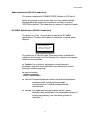
BROTHER FAX-BACK SYSTEM
Brother Customer Service has installed an easy to use fax-back system so you can get instant
answers to common technical questions and product information for all Brother products. This
is available 24 hours a day, 7 days a week. You can use the system to send the information to
any fax machine, not just the one from which you are calling.
Call and follow the voice prompts to receive faxed instructions on how to use the
system and your index of fax-back subjects.
In USA
1-800-521-2846
In Canada
1-800-685-5381
1-514-685-5381
(within Montreal)
DEALERS/SERVICE CENTERS (USA only)
For the name of a Brother authorized dealer or service center, call 1-800-284-4357.
SERVICE CENTERS (Canada only)
For service center addresses in Canada, call 1-800-853-6660.
INTERNET ADDRESS
For technical questions and downloading drivers: http://www.brother.com
III
IV
REGULATIONS
Laser Printer
HL-3260N
USER’S GUIDE
(For USA & CANADA Only)
IMPORTANT NOTE: For technical and operational assistance, you must call the country where you
purchased the printer. Calls must be made from within that country.
In USA
1-800-276-7746
In Canada
1-800-853-6660
1-514-685-6464
(within Montreal)
If you have comments or suggestions, please write us at:
In USA
Printer Customer Support
Brother International Corporation
15 Musick
Irvine, CA 92618
In Canada
Brother International Corporation (Canada), Ltd.
- Marketing Dept.
1, rue Hôtel de Ville
Dollard-des-Ormeaux, PQ, Canada H9B 3H6
BROTHER FAX-BACK SYSTEM
Brother Customer Service has installed an easy to use fax-back system so you can get instant answers to common technical
questions and product information for all Brother products. This is available 24 hours a day, 7 days a week. You can use the
system to send the information to any fax machine, not just the one from which you are calling.
Call and follow the voice prompts to receive faxed instructions on how to use the system and your index of faxback subjects.
In USA
1-800-521-2846
In Canada
1-800-685-5381
1-514-685-5381 (within Montreal)
DEALERS/SERVICE CENTERS (USA only)
For the name of a Brother authorized dealer or service center, call 1-800-284-4357.
SERVICE CENTERS (Canada only)
For service center addresses in Canada, call 1-800-853-6660.
INTERNET ADDRESS
For technical questions and downloading drivers: http://www.brother.com
i
USER’S GUIDE
Definitions of Warnings, Cautions and Notes
The following conventions are used in this User’s Guide:
Warning
•
!
Indicates warnings that must be observed to prevent possible personal
injury.
Caution
•
Indicates cautions that must be observed to use the printer properly or
prevent damage to the printer.
•
Indicates notes and useful tips to remember when using the printer.
✒ Note
ii
REGULATIONS
To Use the Printer Safely
Warning
•
•
•
•
•
•
•
•
Connect the power cord directly into a wall outlet and never use an
extension cord.
Confirm that the wall outlet is near the machine and freely
accessible, so that in event of an emergency, it can be unplugged
easily.
Disconnect the power plug (by pulling the plug, not the cord) if the
power cord or plug becomes frayed or damaged.
To avoid hazardous electric shock or laser radiation exposure, do
not remove any covers or screws other than those specified in this
manual.
Turn off the power and disconnect the power plug (by pulling the
plug, not the cord) if any of the following conditions exist:
You spill something into the equipment.
You suspect that your equipment needs service or repair.
Your equipment’s cover has been damaged.
Do not incinerate spilled toner or used toner. Toner dust is
flammable and might ignite when exposed to an open flame.
Disposal should take place at an authorized dealer or appropriate
collection site.
If you dispose of the used toner containers yourself, dispose of
them according to local regulations.
iii
USER’S GUIDE
!
Caution
•
•
•
•
•
•
•
•
•
Protect the equipment from dampness or wet weather.
Unplug the power cord from the wall outlet before you move
the equipment. While moving the equipment, you should take
care that the power cord will not be damaged under the
equipment.
When you disconnect the power from the wall outlet, always
pull the plug, not the cord.
Do not allow paper clips, staples, or other small metallic
objects to fall inside the equipment.
Do not eat or swallow toner.
Keep toner (used or unused) and toner cartridges out of the
reach of children.
For environmental reasons, dispose of the equipment and
supplies through an authorized dealer or an appropriate
collection site. Contact your local waste disposal facility for
further specific instructions for your area.
Our products are engineered to meet the highest standards of
quality and functionality. When purchasing consumables or
supplies, we recommend those specified by an authorized
dealer.
The inside of the machine becomes very hot. Do not touch the
parts with a label indicating a “hot surface”. Touching a “hot
: means “hot
surface” could result in a burn injury. (
surface”)
iv
REGULATIONS
TABLE OF CONTENTS
TABLE OF CONTENTS
CHAPTER 1 ABOUT THIS PRINTER
What is included in the Carton ............................................ 1-1
Components .................................................................................. 1-1
General view.................................................................................. 1-6
Positioning the Printer ............................................................ 1-9
Power supply ................................................................................. 1-9
Environment ................................................................................ 1-10
What kind of paper can I use ............................................. 1-13
Print media and sizes .................................................................. 1-14
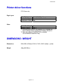
Printing methods ..................................................................... 1-18
Paper handling ........................................................................ 1-19
Loading paper in the standard paper tray .................................... 1-20
Changing the paper size of the Paper tray................................... 1-22
Printing on Labels, Transparencies etc........................................ 1-29
CHAPTER 2 DRIVER AND SOFTWARE
Printer driver ............................................................................... 2-1
Features in the PCL printer driver (only for Windows) ................... 2-2
Features in the PS printer driver (only for Windows)..................... 2-9
Features in the bonus software (only Windows users)................. 2-14
Software for network.................................................................... 2-16
Software for Windows computers ................................................ 2-18
Software for Macintosh computers (only via Network) ................. 2-19
Automatic emulation selection........................................... 2-21
Automatic interface selection ............................................. 2-23
Printer settings......................................................................... 2-24
Factory settings ........................................................................... 2-24
v
USER’S GUIDE
CHAPTER 3 CONTROL PANEL
Control panel .............................................................................. 3-1
SWITCHES ................................................................................. 3-2
GO switch ...................................................................................... 3-3
JOB CANCEL switch ..................................................................... 3-4
SECURE PRINT switch ................................................................. 3-5
REPRINT switch ............................................................................ 3-6
+ , – Switch.................................................................................. 3-14
SET switch................................................................................... 3-15
BACK Switch ............................................................................... 3-16
LEDs............................................................................................ 3-17
LCD MESSAGES ........................................................................ 3-18
Menus ......................................................................................... 3-22
vi
REGULATIONS
CHAPTER 4 OPTIONS
TABLE OF CONTENTS
Optional Accessories .............................................................. 4-1
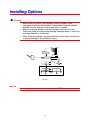
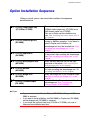
Installing Options ...................................................................... 4-2
Option Installation Sequence ......................................................... 4-3
Lower Tray Unit (LT-5100, LT-5200) ................................ 4-4
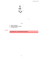
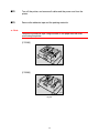
Installing the Lower paper tray....................................................... 4-4
Loading Paper into the Lower tray unit ........................................ 4-12
Setting the Media from the Printer Driver..................................... 4-13
Interchange Unit (SP-5000)................................................ 4-14
Installing the Interchange unit ...................................................... 4-14
Duplex unit (DX-5000) .......................................................... 4-20
Installing the Duplex Unit ............................................................. 4-20
Multi-purpose tray (MP-5000) ............................................ 4-29
Manual Feed................................................................................ 4-29
Installing the Multi-purpose tray ................................................... 4-29
Loading paper on the Multi-purpose tray ..................................... 4-35
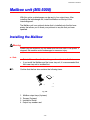
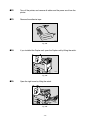
Mailbox unit (MX-5000) ........................................................ 4-39
Installing the Mailbox ................................................................... 4-39
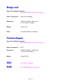
Bridge Unit (BU-5000) .......................................................... 4-44
Installing the Bridge Unit.............................................................. 4-44
Finisher/Stapler (FS-5050) ................................................. 4-50
Installing the Finisher/Stapler....................................................... 4-50
CompactFlash card ................................................................ 4-55
Installing a CompactFlash Card................................................... 4-55
RAM Expansion ...................................................................... 4-57
Minimum Memory Recommendation
(Including 16 Megabytes of internal memory) .............................. 4-57
Installing additional memory ........................................................ 4-59
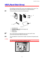
HDD (Hard Disk Drive) ......................................................... 4-62
vii
USER’S GUIDE
CHAPTER 5 MAINTENANCE
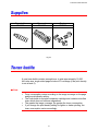
Supplies ....................................................................................... 5-1
Toner bottle................................................................................. 5-1
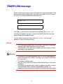
TONER LOW message.................................................................. 5-2
Drum unit ..................................................................................... 5-7
Cleaning ...................................................................................... 5-13
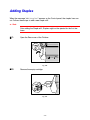
Adding Staples ............................................................................ 5-20
viii
REGULATIONS
CHAPTER 6 TROUBLE SHOOTING
TABLE OF CONTENTS
LCD MESSAGES ..................................................................... 6-1
Error messages ............................................................................. 6-1
Maintenance messages ................................................................. 6-4
Service call messages ................................................................... 6-5
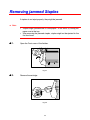
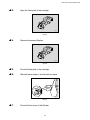
Removing jammed Staples ................................................... 6-6
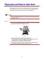
Paper jams and How to clear them ................................... 6-8
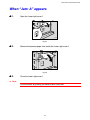
When “Jam: A” appears................................................................. 6-9
When “Jam: B” appears............................................................... 6-10
When “Jam: C” appears............................................................... 6-12
When “Jam: D” appears............................................................... 6-15
When “Jam: E” appears............................................................... 6-17
When “Jam: R” appears............................................................... 6-18
When “Jam: Y” appears............................................................... 6-19
When “Jam: Z” appears ............................................................... 6-20
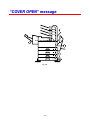
“COVER OPEN” message .................................................. 6-22
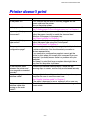
Printer doesn’t print ............................................................... 6-23
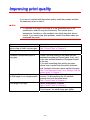
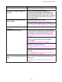
Improving print quality .......................................................... 6-24
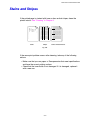
Stains and Stripes ....................................................................... 6-27
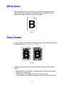
White Spots ................................................................................. 6-28
Toner Scatter............................................................................... 6-28
Black Page .................................................................................. 6-29
White Page .................................................................................. 6-29
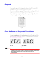
Dropout........................................................................................ 6-30
Poor Halftone or Grayscale Transitions ....................................... 6-30
ix
USER’S GUIDE
APPENDICES
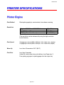
PRINTER SPECIFICATIONS ................................. Appendix-1
Printer Engine................................................................... Appendix-1
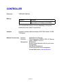
CONTROLLER ................................................................. Appendix-2
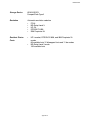
SOFTWARE ..................................................................... Appendix-4
Electrical and Mechanical ................................................. Appendix-5
OTHERS........................................................................... Appendix-5
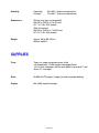
OPTIONS ....................................................................... Appendix-7
500x2 sheets paper tray (LT-5100)................................... Appendix-7
2000 sheets paper tray (LT-5200) .................................... Appendix-7
Multi-purpose tray (MP-5000) ........................................... Appendix-8
Interchange unit................................................................ Appendix-8
Duplex unit........................................................................ Appendix-9
Mailbox ............................................................................. Appendix-9
Bridge unit ...................................................................... Appendix-10
Finisher/Stapler .............................................................. Appendix-10
RAM ............................................................................... Appendix-10
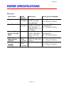
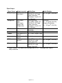
PAPER SPECIFICATIONS ................................... Appendix-11
SYMBOL/CHARACTER SETS ............................ Appendix-14
OCR Symbol Sets........................................................... Appendix-16
HP LaserJet Mode .......................................................... Appendix-17
EPSON Mode ................................................................. Appendix-17
IBM Mode ....................................................................... Appendix-18
HP-GL Mode................................................................... Appendix-18
Symbol Sets Supported by the Printer’s TrueType™, Type 1
Compatible Fonts and Original Typefaces ...................... Appendix-21
Bar Code Control ............................................................ Appendix-23
INDEX
x
REGULATIONS
IMPORTANT INFORMATION:
REGULATIONS
Federal Communications Commission(FCC) Declaration of Conformity
(For USA Only)
Responsible Party :
Brother International Corporation
100 Somerset Corporate Boulevard
Bridgewater, NJ 08807-0911, USA
TEL : (908) 704-1700
declares, that the products
Product Name
: Brother Laser Printer HL-3260N
Model Number
: HL-3260N
Product Options : ALL
complies with Part 15 of the FCC Rules. Operation is subject to the
following two conditions: (1) This device may not cause harmful
interference, and (2) this device must accept any interference received,
including interference that may cause undesired operation.
This equipment has been tested and found to comply with the limits for
a Class B digital device, pursuant to Part 15 of the FCC Rules. These
limits are designed to provide reasonable protection against harmful
interference in a residential installation. This equipment generates,
uses, and can radiate radio frequency energy and, if not installed and
used in accordance with the instructions, may cause harmful
interference to radio communications. However, there is no guarantee
that interference will not occur in a particular installation. If this
equipment does cause harmful interference to radio or television
reception, which can be determined by turning the equipment off and
on, the user is encouraged to try to correct the interference by one or
more of the following measures:
− Reorient or relocate the receiving antenna.
− Increase the separation between the equipment and receiver.
− Connect the equipment into an outlet on a circuit different from that
to which the receiver is connected.
− Consult the dealer or an experienced radio/TV technician for help.
xi
USER’S GUIDE
Important
A shielded interface cable should be used in order to ensure
compliance with the limits for a Class B digital device.
Changes or modifications not expressly approved by Brother
Industries, Ltd. could void the user’s authority to operate the
equipment.
Industry Canada Compliance Statement (For Canada Only)
This Class B digital apparatus complies with Canadian ICES-003.
Cet appareil numérique de la classe B est conforme à la norme NMB003 du Canada.
International ENERGY STAR Compliance Statement
The purpose of the International ENERGY STAR Program is to
promote the development and popularization of energy-efficient office
equipments.
As an ENERGY STAR Partner, Brother Industries, Ltd. has determined
that this product meets the ENERGY STAR guidelines for energy
efficiency.
xii
REGULATIONS
Laser Safety (110-120 V model only)
This printer is certified as a Class I laser product under the U.S.
Department of Health and Human Services (DHHS) Radiation
Performance Standard according to the Radiation Control for Health
and Safety Act of 1968. This means that the printer does not produce
hazardous laser radiation.
Since radiation emitted inside the printer is completely confined within
protective housings and external covers, the laser beam cannot
escape from the machine during any phase of user operation.
FDA Regulations (110-120 V model only)
U.S. Food and Drug Administration (FDA) has implemented regulations
for laser products manufactured on and after August 2, 1976.
Compliance is mandatory for products marketed in the United States.
The label shown on the back of the printer indicates compliance with
the FDA regulations and must be attached to laser products marketed
in the United States.
MANUFACTURED:
BROTHER INDUSTRIES, LTD.
15-1 Naeshiro-cho, Mizuho-ku, Nagoya, 467-8561 Japan
This product complies with FDA radiation performance standards, 21
CFR Subchapter J.
☛ Caution: Use of controls, adjustments or performance of
procedures other than those specified in this manual may
result in hazardous radiation exposure.
xiii
USER’S GUIDE
DECLARATION OF CONFORMITY (EUROPE)
We,
Brother Industries, Ltd.,
15-1, Naeshiro-cho, Mizuho-ku, Nagoya 467-8561, Japan.
declare that this product is in conformity with the following normative
documents:
Safety:
EMC:
:
EN 60950,
EN 60825
EN 55022 Class B, EN 55024
EN61000-3-2, EN61000-3-3
following the provisions of the Low Voltage Directive 73/23/EEC and
the Electromagnetic Compatibility Directive 89/336/EEC (as amended
by 91/263/EEC and 92/31/EEC).
Issued by:
Brother Industries, Ltd.
Information & Document Company
xiv
REGULATIONS
Radio Interference(220-240 V model only)
This printer complies with EN55022(CISPR Publication 22)/Class B.
Before this product is used, ensure that you use a double-shielded
interface cable with twisted-pair conductors and that it is marked
“IEEE1284 compliant”. The cable must not exceed 1.8 metres in length.
IEC 60825 Specification (220-240 V model only)
This printer is a Class 1 laser product as defined in IEC 60825
specifications. The label shown below is attached in countries where
required.
CLASS 1LASER PRODUCT
APPAREIL Å LASER DE CLASSE 1
LASER KLASSE 1 PRODUKT
This printer has a Class 3B Laser Diode which emits invisible laser
radiation in the Scanner Unit. The Scanner Unit should not be opened
under any circumstances.
☛ Caution: Use of controls, adjustments or performance of
procedures other than those specified in this manual may result in
hazardous radiation exposure.
For Finland and Sweden
LUOKAN 1 LASERLAITE
KLASS 1 LASER APPARAT
☛ Varoitus! Laitteen käyttäminen muulla kuin tässä käyttöohjeessa
mainitulla tavalla saattaa altistaa käyttäjän
turvallisuusluokan 1 ylittävälle näkymättömälle
lasersäteilylle.
☛ Varning –Om apparaten används på annat sätt än i denna
Bruksanvisning specificerats, kan användaren utsättas för
osynlig laserstrålning, som överskrider gränsen för
laserklass 1.
xv
USER’S GUIDE
IMPORTANT - For Your Safety
To ensure safe operation the three-pin plug supplied must be inserted
only into a standard three-pin power point which is properly earthed
through the normal household wiring.
Extension cords should not be used with the equipment. If it is
essential that an extension cord has to be used, it must be a three-pin
plug type and correctly wired to provide proper grounding. Incorrectly
wired extension cords may cause personal injury and equipment
damage.
The fact that the equipment operates satisfactorily does not imply that
the power is earthed and that the installation is completely safe. For
your safety, if in any doubt about the effective grounding of the power,
consult a qualified electrician.
Operator Safety
This machine is considered a CDRH class 1 laser device, safe for
office/EDP use. The machine contains 5-milliwat, 700 – 800 nanometer
wavelength, GaAIAs laser diodes. Direct (or indirect reflected) eye
contact with the laser beam might cause serious eye damage. Safety
precautions and interlock mechanisms have been designed to prevent
any possible laser beam exposure to the operator.
Caution
Use of controls or adjustment or performance of procedures other than
those specified in this manual might result in hazardous radiation
exposure.
xvi
REGULATIONS
Disconnect Device
This printer must be installed near a power outlet that is easily
accessible. In case of emergencies, you must disconnect the power
cord from the power outlet to shut off the power completely.
Geräuschemission / Acoustic Noise Emission (For Germany Only)
Lpa < 70dB (A) DIN 45635-19-01-KL2
Wiring Information (For U.K. only)
Important
If the mains plug supplied with this printer is not suitable for your
socket outlet, remove the plug from the mains cord and fit an
appropriate three pin plug. If the replacement plug is intended to take a
fuse then fit the same rating fuse as the original.
If a moulded plug is severed from the mains cord then it should be
destroyed because a plug with cut wires is dangerous if engaged in a
live socket outlet. Do not leave it where a child might find it!
In the event of replacing the plug fuse, fit a fuse approved by ASTA to
BS1362 with the same rating as the original fuse.
Always replace the fuse cover. Never use a plug with the cover omitted.
WARNING - THIS PRINTER MUST BE EARTHED
xvii
USER’S GUIDE
The wires in the mains cord are colored in accordance with the
following code :
GREEN AND YELLOW: EARTH
BLUE
: NEUTRAL
BROWN
: LIVE
The colors of the wires in the mains lead of this printer may not
correspond with the colored markings identifying the terminals in your
plug.
If you need to fit a different plug, proceed as follows.
Remove a length of the cord outer sheath, taking care not to damage
the colored insulation of the wires inside.
xviii
REGULATIONS
Cut each of the three wires to the appropriate length. If the
construction of the plug permits, leave the green and yellow wire
longer than the others so that, in the event that the cord is pulled out of
the plug, the green and yellow wire will be the last to disconnect.
Remove a short section of the colored insulation to expose the wires.
The wire which is colored green and yellow must be connected to the
terminal in the plug which is marked with the letter “E” or by the safety
earth symbol , or colored green or green and yellow.
The wire which is colored blue must be connected to the terminal
which is marked with the letter “N” or colored black or blue.
The wire which is colored brown must be connected to the terminal
which is marked with the letter “L” or colored red or brown.
The outer sheath of the cord must be secured inside the plug. The
colored wires should not hang out of the plug.
xix
CHAPTER 1 ABOUT THIS PRINTER
C H A PTER 1
A B O U T TH I S PR I N TER
1
CHAPTER 1 ABOUT THIS PRINTER
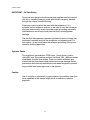
What is included in the Carton
Components
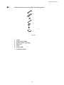
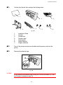
When you unpack the printer, check to see that you have all of the following
parts:
1
3
7
2
5
4
6
1.
2.
3.
4.
5.
6.
7.
Printer
Toner (in the standard tray)
Drum (pre-installed)
CD-ROM*
AC power cord*
Documents*
Tray number seal
*These parts are in the Localization kit in Europe.
Fig. 1-1
✒ Note
You may have additional parts that are not listed above depending on the
country where you purchased the printer.
1-1
✒ Note
Parallel Interface Cable
• An interface cable is not supplied as standard. Please purchase an
appropriate cable according to the interface you intend to use. The power
cord may differ slightly from this figure depending on the country where
you purchased the printer.
• For parallel connections, an IEEE 1284 bi-directional parallel cable is
recommended. Most parallel cables support bi-directional
communication, but some might have an incompatible pin assignment or
may not be IEEE 1284 compliant.
• Do not use a parallel cable that is longer than 3 meters (10 feet).
1-2
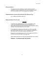
CHAPTER 1 ABOUT THIS PRINTER
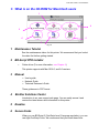
! What is on the CD-ROM
Fig. 1-2
1-3
1
Install software
For all users
•
•
Printer driver (For more information, see Chapter 2)
Automatic e-mail printing (For more information, see Chapter 2)
For administrators
• BRAdmin Professional
• Network Printer Driver Wizard
• Network Print Software
• Storage Manager
• Analysis Tool Software
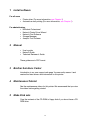
2
Manual
•
•
•
User’s guide
Network Guide
Technical Reviewer’s Guide
These guides are in PDF format.
3
Brother Solutions Center
Introduction to our user support web page. You can easily access it and
receive the latest drivers and information for this printer.
4
Maintenance Tutorial
See the maintenance videos for this printer. We recommend that you view
the videos before getting started.
5
Make Disk sets
Copy the contents of the CD-ROM to floppy disks if you do not have a CDROM drive.
1-4
CHAPTER 1 ABOUT THIS PRINTER
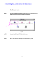
! What is on the CD-ROM for Macintosh users
1
4
2
5
6
3
Fig. 1-3
1
Maintenance Tutorial
See the maintenance videos for this printer. We recommend that you look at
the video first before getting started.
2
BR-Script PPD Installer
•
Printer driver (For more information, see Chapter 2)
This printer supports with Mac OS 8.0, and 9.0 versions.
3
Manual
•
•
•
User’s guide
Network Guide
Technical Reviewer’s Guide
These guides are in PDF format.
4
Brother Solutions Center
Introduction to our user support web page. You can easily access it and
receive the latest drivers and information for this printer.
5
Readme
6
Screen Fonts
When you use BR-Script 3 (PostScript level 3 language emulation), you can
use Agfa PostScript Fonts. We recommend that you install these fonts.
1-5
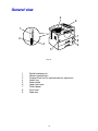
General view
4
6
1
7
8
9
2
3
5
Fig. 1-4
1
2
3
4
5
6
7
8
9
Parallel interface port
Network interface port
CompactFlash slot (for optional memory expansion)
Output tray
Power switch
Upper right cover
Control panel
Front cover
Paper tray
1-6
CHAPTER 1 ABOUT THIS PRINTER
3
4
1
2
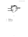
Fig. 1-5
1
2
3
4
Right cover
Lower right cover
Printer board cover
Power cord inlet
1-7
1
2
6
3 4 5
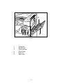
Fig. 1-6
1
2
3
4
5
6
Fusing unit
Transfer unit
Toner lock lever
Toner holder
Drum unit
Right cover
1-8
CHAPTER 1 ABOUT THIS PRINTER
Positioning the Printer
Please take note of the following before using the printer.
!
Caution
•
•
Install this printer on a flat and level surface. The printer base may be
damaged if it is not installed on a level surface.
If you install the optional Lower tray, please be careful not to move the
printer onto an uneven or sloping floor surface. The printer base may be
damaged.
Power supply
Use the printer within the specified power range.
AC power:
Frequency:
±10% of the rated power voltage
50/60 Hz (220-240 V) or 60 Hz (110-120 V)
Do not use an extension power cord. Connect the printer power cord directly
to the power socket.
Do not share the same power circuit with other high-power appliances,
particularly an air conditioner, copier, shredder, etc. If it is unavoidable that
you must use the printer with these appliances, we recommend you use a
voltage transformer or a high-frequency noise filter.
Use a voltage regulator if the power source is not stable.
1-9
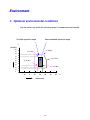
Environment
! Optimum environmental conditions
Use the printer only within the following ranges of temperature and humidity.
Possible operation range
Recommended operation range
%
humidity
100
27°C 80%
15°C 70%
90
80
70
60
50
32°C 54%
15°C 30%
40
30
25°C 30%
20
10
0
- 10
0
10
20
30
temperature
1-10
40
50
°C
CHAPTER 1 ABOUT THIS PRINTER
! Space required for installation
Leave enough space around the printer. This space is necessary to operate
the printer. The recommended (or minimum) space requirements are as
follows:
A
C
B
D
Fig. 1-7
A: more than 10cm (4.0”)
B: more than 45cm (17.8”)
C: more than 75cm (29.6”)
D: more than 10cm (4.0”)
1-11
!
• • • • • • !
•
•
•
•
•
•
•
!
!
!
"
#
$
%
#
!&
!
!
'
&
(
)**+,
-
CHAPTER 1 ABOUT THIS PRINTER
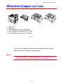
What kind of paper can I use
1
3
4
5
2
1.
2.
3.
4.
5.
Paper tray 1
Paper tray 2
Optional multi-purpose tray (MP-5000)
Optional 500x2 sheets paper tray (LT-5100)
Optional 2000 sheets paper tray (LT-5200)
Fig. 1-8
The printer loads paper from the installed standard paper trays, optional
Multi-purpose tray, or optional Lower paper trays.
✒ Note
•
This section refers to the standard paper tray. For information about the
optional Lower paper trays, see “Lower Tray Unit” in Chapter 4.
1-13
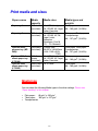
Print media and sizes
Paper source
Media
capacity
Paper tray 1
500 sheets
(cut sheet)
Paper tray 2
Optional multipurpose tray (MP5000)
Optional 500x2
sheets paper tray
(LT-5100)
Optional 2000
sheets paper tray
(LT-5200)
Media sizes
A3, JIS B4, Ledger,
A4, ISO B5, A5, Legal,
Letter, Executive
500 sheets A3, JIS B4, Ledger,
(cut sheet)
A4, ISO B5, A5, A6,
Legal, Letter,
Executive
Envelopes: Com10,
C5, DL, Monarch
100 sheets Custom Size:
(cut sheet)
90-297 x 148-432mm
(3.54-11.69 x 5.8317.01)
500x2
A3, JIS B4, Ledger,
sheets
A4, ISO B5, A5, Legal,
(cut sheet)
Letter, Executive
2000 sheets A4 or Letter
(cut sheet)
Media types and
weights
Plain paper
60 – 105 g/m2 (16-28 lb)
Plain paper, Thick paper,
Transparencies
60 – 157 g/m2 (16-42 lb)
Plain paper, Thick paper,
Transparencies
60 – 157 g/m2 (16-42 lb)
Plain paper
60 – 105 g/m2 (16-28 lb)
Plain paper
60 – 105 g/m2 (16-28 lb)
Media type
You can select the following Media types in the driver settings. Please see,
“Paper handling” in this chapter.
•
•
•
Plain paper : 60 g/m2 to 105 g/m2
Thick paper : 105 g/m2 to 157 g/m2
Transparencies
1-14
CHAPTER 1 ABOUT THIS PRINTER
Recommended paper
Europe
USA
Plain paper
A4: Xerox Premier (80 g/m )
A3, A4, A5: Neusiedler BIO TOP 3
(80g/m²)
Letter: Xerox 4024 (20 lb)
Legal: Xerox 4024 (20 lb)
Transparencies
3M CG3300
Envelopes
Metric
3M CG3300
Crane Crest
2
♦
♦
♦
♦
♦
♦
Before purchasing the large paper quantities, please confirm by
testing small quantities that no problems will occur with the printer.
Use paper made for plain paper copying
2
Use paper which is 75 to 90 g/m
Use neutralized paper, avoid acidic or alkaline paper
Use Long grain paper
Use paper which has a Moisture content of around 5%.
1-15
Plain paper
The printer is designed to work well with most types of xerographic and bond
paper. However, some paper variables may have an effect on print quality or
handling reliability. Always test samples of paper before buying to ensure
that it provides acceptable performance. Some important guidelines when
selecting paper are:
☛ 1.
Your supplier should be informed that the paper or envelopes will be used in
a laser printer.
☛ 2.
Preprinted papers must use inks that can withstand the printer’s fusing
temperature. (392 degrees Fahrenheit or 200 degrees centigrade)
☛ 3.
If selecting a cotton bond paper, paper with a rough surface such as cockle
or laid finished paper, or paper that is wrinkled or puckered, you may
experience less than optimal performance.
✒ Note
The manufacturer does not warrant the use of any particular paper. The
operator is responsible for the quality of paper used with the printer.
1-16
CHAPTER 1 ABOUT THIS PRINTER
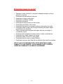
Paper types to avoid
Some types of paper might not perform well or may cause damage to your
printer.
Types of paper to avoid are:
1.
2.
3.
4.
5.
6.
7.
8.
Highly textured paper.
Smooth or shiny paper.
Paper that is coated or has a chemical finish.
Damaged, wrinkled or prefolded paper.
Paper exceeding the recommended weight specified in this manual.
Paper with tabs and staples.
Letterheads using low temperature dyes or thermography.
Multipart or carbonless paper.
DAMAGE OR OTHER DEFECTS CAUSED BY THE USE OF PAPER
LISTED UNDER “PAPER TYPES TO AVOID” WILL NOT BE COVERED
UNDER ANY WARRANTY OR SERVICE AGREEMENTS.
For more information about Special paper, see “Printing on Labels,
Transparencies etc” in this chapter.
1-17
Printing methods
This printer has various printing methods.
Choose the best printing method that you require for your print job.
♦ To print from the standard paper tray 1 or 2.
See “Loading Paper in the Standard paper tray” in this chapter.
♦ To print from the optional Multi-purpose tray
See “Multi-purpose tray” in chapter 4.
♦ To print from the optional Lower tray
See “Lower Tray Unit” in chapter 4.
1-18
CHAPTER 1 ABOUT THIS PRINTER
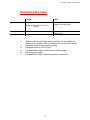
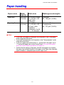
Paper handling
Paper source
Media
capacity
Media sizes
Media types and weights
Paper tray 1
500 sheets
(cut sheet)
Plain paper
60 – 105 g/m2 (16-28 lb)
Paper tray 2
500 sheets
(cut sheet)
A3, ☞JIS B4, Ledger,
A4, ☞ISO B5, ☞A5,
Legal, Letter,
☞Executive
A3, ☞JIS B4, Ledger,
A4, ☞ISO B5, ☞A5,
A6, Legal, Letter,
☞Executive
☞Envelopes: Com10,
C5, DL, Monarch
Plain paper, Thick paper,
Transparencies
60 – 157 g/m2 (16-42 lb)
✒ Note
•
•
•
•
If you load Thick paper or Envelopes, set the printer to the “Thick paper”
mode using the printer driver.
If you load Transparencies, set the printer to the “Transparencies” mode
using the printer driver.
If you set a paper size marked with a ☞, set the dial in the paper tray to
“✳” and set the paper size on the Control Panel. (For more information
about the Control Panel, see Menus in Chapter 3).
Confirm that the setting of the paper size dial in the paper tray matches
the paper size and feed direction of the paper in the Paper tray, otherwise
paper misfeeds or unexpected print results might occur.
1-19
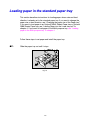
Loading paper in the standard paper tray
This section describes instructions for loading paper whose size and feed
direction is already set in the standard paper tray. If you want to change the
paper size or feed direction, see “Changing the paper size of the Paper tray”.
If you want to load paper in an Optional 500x2 Sheets Paper tray or Optional
2000 Sheets Paper tray, see “Loading Paper into the Lower tray unit” in
chapter 4. If you want to load paper in the Multi-purpose tray, see “Loading
paper in the Multi-purpose tray” in chapter 4.
Follow these steps to set paper and install the paper tray:
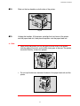
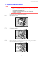
☛ 1.
Slide the paper tray out until it stops.
ZAEY012E
Fig. 1-9
1-20
CHAPTER 1 ABOUT THIS PRINTER
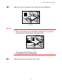
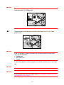
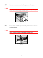
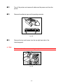
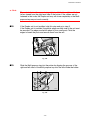
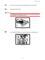
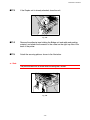
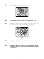
☛ 2.
Align all four sides of the paper stack, and load it into the Paper tray.
ZAEY030E
Fig. 1-10
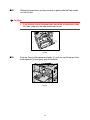
✒ Note
•
•
Do not stack paper over the limit mark.
When you set custom size or thick paper in Paper tray 2, do not stack
paper above the lower limit mark (①) in Paper tray 2.
ZAEY052E
Fig. 1-11
•
•
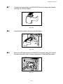
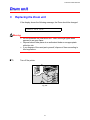
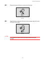
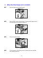
☛ 3.
Set the paper after shuffling the sheets.
Load paper face up into the Paper tray.
Slide the Paper tray into the printer until it stops.
1-21
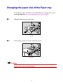
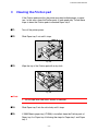
Changing the paper size of the Paper tray
For more information about the size and feed direction of paper that can be
set in the Paper tray, see “Print media and sizes” in this chapter.
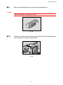
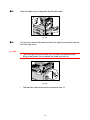
☛ 1.
Slide the Paper tray out until it stops.
ZAEY012E
Fig. 1-12
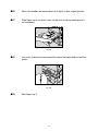
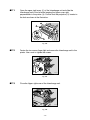
☛ 2.
Set the Paper guide lock to the “unlocked” position.
ZAEY013E
Fig. 1-13
!
Caution
Confirm that the lever of the paper guide lock is released before sliding the
guides, otherwise it can be damaged.
1-22
CHAPTER 1 ABOUT THIS PRINTER
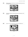
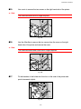
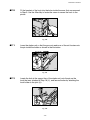
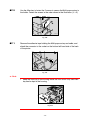
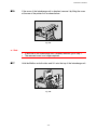
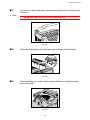
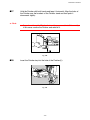
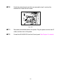
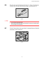
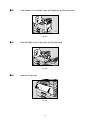
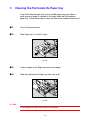
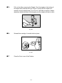
☛ 3.
Slide the side paper guide wide open (②) while pressing the release lever of
the side guide (①).
1
2
ZAEY021E
Fig. 1-14
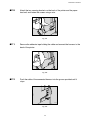
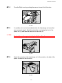
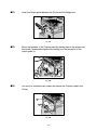
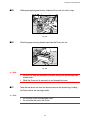
☛ 4.
Slide the rear guide fully to the left while pressing the release lever of the
rear guide.
ZAEY034E
Fig. 1-15
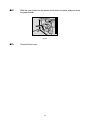
☛ 5.
Align all four sides of the paper stack, and load it into the Paper tray.
ZAEY030E
Fig. 1-16
1-23
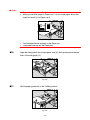
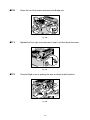
✒ Note
•
•
Do not stack paper over the limit mark.
When you set thick paper in Paper tray 2, do not stack paper above the
lower limit mark (①) in Paper tray 2.
ZAEY052E
Fig. 1-17
•
•
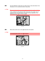
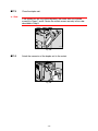
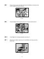
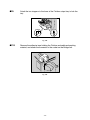
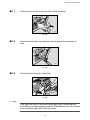
☛ 6.
Fan the paper before setting it in the Paper tray.
Load paper face up into the Paper tray.
Align the side guide to the loaded paper size (②) while pressing the release
lever of the side guide (①).
1
2
ZAEY031E
Fig. 1-18
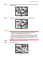
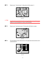
☛ 7.
Set the paper guide lock to the “locked position”.
ZAEY032E
Fig. 1-19
1-24
CHAPTER 1 ABOUT THIS PRINTER
☛ 8.
Align the rear guide to the loaded paper size while pressing the release lever
of the rear guide.
ZAEY033E
Fig. 1-20
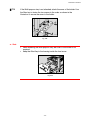
☛ 9.
Adjust the paper size dial in the paper tray for the loaded paper size.
ZAEY050E
Fig. 1-21
✒ Note
•
•
Confirm that the setting of the paper size dial matches the paper size
and feed direction of the paper in the Paper tray, otherwise paper
misfeeds or unexpected printing results might occur.
Confirm that the paper size dial matches the actual paper size loaded in
the Paper tray. If the actual paper size is not shown on the dial, set the
dial to “✱” and specify the paper size using the Control panel. For more
information on specifying the paper size, see “Paper handling” in this
chapter.
☛ 10.
Slide the Paper tray into the printer until it stops.
☛ 11.
Set the paper sensor.
ZAEY260E
Fig.1-22
1-25
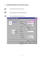
♦ Setting the Media from the Printer driver
☛ 1.
Open the File menu and choose print.
☛ 2.
Open Properties and choose the Paper tab.
☛ 3.
Choose the paper size you want to use.
3
Fig. 1-23
1-26
CHAPTER 1 ABOUT THIS PRINTER
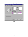
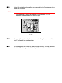
☛ 4.
Choose the Paper tray which you want to print from.
4
Fig. 1-24
1-27
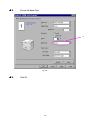
☛ 5.
Choose the Media Type.
5
Fig. 1-25
☛ 6.
Click OK.
1-28
CHAPTER 1 ABOUT THIS PRINTER
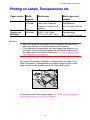
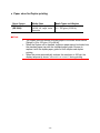
Printing on Labels, Transparencies etc.
Paper source
Media
capacity
Media sizes
Media types and
weights
Paper tray 2
500 sheets
(cut sheet)
Plain paper, Thick paper,
Transparencies
60 – 157 g/m2 (16-42 lb)
Optional Multipurpose tray
(MP-5000)
100 sheets
(cut sheet)
A3, A4, JIS B5, ISO B5, A5,
Legal, Letter, Executive
Envelopes: Com10, C5, DL,
Monarch
Custom Size:
90-297 x 148-432mm
(3.54-11.69 x 5.83-17.01)
Plain paper, Thick paper,
Transparencies
60 – 157 g/m2 (16-42 lb)
✒ Notes
•
•
Be sure to select the same paper size as the paper to be used in your
application software, or correct printing cannot be obtained.
If your application software does not support paper size selection in its
print menu, you can change the paper size with the MP Size setting in
the Paper menu on the Control panel switch. For more information, see
“Multi-purpose tray” in chapter 4.
You can load Thick paper, Envelopes or Transparencies into Paper tray 2.
When Thick paper or Transparencies are loaded, change the lever on the
paper size dial inside the paper tray to the “Thick paper” setting.
ZAEY050E
Fig. 1-26
For more information about special paper, see “Labels and Transparencies”
and “Envelope types to avoid” in this chapter.
1-29
✒ Note
When you set thick paper in Paper tray 2, do not stack paper above the
lower limit mark (①) of Paper tray.
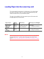
ZAEY052E
Fig. 1-27
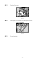
☛ 1.
Change the lever on the paper size dial of the Paper tray 2 to the “Thick
paper” mode.
ZAEY050E
Fig. 1-28
✒ Note
If the “Thick paper” mode is selected, the following functions using Paper
tray 2 are not available.
• Duplex print
• Sort, Shift sort
• Staple
A yellow line appears under the paper size indicator on the front of the Paper
tray.
✒ Note
Reset the lever to the left side after you have finished printing on thick paper.
✒ Note
For making settings from the printer driver, see “Settings the Media from the
Printer driver” in this chapter.
1-30
CHAPTER 1 ABOUT THIS PRINTER
Labels and Transparencies
The printer will print on most type of labels and transparencies designed for
use with a laser printer. Labels should have an adhesive that is acrylicbased since such material is more stable at the high temperatures in the
fusing unit. Adhesives should not come in contact with any part of the
printer, because the label stock may stick to the drum or rollers and cause
jams and print quality problems. No adhesive should be exposed between
the labels. Labels should be arranged so that they cover the entire page with
the only exposed spaces being lengthwise down the sheet. Using labels with
spaces may result in labels peeling off and causing serious jam or print
problems.
All labels and transparencies used in this printer must be able to withstand a
temperature of 200 degrees centigrade (392 degrees Fahrenheit) for a
period of 0.1 seconds.
Label and transparency sheets should not exceed the paper weight
specifications described in the User’s Guide. Labels and transparencies
exceeding this specification may not feed or print properly and cause
damage to your printer.
Print quality, reliability and performance of labels and transparencies cannot
be guaranteed.
DAMAGE CAUSED BY THE USE OF UNSATISFACTORY LABELS OR
TRANSPARENCIES IS NOT COVERED UNDER ANY WARRANTY OR
SERVICE AGREEMENTS.
1-31
•
•
•
•
•
•
•
•
•
•
•
•
•
•
•
CHAPTER 1 ABOUT THIS PRINTER
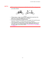
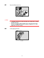
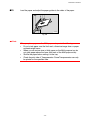
✒ Note
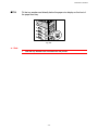
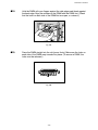
•
Before printing envelopes, you must fan the stack well to avoid paper
jams and misfeeds.
Fig. 1-29
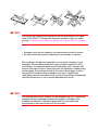
•
•
•
•
Different types of paper should not be loaded at the same time in the
paper tray, it may cause paper jams or misfeeds.
Do not print envelopes by Duplex printing.
Be sure to select the same paper size as the paper to be used from your
application software, or correct printing cannot be obtained.
If your application software does not support paper size selection on its
print menu, you can change the paper size with the MP Size setting in
the Paper Menu on the Control Panel. For more information, see Menus
in Chapter 3.
1-33
✒ Note
If envelopes get smudged during printing, set the print density to a higher
value in the QUALITY settings with the panel operation switch for darker
printouts. To adjust the print density setting, see “Control Panel” in Chapter
3.
• Envelope joints that are sealed by the manufacturer should be secure.
• All sides should be properly folded without any wrinkles or creases.
Most envelopes will perform acceptably on your printer. However, some
envelopes will have feeding and print quality problems because of their
construction. A suitable envelope should have edges with a straight, well
creased folds and should not have more than two thickness of paper along
the lead edge. The envelope should lie flat and not have baggy or flimsy
construction. Purchase quality envelopes only from a supplier who
understands that the envelopes will be used in a laser printer. All envelopes
should be tested prior to use to ensure desirable print results.
✒ Note
The manufacturer neither warrants nor recommends the use of a particular
envelope because envelope properties are subject to change by the
envelope manufacturer. The entire responsibility for the quality and
performance of the envelope lies with the customer.
1-34
CHAPTER 2 BEFORE WORKING WITH THE PRINTER
C H A PTER 2
DRIVER AND SOFTWARE
2
CHAPTER 2 BEFORE WORKING WITH THE PRINTER
Printer driver
The Printer driver is Software that translates data in the format used by a
computer into the format required by a particular printer, typically a printer
command language or page description language.
The following printer drivers for each Operating System are supplied on the
CD-ROM provided with the printer. The latest printer driver can also be
downloaded from Brother Solutions Center http://solutions.brother.com.
For Windows 95/98/Me, Windows NT 4.0 and Windows 2000.
•
PCL (Hewlett-Packard laser printer-LaserJet 5) driver
•
BR-Script (PostScript Level3 language emulation) driver
For Macintosh
•
BR-Script (PostScript Level3 language emulation) driver (For more
information, refer to the Network user’s Guide on the CD-ROM.)
PCL driver
PS driver
Windows 95/98/Me
✔
✔
Windows 2000
✔
✔
Windows NT4.0
✔
✔
✔
Macintosh (via Network)
2-1
Features in the PCL printer driver (only for
Windows)
For more detailed information, please see the on-line help in the printer
driver.
You can also change settings by clicking on the illustration on the left side of
the tab.
1
! Basic tab
2
Fig. 2-1
1
Select the Paper size, Multi-page, Orientation etc.
2
Select the Paper source etc.
2-2
CHAPTER 2 BEFORE WORKING WITH THE PRINTER
! Advanced tab
2
4
3
5
6
1
Fig. 2-2
Tab selection
Change the tab setting by clicking on the icons as follows:
1
2
3
4
5
6
Print Quality
Duplex
Watermark
Page Setting
Device options
Destination
2-3
♦ Print Quality settings
Select the Resolution, Toner save mode and Print settings.
•
You can change the resolution as follows:
300 dpi
600 dpi
•
Toner Save mode
You can save running costs by turning on the Toner Save mode, which
reduces the print density on the page.
•
With Print setting selected to manual, you can change the Brightness,
Contrast, Graphics mode settings and True Type mode options manually.
♦ Duplex function
To use duplex printing, you need to install the optional Duplex unit and
Interchange unit onto your printer. If you select the duplex button, the
dialogue box for making duplex settings appears. 6 types of duplex binding
direction are available for each orientation.
♦ Watermark
You can put a watermarked logo or text into your documents.
When you use a bitmap file as a watermark, you can change the size of the
watermark and place it anywhere you like on the page.
When you use a text as a watermark, you can change the font, darkness
and angle settings.
♦ Page Setting
Change the print image scaling and select Mirror / Reverse printing options.
2-4
CHAPTER 2 BEFORE WORKING WITH THE PRINTER
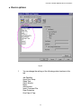
♦ Device options
Fig. 2-3
1
You can change the settings of the following printer functions in this
tab
Job Spooling
Quick Print Setup
Sleep Time
Status Monitor
Macro
Administrator
Insert Command File
Page Protection
Print Date & Time
2-5
Job spooling
You can reprint a document without sending the data from your PC again as
the printer saves data that you identify as being required for reprinting.
•
•
•
•
Last job reprint :
Secure Print :
Public :
Proof :
Reprint the last job
Save the data with a password
Save the data without a password
Save the data and print it
Fig. 2-4
For more information about reprint function, see “REPRINT switch” in
Chapter 3.
2-6
CHAPTER 2 BEFORE WORKING WITH THE PRINTER
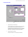
! Accessories tab
1
2
Fig. 2-5
1
Automatic Detection of Printer Options
This function detects the current optional unit devices automatically
and the available functions are reflected in the printer driver.
Recognize the Option automatically by pressing “Auto”, options that
are installed onto the printer will be listed. You can manually add or
delete options. Tray settings etc. will match the fitted options.
2
Advanced Paper Source Setting
Recognizes the paper size in each paper tray automatically.
2-7
! Support tab
•
•
•
•
You can download the latest driver by accessing the Brother Solutions
Center site.
You can see the printer driver version.
You can check the current driver settings.
You can print the Configuration page, Test page, etc.
Fig. 2-6
2-8
CHAPTER 2 BEFORE WORKING WITH THE PRINTER
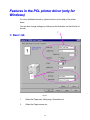
Features in the Post script compatible printer
driver (only for Windows)
For more information, please see the on-line help in the printer driver.
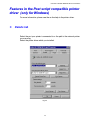
!
Details tab
Select the port your printer is connected to or the path to the network printer
you are using.
Select the printer driver which you installed.
Fig. 2-7
2-9
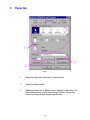
!
Paper tab
1
2
3
Fig. 2-8
1
Select the Paper size, Multi-page, Orientation etc.
2
Select the Paper source.
3
When the Duplex unit or Mailbox unit is installed in the printer, add
the installed options in the Device Options Tab first. The set the
function for those devices by pressing this icon.
2-10
CHAPTER 2 BEFORE WORKING WITH THE PRINTER
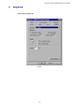
!
Graphics
Set the print quality etc.
Fig. 2-9
2-11
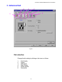
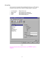
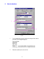
!
Device Options
1
2
Fig. 2-10
1
You can change the settings by clicking the setting and then select a
new value in the Change Settings box.
Toner save Mode
Sleep Mode
Media Type
HRC setting
Collate
(only install the HDD or CompactFlash card)
Job spooling (only install the HDD or CompactFlash card)
2
Select the installed options from the lists.
2-12
CHAPTER 2 BEFORE WORKING WITH THE PRINTER
♦ Job Spooling
You can print a document without resending the data or sending the
password from your PC because the printer saves data that you specify
reprinting.
For more information, see “REPRINT Switch” in Chapter 3.
•
•
•
Secure Print :
Public :
Proof :
Print the data with a password
Save the data without a password
Save the data and print it
2-13
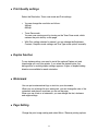
Features in the bonus software (only
Windows users)
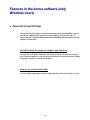
♦ Automatic E-mail Printing
Automatic E-mail printing is used to download e-mail automatically, receive
mail at the selected time and print it automatically. You can also set it to
select the mail to be printed automatically depending on the sender and the
subject of the e-mail.
Search E-mail by the sender and subject, and auto print
As soon as an E-mail is received, the printer prints it without your having to
start the print operation. You can choose the mail you want to print by having
the printer search by sender and subject.
Auto access at the selected time
You can check incoming e-mail by accessing the server at the time you set.
2-14
CHAPTER 2 BEFORE WORKING WITH THE PRINTER
Several mail users can share a PC
Usually, it is difficult to share E-mail software on one PC with several people.
But Automatic E-mail Printing supports multi-users, so several people can
use their E-mail software on one PC.
You can keep the current E-mail software.
Even if you use Netscape or Microsoft Internet Mail, you can use Automatic
E-mail Printing and get additional functions not supplied in the original e-mail
software.
2-15
Software for network
♦ BR-Admin Professional
BRAdmin professional is a utility for managing your Brother network enabled
printers, which runs on Windows 95/98/Me, Windows 2000 and Windows NT
4.0 and allows you to easily configure and check the status of your network
enabled printer.
♦ Storage Manager
Brother Storage Manager software can manipulate the printer forms that you
may have stored in the CompactFlash or 2.5” HDD.
You can print the fixed form document at any time by operating the Control
panel.
To make the fixed document, you must write Fonts, Macros, or fixed forms to
the Storage Device in your printer.
♦ Analysis Tool Software
By adding an HDD to the HL 3260 printer, you can gain a cost analysis
capability.
®
Analysis Tool Software is a 32-bit Windows application designed to manage
important information about the print job, such as the username, job name,
number of printed pages, etc. Using this software you can easily associate
printing costs with users or groups of users.
2-16
CHAPTER 2 BEFORE WORKING WITH THE PRINTER
♦ Network Printer Driver Wizard
Save time and effort by using the Brother Network Printer Driver Wizard
software to automate the installation and configuration of Brother networked
printers in a TCP/IP environment.
Use the Wizard to configure the printer TCP/IP settings and specify the
Printer driver to be used. The Wizard can then create an Executable file
which can be e-mailed to other network users. When run, the Executable file
installs the appropriate printer driver and network printing software directly
on the remote PC.
To access the Network Printer Driver Wizard, insert the CD-ROM supplied
with the printer, click the Install Software icon and select the Network Printer
Driver Wizard.
2-17
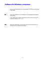
Software for Windows computers
You can install the Software from the supplied CD-ROM by following these
simple steps:
☛ 1.
Insert the CD-ROM into the CD-ROM drive. The opening screen appears
automatically.
If the screen does not appear, click Start and choose Run, enter the CD
drive letter and type START.EXE.
☛ 2.
Select the LANGUAGE, and then follow the on-screen instructions, the
printer driver will complete the installation.
2-18
CHAPTER 2 BEFORE WORKING WITH THE PRINTER
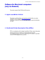
Software for Macintosh computers
(only via Network)
This printer supports Mac OS 8.0 and 9.0 versions.
! Apple LaserWriter 8 Driver
The Apple LaserWriter Driver may have been installed with your system
software. It is also available at http://www.apple.com.
LaserWriter 8 version 8.6 and 8.7 have been tested for use with the Brother
HL-3260.
! PostScript Printer Description Files (PPDs)
PPDs, in combination with the Apple LaserWriter 8 Driver, access the printer
features and allow the computer to communicate with the printer.
An installation program for the PPDs (“BR-Script PPD Installer”) is provided
on the CD-ROM supplied with your printer.
2-19
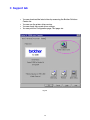
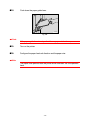
! Installing the printer driver for Macintosh
<For Network user>
☛ 1.
Turn on your Macintosh computer. Insert the CD-ROM into the CD-ROM
drive. The following Window will appear automatically.
2
Fig. 2-11
☛ 2.
To install the BR-Script PPD file, click this icon.
☛ 3.
Set up the LaserWriter referring to the Network user’s guide.
2-20
CHAPTER 2 BEFORE WORKING WITH THE PRINTER
Automatic emulation selection
This printer has an Automatic emulation selection function. When the printer
receives data from the computer, it automatically selects the emulation
mode. This function has been factory set to ON.
The printer can select the emulation among the following combinations:
EPSON (default)
HP LaserJet
BR-Script 3
HP-GL
EPSON FX-850
IBM
HP LaserJet
BR-Script 3
HP-GL
IBM Proprinter XL
You can also select the emulation mode manually with the EMULATION
menu in PRINT MENU mode by using the Control panel. For more
information, see Chapter 3.
2-21
✒ Note
When you use the Automatic emulation selection, note the following:
•
The EPSON or IBM emulation mode priority must be selected, as the
printer cannot distinguish between them. Since the factory setting is the
EPSON emulation mode, you might need to select the IBM emulation
mode with EMULATION menu in SETUP mode by using the Control
panel when you need to use this emulation.
•
Try this function with your application software or network server. If the
function does not work properly, select the required emulation mode
manually using the printer panel switches or use emulation selection
commands from your software.
2-22
CHAPTER 2 BEFORE WORKING WITH THE PRINTER
Automatic interface selection
This printer has an Automatic interface selection function. When the printer
receives data from the computer, it automatically selects the interface as
appropriate.
When you use the parallel interface, you can turn the high-speed and bidirectional parallel communications on or off with parallel menu in
INTERFACE mode by using the Control panel. For further information, see
Chapter 3. Since the automatic interface selection mode has been factory
set to ON, simply connect the interface cable to the printer.
If a Network board (Brother NC-4100h) has been installed, Select
NETWORK mode by using the Control panel
When necessary, select the interface or the network communications
parameters manually with the INTERFACE mode by using the Control panel.
For further information, see Chapter 3. For the settings on the computer, see
the manual of the computer or software you are using.
✒ Note
When you use the Automatic interface selection, note the following:
•
This function takes a few seconds to work. If you want to speed up
printing, select the required interface manually with the SELECT menu
in INTERFACE mode by using the Control panel.
If you constantly use only one interface, we recommend that you select that
interface in the INTERFACE mode. The printer allocates all of the input buffer
to that interface if only one interface is selected.
2-23
Printer settings
Factory settings
The printer settings have been set at the factory before shipment. They are
called “Factory settings.” Although you can operate the printer with these
factory settings unchanged, you can tailor the printer by making user
settings. Please see “List of Factory settings” in Chapter 3.
✒ Note
Changing the user settings does not affect factory settings. You cannot
modify the preset factory settings.
The changed user settings can be restored to the factory default settings
with the RESET MENU mode. For further information, see Chapter 3.
2-24
CHAPTER 3 CONTROL PANEL
C H A PTER 3
CONTROL PANEL
3
CHAPTER 3 CONTROL PANEL
Control panel
Fig. 3-1
3-1
USER’S GUIDE
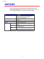
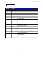
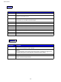
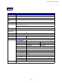
SWITCHES
You can control the basic printer operations and change various printer
settings with 8 switches (Go, Job Cancel, Secure Print, Reprint, +, −, Set,
Back). Functions available are shown above the panel switches.
K
Keeyy
Go
Job Cancel
Secure Print
Reprint
Menu
+
Set
Back
FFuunnccttiioonn
Exit from the Control panel menu, Reprint
settings and Clear error messages.
Pause / Continue printing.
Stop and cancel the printer operation in
progress.
Print secure documents.
Select the Reprint menu.
Move forwards and backwards through
Menus.
Move forwards and backwards through
selectable options.
Select the Control panel menu.
Set the selected menu and setting values.
Go back one level in the menu structure.
3-2
CHAPTER 3 CONTROL PANEL
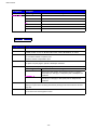
GO switch
You can change from the current status (MENU, ERROR and REPRINT
settings) by pressing the Go switch once. For ERROR indications, the panel
will change only when it is possible to clear the error.
You can PAUSE printing with the Go switch during a print job. Pressing the
Go switch again makes the print job restart and clears the PAUSE. During
PAUSE, the printer is in the off-line state.
✒ Note
If you do not wish to print the remaining data when the printer is in PAUSE,
you can cancel the job by pressing the Job Cancel switch before pressing
the Go switch to clear the PAUSE.
3-3
USER’S GUIDE
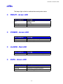
NO DATA!!!
JOB CANCELLING
READY
3-4
CHAPTER 3 CONTROL PANEL
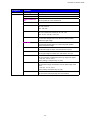
SECURE PRINT switch
This function makes it possible to submit a print job to the printer and have
that job print only when you interact with the printer via the front panel, or via
a web browser. This functionality allows you to print secure data to be
printed only while you are at the printer.
You can use the secure print function when the printer is READY or in the
menu settings.
☛ 1.
Press the Secure Print switch.
☛ 2.
Select the user name, the job, password and the print copy quantity.
☛ 3.
Press the Set or the Secure Print switch to start printing.
✒ Notes
•
•
The secure print function does not support off-line or paused printing.
When there is no secure data and you press the Secure Print switch,
the LCD shows “NO DATA STORED” for a short time.
When you want to use the secure print function, refer to “Operations for
printing SECURE data” in this chapter.
3-5
USER’S GUIDE
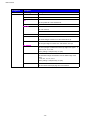
REPRINT switch
If you want to reprint a document that has just been printed, you can reprint
it by pressing the Reprint switch. Also, if you have created a document that
you wish to share with colleagues, simply spool the document to a nonsecure area of the printer. This document can then be re-printed by anyone
who is on the network or at the printer Control panel.
You can use the reprint function when the printer is READY or in the settings
menu.
When you want to print PROOF, PUBLIC or SECURE data, we recommend
installing the optional HDD or Compact Flash.
If you do not install an HDD (See HDD in Chapter 4) or Compact Flash Card
(see Compact Flash Card in Chapter 4), you can reprint from RAM.
When you use RAM to reprint;
☛ 1.
Press the Set switch on the Control panel to exit from the READY status and
select RAMDISK SIZE in the SETUP mode.
☛ 2.
The default RAM is 0MB. Press the + switch to increase the reprint RAM
size in 1MB steps.
✒ Notes
•
•
When you increase the RAM size to use for secure printing, the work
area of the printer is decreased and the printer performance will reduce.
Ensure that you reset the RAMDISK SIZE to 0MB when you have
finished using secure printing.
When you store the data in RAM, the data is deleted when the printer
power is turned off.
We also recommend adding additional RAM when you want to secure print a
large amount of data. (See RAM expansion in Chapter 4)
3-6
CHAPTER 3 CONTROL PANEL
!
Reprinting the Last JOB
You can reprint the last print job data without sending it from the computer
again.
✒ Notes
•
•
•
•
When REPRINT is selected off on the panel and you press the Reprint
switch, the LCD shows “NO DATA STORED” for a short time.
If you want to cancel reprinting, press the Job Cancel switch.
If the printer does not have enough memory to spool the print job data, it
prints the last page only.
Pressing the – or + switch makes the number or reprint copies decrease
or increase. You can select between COPIES= 1 and COPIES=999.
3-7
USER’S GUIDE
[Reprint the last JOB 3 times]
☛ 1.
Set the reprint function ON in the Control panel settings.
✒ Notes
If you print using this printer’s own driver, the settings for Job Spooling in the
printer driver will take priority over the settings made in the Control Panel.
For more information, see “Job Spooling” in Chapter 2.
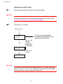
☛ 2.
Press the Reprint switch.
Press Reprint.
If you do not make a selection
immediately, the display clears the
reprint menu automatically.
--REPRINT-COPIES=
1
Press + until
the next
screen as
shown below
is displayed.
--REPRINT-COPIES=
3
Press Set or
Reprint.
PRINTING
✒ Notes
If you want to reprint the data and have pressed the Go switch, the display
shows “PRESS SET TO PRINT”. Press the Set switch to start the reprint
job or press the Go switch to cancel the reprint job.
3-8
CHAPTER 3 CONTROL PANEL
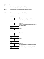
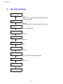
!
Printing PROOF data
You can use this function to reprint PROOF data that has just been printed
and has no security settings. Documents that are placed in the PROOF area
are available to anyone. This function can also be used if it is a document
that will be moved over to the public folder at a later date.
When the area to spool data is full, the earliest data is automatically deleted
first. The order of deleting data is not connected to the order of reprinting.
When you reprint PROOF data, refer also to “Operations for reprinting
SECURE data” in this chapter.
✒ Notes
•
•
•
If you have not installed the optional HDD or Compact Flash, the reprint
data is deleted when off the printer is turned off.
If there is data in the job information which cannot be displayed on the
LCD, the display shows “?”.
You can also reprint the job by using the supplied printer driver.
3-9
USER’S GUIDE
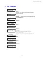
!
Printing PUBLIC data
You can use this function to reprint documents stored in a PUBLIC area of
the printer memory. Any documents here will not be password protected and
anyone can access them using the Control panel or a web browser. The
printer will not print a PUBLIC document when you send it to the printer. You
must use the Control panel of the printer or connect to the printer through a
web browser.
Public data can be deleted through the Control panel of the printer or from
the web based management software.
When you reprint PUBLIC data, refer also to “Operations for reprinting
SECURE data” in this chapter.
✒ Notes
•
•
If there is data in the job information that cannot be displayed on the
LCD, the display shows “?”.
You can also reprint the job by using the supplied printer driver.
3-10
CHAPTER 3 CONTROL PANEL
!
Printing SECURE data
Secure documents are password protected and only those people that know
the password will be able to print the document. The printer will not print the
document when you send it for printing, to print the document you must use
the control panel of the printer or connect to the printer using a web browser.
When you want to delete the spooled data, you can carry out this operation
on the control panel or in the web based management software.
✒ Notes
•
•
If there is data in the job information which cannot be displayed on the
LCD, the display shows “?”.
You can also reprint the job by using the supplied printer driver.
For more information about the settings in the printer driver, see “Job
Spooling” in Chapter 2.
3-11
USER’S GUIDE
Operations for reprinting SECURE data
NO DATA STORED
Press Reprint
switch.
There is no data.
--REPRINT-LAST JOB
Press the + or – switch.
--REPRINT-SECURE
Press the Set switch.
SECURE
USER
✶✶✶✶✶✶✶
USER
JOB
✶✶✶✶✶✶✶
✶✶✶✶✶✶✶
JOB
✶✶✶✶✶✶✶
PASS NO.= 0000
--REPRINT-COPIES=
1
Press the + or – switch to select the user name.
Press the Set switch to set the user name.
Press the + or – switch to select the job.
Press the Set switch to set the job.
Input your password.
Press the Set switch to set the password.
The printer will return from
this menu after a timeout.
Press the Set or Reprint switch.
If you press the Go switch, the display shows
“PRESS SET TO PRINT”.
PRINTING
3-12
CHAPTER 3 CONTROL PANEL
♦ When there is no reprint data in memory
If the printer does not have reprint data in buffer memory and you press the
Reprint switch, the LCD shows “NO DATA STORED” for a short time.
♦ To delete the job
Select the ‘DELETE STORAGE’ menu under the SETUP menu of the
Control panel. Select the user name and the job to delete (you need to input
the password to delete secure data).
♦ To cancel the reprint job
Press the Job Cancel to cancel the current reprinting job. The Job Cancel
switch also allows you to cancel a reprint job which is paused by the Go
switch.
3-13
USER’S GUIDE
+ , – Switch
When you press the + or – switch when the printer is the on-line state it goes
off-line and the LCD goes to the menu.
!
To display menus in the current mode
When you press the + or – switch when the printer is the on-line state, it
goes off-line and the LCD displays the current mode.
You can enter other menus in the current mode by pressing the + or –
switch. Pressing the + or – switch scrolls the menus and settings forward or
backward respectively on the display. Press or keep pressing the switch until
you access the desired item.
!
To set numbers
When you want to set numbers, there are two ways to input numbers, either
by scrolling up or down through the available setting range or by selecting
the digit to change and the setting just that digit. When you keep the + or –
switch pressed, the display scrolls up or down faster.
3-14
CHAPTER 3 CONTROL PANEL
SET switch
When you press the Set switch when the printer is the on-line state, it turns
off-line and the LCD goes to the menu display.
Pressing the Set switch allows you to set the selected menu or the default
number. After changing the menu or the number, the asterisk mark appears
on the right side for a short time.
3-15
USER’S GUIDE
BACK Switch
When you press the Back switch when the printer is the on-line state, it
turns off-line and the LCD goes to the menu display.
Pressing the Back switch allows you to return to the previous level from the
current menu level.
The Back switch also allows you to move the selected digit to the next left
digit when you input numbers by digits.
When the most left digit is selected, the Back switch allows you to go up one
level in the menu.
When a menu or number without an asterisk (Set switch not pressed) is
selected, the Back switch allows you to return to the previous menu level
with the original setting unchanged.
✒ Notes
When you press the Set switch to select a setting, an asterisk appears at
the end of the display for a short time. Since the asterisk indicates the
selection, you can easily find the current setting when you scroll through the
display.
3-16
CHAPTER 3 CONTROL PANEL
LEDs
The lamps light or blink to indicate the current printer status.
!
READY - Green LED
LLE
ED
D iinnddiiccaattiioonn
On
Blinking
Off
!
POWER - Green LED
LLE
ED
D iinnddiiccaattiioonn
On
Off
!
M
Meeaanniinngg
The printer power is on.
The printer power is off.
ALARM - Red LED
LLE
ED
D iinnddiiccaattiioonn
On
!
M
Meeaanniinngg
Ready to print
Printing
Warming up
Off-line
M
Meeaanniinngg
An error has occurred in the printer.
DATA - Green LED
LLE
ED
D iinnddiiccaattiioonn
On
Blinking
Off
M
Meeaanniinngg
Data remains in the printer buffer.
Receiving or processing data
No remaining data
3-17
USER’S GUIDE
LCD MESSAGES
You can choose the messages to display on the second line on the LCD
message as shown below.
Choose NONE/PAGE COUNTER/JOB NAME in the LOWER LCD menu of the
SETUP mode.
READY
READY
PAGE = xxx
READY
JOB NAME
3-18
CHAPTER 3 CONTROL PANEL
!
Printer status messages
The following table shows the printer status messages that are displayed
during normal operation:
P
Prriinntteerr S
Sttaattuuss M
Meessssaaggee
READY
PROCESSING
SLEEP
PRINTING
SELF TEST
PAUSE
NOW INITIALIZING
WARMING UP
MEMORY SIZE=xx MB
JOB CANCELLING
RESOLUTION ADAPT
PRESS SET TO PRINT
RESET TO FACTORY
SETTING
M
Meeaanniinngg
The printer is ready to print.
The printer is busy processing data.
The printer is in sleep (power save) mode.
The printer is printing.
The printer is performing self-diagnosis.
The printer has suspended printing or feeding paper.
Pressing the Go switch resumes printing/paper
feeding.
The printer is setting up.
The printer is warming up.
This printer has xx MB memory.
The printer is cancelling the job.
Printing with reduced resolution.
Press the Set switch to start printing.
The printer settings have been restored to the
factory settings.
3-19
USER’S GUIDE
!
How to use the control panel
When you operate the Menu switches (+&−
−, Set, Back), remember the
following basic steps:
•
If you have made no selections in the Menu switch operation for 30
seconds, the LCD changes automatically from the reprint setting menu to
READY. If the LCD shows PAUSE, it will not reset to READY in 30 seconds.
•
When you press the Set switch to select a setting, an asterisk appears at
the end of the display for a short time. After that, the display returns to
the previous menu level.
•
Pressing the Back switch before you press the Set switch after changing
the status or a number, will return to the next previous menu level with
the original settings unchanged.
•
When you input numbers, you can do this by scrolling through the
available setting range or by setting digits one by one. When setting digits
one by one, the blinking digit is the rewritable digit.
3-20
CHAPTER 3 CONTROL PANEL
[For example]
To select first priority feeding from the Multi-purpose tray.
☛ 1.
Press any of the Menu switches to set the printer off-line.
☛ 2.
The first mode menu appears on the display.
--MENU-INFORMATION
Press +.
Press the + or – switch to scroll forward or
backward through the Menu selections.
--MENU-PAPER
Press Set.
Press the Set switch to enter the next level of
the selected menu.
PAPER
SOURCE
Press +.
PAPER
MP FIRST
Press Set.
MP FIRST
=OFF
✲
Press +.
MP FIRST
=ON
MP FIRST
=ON
✲
Press Set.
An asterisk appears at the end of the display
for a short time.
The default setting is indicated by the “✲”.
3-21
USER’S GUIDE
Menus
There are 8 modes. If you want to see more information about each mode,
refer to the displays below.
INFORMATION
PAPER
QUALITY
SETUP
PRINT MENU
NETWORK
INTERFACE
RESET MENU
3-22
CHAPTER 3 CONTROL PANEL
IINNFFOORRMMAATTIIOONN
S
D
S
D
n
g
p
M
o
n
n
u
Seeettttttiiin
Deeessscccrrriiip
ng
gM
ptttiiio
Meeen
on
nu
n
u
PRINT SETTINGS
PRINT TEST
Print the test page.
PRINT DEMO
Print the demonstration page.
PRINT FILE
LIST
Print the card / HDD list.
PRINT FONTS
Print the list of internal or resident fonts.
VERSION
S
S
u
b
S
n
g
M
n
u
Su
ub
b---S
Seeettttttiiin
ng
gM
Meeen
nu
u
SER.NO
D
D
p
o
n
Deeessscccrrriiip
ptttiiio
on
n
=###########
Printer serial number.
ROM VER
=####
ROM firmware version
ROM DATA
=##/##/##
ROM date
NET VER
=####
Network firmware version
NET DATE
##/##/##
Network date
RAM SIZE
=###MB
The memory size which is installed this printer.
MAINTENANCE
PAGE COUNTER
=######
The current total printed pages.
REMAIN DRUM
=#####
REMAIN 120K KIT
=#####
Remaining drum life
Remaining 120K Kit Life
3-23
USER’S GUIDE
PPAAPPEERR
S
S
n
g
M
n
u
Seeettttttiiin
ng
gM
Meeen
nu
u
SOURCE
D
D
p
o
n
Deeessscccrrriiip
ptttiiio
on
n
=AUTO/MP TRAY/TRAY1/TRAY2/TRAY3/TRAY4
MP FIRST
=OFF/ON
Load paper from the MP tray first.
MP SIZE
=A4/LETTER/LEGAL/….
Loaded paper size in the MP tray, A4/Letter/Legal/…
MANUAL FEED
=OFF/ON
TRAY1 ✶ SIZE
= A3/B4/LEDGER/A4/B5/A5/LETTER/LEGAL/EXECUTIVE
TRAY2 ✶ SIZE
= A3/B4/LEDGER/A4/B5/A5/LETTER/LEGAL/EXECUTIVE/ENVELOPES
TRAY3 ✶ SIZE
= A3/B4/LEDGER/A4/B5/A5/LETTER/LEGAL/EXECUTIVE
TRAY4 ✶ SIZE
= A3/B4/LEDGER/A4/B5/A5/LETTER/LEGAL/EXECUTIVE
DUPLEX
=OFF/ON(LONG BIND)/ON(SHORT BIND)
OUTPUT
=STANDARD/FINISHER/MAILBOX xx/MX STACK/MX SORT
JOB OFFSET
=ON/OFF
QQUUAALLIITTYY
S
S
n
g
M
n
u
Seeettttttiiin
ng
gM
Meeen
nu
u
RESOLUTION
D
D
p
o
n
Deeessscccrrriiip
ptttiiio
on
n
=300/600
You can choose a resolution of 300 or 600 dpi.
HRC
=ON/OFF
HRC: High Resolution Control offers improved print quality of characters and graphics that
conventional laser printers cannot attain with a resolution of 300 or 600 dpi.
TONER SAVE
=OFF/ON
DENSITY
=-2: 2
Increase or decrease the print density.
3-24
CHAPTER 3 CONTROL PANEL
SSEETTUUPP
S
S
n
g
M
n
u
Seeettttttiiin
ng
gM
Meeen
nu
u
LANGUAGE
D
D
p
o
n
Deeessscccrrriiip
ptttiiio
on
n
=ENGLISH/FRANCAIS/…
LOWER LCD
=NONE/PAGE COUNTER/JOB NAME
POWER SAVE
=ON/OFF
POWER SAVE
TIME
=1: 240 Min.
AUTO CONTINUE
=OFF/ON
LOCK PANEL
=OFF/ON
Turn on/off lock panel function.
PASS NO.=###
REPRINT
=ON/OFF
PAGE
PROTECTION
= AUTO/ OFF/ LETTER/ A4/ LEGAL
EMULATION
=AUTO(EPSON)/AUTO(IBM)/HP LASERJET/…
KEEP PCL
=OFF/ON
RAMDISK SIZE
=0/1/2…MB
RESTART?
DELETE STORAGE Delete the data in compact Flash or HDD.
S
S
u
b
S
n
g
M
n
u
Su
ub
b---S
Seeettttttiiin
ng
gM
Meeen
nu
u
SECURE FILE
USER NAME
JOB NAME/PASSWORD
PUBLIC FILE
USER NAME
JOB NAME
PROOF FILE
USER NAME
JOB NAME
D
D
p
o
n
Deeessscccrrriiip
ptttiiio
on
n
TIME STYLE
DATA ID (HD)
=####
DATA ID (CF)
=####
MACRO ID (HD)
=####
MACRO ID (CF)
=####
FONT ID (HD)
=####
FONT ID (CF)
=####
FORMAT ID (HD)
OK?
FORMAT ID (CF)
OK?
=yy/mm/dd, mm/dd/yy, dd/mm/yy
3-25
USER’S GUIDE
S
S
n
g
M
n
u
Seeettttttiiin
ng
gM
Meeen
nu
u
D
D
p
o
n
Deeessscccrrriiip
ptttiiio
on
n
DATE & TIME
S
S
u
b
S
n
g
M
n
u
Su
ub
b---S
Seeettttttiiin
ng
gM
Meeen
nu
u
DISPLAY
????/??/?? ??:??
YEAR
=####
MONTH
=##
DAY
=##
HOUR
=##
MINUTE
=##
D
D
p
o
n
Deeessscccrrriiip
ptttiiio
on
n
PPRRIINNTT MMEENNUU
S
S
n
g
M
n
u
Seeettttttiiin
ng
gM
Meeen
nu
u
MEDIATYPE
D
D
p
o
n
Deeessscccrrriiip
ptttiiio
on
n
=PLAIN PAPER/TRANSPARENCIES/THICK PAPER
COPIES
Set cut sheet paper size to
LETTER, LEGAL, A4, A5, A6, B5, B6, EXECUTIVE, COM10, MONARCH, C5 and DL
=1:999
You can set the number of copies to print.
Shows the number of copies still to print.
ORIENTATION
PORTRAIT or LANDSCAPE
PAPER
This printer can print pages in portrait or landscape orientation.
PRINT POSITION This printer can be adjusted to align the page format.
S
S
u
b
S
n
g
M
n
u
Su
ub
b---S
Seeettttttiiin
ng
gM
Meeen
nu
u
X OFFSET= 0
Y OFFSET= 0
AUTO FF=OFF
D
D
p
o
n
Deeessscccrrriiip
ptttiiio
on
n
Move the print start position (at the upper left corner on pages)
horizontally up to -500 (up) to +500 (down) dots in 300dpi dot unit
increments.
Move the print start position (at the upper left corner on pages)
vertically up to -500 (up) to +500 (down) dots in 300dpi dot unit
increments.
=OFF/1: 99 (sec)
Allows you to print out the remaining data without pressing the Go switch after the selected
delay time.
FF SUPPRESS
=OFF/ON
Turn on/off the form feed suppress function.
3-26
CHAPTER 3 CONTROL PANEL
S
S
n
g
M
n
u
Seeettttttiiin
ng
gM
Meeen
nu
u
D
D
p
o
n
Deeessscccrrriiip
ptttiiio
on
n
HP LASERJET
S
S
u
b
S
n
g
M
n
u
Su
ub
b---S
Seeettttttiiin
ng
gM
Meeen
nu
u
FONT NO.
D
D
p
o
n
Deeessscccrrriiip
ptttiiio
on
n
=#####
FONT PITCH/POINT
=####
SYMBOL/CHARACTER
SET
=PC-8/…
Set the symbol set or the character set.
Print code table.
TABLE PRINT
AUTO LF
=OFF/ON
ON : CR→CR+LF,
OFF : CR→CR
AUTO CR
=OFF/ON
ON : LF→LF+CR, FF→FF+CR, or VT→VT + CR
OFF : LF→LF, FF→FF, or VT→VT
AUTO WRAP
=OFF/ON
line feed and carriage return occur when the printer position
reaches the right margin.
=ON/OFF
line feed and carriage return occur when the printer position
reaches the bottom margin.
=####
Set the left margin at column 0 to 126 columns at 10 cpi.
=####
Set the right margin at column 10 to 136 columns at 10 cpi.
=####
Set the top margin at a distance from the top edge of the paper:
0, 0.33, 0.5, 1.0, 1.5, or 2.0”
Factory setting = 0.33 (Non-HP), 0.5 (HP)
=####
Set the bottom margin at a distance from the bottom edge of the
paper:
0, 0.33, 0.5, 1.0, 1.5, or 2.0”
Factory setting = 0.33 (Non-HP), 0.5 (HP)
=####
Set the number of lines per page from 5 to 128 lines.
AUTO SKIP
LEFT MARGIN
RIGHT MARGIN
TOP MARGIN
BOTTOM MARGIN
LINES
3-27
USER’S GUIDE
S
S
n
g
M
n
u
Seeettttttiiin
ng
gM
Meeen
nu
u
D
D
p
o
n
Deeessscccrrriiip
ptttiiio
on
n
EPSON FX-850
S
S
u
b
S
n
g
M
n
u
Su
ub
b---S
Seeettttttiiin
ng
gM
Meeen
nu
u
FONT NO.
=#####
FONT PITCH/POINT
=####
SYMBOL/CHARACTER
SET
=PC-8/…
TABLE PRINT
Print code table.
AUTO LF
=OFF/ON
D
D
p
o
n
Deeessscccrrriiip
ptttiiio
on
n
Set the symbol set or the character set.
ON : CR→CR+LF,
OFF : CR→CR
AUTO MASK
=OFF/ON
LEFT MARGIN
=####
Set the left margin at column 0 to 126 columns at 10 cpi.
RIGHT MARGIN
=####
Set the right margin at column 10 to 136 columns at 10 cpi.
TOP MARGIN
=####
Set the top margin at a distance from the top edge of the paper:
0.33, 0.5, 1.0, 1.5, or 2.0”
Factory setting = 0.33 (Non-HP), 0.5 (HP)
BOTTOM MARGIN
=####
Set the bottom margin at a distance from the bottom edge of the
paper:
0, 0.33, 0.5, 1.0, 1.5, or 2.0”
Factory setting = 0.33 (Non-HP), 0.5 (HP)
LINES
=####
Set the number of lines per page from 5 to 128 lines.
3-28
0,
CHAPTER 3 CONTROL PANEL
S
S
n
g
M
n
u
Seeettttttiiin
ng
gM
Meeen
nu
u
D
D
p
o
n
Deeessscccrrriiip
ptttiiio
on
n
S
S
u
b
S
n
g
M
n
u
Su
ub
b---S
Seeettttttiiin
ng
gM
Meeen
nu
u
IBM PROPRINTER FONT NO.
D
D
p
o
n
Deeessscccrrriiip
ptttiiio
on
n
=#####
FONT PITCH/POINT
=####
SYMBOL/CHARACTER
SET
=PC-8/…
TABLE PRINT
Print code table.
AUTO LF
=OFF/ON
Set the symbol set or the character set.
ON : CR→CR+LF, OFF : CR→CR
AUTO CR
=OFF/ON
AUTO MASK
=OFF/ON
LEFT MARGIN
Set the left margin at column 0 to 126 columns at 10 cpi.
RIGHT MARGIN
Set the right margin at column 10 to 136 columns at 10 cpi.
TOP MARGIN
Set the top margin at a distance from the top edge of the paper:
0.33, 0.5, 1.0, 1.5, or 2.0”
BOTTOM MARGIN
Factory setting = 0.33 (Non-HP), 0.5 (HP)
Set the bottom margin at a distance from the bottom edge of the
paper:
0, 0.33, 0.5, 1.0, 1.5, or 2.0”
Factory setting = 0.33 (Non-HP), 0.5 (HP)
LINES
Set the number of lines per page from 5 to 128 lines.
HP-GL
PAPER
Set cut sheet paper size to LETTER, LEGAL, A4, A5, A6, B5, B6,
EXECUTIVE, COM10, MONARCH, C5 and DL
BR-SCRIPT
CHARACTER SET(STD) =####
CHARACTER SET(ALT) =####
PEN # SIZE
=##dots
PEN1 to 6
(Set size and gray percentage for the selected pen. )
PEN # GRAY
=###%
PEN1 to 6
15, 30, 45, 75, 90, or 100%
(# is the selected pen number. )
ERROR PRINT
=OFF/ON
3-29
0,
USER’S GUIDE
NNEETTWWOORRKK
S
S
n
g
M
n
u
Seeettttttiiin
ng
gM
Meeen
nu
u
TCP/IP
NETWARE
D
D
p
o
n
Deeessscccrrriiip
ptttiiio
on
n
S
S
u
b
S
n
g
M
n
u
Su
ub
b---S
Seeettttttiiin
ng
gM
Meeen
nu
u
TCP/IP ENABLE
D
D
p
o
n
Deeessscccrrriiip
ptttiiio
on
n
=ON/OFF
IP ADDRESS
=
###.###.###.###
SUBNET MASK
=
###.###.###.###
GATEWAY
=
###.###.###.###
IP BOOT TRIES
=#
IP METHOD
=AUTO/STATIC/RARP/BOOTP/DHCP
NETWARE ENABLE
=ON/OFF
NET FRAME
=AUTO/8023/ENET/8022/SNAP
APPLETALK
=ON/OFF
NETBEUI
=ON/OFF
DLC/LLC
=ON/OFF
BANYAN
=ON/OFF
LAT
=ON/OFF
NETBIOS/IP
=ON/OFF
ENET
=AUTO/100B-FD/100B-HD/10B-FD/10B/HD
IINNTTEERRFFAACCEE
S
S
n
g
M
n
u
Seeettttttiiin
ng
gM
Meeen
nu
u
SELECT
D
D
p
o
n
Deeessscccrrriiip
ptttiiio
on
n
=AUTO/PARALLEL/NETWORK
AUTO IF TIME
=1:99 (sec)
Set the time out for the auto interface selection delay.
INPUT BUFFER
=Level 1:15
RESTART PRINTER?
Increase or decrease the
input buffer capacity.
PARALLEL
When using the parallel interface
S
S
u
b
S
n
g
M
n
u
Su
ub
b---S
Seeettttttiiin
ng
gM
Meeen
nu
u
HIGH SPEED
Turns ON/OFF the high speed parallel communications.
BI-DIR
Turns ON/OFF the bi-directional parallel communications.
D
D
p
o
n
Deeessscccrrriiip
ptttiiio
on
n
3-30
CHAPTER 3 CONTROL PANEL
RREESSEETT MMEENNUU
S
S
n
g
M
n
u
Seeettttttiiin
ng
gM
Meeen
nu
u
RESET PRINTER
FACTORY RESET
D
D
p
o
n
Deeessscccrrriiip
ptttiiio
on
n
Resets the printer and restores all printer settings – including command settings – to settings
you have previously made with the panel buttons.
Resets the printer and restores all printer settings – including command settings – to the
factory settings. See “List of Factory Settings”.
3-31
USER’S GUIDE
!
Set date and time
--MENU-INFORMATION
Press + .
Press the + or – switch to scroll through the menus
forward or backward.
--MENU-SETUP
Press Set.
Press the Set switch to enter the next lower mode.
SETUP
LANGUAGE
Press + several times.
SETUP
DATE&TIME
Press Set .
DATE&TIME
YEAR
Press Set.
YEAR
=1999
✲
Press + .
YEAR
=2000
Press Set.
YEAR
=2000
✲
After a short time, the display changes.
DATE&TIME
YEAR
Press Set.
DATE&TIME
MONTH
DATE&TIME
2000/04/25 10:22
3-32
CHAPTER 3 CONTROL PANEL
!
Set IP address
--MENU-INFORMATION
Press +.
Press the + or – switch to scroll through the menus
forward or backward.
--MENU-NETWORK
Press Set.
Press the Set switch to enter the next lower menu level
of the selected menu.
NETWORK
TCP/IP
Press Set.
TCP/IP
TCP/IP ENABLE
Press + .
TCP/IP
IP ADDRESS=
Press Set.
IP ADDRESS=
192.0.0.192
✲
2: blinking
The number that can be changed is blinking.
Press – several times.
Press the + or – switch to increase or decrease the
number.
IP ADDRESS=
123.000.000.192
Press Set.
IP ADDRESS=
123.000.000.192
Press + .
IP ADDRESS=
123.45.67.89
Press Set.
IP ADDRESS=
123.45.67.89 ✲
3-33
USER’S GUIDE
!
About emulation modes
This printer has the following emulation modes:
" HP LaserJet Mode
The HP LaserJet mode (or HP mode) is the emulation mode where this
printer emulates the Hewlett-Packard LaserJet laser printer. A large number
of software applications support this type of laser printer. Using this mode
will allow your printer to operate at its optimum performance with these
applications.
" BR-Script 3 Mode
BR-Script is a Brother original page description language and it is a
PostScript® language emulation interpreter. This printer supports level 3. The
BR-Script interpreter of this printer can control text and graphics on pages
completely and satisfactorily.
If you want to obtain technical information about PostScript commands, see
the following commercial manuals:
• Adobe Systems Incorporated. PostScript Language Reference Manual,
3rd Edition. Menlo Park: Addison-Wesley Publishing Company, Inc.,
1999.
• Adobe Systems Incorporated. PostScript Language Program Design.
Menlo Park: Addison-Wesley Publishing Company, Inc., 1988.
• Adobe Systems Incorporated. PostScript Language Reference Manual.
Menlo Park: Addison-Wesley Publishing Company, Inc., 1985.
• Adobe Systems Incorporated. PostScript Language Tutorial and
Cookbook. Menlo Park: Addison-Wesley Publishing Company, Inc.,
1985.
• Adobe Systems Incorporated. PostScript Language Reference Manual,
third Edition. Addison-Wesley Longman, Inc., 1999.
3-34
CHAPTER 3 CONTROL PANEL
" HP-GL Mode
The HP-GL mode is the emulation mode where this printer emulates the
Hewlett-Packard plotter model HP-7475A. Many graphics and CAD
applications support this type of plotter. Use this mode for optimum
performance when printing from these types of applications
"EPSON FX-850 and IBM Proprinter XL Mode
The EPSON FX-850 and IBM Proprinter XL modes are the emulation modes
that this printer emulates to meet the industry-standard for dot matrix
printers of their respective manufacturers. Some applications support these
dot matrix printer emulations. Use these emulation modes for optimum
performance when printing from those types of applications.
3-35
USER’S GUIDE
!
List of Factory settings
The following table shows the factory settings initially set before shipment.
✒ Notes
•
•
•
•
The settings are subject to the emulation mode. Effective modes are
indicated in parentheses in the following table.
The following settings cannot be restored to the factory settings with the
RESET menu in the “FACTORY SETTINGS” mode: INTERFACE MODE,
HRC SETTING, PAGE PROTECTION, SCALABLE FONT, LOCK PANEL,
PAGE COUNTER and local language for display messages.
The COPY setting is always restored to the factory setting when the
printer is turned off and on again.
It is not possible to reset NETWORK settings from the Control panel. If
you need to reset the Network card, press the Test button on the rear of
the Network board (NC-4100h) more than 5 seconds.
M
M
O
D
E
MO
OD
DE
E
PAPER
QUALITY
SETUP
M
M
E
N
U
ME
EN
NU
U
SOURCE
F
F
o
S
n
g
Faaacccttto
orrryyy S
Seeettttttiiin
ng
g
=AUTO
MP FIRST
=OFF
MP SIZE
=A4/LETTER
MANUAL FEED
=OFF
TRAY1 ✶ SIZE
=A4/LETTER
TRAY2 ✶ SIZE
=A4/LETTER
TRAY3 ✶ SIZE
=A4/LETTER
TRAY4 ✶ SIZE
=A4/LETTER
DUPLEX
=OFF
OUTPUT
=STANDARD
JOB OFFSET
=ON
RESOLUTION
=600
HRC
=ON
TONER SAVE
=OFF
DENSITY
=0
LOWER LCD
=NONE
POWER SAVE
=30M
AUTO CONTINUE
=OFF
LOCK PANEL
=OFF
REPRINT
=ON
EMULATION
=AUTO(EPSON)
KEEP PCL
=OFF
3-36
CHAPTER 3 CONTROL PANEL
M
M
O
D
E
MO
OD
DE
E
PRINT MENU
M
M
E
N
U
ME
EN
NU
U
MEDIATYPE
F
F
o
S
n
g
Faaacccttto
orrryyy S
Seeettttttiiin
ng
g
=PLAIN PAPER
PAPER
=A4/LETTER
COPIES
=1
ORIENTATION
=PORTRAIT
PRINT POSITION
X OFFSET=0
Y OFFSET=0
AUTO FF TIME
=5
FF SUPPRESS
=OFF
HP LASERJET
FONT NO.
FONT PITCH/POINT
SYMBOL CHARACTER SET
TABLE PRINT
AUTO LF=OFF
AUTO CR=OFF
AUTO WRAP=OFF
AUTO SKIP=ON
LEFT MARGIN
RIGHT MARGIN
TOP MARGIN
BOTTOM MARGIN
LINES
EPSON FX-850
FONT NO.
FONT PITCH/POINT
SYMBOL CHARACTER SET
TABLE PRINT
AUTO LF=OFF
AUTO MASK=OFF
LEFT MARGIN
RIGHT MARGIN
TOP MARGIN
BOTTOM MARGIN
LINES
3-37
USER’S GUIDE
MMMOOODDDEEE
MMMEEENNNUUU
IBM PROPRINTER
F
F
o
S
n
g
Faaacccttto
orrryyy S
Seeettttttiiin
ng
g
FONT NO.
FONT PITCH/POINT
SYMBOL CHARACTER SET
TABLE PRINT
AUTO LF=OFF
AUTO CR=OFF
AUTO MASK=OFF
LEFT MARGIN
RIGHT MARGIN
TOP MARGIN
BOTTOM MARGIN
LINES
HP-GL
CHAR SET(STD)
CHAR SET(ALT)
PEN ✲ SIZE=## DOTS
PEN ✲ GRAY=## #%
BR-SCRIPT
ERROR PRINT=OFF
APT=OFF
NETWORK
TCP/IP
TCP/IP ENABLE=ON
IP METHOD=AUTO
NETWARE
NETWARE ENABLE=ON
NET FRAME=AUTO
APPLETALK
=ON
NETBEUI
=ON
DLC/LLC
=ON
BANYAN
=ON
LAT
=ON
NETBIOS/IP
=ON
ENET
=AUTO
3-38
CHAPTER 4 OPTIONS
C H A PTER 4
O PTI O N S
4
CHAPTER 4 OPTIONS
♦ "
#
$
(
)
.
/
0
$
& )
*+
",
-
&"
0
/,$1$2
!
$% &' )+ "- &% +' /$ 3.*/$ (%
"
D
C
F
E
G
Fig. 4-1
4-1
H
Installing Options
!
Caution
•
•
•
Before installing options, the machine should be turned off and
unplugged for at least thirty minutes. Components inside the machine
become very hot, and can cause a burn injury if touched.
Before moving the machine, unplug the power cord from the outlet.
Pulling the power cord can cause damage. Damaged plugs or cords can
cause an electrical or fire hazard.
When lifting the machine, use the handholds on both sides of the printer
to prevent damage to the machine or injury.
5
6
7
2
3
4
1
1
2
Fig. 4-2
✒ Note
Rating voltage of the connector for options: max. DC 24V.
4-2
CHAPTER 4 OPTIONS
Option Installation Sequence
When you install options, they should be installed in the sequence
described below.
☛ 1. Installing Lower paper tray
(LT-5100 or LT-5200)
☛ 2. Installing Interchange unit
(SP-5000)
☛ 3. Installing Duplex unit
(DX-5000)
☛ 4. Installing Multi-purpose tray
(MP-5000)
☛ 5. Installing Mailbox
(MX-5000)
☛ 6. Installing Bridge Unit
(BU-5000)
☛ 7. Installing Finisher/Stapler
(FS- 5050)
There are two types of paper trays:
A 500x2 sheets paper tray (LT-5100) and a
2000 sheets paper tray (LT-5200)
Only one of them can be installed at any
time. See “Installing the Lower paper tray” in
this chapter.
The Interchange unit is used for Duplex
printing or Mailbox operation. If you intend to
install a Duplex unit or Mailbox, an
Interchange unit must be installed first. See
“Installing the Interchange unit” in this
chapter.
Install the Duplex Unit on the right hand side
of the printer, after installing the Interchange
Unit. See “Installing the Duplex unit” in this
chapter.
Install the Multi-purpose tray on the right
hand side of the printer. See “Installing the
Multi-purpose tray” in this chapter.
Install the Mailbox on top of the Interchange
Unit after installing the Interchange unit. See
“Installing the Mailbox” in this chapter.
Install the Bridge unit on the standard output
tray. See “Installing the Bridge Unit” in this
chapter.
Install the Finisher/Stapler after installing the
Interchange unit. See “Installing the
Finisher/Stapler” in this chapter.
✒ Notes
•
•
•
If you want to install a Finisher/Stapler (FS-5050), a Bridge unit (BU5000) is required.
If you want to install a Mailbox unit (MX-5000) or Duplex unit (DX-5000),
an Interchange unit (SP-5000) is required.
If you install the optional lower tray (LT-5100 or LT-5200), only one of
them can be installed at any time.
4-3
Lower Tray Unit (LT-5100, LT-5200)
A lower tray unit expands the paper source capacity. You can load extra
paper and switch between the upper and lower paper sources automatically.
There are two types of paper feed units that are described below. LT-5100
can be loaded with 500 x 2 sheets. LT-5200 can be loaded with 2000
sheets.
Installing the Lower paper tray
Warning
•
!
Be careful not to trip on legs of the optional Lower tray unit.
Caution
•
•
•
Before installing options, the machine should be turned off and
unplugged for at least thirty minutes. Components inside the machine
become very hot, and can cause a burn injury if touched.
When lifting the machine, use the hand holds on both sides of the
printer. The machine could be damaged cause an injury if dropped. It is
dangerous to handle the plug with wet hands. Doing this may result in
receiving an electric shock.
Before moving the machine, unplug the power cord from the outlet. If the
cord is unplugged abruptly, it could become damaged. Damaged plugs
or cords can cause an electrical or fire hazard.
Place the printer on the paper feed unit and fasten the screws that secure
the printer and the paper feed unit together. There are two types of paper
feed units that are described below. Only one of them can be installed at
any time.
•
•
500x2 sheets paper tray (LT-5100)
With this option, you can load 500 x 2 sheets.
2000 sheets paper tray (LT-5200)
With this option, you can load 2000 sheets.
The installation of the LT-5200 is described below.
✒ Note
If you want to change the paper size of the LT-5200, contact your sales or
service representative.
☛ 1.
Confirm that the box also contains the following items.
4-4
CHAPTER 4 OPTIONS
1
2
3
ZAEP380E
Fig. 4-3
1. Screws (4 pieces)
2. Securing brackets (2 pieces)
3. Installation Guide
✒ Note
Tray number seal is only included with the printer.
4-5
☛ 2.
Turn off the printer, and remove all cables and the power cord from the
printer.
☛ 3.
Remove the adhesive tape and the packing materials.
✒ Note
Remove the adhesive tape fixing the cable to the paper feed unit after
positioning the printer.
[LT-5100]
ZAEP480E
Fig. 4-4
[LT-5200]
ZAEP490E
Fig. 4-5
4-6
CHAPTER 4 OPTIONS
☛ 4.
Slide out the four handles on both sides of the printer.
ZAEP040E
Fig. 4-6
☛ 5.
Holding the handles, lift the printer and align the front faces of the printer
and the paper feed unit, then place the printer onto the paper feed unit.
✒ Note
•
When lifting the printer, pull out the grips from the front of the printer.
Hold the grips at the front, and hold the inset grips at the rear. The printer
should be lifted by at least two people.
ZAEP600E
Fig. 4-7
•
Do not trap the harness between the back of the paper feed unit and the
printer.
ZAEP050E
Fig. 4-8
4-7
☛ 6.
Return the handles that were pulled out in step 4 to their original position.
☛ 7.
Slide Paper tray 2 out until it stops. Lift the front of the tray and then pull it
out completely.
ZAEP060E
Fig. 4-9
☛ 8.
Use a coin to fasten the two screws that secure the paper feed unit and the
printer.
ZAEP070E
Fig. 4-10
☛ 9.
Refit Paper tray 2.
4-8
CHAPTER 4 OPTIONS
☛ 10.
Attach the two securing brackets on the back of the printer and the paper
feed unit, and fasten the screws using a coin.
ZAEP080E
Fig. 4-11
☛ 11.
Remove the adhesive tape holding the cable and connect the harness to the
back of the printer.
ZAEP082E
Fig. 4-12
☛ 12.
Push the cable of the connected harness into the groove provided until it
stops.
ZAEP091E
Fig. 4-13
4-9
☛ 13.
Attach cover 1 ①and secure it to the printer with the screws ➁.
1
2
ZAEP671E
Fig. 4-14
✒ Note
Insert the fastener into the hole after ensuring that the center push-in peg is
pulled out from the fastener as shown in the illustration.
☛ 14.
Attach cover 2 and secure cover 2 to the printer with the two screws.
ZAEP681E
Fig. 4-15
☛ 15.
Turn the adjuster at the center bottom of the paper feed unit clockwise until it
touches the floor.
ZAEP100E
Fig. 4-16
4-10
CHAPTER 4 OPTIONS
☛ 16.
Fit the tray number seal directly below the paper size display on the front of
the paper feed tray.
Fig. 4-17
✒ Note
•
Use the tray number seal included with the printer.
4-11
!
"
#$☞%&'()#)
☞&'*(☞#
☞+" ,
-./!0-1(2
☞#)☞
,
-./!0-12
✒!
&!3
☞
4✳5
6
,
0!
!
6
,
7
6
$2
4-12
CHAPTER 4 OPTIONS
With the lower tray unit installed, load paper into the lower paper tray in the
same way as you do the upper paper tray.
See “Loading paper in the standard paper tray” in Chapter 1.
Setting the Media from the Printer Driver
See “Setting the Media from the Printer Driver” in Chapter 1.
4-13
Interchange Unit (SP-5000)
With this option, printouts are sent to the Duplex unit or Mailbox.
Installing the Interchange unit
☛ 1.
Confirm that the box also contains the following items.
• Installation Guide
☛ 2.
Turn off the printer, and remove all cables and power cords from the printer.
☛ 3.
Remove the adhesive tape and the packing materials.
Fig. 4-18
☛ 4.
Open the right cover of the printer by lifting the catch.
ZAEP140E
Fig. 4-19
4-14
CHAPTER 4 OPTIONS
☛ 5.
Open the upper right cover by lifting the handle.
ZAEP630E
Fig. 4-20
☛ 6.
Press the upper right cover in the direction as shown in the illustration (①),
and remove the upper right cover (②).
✒ Note
The upper right cover is no longer required but should be kept safely if you
want to remove the Interchange unit in the future.
ZAEP150E
Fig. 4-21
4-15
☛ 7.
Use a coin to remove the screw from the upper cover of the printer.
✒ Note
The removed screw is no longer required but should be kept safely if you
want to remove the Interchange unit in the future.
ZAEP640E
Fig. 4-22
☛ 8.
Put your fingers inside the upper cover of the printer and remove the cover
by pulling it upwards.
✒ Note
The upper cover of the printer is no longer required but should be kept
safely if you want to remove the Interchange unit in the future.
ZAEP650E
Fig. 4-23
4-16
CHAPTER 4 OPTIONS
☛ 9.
Remove the interchange unit cover from the interchange unit.
✒ Note
The removed cover is required in Step 15.
ZAEP500E
Fig. 4-24
☛ 10.
Position the cable towards the back of the printer. Place the interchange unit
onto the printer as shown in the illustration.
ZAEP700E
Fig. 4-25
4-17
☛ 11.
Open the upper right cover (①) of the Interchange unit and slide the
Interchange unit to the left while keeping the Upper cover right
perpendicular to the printer (②). Confirm that the projection (③) locates in
the hole as shown in the illustration.
2
1
3
1
Fig. 4-26
☛ 12.
Fasten the two screws finger tight and secure the Interchange unit to the
printer. Use a coin to tighten the screws.
ZAEP161E
Fig. 4-27
☛ 13.
Close the Upper right cover of the Interchange unit.
ZAEP162E
Fig. 4-28
4-18
CHAPTER 4 OPTIONS
☛ 14.
Close the Right cover by pushing the area as shown in the illustration.
ZAEP170E
Fig. 4-29
☛ 15.
If a mailbox unit is not to be installed, attach the Interchange unit cover that
was removed in step 9. Attach the side of the cover facing the front of the
printer first (①) and then the other side of the cover (②).
✒ Note
To attach the mailbox, go to Installing the Mailbox, Step 6.
ZAEP180E
Fig. 4-30
☛ 16.
Attach the connector of the Interchange unit to the socket on the back of the
printer as shown in the illustration.
ZAEP190E
Fig. 4-31
4-19
Duplex unit (DX-5000)
After installing the Interchange unit, install the Duplex unit on the right hand
side of the printer.
The Duplex unit is an optional device that allows printing on both sides of
pages. When it is installed, you can select either duplex printing or simplex
printing from the Control panel or the printer driver. For more information
about the control panel, see “Control Panel” in Chapter 3.
If you want to duplex print, it is necessary to increase the installed RAM
depending on the data you want to print. If the printer cannot manage all the
data for duplex printing at 600 dpi resolution, it will automatically switch to
simplex printing or decrease the resolution from 300 or 600 dpi to a lower
resolution.
Installing the Duplex Unit
The installation procedure for the Duplex unit when the Multi-purpose tray
unit is not yet installed is described below.
If the Multi-purpose tray unit is already installed, perform Steps 8 to 10 of
“Installing the Multi-purpose tray” and skip Steps 5 to 8 below.
✒ Note
To install the duplex unit, the interchange unit must be installed first.
4-20
CHAPTER 4 OPTIONS
☛ 1.
Confirm that the box also contains the following items.
1
2
3
4
5
6
ZAEP382E
7
Fig. 4-32
1.
2.
3.
4.
5.
6.
7.
Holder
Cover of the holder
Socket screws (3 pieces)
Allen Key
Hook
Hook holder
Installation Guide
4-21
☛ 2.
Turn off the printer, and remove all cables and the power cord from the
printer.
☛ 3.
Remove the adhesive tape and the packing materials.
Fig. 4-33
☛ 4.
Remove the two small covers from the top right hand side of the
Interchange unit.
✒ Note
The removed small covers are no longer required.
ZAEP200E
Fig. 4-34
4-22
CHAPTER 4 OPTIONS
☛ 5.
Use a coin to remove the two screws on the right hand side of the printer.
✒ Note
The removed screws are no longer required.
ZAEP511E
Fig. 4-35
☛ 6.
Use the Allen Key to remove the two screws from the cover on the right
hand side of the printer and remove the cover.
✒ Note
The removed screws and cover are no longer required.
ZAEP510E
Fig. 4-36
☛ 7.
Fit the brackets of the holder into the slots on the side of the printer and
push downwards slightly.
ZAEP210E
Fig. 4-37
4-23
☛ 8.
Use the Allen Key to fasten the four socket screws in the order shown in the
illustration (①-④) to secure the holder to the printer.
✒ Note
The order to fasten the screws is, top right, top left, bottom right and bottom
left as viewed from the right hand side of the printer. If the screws are not
fastened in that order, the duplex unit might not close completely or the
Multi-purpose tray might not work correctly.
ZAEP660E
Fig. 4-38
☛ 9.
Remove the small cover on the right hand side of the printer.
✒ Note
The removed small cover is no longer required.
ZAEP230E
Fig. 4-39
4-24
CHAPTER 4 OPTIONS
☛ 10.
Fit the brackets of the hook into the holes inside the cover that was removed
in Step 9. Use the Allen Key to fasten the screw to secure the hook to the
printer.
ZAEP231E
Fig. 4-40
☛ 11.
Lower the duplex unit so that the groove in each arm of the unit locates onto
the pin inside the holder as shown in the illustration.
ZAEP250E
Fig. 4-41
☛ 12.
Locate the hole in the support bar of the duplex unit onto the pin on the
hook that was attached in Step 10 (①), and secure the bar by attaching the
hook holder to the joint (②).
2
1
ZAEP260E
Fig. 4-42
4-25
☛ 13.
Close the duplex unit.
✒ Note
If the duplex unit will not close completely, the holder was not installed
correctly in Steps 7 and 8. Fasten the socket screws securely in the order
described in Step 8.
ZAEP270E
Fig. 4-43
☛ 14.
Attach the connector of the duplex unit to the socket.
ZAEP280E
Fig. 4-44
4-26
CHAPTER 4 OPTIONS
☛ 15.
If the Multi-purpose tray is not attached, attach the cover of the holder. Use
the Allen key to fasten the two screws in the order as shown in the
illustration to secure the cover to the holder.
1
2
ZAEP220E
Fig. 4-45
✒ Note
•
•
When attaching the Multi-purpose tray, the cover of the holder is not
required.
Keep the Allen Key in the housing inside the front cover.
ZAEP540E
Fig. 4-46
4-27
♦ !
!"#$ %#&'(
✒"
•
•
•
)*+*,*-.*,/,,*-0'-
12*3- !"#$ -#&'(45
2**+,,,/-'-*,60**,5,0**.-'-*,"
5
2**-"6,*,---*
,6"-6,*-0,7RESOLUTION ADAPT85
4-28
CHAPTER 4 OPTIONS
Multi-purpose tray (MP-5000)
With this option, you can print on paper that is custom size or on thicker
types of paper. You can load up to 100 sheets of plain paper.
Manual Feed
When you set paper in the Multi-purpose tray with the setting MANUAL
FEED=ON selected in PAPER mode, the printer loads paper first from the
Multi-purpose tray regardless of the previous feeder selection. You can set
the paper feed operation in PAPER mode and set the paper size in PAPER
mode. For further information, see “Control Panel” in Chapter 3.
✒ Note
When you feed paper manually, note the following:
• If your application software supports a manual feed selection in the print
menu, you can select it through the software.
Installing the Multi-purpose tray
The installation procedure for installing the Multi-purpose tray when the
Duplex unit is not yet installed is described below.
If the Duplex unit is already installed, remove the holder cover referring to
“Installing the Duplex unit” section 15.
✒ Note
•
•
If you want to install the Duplex unit and the Multi-purpose tray, the
duplex unit must be installed first.
If the Duplex unit is already installed, perform steps 1 to 3 and then go to
step 8.
4-29
☛ 1.
Confirm that the box also contains the following items.
1
2
3
ZAEP430E
4
Fig. 4-47
1.
2.
3.
4
☛ 2.
Holder
Socket screws (2pieces)
Allen key
Installation Guide
Turn off the printer, and remove all cables and the power cord from the
printer.
4-30
CHAPTER 4 OPTIONS
☛ 3.
Remove the adhesive tape and the packing materials.
ZAEP420E
Fig. 4-48
ZAEP530E
Fig. 4-49
✒ Note
If the Duplex unit is already installed, the holder is no longer required. Go to
step 8.
☛ 4.
Use a coin to remove the two screws from the right hand side of the printer.
ZAEP201E
Fig. 4-50
4-31
☛ 5.
Remove the two screws holding the cover on the right hand side of the
printer using the Allen key and remove the cover.
✒ Note
The two removed screws and the cover are no longer required.
ZAEP510E
Fig. 4-51
☛ 6.
Fit the brackets of the holder into the slots in the printer and push downward
slightly.
ZAEP210E
Fig. 4-52
☛ 7.
Use the Allen key to fasten the four screws in the order shown in the
illustration (①-④) to secure the holder to the printer.
ZAEP660E
Fig. 4-53
4-32
CHAPTER 4 OPTIONS
✒ Note
The order to fasten the screws is, top right, top left, bottom right and bottom
left as viewed from the right hand side of the printer. If the screws are not
fastened in that order, the Duplex unit may not close completely or the Multipurpose tray may not work correctly.
☛ 8.
If the Duplex unit is not installed, skip this step and go to step 9.
If the Duplex unit is installed, the plastic edges on each side of the unit must
be removed. The edges are held in place by four small posts. Twist the
edges to break the posts and remove them from the unit.
ZAEP290E
Fig. 4-54
☛ 9.
Slide the Multi-purpose tray into the printer by aligning the grooves of the
right and left sides of the Multi-purpose tray onto the rails inside the holder.
ZAEP300E
Fig. 4-55
4-33
☛ 10.
Use the Allen key to fasten the 2 screws to secure the Multi-purpose tray to
the holder. Fasten the screws in the order shown in the illustration. (①→②)
ZAEP310E
Fig. 4-56
☛ 11.
Remove the adhesive tape holding the Multi-purpose tray and cable, and
attach the connector to the socket on the bottom left hand side of the back
of the printer.
ZAEP320E
Fig. 4-57
✒ Note
•
Keep the Allen key in the housing inside the front cover. Only one Allen
key can be kept in the housing.
ZAEP541E
Fig. 4-58
4-34
CHAPTER 4 OPTIONS
!!"#$%&!!"#
$" !" %
'()*
✒ •
•
•
•
"+",%
!!"-"
"!" ","."
"
"
! /
"
" -
"
(
"
! #
0
"
1 !"
2-3
,$%&!!"
"4 .
!#!" "
0$%&!!"1
, (!" ","."
2-3
,$" !" %#!" "
0$" !" %1
,
(!" ","."
/
"
" -
"
(-"
" ","."#0 (
5,-"
" ","."1 !"
✒ $-
6 (- %
" .*6 (5!"!
"3
• DX-5000
• MX-5000
• FS-5050
4-35
☛ 1.
Open the Multi-purpose tray.
ZAEY040E
Fig. 4-59
✒ Note
•
•
☛ 2.
If the paper guides do not match the paper size, image skew or a paper
misfeed may occur.
Swing out the paper support extender when using paper sizes longer
than A4 short-edge feed (220-240V models) or Letter 8½”X11” shortedge feed (110-120V models).
Lift the paper guide lever.
ZAEY210E
Fig. 4-60
4-36
CHAPTER 4 OPTIONS
☛ 3.
Load the paper and adjust the paper guides to the sides of the paper.
ZAEY220E
Fig. 4-61
✒ Note
When you place paper on the Multi-purpose tray, note the following:
• Do not stack paper over the limit mark, otherwise image skew or paper
misfeeds might occur.
• When you set custom size or thick paper on the Multi-purpose tray, do
not stack paper above the lower limit mark of the Multi-purpose tray.
• Shuffle the paper before setting it in the tray.
• Check the print side of Transparencies. Some Transparencies can only
be printed on the specified side.
4-37
☛ 4.
Push down the paper guide lever.
ZAEY250E
Fig. 4-62
✒ Note
If the paper guide lever is not pushed down, paper misfeeds may occur.
☛ 5.
Turn on the printer.
☛ 6.
Configure the paper feed unit direction and the paper size.
✒ Note
The paper size specified with the printer driver overrides the one specified
here.
4-38
CHAPTER 4 OPTIONS
Mailbox unit (MX-5000)
With this option, printed pages can be sent to four output trays. After
installing the Interchange unit, install the Mailbox on the top of the
Interchange unit.
The Mailbox unit is an optional device that is installed onto the this laser
printer that allows you to direct your printouts to any bin that you have
specified.
Installing the Mailbox
Warning
When lifting the machine, use the hand holds on both sides of the printer. If
dropped, the machine could be damaged or cause an injury
✒ Note
•
•
☛ 1.
To install the mailbox, the Interchange unit must be installed first.
If you install the Mailbox and the Lower tray unit, it is recommended that
the Lower tray unit is installed first.
Confirm that the box also contains the following items.
1
3
2
4
ZAEP383E
Fig. 4-63
1.
2.
3
4
Mailbox output trays (4 pieces)
Screws (2 pieces)
Installation Guide
Output tray number seal
4-39
☛ 2.
Turn off the printer, and remove all cables and the power cord from the
printer.
☛ 3.
Remove the adhesive tape.
ZAEP440E
Fig. 4-64
☛ 4.
If you installed the Duplex unit, open the Duplex unit by lifting the catch.
ZAEP330E
Fig. 4-65
☛ 5.
Open the right cover by lifting the catch.
ZAEP271E
Fig. 4-66
4-40
CHAPTER 4 OPTIONS
☛ 6.
If the cover of the Interchange unit is attached, remove it by lifting the cover
at the rear of the printer first as shown below.
1
2
ZAEP710E
Fig. 4-67
✒ Note
•
•
☛ 7.
If the cover of the Interchange unit is already removed, go to Step 7.
The removed cover is no longer required.
Hold the Mailbox on both sides and fit it onto the top of the Interchange unit.
ZAEP340E
Fig. 4-68
4-41
☛ 8.
Fasten the two screws hand tight and secure the Mailbox to the printer. Use
a coin to tighten the screws securely.
ZAEP350E
Fig. 4-69
☛ 9.
Close the Right cover by pushing the area as shown in the illustration.
ZAEP690E
Fig. 4-70
☛ 10.
If the Duplex unit is already attached, close the unit.
☛ 11.
Slide the four mailbox output trays into the Mailbox unit starting from the
bottom tray.
ZAEP360E
Fig. 4-71
4-42
CHAPTER 4 OPTIONS
!" #!$##%!#!#!&
'(#()*"'#+ ,&
♦ -##!#%.##.#!##!. !.#$.,
♦ /!.#%!#!*#!#.!# !.#
,0##!#!###*!.,
♦ 0#!!!1# %!!# #.!#$$,0#!!
##$!!#2 # !,
4-43
Bridge Unit (BU-5000)
With this option, printed pages are sent to the Finisher/Stapler.
✒ Note
•
•
If this Bridge unit is installed, the optional Finisher must be installed later.
If the mailbox is already installed, remove the four mailbox trays from the
mailbox.
Installing the Bridge Unit
☛ 1.
Confirm that the box also contains the following items.
2
1
4
3
Fig. 4-72
1.
2.
3.
4.
!
Installation Guide
Bridge unit
Securing Plate
Knob Screw
Caution
Unplug the printer power cord before starting the following procedure.
4-44
CHAPTER 4 OPTIONS
☛ 2.
Turn off the printer and remove all cables and cords from the printer.
☛ 3.
Remove the adhesive tape.
!
Caution
Do not remove the adhesive tape (①) holding the cable and the Bridge unit,
until the Bridge unit is attached in step 14.
1
Fig. 4-73
☛ 4.
If you installed the Duplex unit, open the Duplex unit by lifting the catch.
Fig. 4-74
4-45
☛ 5.
Open the Right cover of the printer by lifting the catch.
Fig. 4-75
☛ 6.
Use a coin to remove the screw from the Front right cover and then remove
the Front right cover.
✒ Note
•
The Front right cover has a clear film to prevent the removed screw
falling in the printer. Do not remove the screw from the film.
Fig. 4-76
•
The removed screw and cover are required in step 11.
4-46
CHAPTER 4 OPTIONS
☛ 7.
Use a coin to remove the screw, and then remove the cover as shown in the
illustration
✒ Note
•
The removed screw and cover are no longer required.
Fig. 4-77
☛ 8.
Return the Paper sensor into the Output tray as shown in the illustration.
Fig. 4-78
☛ 9.
Place the Bridge unit on the Output tray and slide the unit along the output
part of the printer.
Fig. 4-79
4-47
☛ 10.
Fasten the two Knob screws and secure the Bridge unit.
Fig. 4-80
☛ 11.
Replace the Front right cover removed in step 6, and then fasten the screw.
Fig. 4-81
☛ 12.
Close the Right cover by pushing the area as shown in the illustration.
Fig. 4-82
4-48
CHAPTER 4 OPTIONS
☛ 13.
If the Duplex unit is already attacked, close the unit.
Fig. 4-83
☛ 14.
Remove the adhesive tape holding the Bridge unit and cable and packing
material, and attach the connector to the socket on the right top side of the
back of the printer.
☛ 15.
Attach the securing plate as shown in the illustration.
✒ Note
The plate fastens with a screw when installing the Finisher.
Fig. 4-84
4-49
Finisher/Stapler (FS-5050)
With this option, printed pages can be sorted or stapled. If you want to
install the Finisher/Stapler, contact your sales or service representative.
The optional Bridge unit must be installed before the Finisher/Stapler can be
used.
✒ Note
•
•
See “Adding Staples” in Chapter 5.
See “Jammed Staples” in Chapter 6.
Installing the Finisher/Stapler
✒ Note
If you install the Finisher, the Bridge unit must be installed first.
!
Caution
•
•
•
•
Before installing options, the machine should be turned off and
unplugged for at least thirty minutes. Components inside the machine
become very hot, and can cause a burn injury if touched.
When lifting the machine, use the grips on both sides. The machine
could break or cause an injury if dropped.
It is dangerous to handle the plug with wet hands. Doing this may result
in receiving an electric shock.
Before moving the machine, unplug the power cord from the outlet. If the
cord is unplugged abruptly, it could become damaged. Damaged plugs
or cords can cause an electrical or fire hazard.
4-50
CHAPTER 4 OPTIONS
☛ 1.
Confirm that the box also contains the following items.
1
2
4
3
5
3
6
Fig. 4-85
1.
2.
3.
4.
5.
6.
7.
Installation Guide
Finisher
Finisher tray
Finisher stand
Output guide
Screw (2pieces)
Stopper (2pieces)
☛ 2.
Turn off the printer and remove all cables and the power cord from the
printer.
☛ 3.
Remove the adhesive tape.
1
Fig. 4-86
✒ Note
Do not remove the adhesive tape holding the Finisher and cable (①), until
the Finisher is attached in step 10.
4-51
☛ 4.
Insert the Output guide between the Printer and the Bridge unit.
Fig. 4-87
☛ 5.
Mount the brackets of the Finisher stand by placing them in the printer and
then push it downwards slightly with catching it on the projection of the
output guide (①).
1
Fig. 4-88
☛ 6.
Use a coin to fasten the two screws that secure the Finisher stand to the
Printer.
Fig. 4-89
4-52
CHAPTER 4 OPTIONS
☛ 7.
Hold the Finisher with both hands and keep it horizontal. Align the holes of
the Finisher over the brackets of the Finisher stand and then push it
downwards slightly.
✒ Note
•
If you do not keep the Finisher horizontal, you can not install it correctly.
In this case, remove the Finisher and reinstall it.
Fig. 4-90
☛ 8.
Insert the Finisher tray into the hole of the Finisher(①).
1
Fig. 4-91
4-53
☛ 9.
Attach the two stoppers to the lower of the Finisher output tray to lock the
tray.
Fig. 4-92
☛ 10.
Remove the adhesive tape holding the Finisher and cable and packing
material, and attach the connector to the socket on the Bridge unit.
Fig. 4-93
4-54
CHAPTER 4 OPTIONS
CompactFlash card
This printer has a slot for optional CompactFlash memory.
If you install the optional CompactFlash memory card, you can save macros
and fonts on it.
✒ Note
•
•
Do not install or remove cards with the printer power on, as you may
lose all data from the card, or may seriously damage the card.
For more information about the cards, consult the dealer where you
purchased the printer.
Installing a CompactFlash Card
Follow these steps to install or remove a card:
☛ 1.
Make sure that the printer is turned off.
☛ 2.
Fit a compact flash card into the slot with the label facing you. Make sure it
is inserted correctly.
Fig. 4-94
To remove the card, power the printer off and then pull the card out of the
slot.
The following type of flash memory card can be installed:
<SanDisk (or SanDisk OEM Products)>
4-55
RAM Expansion
This printer has 16 Megabytes of standard memory and 2 slots for optional
expansion memory. The memory can be expanded up to 272 Megabytes by
installing commercially available dual in-line memory modules (DIMMs). (The
standard memory fitted can vary depending on the printer model and
country.)
Minimum Memory Recommendation
(Including 16 Megabytes of internal memory)
♦ HP LaserJet, HP-GL, EPSON FX-850 and IBM Proprinter XL emulation
modes
Page Protect = Off
300 dpi
Letter/A4
standard
Legal
standard
Ledger/A3
standard
600 dpi
standard
standard
standard
Page Protect = On
300 dpi(simplex/duplex)
Letter/A4
standard/standard
Legal
standard/standard
Ledger/A3
standard/standard
♦ BR-Script 3 mode
Letter/A4
Legal
Ledger/A3
300 dpi
standard
standard
standard
600 dpi
standard
standard
standard
4-56
600 dpi(simplex/duplex)
standard/standard
standard/standard
standard/option
CHAPTER 4 OPTIONS
♦ Duplex printing
If you use the duplex function, we recommend additional DIMMs.
HP LaserJet
BR-Script 3
300 dpi
standard
standard
600 dpi
standard
standard
The following capacity of DIMM can be installed:
•
•
•
•
16 Megabyte
32 Megabyte
64 Megabyte
128 Megabyte
TECHWORKS
TECHWORKS
TECHWORKS
TECHWORKS
PM-HP 16M-BR
PM-HP 32M-BR
PM-HP 64M-BR
PM-HP 128M-BR
In general, the DIMM must have the following specifications:
Type:
100 pin and 32 bit output
CAS Lantency
2 or 3
Clock Frequency
66MHz or more
Capacity:
16, 32, 64 Megabyte or 128 Megabyte
Height:
46mm (1.8 inches) or less
Parity
NONE
DRAM Type:
SDRAM 4 Bank
SDRAM can be used.
✒ Note
•
•
•
Some DIMMs might not work with this printer.
For more information, consult the dealer where you purchased the
printer.
For the latest information visit: http://www.brother.com
4-57
Installing additional memory
To install additional memory (DIMMs), follow these steps:
☛ 1.
Turn off the printer and unplug the power cord from the AC outlet.
✒ Note
•
☛ 2.
Be sure to turn off the power to the printer before installing or removing
the DIMMs.
Use a coin to remove the six screws and remove the Printer board cover.
✒ Note
•
The removed cover and screws are required in step 6.
Fig. 4-95
☛ 3.
Unpack the DIMM and hold it by its edge.
Fig. 4-96
4-58
CHAPTER 4 OPTIONS
☛ 4.
Hold the DIMM with your fingers against the side edges and thumb against
the back edge. Align the notches on the DIMM with the DIMM slot. (Check
that the locks on each side of the DIMM slot are open, or outward.).
Fig. 4-97
☛ 5.
Press the DIMM straight into the slot (press firmly). Make sure the locks on
each side of the DIMM snap inwards into place. (To remove a DIMM, the
locks must be released.)
Fig. 4-98
4-59
☛ 6.
Attach the printer board cover that was removed in step 2, and use a coin to
fasten the six screws.
✒ Note
•
If you are going to install the hard disk at the same time, it is not
necessary to reattach the cover at this stage.
Fig. 4-99
☛ 7.
Reconnect the printer cable from your computer. Plug the power cord into
the AC outlet and turn on the printer.
☛ 8.
To check whether the DIMM has been installed correctly, you may perform a
Test Print “Print Configuration” that will print the current memory size.
4-60
CHAPTER 4 OPTIONS
HDD (Hard Disk Drive)
By installing an optional HDD, you can save multiple print jobs onto it. You
can also select your print job and re-print it through the network.
☛ 1.
Confirm that the box contains the following items.
2
3
1
5
4
Fig. 4-100
1.
2.
3.
4.
5.
HD-6G/HD-EX
Hard disk cables (2) [Use the longer one]
Shoulder screws (4)
Screws (4)
Setup guide
☛ 2.
Turn off the printer and unplug the power cord from the AC outlet.
Disconnect the interface cable from the printer.
☛ 3.
Use a screwdriver to remove the six screws, and remove the printer board
cover.
✒ Note
The removed cover and screws are required in step 9.
Fig. 4-101
4-61
☛ 4.
Use a screwdriver to remove the three screws and remove the HDD base
plate.
Fig. 4-102
☛ 5.
Insert the 4 shoulder screws supplied with the HD-6G/HD-EX unit into the
bottom of the HD-6G/HD-EX.
Fig. 4-103
☛ 6.
Fit the HDD base plate by fitting the 4 Screws into the 4 holes of the HDD
base plate and secure the base plate to the shoulder screws with a
screwdriver.
Fig. 4-104
4-62
CHAPTER 4 OPTIONS
☛ 7.
Connect the longer cable to the HD-6G/HD-EX with the keyed side upwards,
ensuring it is correctly aligned.
Fig. 4-105
☛ 8.
Connect the flat cable to the main controller board.
Fig. 4-106
☛ 9.
Mount the HDD base plate and HD-6G/HD-EX assembly using the 3 screws
that were removed in step 4 using a screwdriver to fasten the three screws.
Fig. 4-107
4-63
☛ 10.
Attach the printer board cover that was removed in step 3, and use the
screwdriver to fasten the six screws.
Fig. 4-108
☛ 11.
Reconnect the interface cable to the printer. Plug the power cord into the AC
outlet, and then turn on the printer.
☛ 12.
Format the HD-6G/HD-EX from the Control panel. See Chapter 3 for details.
4-64
CHAPTER 5 MAINTENANCE
C H A PTER 5
MAINTENANCE
5
CHAPTER 5 MAINTENANCE
Fig. 5-1
!"#$ %%&'()%
'*+
✒
•
•
•
•
'%'
%%+
%%)
%$%+
' +
,)%)%- '%+
5-1
TONER LOW message
Check printed pages, page counter and display messages periodically. If the
display shows the message below, the printer has almost run out of toner or
the toner is not evenly distributed inside the bottle.
TONER LOW
TONER EMPTY
Although you can print about 50 additional pages after the “TONER LOW”
message first appears, be sure to replace the toner bottle with a new one
before it becomes completely empty.
You can select the printer’s action when the “TONER LOW” message
appears, to stop or continue printing.
✒ Note
•
•
Do not incinerate spilled toner or used toner. Toner dust is flammable
and might ignite when exposed to an open flame.
If you dispose of the used toner containers yourself, dispose of them
according to local regulations.
Warning
•
•
•
•
The inside of the machine becomes very hot. Do not touch the parts
which are labeled “Hot Surface”. Touching a “hot surface” could result
in a burn injury.
Do not eat or swallow toner.
Keep the toner (used or unused) and the toner bottle out of the reach
of children.
Our products are engineered to meet the highest standards of quality
and functionality. When purchasing expendable supplies, we
recommend using only those provided by a Brother authorized dealer.
5-2
CHAPTER 5 MAINTENANCE
! Replacing the Toner bottle
✒ Note
•
If the “Toner empty” message does not disappear after replacing
the Toner bottle, follow these instructions:
- Confirm the printer power is on.
- Leave the Front cover open for more than 10 seconds.
- Close the Front cover.
Follow these steps to change the toner bottle:
☛ 1.
Open the Front cover.
ZAET010E
Fig. 5-2
☛ 2.
Lift the green handle.
ZAET020E
Fig. 5-3
☛ 3.
While pushing the green lever downwards (①), use the green handle to
slide the Toner holder out slightly (②).
ZAET021E
Fig. 5-4
5-3
☛ 4.
!
Release the green lever and then continue to gently slide the Toner holder
out until it stops.
Caution
•
If you continue to push the green lever down while you continue to slide
the Toner holder out, the toner holder may fall out.
Fig. 5-5
☛ 5.
Push the Toner bottle backwards slightly (①) until you can lift the top of the
bottle upwards (②) and gently pull out the bottle.
1
2
ZAET040E
Fig. 5-6
5-4
CHAPTER 5 MAINTENANCE
☛ 6.
Move the new toner bottle back and forth about 5 – 6 times (①) and remove
the black cap of the new toner bottle by turning it counterclockwise (②).
1
2
ZAET030E
Fig. 5-7
✒ Note
•
•
☛ 7.
Do not remove the inside cap.
After removing the black cap from the bottle, the toner can scatter easily.
Do not shake or jar the bottle.
Push the Toner bottle into the toner holder (①) and push the top of the bottle
downwards to lock it in place (②).
1
2
ZAET040E
Fig. 5-8
5-5
☛ 8.
Slide the toner holder into the printer until it clicks into place, and push down
the green handle.
ZAET022E
Fig. 5-9
☛ 9.
Close the Front cover.
5-6
CHAPTER 5 MAINTENANCE
Drum unit
!
Replacing the Drum unit
If the display shows the following message, the Drum should be changed.
CHANGE DRUM SOON
Warning
•
•
•
☛ 1.
Do not incinerate the used drum unit. Toner dust might ignite when
exposed to an open flame.
Disposal should take place at an authorized dealer or an appropriate
collection site.
If you dispose of the used parts yourself, dispose of them according to
local regulations.
Turn off the printer.
ZAEH220E
Fig. 5-10
5-7
☛ 2.
If the Duplex unit is installed, open the Duplex unit by lifting the catch.
ZAEP330E
Fig. 5-11
☛ 3.
Open the Right cover of the printer by lifting the catch.
ZAEP271E
Fig. 5-12
☛ 4.
Open the Front cover.
ZAEM320E
Fig. 5-13
5-8
CHAPTER 5 MAINTENANCE
☛ 5.
While pressing the green button, slide the Drum unit out until it stops.
ZAEM330E
Fig. 5-14
☛ 6.
Raise the green carrying handle and slide the Drum unit out.
ZAEM340E
Fig. 5-15
✒ Note
•
•
☛ 7.
Do not tilt or drop the removed Drum unit. Moving the unit abruptly can
scatter toner.
While the Drum unit is removed, do not change the toner.
Take the new drum unit from the box and remove the plastic bag, holding
the Drum unit by the carrying handle.
✒ Note
•
•
Do not drop or refit the removed Drum.
Do not touch the side of the Drum.
5-9
☛ 8.
Put the Drum unit removed in Step 6 into the plastic bag emptied in Step 7,
keeping the unit at the same angle as when it was installed. Then, seal the
plastic bag.
☛ 9.
Remove the two red sheets from the Drum unit in the order shown in the
illustration. (① → ②)
1
2
ZAEM350E
Fig. 5-16
✒ Note
•
•
☛ 10.
Remove the drum unit keeping the unit parallel to the ground as shown
in the illustration, otherwise the toner in the unit might scatter.
Do not touch the inside of the unit or the green parts after the black
protection sheet is removed.
Align the new Drum unit onto the rail of the printer. Slide the unit all the way
into the printer.
ZAEM360E
Fig. 5-17
5-10
CHAPTER 5 MAINTENANCE
☛ 11.
Push the Drum unit into the printer until it clicks into place.
ZAEM370E
Fig. 5-18
☛ 12.
Remove the red sheet from the Drum unit and remove the two pieces of
tape.
ZAEM410E
Fig. 5-19
☛ 13.
Close the right side cover of the printer.
ZAEM310E
Fig. 5-20
✒ Note
If the Right side cover of the printer cannot be closed, it means that the
Drum unit has not been properly installed. Slide the Drum unit out and push
it into the printer again until it clicks into place.
5-11
☛ 14.
Close the Front cover.
ZAEM380E
Fig. 5-21
☛ 15.
If the Duplex unit is installed, close the Duplex unit cover.
ZAEP270E
Fig. 5-22
☛ 16.
Turn on the printer.
5-12
CHAPTER 5 MAINTENANCE
Cleaning
Clean the printer exterior and interior periodically with a dry soft cloth. When
you replace the toner bottle, be sure to clean the printer interior with a dry
soft cloth. If the printed page gets stained with Toner, clean the printer
interior with a dry soft cloth.
Warning
•
!
Turn off the printer power and allow it to cool down before cleaning.
Cleaning the Paper feed roller
If the paper feed rollers are dirty with paper dust, the paper may not feed
correctly or paper jam. In this case, clean the paper feed rollers. Follow
these steps to clean the paper feed rollers in standard paper tray 1 and
paper tray 2.
☛ 1.
Turn off the printer power.
☛ 2.
Slide Paper tray 1 and Paper tray 2 out until they stop. Raise the front end
slightly and pull the paper trays forward to remove them from the printer.
ZAEP060E
Fig. 5-23
5-13
☛ 3.
Locate the position of the Paper feed rollers as shown in the illustration
below.
ZAEM400E
Fig. 5-24
☛ 4.
Lift the green lever that is attached to the Paper feed rollers inside the
printer on the lower right hand side and pull it towards you.
ZAEM090E
Fig. 5-25
☛ 5.
Pull the Paper feed roller towards you (①), then push it in a diagonally
downward direction away from you and remove it (②).
1
2
ZAEM100E
Fig. 5-26
5-14
CHAPTER 5 MAINTENANCE
☛ 6.
Wipe the rubber of the Paper feed roller with a dry cloth.
ZAEM031E
Fig. 5-27
✒ Note
•
☛ 7.
Do not wipe with a wet cloth, alcohol or cleanser.
Insert the projection of the Paper feed roller into the hole (①). While pulling
the roller towards you, insert the roller onto the rear shaft (②).
2
2
1
ZAEM110E
Fig. 5-28
☛ 8.
Check the motion of the Paper feed roller to confirm that it can rotate
smoothly.
ZAEM101E
Fig. 5-29
5-15
☛ 9.
Return the green lever to its original position.
ZAEM091E
Fig. 5-30
☛ 10.
Clean the paper feed rollers of Paper tray 2 by following steps 2 to 8.
☛ 11.
Hold Paper tray 2 (which has a lever on the paper size dial) with both hands,
and slide it slowly into the second slot from the top until it stops.
ZAEM141E
Fig. 5-31
☛ 12.
Hold Paper tray 1 with both hands, and slide it slowly into the slot until it
stops.
☛ 13.
If the optional Lower tray (LT-5100 or LT-5200) is installed, clean the Paper
feed rollers of Paper tray 3 or Paper tray 4 following the steps for Paper tray
1 and Paper tray 2.
5-16
CHAPTER 5 MAINTENANCE
!
Cleaning the Friction pad
If the Friction pads are dirty, the printer may feed multiple pages or paper
jam. In this case, clean the Friction pads of each paper tray. Follow these
steps to clean the Friction pads in standard Paper tray 2.
☛ 1.
Turn off the printer power.
☛ 2.
Slide Paper tray 2 out until it stops.
ZAEY012E
Fig. 5-32
☛ 3.
Wipe the top of the Friction pad with a dry cloth.
ZAEY017E
Fig. 5-33
✒ Note
•
Do not wipe with a wet cloth, alcohol or cleanser.
☛ 4.
Slide Paper tray 2 into the slot slowly until it stops.
☛ 5.
If 2000 Sheets paper tray (LT-5200) is installed, clean the Friction pads of
Paper tray 3 or Paper tray 4 following the steps for Paper tray 1 and Paper
tray 2.
5-17
!
Cleaning the Pad inside the Paper tray
If the Pad inside the paper tray is dirty multiple pages may print when a
small amount of paper is stacked. In this case, clean the Pad inside the
paper tray. Follow these steps to clean the Pad inside standard Paper tray 2.
☛ 1.
Turn off the printer power.
☛ 2.
Slide Paper tray 2 out until it stops.
ZAEY012E
Fig. 5-34
☛ 3.
If there is paper in the Paper tray, remove the paper.
☛ 4.
Wipe the pad inside the Paper tray with a dry cloth.
ZAEY035E
Fig. 5-35
✒ Note
Do not wipe with a wet cloth, alcohol or cleanser.
5-18
CHAPTER 5 MAINTENANCE
☛ 5.
Load paper and slide Paper tray 2 into the printer slowly until it stops.
☛ 6.
If the 2000 Sheets paper tray (LT-5200) is installed, clean the Friction pads
of Paper tray 3 or Paper tray 4 following the steps for Paper tray 1 and Paper
tray 2.
5-19
Adding Staples
When the message “Add Staples” appears on the Control panel, the staples have run
out. Follows these steps to add a new staple refill.
✒ Note
After adding the Staple refill, Staples might not be ejected for the first few
times.
☛ 1.
Open the Rear cover of the Finisher.
Fig. 5-36
☛ 2.
Remove the empty cartridge.
Fig. 5-37
5-20
CHAPTER 5 MAINTENANCE
☛ 3.
Remove the empty refill case as shown in the illustration.
ZAEH190E
Fig. 5-38
☛ 4.
Align the arrows on the new refill case and the cartridge, and push the new
refill case in until it clicks.
ZAEH191E
Fig. 5-39
✒ Note
Do not remove the ribbon securing the staples before installing the
cartridge.
5-21
☛
ZAEH200E
Fig. 5-40
☛
Fig. 5-41
☛
5-22
CHAPTER 6 TROUBLESHOOTING
C H A PTER 6
TROUBLE SHOOTING
6
CHAPTER 6 TROUBLESHOOTING
LCD MESSAGES
Error messages
O
Oppeerraattoorr C
Caalll M
Meessssaaggee
A
Accttiioonn
TONER EMPTY
The Toner bottle is empty. Replace the Toner bottle.
If the “TONER EMPTY” message does not disappear
after replacing the Toner bottle, follow these
instructions:
- Confirm the printer power is on.
- Leave the Front cover open for over 10 seconds.
- Close the Front cover.
The Front cover is open. Close the Front cover.
Replace the toner bottle
COVER OPEN
Close the front cover
COVER OPEN
The Duplex cover is open. Close the Duplex cover.
Ensure that the Cover of the Duplex unit
is closed.
COVER OPEN
The Mailbox cover is open. Close the Mailbox cover.
Ensure that the Cover of the Mailbox Unit
is closed
COVER OPEN
Close the Bridge Unit Cover
COVER OPEN
The Bridge unit cover is open. Close the Bridge unit
cover.
The Finisher cover is open. Close the Finisher cover.
Close the Finisher Cover
COVER OPEN
The Right cover is open. Close the Right cover.
Close the Right Cover
COVER OPEN
The Paper tray right cover is open. Close the Paper
tray right cover.
COVER OPEN
The Upper right cover is open. Close the Upper right
CLOSE UPPER RIGHT COVER
cover.
COVER OPEN
The Interchange unit cover is open. Close the
Close the Interchange Unit Cover
Interchange unit cover.
PAPER JAM:(XX)
Check where the jam is referring to the diagram inside
Open the Printer Front Cover and refer to the front cover of the printer.
Close the Paper Tray Right Cover
the diagram for more information
JAM TANDEM FENCE
Remove jammed paper from the tandem
fence (paper divider) of the LT-xxxx paper
tray
A paper jam has occurred at the Tandem fence.
Remove the jammed paper from the Tandem fence.
6-1
O
Oppeerraattoorr C
Caalll M
Meessssaaggee
A
Accttiioonn
NO TRAY xx
There is no Paper cassette in Tray xx. Install the Paper
cassette into Tray xx.
The indicated paper Tray was not
detected, install it, or ensure it is inserted
correctly.
NO MP TRAY
There is no MP tray. Install the MP tray.
Install the MP Tray
NO PAPER T xx
There is no paper in Tray xx. Load paper into Tray xx.
Load paper into Tray xx
NO PAPER MP
Load paper into the Multipurpose (MP)
Tray
SIZE ERROR T xx
Specify the correct paper size for the
indicated tray
SIZE ERROR DX
The duplex unit can only print in the sizes
specified. Specify the correct paper size:
A4 or Letter
SIZE ERROR FS
The Finisher does not accept the size
specified.
SIZE ERROR ST
The Stapler does not accept the size
specified.
SIZE ERROR MX
The Mailbox unit does not accept the size
specified. Specify the correct paper size
A4 or Letter
SIZE MISMATCH
There is no paper on the Multi-purpose tray. Load
paper onto the Multi-purpose tray.
Paper size in Tray xx is wrong. Load the right size of
paper.
Paper size in the Duplex unit is wrong. Load the right
size of paper.
Paper size in the Finisher is wrong. Load the right size
of paper.
Paper size in the Stapler is wrong. Load the right size
of paper.
Paper size in the Mailbox unit is wrong. Load the right
size of paper for use in the Mailbox
Paper size is wrong. Load the right size of the paper.
Paper mismatch between the Printer and
the Printer Driver setting. Load Paper xx
size into Tray xx
MANUAL FEED
Load Paper xx size into the Manual
Feeder, and press the Go button.
NO DX UNIT
Paper size on the Multi-purpose tray is wrong. Load
the right size of paper on the Multi-purpose tray.
There is no Duplex unit. Install the Duplex unit.
Install the Duplex Tray
NO MX UNIT
There is no Mailbox unit. Install the Mailbox unit.
Change the properties of the job or install
an MX Unit.
NO DRUM UNIT
There is no Drum unit. Install the Drum unit.
A Drum Unit was not detected, please
install one
NO FUSING UNIT
There is no Fusing unit. Install the Fusing unit.
A fusing Unit was not detected, please
install one
6-2
CHAPTER 6 TROUBLESHOOTING
O
Oppeerraattoorr C
Caalll M
Meessssaaggee
A
Accttiioonn
NO SP-5000
There is no Interchange unit. Install the Interchange
unit.
There is no Bridge unit. Install the Bridge unit.
Install the Interchange unit
NO BU-5000
Install the Bridge unit
NO FS-5050
There is no Finisher unit. Install the Finisher unit.
Install the Finisher unit or check your
printer driver is configured correctly
CARD ERROR
An error when accessing the Flash card,
check the driver is formatted and not in
Write Protect mode
CARD REMOVAL
The Flash card was removed while the
printer was powered on. Power cycle the
printer
BUFFER ERROR
Check the cable connection between the
computer and printer
DOWNLOAD FULL
It is impossible to access the card. Turn off the printer
and then turn it back on again.
The card was removed while the printer was turned
on. Turn off the printer and then turn it back on again.
Interface communication error. Check the interface
setting.
Download font overflow. Add memory.
The download buffer of the printer is full.
Add more memory to the printer
FONT FULL
Download font overflow. Add memory.
The font memory area is full. Delete fonts
or add more memory to the printer.
IGNORE DATA
Postscript error occurred. Add memory.
Check that the correct driver is being
used and/or try adding more printer
memory.
MEMORY FULL
The memory is full. Add memory.
The printer memory is full and the printer
is unable to print the page. Add more
memory.
PRINT OVERRUN
Select a lower resolution or set the page
protect option in the driver to the correct
size.
There is an error inside the printer. Use a lower
resolution or set the page protection to the correct
size for the paper size you are using.
6-3
O
Oppeerraattoorr C
Caalll M
Meessssaaggee
A
Accttiioonn
STACKER FULL
The stacker is full. Remove the printed paper from the
stacker.
Remove the paper from specified output
tray.
HDD ERROR
An error occurred accessing the HDD,
power cycle the printer and check that it is
formatted
T2 LEVER ERROR
Check the Lever in tray 2 is set for the
type of paper specified in the print job.
MEDIATYPE ERROR
Communication error with the Internal HDD. Turn off
the printer and then turn it back on again.
When you use thick paper, set the lever on the paper
size dial to the thick setting.
Load correct media / type of paper.
Specify the correct media type: xx
DIMM ERROR
Ensure that the DIMM is installed
correctly
STORAGE FULL
There is no more space on the device,
delete some files or format the drive
Installed DIMM is poor or incorrectly connected. Turn
off the printer and check the DIMM.
The HDD or the Compact flash is full. Delete
unwanted storage data.
Maintenance messages
W
Waarrnniinngg M
Meessssaaggee
A
Accttiioonn
CHANGE DRUM SOON
TONER LOW
REPLACE 120K KIT
See Replacing the drum unit in Chapter 5.
Replace the toner bottle.
Replace the 120K kit. If you want to replace it, consult
your dealer or our authorized service representative.
Add staples. See Adding staples in Chapter 5.
STAPLE EMPTY
6-4
CHAPTER 6 TROUBLESHOOTING
Service call messages
When any of the following messages appear on the LCD, turn the printer Off,
wait 5 seconds and then turn the printer On again. If this does not clear the
problem, consult your dealer or our authorized service representative.
SSeerrvviiccee C
Caalll M
Meessssaaggee
A
Accttiioonn
ERROR ###
SERVICE CALL
Turn off the printer. Wait a few seconds, then turn it on
again.
6-5
Removing jammed Staples
If staples do not eject properly, they might be jammed.
✒ Note
•
•
☛ 1.
Staples might jam because of curled paper. In this case, try turning the
paper over in the tray.
After removing the jammed staples, staples might not be ejected for the
first few times.
Open the Front cover of the finisher.
Fig. 6-1
☛ 2.
Remove the cartridge.
Fig. 6-2
6-6
CHAPTER 6 TROUBLESHOOTING
☛ 3.
Open the Face plate of the cartridge.
ZAEH210E
Fig. 6-3
☛ 4.
Remove the jammed Staples.
ZAEH210E
Fig. 6-4
☛ 5.
Close the Face plate of the cartridge.
☛ 6.
Reinstall the cartridge. It should click into place.
Fig. 6-5
☛ 7.
Close the Front cover of the Finisher.
6-7
Paper jams and How to clear them
When a paper jam occurs, an error message appears on the panel display.
The procedure you should follow to remove the jammed paper depends on
the location of the jam, which is indicated on the panel display.
!
Caution
•
When removing jammed paper, do not touch the fusing section because
it becomes very hot.
•
More than one jammed area might be indicated. In this case, check every
applicable area. See the following illustrations.
✒ Note
Fig. 6-6
•
•
•
If paper continues to jam, check the following points.
- Confirm that the setting of the paper size dial matches the size and
feeding direction of the paper loaded in the paper tray.
- Confirm that the toner bottle is installed correctly.
If a paper jam still occurs, contact your sales or service representative.
Do not leave any torn paper scraps within the printer.
6-8
CHAPTER 6 TROUBLESHOOTING
When “Jam: A” appears
☛ 1.
Open the Lower right cover 1.
ZAEH040E
Fig. 6-7
☛ 2.
Remove the jammed paper from inside the Lower right cover 1.
ZAEH041E
Fig. 6-8
☛ 3.
Close the Lower right cover 1.
✒ Note
Close the cover by pushing the center area of the cover.
6-9
When “Jam: B” appears
☛ 1.
Open the Duplex unit by lifting the catch.
ZAEP331E
Fig. 6-9
☛ 2.
Open the Right cover by lifting the catch.
Fig. 6-10
☛ 3.
Remove the jammed paper from inside the Right cover.
ZAEY190E
Fig. 6-11
6-10
CHAPTER 6 TROUBLESHOOTING
☛ 4.
Close the Right cover before closing the Duplex unit.
☛ 5.
If the jammed paper is inside the Multi-purpose tray, while lifting the Paper
guide lever (①), remove the jammed paper (②).
2
1
ZAEY191E
Fig. 6-12
6-11
When “Jam: C” appears
!
☛ 1.
When the Interchange unit is not installed
Open the Right cover by lifting the catch.
ZAEP140E
Fig. 6-13
☛ 2.
Open the Upper right cover by pulling the handle and remove the jammed
paper.
Fig. 6-14
6-12
CHAPTER 6 TROUBLESHOOTING
☛ 3.
Close the Upper right cover before closing the Right cover.
Fig. 6-15
6-13
!
☛ 1.
When the Interchange unit is installed
Open the Duplex unit by lifting the catch.
ZAEP331E
Fig. 6-16
☛ 2.
Open the Right cover by lifting the catch (①) and open the Upper cover of
the interchange unit by pulling the handle (②).
2
1
ZAEH051E
Fig. 6-17
☛ 3.
Remove the jammed paper.
ZAEH060E
Fig. 6-18
☛ 4.
Close the covers in the following order: the Upper right cover, the Right
cover and the Duplex unit.
6-14
CHAPTER 6 TROUBLESHOOTING
When “Jam: D” appears
☛ 1.
Open the duplex unit by lifting the catch.
ZAEP331E
Fig. 6-19
☛ 2.
Open the Right cover by lifting the catch (①) and open the Upper cover of
the Interchange unit by pulling the handle (②).
2
1
ZAEH051E
Fig. 6-20
☛ 3.
Remove the jammed paper.
ZAEH060E
Fig. 6-21
6-15
☛ 4.
If the jammed paper is not removed in step 3, open the Upper cover of the
Bridge unit and remove the jammed paper.
Fig. 6-22
☛ 5.
If the jammed paper is not removed in step 4, open the Right cover of the
Bridge unit (①) and remove the jammed paper (②).
2
1
ZAEY080E
Fig. 6-23
☛ 6.
Close the cover of the Bridge unit.
6-16
CHAPTER 6 TROUBLESHOOTING
When “Jam: E” appears
☛ 1.
Open the cover of the Mailbox.
ZAEH090E
Fig. 6-24
☛ 2.
Remove the jammed paper.
ZAEY100E
Fig. 6-25
☛ 3.
Close the cover of the Mailbox.
6-17
When “Jam: R” appears
☛ 1.
Remove the jammed paper inside the Finisher tray.
Fig. 6-26
☛ 2.
If the jammed paper is not removed in step 1, open the Top cover of the
Finisher.
Fig. 6-27
☛ 3.
Remove the jammed paper inside the cover.
Fig. 6-28
☛ 4.
Close the cover of the Finisher.
6-18
CHAPTER 6 TROUBLESHOOTING
When “Jam: Y” appears
☛ 1.
Open the Lower right cover 2.
ZAEH140E
Fig. 6-29
☛ 2.
Remove the jammed paper inside the cover.
ZAEY150E
Fig. 6-30
☛ 3.
Close the Lower right cover 2.
6-19
When “Jam: Z” appears
☛ 1.
Open the Duplex unit by lifting the catch.
ZAEP331E
Fig. 6-31
☛ 2.
While lifting the lever, lift cover Z1 (①) and remove the jammed paper (②).
2
Z1
1
ZAEY160E
Fig. 6-32
☛ 3.
If the jammed paper is not removed in step 2, while lifting the lever, lift cover
Z2 (①) and remove the jammed paper (②).
2
Z2
1
ZAEY170E
Fig. 6-33
6-20
CHAPTER 6 TROUBLESHOOTING
☛ 4.
Close cover Z2 and then cover Z1.
Z1
Z2
Fig. 6-34
☛ 5.
Close the Duplex unit.
6-21
“COVER OPEN” message
Fig. 6-35
6-22
CHAPTER 6 TROUBLESHOOTING
Printer doesn’t print
Possible Cause
Solutions
Is the power on?
If not, confirm that the cord is securely plugged into the
power outlet and the printer.
Turn on the printer power.
Load paper into the paper tray.
See “Loading paper in the standard paper tray” in Chapter 1.
Set the specified paper in any of the input trays.
Adjust the paper size dial to match the size and feed
direction of the paper in the paper tray.
See “Paper handling” in Chapter 1.
Set the specified paper in any of the input trays.
Adjust the paper type using the Control panel.
See “Control panel” in Chapter 3.
If you cannot print a configuration page, it probably indicates
a printer malfunction. You should contact your sales or
service representative.
If you can print a configuration page but cannot get the
printer to print when you issue a print command from your
computer, it probably means there is a problem with your
computer.
Also keep it in mind that large, complex data might take a
long time for the printer to process.
Connect the interface cable correctly. If there are any
securing clips or screws, confirm they are fastened securely.
Is the paper set?
Is your specified paper
size correct?
Is your specified paper
type correct?
Can you print a
configuration page?
Is the interface cable
between the printer and
your computer connected
securely?
Are you using a correct
interface cable?
Did you connect the
interface cable after
turning on the main
switch?
The type of interface cable you should use depends on your
computer. Be sure to use the correct one.
See “Parallel Interface cable” in Chapter 1.
If the cable is damaged or worn, replace it with a new one.
Check the interface cable is connected before turning on the
power switch.
6-23
Improving print quality
If you are not satisfied with the printout quality, check the problem and take
the necessary action to clear it.
✒ Note
•
It is possible that paper could meet all of the guidelines listed in the
specifications and still not print satisfactorily. This may be due to
temperature, humidity or other variables over which the printer has no
control. If you cannot clear print problems, consult the dealer where you
purchased the printer.
Status
Possible Causes, Descriptions, and Solutions
The area on the page that should be
white or free of toner is a hazy gray.
The edge of the paper is hazy gray.
Adjust the image density correctly.
See “Control Panel” in Chapter 3.
If paper is curled, replace the paper.
The back of the printed output is
hazy gray.
Check if the size setting on the paper tray dial
matches the setting on Control panel. If not, set it
to the size and feed direction of the paper loaded
in the tray.
If you print something after printing on paper
whose size is smaller than the actual document
size, the back of the next output may be hazy gray.
See “Print Media and Sizes” and “Settings from the
printer driver” in Chapter 1.
Set to “Thick paper” by switching the lever inside
the tray 2 or by specifying this for the Multipurpose tray from the printer driver.
See “Control Panel” in Chapter 3.
Adjust image density to darker.
See “Control Panel” in Chapter 3.
If the toner save mode is specified using the
Control panel, the whole image gets lighter.
Image quality varies when printing
on thick paper or on transparencies.
Print image is too light.
6-24
CHAPTER 6 TROUBLESHOOTING
Status
Possible Causes, Descriptions, and Solutions
Print image is too dark.
Adjust image density to lighter.
See “Control Panel” in Chapter 3.
Due to a sudden change in temperature,
condensation might appear inside the machine
and reduce the print quality. If this occurs when
you move the printer from a cold room to a warmer
room, don’t use the printer until it has come up to
room temperature.
Clean the Friction pad if it is dirty.
See “Cleaning the Friction Pad” in Chapter 5.
Clean the Pad inside the tray if it is dirty.
See “Cleaning the Pad inside the tray” in Chapter
5.
The paper is upside down in the tray, turn it over.
Some parts of the print image are
not clear.
Multiple pages are fed through the
printer at once.
Image is printed on the reverse side
of the paper.
Paper jams occur frequently.
The Control panel error message
stays on after removing the jammed
paper.
Check the paper size settings. The size specified
with the paper size dial might be different from the
actual paper size. Make the correct dial setting.
See “Changing the paper size of the paper tray” in
Chapter 1.
Use the recommended paper. Avoid using curled,
folded, or wrinkled paper, perforated paper, or
glossy paper.
See “Recommended Paper” in Chapter 1.
Confirm that the side guides and the rear guide of
the paper tray are set correctly.
See “Loading paper in the standard paper tray” in
Chapter 1.
Clean the Friction pad and the Paper feed roller, if
it is dirty.
See “Cleaning the Friction Pad” or “Cleaning the
Paper Feed Roller” in Chapter 5.
Open the Front cover of your printer and then
close it. Be sure to close the lower vertical paper
feed cover.
See “Paper Jams and How to clear them” in this
chapter.
6-25
Status
Possible Causes, Descriptions, and Solutions
Desired tray isn’t used for the output. Check the paper size settings. The size specified
with the paper size dial might be different from the
actual paper size. Set the dial to the correct
setting.
See “Paper handling” in Chapter 1.
When you are using a Windows operating system,
the printer driver settings override those specified
using the Control panel. Specify the desired output
tray using the printer driver.
See “Setting the Media from the Printer driver” in
Chapter 1.
The printed image is different from
When you use some features such as enlargement
the image in the computer.
and reduction, the layout of the image might be
different from that shown in the computer display.
Before printing, use the print preview to see how
the page will look when printed. If necessary,
adjust the settings.
It takes a long time to resume
The data is so large or complex that it takes time to
printing.
process it. If the Data lamp is blinking, the data
processing is being done. Just wait until it
resumes.
Image is printed in the wrong
Specify the correct orientation in the printer driver.
orientation.
See “Features in the PCL printer driver” or
“Features in the PS printer driver” in Chapter 2.
Part of the image cannot be printed. A paper size which is smaller than that specified in
the application is used for printing. Load the
correct size of paper.
The output from Finisher is curled
A paper jam may have occurred because of curled
and a paper jam has occurred in the paper in the output tray. If the output paper is
Finisher.
curled, remove the paper from the paper tray and
load it again after turning it over.
6-26
CHAPTER 6 TROUBLESHOOTING
Stains and Stripes
If the printed page is stained with toner or has vertical stripes, clean the
printer interior. See “Cleaning” in Chapter 5.
Here come Pat-top ,he come. One thing I can tell you is you go to be free. Come together right now, over
me. Here come Pat-top ,he come. One thing I can tell you is you go to be free. Come together right now,
over me. Here come Pat-top ,he come. One thing I can tell you is you go to be free. Come together rightA
now, over me. Here come Pat-top ,he come. One thing I can tell you is you go to be free. Come togetherA
right now, over me. Here come Pat-top ,he come. One thing I can tell you is you go to be free. Come AAA
together right now, over me. Here come Pat-top ,he come. One thing I can tell you is you go to be free. A
Come together right now, over me. Here come Pat-top ,he come. One thing I can tell you is you go to beA
free. Come together right now, over me. Here come Pat-top ,he come. Diamonde the skyLucky in with .
AA One thing I can tell you is you go to be free. Come in the sky right now, over me. Here come Pat-top
,heAA come. One thing I can tell you is you go to be free. Come together right now, over me. Here come
Pat-top ,he come. One thing I can tell you is you go to be free. Come in the sky right now, over me. Here
come Flat-top ,he come. One thing I can tell you is you go to be free. Come tin the sky right now, over me.
in the sky Lucy Diamonde with . Here come Pat-top ,he come. One thing I can tell you is you go to be free.
Come AAA together right now, over me. Here come Pat-top ,he come. One thing I can tell you is you go to
be free. A Come together right now, over me. Here come Pat-top ,he come. One thing I can tell you is you
go to be free. together Comeright now, over me. Here come Pat-top ,he come. One thing I can tell you is
you goA to be free. Come together right now, over me. Here come Pat-top ,he come. Lucky in the sky with
AAAAA Diamonde. One thing I can tell you is you go to be free. Come tin the sky right now, over me. Here
come A Pat-top ,he come. One thing I can tell you is you go to be free. Come in the sky right now, over
me. HereA come Pat-top ,he come. One thing I can tell you is you go to be free. Come tin the sky right
now, over me. A Here come Pat-top ,he come. One thing I can tell you is you go to be free. Come together
right now, over me. Here come Pat-top ,he come. One thing I can tell you is you go to be free. Come
together right now, over me. Here come v ,he come. Lucky Diamonde in the sky with . One thing I can tell
you is you go to be free. Come tin the skyright now, over me. Here come Pat-top ,he come. One thing I
can tell you is you go to be free. Come in the sky right now, over me. Here come Pat-top ,he come. One
thing I can tell you is you go to be free. Come in the sky right now, over me. Here come Pat-top ,he come.
One thing I can tell A you is you go to be free. Come in the sky right now, over me. Here come Pat-top ,he
come. One thing I can tell you is you go to be free. Come in the sky right now, over me. Here come Pattop ,he come. One thing I can tell you is you go to be free. Come in the sky right now, over me. Here come
Pat-top ,he come. One A thing I can tell you is you go to be free. Come in the sky right now, over me. Here
come Pat-top ,he come. One thing I can tell you is you go to be free. Come in the sky right now, over me.
Here come Pat-top ,he A come. One thing I can tell you is you go to be free. Come in the sky right now,
over me. Here come Pat-top ,he come. One thing I can tell you is you go to be free. Come together right
now, over me. Here come Flat-top ,he come. One thing I can tell you is you go to be free. Come tin the sky
right now, over me. Here come Pat-top ,he come. Lucy in the sky with Amesist. One thing I can tell you is
Stains
Here come Pat-top ,he come. One thing I can tell you is you go to be free. Come together right now, over
me. Here come Pat-top ,he come. One thing I can tell you is you go to be free. Come together right now,
over me. Here come Pat-top ,he come. One thing I can tell you is you go to be free. Come together rightA
now, over me. Here come Pat-top ,he come. One thing I can tell you is you go to be free. Come togetherA
right now, over me. Here come Pat-top ,he come. One thing I can tell you is you go to be free. Come AAA
together right now, over me. Here come Pat-top ,he come. One thing I can tell you is you go to be free. A
Come together right now, over me. Here come Pat-top ,he come. One thing I can tell you is you go to beA
free. Come together right now, over me. Here come Pat-top ,he come. Diamonde the skyLucky in with .
AA One thing I can tell you is you go to be free. Come in the sky right now, over me. Here come Pat-top
,heAA come. One thing I can tell you is you go to be free. Come together right now, over me. Here come
Pat-top ,he come. One thing I can tell you is you go to be free. Come in the sky right now, over me. Here
come Flat-top ,he come. One thing I can tell you is you go to be free. Come tin the sky right now, over me.
in the sky Lucy Diamonde with . Here come Pat-top ,he come. One thing I can tell you is you go to be free.
Come AAA together right now, over me. Here come Pat-top ,he come. One thing I can tell you is you go to
be free. A Come together right now, over me. Here come Pat-top ,he come. One thing I can tell you is you
go to be free. together Comeright now, over me. Here come Pat-top ,he come. One thing I can tell you is
you goA to be free. Come together right now, over me. Here come Pat-top ,he come. Lucky in the sky with
AAAAA Diamonde. One thing I can tell you is you go to be free. Come tin the sky right now, over me. Here
come A Pat-top ,he come. One thing I can tell you is you go to be free. Come in the sky right now, over
me. HereA come Pat-top ,he come. One thing I can tell you is you go to be free. Come tin the sky right
now, over me. A Here come Pat-top ,he come. One thing I can tell you is you go to be free. Come together
right now, over me. Here come Pat-top ,he come. One thing I can tell you is you go to be free. Come
together right now, over me. Here come v ,he come. Lucky Diamonde in the sky with . One thing I can tell
you is you go to be free. Come tin the skyright now, over me. Here come Pat-top ,he come. One thing I
can tell you is you go to be free. Come in the sky right now, over me. Here come Pat-top ,he come. One
thing I can tell you is you go to be free. Come in the sky right now, over me. Here come Pat-top ,he come.
One thing I can tell A you is you go to be free. Come in the sky right now, over me. Here come Pat-top ,he
come. One thing I can tell you is you go to be free. Come in the sky right now, over me. Here come Pattop ,he come. One thing I can tell you is you go to be free. Come in the sky right now, over me. Here come
Pat-top ,he come. One A thing I can tell you is you go to be free. Come in the sky right now, over me. Here
come Pat-top ,he come. One thing I can tell you is you go to be free. Come in the sky right now, over me.
Here come Pat-top ,he A come. One thing I can tell you is you go to be free. Come in the sky right now,
over me. Here come Pat-top ,he come. One thing I can tell you is you go to be free. Come together right
now, over me. Here come Flat-top ,he come. One thing I can tell you is you go to be free. Come tin the sky
right now, over me. Here come Pat-top ,he come. Lucy in the sky with Amesist. One thing I can tell you is
Stripes
Here come Pat-top ,he come. One thing I can tell you is you go to be free. Come together right now, over
me. Here come Pat-top ,he come. One thing I can tell you is you go to be free. Come together right now,
over me. Here come Pat-top ,he come. One thing I can tell you is you go to be free. Come together rightA
now, over me. Here come Pat-top ,he come. One thing I can tell you is you go to be free. Come togetherA
right now, over me. Here come Pat-top ,he come. One thing I can tell you is you go to be free. Come AAA
together right now, over me. Here come Pat-top ,he come. One thing I can tell you is you go to be free. A
Come together right now, over me. Here come Pat-top ,he come. One thing I can tell you is you go to beA
free. Come together right now, over me. Here come Pat-top ,he come. Diamonde the skyLucky in with .
AA One thing I can tell you is you go to be free. Come in the sky right now, over me. Here come Pat-top
,heAA come. One thing I can tell you is you go to be free. Come together right now, over me. Here come
Pat-top ,he come. One thing I can tell you is you go to be free. Come in the sky right now, over me. Here
come Flat-top ,he come. One thing I can tell you is you go to be free. Come tin the sky right now, over me.
in the sky Lucy Diamonde with . Here come Pat-top ,he come. One thing I can tell you is you go to be free.
Come AAA together right now, over me. Here come Pat-top ,he come. One thing I can tell you is you go to
be free. A Come together right now, over me. Here come Pat-top ,he come. One thing I can tell you is you
go to be free. together Comeright now, over me. Here come Pat-top ,he come. One thing I can tell you is
you goA to be free. Come together right now, over me. Here come Pat-top ,he come. Lucky in the sky with
AAAAA Diamonde. One thing I can tell you is you go to be free. Come tin the sky right now, over me. Here
come A Pat-top ,he come. One thing I can tell you is you go to be free. Come in the sky right now, over
me. HereA come Pat-top ,he come. One thing I can tell you is you go to be free. Come tin the sky right
now, over me. A Here come Pat-top ,he come. One thing I can tell you is you go to be free. Come together
right now, over me. Here come Pat-top ,he come. One thing I can tell you is you go to be free. Come
together right now, over me. Here come v ,he come. Lucky Diamonde in the sky with . One thing I can tell
you is you go to be free. Come tin the skyright now, over me. Here come Pat-top ,he come. One thing I
can tell you is you go to be free. Come in the sky right now, over me. Here come Pat-top ,he come. One
thing I can tell you is you go to be free. Come in the sky right now, over me. Here come Pat-top ,he come.
One thing I can tell A you is you go to be free. Come in the sky right now, over me. Here come Pat-top ,he
come. One thing I can tell you is you go to be free. Come in the sky right now, over me. Here come Pattop ,he come. One thing I can tell you is you go to be free. Come in the sky right now, over me. Here come
Pat-top ,he come. One A thing I can tell you is you go to be free. Come in the sky right now, over me. Here
come Pat-top ,he come. One thing I can tell you is you go to be free. Come in the sky right now, over me.
Here come Pat-top ,he A come. One thing I can tell you is you go to be free. Come in the sky right now,
over me. Here come Pat-top ,he come. One thing I can tell you is you go to be free. Come together right
now, over me. Here come Flat-top ,he come. One thing I can tell you is you go to be free. Come tin the sky
right now, over me. Here come Pat-top ,he come. Lucy in the sky with Amesist. One thing I can tell you is
Stains at Fixed Intervals
Fig. 6-36
If the same print problem occurs after cleaning, take any of the following
actions:
• Make sure that you use paper or Transparencies that meet specifications
and have the correct printing surface.
• Check that the toner bottle is not damaged. If it is damaged, replace it
with a new one.
6-27
White Spots
The printed page may have white spots in black text and graphics areas.
Make sure that you use paper or Transparencies that meet the printer’s
specifications and have the correct printing surface.
Fig. 6-37
Toner Scatter
If toner scatters around printed characters and stains the printed page, clean
the printer interior. See “Cleaning” in Chapter 5.
Fig. 6-38
If the same print problem occurs after cleaning, take any of the following
actions:
• Make sure that you use paper, Transparencies, or envelopes that meet
the printer’s specifications.
• Check for glue on the paper. Glue causes toner to scatter.
• If toner scatters over the entire printing surface, adjust the print density.
6-28
CHAPTER 6 TROUBLESHOOTING
Black Page
If an entire page is printed in black, make sure that the toner bottle is
properly installed. Never use heat-sensitive paper, or it may cause this
problem.
Fig. 6-39
White Page
If nothing is printed on pages, make sure that the toner bottle is not empty
and that you are using paper, Transparencies, or envelopes that meet the
printer’s specifications.
If a stack of paper is not fanned, more than one sheet may be loaded at a
time, which may cause blank pages to be ejected.
Fig. 6-40
6-29
Dropout
If the page has areas with missing print, make sure that the Toner bottle is
not empty or the Toner is evenly distributed in the bottle.
Also, make sure that you use paper, Transparencies or envelopes that meet
the printer’s specifications. Moist paper causes this problem.
If the print density is set too low, this problem may occur. Adjust the print
density to the proper setting.
Here come Pat-top ,he come. One thing I can tell you is you go to be free. Come together right now, over
me. Here come Pat-top ,he come. One thing I can tell you is you go to be free. Come together right now,
over me. Here come Pat-top ,he come. One thing I can tell you is you go to be free. Come together rightA
now, over me. Here come Pat-top ,he come. One thing I can tell you is you go to be free. Come togetherA
right now, over me. Here come Pat-top ,he come. One thing I can tell you is you go to be free. Come AAA
together right now, over me. Here come Pat-top ,he come. One thing I can tell you is you go to be free. A
Come together right now, over me. Here come Pat-top ,he come. One thing I can tell you is you go to beA
free. Come together right now, over me. Here come Pat-top ,he come. Diamonde the skyLucky in with .
AA One thing I can tell you is you go to be free. Come in the sky right now, over me. Here come Pat-top
,heAA come. One thing I can tell you is you go to be free. Come together right now, over me. Here come
Pat-top ,he come. One thing I can tell you is you go to be free. Come in the sky right now, over me. Here
come Flat-top ,he come. One thing I can tell you is you go to be free. Come tin the sky right now, over me.
in the sky Lucy Diamonde with . Here come Pat-top ,he come. One thing I can tell you is you go to be free.
Come AAA together right now, over me. Here come Pat-top ,he come. One thing I can tell you is you go to
be free. A Come together right now, over me. Here come Pat-top ,he come. One thing I can tell you is you
go to be free. together Comeright now, over me. Here come Pat-top ,he come. One thing I can tell you is
you goA to be free. Come together right now, over me. Here come Pat-top ,he come. Lucky in the sky with
AAAAA Diamonde. One thing I can tell you is you go to be free. Come tin the sky right now, over me. Here
come A Pat-top ,he come. One thing I can tell you is you go to be free. Come in the sky right now, over
me. HereA come Pat-top ,he come. One thing I can tell you is you go to be free. Come tin the sky right
now, over me. A Here come Pat-top ,he come. One thing I can tell you is you go to be free. Come together
right now, over me. Here come Pat-top ,he come. One thing I can tell you is you go to be free. Come
together right now, over me. Here come v ,he come. Lucky Diamonde in the sky with . One thing I can tell
you is you go to be free. Come tin the skyright now, over me. Here come Pat-top ,he come. One thing I
can tell you is you go to be free. Come in the sky right now, over me. Here come Pat-top ,he come. One
thing I can tell you is you go to be free. Come in the sky right now, over me. Here come Pat-top ,he come.
One thing I can tell A you is you go to be free. Come in the sky right now, over me. Here come Pat-top ,he
come. One thing I can tell you is you go to be free. Come in the sky right now, over me. Here come Pattop ,he come. One thing I can tell you is you go to be free. Come in the sky right now, over me. Here come
Pat-top ,he come. One A thing I can tell you is you go to be free. Come in the sky right now, over me. Here
come Pat-top ,he come. One thing I can tell you is you go to be free. Come in the sky right now, over me.
Here come Pat-top ,he A come. One thing I can tell you is you go to be free. Come in the sky right now,
over me. Here come Pat-top ,he come. One thing I can tell you is you go to be free. Come together right
now, over me. Here come Flat-top ,he come. One thing I can tell you is you go to be free. Come tin the sky
right now, over me. Here come Pat-top ,he come. Lucy in the sky with Amesist. One thing I can tell you is
Fig. 6-41
Poor Halftone or Grayscale Transitions
If images do not have smooth transitions in gray, turn off the high resolution
control (HRC SETTING) under “QUALITY” from the printer’s Control panel.
See “Control panel” in Chapter 3.
HRC = OFF
HRC = MEDIUM
Fig. 6-42
!
Caution
•
Operation of the printer outside the specifications shall be deemed abuse
and all repairs thereafter shall be the sole liability of the end
user/purchaser.
6-30
APPENDICES
A PPEN D I C ES
APPENDICES
PRINTER SPECIFICATIONS
Printer Engine
Print Method
Electrophotography by semiconductor laser beam scanning
Resolution
Windows 95/98/Me and 2000/NT4.0
DOS
Mac OS 8.0 and 9.0
HRC(High Resolution Control)
600, 300dpi
600dpi
600, 300dpi
For 300/600dpi
(The resolution can be enhanced by using the high resolution
control feature.)
Print Speed
32 pages per minute (600 or 300 dpi / A4 & Letter size, simplex)
25 pages per minute (600 or 300 dpi / A4 & Letter size, duplex)
Warm Up
Less than 45 seconds at 20°C (68°F)
First Print
Less than 5 seconds
(Letter/A4 size by face down print delivery from Paper tray 1)
From picking up paper to ejecting paper into the output tray
Appendix–1
CONTROLLER
Processor
TMPR4955 200 MHz
Memory
Standard
Option
16 Mbyte
2 DIMM (100pin) slots (16, 32, 64, 128MB):
expandable to 272 Mbytes with DIMMs)
The standard fitted memory can vary depending on the printer
model and country where it is purchased.
Interface
Automatic interface selection between IEEE 1284 Parallel, 10/100
TX Ethernet.
Network Connectivity
Interface:
Protocols:
10/100 Base TX Ethernet
TCP/IP, AppleTalk, IPX/SPX, DEC LAT, Banyan
VINES, NetBEUI, DLC/LLC
Management: BRAdimin32
(Brother original Windows utility for print server
management)
Web Based Management
(Printer and printer server management
through Web browser, www.brother.com)
Appendix–2
APPENDICES
Storage Device
HD-6G/HD-EX
CompactFlash Type ll
Emulation
Automatic emulation selection
•
PCL6
•
BR-Script Level 3
•
HP-GL
•
EPSON FX-850
•
IBM Proprinter XL
Resident Printer
Fonts
•
•
HP LaserJet, EPSON FX-850, and IBM Proprinter XL
modes
66 scalable fonts,12 bitmapped fonts and 11 bar codes
BR-Script Level 3 mode
165 scalable fonts
Appendix–3
SOFTWARE
Printer Driver
PCL Driver for Windows® 95/98/Me, Windows NT® 4.0, Windows®
2000
BR-Script 3 which is a PostScript level 3 language emulation (PPD
file for Windows® 95/98/Me and Windows NT® 4.0, Windows®
2000 and Apple® Mac OS 8.0 and 9.0, Ethertalk only)
Utility Software
•
•
•
•
•
Automatic E-mail Printing
Utility software that automatically prints specified E-mail
message at a prescheduled time: Windows 95/98/Me
Storage Manager
HDD or CompactFlash can be controlled: Windows 95/98/Me
Analysis Tool Software
The printer log can be investigated.
Network Print Software
Network Printer Driver Wizard
Appendix–4
APPENDICES
Electrical and Mechanical
Power Source
U.S.A. and Canada:
Europe and Australia:
AC 110 to 120 V, 60 Hz
AC 220 to 240 V, 50/60 Hz
Slots
Compatible for CompactFlash Type I and II
Diagnostics
Self-diagnostic program
OTHERS
Power Consumption
Printing (full options):
Stand-by:
Sleep:
Less than 1,000 WH
Less than 145 WH
Less than 40 WH
Noise Level
Printing (Mainframe only):
Stand-by:
Less than 53 dB
Less than 30 dB
Ecology
Power Saving:
Toner Saving:
Temperature
Operating:
Storage:
Yes
Yes
10°C to 32°C (50°F to 90°F)
0 to 35°C (38°F to 95°F)
Appendix–5
Humidity
Operating:
Storage:
20 to 80% (without condensation)
15 to 80% (without condensation)
Dimensions
[Printer only (tray not extended)]:
550 (W) x 538 (H) x 516 (D) mm
(21.7 x 21.8 x 20.3 inches)
[With full options]
950 (W) x 538 (H) x 1140 (D) mm
(37.4 x 21.8 x 44.9 inches)
Weight
Approx. 40 kg (88.18 lbs.)
Without options
SUPPLIES
Toner
Toner is a single-component toner bottle
Life Expectancy: 12,000 single-sided pages/bottle
(A4 or letter size paper with the print density set at level 7 with
about 5% coverage).
Drum
60,000 A4/LTR pages (1 page/ job and long edge feeding)
Staples
Min. 3000 staples/cartridge
Appendix–6
APPENDICES
OPTIONS
500x2 sheets paper tray (LT-5100)
Paper Size & Weight & Capacity:
See “Print Media and Sizes” in Chapter 1.
Power Consumption:
17W or less (Average)
Dimensions:
550 (W) x 520 (D) x 271 (H) mm
(21.7 x 20.5 x 10.7 inches)
Weight:
25kg (55.6lb)
2000 sheets paper tray (LT-5200)
Paper Size & Weight & Capacity:
See “Print Media and Sizes” in Chapter 1.
Power Consumption:
14W or less (Average)
Dimensions:
550 (W) x 520 (D) x 271 (H) mm
(21.7 x 20.5 x 10.7 inches)
Weight:
25kg (55.6lb)
Appendix–7
Multi-purpose tray (MP-5000)
Paper Size & Weight & Capacity:
See “Multi-purpose tray” in Chapter 4.
Power Consumption:
10W or less (Average)
Dimensions:
125 (W) x 495 (D) x 163 (H) mm
(4.9 x 19.5 x 6.4 inches)
Weight:
2.5kg (5.6lb)
Interchange unit
Power Consumption:
10W or less (Average)
Dimensions:
135(W) x 515 (D) x 123 (H) mm
(5.3 x 20.3 x 4.8 inches)
Weight:
1kg (2.2lb)
Appendix–8
APPENDICES
Duplex unit
Paper Size & Weight:
See “Duplex unit ” in Chapter 4.
Power Consumption:
10W or less (Average)
Dimensions:
90 (W) x 495 (D) x 452 (H) mm
(3.5 x 19.5 x 17.8 inches)
Weight:
7kg (15.6lb)
Mailbox
Paper Size & Weight & Capacity:
See “Mailbox” in Chapter 4.
Power Consumption:
17W or less (Average)
Dimensions:
440 (W) x 520 (D) x 370 (H) mm
(17.3 x 20.5 x 14.6 inches)
Weight:
7 kg (15.6lb)
Appendix–9
Bridge unit
Paper Size & Weight & Capacity:
See “PAPER SPECIFICATION” in Appendix.
Power Consumption:
10W or less (Average)
Dimensions:
443 (W) x 497 (D) x 156 (H) mm
(17.4 x 19.6 x 6.1 inches)
Weight:
5 kg (11.1lb)
Other:
Full stack detection is available.
Finisher/Stapler
Paper Size & Weight & Capacity:
See “PAPER SPECIFICATION” in Appendix.
Power Consumption:
48 W
Dimensions:
149 (W) x 490 (D) x 230 (H) mm
( 5.9 x 19.3 x 9.1 inches)
Weight:
10 kg (22.2 lb)
HDD
See “HDD” in Chapter 4.
RAM
See “RAM Expansion” in Chapter 4.
Appendix–10
APPENDICES
!!"
#"
$%%%&
$
$%%' #(
"$%%&
%%%
#(
"$ %%&
$
'
"
+!,-+&$-
./+ -
+&3,
4('42$)('&&
5($$5"45)(
$25$
!!
"#$%&'$"(')*
!!
"#$%&'$"(')*
+
!!
"#$%&'$"(')*
Appendix–11
!!01!
0 ! "#$2%&'$"('*
!!01!!
0 ! "#$2%&'$"('*
Paper Output
Paper Source
Output tray
Output capacity
500 sheets
(cut sheet)
Bridge unit
250 sheets
(A4)
125 sheets
(larger than
Ledger size)
Finisher
500 sheets
Stapler
250 sheets
One staple for 20
sheets
One staple for 30
sheets
125 sheets
per bin*¹
Media Sizes
A3, JIS B4, Ledger, A4,
ISO B5, A5, A6, Legal,
Letter, Executive
Envelopes: Com10, C5,
DL, Monarch
(as a Proof tray)
A3, JIS B4, Ledger, A4,
ISO B5, A5, A6, Legal,
Letter, Executive
Envelopes: Com10, C5,
DL, Monarch
A4, Legal, Letter,
Executive
A3, JIS B4, Ledger
A3, JIS B4, Ledger, Legal
Media Weights
60 – 157 g/m2 (16-42 lb)
Proof tray
60 – 157 g/m2 (16-42 lb)
Bridge to the finisher
60 – 105 g/m2 (16-28 lb)
A4, Letter
A3, JIS B4, Ledger, A4,
60 – 105 g/m2 (16-28 lb)
ISO B5, A5, Legal,
Letter, Executive
A3, JIS B4, Ledger, A4,
Duplex unit
60 – 105 g/m2 (16-28 lb)
ISO B5, A5, Legal,
Letter, Executive
*¹ Stack Capacity: 125 sheets (A4 long-edge feed, 8½”x11” long-edge feed: 80g/m2,
22lb) in each bin
Mailbox
Appendix–12
APPENDICES
Printer driver functions
PCL Driver only
Page Layout
N-up Printing
Poster Printing
Watermark Printing
2, 4, 9, 16, 25, in 1 page
1 in 4, 9, 16, 25
Yes
Other
Quick Print Setup*1 Yes
Secure Printing
Yes*2
*1 A printer driver function that enables you to change the
driver settings without opening the Property dialog box
*2 When the optional HD-6G/HD-EX is installed.
(Proof/Public/Private/Print Only)
DIMENSIONS / WEIGHT
Dimensions
550 x 538 x 516mm (21.65 x 21.81 x 20.31 inches) – printer
Weight
40kg (88.18 lbs.)
Appendix–13
SYMBOL/CHARACTER SETS
List of Fonts
For specific characters in resident bitmapped and scalable fonts, see
“SYMBOL/CHARACTER SETS” in Appendix.
Display Message
BROUGHAM
LETTERGOTHIC
OCR-A
OCR-B
LETTERGOTH16.6
LTRGOTH16 LTN2
LTRGOTH16 LTN5
LTRGOTH16 LTN6
PcTENNESSEE
OKLAHOMA
CONNECTICUT
CLEVELAND Cd
PcBRUSSELS
UTAH
UTAH CONDENSED
AntiqueOAKLAND
GUATEMALA
MARYLAND
ALASKA
HELSINKI
BR SYMBOL
TENNESSEE
W DINGBATS
GERMANY
SAN DIEGO
BERMUDA SCRIPT
US ROMAN
ATLANTA
COPENHAGEN
PORTUGAL
CALGARY
Font
Scalable Brougham
Scalable LetterGothic
Bitmapped OCR-A 12 cpi
Bitmapped OCR-B 12 cpi
Bitmapped Letter Gothic 16.66 cpi
Bitmapped Letter Gothic 16.66 cpi
ISO 8859-1 Latin2
Bitmapped Letter Gothic 16.66 cpi
ISO 8859-1 Latin5
Bitmapped Letter Gothic 16.66 cpi
ISO 8859-1 Latin6
Scalable PC Tennessee
Scalable Oklahoma
Scalable Connecticut
Scalable Cleveland Condensed
Scalable PC Brussels
Scalable Utah
Scalable Utah Condensed
Scalable Antique Oakland
Scalable Guatemala Antique
Scalable Maryland
Scalable Alaska
Scalable Helsinki
Scalable BR Symbol
Scalable Tennessee
Scalable W Dingbats
Scalable Germany
Scalable San Diego
Scalable Bermuda Script
Scalable US Roman
Scalable Atlanta
Scalable Copenhagen
Scalable Portugal
Scalable Calgary
Appendix–14
APPENDICES
List of Symbol/Character Sets
The symbol sets and character sets are subject to the current emulation
mode. For specific symbol/character sets, see “SYMBOL/CHARACTER
SETS” in Appendix.
HP LaserJet
EPSON
IBM
ROMAN 8
ISO LATIN1
ISO LATIN2
ISO LATIN5
ISO LATIN5
PC-775
PC-8 *
PC-8 D/N
PC-850
PC-852
PC-8 TURKISH
PC-1004
WINDOWS LATIN1
WINDOWS LATIN2
WINDOWS LATIN5
WINDOWS BALTIC
LEGAL
ISO 2 IRV
ISO 4 UK
ISO 6 ASCII
ISO10 SWE/FIN
ISO11 SWEDISH
ISO14 JISASCII
ISO15 ITALIAN
ISO16 POR
ISO17 SPANISH
ISO21 GERMAN
ISO25 FRENCH
ISO57 CHINESE
ISO60 NOR v1
ISO61 NOR v2
ISO69 FRENCH
ISO84 POR
ISO85 SPANISH
HP GERMAN
HP SPANISH
VENTURA MATH
VENTURA INTL
VENTURA US
PS MATH
PS TEXT
MATH-8
PI FONT
MS PUBLISHING
WINDOWS 3.0
MC TEXT
DESKTOP
US ASCII *
GERMAN
UK ASCII I
FRENCH I
PC-8 *
PC-8 D/N
PC-850
PC-852
DANISH I
ITALY
SPANISH
SWEDISH
JAPANESE
PC-860
PC-863
PC-865
PC-8 TURKISH
NORWEGIAN
DANISH II
UK ASCII II
FRENCH II
DUTCH
SOUTH AFRICAN
PC-8
PC-8 D/N
PC-850
PC-852
PC-860
PC-863
PC-865
PC-8 TURKISH
Appendix–15
✒ Note
The factory settings are indicated by an asterisk “ * ” in the table above.
You can select the symbol and character sets from the FONT menu in the
HP LaserJet, EPSON FX-850, and IBM Proprinter XL emulation modes. See
“Control Panel” in Chapter 3.
When you have selected the HP-GL emulation mode, you can select the
standard or alternate character set from the control panel. See “Control
Panel” in Chapter 3.
OCR Symbol Sets
When the OCR-A or OCR-B font is selected, the corresponding symbol set
is always used.
Appendix–16
APPENDICES
HP LaserJet Mode
Symbol (19M)
Windings (579L)
The following table shows characters available only in the corresponding
character set. The numbers at the top of the table are hexadecimal code
values with which characters are to be replaced in the Roman 8 character
set. For other characters, see the Roman 8 character set.
EPSON Mode
The following table shows characters available only in the corresponding
character set. The numbers at the top of the table are hexadecimal code
values with which characters are to be replaced in the US ASCII character
set. For other characters, see the US ASCII character set.
Appendix–17
IBM Mode
HP-GL Mode
Appendix–18
APPENDICES
Symbol Sets Supported by the Printer’s Intellifont Compatible Typefaces
PCL Symbol Set
Typeface
Alaska Antique Brougham Cleveland Connect-Guatemala Letter
Oakland
Cond.
icut
Antique Gothic
•
•
•
•
•
•
•
Set ID
8U
Symbol Set
Roman-8
0N
ISO 8859-1 Latin1
•
•
•
•
•
•
•
2N
ISO 8859-2 Latin2
•
•
•
•
•
•
•
5N
ISO 8859-9 Latin5
•
•
•
•
•
•
•
6N
ISO 8859-10 Latin6
•
•
•
•
•
•
•
10U
PC-8
•
•
•
•
•
•
•
11U
PC-8 D/N
•
•
•
•
•
•
•
12U
PC-850
•
•
•
•
•
•
•
17U
PC-852
•
•
•
•
•
•
•
26U
PC-775
•
•
•
•
•
•
•
9T
PC-Turk
•
•
•
•
•
•
•
19U
Windows 3.1 Latin1
•
•
•
•
•
•
•
9E
Windows 3.1 Latin2
•
•
•
•
•
•
•
5T
Windows 3.1 Latin5
•
•
•
•
•
•
•
7J
DeskTop
•
•
•
•
•
•
•
9J
PC-1004 (OS/2)
•
•
•
•
•
•
•
10J
PS Text
•
•
•
•
•
•
•
13J
Ventura International
•
•
•
•
•
•
•
14J
Ventura US
•
•
•
•
•
•
•
6J
Microsoft Publishing
•
•
•
•
•
•
•
8M
Math-8
•
•
•
•
•
•
•
5M
PS Math
•
•
•
•
•
•
•
6M
Ventura Math
•
•
•
•
•
•
•
15U
PI Font
•
•
•
•
•
•
•
1U
Legal
•
•
•
•
•
•
•
1E
ISO 4: United Kingdom*
•
•
•
•
•
•
•
0U
ISO 6: ASCII*
•
•
•
•
•
•
•
2U
ISO 2: IRV*
•
•
•
•
•
•
•
0S
ISO 11: Swedish: names*
•
•
•
•
•
•
•
0I
ISO 15: Italian*
•
•
•
•
•
•
•
1S
HP Spanish*
•
•
•
•
•
•
•
2S
ISO 17: Spanish*
•
•
•
•
•
•
•
3S
ISO 10: Swedish*
•
•
•
•
•
•
•
4S
ISO 16: Portuguese*
•
•
•
•
•
•
•
5S
ISO 84: Portuguese*
•
•
•
•
•
•
•
6S
ISO 85: Spanish*
•
•
•
•
•
•
•
0G
HP German*
•
•
•
•
•
•
•
1G
ISO 21: German*
•
•
•
•
•
•
•
0D
ISO 60: Norwegian 1*
•
•
•
•
•
•
•
1D
ISO 61: Norwegian 2*
•
•
•
•
•
•
•
0F
ISO 25: French*
•
•
•
•
•
•
•
1F
ISO 69: French*
•
•
•
•
•
•
•
0K
ISO 14: JIS ASCII*
•
•
•
•
•
•
•
2K
ISO 57: Chinese*
•
•
•
•
•
•
•
9U
Windows 3.0 Latin1
•
•
•
•
•
•
•
12J
MC Text
•
•
•
•
•
•
•
19M
Symbol
•
•
•
•
•
•
•
19L
Windows Baltic
579L
Wingdings
*These symbol sets are variations of the Roman-8 symbol set.
Appendix–19
PCL Symbol Set
Set ID
8U
Symbol Set
Roman-8
Typeface(Continued)
LetterGothic Mary- Oklahoma PC
PC
Utah
16.66**
land
Brussels Tennessee
•
•
•
•
•
•
Utah
Cond.
•
0N
ISO 8859-1 Latin1
•
•
•
•
•
•
•
2N
ISO 8859-2 Latin2
•
•
•
•
•
•
•
5N
ISO 8859-9 Latin5
•
•
•
•
•
•
•
6N
ISO 8859-10 Latin6
•
•
•
•
•
•
10U
PC-8
•
•
•
•
•
•
•
11U
PC-8 D/N
•
•
•
•
•
•
•
12U
PC-850
•
•
•
•
•
•
•
17U
PC-852
•
•
•
•
•
•
26U
PC-775
•
•
•
•
•
9T
PC-Turk
•
•
•
•
•
•
19U
Windows 3.1 Latin1
•
•
•
•
•
•
9E
Windows 3.1 Latin2
•
•
•
•
•
•
5T
Windows 3.1 Latin5
•
•
•
•
•
•
7J
DeskTop
•
•
•
•
•
•
9J
PC-1004(OS/2)
•
•
•
•
•
10J
PS Text
•
•
•
•
•
•
13J
Ventura International
•
•
•
•
•
•
14J
Ventura US
•
•
•
•
•
•
6J
Microsoft Publishing
•
•
•
•
•
•
8M
Math-8
•
•
5M
PS Math
•
•
6M
Ventura Math
•
•
15U
PI Font
•
•
1U
Legal
•
•
•
•
•
•
•
1E
ISO 4: United Kingdom*
•
•
•
•
•
•
•
0U
ISO 6: ASCII*
•
•
•
•
•
•
•
2U
ISO 2: IRV*
•
•
•
•
•
•
•
0S
ISO 11: Swedish: names*
•
•
•
•
•
•
•
0I
ISO 15: Italian*
•
•
•
•
•
•
•
1S
HP Spanish*
•
•
•
•
•
•
•
2S
ISO 17: Spanish*
•
•
•
•
•
•
•
3S
ISO 10: Swedish*
•
•
•
•
•
•
•
4S
ISO 16: Portuguese*
•
•
•
•
•
•
•
5S
ISO 84: Portuguese*
•
•
•
•
•
•
•
6S
ISO 85: Spanish*
•
•
•
•
•
•
•
0G
HP German*
•
•
•
•
•
•
•
1G
ISO 21: German*
•
•
•
•
•
•
•
0D
ISO 60: Norwegian 1*
•
•
•
•
•
•
•
1D
ISO 61: Norwegian 2*
•
•
•
•
•
•
•
0F
ISO 25: French*
•
•
•
•
•
•
•
1F
ISO 69: French*
•
•
•
•
•
•
•
0K
ISO 14: JIS ASCII*
•
•
•
•
•
•
•
2K
ISO 57: Chinese*
•
•
•
•
•
•
•
9U
Windows 3.0 Latin1
•
•
•
•
•
•
12J
MC Text
•
•
•
•
•
•
19M
Symbol
19L
Windows Baltic
•
•
•
•
•
579L
Wingdings
*These symbol sets are variations of the Roman-8 symbol set.
**LetterGothic 16.66 is a bitmapped font.
Appendix–20
APPENDICES
Symbol Sets Supported by the Printer’s
TrueType™, Type 1 Compatible Fonts and
Original Typefaces
PCL Symbol Set
Set ID
8U
0N
2N
5N
6N
10U
11U
12U
17U
26U
9T
19U
9E
5T
7J
9J
10J
13J
14J
6J
8M
5M
6M
15U
1U
1E
0U
2U
0S
0I
1S
2S
3S
4S
5S
6S
0G
1G
0D
1D
0F
1F
0K
2K
9U
12J
19M
19L
579L
Typeface
Atlanta BR Copen- Calgary Helsinki PortugalTennes- W
Symbol Set
Symbol hagen
see Dingbats
Roman-8
•
•
•
•
•
•
ISO 8859-1 Latin1
•
•
•
•
•
•
ISO 8859-2 Latin2
•
•
ISO 8859-9 Latin5
•
•
ISO 8859-10 Latin6
•
•
PC-8
•
•
•
•
•
•
PC-8 D/N
•
•
•
•
•
•
PC-850
•
•
•
•
•
•
PC-852
•
•
PC-775
•
•
PC-Turk
•
•
Windows 3.1 Latin1
•
•
•
•
•
•
Windows 3.1 Latin2
•
•
Windows 3.1 Latin5
•
•
DeskTop
•
•
•
•
•
•
PC-1004 (OS/2)
•
•
PS Text
•
•
•
•
•
•
Ventura International
•
•
•
•
•
•
Ventura US
•
•
•
•
•
•
Microsoft Publishing
•
•
•
•
•
•
Math-8
•
•
PS Math
•
•
Ventura Math
•
•
PI Font
•
•
Legal
•
•
•
•
•
•
ISO 4: United Kingdom*
•
•
•
•
•
•
ISO 6: ASCII*
•
•
•
•
•
•
ISO 2: IRV*
•
•
•
•
•
•
ISO 11: Swedish: names* •
•
•
•
•
•
ISO 15: Italian*
•
•
•
•
•
•
HP Spanish*
•
•
•
•
•
•
ISO 17: Spanish*
•
•
•
•
•
•
ISO 10: Swedish*
•
•
•
•
•
•
ISO 16: Portuguese*
•
•
•
•
•
•
ISO 84: Portuguese*
•
•
•
•
•
•
ISO 85: Spanish*
•
•
•
•
•
•
HP German*
•
•
•
•
•
•
ISO 21: German*
•
•
•
•
•
•
ISO 60: Norwegian 1*
•
•
•
•
•
•
ISO 61: Norwegian 2*
•
•
•
•
•
•
ISO 25: French*
•
•
•
•
•
•
ISO 69: French*
•
•
•
•
•
•
ISO 14: JIS ASCII*
•
•
•
•
•
•
ISO 57: Chinese*
•
•
•
•
•
•
Windows 3.0 Latin1
•
•
•
•
•
•
MC Text
•
•
•
•
•
•
Symbol
•
Windows Baltic
•
•
Wingdings
•
*These symbol sets are variations of the Roman-8 symbol set.
Appendix–21
PCL Symbol Set
Typeface
Bermuda Script
Germany
San Diego
US Roman
Set ID
8U
Symbol Set
Roman-8
•
•
•
•
0N
ISO 8859-1 Latin1
•
•
•
•
2N
ISO 8859-2 Latin2
5N
ISO 8859-9 Latin5
6N
ISO 8859-10 Latin6
10U
PC-8
•
•
•
•
11U
PC-8 D/N
•
•
•
•
12U
PC-850
•
•
•
•
17U
PC-852
26U
PC-775
•
•
•
•
•
•
•
•
9T
PC-Turk
19U
Windows 3.1 Latin1
9E
Windows 3.1 Latin2
5T
Windows 3.1 Latin5
7J
DeskTop
9J
PC-1004 (OS/2)
10J
PS Text
•
•
•
•
13J
Ventura International
•
•
•
•
14J
Ventura US
•
•
•
•
6J
Microsoft Publishing
•
•
•
•
8M
Math-8
5M
PS Math
6M
Ventura Math
15U
PI Font
1U
Legal
•
•
•
•
1E
ISO 4: United Kingdom*
•
•
•
•
0U
ISO 6: ASCII*
•
•
•
•
2U
ISO 2: IRV*
•
•
•
•
0S
ISO 11: Swedish: names*
•
•
•
•
0I
ISO 15: Italian*
•
•
•
•
1S
HP Spanish*
•
•
•
•
2S
ISO 17: Spanish*
•
•
•
•
3S
ISO 10: Swedish*
•
•
•
•
4S
ISO 16: Portuguese*
•
•
•
•
5S
ISO 84: Portuguese*
•
•
•
•
6S
ISO 85: Spanish*
•
•
•
•
0G
HP German*
•
•
•
•
1G
ISO 21: German*
•
•
•
•
0D
ISO 60: Norwegian 1*
•
•
•
•
1D
ISO 61: Norwegian 2*
•
•
•
•
0F
ISO 25: French*
•
•
•
•
1F
ISO 69: French*
•
•
•
•
0K
ISO 14: JIS ASCII*
•
•
•
•
2K
ISO 57: Chinese*
•
•
•
•
9U
Windows 3.0 Latin1
•
•
•
•
12J
MC Text
•
•
•
•
19M
Symbol
19L
Windows Baltic
579L
Wingdings
*These symbol sets are variations of the Roman-8 symbol set.
Appendix–22
APPENDICES
Bar Code Control
The printer can print bar codes in the HP LaserJet, EPSON
FX-850 and IBM Proprinter XL emulation modes.
Print Bar Codes or Expanded Characters
Code ESC i
Dec
27 105
Hex
1B 69
Format:
ESC i n … n \
Creates bar codes or expanded characters according to the segment of
parameters “n … n”. For further information about parameters, see the
following “Definition of Parameters.” This command must end with the
“ \ ” code (5CH).
[Definition of Parameters]
This bar code command can have the following parameters in the parameter
segment (n … n). Since parameters are effective within the single command
syntax ESC i n … n \, they don’t take effect in the subsequent bar code
commands. If certain parameters are not specified, they take the default
settings. The last parameter must be the bar code data start (“b” or “B”) or
the expanded character data start (“l” or “L”). Other parameters can be
specified in any sequence. The prefix of each parameter can be a lowercase or upper-case character: for example, “t0” or “T0”, “s3” or “S3”, etc.
Appendix–23
"
Bar Code Mode
n = “t0” or “T0”
n = “t1” or “T1”
n = “t3” or “T3”
n = “t4” or “T4”
n = “t5” or “T5”
n = “t6” or “T6”
n = “t9” or “T9”
n = “t12” or “T12”
n = “t13” or “T13”
n = “t14” or “T14”
n = “t130” or “T130”
n = “t131” or “T131”
n = “t132” or “T132”
n = “t133” or “T133”
n = “t134” or “T134”
CODE 39 (default)
Interleaved 2 of 5
FIM (US-Post Net)
Post Net (US-Post Net)
EAN 8, EAN 13, or UPC A
UPC E
Codabar
Code 128 set A
Code 128 set B
Code 128 set C
ISBN (EAN)
ISBN (UPC-E)
EAN 128 set A
EAN 128 set B
EAN 128 set C
This parameter selects the bar code mode as above. When n is “t5” or “T5”,
the bar code mode (EAN 8, EAN 13, or UPC A) varies according to the
number of characters in the data.
Appendix–24
APPENDICES
"
Bar Code, Expanded Character, Line Block Drawing & Box Drawing
n = “s0” or “S0”
n = “s1” or “S1”
n = “s3” or “S3”
3 : 1 (default)
2:1
2.5 : 1
This parameter selects the bar code style as above. When the EAN 8, EAN
13, UPC-A, Code 128 or EAN 128 bar code mode is selected, this bar code
style parameter is ignored.
Expanded Character
“S”
0 = White
1 = Black
2 = Vertical stripes
3 = Horizontal stripes
4 = Cross hatch
eg.
“S” n1 n2
n1 = Background fill pattern
n2 = Foreground fill pattern
If “S” is followed by only one parameter, the parameter
is a foreground fill pattern.
Line Block Drawing & Box Drawing
“S”
1 = Black
2 = Vertical stripes
3 = Horizontal stripes
4 = Cross hatch
"
Bar Code
n = “mnnn” or “Mnnn” (nnn = 0 ~ 32767)
This parameter specifies the bar code width. The unit of "nnn" is %.
Appendix–25
"
Bar Code Human Readable Line On or Off
n = “r0” or “R0”
n = “r1” or “R1”
Human readable line OFF
Human readable line ON
Default:
Human readable line ON
(1) “T5” or “t5”
(2) “T6” or “t6”
(3) “T130” or “t130”
(4) “T131” or “t131”
Default:
Human readable line OFF
All others
This parameter specifies whether or not the printer prints the human
readable line below the bar code. Human readable characters are always
printed with OCR-B font of 10 pitch and all the current character style
enhancements are masked. Note that the default setting is subject to the bar
code mode selected by “t” or “T”.
"
Quiet Zone
n = “onnn” or “Onnn” (nnn = 0 ~ 32767)
Quiet Zone is the space on both side of the bar codes. Its width can be
specified using the units which are set by the “u” of “U” parameter. (For the
description of “u” or “U” parameter, see the next section.) The default setting
of Quiet Zone width is 1 inch.
"
Bar Code, Expanded Character Unit, Line Block Drawing & Box Drawing
n = “u0” or “U0”
n = “u1” or “U1”
n = “u2” or “U2”
n = “u3” or “U3”
n = “u4” or “U4”
n = “u5” or “U5”
n = “u6” or “U6”
n = “u7” or “U7”
Millimeters (default)
1/10”
1/100”
1/12”
1/120”
1/10 Millimeters
1/300”
1/720”
This parameter specifies the measurement units of X-axis offset, Y-axis
offset, and bar code height.
Appendix–26
APPENDICES
"
Bar Code, Expanded Character, Line Block Drawing & Box Drawing Offset in
X-axis
n = “xnnn” or “Xnnn”
This parameter specifies the offset from the left margin in the “u”- or “U”specified unit.
"
Bar Code & Expanded Character Offset in Y-axis
n = “ynnn” or “Ynnn”
This parameter specifies the downward offset from the current print position
in the “u”- or “U”-specified unit.
"
Bar Code, Expanded Character, Line Block Drawing & Box Drawing Height
n = “hnnn”, “Hnnn”, “dnnn”, or “Dnnn”
(1)
(2)
(3)
EAN13, EAN8, UPC-A, ISBN (EAN13, EAN8, UPC-A),
ISBN (UPC-E): 22 mm
UPC-E:
18 mm
Others:
12 mm
Expanded characters
➞ 2.2 mm (default)
Line Block Drawing & Box Drawing
➞ 1 dot
This parameter specifies the height of bar codes or expanded characters as
above. It can take the prefix “h”, “H”, “d”, or “D”. The height of bar codes is
specified in the “u”- or “U”-specified unit. Note that the default setting of the
bar code height (12 mm, 18 mm or 22 mm) is subject to the bar code mode
selected by “t” or “T”.
"
Expanded Character Width, Line Block Drawing & Box Drawing
n = “wnnn” or “Wnnn”
Expanded character
Line Block Drawing & Box Drawing
➞
➞
1.2 mm
1 dot
This parameter specifies the width of expanded characters as above.
Appendix–27
"
Expanded Character Rotation
n = “a0” or “A1”
n = “a1” or “A1”
n = “a2” or “A2”
n = “a3” or “A3”
"
Upright (default)
Rotated 90 degrees
Upside down, rotated 180 degrees
Rotated 270 degrees
Bar Code Data Start
n = “b” or “B”
Data that follows “b” or “B” is read in as bar code data. Bar code data must
end with the “ \ ” code (5CH), which also terminates this command. The
acceptable bar code data is subject to the bar code mode selected by “t” or
“T”.
•
When CODE 39 is selected with the parameter “t0” or “T0”:
Forty three characters “0” to “9”, “A” to “Z”, “-”, “ . ”, “ (space)”, “$”, “ / ”, “+”,
and “%” can be accepted as bar code data. Other characters cause data
error. The number of characters for bar codes is not limited. The bar code
data automatically starts and ends with an asterisk “ * ” (start character and
stop character). If the received data has an asterisk “ * ” at its beginning or
end, the asterisk is regarded as a start character or stop character.
•
When Interleaved 2 of 5 is selected with the parameter “t1” or “T1”:
Ten numerical characters “0” to “9” can be accepted as bar code data. Other
characters cause data error. The number of characters for bar codes is not
limited. Since this mode of bar codes require even characters, if the bar
code data has odd characters, the zero character “0” is automatically added
to the end of the bar code data.
•
When FIM (US-Post Net) is selected with the parameter “t3” or “T3”:
Characters “A” to “D” are valid and 1 digit of data can be printed. Uppercase
and lowercase alphabet characters can be accepted.
•
When Post Net (US-Post Net) is selected with the parameter “t4” or “T4”:
Characters “0” to “9” can be data and it must be terminated by a check digit.
“?” can be used in place of the check digit.
Appendix–28
APPENDICES
•
When EAN 8, EAN 13, or UPC A is selected with the parameter “t5” or “T5”:
Ten numerical characters “0” to “9” can be accepted as bar code data. The
number of characters for bar codes is limited as follows.
EAN 8:
EAN 13:
UPC A:
Total 8 digits (7 digits + 1 check digit)
Total 13 digits (12 digits + 1 check digit)
Total 12 digits (11 digits + 1 check digit)
A number of characters other than above causes data error and the bar
code data is printed as normal print data. If the check digit is incorrect, the
printer calculates the correct check digit automatically so that the correct bar
code data will be printed. When EAN13 is selected, adding “+” and a 2-or 5digit number after the data can create an add-on code.
•
When UPC-E is selected with the parameter “t6” or “T6”:
The numerical characters “0” to “9” can be accepted as bar code data.
(1)
8 digits
Standard format. The first character
must be “0” and the data must be terminated by
a check digit.
Total 8 digits = “0” + 6 digits + 1 check digit.
(2)
6 digits
The first character and the last
check digit are removed from the 8 digit data.
*1: For 8 digits, “?” can be used in place of a check digit.
*2: Adding “+” and 2- or 5-digit number after the data creates
an add-on code for all 6 and 8 digit formats.
•
When Codabar is selected with the parameter “t9” or “T9”:
Characters “0” to “9”, “-”, “ . ”, “$”, “/”, “+”, “ : ” can be printed. Characters “A”
to “D” can be printed as a start-stop code, which can be uppercase or
lowercase. If there is no start-stop code, errors occur. A check digit cannot
be added and using “?” causes errors.
•
When Code 128 Set A, Set B, or Set C is selected with the parameter “t12”
or “T12,” “t13” or “T13,” or “t14” or “T14” respectively:
Code 128 sets A, B and C are individually selectable. Set A encodes
characters Hex 00 … 5F. Set B encodes characters Hex 20 … 7F. Set C
encodes numeric pairs 00 … 99. Switching is allowed between the code
sets by sending %A, %B, or %C. FNC 1, 2, 3, and 4 are produced with %1,
%2, %3, and %4. The SHIFT code, %S, allows temporary switching (for 1
character only) from set A to set B and vice versa. The “%” character can be
encoded by sending it twice.
Appendix–29
•
When ISBN (EAN) is selected with the parameter “t130” or “T130”:
Same rules apply as for “t5” or “T5”
•
When ISBN (UPC-E) is selected with the parameter “t131” or “T131”:
Same rules apply as for “t6” or “T6”
•
When EAN 128 set A, set B or set C is selected with the parameter “t132” or
“T132”, “t133” or “T133” or “t134” or “T134” respectively:
Same rules apply as for “t12” or “T12”, “t13” or “T13”, or “t14” or “T14”.
"
Box Drawing
ESC i … E (or e)
“E” or “e” is a terminator.
"
Line Block Drawing
ESC i … V (or v)
“V” or “v” is a terminator.
"
Expanded Character Data Start
n = “l” or “L”
Data that follows “l” or “L” is read in as expanded character data (or labeling
data). Expanded character data must end with the “ \ ” code (5CH), which
also terminates this command.
[Example Program Listings]
WIDTH "LPT1:",255
'CODE 39
LPRINT CHR$(27);"it0r1s0o0x00y00bCODE39?\";
'Interleaved 2 of 5
LPRINT CHR$(27);"it1r1s0o0x00y20b123456?\";
'FIM
LPRINT CHR$(27);"it3r1o0x00y40bA\";
Appendix–30
APPENDICES
'Post Net
LPRINT CHR$(27);"it4r1o0x00y60b1234567890?\";
'EAN-8
LPRINT CHR$(27);"it5r1o0x00y70b1234567?\";
'UPC-A
LPRINT CHR$(27);"it5r1o0x50y70b12345678901?\";
'EAN-13
LPRINT CHR$(27);"it5r1o0x100y70b123456789012?\";
'UPC-E
LPRINT CHR$(27);"it6r1o0x150y70b0123456?\";
'Codabar
LPRINT CHR$(27);"it9r1s0o0x00y100bA123456A\";
'Code 128 set A
LPRINT CHR$(27);"it12r1o0x00y120bCODE128A12345?\";
'Code 128 set B
LPRINT CHR$(27);"it13r1o0x00y140bCODE128B12345?\";
'Code 128 set C
LPRINT CHR$(27);"it14r1o0x00y160b";CHR$(1);CHR$(2);"?\";
'ISBN(EAN)
LPRINTCHR$(27);"it130r1o0x00y180b123456789012?+12345\";
'EAN 128 set A
LPRINT CHR$(27);"it132r1o0x00y210b1234567890?\";
LPRINT CHR$(12)
END
Appendix–31
INDEX
INDEX
INDEX
- .......................................................... 3-2
+
+ ......................................................... 3-2
+ &– switch ....................................... 3-14
A
accessory ........................................... 2-7
alarm ................................................ 3-17
Analysis Tool Software...................... 2-16
automatic e-mail printing .................. 2-14
automatic emulation selection .......... 2-21
automatic interface selection ............ 2-23
envelop ............................................. 1-29
environment ...................................... 1-10
EPSON FX-850 mode ...................... 3-35
EPSON Mode ...................... Appendix-17
error messages................................... 6-1
F
factory setting ................................... 2-24
factory settings ................................. 3-36
Finisher............................................. 6-18
Finisher/Stapler........... 4-50, Appendix-10
font list ................................. Appendix-14
friction pad ........................................ 5-17
G
B
go switch...................................... 3-2, 3-3
back switch ......................................... 3-2
Back switch....................................... 3-16
bar code control....................Appendix-23
bonus software ................................. 2-14
BR-Admin Professional..................... 2-16
Bridge unit ............................Appendix-10
Bridge Unit........................................ 4-44
Brother Storage Manager ................. 2-16
BR-Script 3 ......................................... 2-1
BR-Script 3 mode ............................. 3-34
H
C
caracter set...........................Appendix-15
CD-ROM............................................. 1-3
CD-ROM for Macintosh users............. 1-5
cleaning ............................................ 5-13
compact flash memory card ............. 4-55
D
data .................................................. 3-17
date and time setting ........................ 3-32
Device................................................. 2-5
DIMM....................................... 4-57, 4-59
drum .......................................Appendix-6
drum unit ............................................ 5-7
duplex ................................................. 2-4
duplex unit ........................................ 4-20
Duplex unit..............................Appendix-9
Duplex Unit ....................................... 6-20
E
emulation ................................Appendix-3
emulation mode ................................ 3-34
INDEX-1
Hard Disk Drive................................. 4-62
HDD............................ 4-62, Appendix-10
HP LaserJet mode ............................ 3-34
HP LaserJet Mode ............... Appendix-17
HP-GL mode..................................... 3-35
HP-GL Mode........................ Appendix-18
I
IBM Mode ............................ Appendix-18
IBM Proprinter XL mode ................... 3-35
Interchange unit ............ 4-14, Appendix-8
IP address ........................................ 3-33
J
job cancel switch.......................... 3-2, 3-4
L
label .................................................. 1-29
LCD ........................................... 3-18, 6-1
LED................................................... 3-17
loading paper.................................... 1-20
Localization kit .................................... 1-1
LT-5100 .................. 4-4, 4-12, Appendix-7
LT-5200 .................. 4-4, 4-12, Appendix-7
M
Macintosh ......................................... 2-19
mailbox ............................................. 6-17
Mailbox ......................... 4-43, Appendix-9
Mailbox unit....................................... 4-39
maintenance messages...................... 6-4
manual feed ...................................... 4-29
INDEX
memory ........................ 4-57, Appendix-2
multi-purpose tray 4-29, 4-35, Appendix-8
O
OCR symbol set ...................Appendix-16
option.................................................. 4-1
Option................................................. 2-5
P
pad ................................................... 5-18
paper feed roller ............................... 5-13
paper handling.................................. 1-19
paper jam ........................................... 6-8
paper size ......................................... 1-22
paper specification............................ 1-14
Parallel Interface Cable....................... 1-2
PCL6 .................................................. 2-1
power................................................ 3-17
power supply ...................................... 1-9
PPD ......................................... 2-19, 2-20
print media........................................ 1-14
print quality ....................................... 6-24
print speed..............................Appendix-1
printer driver ............ 2-1, 2-2, Appendix-4
printer status message ..................... 3-19
private data....................................... 3-11
proof data ........................................... 3-9
public data ........................................ 3-10
R
Rear View ........................................... 1-7
reprint ................................. 2-6, 2-13, 3-6
reprint switch................................ 3-2, 3-6
resolution ............................... Appendix-1
S
secure print......................................... 3-5
secure print switch ....................... 3-2, 3-5
service call message .......................... 6-5
set switch ............................................ 3-2
Set switch ......................................... 3-15
Sorter................................................ 4-43
special paper .................................... 1-29
specification
......................... Appendix-1, Appendix-11
Stacker.............................................. 4-43
staple ......................................... 5-20, 6-6
switch.................................................. 3-2
symbol list ............................ Appendix-15
symbol/character set............ Appendix-14
T
toner ...................................... Appendix-6
toner bottle.......................................... 5-1
toner empty......................................... 5-2
TRANSPARENCIES ......................... 1-31
transparency ..................................... 1-29
W
watermark........................................... 2-4
RAM ........................... 4-57, Appendix-10
ready ................................................ 3-17
INDEX-2