1
ADX-2400N
AUDIO
DISTRIBUTION AND DELAY
SYSTEM
(Analog I/O)
Installation and Operation Manual
Software Version 5.0
December, 2012
Lance Design / 27 Fairview Avenue / Ridgefield, Connecticut 06877
Tel: 203-894-8206 / Fax: 203-894-8207
www.lancedesign.com
WARRANTY STATEMENT
This equipment is warranted to be free of defects in materials and workmanship for
a period of two years from date of delivery. Any necessary repairs resulting from
defects in materials or in manufacture will be made free of charge provided that the
equipment has not been subjected to mechanical or electrical abuse, or modification,
as determined by Lance Design, and also that the equipment is returned to Lance
Design with prior authorization.
No liability whatsoever is assumed for consequential damages resulting from the use
or failure of this equipment. This warranty is in lieu of all other warranties,
expressed or implied, including any implied warranty of fitness for purpose.
COPYRIGHT
All software and hardware designs are copyrighted to Lance Design, 2006-12
CAUTION! HAZARDOUS VOLTAGES ARE EXPOSED WHEN THE TOP
COVER OF THE RACK FRAME IS REMOVED. DO NOT APPLY POWER
WITH THE UNIT DISASSEMBLED.
2
Table of Contents
Normal or Announce Booth Mode Selection
Low-Latency Operation
Page 4
Page 5
Quick Operation Guide - Normal Mode
Menu Items - Normal Mode
Configuration - Normal Mode
Page 6
Page 7
Page 12
Quick Operation Guide - Announce Booth Mode
Menu Items - Announce Booth Mode
Configuration - Announce Booth Mode
Page 14
Page 15
Page 19
Network Information
Cobranet Discovery Application
Installation
Reliability Considerations
Announce Booth Mode Physical Inputs/Outputs
Specifications
Pinout Information
Page 22
Page 25
Page 26
Page 27
Page 28
Page 29
Page 30
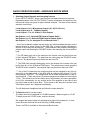
Front Panel View
Rear Panel View
3
SELECTING OPERATING MODE
With firmware versions 2.0 and later the ADX-2400N can operate in two distinct modes:
The NORMAL mode is used for general-purpose transmission and distribution
applications. In this mode the units offer 24 channels of transmission in both directions,
using standard-latency Cobranet format transmission. The ADX-2400N in this mode
transmits three bundles of eight channels each, and receives three bundles of eight
channels each.
Bundle numbers are set manually from the front panel menus.
The DSPs in the unit are used for level control, source selection, and delay.
Transmission latency is approximately 7 milliseconds in each direction (standard mode see next page for low-latency information).
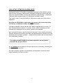
To select NORMAL mode, turn section 3 of the options dipswitch on the subpanel (behind the front panel) OFF and press the Reset button.
The ANNOUNCE BOOTH mode is selected when the ADX-2400 is used to provide the
'head end' or truck end of an ethernet-based announce booth system, using either ADX120 Announce Units, or ADX-140 XLR Interface Frames (or both) to provide a fully selfcontained announce booth system using copper or fiber ethernet as the transmission
medium.
In this mode, the ADX-2400 can support up to four ADX-120s or ADX-140s, in any
combination. The ADX-2400 transmits and receives four bundles of six channels each.
The transmission utilizes the Cobranet 'low-latency' mode, and results in a path latency
of 2.2 milliseconds, analog to analog.
The DSPs are reconfigured to provide routing matrices for IFB source selection, PGM
source selection, Talkback output configuration, and 4-wire port assignments for the PL
channels.
Bundle numbers are set automatically depending on the assigned system ID numbers
for the remote devices (ADX-120, ADX-140).
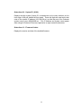
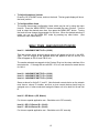
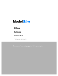
To select ANNOUNCE BOOTH mode, turn section 3 of the options dipswitch on
the sub-panel (behind the front panel) ON and press the Reset button.
Options Dipsw ^
^ System ID Switch
4
^ Reset Button
LOW-LATENCY OPERATION IN NORMAL MODE
Starting with Version 3.0 firmware, it is possible to operate the ADX-2400N in normal
mode, but with low-latency transmission. Low-latency transmission reduces the path
delay from one ADX-2400N to another ADX-2400N from approximately 7 milliseconds
(standard mode) to approximately 2.5 milliseconds (low-latency mode).
This mode is useful if using ADX-2400's for IFB returns or some other delay-critical
application.
Note that the ADX-2400Ns on both ends must operate in the same mode (either
low-latency or standard) for audio transmission to occur.
Low-latency operation requires that the ADX-2400N be equipped with a revision J or
later Cobranet interface module. If an earlier version module is installed, and fault
message will be displayed, and low-latency operation is not possible.
Also, note that low-latency operation puts more demands on the network performance.
Ethernet switches which operate comfortably with standard-latency operation my not be
satisfactory with low-latency operation. Gigabit ethernet switches are recommended to
insure satisfactory operation.
To configure the ADX-2400N for low-latency operation, turn on Options
Dipswitch #4, and press Reset.
An 'LL' indicator will be present in the upper right corner of the display, indicating lowlatency operation is selected.
Note that low-latency operation is automatically selected when in Announce Booth
mode, and switch 4 will have no effect.
5
QUICK OPERATION GUIDE - NORMAL MODE
To Select Output Channel (or Channels) to Adjust
Press ‘OUTPUT SELECT’ button, and turn knob until desired channel is selected.
Repeated presses of the 'OUTPUT SELECT' button will advance the selection to the
first channel of the next group of eight individual channels, or to the next group
selection. The order of the channel selection is as follows:
Local (AES) Output 1 through 24 (Individual Outputs)
Local Outputs 1-8 (Group)
Local Outputs 9-16 (Group)
Local Outputs 17-24 (Group)
All Local Outputs (Group)
Net (Transmitted to Ethernet) Output 1 through 24 (Individual Outputs)
Net Outputs 1-8 (Group)
Net Outputs 9-16 (Group)
Net Outputs 17-24 (Group)
All Net Outputs (Group)
Note that if a group of outputs is selected, any setup adjustments (source, level,
delay) will be applied to all output channels within that group.
The VU Meter and Headphone Jack will follow the output selection. If a group is
selected, there will be no VU display or headphone output.
To Select Source (for current output or group of outputs)
Press 'SOURCE' button. It will light, and the currently-selected source for the
selected output will be displayed. The sources available for each output are as
follows, and can be selected by turning the knob.
SILENCE
LOCAL INPUT
NET INPUT
888HZ TONE
560 HZ TONE
The output will be muted
The output will be fed by the corresponding local AES input
The output will be fed by the corresponding network receiver
The output will be fed by the internal 888 Hz tone generator
The output will be fed by the internal 560 Hz tone generator
You may enable a ‘stereo summing’ mode by selecting any of the following choices,
which follow the above sources in the menu list. In these modes, the selected
source will be combined with the selected source for the other channel in the
even/odd pair; e.g., channels 1 and 2, channels 3 and 4, etc. When a ‘something +
mix’ source is selected, the mixed signal is reduced by 6 dB.
SILENCE + MIX
LOCAL + MIX
NET INPUT + MIX
888HZ TONE + MIX
560 HZ TONE +MIX
The output will silence mixed with the other channel of the pair
The local AES input mixed with the other channel of the pair
The network receiver mixed with the other channel of the pair
888Hz tone mixed with the other channel of the pair
560Hz tone mixed with the other channel of the pair
6
To Adjust Level (for current output or group of outputs)
The output level can be adjusted in 0.25 dB increments. Maximum gain is +12 dB.
To adjust, press the 'LEVEL' button, and turn the knob.
To Adjust Delay (for current output or group of outputs)
The delay of each output can be independently adjusted from zero delay through
680 milliseconds, which corresponds to more than 20 frames at 30 frames/sec. The
delay is adjusted by first pressing the 'DELAY' button, then turning the knob to
adjust. Note that the displayed units (milliseconds or frames) is selected in the
menu.
To Adjust Headphone Volume
Press the 'HP VOLUME' button, and turn the knob. The bar graph display will show
the knob 'position'.
To Configure Menu Items
The system has several configuration items which may be set by using the menu
function. Press the 'MENU SELECT' button to enable the menu function. Turn the
knob to select the desired menu item, then press the 'MENU SET' button. Turning
the knob will now change the parameter for this item. When the desired selection is
made, you can exit the MENU SET mode by pressing any other button. (See
section on menu items below).
MENU ITEMS - NORMAL MODE
Item 01 – RX 1-8 Bundle (000-999)
Packet assignment for network receiver 1, which corresponds to audio channels (net
inputs) 1-8. This number should be set to match the bundle number of the
transmitter in another unit which is sending audio to this receiver. Note that bundle
000 is inactive (off). Bundles 001-255 are broadcast bundles, and should only be
used if one transmitter is sending to more than one receiver. Bundles 256-999 are
unicast bundles, and should be used for normal point-to-point, one transmitter/one
receiver operation.
Item 02 – RX 9-16 Bundle (000-999)
Packet assignment for network receiver 2, which corresponds to audio channels (net
inputs) 9-16.
Item 03 – RX 17-24 Bundle (000-999)
Packet assignment for network receiver 3, which corresponds to audio channels (net
inputs) 17-24.
7
Item 04 – TX 1-8 Bundle (000-999)
Packet assignment for network transmitter 1, which corresponds to audio outputs
NET 01 – NET 08.
Item 05 – TX 9-16 Bundle (000-999)
Packet assignment for network transmitter 2, which corresponds to audio outputs
NET 09-NET 16.
Item 06 – TX 17-24 Bundle (000-999)
Packet assignment for network transmitter 3, which corresponds to audio outputs
NET 17 – NET 24.
Item 07 – Conductor Priority (Low – Normal – High)
This item determines the priority of this unit to operate as the 'sync generator' for the
Ethernet audio network. It should normally be set to 'Normal' unless you specifically
want this unit to be the conductor, in which case it could be set to high. If set to
high, this unit will be the conductor unless another is also set high. In the case
where more than one unit has equal priority, the first unit active will assume the
conductor role. This selection isn't too important, since the network will quickly renegotiate a new conductor if the current conductor were to fail or be turned off.
Item 08 – Delay Units (Milliseconds – Frames (30) – Frames (25))
This item selects the units used to display the delay values. It only affects the
display, and if set to Frames, saves the user having to do the arithmetic in his head.
It assumes 33 milliseconds for 30 Frames/sec, and 40 milliseconds for 25
Frames/sec.
Item 09 - GPI Mode = (Off, Master)
For future or special application use. Should be set to 'Off' normally.
Item 10 - GPI 1/3 Device ID = (00-99)
Item 11 - GPI 2/4 Device ID = (00-99)
For future or special application use. Should be set to '00' normally.
8
Item 12 - Save To User Config 1
Item 13 - Save To User Config 2
Item 14 - Save To User Config 3
There are three user setup files, and these three menu items allow the current
configuration to be saved to these user config files. To save configuration settings,
select the appropriate item number and press 'MENU SET'. The configuration will
be saved to the selected file.
Note that 20 seconds after any configuration change, the current settings are
automatically saved to a default configuration, which will be automatically loaded at
power-up. This is separate from the User Configuration files above.
Item 12 - Recall User Config 1
Item 13 - Recall User Config 2
Item 14 - Recall User Config 3
Selecting one of these three items and pressing 'MENU SET' will cause the settings
previously saved in the selected User Config file to be recalled.
Item 15 - Recall Standard Config
Pressing the 'MENU SET' button will recall a 'standard configuration'. All levels will
be set to unity, all delays will be set to zero, all local outputs will have their sources
set to NET, and all network outputs will have their sources set to LOCAL. All bundle
numbers will be set to 000.
The following items are STATUS items, and are only to display status
information. They may not be directly changed by the user.
Status Item 01 – NET RX 1 Status (Active or Idle)
Displays ACTIVE status if data is being received by network receiver 1. This
receiver corresponds to net inputs 1-8. Note that the data could be silence; an
active receiver doesn’t necessarily mean that there is audio present.
Status Item 02 – NET RX 2 Status (Active or Idle)
Same for receiver 2, which corresponds to net inputs 9-16.
9
Status Item 03 – NET RX 3 Status (Active or Idle)
Same for receiver 3, which corresponds to net inputs 17-24.
Status Item 04 – NET TX 1 Status (Idle or Number of Receivers)
If this transmitter is turned off (bundle = 000), or if it is set to a unicast bundle
(bundle = 256-999) with no corresponding receiver present, this status item will
indicate IDLE status. The transmitter is not putting any data on the network.
Otherwise, it will indicate the number of receivers listening to this transmitter. The
network only counts receivers up to four, so if there are more than three receivers
present, the status item will report “>3 Rcvrs”.
Note that unless the status is IDLE, the transmitter is putting data on the network. If
assigned as a broadcast bundle (001-255), the status could be “ 0 Rcvrs “, if no
receivers were listening to this bundle number. The data is still present on the
network.
Net TX 1 corresponds to net outputs 1-8.
Status Item 05 – NET TX 2 Status (Idle or Number of Receivers)
Same as above for net outputs 9-16.
Status Item 06 – NET TX 3 Status (Idle or Number of Receivers)
Same as above for net outputs 17-24.
Status Item 07 – Conductor Status (Another Unit or This Unit)
Indicates if the network conductor ('sync generator') is this unit or not.
Status Item 08 – PCB Temperature ( degrees Celsius)
Indicates temperature of sensors on main PCB. Normal temperature is in the 40-48
degree range. A high temperature indication might indicate a fan failure, and will
cause a fault message to be displayed if the temperature exceeds 55 degrees C.
(continued)
10
Status Item 09 – System ID (00-99)
Displays two-digit system (frame) ID, as determined by the rotary switches on the
front edge of the pcb, behind the front panel. These two digits are used as the last
octet of the network IP address (192.168.100.xx), and the last part of the Cobranet
system name (Lance ADX2400N-xx). This IP address and system name appear
when using the Cobranet 'Discovery' application to report network node status.
Status Item 10 – Firmware Version
Displays the version and date of the installed firmware.
11
System Configuration In Normal Mode
The ADX-2400 is designed to provide delay, level control and distribution for effects
or commentary audio. The system can be used for stand-alone delay of 24 audio
channels, or can be used to transmit and receive audio signals via a standard
Ethernet data network (24 transmit and 24 receive channels simultaneously), or the
combination of both functions.
The system is 'output oriented'. It can be thought of as having 48 outputs: 24 'local'
outputs on the rear panel, and 24 'network' outputs which are sent to the Ethernet
network. Each of these 48 outputs can be set up as follows:
SELECT SOURCE:
SILENCE, LOCAL INPUT, NETWORK INPUT, TONE1 (888HZ), or TONE2 (560Hz),
(or the one of the above sources mixed with the source from the other channel of the
even-odd pair, for stereo summing)
ADJUST LEVEL:
OFF to +12DB in 0.25DB steps
ADJUST DELAY:
0 milliseconds to 680 milliseconds (20 frames in 30fps), in 1 millisecond steps
The configuration of each output is independent, although you can select groups or
all to save setup time if you are setting them all to be the same.
The unit should also be thought of as having 48 inputs: 24 AES inputs on the back
panel, and 24 inputs from the network receivers.
Application Examples:
For stand-alone delay, all outputs would be set to 'local input', and level and delay
adjusted as desired. The network tx/rx would not be used.
For transmitting effects to another truck, and inserting delay in the path: The network
outputs would be set to 'local inputs', routing the analog audio inputs to the network
transmitters. Delay and level adjustment could be done as desired. The local outputs
could also be set to 'local inputs', providing an independent local delay. Alternatively,
the local outputs could be set to 'network inputs', and these used as network
receivers for audio coming back from the other truck.
Distribution of effects or other audio to multiple trucks could be accomplished by
transmitting the audio using broadcast bundles, and receiving at each point of use.
Delay and levels could all be adjusted independently at the receivers, or globally at
the network transmitters.
12
Saving and Recalling Configurations
The menu settings and the source, level, and delay settings are stored automatically
after 20 seconds of panel inactivity in a 'default' flash memory. This is the memory
which is restored automatically when the unit is first powered up.
You may also save configurations in three user memories. Select the desired
memory by selecting Menu Item 09-11. When the 'MENU SET' button is pressed,
the current configuration will be saved to the selected user memory.
To recall one of these user memories, select the desired memory by chosing menu
item 12-14. When the 'MENU SET' button is pressed, all config data saved in that
user memory will be recalled and immediately applied to the audio hardware.
Factory default or 'standard' configuration may be recalled by selecting menu item
15 and pressing 'MENU SET'. It may also be recalled on power up or reset by
turning on options dipswitch section 1.
The factory default sets all levels to unity, all delays to zero, local output sources to
net inputs, and net outputs to local inputs. All bundle numbers are set to zero.
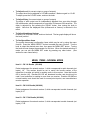
Dipswitch functions (Ver 5.0 firmware)
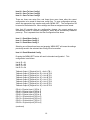
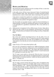
There is an Options Dipswitch located behind the front panel, accessible by
removing the thumbscrews on either side of the front panel.
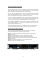
Section 1 - Causes factory defaults to be loaded at power-up. Normally OFF.
Section 2 - Unused
Section 3 - Puts ADX2400N into 'Announce Booth Mode' when ON.
Section 4 - Selects Low-Latency operation in Normal Mode when ON.
Section 5 - Selects older remote control protocol for use with early ADX120/140s.
Section 6 - Unused
Section 7 - Locks Channel Setups (level, source, delay) when ON.
Section 8 - Locks Menu Selections when ON.
Options Dipsw ^
^ System ID Switch
13
^ Reset Button
QUICK OPERATION GUIDE - ANNOUNCE BOOTH MODE
Selecting Output Channels and Assigning Sources
Press ‘OUTPUT SELECT’ button, and turn knob until desired channel is selected.
Repeated presses of the 'OUTPUT SELECT' button will advance the selection to the
first channel of the next group of eight individual channels. The order of the channel
selection is as follows:
Local Outputs 1 to 8 - Microphone Outputs (A1, A2, B1, B2, etc.)
Local Outputs 9 to 16 - Talkback Outputs*
Local Outputs 17 to 24 - 4-Wire PL Port Outputs
Net Outputs 1 to 8 - Selected IFB Feeds to Remote Units**
Net Outputs 9 to 16 - Selected PGM Feeds to Remote Units***
Net Outputs 17 to 24 - Assigned PLs to Remote Units****
* Any of the 8 talkback outputs may be fed by any individual talkback buttons on the
remote devices (or inputs 3 and 4 of the ADX-140), or various mixed combinations.
Silence or tones may also be selected. These selections are made by selecting the
desired output and pressing the 'SOURCE' button, then selecting the source with the
knob.
** The IFB feeds going out on the network to the remote units may be fed from any
of the 8 physical IFB inputs. The selections are made using the 'SOURCE' button,
as above. Any physical input may feed more than one IFB.
*** The PGM (Non-Interrupt) feeds going out on the network to the remote units may
be fed from any of the 8 physical PGM inputs. The selections are made using the
'SOURCE' button, as above. Any physical input may feed more than one PGM.
**** Any of the PL channels at the remote devices may be assigned to any of the 4wire ports on the back panel of the ADX-2400 by selecting Net Outputs 17 to 24,
then pressing 'SOURCE'. The assignments will be made automatically for both 4wire directions. (That's why there is no source assignment available for local outputs
17-24). The internal 4-wire matrix takes care of all necessary mix-minus generation
for the PLs automatically, so any remote device PLs assigned to the same 4-wire
port will be able to talk to each other. This is similar to the 'party-line' function in the
Telex Adam system, but it happens automatically.
The VU Meter and Headphone Jack will follow the output selection.
To Adjust Level (for current output)
The output level can be adjusted in 0.25 dB increments. Maximum gain is +12 dB.
To adjust, press the 'LEVEL' button, and turn the knob.
We suggest that output levels only be adjusted in special circumstances. In most
cases the levels should all be left in the Unity (0.00dB) settings.
There is no DELAY available in the Announce Booth mode.
14
To Adjust Headphone Volume
Press the 'HP VOLUME' button, and turn the knob. The bar graph display will show
the knob 'position'.
To Configure Menu Items
The system has several configuration items which may be set by using the menu
function. Press the 'MENU SELECT' button to enable the menu function. Turn the
knob to select the desired menu item, then press the 'MENU SET' button. Turning
the knob will now change the parameter for this item. When the desired selection is
made, you can exit the MENU SET mode by pressing any other button. (See
section on menu items below).
MENU ITEMS - ANNOUNCE BOOTH MODE
Item 01 – ANNOUNCE UNIT A ID = (00-99)
This item selects which physical remote device will appear as Unit A in the ADX2400. The mic outputs of the selected device will appear as Mic A1 and A2, the
IFBs will appear as IFB A1 and IFB A2, etc.
The number selected corresponds to the System ID set on the rotary switches of the
remote device. 01 through 99 are valid IDs. 00 is off, and selects no remote device
for Unit A.
Item 02 – ANNOUNCE UNIT B ID = (00-99)
Item 03 – ANNOUNCE UNIT C ID = (00-99)
Item 04 – ANNOUNCE UNIT D ID = (00-99)
Same as above for Units B, C, and D. Note that each remote device on the network
must have a unique ID number, and that a given remote device should only be
assigned once; in other words don't assign the same unit to be both Unit A and Unit
B.
Item 05 - GPI Mode = (Off, Master)
For future or special application use. Should be set to 'Off' normally.
Item 06 - GPI 1/3 Device ID = (00-99)
Item 07 - GPI 2/4 Device ID = (00-99)
For future or special application use. Should be set to '00' normally.
15
Item 08 - Save To User Config 1
Item 09 - Save To User Config 2
Item 10 - Save To User Config 3
There are three user setup files, and these three menu items allow the current
configuration to be saved to these user config files. To save configuration settings,
select the appropriate item number and press 'MENU SET'. The configuration will
be saved to the selected file. Menu settings and Source assignments are saved.
Note that 20 seconds after any configuration change, the current settings are
automatically saved to a default configuration, which will be automatically loaded at
power-up. This is separate from the User Configuration files above.
Item 11 - Recall User Config 1
Item 12 - Recall User Config 2
Item 13 - Recall User Config 3
Selecting one of these three items and pressing 'MENU SET' will cause the settings
previously saved in the selected User Config file to be recalled.
Item 14 - Recall Standard Config
Pressing the 'MENU SET' button will recall a 'standard configuration'. This
configuration is as follows:
Unit A ID = 01
Unit B ID = 02
Unit C ID = 03
Unit D ID = 04
Talkback Output 1 [Physical Out 9] = Unit A TB 1
Talkback Output 2 [Physical Out 10] = Unit A TB 2
Talkback Output 3 [Physical Out 11] = Unit B TB 1
Talkback Output 4 [Physical Out 12] = Unit B TB 2
Talkback Output 5 [Physical Out 13] = Unit C TB 1
Talkback Output 6 [Physical Out 14] = Unit C TB 2
Talkback Output 7 [Physical Out 15] = Unit D TB 1
Talkback Output 8 [Physical Out 16] = Unit D TB 2
IFB A1 = Physical Input 1 [IFB In 1]
IFB A2 = Physical Input 2 [IFB In 2]
IFB B1 = Physical Input 3 [IFB In 3]
IFB B2 = Physical Input 4 [IFB In 4]
IFB C1 = Physical Input 5 [IFB In 5]
IFB C2 = Physical Input 6 [IFB In 6]
IFB D1 = Physical Input 7 [IFB In 7]
IFB D2 = Physical Input 8 [IFB In 8]
(continued)
16
PGM A1 = Physical Input 9 [PGM In 1]
PGM A2 = Physical Input 10 [PGM In 2]
PGM B1 = Physical Input 11 [PGM In 3]
PGM B2 = Physical Input 12 [PGM In 4]
PGM C1 = Physical Input 13 [PGM In 5]
PGM C2 = Physical Input 14 [PGM In 6]
PGM D1 = Physical Input 15 [PGM In 7]
PGM D2 = Physical Input 16 [PGM In 8]
PL A1 = 4-Wire Port 1 [Physical Input/Output 17]
PL A2 = 4-Wire Port 2 [Physical Input/Output 18]
PL B1 = 4-Wire Port 3 [Physical Input/Output 19]
PL B2 = 4-Wire Port 4 [Physical Input/Output 20]
PL C1 = 4-Wire Port 5 [Physical Input/Output 21]
PL C2 = 4-Wire Port 6 [Physical Input/Output 22]
PL D1 = 4-Wire Port 7 [Physical Input/Output 23]
PL D2 = 4-Wire Port 8 [Physical Input/Output 24]
All Levels set to Unity [0.00 dB]
Please see the detailed Configuration section of this manual for more information.
The following items are STATUS items, and are only to display status
information. They may not be directly changed by the user.
Status Item 01 – Unit A RX Status (Active or Idle)
Displays ACTIVE status if data is being received by network receiver 1. This
receiver is used for audio signals coming from the remote device assigned as Unit
A.
Status Item 02 – Unit B RX Status (Active or Idle)
Same for receiver 2, audio signals coming from the Unit B remote device.
Status Item 03 – Unit C RX Status (Active or Idle)
Same for receiver 3, audio signals coming from the Unit C remote device.
Status Item 04 – Unit D RX Status (Active or Idle)
Same for receiver 4, audio signals coming from the Unit D remote device.
Status Item 05 – PCB Temperature ( degrees Celsius)
Indicates temperature of sensors on main PCB. Normal temperature is in the 40-48
degree range. A high temperature indication might indicate a fan failure, and will
cause a fault message to be displayed if the temperature exceeds 55 degrees C.
(continued)
17
Status Item 06 – System ID (00-99)
Displays two-digit system ID for this ADX-2400, as set by rotary switches on the subpanel.
Status Item 10 – Firmware Version
Displays the version and date of the installed firmware.
18
System Configuraton In Announce Booth Mode
Configuration of the system takes place both in the ADX-2400 and in the remote
devices (ADX-120/140) themselves. This configuration is all done from the ADX2400 front panel.
There are three catagories of configuration:
1. The ADX-2400 Menu Configuration
This is where the remote devices are assigned to be Units A, B, C, and D.
There are no other config items except for gpis, saving and recalling the
configurations to/ from user memory files, and some status displays.
2. The ADX-2400 Channel Setup
This is where 'truck-end' routing assignments are made for the talkback
outputs, IFB and Program paths, and PL ports. These assignments are
made using the OUTPUT SELECT and SOURCE buttons on the ADX-2400.
The LEVEL button also is available to control output levels to both the rearpanel outputs and the outputs sent to the network and thus to the remote
devices. The DELAY function is not available in announce booth mode.
3. The Remote Device menus
Each remote device (ADX-120/140) has an internal menu which may be
accessed remotely via the ADX-2400.
These menus configure the hardware of the remote device itself, and are
specific to the particular model, i.e. the ADX-120 has different options from
the ADX-140 because of differences in their hardware capabilities.
These menus configure such things as preamp gain, phantom power, IFB
output configurations, headset impedence (level), button color, etc.
These remote menu settings are saved in the remote devices themselves,
and will remain associated with a particular device, even if it is moved or has
its system ID reassigned. These settings are not stored in the ADX-2400 at
the truck.
Status of many of the remote configuration items is displayed by LEDs on the
remote devices (rear panel on the ADX-120s, front panel on the ADX-140s).
19
Setting System ID Switches
The System ID switches on each unit allow the system to distinguish one unit from
another. Cobranet bundle numbers and Ethernet IP addresses are automatically
determined based on the System ID Switches.
The System ID switches are two-digit rotary switches on the rear panel of the ADX120 and on the front panel of the ADX-140. The ADX-2400 also has System ID
switches, which are behind the removeable front panel, on the PCB sub-panel.
The range for the switches is from 01 through 99 (00 is not a valid ID). No two
devices may have the same ID number.
Important Note: Version 3.0 and 3.1 firmware required that the tens digit match for
associated devices in order to establish 'control domains'. This was not a good
solution, and this requirement has been eliminated in Version 5 systems. If all
devices have version 5.0 or later firmware, any numbers 01-99 may be used as
system IDs for any devices.
Compatibility: ADX-2400Ns with version 5.0 or later firmware may be used with
earlier ADX-120s or ADX-140s by turning on Dipswitch section 5 on the 2400, and
using IDs for all devices with the first (tens) digit = 0. This is provided as an
emergency or interim operating mode. All devices should be upgraded to version
5.x as soon as practical.
The System ID settings for the ADX-120/140 units become the reference for the
physical unit, and will be used in assigning those units to be A, B, C, and D
designations in the ADX-2400 menus (see next page).
20
Assigning the ADX120 / ADX140 to be Units A, B, C, or D
The announce units must first be assigned to be devices A, B, C, or D in the
ADX2400 menu. To do this, press the MENU button once, and select config items
1, 2, 3, and 4 respectively using the knob. When the desired item is selected, press
the MENU SET button and select the appropriate System ID number for the ADX120
or ADX140 you want to assign. Pressing either SET or MENU will take you back to
the item select mode.
Accessing Remote Menus from the ADX-2400
The configuration items for the ADX-120 and ADX-140 units are accessable from
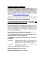
the front panel of the ADX-2400. To access these remote unit menus, double-click
the MENU button on the ADX2400. The display will say: SELECT REMOTE
DEVICE. The MENU button will be flashing to indicate that a remote device is being
accessed.
The menu display will look similar to this:
Select Remote Device
Unit A [01] ADX120-01
The number in the brackets is the System ID assigned in the ADX-2400 for Unit A
(in this example).
If the selected device is present on the network, it's model
number and System ID number will be displayed (ADX120-01 in this example).
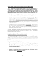
Scroll to the desired assigned device (either A, B, C or D).
Press MENU again. This will access the menu of the remote device, and the menu
might look like this (depending on the type of device and the selected item):
ADX120-01 Config Item 01
Mic 1 Gain=45dB HR>30dB
The configuration and status items may be selected using the knob. Once the
desired item is selected, press the MENU SET button to allow changing that item's
settings. Settings are saved automatically after about 10 seconds of inactivity.
Press either MENU SET or MENU to go back to the item select mode.
When you're done, the easiest way out of any of the menu modes is to just press the
OUTPUT SELECT button. This will cancel all menu modes, and you won't have to
step backwards out of them.
21
ETHERNET NETWORK INFORMATION
The Ethernet transmission uses the Cirrus Audio 'Cobranet' protocol, which is an
industry standard. It is a professional, highly-reliable system which packs audio data
into 'bundles' of 8 (or fewer) channels. The bundles are given numbers from 1 to
999. The first 255 are 'broadcast' bundles which can be received by any number of
receivers, so long as the receiver is set to the same bundle number. The rest are
'unicast' bundles, which will only be received by one receiver at a time. More
Cobranet info at: http://www.cobranet.info/en/support/cobranet/
There are two Audio Network ports on the rear panel of the ADX-2400. These are
redundant network connections, and either may be used. If desired, a redundant
network connection my be established by using the second port. If both are used,
the left-hand connector will be the primary, and the right the backup. If both links
are established, and one is lost, audio will continue uninterrupted.
The simplest network is simply connecting two ADX-series devices together. Note
that this type of connection requires a Crossover Cable, as the ports are not autosensing.
Most networks are established by using standard Ethernet switch(es). The switches
must support Layer 2 traffic. Each ADX unit must be connected to the switch on its
own port. If multiple switches are used, it is desirable for the switches to connect to
each other using gigabit Ethernet. A gigabit Ethernet link allows 700 or more audio
channels to be sent in each direction.
A 100base/T full duplex link allows 72
channels to be sent in each direction.
Switches with built-in fiber connectivity (SFP/GBIC) are readily available and provide
a powerful, inexpensive solution to fiber transmission requirements.
It is recommended that simple hubs not be used, although they will work if total
network traffic is limited to 48 channels (6 bundles total)
The indicators on the audio network ports provide an indication of port status, as
described below:
Yellow Indicator:
Steadily-lit if connector is active. (Does not indicate a link or
audio transmission). Flashing indicates that this unit is the
'conductor' or sync generator for the entire audio network.
Green Indicator:
Steadily-lit indicates an Ethernet link.
packet transmission/reception.
When audio is being transmitted, the normal condition is either:
Yellow On, Green Flashing (this unit not conductor)
or
Yellow Flashing, Green Flashing (this unit is conductor)
22
Flashing indicates
Setting Bundle Numbers (Does not apply in Announce Booth Mode)
The 24 transmit and 24 receive audio channels in the ADX are divided into 8channel groups. These groups are assigned to network channels or 'bundles'.
There are six bundles per ADX unit, three for receive and three for transmit. Each of
these bundles can be assigned a three-digit number from 000 – 999. (Note that the
Cobranet system allows numbers as high as 65000, but they are limited in the ADX2400 to 999).
A bundle assignment of 000 is defined as inactive, and will disable this network
transmitter or receiver. Audio outputs from disabled receivers will be silence.
A bundle assignment in the range 001-255 is a Broadcast Bundle. These
numbers should be used when it is desired that one transmitter be received by
multiple receivers. Note that broadcast bundle data will appear on all network
segments (all switch ports) and can cause network congestion if used when not
required. Use broadcast bundles only when required to avoid unnecessary
traffic on the network.
A bundle assignment in the range 256-999 is a Unicast Bundle. These numbers
are used for normal transmission from one transmitter to one receiver (point to
point). A switch will route this traffic only to the required port and reduce
unnecessary traffic on the network.
The audio transmission will usually follow the bundle assignment almost instantly,
however on occasion there will be a delay of a second or two as the Cobranet
hardware negotiates the connection.
Designing the Network (Please read this section!)
The Cobranet technology is very powerful, and allows for very flexible system
design. It is not without limits, however. It is important to have a full understanding
of how the system operates to avoid network problems, and therefore to avoid audio
problems.
Here are some important things to know:
There are limits to the number of audio channels which may be present on any
given network. The network connection on the rear panel of the ADX-2400 is a
100 Mbit/sec Ethernet connection. As transmitted by the ADX, each audio
channel requires approximately 1 Mbit/sec of bandwidth, so each bundle (8
Channels) requires 8 Mbit/sec.
Because of the additional control and timing data, each 100 Mbit/sec network
segment can handle a maximum of 9 bundles.
23
Exceeding this bandwidth limit will cause dropouts in the audio, and in severe
cases may cause other problems such as sync and control problems.
An Ethernet switch or switches, which generally form the network, can partition
the traffic so that bundles only go the receivers which are listening to them.
Since each ADX frame only has three receivers, this can eliminate network traffic
problems if each bundle is a unicast bundle (one transmitter to one receiver).
The switch will route the traffic only to the required receiver.
Broadcast bundles (bundle numbers 001-255) can NOT be isolated by the
Ethernet switch. They will appear on ALL network segments, regardless of
receivers. You should use broadcast bundles only when required, and be aware
that they add to the traffic on all segments of the network.
The bottleneck for network will usually be the receive side of the network
segments connecting the ADX frames. The network segment connecting to an
ADX frame will see all unicast bundles being received by that frame, plus ALL
broadcast bundles on the network. This total number of bundles can not exceed
10 (9 is better). (This number does not include bundles being transmitted by this
frame).
The broadcast bundles are a very powerful feature, in that they allow very
convenient and inexpensive distribution of lots of audio signals. Using broadcast
bundles can really clog up the network, however, so be aware of the tradeoffs, and
use them only when required.
If the network traffic becomes too heavy, and audio packets are being dropped, the
ADX front panel buttons will flash, and a “NETWORK ERRORS“ warning message
will be displayed.
Some other things to know about the network operation:
Because of the way Ethernet works, the ADX frames can not see their own
transmissions. This means that if you dial a transmitter and receiver (in the
same ADX unit) up to the same bundle number, the transmitted audio will NOT
appear on the receiver outputs. Select ‘local’ as the source instead.
Only one ADX receiver can listen to a given unicast bundle. If you assign two
receivers to the same unicast bundle, only the first will output audio. Broadcast
bundles can be repeated on multiple receivers, either in separate frames or in
the same frame (for multiple copies of the same audio).
All audio on the network is 20-bit uncompressed. It takes a fixed amount of
bandwidth, regardless of the audio content.
24
Cobranet 'Discovery' PC Application
Cirrus Logic, the developers of Cobranet, make available on their website a nice PC
application called 'Cobranet Discovery', or 'Disco'. It can be downloaded and
installed on any PC running Windows XP. It allows the computer to be attached to
the audio network and provides a variety of information about the attached network
devices. Documentation is available on their website: www.cobranet.info, or at
www.lancedesign.com.
The PC TCP/IP network properties must be set for a fixed IP address (not DHCP),
and a subnet mask. The firmware in the ADX-2400s sets their IP addresses to
192.168.100.xx, where xx is the System ID, set by the rotary switches on the PCB
behind the front panel.
I recommend setting the PC IP Address to 192.168.100.200, although any number
001 to 254 is fine for the last octet provided the address doesn't conflict with the
addresses of any ADX-2400s on the network. The subnet mask should be set to
255.255.255.0.
25
Installation
The ADX-2400N is designed to be installed in a standard 19" equipment rack.
There is a cooling fan on the rear panel which draws air in through the sides of the
cabinet and exhausts hot air through the rear panel. The unit should not be installed
in such a way as to block the vents on the side panels, or air flow from the rear panel
fan.
The unit is designed to operate on 95-250 volts AC, 50 or 60 Hz. The power
supplies are wide-range switching supplies, so no voltage selection needs to be
made. Dual power supplies are installed for redundancy.
Power consumption is approximately 25 watts.
The analog audio connections are made through six 25-pin female D-sub
connectors, wired to the industry-standard Tascam DA-88/Protools standard. Prewired jackfields and breakout cables are available from Audio Accessories
(www.patchbays.com) and other vendors.
The audio format is balanced, +4db nominal. The source impedance of the outputs
is approximately 50 ohms. The input impedance is approximately 25K ohms. The
system is intended to be used in a modern constant-voltage system. The outputs
may be terminated in 600 ohms if necessary, with a loss in level of about 0.75 dB.
This termination will increase power dissipation in the output amplifiers, and is not
recommended unless necessary for system consistency.
The audio cables should be supported in such a way as to prevent weight being
applied to the rear of the ADX-2400. The rack mounting flanges are sufficient to
support the unit itself, but not additional loading of the heavy I/O cables. Support
bars under the rear of the frame are recommended.
The Ethernet 'Audio Network' ports (one or both) should be connected to the
network with standard CAT5 RJ-45 cables, following normal IT practice. The ports
are 100/baseT Ethernet. The connectors on the ADX-2400 are wired with the same
pinout as normal PC ports, and are not auto direction sensing. If connecting two
ADX units together without a switch, a crossover cable must be used.
It is not possible to 'daisy-chain' units together. The two ports do not function as
'loop-through'. Each unit should be connected to a separate switch port.
The maximum length for 100/baseT Ethernet on copper is 100 meters. For longer
runs there must be a repeater (switch) or media converter (fiber) in the path. See
the Cobranet website (www.cobranet.info) for more information.
26
Reliability Considerations
Since on-air audio is often handled by the ADX systems, reliability is of primary
concern. The ADX-series products are designed with highest-quality components
and conservative ratings so as to be as reliable as possible.
In addition, after manufacture, the ADX products undergo an extensive burn-in
process which includes power and thermal cycling to attempt to precipitate out any
early-life failures.
Even with these precautions failures are not impossible, and in addition there are
other components to the system such as Ethernet switches which must also be
considered in evaluating the overall reliability question.
Here are some thoughts on insuring a reliable on-air system:
Provide a spare announce box and headset. This practice has been going
on for decades with analog systems, and it's still a good idea. It protects
against failure of the ADX-120 and the headset.
Use the ADX-800 to provide power for the ADX-120s. This unit contains
redundant power supplies and will provide highly-reliable power, even in the
event of the failure of one of the supplies.
Insure a reliable AC power source in the remote location for the ADX units
and for the Ethernet switch. If there is any question about the reliability of
the AC supply you might consider using a small UPS power supply to provide
battery backup. A small 500 watt unit intended for personal computer use
will provide a half-hour of typical operation in the event of power failure.
Use reliable Ethernet hardware such as switches, fiber GBICs, etc. Burn in
new switches for a few days before putting them on the air. Keep all
Ethernet cables and fiber in good condition.
Many switches have two fiber GBIC ports available. If the switches support
'trunking' or 'port aggregation' and most do, two fiber runs could be
connected between switches, thus protecting against fiber and GBIC failure.
Consider using standard IT methods for providing a fault-tolerant network, if
practical and warranted. Redundant switches and parallel networks may be
used. ADX-120s and ADX-140s with version 5.0 or later firmware include a
sophisticated method of selecting the active ethernet connection based on
both link status and the presence of audio packets. Contact Lance Design
for more information.
27
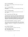
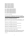
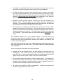
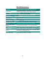
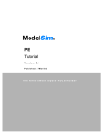
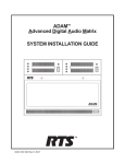
Physical Inputs and Outputs in Announce Booth Mode
Outputs:
Out 1
Out 2
Out 3
Out 4
Out 5
Out 6
Out 7
Out 8
Mic
Mic
Mic
Mic
Mic
Mic
Mic
Mic
Out
Out
Out
Out
Out
Out
Out
Out
9
10
11
12
13
14
15
16
Talkback
Talkback
Talkback
Talkback
Talkback
Talkback
Talkback
Talkback
Out
Out
Out
Out
Out
Out
Out
Out
17
18
19
20
21
22
23
24
4-Wire
4-Wire
4-Wire
4-Wire
4-Wire
4-Wire
4-Wire
4-Wire
A1 Out
A2 Out
B1 Out
B2 Out
C1 Out
C2 Out
D1 Out
D2 Out
Inputs:
Input 1
Input 2
Input 3
Input 4
Input 5
Input 6
Input 7
Input 8
IFB
IFB
IFB
IFB
IFB
IFB
IFB
IFB
Input
Input
Input
Input
Input
Input
Input
Input
9
10
11
12
13
14
15
16
PGM
PGM
PGM
PGM
PGM
PGM
PGM
PGM
Input
Input
Input
Input
Input
Input
Input
Input
17
18
19
20
21
22
23
24
4-Wire
4-Wire
4-Wire
4-Wire
4-Wire
4-Wire
4-Wire
4-Wire
In
In
In
In
In
In
In
In
Output
Output
Output
Output
Output
Output
Output
Output
PL
PL
PL
PL
PL
PL
PL
PL
Port
Port
Port
Port
Port
Port
Port
Port
1
2
3
4
5
6
7
8
In
In
In
In
In
In
In
In
(ADX120 Hdst Mic; ADX140 Input 1)
(ADX120 Rear Panel; ADX140 Input 2)
(Each physical Talkback output may be fed
by any of the Talkback paths from the ADX120s, Inputs 3 and 4 from the ADX-140s,
or various mixes)
Out
Out
Out
Out
Out
Out
Out
Out
(Each PL channel at the ADX-120/140s
may be assigned to any of the 4-wire
ports.)
(Each IFB output at the ADX120/140s may be fed
from any if the eight physical IFB inputs)
1
2
3
4
5
6
7
8
PL
PL
PL
PL
PL
PL
PL
PL
1
2
3
4
5
6
7
8
1
2
3
4
5
6
7
8
(Each PGM output at the ADX120/140s may be fed
from any of the eight physical PGM inputs)
Port
Port
Port
Port
Port
Port
Port
Port
1
2
3
4
5
6
7
8
In
In
In
In
In
In
In
In
(Input side of 4W PL Interface. See above)
28
ADX-2400N Specifications
24 Balanced Analog. +4 dB nominal, +24 dBv max. D-25F
connectors wired to Tascam DA-88 / Protools standard
24 Active Balanced Analog. +4 dB nominal, +24 dBv max. D-25F
Local Outputs
connectors wired to Tascam DA-88 / Protools standard
Freq Response
20-20KHz
THD+Noise
<0.05% (<0.005% for Rev 3 hardware)
Signal/Noise
>100 dB below peak level, bandwidth-limited to 25KHz
A-D and D-A Conversion
24-bit
Output Impedance
Approx. 50 Ohms
Input Impedance
Approx. 25K Ohms
Digital Processing and Delay 24-bit uncompressed
Cobranet Transmission
20-bit uncompressed
Sample Frequency
48 kHz
Adjustable Delay Range
0 milliseconds to 680 milliseconds (>20 frames at 30 fps)
Minimum Delay (analog in to
1 millisecond (0.55 milliseconds for Rev 3 hardware)
analog out)
Minimum Delay (through
6.5 milliseconds Normal Mode, 2.25 ms Annc Booth Mode
Ethernet)
Headphone Jack
1/4" TRS (Stereo) follows Output selection, Low impedance
Menu
Selects Cobranet bundle numbers (address), config store/recall
Remote Control
Ethernet port (100baseT) separate from Audio Network.
Conventional VU ballistics (300ms), -20 to +3.5 dB scale, follows
VU Meter
Output selection. Scale mark at 0 VU.
Display
2x24 VFD
Power Requirements
95 to 250 Volts AC, 50-60 Hz, <30 Watts
Local Inputs
29
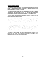
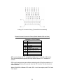
Lance Design ADX-2400N Analog Pinout (Inputs and Outputs)
Audio
Channel
CH 1 +
CH 1 CH 1 SHLD
CH 2 +
CH 2 CH 2 SHLD
CH 3 +
CH 3 CH 3 SHLD
CH 4 +
CH 4 CH 4 SHLD
CH 5 +
CH 5 CH 5 SHLD
CH 6 +
CH 6 CH 6 SHLD
CH 7 +
CH 7 CH 7 SHLD
CH 8 +
CH 8 CH 8 SHLD
D-25 Pin
24
12
25
10
23
11
21
9
22
7
20
8
18
6
19
4
17
5
15
3
16
1
14
2
Audio
Channel
CH 9 +
CH 9 CH 9 SHLD
CH 10 +
CH 10 CH 10 SHLD
CH 11 +
CH 11 CH 11 SHLD
CH 12 +
CH 12 CH 12 SHLD
CH 13 +
CH 13 CH 13 SHLD
CH 14 +
CH 14 CH 14 SHLD
CH 15 +
CH 15 CH 15 SHLD
CH 16 +
CH 16 CH 16 SHLD
D-25 Pin
24
12
25
10
23
11
21
9
22
7
20
8
18
6
19
4
17
5
15
3
16
1
14
2
Audio
Channel
CH 17 +
CH 17 CH 17 SHLD
CH 18 +
CH 18 CH 18 SHLD
CH 19 +
CH 19 CH 19 SHLD
CH 20 +
CH 20 CH 20 SHLD
CH 21 +
CH 21 CH 21 SHLD
CH 22 +
CH 22 CH 22 SHLD
CH 23 +
CH 23 CH 23 SHLD
CH 24 +
CH 24 CH 24 SHLD
6 FEMALE CONNECTORS ON CHASSIS [INPUT AND OUTPUTS]
30
D-25 Pin
24
12
25
10
23
11
21
9
22
7
20
8
18
6
19
4
17
5
15
3
16
1
14
2
Analog I/O Connector Pairing (Tascam/Protools standard)
Remote Control Connector Pinout (Serial Number 254 and later)
Connector is RJ-45 Female
Pin # Function
1
GPI 1
2
GPI 2
3
+5 Volts
4
Ground
5
RS232 Data In (RX)
6
RS232 Data Out (TX)
7
GPI 3
8
GPI 4
GPIs used as inputs are TTL-compatible, pulled up to +5 volts with a 5K resistor.
They should be pulled to ground with a dry switch closure or O.C. transistor to
activate
GPIs used as outputs are open-collector transistors with a 5K pull-up resistor to +5
volts. These transistors pull to ground when the GPI is active. Current should not
exceed 200 Ma.
When ADX-2400 is in Master GPI mode, GPIs 1 and 2 are outputs, and GPIs 3 and
4 are inputs.
31
blank page
32