1
MGP Series Setup Guide
The MGP Series are multi-window video signal processors that can display
multiple video sources on a single screen in picture-in-picture or picture-bypicture format. The processors can switch among inputs as well as picture
controls and presets. The available models are listed below. The MGP 464
models display up to four windows; the MGP 462xi models display one or two.
•
MGP 464/MGP 462xi — Standard models with BNC input connectors that accept RGB, component video,
S-video, or composite video
•
MGP 464 DI/MGP 462xi DI — An MGP 464/462xi with a DVI input card installed, providing four DVI input
connectors.
•
MGP 464 HD-SDI/MGP 462xi HD-SDI — An MGP 464/462xi with two HD-SDI inputs and two DVI inputs.
•
MGP 464W/MGP 464W DI — Designed for WindoWall™ video wall systems and available in sets of two or
three processors. These models have no front panel controls and are controllable only via software. Each MGP
displays up to four windows.
This guide provides procedures for installing all
MGP 464 and MGP 462xi models, and for configuring all
models except the MGP 464W series. To configure the
MGP 464W models (done via software only), refer to the
WindoWall Console help file or the WindoWall Console
Quick Reference card.
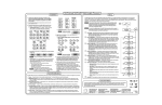
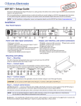
Installation
1.
Install the four rubber feet on the bottom of the
MGP, or mount the unit using the supplied rack
mounting brackets.
MBD 249
2.
Turn off power to the input and output devices, and
remove the power cords from them.
3.
Connect the input sources to the MGP's BNC, DVI,
and/or HD-SDI input connectors. The inputs can
accept the following signal types:
2U Rack Mounting
Bracket (Use four
lower holes.)
Rack mounting the MGP
RGB/HD/video inputs 1, 2, 3, and 4 — RGB, component video, S-video, or composite video (fully configurable)
1
RGBHV
Video
1
R/R-Y
R/R-Y
G/Y
VID
H/HV
G/Y
VID
B/C
B-Y
V
B/C
B-Y
RGBS or
RGBcvS
Video
H/HV
V
1
RGsB or
Component
Video
R/R-Y
1
S-Video
R/R-Y
1
Composite
Video
R/R-Y
G/Y
VID
H/HV
G/Y
VID
H/HV
G/Y
VID
H/HV
B/C
B-Y
V
B/C
B-Y
V
B/C
B-Y
V
DVI inputs 1, 2, 3, and 4 — These inputs can be used instead of, or in combination with,
analog inputs 1 through 4. (However, the MGP cannot process input from two
different source devices connected to DVI and BNC connectors with the same input
number — for example, input 1— at the same time). The DVI inputs are available
only on the MGP 464/462xi DI and HD-SDI models.
INPUT 1-DVI-D
N Analog is not available on these DVI-I connectors.
HD-SDI inputs 1 and 2 — These inputs can be used instead of, or in combination with,
analog inputs 1 and 2. The HD-SDI inputs are only on the MGP 464/462xi HD-SDI.
INPUT 1-HD-SDI
N Standard definition SDI is not supported on these HD-SDI inputs.
68-1666-01 Rev. B
06 09
MGP Series Setup Guide (cont'd)
DVI Background input — DVI for live background video only (available on all models).
The two or four MGP windows are displayed in front of this DVI image. When
a DVI background is used, the MGP output is locked to the input rate of the DVI
background. This input is not scaled. Analog is not available on this DVI-I connector.
DVI BACKGROUND
N This input connector can be used only to receive the background image. The input is not scaled or
processed. To process DVI input signals, you must use the MGP 464/462xi DI or HD-SDI models.
Virtual inputs (not supported on WindoWall models) —
Component video, S-video, or composite video. These
virtual inputs can be configured via Windows®-based control
software, SIS™ (Simple Instruction Set) commands, or the
embedded Web pages only. In each column of connectors,
you can connect inputs as follows:
Composite
S-video and
Composite
5
5
Three composite video
•
One S-video and one composite video
VID
Y
6
6
6
VID
B-Y
C
VID
B-Y
C
7
7
7
VID
R-Y
VID
R-Y
VID
R-Y
N The S-video input must be connected to the top two BNC
connectors in the column (Y on top, C second).
One interlaced component video (connects to all three BNC connectors in the column)
•
4.
5
VID
Y
VID
Y
VID
B-Y
C
•
Component
DVI-D OUTPUT
Attach an output device to the RGB/YUV BNC connectors (shown below) and/or to the
DVI output connector (shown at right). Analog is not available on this DVI connector.
RGBHV
RGBS
R
/R-Y
G
/Y
H
/HV
V
B
/B-Y
HD YUV Component Video
RGsB
R
/R-Y
G
/Y
H
/HV
V
B
/B-Y
R
/R-Y
G
/Y
H
/HV
V
B
/B-Y
R
/R-Y
G
/Y
H
/HV
V
B
/B-Y
5.
If the MGP will be connected to a computer or to a host controller for remote control, connect an RS-232 cable
from the host to the MGP’s 9-pin D RS-232/422 rear panel connector or the front panel 2.5 mm TRS Config port;
and/or use an RJ-45 network cable to connect the MGP’s rear panel LAN port to a network.
6.
Plug the MGP, input devices, and output devices into a grounded AC source, and power on all devices.
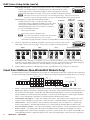
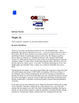
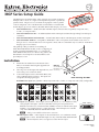
Front Panel Buttons (Non-WindoWall Models Only)
The MGP 464 (shown below) and MGP 462xi front panels (non-WindoWall models only) contain the following buttons
to control and configure the MGP. When you press a button, the LCD panel displays the settings that you can change.
VIRTUAL VIDEO INPUTS
RGB / HD / VIDEO INPUTS
FREEZE
1
2
3
4
5
8
11
14
17
6
9
12
15
18
7
2
10
13
16
19
WINDOW
SELECT
1
2
PRESET
RECALL
/SAVE
WINDOW/
IMAGE
SIZE
BRIGHT/
CONT
DETAIL
3
4
ENTER
WINDOW/
IMAGE
POSITION
COLOR/
TINT
WINDOW/
IMAGE
ZOOM
ADJUST
MENU
NEXT
CONFIG
•
Freeze — Freeze the input in the currently selected window. To unfreeze the input, press this button again.
•
Inputs 1, 2, 3, and 4 — Select fully configurable inputs 1 through 4. On the MGP 464/462xi DI, these buttons can
also select the four DVI inputs. On the MGP 464/462xi HD-SDI, input buttons 1 and 2 can select the HD-SDI
inputs and buttons 3 and 4 can select the DVI inputs. To mute (turn off) the input in a window, press its button
twice (or once, if the button is already lit). The button flashes while the input is muted.
•
Virtual Inputs (5 through 19) — Select virtual inputs 5 through 19. These inputs can be configured via control
software or SIS commands to accept S-video, composite video, or standard definition component video only.
•
Window Select — Select a window to freeze/unfreeze, mute/unmute, select an input for, or to adjust using
Picture Control buttons. The MGP 464 models have four of these buttons; the MGP 462xi models have two.
•
Preset Recall/Save and Enter — Save the current settings to memory (preset), or recall a stored preset (up to 128).
•
Picture controls — (Six buttons left of the LCD screen) Adjust window and image size, brightness, range of
dark and light values (contrast), detail (sharpness), position, color, tint, and zoom. Use the horizontal ([) and
vertical ({) Adjust knobs to adjust the settings shown on the left and right sides of the LCD screen, respectively.
MGP Series • Setup Guide
MGP 464 and MGP 464W Setup Guide (cont'd)
Executive Mode (Non-WindoWall Models Only)
To prevent accidental changes to settings, executive mode locks all panel controls except Freeze, input selection,
Preset Recall/Save, and the RS-232/422 and Ethernet ports.
To enable/disable executive mode, press the Window/Image Size and Window/Image Position buttons
simultaneously, and hold them down for 2 seconds.
Setting Up the MGP Using the Front Panel (Non-WindoWall)
After you have installed and connected the MGP, follow these steps to use the MGP front panel to configure and
adjust the unit to get it ready for use. If installing a WindoWall processor (MGP 464W series), refer to the WindoWall
Console help file or the WindoWall Console Quick Reference card for information on configuring via software.
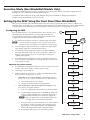
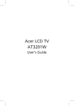
Configuring the MGP
Press the Menu button to access the Main menu, shown at right. Then,
repeatedly press the Menu button to cycle through the menus and
access the Input Configuration, Output Configuration, and Advanced
Configuration menus to perform steps 1 through 4.
1.
Extron
MGP 46X
VX.XX
2 sec.
Use the Input Configuration menu to configure inputs 1 through 4.
N
Multi-Graphic
Processor
The virtual inputs (5 through 19) can be configured only via the
Windows-based control software, SIS commands, or the Web pages.
2.
Use the Output Configuration menu to configure the output signal
type and the output rate for the desired resolution.
3.
From the Advanced Configuration menu, Test Pattern submenu,
Select the Alternating Pixels (Alt. Pixels) test pattern. Adjust your
display's active pixels, total pixels, and pixel phase settings for
optimal picture quality.
4.
Power
on
Menu
Auto
Image
Input
Configuration
6.
Select input 1 for all windows.
7.
Adjust all windows to full screen. On the non-WindoWall models,
this can be done using presets, as follows:
•
Output
Configuration
Window
Configuration
Background
Capture
b. Navigate to the desired preset and press Enter.
20 sec.
Menu
If the default presets have been replaced or changed, follow
these steps to set up the windows:
Comm. / IP
Configuration
Press one of the Window Select buttons to select a window.
20 sec.
Menu
b. Use the Window/Image Position and Window/Image Size
buttons with the Adjust knobs to set the window position
to 0,0 and set the window size to match the output rate.
Advanced
Configuration
N Make sure that the LCD window displays Window and 20 sec.
Menu
not Image while you are making the adjustment.
c. It may be necessary to mute windows to see other windows
below them. To mute a window, select it, then press the
input button for the selected window. The input button
blinks, indicating that the window has been muted.
20 sec.
Menu
If the MGP is set to factory defaults, select default window
preset 1, 31, 61, 91, or 121 to set the windows to full screen size:
a.
20 sec.
Menu
a. Press the Preset Recall/Save button.
•
20 sec.
Menu
Adjusting the picture controls
Use the Window Configuration menu to select a border color for each
window. This aids in window sizing and positioning.
20 sec.
Menu
From the Advanced Configuration menu, change the test pattern to
Crop, and adjust your display's positioning until all four sides of the
crop pattern are visible.
5.
Default
Cycle
2 sec.
Menu
Exit Menu
Press Next
20 sec.
Next
d. Repeat steps a through c for each remaining window.
MGP Series • Setup Guide
3
MGP Series Setup Guide (cont'd)
Adjusting the picture controls, continued
8.
Use the Input Configuration menu to make any desired advanced adjustments, including Horizontal and Vertical
Start, Pixel Phase, Total Pixels, Active Pixels, and Active Lines; or,
Perform Auto-Image™. Auto-Image is a quick way to size an input to fit the current window size. To perform
Auto-Image on an input,
a.
Press the button for the input that you want to auto size.
b. Press the Menu button once to select the Auto-Image menu.
c.
Press the Next button to display the Auto-Image screen.
d. Turn either Adjust knob to select a window to Auto-Image.
e.
9.
Press the Next button again to perform an Auto-Image in the selected window.
Size and position each window as desired for your application as follows:
a.
Press one of the Window Select buttons to select the window to adjust.
b. Press the Window/Image Position button once, and rotate the Adjust knobs to change the X and Y position.
c.
Press the Window/Image Size button once, and rotate the Adjust knobs to change the width and height of
the selected window.
d. If you want to adjust any contrast, brightness, color, tint, or detail settings, press the appropriate picture
control button and rotate the Adjust knobs to select the values.
e.
Repeat steps a through d for the remaining windows as needed.
10. Save your configuration as a window preset (see below).
11. Size and position windows as desired for each of your applications. Save each one to any of the remaining 127
window preset names for easy recall of window settings (see below).
Saving and Recalling Presets
After configuration, save the settings as a window preset, as follows:
1.
Press the Preset Recall/Save button and hold it for at least 2 seconds, until the LCD panel displays the message
"Window Preset / Save to #nnn".
2.
Rotate either Adjust knob to select the preset number/name to which you want to save this configuration.
3.
Press the Enter button.
To recall and apply a saved preset, press the Preset Recall/Save button and immediately release it. The LCD window
displays "Window Preset / Recall #nnn". Rotate either Adjust knob to select a preset number, then press Enter.
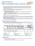
SIS (Simple Instruction Set) Commands
When setting up the MGP, you can issue SIS commands from your computer to the MGP via RS-232/422 or Ethernet,
as an alternative to the front panel controls. (Refer to your MGP user's manual for a complete list of SIS commands.)
Command
ASCII (Telnet)
(host to switcher)
Response
(host to processor
Additional description
Select an input
X50) * X50@ !
Out X50@ * In X50) ]
Select input X50) in window X50@.
Mute (blank) a window
Unmute a window
X50@ * 1B
X50@ * 0B
X50@ Blk1 ]
X50@ Blk0 ]
Blank (mute) window X50@.
Unmute window X50@.
Perform Auto-Image
55 * X50@ #
Img X50@ ]
Perform Auto-Image on input in window X50@.
Save window preset
Recall window preset
2 * X51# ,
2 * X51# .
Spr2 * X51# ]
Rpr2 * X51# ]
Save window settings as preset X51#.
Recall window preset X51#.
X50) = Input number (1-19)
X50@ = Window number (1-2 or 1-4); 0 = all windows (mute, input selection, and freeze only)
X51# = Window preset number: 1-128
Extron USA - West
Headquarters
+800.633.9876
Inside USA / Canada Only
+1.714.491.1500
+1.714.491.1517 FAX
Extron USA - East
Extron Europe
Extron Asia
Extron Japan
Extron China
Extron Middle East
+800.633.9876
+800.3987.6673
+800.7339.8766
+81.3.3511.7655
+81.3.3511.7656 FAX
+400.883.1568
+971.4.2991800
+971.4.2991880 FAX
+1.919.863.1794
+1.919.863.1797 FAX
+31.33.453.4040
+31.33.453.4050 FAX
+65.6383.4400
+65.6383.4664 FAX
Inside USA / Canada Only
Inside Europe Only
Inside Asia Only
© 2009 Extron Electronics. All rights reserved.
Inside China Only
+86.21.3760.1568
+86.21.3760.1566 FAX