1
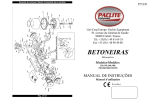
GENERATOR
MODEL :
GI Z O O R
INSTRUCTION MANUAL
I ISSUE EMD-GU0815 I
I 3229020046 I
FOREWORD
Thank you for purchasing this portable generator. This manual contains information and
operating procedures necessary for the effective, economical and safe operation of the
generator. For the proper operating procedures, read this manual thoroughly before
operating the generator.
For further details or questions, consult your nearest dealer.
0 Due to a constant effort to improve the product and because of a continuous program
of research and development, certain procedures, specifications and equipment are
subject to change without notice.
TABLE OF CONTENTS
1. SAFETY PRECAUTlONS
....................................................
1
2. COMPONENTlDENTlFlCATlON .............................................
3
3. CONTROLSAND INDICATORS ..............................................
5
4. BEFORE OPERATION (NECESSARY INSPECTIONS /CHECKS) . . . . . . . . . . . . . . . 7
................................
5. OPERATING PROCEDURES . . . . . .
9
.................................................
6. PERlODlC MAINTENANCE
.13
.....................................................
PREPARATION FOR STORAGE .............................................
TROUBLESHOOTlNG . . . . . . . . . . . . . . . . . . . . . . . . . . . . . . . . . . . . . . . . . . . . . . . . . . . . . .
7 . EASY MAINTENANCE
8.
9.
10. APPLICABLE WATTAGE OF THE GENERATOR
...........................
.........................................................
.................................
WIRING DIAGRAM . . . . . . . . . . . . .
.15
17
.18
..I9
11. SPEClFlCATlONS
.21
12.
.22
1. SAFETY PRECAUTIONS
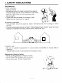
Fire prevention
0 When refueling :
- Stop the engine.
- Extreme care must be taken to prevent fire hazards.
Avoid smoking and the use of matches or open flame.
- Be sure to fill fuel tank up to the specified level.
Do not overfill.
- Spilled fuel must be wiped off thoroughly. After
spilled fuel has dried, start the engine.
8
('
v-
Location of generator :
- The generator should be placed at least 1 meter (3 ft) away from buildings or other
facilities.
- The surrounding area should be free of inflammables (trash, chips of wood, etc.) and
hazardous materials (lubricants, celluloid items, explosives, etc.).
0
0
0 While in use :
- Be sure to operate the generator on a level surface. Avoid tilting or moving while in
operation.
-The generator should not be covered or enclosed by a box.
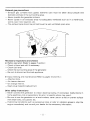
Prevention of electrical shock
- Never use the generator in the rain or snow.
- Never operate the generator with wet hands.
- Never spray water to clean the generator.
- 1 -
Exhaust gas precautions
-Exhaust gas contains toxic gases. Extreme care must be taken about people and
domestic animals in the surrounding area.
- Never operate the generator indoors.
- Never oprate in an enclosed area not adequately ventilated such as in a warehouse,
tunnel, well, hold, reservoir, etc.
- The exhaust pipe should be pointed toward a well-ventilated open area.
Necessary inspections and checks
0 Before operation (Refer to pages 7 and 8.):
- Check oil level and refill if necessary.
- Check fuel level.
-Check the surrounding area of the generator,
- Be sure to disconnect the load appliance.
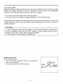
Easy checking and maintenance (Refer to pages 15 and 16.)
tools.
- Air cleaner element.
- Oil change interval.
- Spark plug inspectioniadjustment.
0
- Attached
Other safety instructions
- Never connect the generator to indoor electrical wiring. If connected, malfunctions in
home electrical units or generators, fire and / or electric shock may result.
- Be sure to use the generator on a level surface, never use on a soft or uneven surface
with small rocks, soil, gravel, etc.
- If abnormal conditions such as excessive noise or odor or vibration appears, stop the
engine immediately and consult your dealer for the necessary information,
- 2
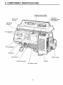
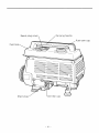
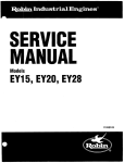
2. COMPONENT IDENTIFICATION
Engine control switch
(CHOKE-RUN-STOP)
Ground terminal
I
Air cleaner cover
- 3 -
Muffler
Fuel
-4-
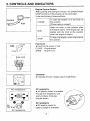
3. CONTROLS AND INDICATORS
2”:
OP
CHOKE
1
To start the engine, turn the knob to
this position.
(Choke valve is closed.)
RUN
Keep the knob in this position after
the engine starts. (The engine can be
started with the knob at this position
when the engine is warm.)
1
STOP
To stop the engine, return the knob to
this position.
Fuel Cock
0 Controls the supply of fuel.
CLOSE : Engine stops.
OPEN : Engine runs.
CLOSE
FUEL
OPEN
CHOKE
v
7
Fuel cock
\
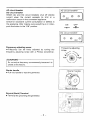
Voltmeter
0 Indicates the AC voltage output of generator
.
AC receptacle
0 AC electric power is available
through this receptacle. Use
a ground type, three-leg
plug as shown.
AC receptacles
I
\
I
0
7”:
0
8.3A
DC receptacle
0 DC electric power for
battery charge is available.
DC receptacle
-5-
AC circuit breaker
DC circuit breaker
0 Both AC and DC circuit breakers shut off electric
current when the current exceeds its limit or a
malfunction occurs in the connected appliance.
Check for excessive current consumption or defects in
the appliance. After making sure everything is in order,
push the button to the "ON" position.
m i c i r c u i t breaker
[
7
I
Frequency adjusting screw
0 Frequency can be finely adjusted by turning the
frequency adjusting screw with a Phillips screwdriver.
1
I
DC circuit breaker
Frequency adjusting
-~
Starter handle
0 Pull this handle to start the generator.
i
'
-I
~
Starter handle
\
I
Recoil starter
Ground (Earth) Terminal
0 Terminal for grounding the generator.
Ground termina
- 6 -
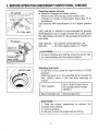
4. BEFORE OPERATION (NECESSARY INSPECTIONS / CHECKS)
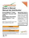
Checking engine oil level
0 Remove oil gauge and check oil level :
- If level is low, fill to the top of the oil filler neck.
-Change oil if badly contaminated. (See page 15 for
procedure.)
Use class SC (API classification) oil or a higher grade of
oil.
3
SAE 1OW-30 or 1OW-40 is recommended for general,
all-temperature use. If single viscosity oil is used, select
the appropriate viscosity for the average temperature in
your area.
Oil filler neck
SAE 1OW-30 - For general, all temperature use
- For cold weather below -1 5 "C(5"F).
SAE 5W
Oil level checking and refilling should be performed
on a level surface with the engine stopped.
I/ /
LEVELmark
I
I
Checking fuel level
- If fuel level is low, place the engine switch to "STOP"
position.
- Refill fuel tank up to the specified level indicated by
the "LEVEL" mark in the fuel filler openings as
shown.
Tank capacity
I Recommended fuel I
3.5 lit. (0.92 U.S.gal) (up to
the specified level marked
"LEVEL")
Non-lead gasoline
I
I
+CAUTION
1. Take the proper precautions to prevent fire
hazards when refilling.
2. Avoid overfilling.
3. Be sure to stop the engine before refilling.
- 7 -
Checking the area around the generator
- Area should be free of inflammables and hazardous materials.
- The generator is placed at least 1 meter (3 ft) away from buildings or other facilities.
- Generator is located in well-ventilated, open area.
- The exhaust pipe is pointed toward a well-ventilated open area.
- The generator is positioned away from any type of open flame or sparks.
- The generator is placed in a stable condition on a level surface, not on an inclined or
uneven surface.
- The generator is not enclosed or blocked by obstacles such as pieces of
wood, cardboard, etc.
0 Be sure to disconnect the appliance from the generator before starting. It is very
dangerous to start the engine with the appliance on since the appliance may start
suddenly.
Check to make sure that the switch of the appliance is turned off or its plug is disconnected from the receptacle.
- 8 -
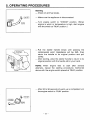
5. OPERATING PROCEDURES
Starting
- Check oil and fuel levels.
- Make sure the appliance is disconnected.
-Turn engine switch to "CHOKE" position. (When
engine is warm or temperature is high, start engine
with the switch at "RUN" position.)
-Pull
the starter handle slowly until passing the
compression point (resistance will be felt), then
return the handle to its original position and pull
swiftly.
-After starting, allow the starter handle to return to its
original position with the handle still in your hand.
NOTE : When engine fails to start after several
attempts, repeat the starting procedures mentioned
above with the engine switch placed at "RUN" position.
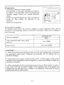
- After 20 to 30 seconds of warm-up is completed, turn
the engine switch to "RUN" position.
-9-
AC application
- Check the voltmeter for proper voltage.
The generator is thoroughly adjusted and tested in
the factory. If the generator does not produce the
specified voltage, consult your nearest Generator
dealer.
-Check the electrical appliance to see if its switch is
turned off, then connect the appliance to the
generator.
- Switch on the appliance.
e Applicable AC wattage :
The following table shows the maximum wattage of various appliances which can be
connected to the generator. Before connecting an appliance, make sure its wattage is
within the range.
Applicable limit
Electrical appliance
60Hz
Lamp, electrical heater, radio, stereo
sets, etc.
up to 1ooow
up to about 600W
Electric tools
CAUTION]
1, When connecting plural appliances make sure the total wattage does not exceed
the generator's rated output. Otherwise the generator will not operate due to
excessive wattage.
2. Some power tools require a large starting current. In these cases, it may not be
possible to use the generator. Refer to page 20, or consult your dealer to obtain the
necessary information.
3. When overloaded, the AC circuit breaker pops out to cut off the current. In such a
case, make sure that the applied wattage of the appliance has not exceeded the
wattage limit and that there are no defects in the appliance. Then push the circuit
breaker back into the "ON" position.
-
10
-
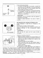
o Grounding the generator
-To ground the generator to the earth, connect the
grounding lug of the generator to the gounding spike
driven into the earth or to the conductor which has
been already grounded to the earth.
- If such grounding conductor or grounding electrode
is unavailable, connect the grounding lug of the
generator to the grounding terminal of the using
electric tool or appliance.
CAUTION
Generator must be grounded when the electrical
appliance is grounded.
Failure to ground generator may lead to electric
shock.
I
I
DC application (For charging 12V battery only)
0 DC receptacle is used only for charging a 12V
battery.
0 Connection of battery charging cables :
Using the attached DC plug, connect its positive and
negative terminals to the corresponding battery
terminals.
I
DC receptacle
I
0
Battery charging procedures :
- Make the proper connection as mentioned above, be
careful not to make a wrong connection. Be sure to
disconnect all cables connected from battery to any
other appliance.
- Remove all plugs from top of battery.
- Check electrolyte level and add distilled water if
necessary, to bring the electrolyte level to the level
marked "UPPER".
- Start engine to charge battery.
The charging
.time varies depending on the condition of
discharge. The specific gravity of a battery electrolyte indicates the state of charge in
each battery cell. While charging battery, check the specific gravity with a hydrometer,
using a thermometer to correct hydrometer reading for temperature. A corrected specific
gravity reading of 1.26 to 1.28 in all cells indicates a fully charged battery.
Example : In case of 12V-40Ah automobile battery, it takes 5 to 6 hours to bring a
completely discharged battery to a state of full-charge.
- 11 -
0 Charging safety :
Batteries produce explosive hydrogen gas. This gas is emitted from the vent hole of each
battery cap. Safety precautions must be observed to prevent ignition and subsequent
explosion of the hydrogen gas caused by open flame or sparks.
- No smoking and open flame near a charging battery.
- Be sure to perform the battery charging operation in a well-ventilated area.
Extreme care must be taken as electrolyte will burn eyes, skin and clothing. If injured, use
a large quality of water to clean the affected area immediately, then consult a doctor for
medical treatment.
i
CAUTION]
1. When charging a large capacity battery, DC output will exceed the limit and the
DC circuit breaker will pop out to the "OFF" position. In such a case, push DC circuit
breaker into the "ON" position after checking the battery.
2. Do not use DC and AC output simultaneously.
Stopping generator
Proceed as follows :
- Turn off electrical appliance switch and disconnect
cable from receptacle.
-Turn engine switch to "STOP" position
- 12 -
.-
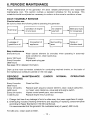
6. PERIODIC MAINTENANCE
Proper maintenance of the generator will allow reliable performance and reasonable
maintenance cost. This section outlines a standard schedule for this purpose. This
schedule should be adjusted as necessary to conform to the owner's conditions of use.
Fuel level
-E
Leakage of
gasoline or oil
Condition of engine
oil and level
-
-
Bolts and nuts
for looseness
Air cleaner
element
Surrounding
Connection of
appliance
-- area
-
Noise or
vibration level
Easy maintenance
Wash cleaner element (or everyday when operating in extremely
Every 50 hours
dusty conditions.), clean spark plug.
Every 100 hours
Change oil.
Adjust spark plug gap.
Every 6 months
(200 hours)
See page 15 for detailed information.
Draw up the most convenient schedule for conducting required checks, on the basis of
the maintenance schedule outlined on the next page.
PERIODIC
MAINTENANCE
CONDITIONS)
Every 6 months
(200 hours)
Every 12 months
(500 hours)
Every 24 months
(1,000 hours)
(UNDER
NORMAL
OPERATING
Clean fuel filter.
Replace spark plug and cleaner element, clean / adjust carburetor,
cyl. head, valve clearance, valve seat and engine switch.
Inspect control panel parts, rotor and stator.
Replace engine mount,overhaul.
1. Change fuel lines if any leakage is found or after every two years regardless of usage.
2. Overhauling includes checking dimensions and adjusting or replacing component parts
according to Repair Standards in the Service Manual.
It is recommended that the generator be overh,auled every 2 years(1,OOO hours).
For USA only : Clean spark arrester.
-
13 -
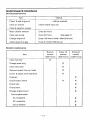
MAINTENANCE SCHEDULE
Do-it-yourself service
I
I
Item
I
Clean air cleaner
Clean & retighten screws
I
Interval
....refill as required
Check & add engine oil
Check before each use
I
I
Wash cleaner element
Every 50 hours
Clean spark plug
Every 50 hours
Change engine oil
Every 100 hours (initial : after 20 hours)
Adjust spark plug gap
Every 6 months (200 hours)
See page 15.
Periodic maintenance
Every 6
months
(200 hours)
Item
_____
Every 12
Every 24
months
months
(500 hours) (1,000 hours)
#
Clean fuel filter
Change spark plug
Clean carburetor
Remove carbon from cyl. head
Check & adjust valve clearance
Overhaul
#
Check engine switch
Check rotor
Check stator
Change engine mount
Control panel parts
AC receptacle
DC receptacle
Circuit breaker
- 14
-
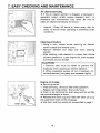
7. EASY CHECKING AND MAINTENANCE
Air cleaner servicing
0 If the air cleaner element is clogged, a decrease in
generator output, erratic engine operation and / or
excessive fuel consumption may result. Be sure to
clean air cleaner periodically as follows :
Interval : Every 50 hours or clean every day (or
every 10 hours) when operating in extremely dusty
conditions.
Q?o I
Cleaning procedure
-Using a coin, loosen screw securing air cleaner
cover in place and remove cover.
-Remove
element and clean with fresh cleaning
solvent.
-After cleaning, soak element in a clean fuel mixture
(3 parts gasoline to 1 part engine oil), then squeeze
out excess oil and reinstall.
1. Extreme care must be taken to prevent fire
especially when cleaning air cleaner element.
2. When squeezing excess oil out of element, do
not twist element, just grasp and squeeze it tightly.
Drain plug
Engine oil change
0 Servicing period :
- Initial servicing : 20 hours after initial operation.
- Regular servicing period : Every 100 hours.
0 Drain oil by removing the drain plug and the oil filler
cap while the engine is warm.
0 Reinstall the drain plug and refill with fresh oil up to
the upper level mark on the oil gauge.
0 Use fresh and high quality oil as specified in page 7.
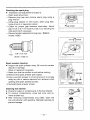
Checking the spark plug
0 Inspection and adjustment procedure :
- Open spark plug cover.
-Remove plug cap and remove spark plug using a
plug wrench.
-Using plug cleaner or wire brush, clean plug electrode of burnt or deposited carbon.
- Check for proper gap between electrodes. Adjust
gap to 0.6 to 0.7 mm (0.02 to 0.03 in) by bending the
side electrode if necessary.
- Recommended replacement plug type : BR6HS
(make : NGK).
AL
0.6-0.7
(0.02-0.03
~ i u cover
g
7
mm
in)
Spark arrester cleaning
0 Inspect the spark arrester every 50 hours for carbon
deposit or damage.
Clean or replace if necessary.
1. Make sure that the muffler is cool before working.
2. Remove the spark arrester and inspect.
3. Use a wooden scraper or small wire bursh to scrape
away any dirt or carbon deposits from exhaust outlet
opening and spark arrester screen.
4. Reinstall spark arrester screen.
Cleaning fuel strainer
0 Check for water or contaminants in the fuel strainer.
0 To remove contaminants, close fuel cock and remove strainer cup.
0 After removing contaminants and water, wash the
cup and strainer with gasoline, Reinstall securely to
prevent leakage.
-
16
-
II
I
Spark arrester
-
\
8. PREPARATION FOR STORAGE
- Remove fuel strainer cup, open fuel cock and completely drain fuel from tank.
-After
draining fuel, reinstall strainer cup and close the fuel cock.
-Start and run the generator without an appliance connected until the carburetor is
completely empty of fuel.
- Change old lubricating oil with fresh oil.
- Clean air cleaner element.
- Remove spark plug and pour 5-10 cc (1 fl.oz.) of lubricating oil through the plug hole.
Then pull starter handle several times and reinstall the spark plug.
- Check for loose bolts and nuts. Retighten if necessary.
- Clean generator throughly and spray completely with a preservative spray if available.
- Be sure to place engine switch at the "STOP" position.
- Pull starter handle until resistance is felt and leave it in that position.
- Storage indoors in a well-ventilated, low humidity area is recommended.
CAUTION]
Extreme care must be taken when draining fuel tank. Never use water to clean the
generator.
- 17
-
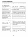
9.TROUBLESHOOTING
When engine fails to start or if the engine turns but there is no electricity at the
receptacles, perform the following checks.
When engine fails to start :
Place engine switch to "CHOKE" position to
start engine. ("RUN" position when starting a
warm engine.)
proper position.
If closed,open fuel cock.
Check fuel level.
If empty, refill fuel tank.
Check to make sure that the
generator is not connected to
an appliance.
-
If connected, turn off the power switch on the
connected appliance or disconnect power
cable.
~
Check spark plug for loose
plug cap.
Be sure to press spark plug cap securely.
Remove spark plug and clean electrode.
contamination.
I
L
I
When no electricity
I
is generated at receptacle :
Check AC or DC circuit
breaker if it is at the normal
operating "ON" position.
-
receptacle for loose
connections.
I
Secure connection, if necessary.
I
Check if engine starting was
attempted with the electrical
appliance connected.
After making sure that the total wattage of the
electrical appliance is within permissible limits
and there are no defects in the electrical
appliance, push AC or DC circuit breaker back
into "ON" position.
I
I
Turn off switch of the electrical appliance or
disconnect plug from receptacle and after the
generator is in a stable condition, make the
connection again.
* If engine still does not start, contact your dealer for further infomation.
-
18
-
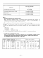
IO. APPLICABLE WATTAGE OF THE GENERATOR
Electric appliances normally come with a label indicating voltage, cycle and (input)
wattage, the electric power which the appliance consumes. However, when the generator
is used as the power source both power factor and starting current should be considered.
HEATING RESISTANCE (Power factor 1.O, No starting current)
Electrical loads such as incandescent lamps and hot plates require the same wattage as
indicated on the label.
Example : A 1 kW generator can power ten 1 OOW lamps.
ELECTRIC DISCHARGE TUBE (Power factor less than 1.O, Discharge
starting valtage is required.)
Loads such as fluorescent lamps and mercury lamps require 1.2 to 2 times the stated
wattage to start discharge.
Example : A 1kW generator can power three to seven 80W mercury lamps.
ELECTRIC MOTOR (Power factor less than 1.0, Starting current is
required.)
Electric motors require large starting wattage. Its power requirement depends on kind and
circumstance.
Electric tool (Driven by commutator motor, Shaft free in starting)
It speeds up quickly in starting, that is,it requires 1.2 to 3 times its wattage for starting.
Example : A 1 kW generator can power a 600W electric drill.
Loads such as submersible pumps and air compressors (Driven by
induction motor, Initially loaded by water or compressed air at
starting .)
Large power is required to start such load. Therefore, the generator has to supply 3 to 5
times the wattage for starting.
Example : A 1 kW generator is only able to drive a home use pump (up to about 250W).
- 19 -
Applicable wattage
Appliance
60Hz
I Incandescent lamp,hot plate
I Fluorescent lamp,mercury lamp
I Electric tool
I Pump,compressor
I
I
I
I
~
up to 1ooow
---1
I
I
I
up to about 600W
up to about 600W
up to about 250W
NOTE :
1. Appliances equipped with electric motors.
They need large starting current as mentioned above. However after starting, the
appliance requires only 1.2 to 2 times the wattage to continue running.Therefore, the
generator has reserve power for another appliance.
2. Some appliances will indicate output work instead of (input) wattage.
Example : 40W fluorescent lamp means 40W of the light beam is emitted from the lamp.
In such case, efficiency should be considered between the (input) wattage and output
work,
Efficiency
0.6 to 0 . 8 . . . . motor
0.7 to 0.8. . . . fluorescent lamp
The (input) wattage determined by the efficiency subjects to the same as above.
3. Voltage drop in long extension wires
When a long wire is used to connect an appliance with the generator, a certain amount
of voltage drop occurs in the wire which lessens effective voltage to the appliance.
The table below shows the values for a 1OOm wire
1 1
1
Sectional Allowable Gauge No./
Resistance
area
current wire element
Ohm11OOm
mm2
A
No.lmm
30l0.18
5OlO. 18
3.5
5.5
35
Voltage drop per 100 m
1A
3A
5A
2.477
2.5V
8V
12.5V
1.486
1.5V
5v
7.5v
1 .ov
3710.26
0.952
4510.32
0.517
7010.32
0.332
3v
5.0V
1.5v
2.5V
1v
--
-
20
-
2v
12V
15V
18V
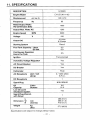
11. SPECIFICATIONS
1
DESCRIPTION
1
Engine Model
G1200R
I
Displacement
cc l c u i n
Frequency
HZ
EY15D (Wl -145)
60
Rated Output Watts
AC Continuous Dutv
r OutputMax. Watts AC
Engine Speed
RPM
Voltage
V
1000
I
1200
120
I
12 Volts
8.3Amps
I
Starting System
I
3600
Output DC
I
I
143 I 8.73
Recoil
Fuel Tank Capacity : Liters
US Gal.
Continuous Operation
Hours Per Tank
I
3.5
0.9
3.5
Ignition
Transistorized
Automatic Voltage Regulator
Yes
r A C Circuit Breaker
I
Yes
I
1
I
Yes
I
DCBreaker
Carburator
AC Receptacle
Float
Unit I Volt
(Amp)
2 I 125V (20A)
G.F.C.I.
D C Receptacle
I
1
I
Spark Plus
NGK BR6HS
Oil
Liters
Capacity
Ounces
Low Oil Level
Shutdown System
Spark Plug Wrench
with Driver
L
Dimension W
H
Weight
I
0.6
21
.o
Yes
1
486 (19.1)
288 (1 1.3)
410 (16.1)
mm
(inches)
kg
Ws)
27.5 (60.6)
Specifications are subject to change without notice.
-
21 -
I
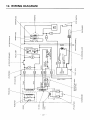
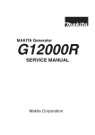
12. WIRING DIAGRAM
=’
0
0
z
t
z
P
IT
0
z
m
/!
(7
3
a
0
I
Y
I
I
I
2m
--El---
3
0
0
a
(0
=!
z\
0
w
LL
W
IT
m
z
n
z
W
IT
E
W
p/
v,
\$
W
m
IT
3
0
0
a
22
0
0
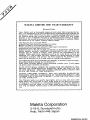
MAKITA LIMITED ONE YEAR WARRANTY
Warranty Policy
Every Makita tool is thoroughly ins ected and tested before leaving the factory. It is warranted t o be free of d e g c t s from workmanship and materials for
the period of ONE YEAR from t h e date of original purchase. Should any trouble develop during this one-year period, return t h e COMPLETE tool, freight
prepaid, t o one of Makita’s Factory or Authorized Service Centers. If inspection shows the trouble is caused by defective workmanship or material, Makita
will repair (or at our option, replace) without charge.
This Warranty does not apply where:
repairs have been made or attempted by others;
there is evidence of normal wear and tear;
0 The tool has been abused, misused or improperly maintained;
0 alterations have been made t o the tool.
Defects are due t o the use of parts, accessories or attachments which are not
Makita genuine products, specifically recommended for use with this tool.
Damage may be caused in transit. (This must be the responsibility of the
carrier.) Claims arise from regulations such as for noise levels, exhaust gas
emissions, etc. This product has been operated for racing purposes or other
competitive activities. This product has been employed for powering equipment that is operated on, in or near water or explosive atmospheres.
The following parts are expendable (not durable), so warranty does not apply:
Expendable parts including, but not limited to:
Spark plugs, packings, gaskets, rubber materials, washers, nuts, V-belt, engine
oil, grease, paper elements and brushes.
IN NO EVENT SHALL MAKITA BE LIABLE FOR ANY INDIRECT, INCIDENTAL OR CONSEQUENTIAL DAMAGES FROM THE SALE O R USE
O F THE PRODUCT. THIS DISCLAIMER APPLIES BOTH DURING AND
AFTER THE TERM O F THIS WARRANTY.
MAKITA DISCLAIMS LIABILITY FOR ANY IMPLIED WARRANTIES,
IUNCLUDING IMPLIED WARRANTIES O F “MERCHANTABILITY” AND
FITNESS FOR A SPECIFIC PURPOSE,” AFTER THE ONE-YEAR TERM
OF THIS WARRANTY.
This Warranty gives you specific legal rights, and you may also have other
rights which vary from state t o state. Some states do not allow the exclusion
of limitation of incidental or consequential damages, so the above limitation
or exclusion may not apply t o you. Some states do not allow limitation o n
how long an implied warranty lasts, so the above limitation may not apply t o
you.
0
Makita Corporation
3-18-8, Sumiyoshi-cho
Anjo, Aichi 446 Japan
PRINTED IN JAPAN