1
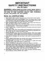
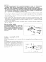
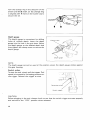
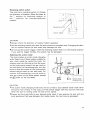
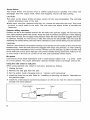
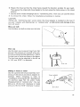
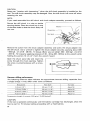
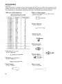
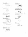
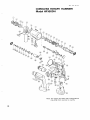
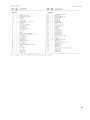
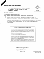
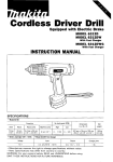
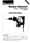
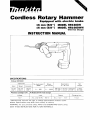
Cordless Rotary Hammer
Equipped with electric brake
16 mm (5/8”) MODEL HRIGODH
16 mm (518”) MODEL HRl6ODWH
With Fast Charger
INSTRUCTION MANUAL
SPECIFICAT10NS
Model HRIGODH
Capacities
1 3 mm
(112”)
2 0 mm
(314”)
No
1 6 mm
~
950
1
Blows
minute
Dimensions
(L x W x HI
weight
2 9 6 mm x 70 mm x 232 mm
(11-518” x 2-314” x 9-118”)
2.5 kg
(5.5 Ibs)
per
~~
3,600
(518”)
Battery Cartridge 1201
Model DC1201 Fast Charger
Voltage
12 v
load speed
Input
1
A.C. only 50
Hz
output
~
60 H r
1
D
C. 7 . 2 V
Charging time
12V
* Manufacturer reserves the right to change specifications without notice.
Note: Specifications may differ from country to country.
WARNING: For your personal safety, READ and UNDERSTAND before using
SAVE THESE INSTRUCTIONS FOR FUTURE REFERENCE.
1
1 hour
IMPORTANT
SAFETY INSTRUCTIONS
(For All Tools)
WARNING: WHEN USING ELECTRIC TOOLS, BASIC SAFETY
PRECAUTIONS SHOULD ALWAYS BE FOLLOWED TO REDUCE
THE RISK OF FIRE, ELECTRIC SHOCK, AND PERSONAL
INJURY, INCLUDING THE FOLLOWING:
READ ALL INSTRUCTIONS.
1. KEEP WORK AREA CLEAN. Cluttered areas and benches invite injuries.
2. CONSIDER WORK AREA ENVIRONMENT. Don't use power tools in damp
or wet locations. Keep work area well lit. Don't expose power tools to rain.
Don't use tool in presence of flammable liquids or gases.
3. KEEP CHILDREN AWAY. All visitors should be kept away from work area.
Don't let visitors contact tool or extension cord.
4.STORE IDLE TOOLS. When not in use, tools should be stored in dry, and high
or locked-up place - out of reach of children.
5. DON'T FORCE TOOL. It will do the job better and safer at the rate for which
it was intended.
6.USE RIGHT TOOL. Don't force small tool or attachment t o do the job of a
heavy-duty tool. Don't use tool for purpose not intended; for example, don't
use circular saw for cutting tree limbs or logs.
7 . DRESS PROPERLY. Don't wear loose clothing or jewelry. They can be caught
in moving parts. Rubber gloves and n o n s k i d footwear are recommended
when working outdoors. Wear protective hair covering t o contain long hair.
8. USE SAFETY GLASSES. Also use face or dust mask if cutting operation is
dusty.
9.DON'T ABUSE CORD. Never carry tool by cord or yank it t o disconnect from
receptacle. Keep cord from heat, oil, and sharp edges.
IO. SECURE WORK. Use clamps or a vise t o hold work. It's safer than using
your hand and it frees both hands t o operate tool.
1 1 . DON'T OVERREACH. Keep proper footing and balance at all times.
12. MAINTAIN TOOLS WITH CARE. Keep tools sharp and clean for better and
safer performance. Follow instructions for lubricating and changing accessories. Inspect tool cords periodically and if damaged, have repaired by authorized service facility. Inspect extension cords periodically and replace if
damaged. Keep handles dry, clean, and free from oil and grease.
13. DISCONNECT TOOLS. When not in use, before servicing, and when changing accessories, such as blades, bits, cutters.
2
14. REMOVE ADJUSTING KEYS AND WRENCHES. Form habit of checking t o
see that keys and adjusting wrenches are removed from tool before turning
it on.
15. AVOID UNINTENTIONAL STARTING. Don't carry tool with finger o n switch.
Be sure switch is OFF when plugging in.
16. EXTENSION CORDS. Make sure your extension cord is in good condition.
When using an extension cord, be sure t o use one heavy enough t o carry
the current your product will draw. An undersized cord will cause a drop
in line voltage resulting in loss of power and overheating. Table 1 shows the
correct size t o use depending on cord length and nameplate ampere rating.
If in doubt, use the next heavier gage. The smaller the gage number, the
heavier the cord.
TABLE 1
MINIMUM GAGE FOR CORD SETS
Total Length of Cord in Feet
___
~-
Ampere Rating
More
Not More
Than
Than
0
6
10
12
~
6
10
12
16
1
I
~
L
18
l8
;:
~
1
;:
12
A W G
~
1
16
14
14
I1
~
'4
12
12
Not Recommended
-
17. OUTDOOR USE EXTENSION CORDS. When tool is used outdoors, use only
extension cords intended for use outdoors and so marked.
1 8 . STAY ALERT. Watch what you are doing, use common sense. Don't operate
tool when you are tired.
19. CHECK DAMAGED PARTS. Before further use of the tool, a guard or other
part that is damaged should be carefully checked t o determine that it will
operate properly and perform its intended function. Check for alignment of
moving parts, binding of moving parts, breakage of parts, mounting, and any
other conditions that may affect its operation. A guard or other part that
is damaged should be properly repaired or replaced by an authorized service center unless otherwise indicated elsewhere in this instruction manual.
Have defective switches replaced by authorized service center. Don't use
tool if switch does not turn it on and off.
20. GUARD AGAINST ELECTRIC SHOCK. Prevent body contact with grounded
surfaces. For example; pipes, radiators, ranges, refrigerator enclosures.
21 . REPLACEMENT PARTS. When servicing, use only identical replacement parts.
22. POLARIZED PLUGS. To reduce the risk of electric shock, this equipment has
a polarized plug (one blade is wider than the other). This plug will fit in a
polarized outlet only one way. If the plug does not fit fully in the outlet,
reverse the plug. If it still does not fit, contact a qualified electrician t o install
the proper outlet. Do not change the plug in any way.
3
VOLTAGE WARNING: Before connecting the tool t o a power source (receptacle,
outlet, etc.) be sure the voltage supplied is the same as that specified on the
nameplate of the tool. A power source with voltage greater than that specified
for the tool can result in SERIOUS INJURY t o the user - as well as damage t o
the tool. If in doubt, DO NOT PLUG IN THE TOOL. Using a power source with
voltage less than the nameplate rating is harmful t o the motor.
4
IMPORTANT SAFETY INSTRUCTIONS
FOR CHARGER &
BATTERY CARTRIDGE
I.
SAVE THESE INSTRUCTIONS
- This manual
contains important safety and operating instructions for battery charger.
2.Before using battery charger, read all instructions and cautionary markings
on (1) battery charger, (2)battery, and (3) product using battery.
3.CAUTION - To reduce risk of injury, charge only MAKITA Battery Cartridge
1200,1201 & 1201A.Other types of batteries may burst causing personal
injury and damage.
4. Do not expose charger t o rain or snow.
5. Use of an attachment not recommended or sold by the battery charger
manufacturer may result in a risk of fire, electric shock, or injury t o persons.
6.To reduce risk of damage t o electric plug and cord, pull by plug rather than
cord when disconnecting charger.
7. Make sure cord is located so that it will not be stepped on, tripped over, or
otherwise subjected t o damage or stress.
8.A n extension cord should not be used unless absolutely necessary. Use of
improper extension cord could result in a risk of fire and electric shock. If
extension cord must be used, make sure:
a. That pins on plug of extension cord are the same number, size, and shape
as those of plug on charger;
b. That extension cord is properly wired and in good electrical condition; and
c. That wire size is at least as large as the one specified in the table below.
TABLE 1
RECOMMENDED MINIMUM AWG SIZE FOR
EXTENSION CORDS FOR BATTERY CHARGERS
Length of Cord (Feet)
AWG Size of Cord
25
18
50
18
100
18
150
16
9. Do not operate charger with damaged cord or plug - replace them immediately.
IO. Do not operate charger if it has received a sharp blow, been dropped, or otherwise damaged in any way; take it t o a qualified serviceman.
1 1 . Do not disassemble charger or battery cartridge; take it t o a qualified
serviceman when service or repair is required. Incorrect reassembly may
result in a risk of electric shock or fire.
12.To reduce risk of electric shock, unplug charger from outlet before attempting any maintenance or cleaning. Turning off controls will not reduce this risk.
5
ADDITIONAL SAFETY RULES
FOR CHARGER & BATTERY CARTRIDGE
1. Do not charge Battery Cartridge when temperature is BELOW 10°C (5OOF)
or ABOVE 4OoC (104OF).
2. Do not attempt t o use a step-up transformer, an engine generator or DC power
receptacle.
3.Do not allow anything t o cover or clog the charger vents.
4. Always cover the battery terminals with the battery cover when the battery
cartridge is not used.
5. A battery short can cause a large current flow, overheating, possible burns
and even a breakdown.
(1) Do not touch the terminals with any conductive material.
(2) Avoid storing battery cartridge in a container with other metal objects such
as nails, coins, etc.
(3)Do not expose battery cartridge t o water or rain.
6. Do not store the tool and Battery Cartridge in locations where the temperature may reach or exceed 5OoC (122OF).
7. Do not incinerate the Battery Cartridge even if it is severely damaged or is
completely worn out. The battery cartridge can explode in a fire.
6
ADDITIONAL SAFETY RULES
1. Wear a hard hat (safety helmet), safety glasses and/or face shield. It is also
highly recommended that you wear a dust mask, ear protectors and thickly
padded gloves.
2. Be sure the bit is secured in place before operation.
3. Under normal operation, the tool is designed t o produce vibration. The screws
can come loose easily, causing a breakdown or accident. Check tightness
of screws carefully before operation.
4. In cold weather or when the tool has not been used for a long time, let the
tool warm up for several minutes by operating it under no load. This will
loosen up the lubrication. Without proper warm-up, hammering operation
is difficult.
5. Always be sure you have a firm footing.
Be sure no one is below when using the tool in high locations.
6.
7.
8.
9.
Hold the tool firmly with both hands.
Keep hands away from moving parts.
Do not leave the tool running. Operate the tool only when hand-held.
Do not point the tool at any one in the area when operating. The bit could
fly out and injure someone seriously.
IO. When drilling or chipping into walls, floors or wherever "live" electrical wires
may be encountered, DO NOT TOUCH ANY METAL PARTS OF THE TOOL!
Hold the tool by the insulated grasping surfaces t o prevent electric shock
if you drill or chip into a "live" wire.
11. Do not touch the bit or parts close t o the bit immediately after operation;
they may be extremely hot and could burn your skin.
SAVE THESE INSTRUCTIONS.
Installing or removing the battery cartridge
Always switch off the tool before insertion or removal of the battery cartridge.
To remove the battery cartridge, pull out the
set plate on the tool and grasp both sides
of the cartridge while withdrawing it from
the tool.
To insert the battery cartridge, align the
tongue on the battery cartridge with the
groove in the housing and slip it into place.
Snap the set plate back into place. Be sure
to close the set plate fully before using the
tool to prevent the battery cartridge from
accidentally falling out of the tool.
Do not use force when inserting the battery cartridge. If the cartridge does not slide in
easily, it is not being inserted correctly.
Charging
Your new battery cartridge is not charged.
Battery cartridge
You will need to charge it before use. Use
the fast charger Model DC1201 to charge
the battery cartridge.
Plug the fast charger into the proper AIC
voltage source. The charging light will flash
in green color.
Insert the battery cartridge so that the plus
and minus terminals on the battery cartridge are on the same sides as their
respective markings on the fast charger.
Insert the cartridge fully into the port so that it rests on the charger port floor.
When the battery cartridge is inserted, the charging light color will change from green
to red and charging will begin. The charging light will remain lit steadily during chrging.
When charging is completed, the charging light color will change from red to green and
a tone will sound steadily for about 5 seconds.
After charging, unplug the charger from the power source. Refer to the table below for
the charging time.
Fast charger
DC1201
Battery cartridge
8
1200
Approx. 45 min.
1201 or 1201A
Approx. 60 min.
Side grip (auxiliary handle)
The side grip swings around to either side,
allowing easy handling of the tool in any
position. Loosen the side grip by turning it
counterclockwise, swing it to the desired
position and then tighten it by turning
clockwise.
‘lamp
Screw
Side grip
Installing or removing the drill bit
CAUTION:
Always be sure that the tool is switched off and unplugged before installing or removing
the bit.
To install the bit, turn the change ring in the
direction of the arrow until the I mark on the
change ring is aligned with the I mark on
the rubbedr cap. Align the key groove on the
bit shank with the 1 mark on the rubber cap
and insert the bit.
Key groove
I
\
Rubber cap
?
Change ring
Turn the change ring in the direction of the
arrow until the 1 mark on the change ring
is aligned with 0 mark on the rubber cap to
secure the bit.
Depth gauge
The depth gauge is convenient for drilling
holes of uniform depth. Insert the depth
gauge into the hole in the grip base. Adjust
the depth gauge to the desired depth and
then tighten the clamp screw to secure the
depth gauge.
Depth gauge
NOTE:
The depth gauge cannot be used at the position where the depth gauge strikes against
the gear housing.
Switch action
To start the tool, simply pull the trigger. Tool
speed is increased by increasing pressure on
the trigger. Release the trigger to stop.
CAUTION:
Before plugging in the tool, always check t o see that the switch trigger actuates properly
and returns to the "OFF" position when released.
Reversing switch action
This tool has a reversing switch to change
the direction of rotation. Move the lever to
the ' position for clockwise rotation or
t h e * position for c o u n t e r c l o c k w i s e
rotation
I
Switch trigger
u
~
CAUTION:
Always check the direction of rotation before operation.
Use the reversing switch only after the tool comes to a complete stop. Changing the direction of rotation before the tool stops may damage the tool.
Do not pull the switch trigger when the reversing switch lever is in the neutral position.
If you pull the trigger forcibly, the switch may be damaged.
Selecting the action mode
This tool employs an action mode changing
knob. Select one of three modes suitable for
your work needs by using this knob. For
rotation only, turn the knob so that the arrow
on the knob points toward the
mark on
the tool body. For hammering only, turn the
knob so that the arrow on the knob points
toward the
mark on the tool body. For
rotation with hammering, turn the knob so
that the arrow on the knob points toward
the
mark on the tool body.
+
/
\ 'Action mode
changing knob
CAUTION:
The action mode changing knob may not be turned to your desired mode mark when
the tool is not running. In this case, pull the switch trigger half-way and turn the knob
while the tool is running under no load at low speed.
Always set the knob fully to your desired mode mark. If you operate the tool w i t h the
knob positioned half-way between the mode marks, the tool may be damaged.
I1
Torque limiter
The torque limiter will actuate when a certain torque level is reached. The motor will
disengage from the output shaft. When this happens, the bit will stop turning.
CAUTIO N:
As soon as the torque limiter actuates, switch off the tool immediately. This will help
prevent premature wear of the tool.
Hole saws, core bits, diamond core bits, etc. cannot be used w i t h this tool. They tend
to pinch or catch easily in the hole. This will cause the torque limiter t o actuate too
frequently.
Hammer drilling operation
Position the bit at the desired location for the hole, then pull the trigger. Do not force the
tool. Light pressure gives best results. Keep the tool in position and prevent it from slipping
away from the hole. Do not apply more pressure when the hole becomes clogged with chips
or particles. Instead, run the tool at an idle, then remove the bit partially from the hole. By
repeating this several times, the hole will be cleaned out and normal drilling may be resumed.
CAUTIO N:
There is a tremendous and sudden twisting force exerted on the tool/bit at the time of hole
breakthrough, when the hole becomes clogged w i t h chips and particles, or when striking
reinforcing rods embedded in the concrete. Always use the side grip (auxiliary handle) and
firmly hold the tool by both side grip and switch handle during operations. Failure to do
so may result in the loss of control of the tool and potentially severe injury.
Bit grease
Coat the bit shank head beforehand w i t h a small amount (about 0.5 - 1 g; 0.02 - 0.04
oz.) of bit grease. This chuck lubrication assures smooth action and longer service life.
Using the cold chisel or bull point
When using optional cold chisel or bull point, proceed as follows.
1.
2.
3.
4.
Unplug the tool.
Remove the side grip from the tool.
Set the action mode changing knob to "rotation w i t h hammering".
Install the chisel on the tool. Refer to "installing or removing the drill bit" described on
the previous page.
5. Install the chisel adapter (optional accessory) on the tool so that the chisel is inserted
through the chisel adapter.
I
I
12
1
Chisel adapter
\
Chisel
Clamp screw
I
I
6. Rotate the chisel so that the chisel faces toward the direction suitable for your work.
Then secure the chisel and chisel dapter to the tool using the clamp screw on the chisel
adapter.
7. Set the action mode changing knob to "hammering only". Now you can use the chisel.
8. To remove the chisel, follow the installation procedures in reverse.
CAUTIO N:
Always use "hammering only" action when the chisel adapter is installed on the tool. If
you use "rotation with hammering" or "rotation only", a malfunction and damage to the
tool will result.
Blow-out bulb
Use the blow-out bulb t o clean out the hole.
Dust cup
Use the dust cup to prevent dust from falling over the tool and on yourself when performing overhead drilling operations. Attach
the dust cup to the bit as shown in the figure.
The dust cup can be attached to the bit up
to 14.5 m m (9/16") in diameter.
Drilling in wood or metal
Use the optional drill chuck assembly (consisting of drill chuck and chuck adapter assembly). When installing it, refer t o
"installing or removing drill bit" described on
the previous page. Set the action mode
changing knob to "rotation only". You can
drill up to 13 m m (1/2") diameter in metal
and up to 18 m m (11/16") diameter in wood.
Chuck adapter
a
I
Drill chuck
13
CAUTIO N:
Never use "rotation with hammering" when the drill chuck assembly is installed on the
tool. The drill chuck assembly may be damaged. Also, the drill chuck will come off when
reversing the tool.
NOTE:
If you need assembled the drill chuck and chuck adapter assembly, proceed as follows.
Secure the drill chuck in a vise or similar
securing devise. Place the chuck key in one
of the three holes so that the chuck body will
not turn.
Chuck key
6
-,wre
Remove the screw from the chuck adapter assembly and screw the chuck adapter into
the drill chuck. Use a wrench t o tighten the chuck adapter securely, applying about 300
- 400 kgf . c m (21.6 - 28.9 Ib . f t ) torque. [Note: you can obtain 300 - 400 kgf . c m (21.6
- 28.9 Ib . f t ) torque by applying pressure of 30 - 40 kg ( 6 6 - 88 Ibs) to the wrench while
holding the portion 10 c m (4") form the wrench head.]
Open the chuck jaws fully and insert the
screw through the chuck opening. Tighten
the screw counterclockwise w i t h a screwdriver.
"$-
I
Screw
Hammer drilling performance
The following reference table indicates the approximate hammer drilling capacities from
a single charge. It may differ under some conditions.
Bit diameter
I
6.5 mm (114")
8.5 mm (21164")
10.5 mm (13132")
14.5 mm ( 9 / 1 6 " )
Hole deDth
I
3 0 mm ( 1-1/8")
I
I
4 0 mm ( 1-5/8")
4 0 mm (1-5/8")
No. holes
About 50
3 0 mm (1-1/8")
About 4 0
I
I
About 20
About 1 3
Compressive strength of concrete: 2 4 0 kg/cm2 (3,400 Ibs/inch21
CAUTION:
If the tool is operated continuously until the battery cartridge has discharged, allow the
tool to rest for 15 minutes before proceeding with a fresh battery.
14
MAINTENANCE
CAUTION:
Always be sure that the tool is switched off and the battery cartridge is removed before
attempting t o perform inspection or maintenance.
To maintain product SAFETY and RELIABILITY, repairs, maintenance or adjustment should
be performed by Makita Authorized or Factory Service Centers, always using Makita replacement parts.
ACCESSORIES
CAUTION:
These accessories or attachments are recommended for use with your Makita tool specified in this
manual. The use of any other accessories or attachments might present a risk of injury to persons.
The accessories or attachments should be used only in the proper and intended manner.
SDS plus Carbide-tipped bits
SDS to A-Taper adapter
Allows use of A-Taper bits w i t h SDS hammers
Part No. 7521 18-A
I
Part No.
71 1140-A
71 1141-A
71 1142-A
71 1 143-A
71 1144-A
71 1145-A
71 1 146-A
71 1 147-A
71 1 148-A
71 1 149-A
71 11 50-A
711151-A
71 11 52-A
71 11 53-A
71 11 55-A
71 11 56-A
71 11 57-A
71 11 58-A
71 11 59-A
711160-A
71 11 61-A
711162-A
711163-A
711164-A
711165-A
711166-A
71 1167-A
71 1168-A
711169-A
711170-A
71 11 71-A
711172-A
I
711174-A
Diameter
Overall length
5/32”
5/32”
311 6”
1/16”
3/16”
311 6”
3/16”
114’’
114”
114”
114”
114”
511 6“
5/16”
3/8”
3/8”
3/8”
7/16”
711 6“
711 6“
112”
112”
1/2”
1/2”
911 6”
9/16“
911 6”
5/8”
5/8“
5/8”
5/8”
11/16’’
12,.
6”
12”
24”
6”
12”
18”
3/4”
8”
12”
18”
4“
6”
6..
8”
A”
12”
14”
4”
6”
8”
Cotter (Drift key)
Part No. 765010-1
10”
14’’
6”
6”
12“
18”
24“
4
f
*Chuck key
SI3
Part No. 76341 1-7
6”
12”
18”
8”
12”
18“
24”
8”
T
Drill chuck S I 3
Part No. 763047-2
8”
71 11 77-A
71 11 78-A
12”
18”
7/8”
718”
1
Cold chisel (For gouging)
Part No. 798379-8
I
7
-
Chuck adapter
Bull point (For demolishing)
Part No. 798380-3
Chisel adapter
Blow-out bulb
Part No. 122460-7
Part No. 765009-6
16
1-
J
Part No. 122331-8
Bit grease 100 g; 3.5 oz
Fast charger
Part No 181 573-3
Model DC1201
Part
Dust cup
Part No. 4 2 1 3 4 2 - 3
No. 113126-0
Battery cartridge 1200
Part No. 192271-4
High capacity battery 1201
Part No. 192296-8
Dust extractor attachment
Part No. 192176-8
*Power display battery (High cap.) 1201A
Part No. 192407-5
Plastic carrying case
Battery cover
Part No. 824445-6
Part No. 414938-7
Stopper pole
Grip
Part No. 321 144-6
Part No. 273634-4
Safety goggle
Grey lens:
Part No. 191684-A
Clean lens: Part No. 191685-A
17
Sep -08-'94
US
CORDLESS ROTARY HAMMER
Model HRIGODH
Note: The switch and other part configurations
may differ from country to country.
18
Sep -08-'94
MODEL HHlGODH
'A,'$"
IFOMEDDESCRIPTION
D:$
MACHINF
US
DESCRIPTION
M h E
~~
comprezs,on S p m g 6
Push Cane
Pan Head Screw M 4
Screw 6 x 4 0
37
38
39
40
41
42
43
44
45
46
41
48
11
1 5 8 37
431
49
50
51
52
I
j
,
~
~
~
53
~
1
1
0 Ring 10
0 Ring 10
Impact Boll
1
1
1
Rubber Ring 1 7
1
Flal Washer 13
1
Ring Sprinq
Idler
5
23
1
SLrikrr
1
1
1
0 Ring 16
Pi51011 Cylinder
Flat Washer 12
Flat Washer 1 2
DC Motor 1 2 V
1
Radidttng P l a f ~
1
Pan Head S r i r w M J x l 0
Switch
Rubbrr Pin 4
1
1
1
1
l a p p i n g Screw 4 x 1 8
Rubber Pin ,$
High Capacity Battery 1201
Battery HOldrT
set Plate
60
61
62
63
61
7:'
,
1
1
~
Switch l c v o r
1
Dust Cover
1
Motor Hocib8ng Si4 W l h I t e m 251
Rubber Pic 4
Rubber Pin 4
Mdkitd LahPl
~
1
OR~nqli
__
19
The only way to dispose of a Makita battery is
to recycle it. The law prohibits any other
method of disposal.
i
Ni-Cd
To recycle the battery:
1. Remove the battery from the tool
2. a). Take the battery to your nearest Makita Factory Service Center
or
b). Take the battery to your nearest Makita Authorized Service Center or
Distributor that has been designated as a Makita battery recycling location.
Call your nearest Makita Service Center or Distributor to determine the location
that provides Makita battery recycling. See your local Yellow Pages under
"Tools-Electric'
4
i
1
t
i
MAKITA LIMITED ONE YEAR WARRANTY
Warranty Policy
I very M a k m tool IT thoroughiy inspected and trsfad before leaving t h e factory I f R warranted to
be free of dcfccts from workmanrhlp and matcnak for t h e penud ul'ONt, YI AR from the date of
original purchase. Should any trouble dcvrlop during lhi\ one~ycilrperiod. return tlic COMPLI..TL
tool freight prepaid. to one uf Makifa'a bactury or Authorized Service Centcrr. If inspection qhowr
t h e ;rouble IS caused by defective workmimehip o r malmal. 4lakita w i l l repair (or at our option.
rrplrce) without charge
Thn Warranty dur\ not apply w'hcre'
repairs have h e m made or attempted by U I I I E ~ F .
repair? arc required becauw of normal wear and tear
The t ~ m 1hay hccn abwed. miruied or improperly matntamcd,
dltciiltions have been made to the to01
.
IN NO 1 VI.NT SHALL MAKITA BI: LIABLt FOR ANY lNDlK1 CT, INCIDkNTAL OR CONS l Q U l NTlAL DAMAG1.S IKOM THL SALP OR USl. 01. THL I'ROUUCT THIS DlSCLA1Mk.R
API'Ll1.S BOTH DIIKINC; A N D A I . T k R T H F TLRM 01 THIS WARRANTY.
/
1
MAKITA DISCLAIMS LIABILITY IOR ANY IMPLIkD WARRANTITS, INCLCDING IMPLlkO
WARRANTIFS 0 1 MF.RCHANTABILITY" AND " I - I T N I S IOR A SPI CII-IC PURPOSI.,"
A I , I ' I R THL.ONF.-YI A R T I R M O I TlllSWARRANTY.
rhia Wdrranty give, you \pecikic lcgal riyht% and you m a y d l w havc vthcr riglitb which vary from
\talc. Somc FIPICS do not allow the cxdu~ionor limitation of incidental or consequential
dmirpes, w the above Imitation or enclusion may not apply to you. Soma \ t d f w do not d l o w
limitation on how long .it1 implied warranty l m t s , TU t h e above limitation may not apply tu you
;vdtc 10
Makita Corporation
3-11-8, Sumiyoshi-cho,
Anjo, Aichi 446 Japan
883900 - 069
PRINTED IN JAPAN
1994 - 12 - N