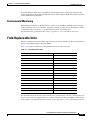
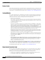
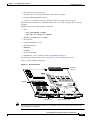
1
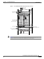
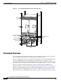
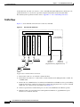
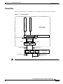
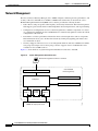
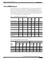
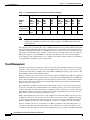
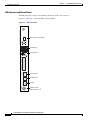
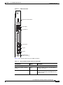
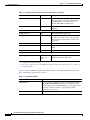
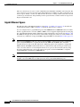
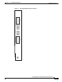
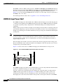
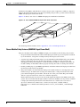
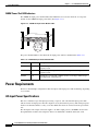
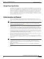
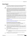
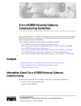
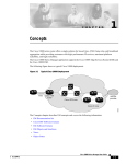
C H A P T E R
1
Cisco AS5850 Product Overview
The Cisco AS5850 is a high-density, ISDN and modem WAN aggregation system that provides both
digital and analog call termination. It is intended to be used in service provider dial point-of-presence
(POP) or centralized enterprise dial environments.
The gateway components include hybrid trunk and port-handling cards (both functions are handled by
different components in the same slot), dedicated port-handling cards, dedicated trunk cards, route
switch controllers, power entry modules, and a blower unit to cool the chassis. An optional 2400W AC
power shelf is also available. The gateway is designed with environmental monitoring and reporting
functions to help maintain normal system operation and resolve adverse environmental conditions prior
to loss of operation. If conditions reach critical thresholds, the system shuts down to avoid equipment
damage from excessive heat or electrical current.
Downloadable software and microcode allow you to load new software images into Flash memory
remotely, without having to physically access the universal gateway, for fast and reliable upgrades.
This chapter provides physical and functional overviews to familiarize you with your new
Cisco AS5850. The chapter also contains physical descriptions of system hardware and major
components and functional descriptions of component features.
Note
Descriptions and examples of software commands appear in this document only when they are
necessary for installing the system hardware. For software configuration information, refer to the
Cisco AS5850 Universal Gateway Commissioning Guidelines that shipped with your system, or the
Cisco AS5850 Universal Gateway Operation, Administration, Maintenance, and Provisioning
Guide. These documents are available on Cisco.com (http://www.cisco.com), by selecting:
Products and Services > Universal Gateways > Cisco AS5800 Universal Gateways
This chapter contains the following sections:
•
If You Already Have a Cisco AS5800, page 1-2
•
System Components, page 1-2
•
Functional Overview, page 1-4
•
Cisco AS5850 Chassis, page 1-9
•
Field-Replaceable Units, page 1-13
•
Split Backplane, page 1-11
•
Power Requirements, page 1-28
•
Online Insertion and Removal, page 1-29
Cisco AS5850 Universal Gateway Hardware Installation Guide
78-10573-06 0A
1-1
Chapter 1
Cisco AS5850 Product Overview
If You Already Have a Cisco AS5800
If You Already Have a Cisco AS5800
If you already have a Cisco AS5800, the Cisco AS5850 should be easy to adjust to. The following major
differences should be noted:
•
The cooling module is 1 RU shorter.
•
The Dial Shelf Controller (DSC) and Cisco 7206 router shelf were replaced with a route switch
controller (RSC) card, which goes in slots 6 and 7, not 12 and 13 (as with the DSC).
•
There is a new 2400-watt power shelf. This power module can use three 120V 15A connections or
three 240V 10A connections, depending on what is available at your site.
•
Because the chassis is shorter, and a separate router shelf (or two) are no longer needed, three
Cisco AS5850 gateways can fit in a standard rack, when DC-powered.
•
The separate power entry module (PEM) and power filter have been integrated into a single unit
(PEMF).
•
Trunk cards can be used in any feature card slot.
•
All modems are universal ports and support voice, data, or fax connections. For details about
universal ports, refer to the Cisco AS5850 Universal Gateway Card Guide, and the Cisco AS5850
Operations, Administration, Maintenance, and Provisioning Guide (available online at the
following URL:
http://www.cisco.com/univercd/cc/td/doc/product/access/acs_serv/as5850/sw_conf/5850oamp/
index.htm.)
•
Command syntax has shifted slightly. Because you no longer need to distinguish the Cisco 5814 dial
shelf from the Cisco 7206 router shelf, commands using the shelf/slot/port syntax are shortened to
slot/port. The shelf abstraction is no longer needed.
System Components
The following sections in this chapter describe the core system components:
•
Cisco AS5850 Chassis, page 1-9
•
Field-Replaceable Units
– For information about the feature cards used in the Cisco AS5850, refer to the Cisco AS5850
Universal Gateway Card Guide that shipped with your system. For information about other
FRUs, review the rest of this chapter, or for detailed specification tables, refer to Appendix A,
“Cisco AS5850 Specifications”, page 1-14
– Route Switch Controller Card, page 1-14
– DC-Input Power Entry Module, page 1-23
•
Power Requirements, page 1-28
The Cisco AS5850 is designed to be rack-mounted. A rack-mount kit is included with each
Cisco AS5850. Each rack-mount kit provides the hardware needed to mount the chassis in a standard,
19-inch equipment rack or standard telco rack. If you plan to use a 23-inch equipment rack, you must
provide your own brackets or shelves to accommodate the Cisco AS5850 and optional AC power shelf.
For clearance requirements and rack-mount installation considerations, refer to the section
“Site Requirements” in Chapter 2, “Preparing for Installation.”
Figure 1-1 shows a front view of a Cisco AS5850 with the optional 2400W power shelf, and Figure 1-2
shows a rear view.
Cisco AS5850 Universal Gateway Hardware Installation Guide
1-2
78-10573-06 0A
Chapter 1
Cisco AS5850 Product Overview
System Components
Figure 1-1
Cisco AS5850 with 2400W AC-Input Power Shelf—Front View
Power LED
Fault LEDs
Cooling module
Power
Fault
Bank 1 Bank 2 Bank 3
Captive screws
LOOP
LOOP
LOOP
RCVR
LOOP
RCVR
RCVR
XMTR
LOS
XMTR
LOS
T3 ENABLE/DISABLE
RCVR
XMTR
LOS
XMTR
LOS
T3 ENABLE/DISABLE
T3 ENABLE/DISABLE
RX
RX
RA
T3 ENABLE/DISABLE
RA
RA
LA
LA
MA
SERIAL
SERIAL
ACT
TX
TX
LA
MA
RX
RX
RA
TX
TX
LA
MA
MA
SERIAL
SERIAL
ACT
SERIAL
SERIAL
ACT
FCPU
SERIAL
SERIAL
ACT
FCPU
FCPU
14-slot card cage
(Line, port, and
RSC cards installed)
CPU/POWER
CPU/POWER
CPU/POWER
CPU/POWER
CPU/POWER
CALLS/MAINT
CALLS/MAINT
CALLS/MAINT
CPU/POWER
CPU/POWER
CALLS/MAINT
CALLS/MAINT
CALLS/MAINT
324 UNIVERSAL PORTS
324 UNIVERSAL PORTS
CALLS/MAINT
MIN
MIN
T
HIS
HIS
T
MIN
CHANNELIZED T3 +
216 UNIVERSAL PORTS
US
MB
R
PW
US
MB
R
PW
CHANNELIZED T3 +
216 UNIVERSAL PORTS
T
HIS
T
HIS
PORT STATUS
MIN
PORT STATUS
324 UNIVERSAL PORTS
324 UNIVERSAL PORTS
324 UNIVERSAL PORTS
CHANNELIZED T3 +
216 UNIVERSAL PORTS
CHANNELIZED T3 +
216 UNIVERSAL PORTS
PORT STATUS
CPU/POWER
324 UNIVERSAL PORTS
CALLS/MAINT
PORT STATUS
CPU/POWER
US
MB
R
PW
CALLS/MAINT
US
MB
R
PW
CALLS/MAINT
FCPU
CPU/POWER
PORT STATUS
PORT STATUS
PORT STATUS
PORT STATUS
PORT STATUS
PORT STATUS
Cool air intake
Route switch
controller (RSC) cards
Chassis installation
support bracket
DC OK AC OK FAULT
DC OK AC OK FAULT
56025
DC OK AC OK FAULT
2400W AC-input power shelf (optional)
Note
Figure 1-1 shows a system with two RSCs and a split backplane, and both sides supporting T3
connections. This is shown to illustrate full configurations on a split backplane.
Cisco AS5850 Universal Gateway Hardware Installation Guide
78-10573-06 0A
1-3
Chapter 1
Cisco AS5850 Product Overview
Functional Overview
Figure 1-2
Cisco AS5850 with AC-Input Power Shelf—Rear View
Warm air
exhaust
POWER
POWER
MISWIRE
MISWIRE
PEM
C
O N N
M C O
+
C
O N N
M C O
+
AC power supply
monitor cables
DC interconnect
cables
Ground cable
35395
2400W AC-input
power shelf
AC connection
cables
Functional Overview
The Cisco AS5850 supports high-density dial aggregation and integrates with the Cisco AS5350 and
Cisco AS5400 universal gateways for scaling your service provider network.
The Cisco AS5850 universal gateway also supports high availability of service through online insertion
and removal (OIR) capabilities and redundant power modules that are hot swappable. All active
components within the chassis support OIR, which allows components to be removed or replaced while
the system is powered on. Feature cards can be busied-out through the software to avoid loss of calls.
The Cisco AS5850 is compatible with the Cisco Universal Gateway Manager (UGM) network
management software. For more on Cisco UGM, see the “Network Management” section on page 1-8.
The Cisco AS5850 supports Channelized T1, E1,T3 PRI, and STM1 ingress interfaces that terminate
ISDN and modem calls at DS0 granularity. Digital calls are terminated onboard the trunk card, and
analog calls are sent to port handling resources on the same card or on other feature cards. As a result,
Cisco AS5850 Universal Gateway Hardware Installation Guide
1-4
78-10573-06 0A
Chapter 1
Cisco AS5850 Product Overview
Functional Overview
any DS0 can be mapped to any HDLC controller or universal port. You can install multiple ingress
interface cards of like types and configure the Cisco AS5850 for card or port level redundancy,
depending on your needs.
Trunk and port handling cards are tied together using several time-division multiplexing (TDM) buses
on the backplane. Each line card is also connected, through point-to-point packet buses, to a central
switch on the Route Switch Controller (RSC) cards. The RSC cards transmit and receive packetized data
across the IP network.
The Cisco AS5850 supports a split backplane configuration by using two RSC cards. In the classic-split
configuration, the system operates as two separate universal gateways with each RSC controlling its own
set of feature cards. In the handover-split mode, if one RSC fails, the other RSC takes control of the
failed RSC’s feature cards so their operation can continue. In the route processor redundancy (RPR+)
mode, one RSC acts as the active RSC that controls all the resources in the chassis. The other RSC is the
standby RSC and assumes control of the chassis if the active RSC fails. RPR+ enables a much faster
switchover than handover-split mode. For more information about the split backplane configuration,
refer to the “Split Backplane” section on page 1-11.
The RSC card also provides clock and power control to the feature cards. Each RSC card contains a block
of logic, referred to as the common logic, and system clocks. This block generates the backplane 4-MHz
and 8-KHz clocks used for interface timing and for the TDM bus data movement. The common logic can
use a variety of sources to generate the system timing, including a BITS input signal from the BNC
connector on the RSC front panel. The clock source can also be telco office timing units extracted from
the network ingress interfaces.
On the RSC card, only one common logic is active at any one time, which is identified by the CLK
(clock) LED on the RSC card front panel. The active common logic is user-selectable and is independent
from each RSC. This assures that if an RSC card needs replacing or if the slave RSC card becomes the
master, clocking remains stable. The selected common logic should not be changed during normal
operation unless related hardware failure is suspected or diagnosed.
You can install and upgrade software remotely, without affecting current system operation. You can also
upload and download configuration files remotely, without affecting current system operation. Remote
access is enabled by use of simple network management protocol (SNMP), by a Telnet session to a
console port on the router shelf, through the World Wide Web (WWW) interface, or through use of the
optional network management software.
The Cisco AS5850 can dynamically adjust any port to support any user configuration. Individual users
can be authenticated as they connect to the system by use of one or more authentication servers using
RADIUS and TACACS+ authentication protocols. Primary and backup authentication servers can define
user authentication parameters using the user domain and the number called. User profile information
can also be configured to include time of day, number of simultaneous sessions, and number of
B-channels used.
When a remote user connects to the universal gateway using a modem or an ISDN line, the user is
authenticated and establishes a session. Dynamic address assignment from an authentication server or
static address assignment connects the user and has virtually no impact on service provider routing
tables.
A remote LAN user can connect to the universal gateway using an ISDN line or asynchronous serial
connection, be authenticated, and establish a session. In addition to dynamic or static address
assignment, this connection requires the traditional Cisco IOS software support for different routing
protocols on different ports simultaneously, with virtually no impact on service provider routing tables.
Cisco AS5850 Universal Gateway Hardware Installation Guide
78-10573-06 0A
1-5
Chapter 1
Cisco AS5850 Product Overview
Functional Overview
A dial wholesale customer can connect to a Cisco AS5850, then tunnel PPP (Point-to-Point Protocol)
packet information to a retail service provider using dial Virtual Private Network (dial VPN).
For detailed system specification tables, refer to Appendix A, “Cisco AS5850 Specifications.”
Traffic Flow
Figure 1-3 shows inbound connection flow for the Cisco AS5850.
Figure 1-3
Inbound DS0 Traffic Flow
RSC
Cisco AS5850
universal gateway
GigE egress
universal port card
OC3/STM-1 trunk card
universal port card
T3
T1/E1 trunk card
Backplane
T1/E1
CAT5
T3
COAX
OC3/STM-1
SMF
Backbone
Backbone
Network 1
Network 0
(Gigabit Ethernet) (Gigabit Ethernet)
72964
2
1
Modem
Twisted pair
A typical user connection flows as follows:
1.
The user PC connects to an attached or internal modem.
2.
The modem call connects to a central office (circuit switched) and is multiplexed into a T1/E1, T3,
or STM1 trunk.
3.
The T1, E1,T3, or STM1 interface is terminated, and individual serial DS0s are sent to port-handling
hardware and software. Universal ports may be located in the same physical slot, as part of a hybrid
trunk card, or in a universal port card (UPC). (See Figure 1-3.)
4.
Universal ports interface with modem protocols and convert TDM data into Ethernet packets.
5.
Ethernet packets are routed and send out through the Fast Ethernet or gigabit Ethernet egress
interfaces to a backbone network.
Cisco AS5850 Universal Gateway Hardware Installation Guide
1-6
78-10573-06 0A
Chapter 1
Cisco AS5850 Product Overview
Functional Overview
Power Flow
Figure 1-4 shows how power is distributed to various universal gateway field-replaceable units.
universal port card
Power Distribution
trunk card
Figure 1-4
Cisco AS5850
universal gateway
Backplane
GigE egress
RSC
-48 VDC 50A
-48 VDC 50A
Cooling
module
-48 VDC
-48 VDC
PEMF 1
PEMF 2
-48 VDC 50A
-48 VDC 50A
120/240 VAC 15A
PS 2
PS 3
2400W AC-input
power shelf
(optional)
120/240 VAC 15A
120/240 VAC 15A
Note
72965
PS 1
VDC output of the 2400 W AC power shelf is set at -51 volts DC.
Cisco AS5850 Universal Gateway Hardware Installation Guide
78-10573-06 0A
1-7
Chapter 1
Cisco AS5850 Product Overview
Functional Overview
Network Management
The Cisco Universal Gateway Manager (Cisco UGM) configures and manages fault, performance, and
security of the Cisco AS5850. Cisco UGM is a UNIX-based solution that can be run from a Cisco
Element Management Framework (EMF) server, and also provides the following features:
•
Fault—Device and port-specific alarm frequency and severity information. The fault management
GUI supports point-and-click alarm acknowledgement and clearing functions, and trap forwarding.
•
Configuration—Configuration services for the managed devices and their components. As objects
are configured or modified, the Cisco UGM database is automatically updated to reflect the current
configuration of the network.
•
Performance—Collects performance information from each managed device and its components.
This information allows you to monitor the network by viewing and graphing performance data
associated with an object.
•
Security—Supports role-based access to its management functions. The user administrator defines
user groups and assigns users to these groups, and also supports control of administrative state
variables for Cisco UGM resources.
Figure 1-5 shows the flow of system management information for the Cisco AS5850.
Figure 1-5
System Management Information Flow
Network management software or terminal
GigE or FE ports
RSC
Cisco AS5850
universal gateway
trunk card
Backplane
universal port card
Cooling
module
PEMF 2
2400W AC-input power shelf
72966
PEMF 1
Cisco AS5850 Universal Gateway Hardware Installation Guide
1-8
78-10573-06 0A
Chapter 1
Cisco AS5850 Product Overview
Cisco AS5850 Chassis
Cisco AS5850 Chassis
The Cisco AS5850 contains 14 slots (numbered 0 through 13 on the backplane) and can support trunk
cards and universal port cards in slots 0 through 5 or 8 through 13. Slots 6 and 7 in the chassis are
dedicated slots for the RSCs. There are two versions of the RSC, RSC and ERSC. ERSC has a faster
CPU, more memory, and two Fast Ethernet ports. Metal guard pins on the backplane module prevent you
from installing any other type of card in these two slots. The modular chassis supports online insertion
and removal (OIR) and redundant power and includes environmental monitoring and feedback control.
Table 1-1 shows the possible trunk card configurations for RSC:
Table 1-1
Maximum Number of Trunk Cards for RSC
Total
DS0s
with
RSC
Total
Ports
with
RSC
Chassis Trunk Type
First RSC
Second RSC
Total
Trunk
Total
Cards Per 324-port
Chassis
UPC
24T1 only
2 24T1
2 24T1
4
8
2304
2592
T3 only
2 T3
2 T3
4
6
2688
2808
24T1/T3 combination
2 24T1
2 T3
4
7
2496
2700
24T1/T3 combination
1 24T1,
1 T3
1 24T1,
1 T3
4
8
2496
3024
24T1/T3 combination
1 24T1,
1 T3
2 T3
4
7
2592
2916
24T1/T3 combination
2 24T1
1 24T1,
1 T3
4
8
2400
2808
24E1 only
2 24E1
2 24E1
4
8
2880
2592
STM1 only
1STM1
1 STM1
2
10
4032
3240
24E1/STM1
combination
2 24E1
1 STM1
3
9
3456
2916
Table 1-2 shows the possible trunk card configurations for ERSC:
Table 1-2
Maximum Number of Trunk Cards For ERSC
Non-Split Chassis
Split Chassis
Chassis
Trunk
Type
Total
Trunk
Cards Per
Chassis
Total
DS0s
Total
324-port with
ERSC
UPC
Total
Ports
with
ERSC
Total
Trunk
Cards Per
Chassis
Total
DS0s
Total
324-port with
ERSC
UPC
Total
Ports
with
ERSC
24T1
5
7
2880
2268
2
4
1152
1296
T3
5
7
3360
3348
2
3
1344
1404
24E1
4
8
2880
2592
2
4
1440
1296
STM1
2
10
3780
3240
1
5
1890
1620
Cisco AS5850 Universal Gateway Hardware Installation Guide
78-10573-06 0A
1-9
Chapter 1
Cisco AS5850 Product Overview
Cisco AS5850 Chassis
Table 1-2
Maximum Number of Trunk Cards For ERSC (continued)
Non-Split Chassis
Split Chassis
Chassis
Trunk
Type
Total
Trunk
Cards Per
Chassis
Total
DS0s
Total
324-port with
ERSC
UPC
Total
Ports
with
ERSC
Total
Trunk
Cards Per
Chassis
Total
DS0s
Total
324-port with
ERSC
UPC
Total
Ports
with
ERSC
24T1/T3
combination
3 24T1
2 T3
7
3072
2700
1
1
1248
1512
24E1/STM1
1 STM1
2 24E1
7
3330
3240
—
—
—
—
Note
Mixing CT1 or CT3 and CE1 or STM1 in the same chassis is not supported. If this
configuration guideline is violated, an error message appears on the RSC and the disallowed
card is shut down.
The universal gateway uses CT1, CE1, CT3, or STM1 trunk interfaces that terminate ISDN and modem
calls and break out individual calls from the appropriate telco services. Digital calls are terminated on
the trunk card high-level data link control (HDLC) controllers, and analog calls are terminated on the
universal ports on the trunk card, if available, or universal ports on another feature card. As a result, any
DS0 can be mapped to an onboard HDLC controller or any universal port. You can install multiple
ingress interface cards, which enables you to configure your systems as fully operative, port redundant,
or card redundant, depending on your specific needs.
Clock Management
The RSCs also provide clock and power control to the feature cards. Each RSC contains a block of logic,
referred to as the common logic, and system clocks. This block of logic can use a variety of sources to
generate the system timing, including a T1, E1,T3, STM1, or BITS input signal (accepts only T1 or E1)
from the BNC connector on the RSC front panel.
Only one common logic circuit is active at any one time, which is identified by the CLK (clock) LED on
the RSC front panel. The active common logic is user-selectable and is independent from each RSC. This
ensures that if an RSC needs replacing or if the slave RSC becomes the master, clocking remains stable.
The selected common logic should not be changed during normal operation unless related hardware
failure is suspected or diagnosed.
The configuration commands for the master clock specify the various clock sources and a priority for
each source. Together these commands define a list, ordered by priority, of the clock sources used to
generate the master clock. The prioritized list, configured on the router shelves, is passed to and stored
by the RSC providing the active clock. In the event of failure of the highest-priority clock source, the
RSC switches to the source with the next-highest priority.
With a split backplane, the clock sources can be configured on either of the RSCs. Typically a router
configures clock sources only from the slots that it owns; clock sources can be configured from other
slots, but they are ignored. On the universal gateway, all valid clock source configurations need to be
known to the RSC providing the clock, including the clock source configurations on the other RSC.
An error condition can arise if a clock input on one RSC is configured to have the same priority as a
clock input configured on the other RSC. However, the command is not rejected, because the values
configured on the other RSC may not be known. Warning messages are issued to both RSCs when this
Cisco AS5850 Universal Gateway Hardware Installation Guide
1-10
78-10573-06 0A
Chapter 1
Cisco AS5850 Product Overview
Cisco AS5850 Chassis
condition is detected. Two clock inputs specified with identical priorities both go into the ordered list of
clock sources, but the one received first by the RSC providing the active clock is assigned a higher
priority.
The show chassis clocks command shows all configured clock sources, even those from un-owned trunk
cards. Only one RSC can provide the master clock; however, backup clock sources might need to be
configured for all trunk cards present (regardless of which RSC owns them).
Note
If you need to OIR the RSC serving as the primary clock source with a split backplane configuration,
you will need to switch the primary clock source to the other RSC as described in Chapter 4,
“Maintenance” in the Cisco AS5850 Operations, Administration, Maintenance, and Provisioning
Guide, available online at:
http://www.cisco.com/univercd/cc/td/doc/product/access/acs_serv/as5850/sw_conf/5850oamp/
index.htm
Split Backplane
The split backplane configuration of the Cisco AS5850 platform increases bandwidth by using two
RSCs. The dual RSCs serve as the interfaces between the split Cisco AS5850 gateway and the external
network. Split backplane configuration requires two RSC cards. For more information on hardware and
software configuration needed for a split backplane configuration, refer to the Cisco AS5850 Operations,
Administration, Maintenance, and Provisioning Guide, available online at:
http://www.cisco.com/univercd/cc/td/doc/product/access/acs_serv/as5850/sw_conf/5850oamp/
index.htm
If your gateway contains two route switch controller (RSC) cards, you can configure your Cisco AS5850
into one of three modes: classic split, handover split, or route processor redundancy (RPR+).
•
Classic-split mode (the default) maximizes system throughput by splitting slots between two RSCs.
Each RSC controls a certain set of slots (slots 0-5 are owned by the RSC in slot 6 and slots 8-13 are
owned by the RSC in slot 7) and operates as though slots other than those that it controls contain no
cards, because those cards are controlled by the other RSC. Configuration on each RSC affects only
the slots owned by that RSC. Calls on a failed RSC are lost, but calls on the functioning RSC
continue normally. Operating a Cisco AS5850 in classic-split mode is the same as having two
Cisco AS5850s, each with a separate set of cards.
•
Handover-split mode maximizes system availability by allowing an RSC to automatically take
control of the slots, cards, and calls of the other RSC should that other RSC fail. Each RSC is
configured identically as appropriate for the full set of cards. During normal operation, both RSCs
are active, handling their own slots, cards, and calls just as in classic-split mode. Should an RSC
fail, the other RSC takes over control of the failed RSC's slots, goes into extra-load state, restarts
the failed RSC's cards, and handles newly arrived calls on those cards—although calls on the failed
RSC are lost at the moment of failure. The failed RSC, should it recover or be restarted, remains in
standby state until you instruct the active RSC to hand back its newly acquired slots to the standby
RSC. This is, in effect, split dial shelf with handover capability.
•
In RPR+ mode, the standby RSC is fully initialized. The startup configuration is read, and the active
RSC dynamically synchronizes startup and running configuration changes to the standby RSC. This
means that the standby RSC need not be reloaded and reinitialized, and the feature cards are not reset
if the active RSC fails. Information synchronized to the standby RSC includes startup and running
configuration information and changes to the chassis state such as online insertion and removal
(OIR) of hardware. After switchover, new calls are being accepted in less than one second plus route
convergence time.
Cisco AS5850 Universal Gateway Hardware Installation Guide
78-10573-06 0A
1-11
Chapter 1
Cisco AS5850 Product Overview
Cisco AS5850 Chassis
Note
If you need to OIR the RSC serving as the primary clock source with a split backplane configuration,
you will need to switch the primary clock source to the other RSC as described in Chapter 4,
“Maintenance” in the Cisco AS5850 Operations, Administration, Maintenance, and Provisioning
Guide, available online at:
http://www.cisco.com/univercd/cc/td/doc/product/access/acs_serv/as5850/sw_conf/5850oamp/
index.htm
OIR Events
Split backplane configurations are managed by having the slots that are owned by one RSC appearing to
the other RSC as empty slots. An RSC is informed of OIR events by messages that are sent to the RSC
when a card is inserted in or removed from a slot. An RSC sends messages only for OIR events that occur
in slots that it owns. The packet switch on each RSC is configured to ignore traffic from cards in
un-owned slots.
Card Bootup
When a feature card starts running, it sends a message to the RSCs. The RSCs determine whether they
are the master for that slot. Only the RSC that owns the slot containing the feature card responds to the
message. The feature card accepts firmware and a bootstrap image from that RSC and configures itself
to communicate through that RSC. The first time an RSC is inserted, it sends an inventory request
indicating that all feature cards should be reloaded. In split backplane mode, the final feature card image
is downloaded by each card from the RSC that owns it.
Slot Ownership Arbitration
The Cisco AS5850 operates in a default split backplane mode. Currently, the RSC in slot 6 automatically
owns all cards in slots 0 through 5, and does not receive inventory messages from cards present in slots
8 through 13. The RSC in slot 7 automatically owns all cards in slots 8 through 13, and does not receive
inventory messages from cards present in slots 0 through 5.
TDM Resource Allocation
The various kinds of feature cards (FCs) that can be placed in the chassis connect to one another using
Time-Division Multiplexing (TDM) buses in the chassis backplane. The Cisco AS5850 has a total of 4
such buses, each bus supports 2048 DS0s, giving the backplane a total DS0 capacity of 8192 (numbered
from 0 to 8191).
The TDM management software on each of the RSCs controls the allocation of the backplane DS0s.
Allocation starts with the fourth (i.e. last) backplane bus and finishes with the first. Allocation will only
move onto a new backplane bus when all the DS0s on the currently-used backplane bus are in use. Within
a given bus, allocation begins at the lowest DS0 and progresses to the highest DS0. Once a DS0 has been
allocated, used and released, it is put back onto the end of a queue of DS0s for the bus to which it
belongs. Thus, a DS0 will only be re-used when all the other free DS0s on its backplane bus have been
used. After a long period of operation, the ordering of DS0s within a particular DS0 queue will
effectively be random.
Cisco AS5850 Universal Gateway Hardware Installation Guide
1-12
78-10573-06 0A
Chapter 1
Cisco AS5850 Product Overview
Field-Replaceable Units
In systems with two RSCs, the way the RSC uses the backplane buses will depend on the mode the
system is operating in. Sometimes one RSC will control all the backplane DS0s and sometimes their use
will be divided between the RSCs.
Environmental Monitoring
Environmental monitoring for the full chassis is carried out by both RSCs. This means that warnings
about overheating cards go to both RSCs, regardless of which one owns the slot. Sending the warnings
to both RSCs reduces the chance of an environmental problem going unreported.
For detailed chassis specification tables, refer to Appendix A, “Cisco AS5850 Specifications.”
Field-Replaceable Units
The Cisco AS5850 is designed to make component removal and replacement easy. This section describes
the Cisco AS5850 field-replaceable units (FRUs).
Table 1-3 describes available Cisco AS5850 FRUs that can be ordered as spares.
Table 1-3
Field Replaceable Units
Field-Replaceable Unit
Product Number
24E1 trunk card
AS58-24CE1=
24T1 trunk card
AS58-24CT1=
CT3/216 universal port card
AS58-1CT3/216U=
SDH/STM-1 trunk card
AS58-1STM1=
324 universal port card
AS58-324UPC-CC=
Route switch controller card (RSC)
AS58-RSC-2GE=
Enhanced route switch controller card (ERSC)
AS58-ERSC-2GE=
Blank filler cards
DS58-BLANK=
Cooling module
AS5850-CM=
Power entry module
AS5850-PEMF=
Rack-mount kit
AS5850-RMK=
Singlemode gigabit Ethernet module
GBIC-LH-SM=
Multimode gigabit Ethernet module
GBIC-SX-MM=
2400 W 120V AC-input power shelf
AS58-PWR-3AC/2400=
AC-input single power module
AS58-PWR-3AC/MOD=
For information about the feature cards used in the Cisco AS5850, refer to the Cisco AS5850 Universal
Gateway Card Guide that shipped with your system. For information about other FRUs, review the rest
of this chapter, or for detailed specification tables, refer to Appendix A, “Cisco AS5850 Specifications.”
Cisco AS5850 Universal Gateway Hardware Installation Guide
78-10573-06 0A
1-13
Chapter 1
Cisco AS5850 Product Overview
Field-Replaceable Units
Feature Cards
For information about the feature cards used in the Cisco AS5850, refer to the Cisco AS5850 Universal
Gateway Card Guide that shipped with your system. For information about other FRUs, review the rest
of this chapter, or for detailed specification tables, refer to Appendix A, “Cisco AS5850 Specifications”
Cooling Module
The cooling module in the Cisco AS5850 monitors the internal operating temperatures and maintains
acceptable cooling parameters. The cooling module contains 12 variable-speed impeller fans in three
banks of four fans, and a controller card that performs the following functions:
•
Monitors internal temperatures
The controller card contains temperature sensors, that monitor internal air temperature within the
chassis. These temperature sensors, along with other system maintenance sensors, can detect areas
exceeding the temperature set point.
•
Controls fan operation
Fan speed is controlled by a microprocessor on the fan controller card within the cooling module,
and also by software. If air temperature within the chassis exceeds the acceptable operating range,
the fan controller card increases the fan speed in an attempt to control the temperature. If
temperatures continue to rise, the controller card linearly increases fan speed until the fans reach full
speed. If acceptable operating temperatures are still unobtainable, the system environmental monitor
shuts down all internal power, thus preventing equipment damage from excessive heat.
During normal operation, the fans “load-share” to provide cooling. If one of the twelve fans fails, a
warning message displays on your console screen. The controller card then increases the speed of
the remaining operative fans to maintain acceptable temperature levels.
When all fans are operating normally, fan speed is 1600 rpm. As ambient air temperature increases,
fan speed increases accordingly. Thus, if one of the fans becomes inoperative, the remaining fans
increase fan speed to 2400 rpm.
•
Supports OIR
The cooling module supports OIR, which means that you can remove and replace the cooling
module while the system is operating; system operation will not be affected. Normal cooling module
replacement should take about 30 seconds. If you expect the replacement process to exceed 1
minute, you should shut down the system.
The cooling module is located directly above the feature cards. You install the cooling module into the
front of the chassis where it plugs directly into the PEMFs. Figure 1-1 on shows the location of the
cooling module in a fully configured Cisco AS5850 chassis, as viewed from the front of the system.
For detailed specification tables, refer to Appendix A, “Cisco AS5850 Specifications.”
Route Switch Controller Card
The route switch controller (RSC) card is the main processor card for the universal gateway. There is
also an enhanced route switch controller (ERSC) that has a faster CPU, more memory and two Fast
Ethernet ports for network management. Both cards perform the following functions:
•
Transfers data as Fast Ethernet or gigabit Ethernet packets encapsulated in proprietary protocol
•
Provides high availability when configured in handover-split or RPR+ mode
Cisco AS5850 Universal Gateway Hardware Installation Guide
1-14
78-10573-06 0A
Chapter 1
Cisco AS5850 Product Overview
Field-Replaceable Units
•
Boots and reloads software images
•
Provides source clocks used by all feature cards and power supplies
•
Provides a BITS input BNC connector
•
Connects to an external alarm source through a connector located on the front panel
Install the RSC card in the Cisco AS5850 in either slot 6 or slot 7. The card plugs directly into the
backplane.
The RSC card consists of the following components:
•
CPU
– RSC (QED RM7000 - 250MHz)
– ERSC (Broadcom BCM1250 - 650MHZ).
•
1Gigabyte of DDR memory on ERSC
•
I/O controller
•
Compact Flash memory card
•
Boot Flash memory
•
EEPROM
•
NVRAM
•
Packet switch ASICs
•
Fast Ethernet, console, auxiliary and two Gigabit Ethernet interfaces
For detailed specification tables, refer to Appendix A, “Cisco AS5850 Specifications.”
Figure 1-6 shows the RSC components.
Figure 1-6
RSC Components
Backplane
connector
Compact flash
Note
35589
HIS
T
MIN
HIS
T
PW MB
R US
PW MB
R US
MIN
SDRAM
Gigabit Ethernet ports
The universal gateway supports two RSCs for a redundant connection to the network backbone or for
a split backplane configuration.
Cisco AS5850 Universal Gateway Hardware Installation Guide
78-10573-06 0A
1-15
Chapter 1
Cisco AS5850 Product Overview
Field-Replaceable Units
LED Indicators and Alarm Buttons
The RSC front panel contains several LEDs, push buttons, LCDs, and connectors.
Figure 1-7 and Figure 1-8 show the RSC front panel LEDs.
Figure 1-7
RSC Front Panel
ALARM
Bell alarm terminal block
M
PW
AI
N
R
T
H
AL
IS
T
AR
M
LCD display
MODE
SEL
CLK
MAST
Push buttons
COMPACT FLASH
CONSOLE
Console port
AUX
Auxiliary port
LINK
ACT
10/100 BT
FE port
NETWORK
CLOCK
Network clock
BNC connector
35587
ROUTE SWITCH CONTROLLER
FLASH
Cisco AS5850 Universal Gateway Hardware Installation Guide
1-16
78-10573-06 0A
Chapter 1
Cisco AS5850 Product Overview
Field-Replaceable Units
Figure 1-8
ERSC Front Panel
ALARM
Bell alarm terminal block
M
PW
AI
N
R
T
H
AL
IS
T
AR
M
LCD display
MODE
SEL
CLK
MAST
Push buttons
COMPACT FLASH
LINK
ACT LINK
ACT
CONSOLE 10/100 BT 10/100 BT
Console port
FE port
FE port
NETWORK
CLOCK
Network clock
BNC connector
82530
ROUTE SWITCH CONTROLLER
FLASH
Table 1-4 describes the RSC front panel LEDs and LCDs.
Table 1-4
Route Switch Controller Card Front Panel LEDs
LED Indicator
Display
Description
PWR (route switch controller
power)
Green
Comes on when power is on and the RSC is
not in the reset state.
HIST (history clear)
Yellow
Comes on when software recognizes a major
or minor alarm situation. The LED will stay
on until cleared.
Power and Warning LEDs
Cisco AS5850 Universal Gateway Hardware Installation Guide
78-10573-06 0A
1-17
Chapter 1
Cisco AS5850 Product Overview
Field-Replaceable Units
Table 1-4
Route Switch Controller Card Front Panel LEDs (continued)
LED Indicator
Display
Description
MAINT
Yellow
Flashing indicates that diagnostics are
currently running. On indicates that the RSC
failed diagnostics or was shut down for
removal. This LED is normally off.
ALARM
Yellow
Comes on to indicate a major1 or minor2 alarm
condition.
MAST (master)
Green
RSC is in handover-split mode.
CLK (clock)
Green
Comes on to identify the route switch controller card active clock; active clock is independent from master route switch controller card
designation.
FLASH
Green
Comes on when compact Flash slot is in use.
LINK
Green
Indicates valid Ethernet link has been established.
ACT
Green
Indicates traffic activity on the Ethernet.
Alphanumeric;
4 characters
each
Displays SPLT if in classic-split mode and
HSPL if in handover-split mode.
Clock and Status LEDs
Liquid Crystal Displays
LCDs (upper and lower)
1. A major alarm condition includes RSC failure, backplane failure, fan failure, power module failure, feature card failure,
or conditional environmental thresholds.
2. A minor alarm condition includes modem SIMM failure, HDLC controller failure, trunk line failure, or conditional environmental thresholds.
Figure 1-7 shows the RSC front panel push buttons, Table 1-5 describes push button actions, and
Table 1-6 describes options for those actions.
Table 1-5
RSC Push Buttons
Button
Description
MODE button
Press repeatedly (for 0.25 seconds) to cycle through possible
options. Hold the MODE button down (2 seconds) to select an
option to change (option will flash when it is configurable). Press
repeatedly (for 0.25 seconds) to cycle through possible
parameters for that option.
SEL button
Press (2 seconds) to accept the displayed and flashing parameter.
Cisco AS5850 Universal Gateway Hardware Installation Guide
1-18
78-10573-06 0A
Chapter 1
Cisco AS5850 Product Overview
Field-Replaceable Units
Table 1-6
RSC Push Button Options
Function
Definition
ACO YES/NO
ALARM CUTOFF—When selected (YES), software should turn off any active
external alarm relay control bits. If any subsequent (new) alarm condition
occurs, ACO status should revert to NO.
ALARM:
HIST CLEAR
When selected, turns off the HIST LED (if it is on), but only if there is no
current Major or Minor alarm condition.
RSC STOP/START
Select this before removing the RSC card.
Figure 1-7 shows the RSC front panel ports, and Table 1-7 describes the port functions.
Warning
To avoid electric shock, do not connect safety extra-low voltage (SELV) circuits to
telephone-network voltage (TNV) circuits. LAN ports contain SELV circuits and WAN ports contain
TNV circuits. Some LAN and WAN ports both use RJ-45 connectors. Use caution when connecting
cables. To see translations of the warnings that appear in this publication, refer to the Regulatory
Compliance and Safety Information document that accompanied this device.
Note
Connect the alarm port only to a safety extra-low voltage (SELV) source using 22 AWG, or thicker, copper
wire. SELV ratings are maximum 30 Volts AC (RMS), maximum 60 Volts DC, and maximum
50 VA power. The alarm port is rated for 2.0 Amp maximum current.
Table 1-7
RSC Front Panel Ports
Port
Description
CONSOLE
Provides primary RJ-45 connection to system
management.
AUX
Provides secondary RJ-45 connection to system
management.
10/100BT
Provides Fast Ethernet connection to backbone
network.
NETWORK CLOCK
Provides BNC connection for a BITS clock.
ALARM
Provides a three-point terminal block
connection to an external audible or visual alarm
source.
Common Logic Interface
Each RSC card contains a block of logic referred to as the common logic and system clocks. This block
generates the backplane Stratum compliant 4-MHz and 8-kHz clocks used for interface timing and for
the TDM bus data movement. The common logic can use a variety of sources to generate this system
timing, including a T1 or E1 signal input from the BNC connector on the RSC front panel.
Cisco AS5850 Universal Gateway Hardware Installation Guide
78-10573-06 0A
1-19
Chapter 1
Cisco AS5850 Product Overview
Field-Replaceable Units
Only one common logic is active at a time, identified by the CLK LED on the RSC card front panel. The
active common logic is user-selectable and is independent from each RSC card. This assures that if you
need to replace an RSC, or if the slave RSC becomes the master, clocking remains stable. The selected
common logic should not be changed during normal operation unless a hardware failure is suspected or
diagnosed in the RSC card.
Gigabit Ethernet Egress
The RSC has dual gigabit Ethernet interfaces (See Figure 1-9.) Table 1-8 on page 1-22 describes the
gigabit Ethernet interface LEDs, and Table 1-9 details the pinout for the connector.
You can configure the two gigabit Ethernet ports with 1000BASE-SX or1000BASE-LX laser modules,
known as gigabit interface converters (GBICs.) GBICs are hot-swappable input/output devices that plug
into a Gigabit EtherChannel module, linking the module with the fiber-optic network (See Figure 1-10.)
The GBICs fit through cutouts in the front of the module and plug into connectors on the module. You
can install any combination of supported GBICs. Supported GBICs are listed in Table 1-10 on page 1-23.
Note
When using LX/LH GBICs with a 62.5-micron diameter MMF, you must install a mode-conditioning
patch cord (CAB-GELX-625 or equivalent) between the GBIC and the MMF cable on both the
transmit and receive ends of the link. The mode-conditioning patch cord is required to comply with
IEEE standards. The IEEE found that link distances could not be met with certain types of fiber-optic
cable cores. The solution is to launch light from the laser at a precise offset from the center by using
the mode-conditioning patch cord. At the output of the patch cord, the LX/LH GBIC is compliant
with the IEEE 802.3z standard for 1000BASE-LX.
Note
802.1q and 802.1p VLAN support is available on the Gigabit Ethernet interface of the ERSC. The
daughter card on the ERSC has two GigE ports and a front panel with FastEthernet ports.
Cisco AS5850 Universal Gateway Hardware Installation Guide
1-20
78-10573-06 0A
Chapter 1
Cisco AS5850 Product Overview
Field-Replaceable Units
Figure 1-9
RSC Gigabit Ethernet Egress Interfaces
PORT 0
K
LL
FU
X-
R
ET
-D
PT
O
C
N
N
LI
SY
X-
R
X
R
TX
K
N
LI
LL
FU
X-
R
ET
-D
PT
O
C
N
SY
X-
R
X
R
TX
35588
PORT 1
GIGABIT ETHERNET
Cisco AS5850 Universal Gateway Hardware Installation Guide
78-10573-06 0A
1-21
Chapter 1
Cisco AS5850 Product Overview
Field-Replaceable Units
Table 1-8
Egress Interface LEDs
LED
Color
Function
RX-SYNC
Green
GMAC.
OPT-DET
Green
Indicates that the gigabit Ethernet port is plugged in, and
auto-negotiation is on the remote side.
TX
Green
At full rates, comes on to indicate outgoing traffic on the link. This LED
can appear to flicker at low traffic levels.
LINK
Green
—
RX-FULL
Green
—
RX
Green
At full rates, comes on to indicate incoming traffic on the link. This LED
can appear to flicker at low traffic levels.
Table 1-9
GBIC to Host Connector Pin Assignment
Pin Signal
Pin
RX_LOS
1
RGND
2
RGND
3
MOD_DEF(0)
4
MOD_DEF(1)
5
MOD_DEF(2)
6
TX_DISABLE
7
TGND
8
TGND
9
TX_FAULT
10
RGND
11
-RX_DAT
12
+RX_DAT
13
RGND
14
VDDR
15
VDDT
16
TGND
17
+TX_DAT
18
-TX_DAT
19
TGND
20
Cisco AS5850 Universal Gateway Hardware Installation Guide
1-22
78-10573-06 0A
Chapter 1
Cisco AS5850 Product Overview
Field-Replaceable Units
11825
Figure 1-10 GBIC Module
Receiver
Transmitter
Table 1-10 GBIC Types
GBIC
Product Number
1000BASE-SX
WS-G5484
1000BASE-LX/LH
WS-G5486
DC-Input Power Entry Module
The Cisco AS5850 is equipped with two power-entry modules (PEMFs), which accept DC-input power
either from your site DC source or from an optional AC-input power shelf, and distribute –48 VDC to
–60 VDC power to the chassis components using the backplane. The PEMFs provide power redundancy
and load-sharing; however, a single PEMF can power a fully configured system. The PEMF also contains
a passive DC power filter, which includes a broadband electromagnetic interference (EMI) filter and
circuitry for monitoring power coming into the chassis.
Note
Whenever possible, you should connect each PEMF to a separate DC power source.
The PEMFs are cooled by system airflow, which flows from the top to the back of the chassis. The front
and sides of the PEMFs are perforated for minimum airflow restriction.
The PEMFs support the following functions:
•
Power redundancy and load sharing
The DC-input power supply provides redundant power by design. During normal operation, the two
PEMFs provide system power simultaneously (load share). When you remove one PEMF, the
remaining PEMF immediately ramps up to provide full power and maintain uninterrupted system
power.
•
System environmental monitoring
A 24-pin connector monitors system environmental status and communicates this status from each
PEMF using the maintenance bus (Mbus). Table 1-11 lists connector pins supporting system status
signals.
Cisco AS5850 Universal Gateway Hardware Installation Guide
78-10573-06 0A
1-23
Chapter 1
Cisco AS5850 Product Overview
Field-Replaceable Units
Table 1-11
PEMF MBUS Connector Pin Definitions
Pin
Description
1
Breaker enable
2
5.15 voltage sense to backplane
3
5.15 current sense, between PEMFs
4
5.15 voltage sense return, to backplane
5
ID_P
6
ID_0
7
5.15 volt return, main bus return from backplane
8
5.15 volt return, main bus return from backplane
9
5.15 volt return, main bus return from backplane
10
1.60 volt main power to backplane (2 amps)
11
Mbus_B_H, DATA
12
Mbus_B_L, DATA
13
Return line from pin 1
14
open
15
open
16
48 volt monitor to mbus (not backplane)
17
48 volt current monitor to mbus (not backplane)
18
1.60 volt current monitor, internal to PEMF
19
5.15 volt / 15 amp peak
20
5.15 volt
21
5.15 volt
22
1.6 volt return (2 amp)
23
Mbus_A_H, DATA
24
Mbus_A_L, DATA
•
Voltage level and current monitoring
The DC-input power supply is designed to prevent any energy hazard during operation. DC power
is first routed to a circuit breaker, followed by a surge protector. In addition, an isolation diode
circuit protects against possible DC-input failure.
The DC-input power supply monitors analog output voltage and current. The battery side of the DC
input is equipped with a 60A circuit breaker, which trips if current reaches peak parameters for
2 seconds. The DC-input power supply circuits are described in Table 1-12.
If a PEMF is not properly seated in the Cisco AS5850 backplane, an electronic circuit, or interlock,
trips a breaker in the PEMF and terminates power to the output connectors. This same interlock
provides reverse polarity protection when the system is powered off.
Cisco AS5850 Universal Gateway Hardware Installation Guide
1-24
78-10573-06 0A
Chapter 1
Cisco AS5850 Product Overview
Field-Replaceable Units
Table 1-12 DC-input Power Supply Circuits
Note
Circuit
Description
Circuit breaker
PEMF output is enabled when this pin is shorted to the —51V
monitor pin by way of the backplane. If the connection is broken,
the breaker is tripped and cannot be reset until the PEMF is
reinstalled.
Reverse polarity
An electronic interlock that provides reverse polarity protection.
Current monitor
Analog output voltage is proportional to DC-output current from
the PEMF to the backplane, as follows: 1A of current is
equivalent to 100 mV at the current monitor pin.
Voltage monitor
Analog output voltage is proportional to DC-output current from
the PEMF to the backplane, as follows: 1A of current is
equivalent to 100 mV at the voltage monitor pin.
Bell alarm
A terminal block for connecting to central office alarms (C, NC,
NO).
Connect the alarm port only to a safety extra-low voltage (SELV) source using 22 AWG, or thicker, copper
wire. SELV ratings are maximum 30 Volts AC (RMS), maximum 60 Volts DC, and maximum
50 VA power. The alarm port is rated for 2.0 Amp maximum current.
•
Bell alarm signaling
The PEMFs provide relay outputs for standard central office bell alarms. These bell alarm contacts
are available on a terminal plug mounted on the PEMF front panel.
•
Online insertion and removal (OIR)
The PEMFs support OIR, which means that you can remove or replace a PEMF while the system is
operating; system operation is not affected. Only qualified personnel should OIR a PEMF.
•
DC-input power filtering and power distribution
The PEMF first receives –48 VDC power using analog isolation circuits. The DC power passes
through a broadband EMI filter, then passes to a DC-to-DC converter on the RSC, where it is
converted and then routed back to the backplane for distribution to the other cards. A single PEMF
supports a fully configured chassis.
•
Maintenance monitoring
The PEMF contains the environmental maintenance bus (Mbus) module with a logic card, which
carries monitor signals throughout the chassis by way of two 10-pin molex MiniFit connectors.
There are no connectors accessible from the front of the PEMF; however, a DB-9 connector at the base
of the PEMF (visible only from below the chassis) connects a monitor cable to an optional AC-input
power shelf.
The PEMFs are located on the rear of the universal gateway. Figure 1-2 shows the location of the PEMFs
as viewed from the rear of the chassis.
Cisco AS5850 Universal Gateway Hardware Installation Guide
78-10573-06 0A
1-25
Chapter 1
Cisco AS5850 Product Overview
Field-Replaceable Units
The PEMFs contain two LEDs on the front panel—POWER and MISWIRE. The POWER LED indicates
that input voltage is present and the PEMF circuit breaker is on; the MISWIRE LED should remain off,
but comes on if the two DC conductors entering the PEMF DC-input power terminal block (see
Figure 1-2) are reversed. If the POWER LED does not light, one of the output voltages is not present on
the PEMF (–48V, 5.1V, 1.6V).
For detailed specification tables, refer to Appendix A, “Cisco AS5850 Specifications.”
2400W AC-Input Power Shelf
The 2400W AC-input power shelf includes three 1200-watt (W) AC-input power modules that plug into
a common power backplane in the 2400W AC-input power shelf. Two 1200W AC-input power modules
are capable of powering a fully configured Cisco AS5850. The third power module provides full
redundancy.
During normal operation, the three AC-input power modules provide automatic load-sharing, with each
power module supporting 33 percent of the power load. When you remove one of the AC-input power
modules, the remaining power modules immediately ramp up to full power and maintain uninterrupted
system power.
Note
The AC-input power modules in the 2400W AC-input power shelf are hot-swappable, allowing you
to remove or replace a power module while the system is operating; system operation will not be
affected. Whenever possible, Cisco recommends that you connect each AC-input power module to a
separate AC power source.
Each AC-input power module is powered on automatically when it is plugged in and receiving power.
Ejector lever/handles secure each power module to the backplane connectors and allow you to remove
and replace the power modules with ease.
Figure 1-11 shows a front view of a 2400W AC-input power shelf installed in a four-post rack.
Figure 1-11 Cisco AS5850 2400W AC-Input Power Shelf—Front View
DC OK AC OK FAULT
DC OK AC OK FAULT
36139
DC OK AC OK FAULT
The 2400W AC-input power shelf is two rack units high (3.5 in. [8.88 cm]) and mounts underneath the
chassis in a standard 19-inch 4-post or telco-type rack assembly.
All cable connections for AC-input power, DC-output power, and status signals are made from the
2400W AC-input power shelf rear. (See Figure 1-12.) Three modular power cables connect each
AC-input power module to the site AC-input power source. Two DC-interconnect cables provide
DC-output power to the chassis. Two monitor cables provide a status signal connection to the PEMF
Cisco AS5850 Universal Gateway Hardware Installation Guide
1-26
78-10573-06 0A
Chapter 1
Cisco AS5850 Product Overview
Field-Replaceable Units
maintenance bus (Mbus), which monitors voltage tolerance levels, temperature conditions, and power
failure in the enhanced AC-input power shelf. A grounding cable provides a ground connection from the
2400W AC-input power shelf to the chassis.
Figure 1-12 shows a rear view of a 2400W AC-input power shelf before installation.
-NEG (BLACK)
SIDE A
J10
-NEG (BLACK)
36144
Figure 1-12 Cisco AS5850 2400W AC-Input Power Shelf—Rear View
SIDE A
+POS (RED)
+POS (RED)
For detailed specification tables, refer to Appendix A, “Cisco AS5850 Specifications.”
Power Module Safety Features (2400W AC-Input Power Shelf)
The power modules in the enhanced 2400W AC-input power shelf have the following safety features:
•
AC power modules installed in the enhanced AC-input power shelf are protected against overcurrent
by circuit breakers, and against overtemperature by internal protection circuits.
•
A spring-clip locking mechanism in the ejector lever/handles holds individual AC power modules
in place, and prevents the power module from vibrating or sliding out of the power bay and
dislodging from the power backplane. A small flat-blade screwdriver is needed to delatch the AC
modules. Pulling on the handles without properly releasing the latches can damage the modules.
•
Double grounding lugs (as per NEBS requirements) on both the enhanced AC-input power shelf and
the chassis provide electrical grounding.
•
The power modules are self-monitoring. Each power module monitors its own temperature and
internal voltages. An internal fan in each power module draws cooling air from the front of the
power shelf, through the power module, and out the rear of the power shelf. The power module
airflow is separate from the rest of the Cisco AS5850 components.
Internal monitoring data is passed to the chassis through the maintenance bus (Mbus) monitoring
system. You can view this data through a terminal connected to the RSC console port. The command
to display the monitoring information is described in the Cisco AS5850 Universal Gateway
Operation, Administration, Maintenance, and Provisioning Guide, available online at:
http://www.cisco.com/univercd/cc/td/doc/product/access/acs_serv/as5850/sw_conf/5850oamp/
index.htm
Cisco AS5850 Universal Gateway Hardware Installation Guide
78-10573-06 0A
1-27
Chapter 1
Cisco AS5850 Product Overview
Power Requirements
2400W Power Shelf LED Indicators
The 2400W AC-input power shelf includes three LEDs that are located on the front of each power
module for the 2400W AC-input power shelf. (See Figure 1-13.)
Figure 1-13 2400W AC-Input Power Module LEDs
DC OK AC OK FAULT
DC OK AC OK FAULT
36137
DC OK AC OK FAULT
DC OK AC OK FAULT
The power module LEDs for the enhanced AC-input power shelf are summarized in Table 1-13.
Table 1-13 2400W AC-Input Power Module LEDs
LED
Color
Description
AC OK
Green
On indicates power is present and within the specified voltage and
frequency levels.
DC OK
Green
On indicates power is present and within the specified voltage and
frequency levels.
FAULT
Red
On indicates a power fault condition such as overvoltage, undervoltage,
overtemperature, or HV bus low.
Power Requirements
The Cisco AS5850 ships configured for either AC-input or DC-input power with loadsharing, depending
on your order.
AC-Input Power Specifications
The Cisco AS5850 accepts AC-input power using a separate, self-contained AC-input power shelf,
which converts AC-input power into DC output for use by the universal gateway. The AC-input power
shelf is rack-mounted and has a safety cover that shields the electrical connections in the power shelf
rear.
The AC-input to DC-output connection supplies –48 VDC-output power to the PEMFs. Power flows
through the filter module to the backplane, where it is distributed to the RSC and feature cards.
Cisco AS5850 Universal Gateway Hardware Installation Guide
1-28
78-10573-06 0A
Chapter 1
Cisco AS5850 Product Overview
Online Insertion and Removal
DC-Input Power Specifications
The PEMFs provide –48 VDC power, which is distributed from the PEMF to the chassis backplane. No
damage occurs to the PEMFs if any or all outputs have no load (no load occurs when there are no cards
plugged into the backplane), or if the maximum input voltage is exceeded; however, input voltages that
exceed 75V eventually trip the PEMF 60A circuit breaker, and you might have to reset the breaker.
The Cisco AS5850 supports several types of logic cards with varying power requirements. As a result,
each logic card DC-to-DC converter system is isolated from the distributed –48 VDC power, creating a
more stable distributed power system.
Online Insertion and Removal
The Cisco AS5850 supports online insertion and removal (OIR), which allows you to remove and
replace a field-replaceable unit (FRU) while the system is operating, without affecting system operation.
Note
This section describes the mechanical functions of the system components and emphasizes the
importance of following the correct procedures to avoid unnecessary circuit board failures. This
section is for background information only.
Each FRU contains female connectors that connect to the system backplane. Each male backplane
connector comprises a set of tiered pins in three lengths. The backplane pins send specific signals to the
system as they make contact with the card connectors. The system assesses the signals it receives and
the order in which it receives them to determine whether to initialize a startup or shutdown procedure.
Each RSC card and feature card is designed with two ejector levers to be used when you install or remove
a card. The function of the ejector levers (see Figure 3-4) is to align and securely seat the card connectors
in the backplane and facilitate the installation and removal process.
Do not force the RSC cards or feature cards into the slot, because this can damage the card connector
pins if they are not aligned properly with the card connectors.
To avoid erroneous failure messages, you must allow at least 15 seconds for the system to reinitialize
and note current interface configurations before you remove or insert another RSC card or feature card
in the chassis.
Note
If you need to OIR the RSC serving as the primary clock source with a split backplane configuration,
you will need to switch the primary clock source to the other RSC as described in Chapter 4,
“Maintenance” in the Cisco AS5850 Operations, Administration, Maintenance, and Provisioning
Guide, available online at:
http://www.cisco.com/univercd/cc/td/doc/product/access/acs_serv/as5850/sw_conf/5850oamp/
index.htm
Cisco AS5850 Universal Gateway Hardware Installation Guide
78-10573-06 0A
1-29
Chapter 1
Cisco AS5850 Product Overview
Online Insertion and Removal
Cisco AS5850 Universal Gateway Hardware Installation Guide
1-30
78-10573-06 0A