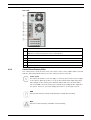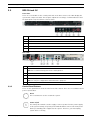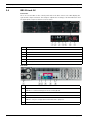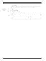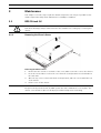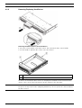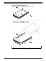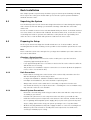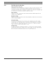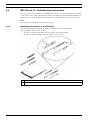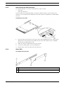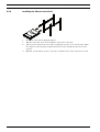
1
Bosch Recording Station Appliance
en
Hardware Installation Manual
Bosch Recording Station Appliance
Table of Contents | en
3
Table of Contents
1
Safety Precautions
5
1.1
General Safety Precautions
5
1.2
Electrical Safety Precautions
8
1.3
Important Notices
9
1.4
FCC & ICES compliance
1.5
EMC Compliance
10
1.6
ESD Precautions
10
1.7
Operating Precautions
11
2
System Overview
12
2.1
Introduction
12
2.2
BRS Tower
12
2.2.1
Control Panel Buttons/LEDs
13
2.3
BRS 19-inch 1U
15
2.3.1
Control Panel Buttons
15
2.3.2
Control Panel LEDs
16
2.3.3
Drive Carrier LEDs
16
2.3.4
Power Supply LEDs
16
2.3.5
Overheating
17
2.4
BRS 19-inch 2U
18
2.4.1
Control Panel Buttons
19
2.4.2
Control Panel LEDs
19
2.4.3
Drive Carrier LEDs
20
3
Maintenance
21
3.1
BRS 19-inch 1U
21
3.1.1
Removing the Chassis Cover
21
3.1.2
Removing/Replacing Hard Drives
22
3.1.3
System Fans
24
3.1.4
Power Supply
25
3.2
BRS 19-inch 2U
26
3.2.1
Removing the Chassis Cover
26
3.2.2
Removing/Replacing Hard Drives
27
3.2.3
System Fans
29
3.2.4
Power Supply
30
4
Rack Installation
32
4.1
Unpacking the System
32
4.2
Preparing for Setup
32
4.2.1
Choosing a Setup Location
32
4.2.2
Rack Precautions
32
4.2.3
General System Precautions
32
4.2.4
Rack Mounting Considerations
33
4.3
BRS 19-inch 1U - Rack Mounting Instructions
34
4.3.1
Identifying the Sections of the Rack Rails
34
4.3.2
Inner Rails/Inner Rail Extensions
35
Bosch Security Systems
9
Hardware Installation Manual
- | V1 | 2011.10
4
en | Table of Contents
Bosch Recording Station Appliance
4.3.3
Outer Rails
35
4.3.4
Installing the Chassis into a Rack
36
4.3.5
Installing the Chassis into a Telco rack
37
4.4
BRS 19-inch 2U - Rack Mounting Instructions
38
4.4.1
Separating the Sections of the Rack Rails
38
4.4.2
Inner Rails/Inner Rail Extensions
39
4.4.3
Outer Rails
39
4.4.4
Installing the Chassis into a Rack
40
5
Additional documentation
41
- | V1 | 2011.10
Hardware Installation Manual
Bosch Security Systems
Bosch Recording Station Appliance
Safety Precautions | en
1
Safety Precautions
1.1
General Safety Precautions
5
The following safety precautions must be observed:
Read, follow and retain instructions
All safety and operating instructions must be read and followed before installing the device.
Retain instructions for future reference.
Observe warnings
Observe all warnings on the device and in the Hardware Installation Manual.
Add-on devices
Do not use add-on devices that are not recommended by the product manufacturer as these
may cause hazards.
Installation notes
–
Do not place the device on an unstable mounting, tripod or similar. The device may fall to
the ground and seriously injure the user or be damaged itself.
–
Only use accessories that have been recommended by the manufacturer or are delivered
with the device.
–
–
Fit the device according to the manufacturer's instructions.
Exercise extreme caution when transporting the device on a trolley. Abrupt stopping,
extreme force effects and uneven surfaces may cause the device and the trolley to tip
over.
–
Keep the area around the system clean and free of clutter.
–
Place the chassis top cover and any system components that have been removed away
from the system or on a table so that they won't accidentally be stepped on.
–
While working on the system, do not wear loose clothing such as neckties and
unbuttoned shirt sleeves, which can come into contact with electrical circuits or be
pulled into a cooling fan.
–
Remove any jewelry or metal objects from your body, which are excellent metal
conductors that can create short circuits and harm you if they come into contact with
printed circuit boards or areas where power is present.
–
After accessing the inside of the system, close the system back up and secure it to the
rack unit after ensuring that all connections have been made.
–
The system is heavy when fully loaded. When lifting the system, two people at either end
should lift slowly with their feet spread out to distribute the weight. Always keep your
back straight and lift with your legs.
Cleaning
Unplug the device from the mains power supply before cleaning. Follow the instructions for
the device. Normally, cleaning can be carried out with a damp cloth. Do not use liquid
cleaners or cleaners in spray cans.
Service
Do not attempt to service the device yourself. You may be exposed to high electrical voltages
or other hazards if you open or remove covers. Servicing must be carried out by qualified
maintenance personnel.
Bosch Security Systems
Hardware Installation Manual
- | V1 | 2011.10
6
en | Safety Precautions
Bosch Recording Station Appliance
Damage requiring service.
Unplug the device from the mains power supply and arrange for the device to be serviced by
qualified personnel if:
–
The mains cable or mains plug is damaged.
–
Liquids or foreign bodies are present in the device.
–
The device has come into contact with water and/or has been exposed to extreme
environmental conditions (e.g. rain, snow etc.).
–
If the device does not work properly in spite of following the operating instructions, make
changes only to those operating elements that are described in the operating
instructions. Incorrect changes to other operating elements may cause damage requiring
extensive repair work to be carried out by qualified service personnel.
–
The device has fallen to the ground or the housing has been damaged.
–
A noticeable change in the performance of the device has occurred. In this case, the
device must be serviced.
Spare parts
If spare parts are required, service personnel must use spare parts that are recommended by
the manufacturer or correspond to the original parts. Using the wrong spare parts may result
in fire, electric shock or other hazards.
Safety test
When servicing or repair is complete, ask service personnel to carry out a safety test to ensure
that the device is working correctly.
Power source
The device must only be operated with the power source indicated on the label. If you are not
sure whether you can operate the device with a specific power source, ask the dealer from
whom you bought the device or your electricity provider.
For devices that are operated using external power units, only recommended and tested
power units should be used.
For devices that are operated using power units with limited power, the power unit must
conform to the EN 60950 standard. Other replacement power units may damage the device
and lead to fire or electric shock.
Coax grounding
If a cable system is connected to the device for outside use, ensure that the cable system is
grounded. Only for models available in the USA: Section 810 of the National Electrical Code,
ANSI/ NFPA No.70-1981, contains information on the correct grounding of the mounting, coax
grounding at a discharge device, the size of the ground conductors, the location of the
discharge device, connection to discharge electrodes and requirements regarding the
discharge electrodes.
Grounding or polarizing
This device may have a polarized AC plug (a plug with one pin broader than the other). With
this protection system, the plug can only be inserted into a socket in one way. If you are
unable to insert the plug fully into the socket, rotate it and try again. If you are still unable to
insert the plug, ask an electrician to replace the socket with a later model. Do not attempt to
bypass the polarized plug.
Alternatively, the device may have a 3-phase ground plug with a third (grounding) pin. With
this protection system, the plug can only be inserted into a grounded socket. If you are unable
to insert the plug into the socket, ask an electrician to replace the socket with a later model.
Do not attempt to bypass the grounded plug.
- | V1 | 2011.10
Hardware Installation Manual
Bosch Security Systems
Bosch Recording Station Appliance
Safety Precautions | en
7
Lightning
For added protection of the device during a storm, or when it is not used for a lengthy period
of time, unplug the device from the mains and disconnect the cable system. This prevents the
device being damaged by lightning or a power surge.
Location
The installation location should be quiet and have only limited access.
Devices for inside use
Water and damp — Do not use this device in the vicinity of water (e.g. in a damp cellar) or in
humid locations.
Entry of foreign bodies and liquids — Do not insert foreign bodies into the device openings
as you may touch parts that are at high-voltage or cause a short circuit, which may result in
fire or electric shock. Do not spill liquids on the device.
Mains cable and mains cable protectors — For devices that operate at 230 V AC, 50 Hz, the
input and output mains cables must conform to IEC publication 227 or IEC publication 245.
Mains cables should be laid in such a way that no one can step on them and no other objects
can be placed on top of them or leant against them. Particularly protect cables, plugs and
sockets as well as device entry points.
Overloading — Do not overload sockets and extension cables as this may result in fire or
electric shock.
Rack-mounting devices
Ventilation — This device should not be installed anywhere where correct ventilation cannot
be ensured or the manufacturer's instructions cannot be followed. The maximum operating
temperature for this device must not be exceeded.
Mechanical load — When installing the device in a rack, beware of hazards that may arise due
to unequal mechanical load.
WARNING!
Interruption of mains supply:
Voltage is applied as soon as the mains plug is inserted into the mains socket.
However, for devices with a mains switch, the device is only ready for operation when the
mains switch (ON/OFF) is in the ON position. When the mains plug is pulled out of the socket,
the supply of power to the device is completely interrupted.
WARNING!
Removing the housing:
To avoid electric shock, the housing must only be removed by qualified service personnel.
Before removing the housing, the plug must always be removed from the mains socket and
remain disconnected while the housing is removed. Servicing must only be carried out by
qualified service personnel. The user must not carry out any repairs.
WARNING!
Lithium battery:
Batteries that have been inserted wrongly can cause an explosion. Always replace empty
batteries with batteries of the same type or a similar type recommended by the manufacturer.
Dispose of empty batteries according to the manufacturer's instructions.
Bosch Security Systems
Hardware Installation Manual
- | V1 | 2011.10
8
en | Safety Precautions
Bosch Recording Station Appliance
CAUTION!
Electrostatically sensitive device:
To avoid electrostatic discharges, the CMOS/MOSFET protection measures must be carried
out correctly.
When handling electrostatically sensitive printed circuits, grounded anti-static wrist bands
must be worn and the ESD safety precautions observed.
NOTICE!
Installation should only be carried out by qualified customer service personnel in accordance
with the applicable electrical regulations.
Disposal
Your Bosch product has been developed and manufactured using high-quality materials and
components that can be reused.
This symbol means that electronic and electrical devices that have reached the end of their
working life must be disposed of separately from household waste.
In the EU, separate collecting systems are already in place for used electrical and electronic
products. Please dispose of these devices at your local communal waste collection point or at
a recycling center.
1.2
Electrical Safety Precautions
Basic electrical safety precautions should be followed to protect you from harm and the
system from damage:
–
Be aware of the locations of the power on/off switch on the chassis as well as the room's
emergency power-off switch, disconnection switch or electrical outlet. If an electrical
accident occurs, you can then quickly remove power from the system.
–
Do not work alone when working with high voltage components.
–
Power should always be disconnected from the system when removing or in stalling main
system components, such as the mainboard, memory modules and floppy drive. When
disconnecting power, you should first power down the system with the operating system
first and then unplug the power cords of all the power supply units in the system.
–
When working around exposed electrical circuits, another person who is familiar with the
power-off controls should be nearby to switch off the power if necessary.
–
Use only one hand when working with powered-on electrical equipment. This is to avoid
making a complete circuit, which will cause electrical shock. Use extreme caution when
using metal tools, which can easily damage any electrical components or circuit boards
they come into contact with.
–
Do not use mats designed to decrease static electrical discharge as protection from
electrical shock. Instead, use rubber mats that have been specifically designed as
electrical insulators.
–
The power supply power cords must include a grounding plug and must be plugged into
grounded electrical outlets. The unit has more than one power supply cord. Disconnect
both power supply cords before servicing to avoid electrical shock.
–
Mainboard replaceable soldered-in fuses: Self-resetting PTC (Positive Temperature
Coefficient) fuses on the mainboard must be replaced by trained service technicians
only. The new fuse must be the same or equivalent as the one replaced. Contact
technical support for details and support.
- | V1 | 2011.10
Hardware Installation Manual
Bosch Security Systems
Bosch Recording Station Appliance
Safety Precautions | en
9
CAUTION!
Mainboard Battery: There is a danger of explosion if the onboard battery is installed upside
down, which will reverse its polarities. This battery must be replaced only with the same or an
equivalent type recommended by the manufacturer (CR2032). Dispose of used batteries
according to the manufacturer's instructions.
CAUTION!
DVD-ROM Laser: Some systems come with a DVD-ROM drive. To prevent direct exposure to
the laser beam and hazardous radiation exposure, do not open the enclosure or use the unit in
any unconventional way.
CAUTION!
Class I Laser Product
Invisible laser radiation when open. Avoid exposure to beam.
1.3
Important Notices
Accessories - Do not place this unit on an unstable stand, tripod, bracket, or mount. The unit
may fall, causing serious injury and/or serious damage to the unit. Use only with the cart,
stand, tripod, bracket, or table specified by the manufacturer. When a cart is used, use
caution and care when moving the cart/apparatus combination to avoid injury from tip-over.
Quick stops, excessive force, or uneven surfaces may cause the cart/unit combination to
overturn. Mount the unit per the manufacturer's instructions.
1.4
FCC & ICES compliance
FCC & ICES Information
(U.S.A. and Canadian Models Only)
This device complies with part 15 of the FCC Rules. Operation is subject to the following
conditions:
–
–
this device may not cause harmful interference, and
this device must accept any interference received, including interference that may cause
undesired operation.
NOTE: This equipment has been tested and found to comply with the limits for a Class A
digital device, pursuant to Part 15 of the FCC Rules and ICES-003 of Industry Canada. These
limits are designed to provide reasonable protection against harmful interference when the
equipment is operated in a commercial environment. This equipment generates, uses, and
radiates radio frequency energy and, if not installed and used in accordance with the
instruction manual, may cause harmful interference to radio communications. Operation of
this equipment in a residential area is likely to cause harmful interference, in which case the
user will be required to correct the interference at his expense.
Intentional or unintentional modifications, not expressly approved by the party responsible
for compliance, shall not be made. Any such modifications could void the user's authority to
operate the equipment. If necessary, the user should consult the dealer or an experienced
radio/television technician for corrective action.
The user may find the following booklet, prepared by the Federal Communications
Commission, helpful: How to Identify and Resolve Radio-TV Interference Problems. This booklet
is available from the U.S. Government Printing Office, Washington, DC 20402, Stock No. 004000-00345-4.
Bosch Security Systems
Hardware Installation Manual
- | V1 | 2011.10
10
en | Safety Precautions
Bosch Recording Station Appliance
Informations FCC et ICES
(modèles utilisés aux États-Unis et au Canada uniquement)
Ce produit est conforme aux normes FCC partie 15. la mise en service est soumises aux deux
conditions suivantes :
–
–
cet appareil ne peut pas provoquer d'interférence nuisible et
cet appareil doit pouvoir tolérer toutes les interférences auxquelles il est soumit, y
compris les interférences qui pourraient influer sur son bon fonctionnement.
AVERTISSEMENT: Suite à différents tests, cet appareil s’est révélé conforme aux exigences
imposées aux appareils numériques de Classe A en vertu de la section 15 du règlement de la
Commission fédérale des communications des États-Unis (FCC). Ces contraintes sont destinées
à fournir une protection raisonnable contre les interférences nuisibles quand l'appareil est
utilisé dans une installation commerciale. Cette appareil génère, utilise et émet de l'energie
de fréquence radio, et peut, en cas d'installation ou d'utilisation non conforme aux
instructions, générer des interférences nuisibles aux communications radio. L’utilisation de ce
produit dans une zone résidentielle peut provoquer des interférences nuisibles. Le cas
échéant, l’utilisateur devra remédier à ces interférences à ses propres frais.
Au besoin, l’utilisateur consultera son revendeur ou un technicien qualifié en radio/télévision,
qui procédera à une opération corrective. La brochure suivante, publiée par la Commission
fédérale des communications (FCC), peut s’avérer utile : How to Identify and Resolve Radio-TV
Interference Problems (Comment identifier et résoudre les problèmes d’interférences de radio
et de télévision). Cette brochure est disponible auprès du U.S. Government Printing Office,
Washington, DC 20402, États-Unis, sous la référence n° 004-000-00345-4.
1.5
EMC Compliance
NOTICE!
This is a class A product. In a domestic environment this product may cause radio
interference, in which case the user may be required to take adequate measures.
1.6
ESD Precautions
Electrostatic Discharge (ESD) is generated by two objects with different electrical charges
coming into contact with each other. An electrical discharge is created to neutralize this
difference, which can damage electronic components and printed circuit boards. The
following measures are generally sufficient to neutralize this difference before contact is
made to protect your equipment from ESD:
–
Use a grounded wrist strap designed to prevent static discharge.
–
Keep all components and printed circuit boards (PCBs) in their antistatic bags until ready
for use.
–
Touch a grounded metal object before removing the board from the antistatic bag.
–
Do not let components or printed circuit boards come into contact with your clothing,
which may retain a charge even if you are wearing a wrist strap.
–
Handle a board by its edges only. Do not touch its components, peripheral chips, memory
modules or contacts.
–
When handling chips or modules, avoid touching their pins.
–
Put the mainboard and peripherals back into their antistatic bags when not in use.
–
For grounding purposes, make sure your computer chassis provides excellent
conductivity between the power supply, the case, the mounting fasteners and the
mainboard.
- | V1 | 2011.10
Hardware Installation Manual
Bosch Security Systems
Bosch Recording Station Appliance
1.7
Safety Precautions | en
11
Operating Precautions
The chassis cover must be in place when the system is operating to assure proper cooling.
Out of warranty damage to the system can occur if this practice is not strictly followed.
Bosch Security Systems
Hardware Installation Manual
- | V1 | 2011.10
12
en | System Overview
Bosch Recording Station Appliance
2
System Overview
2.1
Introduction
This manual applies to the following models:
2.2
–
Bosch Recording Station Tower (BRS Tower)
–
Bosch Recording Station 19-inch 1U (BRS 19-inch 1U)
–
Bosch Recording Station 19-inch 2U (BRS 19-inch 2U)
BRS Tower
Front view:
There are several LEDs on the control panel and on the drive carriers. The LEDs display the
system and component status. This chapter explains the meanings of all LED indicators and
the appropriate responses that need to be taken.
- | V1 | 2011.10
1
DVD writer
2
Overheat/Fan Fail
3
HDD
4
NIC
5
Power on/off
Hardware Installation Manual
Bosch Security Systems
Bosch Recording Station Appliance
System Overview | en
13
Rear view:
1
2
Mains connection 100 - 240 VAC, 50 - 60 Hz
Keyboard - Mouse
Note: We recommend using PS2 mouse and keyboard.
2.2.1
3
2x USB
4
Serial interface COM1
5
Do not use !
6
2x Ethernet (RJ45)
7
Monitor (DVI)
Control Panel Buttons/LEDs
The control panel is located on the front of the chassis. This section explains what each LED
indicates when illuminated and any corrective action you may need to take.
Power on/off
The main power button is used to apply or remove power from the power supply
to the system. When the power is on, the power button will be lighted by a blue
LED. Turning off the system power with this button will cause the blue LED to
turn off and will remove the main power, but will keep standby power supplied to
the system. Therefore, you must unplug system before servicing the system.
HDD
Indicates IDE channel activity. SAS/SATA drive activity when flashing.
NIC1
Indicates network activity on GLAN1 / 2 when flashing.
Bosch Security Systems
Hardware Installation Manual
- | V1 | 2011.10
14
en | System Overview
Bosch Recording Station Appliance
Overheat/Fan Fail
This LED indicates a fan failure when flashing.
When Continuously On (not flashing): This LED indicates an overheat condition
caused by cables obstructing the airflow in the system or the ambient room
temperature being too warm.
Correcting an Overheat/Fan Fail Condition
1.
Check the routing of the cables and move any cables the restrict airflow.
2.
Confirm that all fans are operating normally.
3.
Verify that the heatsinks are installed properly.
4.
If the chassis cover is not aligned correctly, the airflow may be disrupted. This leads to
overheating. Confirm that the chassis cover is placed correctly.
5.
- | V1 | 2011.10
This LED will remain active as long as the overheat condition exists.
Hardware Installation Manual
Bosch Security Systems
Bosch Recording Station Appliance
2.3
System Overview | en
15
BRS 19-inch 1U
Front view:
There are several LEDs on the control panel and on the drive carriers. The LEDs display the
system and component status. This chapter explains the meanings of all LED indicators and
the appropriate responses that need to be taken.
1
Overheat/Fan Fail
2
NIC1/NIC2
3
HDD
4
Power
5
Reset
6
Power on/off
Rear view:
1
2
2x mains connection 100 - 240 VAC, 50 - 60 Hz
Keyboard - Mouse
Note: We recommend using PS2 mouse and keyboard.
3
2x USB
4
Serial interface COM1
5
Monitor (VGA)
Note: Use only for configuration and maintenance purposes.
6
2.3.1
2x Ethernet (RJ45)
Control Panel Buttons
There are two push-buttons located on the front of the chassis. These are a reset button and a
power on/off button.
Reset
The reset button is used to restart the system.
Power on/off
The main power switch is used to apply or remove power from the power supply
to the system. Turning off system power with this button removes the main power
but keeps standby power supplied to the system. Therefore, you must unplug
system before servicing.
Bosch Security Systems
Hardware Installation Manual
- | V1 | 2011.10
16
en | System Overview
2.3.2
Bosch Recording Station Appliance
Control Panel LEDs
The control panel located on the front of the chassis has LEDs to provide you with critical
information related to different parts of the system. This section explains what each LED
indicates when illuminated and any action that may be required.
Overheat/Fan Fail
When this LED flashes it indicates a fan failure. When continuously on (not
flashing) it indicates an overheat condition, which may be caused by cables
obstructing the airflow in the system or the ambient room temperature being too
warm.
NIC2
Indicates network activity on GLAN2 when flashing.
NIC1
Indicates network activity on GLAN1 when flashing.
HDD
Indicates IDE channel activity. SAS/SATA drive, SCSI drive, and/or DVD-ROM drive
activity when flashing.
Power
Indicates power is being supplied to the system's power supply units. This LED
should normally be illuminated when the system is operating.
2.3.3
Drive Carrier LEDs
Your chassis uses SAS/SATA.
Each SAS/SATA drive carrier has two LEDs on the front of the SATA drive carrier.
–
Green: When illuminated, this green LED indicates drive activity. A connection to the
SATA backplane enables this LED to blink on and off when that particular drive is being
accessed.
–
Red: The red LED indicates an SAS/SATA drive failure. If one of the SAS/SATA drives fail,
you should be notified by your system management software.
2.3.4
Power Supply LEDs
This chassis includes redundant power supplies. The power supplies include LEDs in the rear
with the following definitions:
State
Indication
Solid Green
System is on.
Solid Amber
System is off and plugged in.
–
–
Solid Green: When illuminated, this green LED indicates that the power supply is on.
Solid Amber: When illuminated, the amber LED indicates the power supply is plugged in
and turned off, or the system is off but in an abnormal state.
- | V1 | 2011.10
Hardware Installation Manual
Bosch Security Systems
Bosch Recording Station Appliance
2.3.5
System Overview | en
17
Overheating
The section lists actions that should be taken in the unlikely event the system overheats.
If the system overheats, do the following:
1.
Use the LEDs to determine the nature of the overheating condition.
2.
Confirm that the chassis covers are installed properly.
3.
Check the routing of the cables and make sure all fans are present and operating
normally.
4.
Bosch Security Systems
Verify that the heatsinks are installed properly.
Hardware Installation Manual
- | V1 | 2011.10
18
en | System Overview
2.4
Bosch Recording Station Appliance
BRS 19-inch 2U
Front view:
There are several LEDs on the control panel and on the drive carriers. The LEDs display the
system and component status. This chapter explains the meanings of all LED indicators and
the appropriate responses that need to be taken.
1
Power Failure
2
Overheat/Fan Fail
3
NIC1/NIC2
4
HDD
5
Power
6
Reset
7
Power on/off
Rear view:
1
2x mains connection 100 - 240 VAC, 50 - 60 Hz
2
Keyboard - Mouse
Note: We recommend using PS2 mouse and keyboard.
3
2x USB
4
Serial interface COM1
5
Monitor (VGA)
Note: Use only for configuration and maintenance purposes.
6
- | V1 | 2011.10
2x Ethernet (RJ45)
Hardware Installation Manual
Bosch Security Systems
Bosch Recording Station Appliance
2.4.1
System Overview | en
19
Control Panel Buttons
There are two push-buttons located on the front of the chassis. These are a reset button and a
power on/off button.
Reset
The reset button is used to restart the system.
Power on/off
The main power switch is used to apply or remove power from the power supply
to the system. Turning off system power with this button removes the main power
but keeps standby power supplied to the system. Therefore, you must unplug
system before servicing.
2.4.2
Control Panel LEDs
The control panel located on the front of the chassis has LEDs to provide you with critical
information related to different parts of the system. This section explains what each LED
indicates when illuminated and any action that may be required.
Power Failure
When this LED flashes, it indicates a power failure in the power supply.
Overheat/Fan Fail
When this LED flashes it indicates a fan failure. When continuously on (not
flashing) it indicates an overheat condition, which may be caused by cables
obstructing the airflow in the system or the ambient room temperature being too
warm. Check the routing of the cables and make sure all fans are present and
operating normally. You should also check to make sure that the chassis covers
are installed. Finally, verify that the heatsinks are installed properly. This LED will
remain flashing or on as long as the overheat condition exists.
NiC2
Indicates network activity on GLAN2 when flashing.
NIC1
Indicates network activity on GLAN1 when flashing.
HDD
Indicates IDE channel activity in the SAS/SATA drive, SCSI drive, and/or DVD-ROM
drive activity when flashing.
Bosch Security Systems
Hardware Installation Manual
- | V1 | 2011.10
20
en | System Overview
Bosch Recording Station Appliance
Power
Indicates power is being supplied to the system's power supply units. This LED
should normally be illuminated when the system is operating.
2.4.3
Drive Carrier LEDs
Your chassis uses SAS/SATA.
Each SAS/SATA drive carrier has two LEDs.
–
Green: Each Serial ATA drive carrier has a green LED. When illuminated, this green LED
(on the front of the SATA drive carrier) indicates drive activity. A connection to the SATA
backplane enables this LED to blink on and off when that particular drive is being
accessed.
–
Red: The red LED indicates a SAS/SATA drive failure. If one of the SAS/SATA drives fail,
you should be notified by your system management software.
- | V1 | 2011.10
Hardware Installation Manual
Bosch Security Systems
Bosch Recording Station Appliance
3
Maintenance | en
21
Maintenance
This chapter covers the steps required to install components. The only tool you will need to
install components and perform maintenance is a Phillips screwdriver.
3.1
BRS 19-inch 1U
CAUTION!
Review the warnings and precautions listed in the manual before setting up or servicing this
chassis.
3.1.1
Removing the Chassis Cover
Removing the Chassis Cover
1.
Remove the two screws on each side of the cover, which secure the cover to the chassis.
2.
Press the release tabs to remove the cover from the locked position. Press both tabs at
the same time.
3.
Once the top cover is released from the locked position, slide the cover toward the rear
of the chassis.
4.
Lift the cover off the chassis.
CAUTION!
Except for short periods of time, do NOT operate the device without the cover in place. The
chassis cover must be in place to allow proper airflow and prevent overheating.
Bosch Security Systems
Hardware Installation Manual
- | V1 | 2011.10
22
en | Maintenance
3.1.2
Bosch Recording Station Appliance
Removing/Replacing Hard Drives
Removing Hard Drive Carriers from the Chassis
1. Press the release button on the drive carrier. This extends the drive carrier handle.
2. Use the handle to pull the drive carrier out of the chassis.
1
Drive carrier
2
Dummy drive
The drives are mounted in drive carriers to simplify their installation and removal from the
chassis. These carriers also help promote proper airflow for the drive bays.
CAUTION!
Except for short periods of time (swapping hard drives), do not operate the chassis without
the drive carriers.
- | V1 | 2011.10
Hardware Installation Manual
Bosch Security Systems
Bosch Recording Station Appliance
Maintenance | en
23
Installing a Hard Drive to the Hard Drive Carrier
1.
Remove the screws (2) securing the dummy drive to the carrier.
2.
Remove the dummy drive from the carrier.
3.
Install a new drive into the carrier with the printed circuit board side facing down so that
the mounting holes align with those in the carrier.
4.
Secure the hard drive by tightening all 6 screws.
1
Drive carrier
2
SAS/SATA hard drive
5.
Replace the drive carrier into the chassis bay, making sure that the drive carrier handle is
completely closed.
Bosch Security Systems
Hardware Installation Manual
- | V1 | 2011.10
24
en | Maintenance
3.1.3
Bosch Recording Station Appliance
System Fans
System fans provide cooling for the chassis. The system fans are powered from the system
board.
Adding a System Fan
1.
Turn off the power to the system and unplug the system from the outlet.
2.
Remove the dummy fan from the fan tray.
3.
Place the new fan into the vacant space in the housing while making sure the arrows on
the top of the fan (indicating air direction) point in the same direction as the arrows on
the other fans.
4.
5.
Connect the fan wires to the fan headers on the system board.
Power up the system and check that the fan is working properly before replacing the
chassis cover.
The chassis includes four pre-installed fans. One or two extra slots are available so that.
additional fans may be added.
Replacing a System Fan
1.
If necessary, open the chassis while the power is running to determine which fan has
failed. Never run the system for an extended period of time with the chassis open.
- | V1 | 2011.10
2.
Turn off the power to the system and unplug the AC power cord from the outlet.
3.
Remove the failed fan's wiring from the system board.
4.
Lift the failed fan from the chassis and pull it completely out from the system board.
Hardware Installation Manual
Bosch Security Systems
Bosch Recording Station Appliance
5.
Maintenance | en
25
Place the new fan into the vacant space in the housing while making sure the arrows on
the top of the fan (indicating air direction) point in the same direction as the arrows on
the other fans.
6.
Reconnect the fan wires to the exact same chassis fan headers as the previous fan.
7.
Reconnect the AC power cord, power up the system and check that the fan is working
properly before replacing the chassis cover.
3.1.4
Power Supply
The chassis includes a redundant, hot-swappable power supply. The power supply is autoswitching capable. This enables it to automatically sense and operate at a 100 V to 240 V input
voltage.
Power Supply Failure
If one power supply unit fails, the system will not shut down but you should replace the unit.
Replacing the unit can be done without powering down the system. Replacement units can be
ordered directly from Bosch RMA desk.
1
Release Tab
Replacing the Power Supply
1.
Power down the system and unplug the power cord. If your chassis includes a redundant
power supply (at least two power modules), you can leave the system running and
remove only one power supply.
Bosch Security Systems
2.
Push the release tab (on the back of the power supply) as illustrated.
3.
Pull the power supply out using the handle provided.
4.
Replace the failed power module with the same model.
5.
Push the new power supply module into the power bay until you hear a click.
6.
Plug the AC power cord back into the module and power up the system.
Hardware Installation Manual
- | V1 | 2011.10
26
en | Maintenance
3.2
Bosch Recording Station Appliance
BRS 19-inch 2U
CAUTION!
Review the warnings and precautions listed in the manual before setting up or servicing this
chassis.
3.2.1
Removing the Chassis Cover
Removing the Chassis Cover
1.
2.
Remove the two screws on each side of the cover, which secure the cover to the chassis.
Press the release tabs to remove the cover from the locked position. Press both tabs at
the same time.
3.
Once the top cover is released from the locked position, slide the cover toward the rear
of the chassis.
4.
Lift the cover off the chassis.
CAUTION!
Except for short periods of time, do NOT operate the system without the cover in place. The
chassis cover must be in place to allow proper airflow and prevent overheating.
- | V1 | 2011.10
Hardware Installation Manual
Bosch Security Systems
Bosch Recording Station Appliance
3.2.2
Maintenance | en
27
Removing/Replacing Hard Drives
Removing Hard Drive Trays from the Chassis
1.
Press the release button on the drive carrier. This extends the drive carrier handle.
2.
Use the handle to pull the drive out of the chassis.
1
Drive carrier
2
Dummy drive
The drives are mounted in drive carriers to simplify their installation and removal from the
chassis. These carriers also help promote proper airflow for the drive bays.
CAUTION!
Except for short periods of time (swapping hard drives), do not operate the system with the
hard drives removed from the bays.
Installing a Hard Drive to the Hard Drive Carrier
1.
Bosch Security Systems
Remove the screws securing the dummy drive to the carrier.
Hardware Installation Manual
- | V1 | 2011.10
28
en | Maintenance
Bosch Recording Station Appliance
2.
3.
Remove the dummy drive from the carrier.
Install a new drive into the carrier with the printed circuit board side facing down so that
the mounting holes align with those in the carrier.
4.
Secure the hard drive by tightening all 6 screws.
1
Drive carrier
2
SAS/SATA hard drive
5.
Replace the drive carrier into the chassis bay, making sure that the drive carrier handle is
completely closed.
- | V1 | 2011.10
Hardware Installation Manual
Bosch Security Systems
Bosch Recording Station Appliance
Maintenance | en
29
CAUTION!
Only the respective hard disk drives are recommended for use.
3.2.3
System Fans
System fans provide cooling for the chassis. The system fans are powered from the system
board.
Replacing a System Fan
1.
If necessary, open the chassis while the power is running to determine which fan has
failed. Never run the device for an extended period of time with the chassis open.
2.
Turn off the power to the system and unplug the system from the outlet.
3.
Remove the failed fan's power cord from the systemboard.
4.
Press the fan release tab to lift the failed fan from the chassis and pull it completely from
the chassis.
5.
Place the new fan into the vacant space in the housing while making sure the arrows on
the top of the fan (indicating air direction) point in the same direction as the arrows on
the other fans.
6.
Power up the system and check that the fan is working properly before replacing the
chassis cover.
Bosch Security Systems
Hardware Installation Manual
- | V1 | 2011.10
30
en | Maintenance
3.2.4
Bosch Recording Station Appliance
Power Supply
The chassis includes a redundant, hot-swappable power supply. The power supply is autoswitching capable. This enables it to automatically sense and operate at a 100 V to 240 V input
voltage.
Power Supply Failure
If one power supply unit fails, the system will not shut down but you should replace the unit.
Replacing the unit can be done without powering down the system. Replacement units can be
ordered directly from Bosch RMA desk.
Replacing the Power Supply
1.
If your chassis includes a redundant power supply (at least two power modules), you can
leave the system running and remove only one power supply. If your system has only one
power supply, you must power-down the system and unplug the power cord before
replacing the power supply.
- | V1 | 2011.10
2.
Push the release tab (on the back of the power supply) as illustrated.
3.
Pull the power supply out using the handle provided.
4.
Replace the failed power module with the same model.
Hardware Installation Manual
Bosch Security Systems
Bosch Recording Station Appliance
Maintenance | en
5.
Push the new power supply module into the power bay until you hear a click.
6.
Plug the AC power cord back into the module and power up the system.
31
Replacing the Power Distributor
Redundant chassis that are 2U or greater require a power distributor. The power distributor
provides failover and power supply redundancy. In the unlikely event you must replace the
power distributor, do following
1.
Power down the system and remove the plug from the wall socket or power strip.
2.
Remove all cable connections to the power supply from the motherboard, backplane, and
other components. Also, remove both power supplies.
3.
Locate the power distributor between the power supply and the fan row.
4.
Remove the three screws securing the power supply.
5.
Gently pull the power distributor from the chassis. Gently guide all the cables through
the power distributor housing.
6.
Slide the new power distributor module into the power distributor housing. Make that
you slide the cables through the bottom of the housing.
7.
Reconnect all the power cables, replace the power supply, and insert the plug into the
wall.
Bosch Security Systems
Hardware Installation Manual
- | V1 | 2011.10
32
en | Rack Installation
4
Bosch Recording Station Appliance
Rack Installation
This chapter provides a quick setup checklist to get your chassis up and running. Following
these steps in the order given should enable you to have the system operational within a
minimum amount of time.
4.1
Unpacking the System
You should inspect the box the chassis was shipped in and note if it was damaged in any way.
If the chassis itself shows damage you should file a damage claim with the carrier who
delivered it.
Decide on a suitable location for the rack unit that will hold your chassis. It should be situated
in a clean, dust-free area that is well ventilated. Avoid areas where heat, electrical noise and
electromagnetic fields are generated. You will also need it placed near a grounded power
outlet. Be sure to read the Rack and System Precautions in the next section.
4.2
Preparing for Setup
The box your chassis was shipped in should include two sets of rail assemblies, two rail
mounting brackets and the mounting screws you will need to install the system into the rack.
Note:
Please read this section in its entirety before you begin the installation procedure outlined in
the sections that follow.
4.2.1
Choosing a Setup Location
–
Leave enough clearance in front of the rack to enable you to open the front door
completely (approximately 25 inches).
–
Leave approximately 30 inches of clearance in the back of the rack to allow for sufficient
airflow and ease in servicing.
–
This product is for installation only in a restricted access location (dedicated equipment
rooms, service closets and the like).
4.2.2
Rack Precautions
–
Ensure that the leveling jacks on the bottom of the rack are fully extended to the floor
with the full weight of the rack resting on them.
–
In single rack installation, stabilizers should be attached to the rack.
–
In multiple rack installations, the racks should be coupled together.
–
Always make sure the rack is stable before extending a component from the rack.
–
You should extend only one component at a time - extending two or more simultaneously
may cause the rack to become unstable.
4.2.3
General System Precautions
–
Review the electrical and general safety precautions that came with the components you
are adding to your chassis.
–
Determine the placement of each component in the rack before you install the rails.
–
Install the heaviest system components on the bottom of the rack first, and then work up.
–
Use a regulating uninterruptable power supply (UPS) to protect the system from power
surges, voltage spikes and to keep your system operating in case of a power failure.
–
Allow the hot plug hard drives and power supply modules to cool before touching them.
–
Always keep the rack's front door and all panels and components closed when not
servicing to maintain proper cooling.
- | V1 | 2011.10
Hardware Installation Manual
Bosch Security Systems
Bosch Recording Station Appliance
4.2.4
Rack Installation | en
33
Rack Mounting Considerations
Ambient Operating Temperature
If installed in a closed or multi-unit rack assembly, the ambient operating temperature of the
rack environment may be greater than the ambient temperature of the room. Therefore,
consideration should be given to installing the equipment in an environment compatible with
the manufacturer’s maximum rated ambient temperature (Tmra).
Reduced Airflow
Equipment should be mounted into a rack so that the amount of airflow required for safe
operation is not compromised.
Mechanical Loading
Equipment should be mounted into a rack so that a hazardous condition does not arise due to
uneven mechanical loading.
Circuit Overloading
Consideration should be given to the connection of the equipment to the power supply
circuitry and the effect that any possible overloading of circuits might have on overcurrent
protection and power supply wiring. Appropriate consideration of equipment nameplate
ratings should be used when addressing this concern.
Reliable Ground
A reliable ground must be maintained at all times. To ensure this, the rack itself should be
grounded. Particular attention should be given to power supply connections other than the
direct connections to the branch circuit (i.e. the use of power strips, etc.).
Bosch Security Systems
Hardware Installation Manual
- | V1 | 2011.10
34
en | Rack Installation
4.3
Bosch Recording Station Appliance
BRS 19-inch 1U - Rack Mounting Instructions
This section provides information on installing the chassis into a rack unit. There are a variety
of rack units on the market, which may mean the assembly procedure will differ slightly. You
should also refer to the installation instructions that came with the rack unit you are using.
Note:
This rail will fit a rack between 26" and 33.5" deep.
4.3.1
Identifying the Sections of the Rack Rails
The chassis package includes two rack rail assemblies in the rack mounting kit.
Each assembly consists of two sections:
- | V1 | 2011.10
–
an inner fixed chassis rail that secures directly to the system chassis
–
an outer fixed rack rail that secures directly to the rack itself.
1
Rail Extension (Inner Rail is pre-installed on the chassis)
2
Outer Rails
Hardware Installation Manual
Bosch Security Systems
Bosch Recording Station Appliance
4.3.2
Rack Installation | en
35
Inner Rails/Inner Rail Extensions
The chassis includes a set of inner rails which are in two sections:
–
inner rails
–
inner rail extensions.
The inner rails are pre-attached and do not interfere with normal use of the chassis if you
decide not to use a 19-inch rack. Attach the inner rail extension to stabilize the chassis within
the rack.
Installing the Inner Rails
1.
Place the inner rail extensions on the side of the chassis aligning the hooks of the chassis
with the inner rail extension holes. Make sure the inner rail extension faces "outward"
just like the pre-attached inner rail.
2.
4.3.3
Slide the extension toward the front of the chassis.
3.
Secure the chassis with 2 screws as illustrated.
4.
Repeat steps 1-3 for the other inner rail extension.
Outer Rails
Assembling the Outer Rails
Bosch Security Systems
1
Secure to the front of the rack.
2
Attach the two sections of the outer rail together.
3
Secure to the rear of the rack.
Hardware Installation Manual
- | V1 | 2011.10
36
en | Rack Installation
Bosch Recording Station Appliance
Installing the Outer Rails to the Rack
1.
Attach the longer section of the outer rail to the outside of the shorter section of the
outer rail. You must align the pins with the slides. Both ends of the outer rail must face
the same direction in order to be secured to the rack (see also Section Assembling the
Outer Rails).
2.
Adjust both sections of the outer rail to the proper length so that the rail fits snugly
within the rack.
3.
Secure the longer section of the outer rail to the front of the rack with two M5 screws
and the shorter section to the rear side of the rack with two M5 screws.
4.
Repeat steps 1-4 for the remaining outer rail.
Locking Tabs
–
Both chassis rails have a locking tab, which serves two functions. The first is to lock the
system into place when installed and pushed fully into the rack, which is its normal
position. Secondly, these tabs also lock the system in place when fully extended from the
rack. This prevents the system from coming completely out of the rack when you pull it
out for servicing.
4.3.4
- | V1 | 2011.10
Installing the Chassis into a Rack
Hardware Installation Manual
Bosch Security Systems
Bosch Recording Station Appliance
1.
Rack Installation | en
37
Confirm that chassis includes the inner rails (A) and rail extensions (B). Also, confirm
that the outer rails (C) are installed on the rack.
2.
Line chassis rails (A and B) with the front of the rack rails (C).
3.
Slide the chassis rails into the rack rails, keeping the pressure even on both sides (you
may have to depress the locking tabs when inserting). When the system has been
pushed completely into the rack, you should hear the locking tabs "click" into the locked
position.
4.
(Optional) Insert and tighten the thumbscrews that hold the front of the chassis to the
rack.
4.3.5
Installing the Chassis into a Telco rack
To install the chassis into a Telco type rack, use two L-shaped brackets on either side of the
chassis (four total). First, determine how far follow the chassis will extend out the front of the
rack. Larger chassis should be positioned to balance the weight between front and back. Then
attach the two front brackets to each side of the chassis, then the two rear brackets
positioned with just enough space to accommodate the width of the telco rack. Finish by
sliding the chassis into the rack and tightening the brackets to the rack.
Bosch Security Systems
Hardware Installation Manual
- | V1 | 2011.10
38
en | Rack Installation
4.4
Bosch Recording Station Appliance
BRS 19-inch 2U - Rack Mounting Instructions
This section provides information on installing the chassis into a rack unit with the quickrelease rails provided. There are a variety of rack units on the market, which may mean the
assembly procedure will differ slightly. You should also refer to the installation instructions
that came with the rack unit you are using.
NOTE: This rail will fit a rack between 26" and 33.5" deep.
4.4.1
Separating the Sections of the Rack Rails
The chassis package includes two rail assemblies in the rack mounting kit. Each assembly
consists of two sections: an inner fixed chassis rail that secures directly to the chassis and an
outer fixed rack rail that secures directly to the rack itself.
- | V1 | 2011.10
1.
Locate the rail assembly in the chassis packaging.
2.
Extend the rail assembly by pulling it outward.
3.
Press the quick-release tab.
4.
Separate the inner rail extension from the outer rail assembly.
Hardware Installation Manual
Bosch Security Systems
Bosch Recording Station Appliance
4.4.2
Rack Installation | en
39
Inner Rails/Inner Rail Extensions
The chassis includes a set of inner rails in two sections:
–
inner rails
–
inner rail extensions.
The inner rails are pre-attached to the chassis, and do not interfere with normal use of the
chassis if you decide not to use a 19-inch rack. The inner rail extension is attached to the inner
rail to mount the chassis in the rack.
Installing the Inner Rails
1.
Place the inner rail extensions on the side of the chassis aligning the hooks of the chassis
with the rail extension holes. Make sure the extension faces "outward" just like the preattached inner rail.
2.
3.
Slide the extension toward the front of the chassis.
Secure the chassis with 2 screws as illustrated. Repeat steps for the other inner rail
extension.
4.4.3
Outer Rails
Outer rails attach to the rack and hold the chassis in place. The outer rails for the s chassis
extend between 30 inches and 33 inches.
Installing the Outer Rails to the Rack
1.
Secure the back end of the outer rail to the rack, using the screws provided.
2.
Press the button where the two outer rails are joined to retract the smaller outer rail.
3.
Hang the hooks of the rails onto the rack holes and if desired, use screws to secure the
front of the outer rail onto the rack.
4.
Bosch Security Systems
Repeat steps 1-3 for the remaining outer rail.
Hardware Installation Manual
- | V1 | 2011.10
40
en | Rack Installation
4.4.4
Bosch Recording Station Appliance
Installing the Chassis into a Rack
1.
Extend the outer rails as illustrated above.
2.
Align the inner rails of the chassis with the outer rails on the rack.
3.
Slide the inner rails into the outer rails, keeping the pressure even on both sides. When
the chassis has been pushed completely into the rack, it should click into the locked
position.
4.
- | V1 | 2011.10
Optional screws may be used to secure the to hold the front of the chassis to the rack.
Hardware Installation Manual
Bosch Security Systems
Bosch Recording Station Appliance
5
Additional documentation | en
41
Additional documentation
Use the Quick Installation Guide and the Software Installation Manual to configure the
system. Information regarding the operation of the Bosch Recording Station can be found in
the Operating Manual.
Documentation for Bosch Security System products can be found as follows:
www.boschsecurity.com > select your region and your country > select Product Catalog >
start a search for your product > select the product in the search results to show the existing
documents.
Bosch Security Systems
Hardware Installation Manual
- | V1 | 2011.10
42
en | Additional documentation
- | V1 | 2011.10
Bosch Recording Station Appliance
Hardware Installation Manual
Bosch Security Systems
Bosch Security Systems
Werner-von-Siemens-Ring 10
85630 Grasbrunn
Germany
www.boschsecurity.com
© Bosch Security Systems, 2011