1
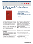
D9412GV2/D7412GV2
Operation and Installation Guide
EN
Control Panels
D9412GV2/D7412GV2 | Operation and Installation Guide | Trademarks
Trademarks
CoBox is a registered trademark of Lantronix.
Windows is a registered trademark of Microsoft
Corporation in the United States or in other countries.
Molex is a registered trademark of Molex
Incorporated.
Certifications and Approvals
The D9412GV2/D7412GV2 Literature Pack includes
the D9412GV2/D7412GV2 Approved Applications
Compliance Guide (P/N: F01U003639). Refer to this
guide for additional guidelines on installing the control
panels in Underwriters Laboratories Inc. (UL) and firespecific applications.
Listings and Approvals
UL
The D9412GV2 and D7412GV2 Control Panels are
UL Listed for Central Station, Local, Auxiliary,
Proprietary, and Household Fire Alarm, and Central
Station, Local, Police Station Connect, Household
Burglar Alarm and Encrypted line Security when
communicating via a network.
Department of Defense (DOD)
The D9412GV2/D7412GV2 was granted approval for
Department of Defense (DoD) installations in
Sensitive Compartmented Information Facilities
(SCIF).
Federal Communications
Commission (FCC) Rules
Part 15
This equipment was tested and found to comply with
the limits for a Class A digital device, pursuant to Part
15 of the FCC rules. These limits are designed to
provide reasonable protection against harmful
interference when the equipment is operated in a
commercial environment.
This equipment generates, uses, and can radiate
radio frequency energy; and if not installed and used
according to the instructions, can cause harmful
interference to radio communications.
Operation of this equipment in a residential area is
likely to cause harmful interference, in which case the
user is required to correct the interference at his or
her own expense.
Part 68
This equipment complies with Part 68 of FCC rules. A
label contains, among other information, the FCC
registration number and ringer equivalence number
(REN). If requested, this information must be provided
to the telephone company.
The D9412GV2 and D7412GV2 Control Panels are
registered for connection to the public telephone
network using an RJ38X or RJ31X jack.
The REN is used to determine the number of devices
that can be connected to the telephone line.
Excessive RENs on the telephone line may result in
the devices not ringing in response to an incoming
call. In most, but not all areas, the sum of the RENs
should not exceed five. To be certain of the number of
devices that may be connected to the line, as
determined by the RENs, contact the telephone
company to determine the maximum REN for the
calling area.
If you experience trouble with the D9412GV2 or
D7412GV2 Control Panel, please contact Bosch
Security Systems Customer Service for repair and
warranty information. If the trouble is causing harm to
the telephone network, the telephone company might
request that the equipment be removed from the
network until the problem is resolved. User repairs
must not be made, and doing so will void the user’s
warranty.
2
Bosch Security Systems, Inc. | 7/09 | F01U003641-04
D9412GV2/D7412GV2 | Operation and Installation Guide | Federal Communications Commission (FCC) Rules
.
If the D9412GV2 or D7412GV2 Control Panel causes
harm to the telephone network, the telephone
company attempts to notify you in advance. If
advance notice is not practical, the telephone
company notifies you as soon as possible. Also, you
will be advised of your right to file a complaint with the
FCC if you believe it is necessary.
The telephone company might make changes in its
facilities, equipment, operations, or procedures that
could affect the operation of the equipment. If this
happens, the telephone company provides advance
notice in order for the necessary modifications to be
made in order to maintain uninterrupted service.
This equipment cannot be used on public coin service
provided by the telephone company. Connection to
Party Line service is subject to state tariffs. (Contact
your state public utilities commission for information.)
FCC Registration Number: AJ9MUL-46532-AL-E
Service Center in USA:
Bosch ST Service Center
8601 East Cornhusker Hwy
Dock B
Lincoln, NE 68507 - 9702 USA
Ringer Equivalence: 0.4B
Bosch Security Systems, Inc. | 7/09 | F01U003641-04
3
D9412GV2/D7412GV2 | Operation and Installation Guide | Contents
Contents
1.0
2.0
2.1
2.2
3.0
3.1
3.1.1
3.1.2
3.2
3.3
3.3.1
3.3.2
3.3.3
3.3.4
3.3.5
3.3.6
3.3.7
3.3.8
3.3.9
3.3.10
3.3.11
3.3.12
3.3.13
3.3.14
3.3.15
3.3.16
3.3.17
4.0
4.1
4.2
4.3
4.4
4.5
4.5.1
4.5.2
4.5.3
4.5.4
4.5.5
4.6
4.6.1
4.6.2
4.6.3
4.6.4
4.6.5
4.7
4
Introduction..................................................7
Lightning Strikes .........................................8
Effects............................................................8
Precautions during Installation ......................8
Overview.......................................................9
Configuration and Parts.................................9
Parts List......................................................10
Parts Available by Separate Order..............10
Accessories .................................................10
Features in the D9412GV2 and D7412GV211
SDI Molex Connector ..................................11
Tip and Ring Posts ......................................11
Super Capacitor...........................................11
Telephone Line Sniff....................................12
Points...........................................................12
Areas and Accounts ....................................12
Digital Communicator ..................................12
Keypads.......................................................13
Keyswitch ....................................................13
Access Control ............................................13
Event Memory .............................................13
Event Log ....................................................14
Ground Fault Detection ...............................14
Ground Fault Detection Added Feature ......14
Conettix Functions.......................................14
Programming ...............................................14
Other Features ............................................14
Installation..................................................15
Installation Preparation................................15
Enclosure Options .......................................15
Mounting Enclosure.....................................15
Installing the Control Panel..........................16
Connecting Earth Ground............................16
Terminal 10..................................................16
Ground Fault Detect Enable ........................16
Enabling Ground Fault Detection ................17
D7212GV2 Ground Fault Specifications .....17
Locking the Reset Pin..................................18
Completing the Installation ..........................18
Charging the Battery....................................18
Installing and Wiring Detection Devices ......18
Installing Modules and Relays.....................19
Connecting the On-board Points and
Keypads.......................................................19
Powering Up ................................................19
Programming the Control Panel ..................19
4.8
4.9
4.10
5.0
5.1
5.1.1
5.1.2
5.2
5.2.1
5.2.2
5.2.3
5.2.4
5.2.5
5.2.6
6.0
6.1
6.2
6.3
6.4
6.4.1
6.4.2
6.4.3
6.4.4
7.0
7.1
7.2
7.3
7.4
7.5
7.6
7.7
7.8
7.9
7.10
7.11
7.11.1
7.11.2
7.11.3
7.11.4
8.0
8.1
8.2
8.3
8.4
Installing the Point Chart Label ................... 19
Testing the System ..................................... 19
Service Walk Test ....................................... 20
Power Supply ............................................ 23
Primary Power Terminals 1 and 2 .............. 23
Primary (AC) Power Circuit......................... 23
Installing the Transformer ........................... 23
Secondary Power Terminals....................... 23
Secondary (DC) Power ............................... 23
Installing the Battery ................................... 24
Replacing the Battery.................................. 26
Battery Supervision..................................... 26
Battery Charging Circuit.............................. 26
Battery Discharge and Recharge Schedule 27
Power Outputs........................................... 28
Circuit Protection......................................... 28
Total Available Power ................................. 28
Continuous Power Output Terminals 3, 8,
24, and 32 ................................................... 28
Programmable Power Output Terminals 6,
7, and 8 ....................................................... 28
Programming............................................... 28
Terminals 6 and 7 ....................................... 29
Fire System Power Formula ....................... 29
Terminal 8 ................................................... 29
Telephone Connections ........................... 30
Registration ................................................. 30
Notification .................................................. 30
Location....................................................... 30
Telephone Cord Connection ....................... 30
Phone LED (Red)........................................ 31
Operation Monitor LED (Green).................. 31
Dialing Format............................................. 31
Telephone Line Monitor .............................. 31
Called Party Disconnect.............................. 31
Communication Failure ............................... 31
D928 Dual Phone Line Switcher................. 32
Description .................................................. 32
Operation .................................................... 32
Installing the D928 ...................................... 33
D928 Status LEDs ...................................... 33
On-Board Points ....................................... 35
Terminals 11 to 22 Description ................... 35
Point Sensor Loops..................................... 35
Point Parameters ........................................ 35
Point Response Time.................................. 36
Bosch Security Systems, Inc. | 7/09 | F01U003641-04
D9412GV2/D7412GV2 | Operation and Installation Guide | Contents
.
8.5
9.0
9.1
9.1.1
9.1.2
9.1.3
9.1.4
9.1.5
9.2
9.3
9.3.1
9.3.2
9.3.3
9.3.4
9.3.5
9.3.6
9.3.7
9.3.8
9.4
9.4.1
9.4.2
9.4.3
9.4.4
9.4.5
9.4.6
9.4.7
9.5
10.0
10.1
10.1.1
10.1.2
10.1.3
10.1.4
10.2
10.2.1
10.2.2
10.2.3
11.0
11.1
11.2
11.2.1
11.2.2
Wiring Information for Installations Using
the Rothenbuhler 5110/4001-42 High
Security Bell.................................................36
Off-Board Points........................................39
Point (Zonex) Bus: D9412GV2 Terminals
and D7412GV2 Terminals ...........................39
POPIT Modules ...........................................39
POPEX Modules..........................................39
Missing Conditions ......................................39
Extra Point Events .......................................39
D9412GV2/D7412GV2 Responses to
Missing Point Conditions .............................40
D8125, D8127 and D9127 POPIT Modules 40
Installing the D8125 POPEX Module ..........43
Mounting ......................................................43
Wiring the D8125 to the Control Panel........43
Wiring POPITs to the Data Expansion
Loop.............................................................43
Wiring Data Expansion Loops to POPEX
Modules .......................................................44
POPIT Sensor Loops...................................44
POPIT Module Point Assignments ..............44
Program Record Sheet................................44
POPIT Labels ..............................................45
D8128D OctoPOPIT Module .......................45
Description...................................................45
Listings.........................................................46
Installation ...................................................47
Setting the OctoPOPIT Switches ................47
Mounting OctoPOPITs.................................48
Wiring OctoPOPITs .....................................48
OctoPOPIT Sensor Loops ...........................51
Testing Off-Board Points .............................52
Off-Board Relays .......................................53
D8129 OctoRelay ........................................53
Configuring the D8129 OctoRelay...............54
Relay Outputs..............................................54
Installation ...................................................54
Wiring Connections .....................................55
D811 Arm Status Relay Module ..................55
Relay Output................................................55
Installation ...................................................56
Wiring Connections .....................................56
Arming Devices .........................................58
Description...................................................58
Keypad Terminals 29 to 32 .........................58
Assigning an Address for the Keypad .........58
Installation ...................................................59
Bosch Security Systems, Inc. | 7/09 | F01U003641-04
11.3
11.4
11.4.1
11.4.2
11.4.3
11.4.4
12.0
12.1
12.2
12.3
12.3.1
12.3.2
12.4
D279A Independent Zone Control .............. 60
Keyswitch .................................................... 60
Description .................................................. 60
Programming............................................... 60
Installation ................................................... 60
Operation .................................................... 60
SDI Devices................................................ 62
Description .................................................. 62
Installation ................................................... 62
D9131A Parallel Printer Interface Module .. 62
Switch Settings............................................ 62
Supervision ................................................. 62
D9210B Wiegand Control Interface
Module ........................................................ 63
12.4.1 Access......................................................... 63
12.4.2 Switch Settings............................................ 63
12.5
SDI Address 80 ........................................... 63
12.5.1 Serial Interface Modules (SIMs).................. 63
12.5.2 Address Settings......................................... 63
12.5.3 Supervision ................................................. 64
12.6
SDI Address 88 ........................................... 64
12.6.1 D9133DC Direct Connect Programming
Module ........................................................ 64
12.6.2 Network Interface Modules ......................... 64
12.6.3 Address Settings......................................... 65
12.6.4 Supervision ................................................. 65
13.0
Programmer and Accessory
Connections .............................................. 66
13.1
Programmer Connector .............................. 66
13.2
Programmer Access Reports...................... 66
13.3
Accessory Connector.................................. 66
14.0
Faceplates.................................................. 67
14.1
D9412GV2 Faceplate ................................. 67
14.2
D7412GV2 Faceplate ................................. 68
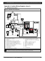
Appendix A: System Wiring Diagrams, Issue A . 69
A.1
D9412GV2 Control Panel ........................... 69
A.2
D7412GV2 Control Panel ........................... 72
Appendix B: Point Address Charts ...................... 75
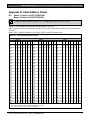
B.1
Zonex 1, Points 9 to 127 (D9412GV2);
Zonex 1, Points 9 to 75 (D7412GV2).......... 75
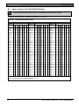
B.2
Zonex 2, Points 129 to 247 (D9412GV2
Only)............................................................ 76
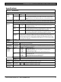
Specifications......................................................... 77
5
D9412GV2/D7412GV2 | Operation and Installation Guide | Contents
Figures
Figure 1:
Figure 2:
Figure 3:
Figure 4:
Figure 5:
Figure 6:
Figure 7:
Figure 8:
Figure 9:
Figure 10:
Figure 11:
Figure 12:
Figure 13:
Figure 14:
Figure 15:
Figure 16:
Figure 17:
Figure 18:
Figure 19:
Figure 20:
Figure 21:
Figure 22:
Figure 23:
Figure 24:
Figure 25:
Figure 26:
Figure 27:
Figure 28:
Figure 29:
Figure 30:
Figure 31:
Figure 32:
Figure 33:
Figure 34:
6
System Configuration..............................9
Enclosure Mounting ..............................15
Ground Fault Detection.........................16
Ground Fault Detect (S4)......................17
Area 5 Silent Alarm Relay in RPS.........17
Reset Pin...............................................18
D9412GV2 Service Walk Test Flow
Chart .....................................................21
D7412GV2 Service Walk Test Flow
Chart .....................................................22
Non-Power-Limited Wiring ....................25
Charging and Battery LEDs ..................26
RJ31X Wiring ........................................30
Phone Connector, Phone LED, and
Operation Monitor LED Locations.........30
D928 Dual Phone Line Switcher...........33
On-board Point Sensor Loop Wiring.....35
Rothenbuhler 5110/4001-42 High
Security Bell Wiring Configuration ........37
Wiring the Rothenbuhler 5110/4001-42
High Security Bell to the D9412GV2
or D7412GV2 Control Panel .................38
Connecting the D8125 POPEX to the
D9412GV2 Control Panel .....................41
Connecting the D8125 POPEX to the
D7412GV2 Control Panel .....................42
Program Record Sheet .........................45
D8128D OctoPOPIT Layout..................46
Connecting D8128D OctoPOPITs to
the D9412GV2 ......................................49
Connecting D8128D OctoPOPITs to
the D7412GV2 ......................................50
Wiring Multiple D8128Ds Using
Molex® Connectors ...............................51
D8128D OctoPOPIT Sensor Loops ......52
D8129 Connections to the D9412GV2 .53
D8129 Connections to the D7412GV2 .54
D811 Module Wiring to the
D9412GV2 ............................................56
D811 Module Wiring to the
D7412GV2 ............................................57
Power at Keypads.................................60
Keyswitch Wiring...................................61
D9133 Jumper Setting for Address 80..64
DX4010i DIP Switch Settings................64
DX4020 DIP Switch Settings ................65
Reset Pin...............................................66
Figure 35: Programmer and Accessory
Connections.......................................... 66
Figure 36: D9412GV2 Faceplate........................... 67
Figure 37: D7412GV2 Faceplate........................... 68
Figure 38: D9412GV2, Power Supply Side ........... 69
Figure 39: D9412GV2, Input Points and
Peripheral Devices ............................... 70
Figure 40: D9412GV2, SDI Devices...................... 71
Figure 41: D7412GV2, Power Supply Side ........... 72
Figure 42: D7412GV2, Input Points and
Peripheral Devices ............................... 73
Figure 43: D7412GV2, SDI Devices...................... 74
Tables
Table 1:
Table 2:
Table 3:
Table 4:
Table 5:
Table 6:
Table 7:
Table 8:
Table 9:
Table 10:
Table 11:
Table 12:
Table 13:
Table 14:
Table 15:
Table 16:
Table 17:
Table 18:
Table 19:
Table 20:
Table 21:
Table 22:
Table 23:
Table 24:
Table 25:
Table 26:
Table 27:
Related Documentation.......................... 7
GV2 Series Control Panel Differences ... 9
Compatible Accessories....................... 10
Software Version Compatibility of
D6500 MPU and Line Cards ................ 13
Compatible Keypads and Command
Centers ................................................. 13
Ground Fault Impedance
Specifications ....................................... 17
Battery Discharge and Recharge
Schedule............................................... 27
Charging Status and Low Battery
LEDs..................................................... 27
Phone Cord Lengths............................. 33
Point Parameters.................................. 35
POPEX Modules................................... 39
Extra Point Events ................................ 39
Off-Board Point Errors .......................... 40
Data Expansion Loop Wire
Specifications ....................................... 43
D8128D OctoPOPIT Switch Settings
for D9412GV2 and D7412GV2............. 47
Switch 5 Settings for Line Termination. 47
Terminal Strip Connections .................. 48
D8129 OctoRelay Switch Settings ....... 54
Number of D8128Ds Used with D8129s
.............................................................. 55
Keypad Address Settings ..................... 58
Keypad Connections ............................ 59
SDI Device Connections ...................... 62
Printer Address Switch Settings ........... 62
Address Switch Settings for Access
Control Module ..................................... 63
Zonex 1 Point Address Chart ............... 75
Zonex 2 Point Address Chart ............... 76
Specifications ....................................... 77
Bosch Security Systems, Inc. | 7/09 | F01U003641-04
D9412GV2/D7412GV2 | Operation and Installation Guide | 1.0
Introduction
.
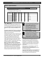
1.0 Introduction
This manual addresses the operation and installation of the D9412GV2 and D7412GV2 Control Panels.
Throughout this guide, the words “control panel” refer to both control panels (D9412GV2 and D7412GV2).
Table 2 on page 9 provides an overview of the differences in the control panels.
To obtain any of the documents in Table 1, contact Bosch Security Systems, inc. Technical
Support and request the documentation by its corresponding part number.
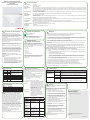
Table 1:
Related Documentation
Product Type
Control Panels
Keypads
Programming
Tools
Expansion
Devices
Name of Documentation∗
Part Number
∗
D9412GV2/D7412GV2 Release Notes
D9412GV2/D7412GV2 Approved Applications Compliance Guide∗
F01U003637
F01U003639
D9412GV2/D7412GV2 Troubleshooting Guide∗
D9412GV2/D7412GV2 Operation and Installation Guide (this document) ∗
D9412GV2/D7412GV2 Program Entry Guide∗
F01U011024
F01U003641
D9412GV2/D7412GV2 Program Record Sheet∗
UL Certificated Bank Safe and Vault Applications Technogram
F01U003635
9000/G/GV2 Series Technical Service Note: UL Smoke Detector Compatibility∗
D1255RB/D1256RB/D1257RB Installation Instructions∗
D1255/D1255B Installation Instructions
D1256/D1257 Installation Instructions
D1260/D1260B Installation Guide
D1260/D1260B Owner’s Manual
D720 Series Installation Instructions
D279A Operation and Installation Instructions
Security System Owner's Manual
GV2 Series Owner's Manual Supplement
RPS Installation and Operation Guide
D5200 Operation Manual
D8128D Installation Guide∗
D8125MUX Operation & Installation Guide∗
D9210B Operation and Installation Guide∗
∗
F01U003636
73-07302-000
33284
F01U011791
74-06819-000
74-06925-000
48101
50410
74-06918-000
46458
71-06633-000
F01U063791
4998141259
74-06176-000
41323
36796
32206
These products meet the requirements for UL 864 Commercial Fire applications..
Bosch Security Systems, Inc. | 7/09 | F01U003641-04
7
D9412GV2/D7412GV2 | Operation and Installation Guide | 2.0 Lightning Strikes
2.0 Lightning Strikes
The control panels are designed to significantly
reduce electromagnetic interference and malfunction
generally caused by lightning.
2.1
Effects
Any electronic system can be struck directly by
lightning or be adversely affected by a lightning strike
near the system. When lightning strikes, several
things happen:
• An electromagnetic wave spreads from the point
of the strike inducing high voltages in nearby
conductors.
• The voltage changes substantially on electrical
grounds near the lightning strike.
• High voltages are induced upon anything directly
struck by lightning.
Symptoms of installations that lightning might strike or
affect are Missing Trouble, Missing Alarm, or Point
Bus Trouble events. Occasionally, Reboot and
Watchdog events might be sent because the control
panel tried to reset itself.
Electronic systems, including control panels, cannot
be completely immune to direct or indirect lightning
strikes; however, some proven installation practices
might greatly reduce the risk of undesirable affects.
2.2
Precautions during Installation
To minimize the risk of undesirable effects from
lightning strikes on high risk installations that use a
point-bus technology:
• Do not run wiring outside the building.
• If you must install the unit in a metal building,
keep the wiring at least 0.61 m (2 ft) away from
external metal surfaces.
• Earth ground the unit correctly. Do not use an
electrical ground or telephone ground.
• Avoid running wires near telephone, data, or
power lines inside a building. Historical evidence
shows that locating control panel wiring at least
0.61 m (2 ft) away from telephone, data, or power
lines is successful at minimizing lightning
damage. When your data lines must cross the
path of AC or other wiring, cross the lines
perpendicularly.
8
Bosch Security Systems, Inc. | 7/09 | F01U003641-04
D9412GV2/D7412GV2 | Operation and Installation Guide | 3.0
Overview
.
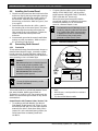
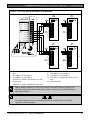
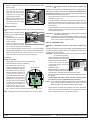
3.0 Overview
3.1
Configuration and Parts
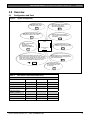
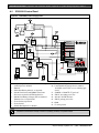
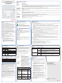
Figure 1:
System Configuration
D8129 OctoRelay pr ovides alarm
and auxiliary relay output.
(Other functions available.)
D9210B Modules can be
used for access control.
Each D8128D OctoPOPIT combines
eight POPIT points in one module.
DX4020 allows communciation
over a Local or Wide Area Network
(LAN/WAN).
Control
Panel
D8125, ISW-D8125CW,
D8125INV, or
D8125MUX Interface
used for point expansion.
D928 Module allows the control
panel to monitor two phone lines.
On-Board Points
1 to 8
Use keypads or keyswitches to arm the control
panel by area. Each control panel can have up to eight
areas. Each area can have its own account number or
areas can be grouped together with a common account
number. Points of protection are assigned to areas.
D8132 Modules (two 12 VDC batteries)
provide additional power for keypads and
other powered devices.
D9131A Module connects
to a parallel printer to print
the event log.
Table 2:
GV2 Series Control Panel Differences
Features
D9412GV2
D7412GV2
D7212GV2
Access Control
Yes - 8 doors
Yes - 2 doors
No
Arm/Disarm Passcodes
249
99
99
Cards/Tokens
996
396
N/A
16
4
4
3
1
1
Number of Points
246
75
40
Number of Relays
128
64
24
Number of Areas
8
8
4
Passcode-Protected
Custom Functions
Number of Printers
Bosch Security Systems, Inc. | 7/09 | F01U003641-04
9
D9412GV2/D7412GV2 | Operation and Installation Guide | 3.0 Overview
3.1.1
•
Parts List
The D9412GV2 andD7412GV2 Control Panels are
shipped assembled from the factory with the following
parts:
Literature Pack
• D9412GV2/D7412GV2 Program Record Sheet
(P/N: F01U003635)
• 9000/G/GV2 Series Technical Service Note: UL
Smoke Detector Compatibility (P/N: 33284)
• 7000/9000 Series Point Chart Label
(P/N: 79-06660-000)
Assembly
• PC board
• Faceplate shield
• Mounting skirt
• One #6 x 1/4-in. screw
3.1.2 Parts Available by Separate Order
Order the following components separately to
complete a basic eight-point installation.
The D1260 and D1260B Keypads must
have firmware version 1.03 or higher for
use with the D9412GV2 and D7412GV2.
3.2
D1255B, D1255, D1256, D1260, D1260B
Keypad, or D720 Keypad
• D1255RB Fire Keypad, D1256RB Fire Keypad, or
D1257RB Fire Alarm Annunciator
• D1640 Transformer
• D126 or D1218 Battery
• D161 or D162 Phone Cord (order two cords if
using the D928 Dual Phone Switcher)
• D8103, D8108A, or D8109 Enclosure
Configured packages are also available. Please
consult the Bosch Security Systems, Inc. Product
Catalog.
The following literature is available in a separate
literature package for dealers.
• D9412GV2/D7412GV2 Operation and Installation
Guide (P/N: F01U003641)
• D9412GV2/D7412GV2 Approved Applications
Compliance Guide (P/N: F01U003639)
• D9412GV2/D7412GV2 Program Entry Guide
(P/N: F01U003636)
• D9412GV2/D7412GV2 Program Record Sheet
(P/N: F01U003635)
The D9412GV2/D7412GV2 Troubleshooting Guide is
available in hard copy only (P/N: F01U011024),
CD-ROM only (P/N: F01U012325), or hard copy with
enclosed CD-ROM (P/N: F01U012326).
Accessories
Refer to the Bosch Security Systems, Inc. product catalog for additional information.
Table 3:
Compatible Accessories3
Model
D122/D122L
D125B
D127
D129
D130
D185
D192G
D279A
D720
D720R
D720W
D928
D1255RB
D1256RB
D1257RB
D1218
D1255/D1255B
D1255R
10
Title
Dual Battery Harness
Powered Loop Interface Module
Reversing Relay
Dual Class A Initiation Circuit Module
Relay Module
Reverse Polarity Module
Bell Circuit Supervision Module
Independent Zone Control (On-Board and OctoPOPIT
Points)
Keypad (Area LED)
LED Keypad (red)
LED Keypad (white)
Dual Phone Line Switcher
Fire Keypad
Fire Keypad
Fire Alarm Annunciator
12 V, 17.2 Ah Rechargeable Battery
Keypads (General Purpose)
Text Keypad (red)
UL 864
X
X
X
X
X
X
X
X
X
X
X
Fire
X
X
X
X
X
X
X
Intrusion
X
X
X
X
X
X
X
X
X
X
X
X
X
X
X
X
X
X
X
X
X
X
X
X
X
X
X
X
Bosch Security Systems, Inc. | 7/09 | F01U003641-04
D9412GV2/D7412GV2 | Operation and Installation Guide | 3.0
Overview
.
Table 3:
Compatible Accessories (continued)3
Model
D1255W
D1256
D1257
D1260/D1260B1
D1640
D8004
D8125
D8125MUX
ISW-D8125CW2
D8125INV2
D8128D
D8129
D8130
D8132
D9127U/T
D9131A
D9210B
ZX776Z
ZX794Z
ZX865
ZX938Z
ZX970
1
2
3
Title
Text Keypad (white)
Fire Keypad (Command Center)
Fire Alarm Annunciator
Keypads
16.5 VAC 40 VA Transformer
Transformer Enclosure
POPEX Module
Multiplex Bus Interface
Commercial Wireless Interface Module
Inovonics Wireless Interface Module
OctoPOPIT Module
OctoRelay Module
Release Module
Battery Charger Module
POPIT Module
Parallel Printer Interface Module
Access Control Interface Module
PIR Motion Sensor [15 m (50 ft)] with POPIT
PIR Motion Sensor [24 m (80 ft)] with POPIT
UL 864
X
X
X
X
X
X
X
X
X
PIR/Microwave Motion Sensor [+1.7°C (+35°F)] with POPIT
PIR Motion Sensor [18 m (60 ft)] with POPIT
Fire
X
X
X
X
X
X
X
X
X
X
X
X
X
X
X
Intrusion
X
X
X
X
X
X
X2
X2
X
X
X
X
X
X
X
X
X
X
X
PIR/Microwave Motion Sensor [+1.7°C (+35°F)] with POPIT
Version 1.03 or above
The ISW-D8125CW and the D8125INV were not investigated by UL. Do not use the ISW-D8125CW or D8125INV in UL Listed
installations.
Where the fire alarm transmitter is sharing on-premise communications equipment, the shared equipment must be UL Listed (ITE
or fire protective signaling).
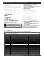
3.3
Features in the D9412GV2 and
D7412GV2
3.3.1
SDI Molex Connector
Use the SDI Molex Connector to connect easily an
SDI device with the SDI bus, without needing to
disconnect wires connected to the SDI terminals.
Possible applications include:
• Connecting a DX4010i to program the control
panel with Remote Programming Software (RPS)
at the premises
• Connecting a keypad to test the control panel.
Do not connect the D5200 Programmer to
the SDI Molex connector.
3.3.2
Tip and Ring Posts
The tip and ring posts allow connecting a phone or
buttset for the purpose of troubleshooting
communications between the control panel and the
central station. This connection allows monitoring of
the dial tone, handshaking tones from the receiver,
and communications signals.
3.3.3
Super Capacitor
The D9412GV2 and D7412GV2 have a capacitor
called Super Cap. This component preserves the
parameters stored in the control panel’s RAM chip
when the lithium battery is replaced. The Super Cap
can retain voltage for up to 30 minutes after the
lithium battery is removed.
Bosch Security Systems, Inc. | 7/09 | F01U003641-04
11
D9412GV2/D7412GV2 | Operation and Installation Guide | 3.0 Overview
Plan to replace the lithium battery after 3 to 5 years of
continual service.
When replacing the lithium battery,
ensure that you disconnect the primary
AC power and secondary battery power
from the control panel before you remove
the old battery. Then install the new
battery and connect the primary AC and
secondary battery power to the control
panel.
3.3.4
Telephone Line Sniff
The D9412GV2 and D7412GV2 control panels
monitor the phone line for the programmed
supervision interval before indicating a phone line
trouble. If trouble occurs, refer to the
D9412GV2/D7412GV2 Troubleshooting Guide (P/N:
F01U011024).
3.3.5
Points
The Bosch Security Systems, Inc. D9412GV2 Control
Panel provides up to 246 points of protection. The
D7412GV2 Control Panel provides up to 75 points of
protection. Point programming parameters determine
the control panel’s response to open and shorted
conditions on the sensor loop for the point. Several
options allow individual point programming to customfit the protection to the installation.
Points 1 to 8 are located on the circuit board (onboard points). They are standard sensor loops. The
remaining off-board points are POPIT points using
D8128D OctoPOPITs, D8125 POPEX Modules and
D9127 or D8127 POPITs. MUX devices can also be
used with D8125MUX or wireless transmitters with the
ISW-D8125CW and D8125INV.
3.3.6
Areas and Accounts
The system supports up to eight separate areas. You
can assign all points to a single area or distribute
them over as many as eight areas.
The control panel is armed and disarmed by area,
and several areas can be armed and disarmed with
one menu function. A passcode can also be assigned
an authority level that allows a user to arm an area
from a remote keypad in another area. Assigning
each area its own account number creates eight
separate accounts in one control panel. Assigning the
same account number to different areas groups them
together in a single account.
Area options include exit tone and delay, separate fire
and burglary outputs, and multiple opening and
closing windows. Area type can be used to create
area interdependencies for arming purposes.
3.3.7
Digital Communicator
The control panel uses a built-in digital communicator
to send reports to the receiver. The control panel
sends reports in either the Modem IIIa2 or binary
frequency shift keying (BFSK) format. The
microprocessor unit (MPU) and line cards for the
D6500 receiver must have the correct software
revision installed to accept Modem IIIa2 reports from
the control panel. Refer to Table 4. All software
versions for the D6600 can be used with the control
panel.
12
Bosch Security Systems, Inc. | 7/09 | F01U003641-04
D9412GV2/D7412GV2 | Operation and Installation Guide | 3.0
Overview
.
Table 4:
Software Version Compatibility of
D6500 MPU and Line Cards
MPU
D6510
D6511
Line Card
D6540
D6541
Software Version
8.00 and higher
1.04 and higher
7.44 and higher
1.03 and higher
The control panel connects to an RJ31X or RJ38X
jack for telephone line seizure. Connecting to the
RJ31X complies with FCC regulations for using the
public telephone network. The control panel can be
programmed to direct reports to four separate
telephone numbers. Adding the D928 Dual Phone
Line Switcher Module allows connecting and
supervising a second telephone line.
The system can route groups of Event Reports to four
different destinations. Each report group can be
programmed to send reports to one or more
destinations. Primary and backup reporting paths can
be programmed for each destination and each report
group. A custom option allows specification of
individual Event Reports to be sent.
3.3.8
Keypads
Up to 32 unsupervised keypads can be connected to
the system. The available power, number of
supervised keypads, and number of areas covered
affect the total number of keypads that can be
connected.
The system can supervise up to eight keypads. The
control panel sends a Serial Device Trouble Report,
SDI FAILURE in the Modem IIIa2 format or TROUBLE
ZN D in the BFSK format, if it loses communication
with a supervised keypad.
More than eight keypads can be added, but
supervision of only eight for is possible. Table 5 on
page 13 shows the keypads that are compatible with
the D9412GV2 and D7412GV2 Control Panels. Refer
to Keypad in the D9412GV2/D7412GV2 Program
Entry Guide (P/N: F01U003639) for complete details
on programming keypad options.
UL requires all Fire System keypads to be
supervised.
Bosch Security Systems, Inc. | 7/09 | F01U003641-04
Table 5:
Compatible Keypads and Command
Centers
Model
D1255/
D1255B/D
1255RB
D1256/
D1256RB
D1257/
D1257RB
D1260/
D1260B
D720/
D720B
Display
16-character
alphanumeric
Application
Fire/Burglary/Acces
s
16-character
alphanumeric
16-character
alphanumeric
4-line by 20character
8 LED
Fire
3.3.9
Fire
Fire/Burglary
Fire/Burglary
Keyswitch
Maintained or momentary closure devices such as
keyswitches allow any of the available areas to be
armed or disarmed. Point programming determines
the loop responses and which area a keyswitch
controls.
3.3.10 Access Control
The D9412GV2 can control eight access doors (each
requiring the optional D9210B Wiegand Control
Interface Module) with up to 996 uniquely identified
cards or tokens. The D7412GV2 can control two
access doors with up to 396 uniquely identified cards
or tokens. Any of the following can grant access:
• Wiegand-style access control device (card
reader) connected to the D9210B Access Control
Interface Module
• Request to enter (RTE) or request to exit (REX)
input
• Unlock command on a keypad
The access control features of the D9412GV2 and
D7412GV2 can deny access during armed periods.
The control panel can also grant access only to
certain authorized users depending on whether the
area is master armed, perimeter armed, or disarmed.
Programming for automatic disarming when
designated authorized users are granted access is
also possible.
3.3.11 Event Memory
The system uses event memory to store events for
each area. A D1255, D1255B, D1255RB, D1260, or
D1260B Keypad assigned to an area allows viewing
of the events for the area. The control panel clears
the events for an area from event memory and starts
storing new events when the area is master armed.
13
D9412GV2/D7412GV2 | Operation and Installation Guide | 3.0 Overview
3.3.12 Event Log
3.3.16 Programming
The system stores from 500 to 1000 events and event
modifiers from all areas in its event log. Event
modifiers add information about an event to the log.
Some events are always followed by a modifier. For
example, the system adds at least two items to the
log each time an area is armed or disarmed, the Open
(or Close) event and an event modifier showing the
previous arming state.
Use the Bosch Security Systems D5200 Programmer
or the Remote Programming Software (RPS) to
program the D9412GV2 and D7412GV2 Control
Panels. Refer to the D9412GV2/D7412GV2 Program
Entry Guide (P/N: F01U003636) for programming
options.
All events and their modifiers can be stored even if
the control panel does not send a report for them. The
log can be viewed at a keypad, printed locally using
the D9131A Parallel Printer Interface Module and a
parallel printer, or uploaded using Remote
Programming Software (RPS).
For a list of the log events and event modifiers, refer
to the appendix in the user’s guide for the keypad.
3.3.13 Ground Fault Detection
The Earth Ground Terminal on the control panels is
electrically isolated from all other terminals to allow
the D9412GV2 and the D7412GV2 to detect ground
fault conditions. A Ground Fault Detect Enable switch
(S4) is located just under Terminal 10, Earth Ground,
on the control panel. Refer to Section 4.5.2 Ground
Fault Detect Enable on page 16 for information on
operating this function.
3.3.14 Ground Fault Detection Added Feature
3.3.17 Other Features
D9412GV2 and D7412GV2 Control Panels have
many programmable features. Some of the features
are listed below. Complete details on all features are
in the D9412GV2/D7412GV2 Program Entry Guide
(P/N: F01U003636).
• Supervision of AC (primary power), battery
(secondary power), Zonex and SDI buses, central
processing unit (CPU), up to three printers, and
two telephone lines
• Automatic System Test Reports
• Remote access for programming, diagnostics,
and log uploads using the remote programming
software (RPS)
• Fire alarm verification
• Programmable alarm output
• Programmable relay output using the D8129
OctoRelay Module
• Opening and closing windows
• Skeds (scheduled events)
When Ground Fault Detect is enabled (S4 closed),
Points 1 to 8 can be used for non-powered fireinitiating devices such as heat detectors, four-wire
smoke detectors, and pull stations. A D125B Powered
Loop Interface or a D129 Dual Class A Interface
Module is not required when connecting the nonpowered fire-initiating devices to Points 1 to 8.
3.3.15 Conettix Functions
The D6600 Conettix System supports data network
communications. Conettix allows the D6600 receiver
to connect to network topologies, specifically
Ethernet. Conettix also allows this receiver to process
messages to and from most networks using TCP/IP
protocols. Connecting to a data network is possible
using the COM4 or COM1 connection from the D6600
receiver to the D6680 Network Adapter. Alarm control
panels can send reports through telephone lines or
Ethernet and token-ring data networks to the D6600
receiver and then to the central station automation
software or the network printer through a local area
network (LAN) or wide area network (WAN). The
network can monitor the status of alarm control
panels.
14
Bosch Security Systems, Inc. | 7/09 | F01U003641-04
D9412GV2/D7412GV2 | Operation and Installation Guide | 4.0
Installation
.
4.2
4.0 Installation
4.1
Installation Preparation
This section contains a general installation procedure
and refers to other sections of the document for
detailed instructions.
Review this document and the D9412GV2/D7412GV2
Program Entry Guide (P/N: F01U003636) before
beginning the installation to determine the hardware
and wiring requirements for the features used.
Have the following documentation available when
reading through this guide:
• D9412GV2/D7412GV2 Program Record Sheet
(P/N: F01U003635)
• Security System Owner’s Manual
(P/N: 71-06633-000) and GV2 Series Owner’s
Manual Supplement (P/N: F01U0063791)
• Installation manual for keypad, command center,
or annunciator (D1255, D1255B, D1255RB,
D1256, D1256RB, D1257, D1257RB, D1260,
D1260B, D720, or D720B)
Before installation, become familiar with the operation
of the D5200 Programmer or the RPS.
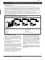
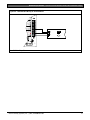
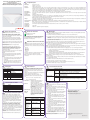
Figure 2:
Enclosure Options
Mount the control panel assembly in any of the Bosch
Security Systems, Inc. enclosures listed:
• D8103 Universal Enclosure (tan)
• D8109 Fire Enclosure (red)
• D8108A Attack Resistant Enclosure (tan)
Refer to the D9412GV2/D7412GV2 Approved
Applications Compliance Guide (P/N: F01U003639)to
determine if the application requires a specific
enclosure.
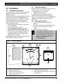
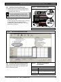
4.3
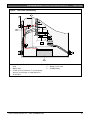
Mounting Enclosure
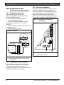
1. Run the necessary wiring throughout the
premises.
2. Mount the enclosure in the desired location. Use
all five enclosure mounting holes. Refer to
Figure 2.
3. Pull the wires into the enclosure.
Electromagnetic interference (EMI) can
cause problems on long wire runs. For
more information, refer to “Noise on Wire”
in the General Wiring Troubleshooting
section of the D9412GV2/D7412GV2
Troubleshooting Guide
(P/N: F01U011024).
Enclosure Mounting
1
3
2
2
4
7
8
3
5
9
6
12345-
Point chart label
Mounting skirt hooks (2)
Module mounting holes (12)
Tamper switch mounting holes (5)
Skirt mounting hole (1)
Bosch Security Systems, Inc. | 7/09 | F01U003641-04
6789-
Enclosure mounting holes (5)
Mounting skirt hook holes (2)
Back of D9412GV2/D7412GV2 Control Panel
Lock down tab
15
D9412GV2/D7412GV2 | Operation and Installation Guide | 4.0 Installation
4.4
Installing the Control Panel
1. Place the control panel over the inside back of the
enclosure, aligning the large rectangular openings
of the mounting skirt with the mounting hooks of
the enclosure. Slide the control panel down so
that it hangs on the hooks. Refer to Figure 2, Item
2 on page 15.
2. Remove the tape from the #6 x 1/4-in. screw in
the mounting tab on the control panel. The screw
passes through the mounting tab and into the
skirt mounting hole in the enclosure. Tighten the
screw to secure the control panel in the
enclosure.
3. Connect earth ground to the control panel before
making any other connections. Refer to Section
4.5 Connecting Earth Ground.
4.5
•
If a ground fault condition occurs, the keypads
display SERVC GND FAULT and the control
panel transmits a GROUND FAULT TROUBLE,
AREA 1 (Modem IIIa2 format only).
When the control panel recognizes that the
ground fault condition is corrected, and remains
corrected for between 5 to 45 consecutive
seconds, a Restoral Report is sent.
The D9412GV2 and D7412GV2 Control
Panels log and print a Ground Fault event
as a Trouble Point 256 if communicating
in Modem IIIa2 format. If communicating
in BFSK format, the control panels
generate an Alarm Zone 5 event.
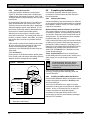
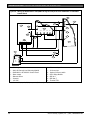
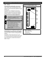
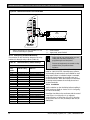
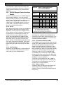
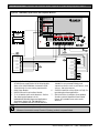
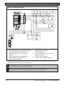
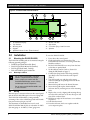
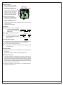
Figure 3:
Ground Fault Detection
Connecting Earth Ground
4.5.1 Terminal 10
To help prevent damage from electrostatic charges or
other transient electrical surges, connect the system
to earth ground at Terminal 10 before making other
connections. Recommended earth ground references
are a grounding rod or a cold water pipe.
1
2
Caution:
Do not use telephone or electrical ground
for the earth ground connection. Use
1.8 mm (14 AWG) to 1.5 mm (16 AWG)
wire when making the connection.
Do not connect other control panel
terminals to earth ground.
3
GROUND FAULT DETECT
Enabled
Disabled
RED
PHONE
LED
S4
ON when
communicating
OFF when idle
PHONE LINE SEIZED
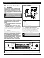
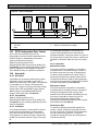
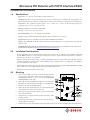
4.5.2
Ground Fault Detect Enable
TIP
TELCO CORD
MODEL D161
RING
To meet UL 864 requirements, enable
Ground Fault Detect.
A ground fault is a circuit impedance to earth ground.
The control panel has a ground fault detection circuit
that, when enabled, detects ground faults on
Terminals 1 to 9 and 11 to 32. The control panel also
detects and annunciates ground faults on any device
connected to it.
1 - With S4 closed, control panel detects ground
faults.
2 - With S4 open, control panel does not detect
ground faults.
3 - S4, Ground fault detect enable
Control Panels with Firmware before Version 7.03
• To enable ground fault detection, the Ground
Fault Detect Enable jumper (S4) (Figure 3) must
be locked (closed) and a non-zero value must be
entered in the Area 5 Silent Alarm Relay. When
jumper S4 is in the unlocked (open) position, the
control panel does not detect ground fault
conditions.
16
Bosch Security Systems, Inc. | 7/09 | F01U003641-04
D9412GV2/D7412GV2 | Operation and Installation Guide | 4.0
.
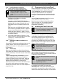
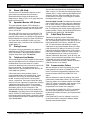
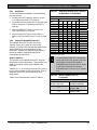
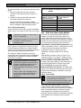
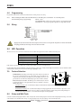
4.5.3
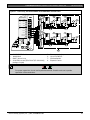
Enabling Ground Fault Detection
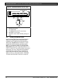
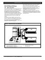
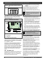
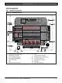
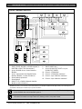
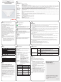
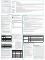
Figure 4:
To enable the Ground Fault Detect Enable feature:
1. Lock (close) the S4 Ground Fault Detect Pin on
the control panel (Figure 4).
Ground Fault Detect (S4)
F01U003643-01
YEL
RED
Charging Status
Low Battery - 12.1 VDC
D9412GV2
Commercial Protected-Premises Control Panel
Refer to the D9412GV2/D7412GV2 Approved Applications Compliance Guide (P/N: F01U003639)
For System Wiring Diagram, Issue A and for Compatible Smoke Detectors
CLASS 2 TRANSFORMER
16.5 VAC 40 VA 60 Hz
Model D1640
Internally Fused - Do not short
Requires Unswitched Outlet
Do not share with other equipment
POWER SUPPLY REQUIREMENTS
The Power Supply provides a maximum of 1.4 Amps for the Control Panel and all
Accessory Devices. For System Loading, refer to the D9412GV2/D7412GV2
Operation and Installation Guide (P/N: F01U003641).
All external connections except Terminal 5 (battery positive) are inherently power
limited. Requirements for battery standby time might reduce allowable output.
+ AUX POWER
CAUTION: Refer to the D9412GV2/D7412GV2 Operation and Installation Guide
BATTERY NEGATIVE ONLY
WARNING!
PROGRAMMABLE
ALARM OUTPUTS
Terminals
6 and 7
RELAY B
SWITCHED AUX
Terminal
8
RELAY C
PHONE
LED
4.5.4
DATA BUS B
Point 1 Point 2
Point 3 Point 4
Point 5 Point 6
Point 7 Point 8
27
ZONEX OUT 2
26
26
ZONEX IN 2
25
25
ZONEX POWER +
24
24
ZONEX COMMON
23
D5200/D5360
PROG
PROG CONN
CONN
Point 8
S3 Option
Open =AB-12 UL
Bell Box 220 KΩ
PHONE LINE SEIZED
RING
ZONEX IN 1
Closed = 1KΩ EOL
Normal Operation
ON when
communicating
OFF when idle
TELCO CORD
MODEL D161
ZONEX OUT 1
2
VOLTAGE RANGES
3.7 - 5.0 VDC Short 0.0 - 1.3 VDC
2.0 - 3.0 VDC
Open
Normal
COMMON
N.F.P.A.
Style 4.0
Signaling
Line
Circuits
D9412GV2 Control Panel is UL Listed For Central Station, Local, Auxiliary, Proprietary, and
Household Fire Alarm, and Central Station, Local, Police Station Connect, Household Burglar Alarm
and Encrypted Line Security when communicating via a network.
11
12
13
14
1 - Locked (Closed)
Figure 5:
DATA BUS A
GREEN
BLACK
Battery: Replace every 3 to
5 years with one or two Model
D126 or D1218 12V Lead Acid
Batteries.
Multi-Battery installation requires
Model D122/D122L Dual Battery
Harness. Improper installation can
be a fire hazard.
POWER +
YELLOW
System is intended to be checked by a Qualified Technician at least every 3 years.
The types of initiating circuits the control panel has been approved for are A, M, W, SS.
The types of signaling the control panel has been approved for are DAC, OT, NC
COMMON
RED
RED
This equipment should be installed in accordance with the NFPA 70 (National Electrical Code)
and NFPA 72 (National Fire Alarm Code) for Local, Central Station, Proprietary and Household Fire
Warning Systems and under the limits of the Local Authority Having Jurisdiction (National Fire
Protection Association, Battermarch Park, Quincy, MA 02269). Printed information describing
proper installation, operation, testing, maintenance, evacuation planning and repair service is to
be provided with this equipment.
EARTH GROUND
GROUND FAULT DETECT
Enabled
Disabled
TIP
PERIPHERAL DEVICE CONNECTIONS
(P/N: F01U003641) for Power Requirements relating to Terminals 6 and 7 .
Maximum charging current 1.4 A
BATTERY POSITIVE ONLY
RELAY A
SDI Connector
Reset Pin
Disable All Except
Battery
Reset
Pin
Charging
Programming
Disable And
all except
Battery
Charging and Programming
Minimum system requirements for Classification in accordance with ANSI/SIA CP-01-2000:
UL Listed and Classified control unit Model D9412GV2, D7412GV2, or D7212GV2;
UL Listed and Classified keypad Model D1256, D1257, D1260, D1255, D1255R, or D1255RW;
UL Listed Local Bell
10.2 VDC - Battery Load Shed
CAUTION: Avoid damage to Panel.
Do not connect 24 V to terminals.
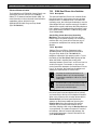
2. Program the Area 5 Silent Alarm Relay to a nonzero value (1 to 128).
In remote programming software (RPS), the Area
5 Silent Alarm Relay is located in RELAY
PARAMETERS, Area Wide Relays, and Silent
Alarm Area 5 (Figure 5).
1
Incorrect wiring will
damage this equipment.
Suitable for dry indoor
use only.
Devices powered by the
AUX power output must
be supervised.
LEDs Off When Normal
If your control panel has Version 7.02
firmware or earlier, you must do Step 2.
Installation
15
16
17
18
19
20
21
22
GRN
2 - Unlocked (Open)
Area 5 Silent Alarm Relay in RPS
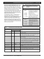
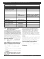
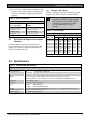
D7212GV2 Ground Fault Specifications
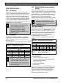
Table 6 provides the impedance specifications for
detecting ground faults when any terminal or field
wiring is shorted to ground.
Bosch Security Systems, Inc. | 7/09 | F01U003641-04
Table 6:
Impedance
<300 Ω
300 Ω to
200>kΩ
> 200 kΩ
Ground Fault Impedance
Specifications
Control Panel Detects Ground Fault
Yes
Detection depends upon the terminal
No
17
D9412GV2/D7412GV2 | Operation and Installation Guide | 4.0 Installation
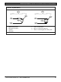
4.5.5
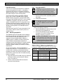
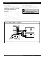
Locking the Reset Pin
4.6
Locking the reset pin disables the control panel
(Figure 6). When the control panel is disabled, the
system ignores the keypads and points. CALL FOR
SERVICE appears in keypad displays when the pin is
locked down.
On-board relays (Terminals 6 and 7) and off-board
relays deactivate when the control panel is reset.
Terminal 8 has power when the relay is deactivated.
Activation interrupts power at that terminal. The onboard relay (Terminal 8) remains deactivated when
the reset pin is locked in the disable position.
Releasing the reset pin from the closed position
resets the control panel. The control panel resets all
its timers, counters, indexes, and buffers. Any points
that restore after a reset do not generate Restoral
Reports.
If the reset pin is placed in the disable position when
all areas are armed, there must be an entry in the
Answer Armed program item. Refer to RPS
Parameters in the D9412GV2/D7412GV2 Program
Entry Guide
(P/N: F01U003636).
Locking the pin in the disable position applies power
to the control panel and charges the battery while the
detection devices and keypads are installed.
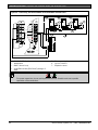
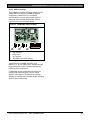
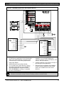
Figure 6:
If not already complete, make the earth ground
connection to Terminal 10 and lock the reset pin in
the closed position.
4.6.1
On-board Buzzer Sounds at Power Up and Reset:
The system performs a series of self-diagnostic tests
of hardware, software, and programming at power up
and at reset. The buzzer on the control panel sounds
during the tests. The self-diagnostics tests complete
in approximately 1 to 3 seconds.
If the control panel fails any test, the buzzer continues
sounding and a System Trouble message appears at
the keypads. Refer to Problems Found during Self
Diagnostics in the D9412GV2/D7412GV2/D7212GV2
Installation and Troubleshooting Quick Reference
Guide (P/N: F01U003638) for a description of each
system trouble message.
Touch Terminal 10 First: If the on-board buzzer
sounds briefly when the control panel is touched, any
static charge you carry discharges to the control
panel.
Avoid electrostatic discharge. Always
touch Terminal 10, the earth ground
connection, before beginning work on the
control panel.
If the control panel receives an electrostatic
discharge, it might generate Watchdog Reset and
Param Fail events.
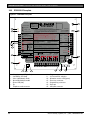
4.6.2
Reset Pin
Disable All Except Battery
Charging And Programming
PERIPHERAL DEVICE CONNECTIONS
POWER +
32
YELLOW
DATA BUS A
31
GREEN
DATA BUS B
30
BLACK
COMMON
29
Charging the Battery
Connect the battery, then the transformer to allow the
control panel to charge the battery while you complete
the installation. Refer to Section 5.0 Power Supply on
page 23 for instructions.
Reset Pin
1
RED
Completing the Installation
2
Installing and Wiring Detection Devices
Install and wire detection devices and keypads at their
locations throughout the premises. Do not connect
the control panel yet.
Section 8.0 On-Board Points on page 35 contains
instructions for wiring the on-board points to detection
devices. Section 11.0 Arming Devices on page 58
contains instructions for wiring the keypads.
Instructions for wiring the off-board point POPIT
sensor loops are found in the instructions packaged
with the POPIT modules.
1 - Reset pin locked (closed).
2 - Reset pin normal (open).
18
Bosch Security Systems, Inc. | 7/09 | F01U003641-04
D9412GV2/D7412GV2 | Operation and Installation Guide | 4.0
.
4.6.3 Installing Modules and Relays
1. Power down the unit by unplugging the
transformer and disconnecting the battery.
Always power down the unit when
installing modules or relays, or when
making wiring connections to the control
panel.
2.
Install and wire any modules required for the
installation as described in the module’s
installation instructions.
Instructions for the D8125 POPEX Module,
D8128D OctoPOPIT Module, D8129 OctoRelay
Module, D811 Arm Status Relay Module, and
D928 Dual Phone Line Switcher appear in this
guide.
Refer to Section 9.0 Off-Board Points on page
39 for D8125 and D8128D instructions. Refer to
Section 10.0 Off-Board Relays on page 53 for
D8129 and D811 instructions. Refer to Section
7.11 D928 Dual Phone Line Switcher on page 32
for D928 instructions.
3. If using the power outputs at Terminals 7 or 8,
refer to Section 6.4 Programmable Power Output
Terminals 6, 7, and 8 on page 28 for
instructions.
4.6.4 Connecting the On-board Points and
Keypads
Connect the on-board points and keypad wiring to the
system. Refer to Section 8.0 On-Board Points on
page 35 and Section 11.0 Arming Devices on page 58
for instructions.
4.6.5 Powering Up
Reconnect the battery, then plug in the transformer.
The buzzer sounds for two seconds when the control
panel is powered up. Leave the reset pin in the locked
position.
Yellow Charging Status LED Remains Lit: If the
yellow charging status LED remains lit after five
minutes of powering up the control panel, either the
battery is deeply discharged or too many powered
devices were connected to the control panel.
Combined continuous current draw for Terminals 3, 8,
24, and 32, and the accessory connector cannot
exceed 1.4 A. Refer to Section 6.0 Power Outputs on
page 28 for help.
Bosch Security Systems, Inc. | 7/09 | F01U003641-04
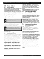
4.7
Installation
Programming the Control Panel
If the control panel is not already programmed, review
the D9412GV2/D7412GV2 Program Entry Guide
(P/N: F01U003636). Ensure that all accessory
modules for desired features are available for
installation. Place the reset pin in the locked position
to copy or send information to and from the control
panel.
Use the D5200 Programmer or the RPS to load a
custom program into the control panel.
Move the reset pin to the normal position refer to
(Figure 6 on page 18). The control panel sends
Reboot and Battery Reports to the receiver if
programmed for reporting.
4.8
Installing the Point Chart Label
The point chart label is required for fire
systems with verifications points.
A point chart label is included in the literature pack.
Install the point chart label for fire or combined fireand-burglary systems that use verification points.
Use the D9412GV2/D7412GV2 Program Record
Sheet (P/N: F01U003635) to gather the necessary
information for completing the point chart. Fill out the
label and install it on the inside of the enclosure door
(refer to Figure 2 on page 15).
Avoid smearing the entries on the chart.
Use the peel-off backing to press the
label in place.
4.9
Testing the System
After installing and programming the control panel,
test the system completely. Test the control panel and
all devices for proper operation.
Test after initially programming the control
panel.
To meet UL 864 requirements, perform a
full system test after any subsequent
programming session.
Refer to Section 4.10 Service Walk Test on page 20
for complete Service Walk Test instructions.
Clear after Test: To clear the event memory and
report buffer, momentarily close the reset pin. Events
stored in the control panel’s event log are not cleared.
19
D9412GV2/D7412GV2 | Operation and Installation Guide | 4.0 Installation
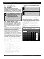
4.10
Service Walk Test
The Service Walk Test differs from the standard Walk
Test. In the standard Walk Test, POPITs whose
switches are set for a point number not programmed
in the control panel do not appear in the test. In the
Service Walk Test, POPITs whose switches are set
for a point number that is not programmed in the
control panel do appear in the test.
The Service Walk Test allows a user to walk test all
246 points from a control-panel-wide keypad,
regardless of the point index type.
A Service Walk Test can also be initiated by accountwide or area-wide keypads but test only those points
that are within the scope of the keypad that initiated
the function. The Service Walk Test does not test
points in armed areas.
Only Walk Test Start and Walk Test End
are reported to the central station.
The D9131A can be configured for local
printing. Refer to the D9412GV2/
D9412GV2 Program Entry Guide
(P/N: F01U003636).
During a Service Walk Test, the summary
alarm and summary fire remain off,
because there are no Fire or Burg alarm
conditions to summarize. The P# Relay
Response Type feature operates as
programmed.
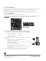
Service Walk Test Procedure.
The D7412GV2 does not include the
Service Walk Test in the Service Menu.
Enabling the Service Walk Test function
in the Function List provides access to
the Service Walk Test in the D7412GV2.
4. The display shows ### PTS TO TEST .Test the
first detection device.
5. When a detection device is faulted, the keypad
emits a brief tone and displays the point text of
the point tested for 60 seconds. After 60 seconds,
the display returns to the ### PTS TO TEST
message.
Extra Points display default text: If the switches on
a POPIT are set incorrectly to a point number that is
not in the program for the control panel, the default
text for that point number (PT ###) appears when the
point is faulted. Refer to the control panel’s program
record sheet for the default text for all points.
Faulting the point a second time produces the tone
and shows the point text, but does not decrease the
count in the ## PTS TO TEST message.
5. To see the points that remain untested during the
Service Walk Test:
a. Press [ESC] when point text appears. The
display shows ## PTS TO TEST.
b. Press the [ESC] key. VIEW UNTESTED ?
appears.
c.
Press [ENT]. ## PTS UNTESTED appears.
d. Press [NEXT] to see a list of the points that
have not yet been tested. Move through this
list by pressing the [NEXT] key.
Refer to Figure 7 on page 21 and Figure 8 on page 22
for Service Walk Test options. Refer to the Walk Test
procedures in the GV2 Series Owner’s Manual
Supplement (P/N: F01U063791) when using a D1260
or D1260B Keypad.
e. To resume the Service Walk Test, press
[ESC]. ## PTS UNTESTED appears.
1. Choose a keypad to conduct the test. Ensure that
the display shows the idle disarmed text.
6. After the last point is tested, 0 PTS TO TEST
appears. Press [ESC]. The display shows ALL
PTS TESTED briefly before returning to idle text.
2. Press the [MENU] key to enter the Function List.
Press [NEXT] repeatedly until the SERVICE
WALK ? prompt appears.
3. Press [ENT], or press [9][9] followed by [ENT] to
reach the Service Menu to access the Service
Walk Test.
f.
Press [ESC]. ## PTS TO TEST appears.
g. Resume testing points. To end the Service
Walk Test, press [ESC] twice.
The Service Walk Test, when performed
on a D7412GV2, cannot display “0 PTS
TO TEST” because the D7412GV2 is
physically unable to connect to the
second POPEX Module (used for Points
129-247).
Automatic time-out returns the system to
idle text: If there is no point or keypad
activity for 20 min., the Service Walk Test
ends automatically. The keypad returns to
idle text.
20
Bosch Security Systems, Inc. | 7/09 | F01U003641-04
D9412GV2/D7412GV2 | Operation and Installation Guide | 4.0
Installation
.
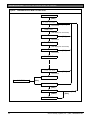
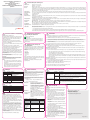
Figure 7:
D9412GV2 Service Walk Test Flow Chart
SERVICE WALK?
[ENT]
246 PTS TO TEST
Test a device
[ESC]
POINT TEXT
(Text displays for 60 seconds)
245 PTS TO TEST
[ESC]
Test a device
POINT TEXT
(Text displays for 60 seconds)
244 PTS TO TEST
[ESC]
Test a device
POINT TEXT
1 PTS TO TEST
[ESC]
Test a device
0 PTS TO TEST
IDLE TEXT
[ESC]
VIEW UNTESTED?
[ENT]
# PTS UNTESTED
[NEXT]
[ESC]
[ESC]
POINT TEXT
Bosch Security Systems, Inc. | 7/09 | F01U003641-04
21
D9412GV2/D7412GV2 | Operation and Installation Guide | 4.0 Installation
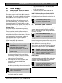
Figure 8:
D7412GV2 Service Walk Test Flow Chart
SERVICE WALK?
[ENT]
75 PTS TO TEST
Test a device
[ESC]
POINT TEXT
(Text displays for 60 seconds)
74 PTS TO TEST
[ESC]
Test a device
POINT TEXT
(Text displays for 60 seconds)
73 PTS TO TEST
[ESC]
Test a device
POINT TEXT
1 PTS TO TEST
[ESC]
Test a device
0 PTS TO TEST
IDLE TEXT
[ESC]
VIEW UNTESTED?
[ENT]
# PTS UNTESTED
[NEXT]
[ESC]
[ESC]
POINT TEXT
22
Bosch Security Systems, Inc. | 7/09 | F01U003641-04
D9412GV2/D7412GV2 | Operation and Installation Guide | 5.0
Power Supply
.
5.0 Power Supply
5.1
Primary Power Terminals 1 and 2
5.1.1
Primary (AC) Power Circuit
The primary source is a 16.5 VAC, 40 VA, internallyfused transformer (Bosch Security Systems, Inc.
Model D1640). The control panel draws 200 mA when
idle and 300 mA when in an alarm state. The total
available auxiliary current is 1.4 A.
Transient suppressors and spark gaps protect the
circuit from power surges. This protection relies on
the ground connection at Terminal 10. Ensure that
you connect Terminal 10 to a proper ground. Refer to
Section 4.5 Connecting Earth Ground on page 16.
AC Power Failure
The system indicates an AC power failure when
Terminals 1 and 2 do not have power. The AC Fail
Time program item sets the number of minutes or
seconds without AC power before the control panel
acknowledges the failure and the number of minutes
or seconds after the power returns before the control
panel acknowledges restored power. Refer to the
D9412GV2/D7412GV2 Program Entry Guide
(P/N: F01U003636) for additional information about
AC Fail Time and UL 864 requirements.
5.1.2
Installing the Transformer
Do not short-circuit the terminals of the
transformer: Shorting the terminals
opens the internal fuse, causing
permanent failure. Connect the
transformer to Terminals 1 and 2 of the
control panel before plugging it into the
power source.
1. Use 1.22 mm (18 AWG) wire (minimum) to
connect the transformer to the control panel.
The wire length should be as short as possible.
The maximum length is 15 m (50 ft.). Connect the
battery and plug in the transformer.
2. Route telephone and sensor loop wiring away
from any AC conductors, including the
transformer wire.
AC wiring can induce noise and low level voltage
into adjacent wiring. Route data wiring away from
AC and telephone wiring.
4. Plug the transformer into an unswitched, 120
VAC,
60 Hz power outlet only.
5. Secure the transformer to the outlet with the
screw provided.
D8004 Transformer Enclosure Required for Fire
Systems: Use the D8004 Transformer Enclosure for
the D1640 Transformer in fire and combined fire and
burglary applications.
Check with the Authority Having
Jurisdiction (AHJ) about mounting
transformers on specific circuits.
5.2
Secondary Power Terminals
5.2.1
Secondary (DC) Power
A 12 V sealed lead-acid rechargeable battery (D126)
supplies secondary power for auxiliary and alarm
outputs, and powers the system during interruptions
in primary (AC) power.
Use Lead Acid Batteries Only: The
charging circuit is calibrated for lead-acid
batteries. Do not use gel-cell or nicad
batteries.
Extra Batteries Increase Back-up Time: To
increase battery back-up time, connect a second 12 V
battery in parallel to the first battery. Use a D122 Dual
Battery Harness to ensure proper and safe
connection. Refer to the Standby Battery and Current
Rating Chart in the D9412GV2/D7412GV2 Approved
Applications Compliance Guide (P/N: F01U003639)
for battery standby time calculations.
Caution: When connecting two D1218
Batteries to the control panel, both must
have the same capacity (use two 17.2 Ah
batteries or two 18 Ah batteries).
D1218 Battery
The D1218 is a 12 V, 18 Ah battery for use in
applications requiring extended battery standby time.
Up to two D1218 batteries can be connected when
used with a D122 Dual Battery Harness.
When using two D1218 batteries, use a
separate enclosure, a D122L Dual
Battery Harness, and long leads.
Always connect the battery first and then
plug in the transformer.
3. Connect the battery. Refer to Section 5.2.2
Installing the Battery on page 24.
Bosch Security Systems, Inc. | 7/09 | F01U003641-04
23
D9412GV2/D7412GV2 | Operation and Installation Guide | 5.0 Power Supply
UL 864 Battery Requirements
If two batteries are needed to meet the standby time
requirements in a UL 864 Commercial Fire
application, install a D113 Dual Battery Supervision
Module to supervise each battery independently.
Refer to the D113 Battery Lead Supervision Module
Installation Instructions (P/N: 74-07468-000) for wiring
requirements.
5.2.2 Installing the Battery
1. Place the battery upright in the base of the
enclosure.
2. Locate the red and black leads supplied in the
literature pack.
3. Connect the black battery lead to Terminal 4, and
then to the negative (-) side of the battery.
4. Connect the red battery lead to Terminal 5, and
then to the positive (+) side of the battery.
24
Warning: High current arcs are possible.
The positive (red) battery lead and
Terminal 5 can create high current arcs if
shorted to other terminals or the
enclosure. Use caution when working
with the positive lead and Terminal 5.
Always disconnect the positive (red) lead
from the battery before removing it from
Terminal 5.
Caution: The battery terminals and wire
are not power limited. A 6.4 mm (0.250
in.) space must be maintained between
the battery terminals, battery wiring, and
all other wiring. Battery wiring cannot
share the same conduit, conduit fittings,
or conduit knock-outs with other wiring.
Refer to Figure 9.
Bosch Security Systems, Inc. | 7/09 | F01U003641-04
D9412GV2/D7412GV2 | Operation and Installation Guide | 5.0
Power Supply
.
Figure 9:
Non-Power-Limited Wiring
2
1
1
2
+ AUX
4
BATTERY NEGATI
5
3
4
D
3
Maximum Charging
Current 1.4 Amps.
BATTERY POSITIVE ONLY
6
RELAY A
7
RELAY B
8
RELAY C
9
10
PROGRAMMABLE
ALARM OUTPUTS
Terminals
7 & 8
Requires Optional
D136 Relay
In ALT ALARM
& SW AUX
COMMON
EARTH GROUND
GROUND FAULT DETECT
Enabled
Disabled
RED
RED
Point 1 Point 2
ON when
communicating
OFF when idle
PHONE LINE
PHONE
LINE SEIZED
SEIZED
PHONE
PHONE
LED
LED
TIP
TIP
RING
RING
11
12
13
TELCO
TELCO
RED
PHONE
LED
ON when
communicating
OFF when idle
PHONE LINE SEIZED
TIP
RING
TELCO
5
6
1 - Conduit, required only if external batteries are
used.
2 - Battery wires
3 - 6.4 mm (0.25 in.) minimum. To ensure proper
spacing, use tie-wraps or similar devices to
secure wires.
Bosch Security Systems, Inc. | 7/09 | F01U003641-04
4 - Option wires
5 - Output or zone wires
6 - Standby battery
25
D9412GV2/D7412GV2 | Operation and Installation Guide | 5.0 Power Supply
5.2.3
Replacing the Battery
Figure 10: Charging and Battery LEDs
Replace batteries every 3 to 5 years under normal
use. Record the date of installation directly on the
battery.
Caution: Exceeding the maximum output
ratings or installing the transformer in an
outlet that is routinely switched off causes
heavy discharges. Routine heavy
discharges can lead to premature battery
failure.
D8132 Boost Battery Backup: Adding a D8132
Battery Charger Module supports additional batteries
of up to 27 Ah capacity, if required.
The control panel, plus any connected D8132
Modules and auxiliary power supplies, must be on the
same AC circuit to discharge evenly if AC power fails.
The number of D8132 Modules is determined by the
number of available outlets on the same circuit. Refer
to the Standby Battery and Current Rating Chart in
the D9412GV2/D7412GV2 Approved Applications
Compliance Guide (P/N: F01U003639) for battery
standby time calculations.
5.2.4
Battery Supervision
When battery voltage drops to 13.8 VDC, the yellow
Charging Status LED illuminates. When the battery
voltage drops to 12 VDC to 11.8 VDC, the red Low
Battery LED lights, and the keypad or keypads display
SERVC LOW BATT. The control panel (if
programmed for power supervision) sends a
BATTERY LOW report in the Modem IIIa2
communication format. It sends a TROUBLE ZN 9
report in the BFSK format.
If the battery is missing or shorted, the red Low
Battery LED flashes at the same rate as the green
Operation Monitor LED. If the control panel is
programmed for power supervision, it sends a
BATTERY MISSING report in the Modem IIIa2
communication format, or TROUBLE ZN 9 report in
the BFSK format.
LEDs Off When Normal
YEL
Charging Status
RED
Low Battery
Investigate Low Battery reports immediately: If
primary (AC) power is off and the discharge
continues, the control panel becomes inoperative
when the battery voltage drops below 10.2 VDC.
5.2.5
Battery Charging Circuit
Float Charge
The float voltage for the battery charging circuit is
13.9 VDC at a maximum current of 1.4 A, less any
devices connected to the control panel. If the float
voltage drops below 13.8 VDC due to overload or
battery discharge, the yellow Charging Status LED
lights.
Loss of AC Load Shed Relay protects battery:
During an AC power loss, the battery supplies all
power to the security system. If the battery voltage
falls below 10.0 V during an AC power loss, a load
shed relay isolates the battery from the control panel
and disables the control panel. Load shed protects
the battery from being damaged by deep discharge.
When AC power restores, the load shed relay
reconnects the charging circuit on the control panel to
the battery and the battery begins to recharge.
When battery voltage returns to 13.7 VDC, the Low
Battery LED turns off and the keypad or keypads
clear the SERVC LOW BATT message. If the control
panel is programmed for power supervision, it sends
a BATTERY RESTORAL report in the Modem IIIa2
communication format or a RESTORAL ZN 9 report in
the BFSK format. At 13.9 VDC, the yellow Charging
Status LED stops lighting.
26
Bosch Security Systems, Inc. | 7/09 | F01U003641-04
D9412GV2/D7412GV2 | Operation and Installation Guide | 5.0
.
Overcharge Load Shed With AC Present: If more
than 1.4 A of auxiliary current draw from the control
panel occurs, the battery supplies the current and
begins to discharge. If this situation is not corrected,
the battery continues to discharge and at 11.8 VDC to
12.0 VDC, the keypads display Serv Low Batt.
When the battery voltage drops below 10.0 VDC, the
control panel shuts down. Remove all loads to the
control panel and disconnect AC power. Add a new
battery and reconnect AC power.
A shorted battery condition is created either by a
shorted cell inside the battery or by a short on
Terminals 4 and 5. A shorted battery might cause the
control panel to operate in an unsafe way. This
condition generates WATCHDOG RESET reports.
Reset the control panel by momentarily placing the
reset pin in the disable position. Refer to Figure 6 on
page 18. The red Low Battery LED continues flashing
until the control panel resets.
5.2.6
Battery Discharge and Recharge Schedule
Table 7:
Battery Discharge and Recharge
Schedule
Discharge Cycle
AC Off:
13.9 VDC:
13.8 VDC:
12.0 VDC:
< 10.0 VDC:
Recharge Cycle
AC On:
13.7 VDC:
13.9 VDC:
Table 8:
Power Supply
AC Fail Report when AC fails, if
control panel is programmed to
report AC failure at occurrence.
Charging float level.
Charging status LED on.
Low Battery and AC Fail Reports if
programmed. Low battery LED on.
Battery load shed (processing
functions continue if AC is present).
Load shed relay reset; battery
charging begins; Battery Trouble
and AC Restoral Reports sent.
Battery Restoral Reports sent. Low
battery LED off.
Changing status LED off; battery
float charged.
Charging Status and Low Battery LEDs
Type
Charging Status LED
Low Battery LED
LED
Color
Yellow
State
Yellow
Off
Yellow
On
Yellow
Flash once per
minute
Red
Red
Red
Off
On
Red
Flash
(same as green
LED)
Action
Shows the charging status of the battery. Refer to Figure 10 on
page 26 for location.
Battery is fully charged.
If the battery is missing, shorted, or reversed, the Charging Status
LED is off, but the red Low Battery LED is flashing.
Battery float charge is below 13.8 VDC. If AC is present, the
battery is charging.
Indicates the combined current draw from all outputs exceeds 1.4
A. This is normal under alarm conditions for non-fire systems with
sirens or bells drawing more than 1.4 A. If the LED lights regularly
for extended periods or does not go out, check the current draw
for devices connected to the power outputs. Refer to Section 6.0
Power Outputs on page 28 for instructions.
System is checking the battery.
Shows the condition of the battery. Refer to Figure 10 on page 26
for location.
Battery is fully charged.
Battery voltage dropped to between 12.0 VDC and 11.8 VDC.
LED turns off when voltage reaches 13.7 VDC.
Green LED is Operation Monitor LED.
Battery is missing or shorted.
Bosch Security Systems, Inc. | 7/09 | F01U003641-04
27
D9412GV2/D7412GV2 | Operation and Installation Guide | 6.0 Power Outputs
6.0 Power Outputs
6.1
Circuit Protection
Three self-resetting circuit breakers protect the control
panel from short circuits on the continuous and
programmable power outputs. If the control panel is
programmed for power supervision and a short circuit
occurs on one of the power outputs, the control panel
sends a BATTERY LOW or BATTERY MISSING for
Bosch Security Systems Modem IIIa2 Communication
Format, or TROUBLE ZN 9 for BFSK.
One self-resetting circuit breaker protects :
• Terminal 3: Auxiliary Power
• Terminal 24: Zonex Power.
A short circuit on one terminal disrupts
power to the other terminal.
Another self-resetting circuit breaker protects:
• Terminal 6: Alarm Power Output
• Terminal 7: Alternate Alarm Power Output
• Terminal 8: Switched Auxiliary Power.
A short circuit on one of the terminals
disrupts power to the other two terminals.
The third self-resetting circuit breaker protects
Terminal 32: Power +.
6.2
Total Available Power
The system produces up to 1.4 A of combined power
at 12 VDC nominal for special application use. The
outputs listed below share the available power. These
outputs are shown as red circles on the faceplate.
Terminal 3 - Auxiliary Power: Use this terminal to
power devices requiring continuous power.
Terminal 6 (Relay A) - Alarm Power Output:
Programmable relay normally open, power on alarm.
Terminal 7 (Relay B) - Alternate Alarm Power
Output: Programmable relay normally open, power
on alarm.
Terminal 8 (Relay C) - Switched Auxiliary Power:
Programmable relay normally closed, switches power
off when the Sensor Reset command is executed.
Terminal 24 - Zonex Power: Use this terminal to
power Zonex modules such as the D8125, D8128D,
and D8129 Modules.
28
Terminal 32 – SDI Power +: Use this terminal to
power serial device interface (SDI) devices such as
keypads, the D9131A Parallel Printer Interface
Module, and the D9210B Wiegand Control Interface
Module.
Accessory Connector: The D928 Dual Phone Line
Switcher connects to the accessory connector.
6.3
Continuous Power Output
Terminals 3, 8, 24, and 32
The continuous current draw for powered devices
connected to Terminals 3, 8, 24, and 32, and the
accessory connector must not exceed 1.4 A. Devices
powered from these outputs operate over a range of
10.0 VDC to 13.9 VDC.
Power Restricted for Fire and Combined Fire and
Burglary Systems: Use the Fire System Power
Formula to calculate the current available for fire and
combined fire and burglary systems (refer to Section
6.4 Programmable Power Output Terminals 6, 7, and
8).
6.4
Programmable Power Output
Terminals 6, 7, and 8
6.4.1
Programming
The power outputs at Terminals 6, 7, and 8 are
programmed as Relays A, B, and C. All relays are
programmed in the Relays section.
Relays are assigned a relay type, (Fire Bell, for
example) when they are assigned to an area. Relays
can be assigned to one or more areas.
The Bosch Security Systems, Inc. defaults set Relay
A (Terminal 6) as a Steady Alarm Bell output, Relay B
(Terminal 7) as a Pulsed Fire Bell output, and Relay C
(Terminal 8) as a Verification or Reset output for
smoke detectors. The D9412GV2/D7412GV2
Program Entry Guide (P/N: F01U003636) contains
complete instructions for programming relays. Refer
to Sections 6.4.2 Terminals 6 and 7, 6.4.3 Fire
System Power Formula, and 6.4.4 Terminal 8 on
page 29 for descriptions of the functions of each
terminal.
Refer to the Bell Parameters section of the program to
set the Fire Bell, Alarm Bell output responses for
relays. Four annunciation patterns are available:
Steady, Pulsed, California Standard, and Temporal
Code 3.
Bosch Security Systems, Inc. | 7/09 | F01U003641-04
D9412GV2/D7412GV2 | Operation and Installation Guide | 6.0
.
Voltage Output at Terminals 6, 7, and 8
If Terminals 6, 7, and 8 do not provide the expected
output, check:
• Programming for Relays A, B, and C in the relays
section of the program.
• Bell Parameters section of the program to confirm
that the Alarm and Fire Bell responses are
programmed for the expected duration and
pattern.
• Point Assignments section to confirm that each
point is programmed for the expected local
response.
6.4.2 Terminals 6 and 7
When activated, Terminals 6 (Relay A) and 7 (Relay
B), provide positive (+) 10.0 VDC to 13.9 VDC power
output. Use the power at Terminals 6 and 7 to power
bells, siren drivers, piezoelectric fire sounders,
electronic horns, or other devices.
Programming determines the format of the output and
the conditions that activate it. One self-resetting circuit
breaker protects Terminals 6, 7, and 8 against shorts.
When using Relay A or Relay B to activate notification
appliance circuits in UL Listed fire alarm applications,
install a D192C Initiating Circuit Module or D192G
Indicating Circuit Module.
Power Restricted for Fire and Combined Fire and
Burglary Systems: Fire systems are prohibited from
using the battery for determining alarm power. Use
the fire system power formula that follows to calculate
the current available for fire and combined fire and
burglary systems.
Power Outputs
6.4.3 Fire System Power Formula
To calculate the current available at Terminals 6 and
7 for fire and combined fire and burglary systems:
1. Add together the current draws for all devices
connected to Terminals 3, 8, 24, and 32, and the
accessory connector. This is the total current
required for the normal standby condition (NSC).
2. The current available for NSC is 1.4 A. Subtract
the NSC current required calculated in Step 1
from the NSC current available, 1.4 A. The
difference is the alarm current available for
Terminals 6 and 7.
In formula format:
1.4 A − NSC current
required (Step 1)
=
Alarm current
available
Refer to the D9412GV2/D7412GV2 Approved
Applications Compliance Guide (P/N: F01U003639)
for module or accessory current requirements.
6.4.4
Terminal 8
Terminal 8 provides continuous positive (+) 10.0 VDC
to 13.9 VDC power. Relay C interrupts the power at
Terminal 8 when activated. Use Terminal 8 to power
smoke detectors or other devices that are reset by
interrupting power. One self-resetting circuit breaker
protects Terminals 6, 7, and 8 against shorts.
Verification and Reset Relay
The default program sets Relay C (Terminal 8) as a
verification and reset relay. Refer to Relay
Parameters and Point Assignments in the
D9412GV2/D7412GV2 Program Entry Guide (P/N:
F01U003636) for instructions on programming
verification and reset relays and points.
Performing a sensor reset at a keypad produces a
five-second relay activation of verification and reset
relays. The control panel ignores verification and
reset points during the five seconds.
Bosch Security Systems, Inc. | 7/09 | F01U003641-04
29
D9412GV2/D7412GV2 | Operation and Installation Guide | 7.0 Telephone Connections
Figure 11: RJ31X Wiring
7.0 Telephone Connections
7.1
Registration
RING (red)
R1
R
The Bosch Security Systems, Inc. D9412GV2 and
D7412GV2 Control Panels are registered with the
Federal Communication Commission (FCC) under
Part 68, for connection to the public telephone system
using an RJ31X or RJ38X jack installed by the local
telephone company.
2
RJ31X
TIP (green)
T
T1
1 2
4
5
7 8
1
4
5
8
1
4
5
8
1
4
3
An RJ31X jack can be modified by placing
a jumper wire between Terminals 2 and 7 to
become an RJ38X jack.
5
7.2
Notification
Do not connect registered equipment to party lines or
coin-operated telephones. Notify the local telephone
company and provide the following information before
connecting the control panel to the telephone
network:
• The particular line to which the control panel will
be connected
• Make (Bosch Security Systems, Inc.), model
(D9412GV2 or D7412GV2), and serial number of
the control panel
• FCC registration number: AJ9MUL-46532-AL-E
• Ringer equivalence for the control panel: 0.4B
7.3
Location
To prevent jamming of signals, wire the RJ31X or
RJ38X jack before the in-house telephone system to
support line seizure (Figure 11). Install the jack on the
street side of the telephone switch, wired ahead of
any PBX equipment. Line seizure temporarily
interrupts normal telephone usage while the control
panel sends data. After installation, confirm that the
control panel seizes the line, acquires dial tone,
reports correctly to the receiver, and releases the
telephone line to the in-house telephone system.
6
123456-
7.4
RJ31X Jack
(TIP)
(RING)
Telco connector block
Outside telco
Premises telephone
Telephone Cord Connection
Connect one end of a D161 (2.1 m [7 ft.]) or a D162
[61 cm (2 ft.)] Telephone Cord to the telco cord
connector located on the bottom left corner of the
control panel. Refer to Figure 12. Connect the other
end to the RJ31X or RJ38X jack.
To supervise the phone cord, use an
RJ38X jack.
Figure 12: Phone Connector, Phone LED, and Operation Monitor LED Locations
D5200/D5360
PROG CONN
Point 8
S3 Option
RED
1
PHONE LINE SEIZED
TIP
PHONE LINE
SEIZED
PHONE
LED
TELCO CORD
MODEL D161
RING
11
12
13
14
15
16
17
18
19
20
21
22
Open =AB-12 UL
Bell Box 220 KΩ
GRN
2
TIP
RING
TELCO
1 - Phone LED (red)
2 - Telephone cord connector
30
Closed = 1KΩ EOL
Normal Operation
ON when
communicating
OFF when idle
3
3 - Operation Monitor LED (green)
Bosch Security Systems, Inc. | 7/09 | F01U003641-04
D9412GV2/D7412GV2 | Operation and Installation Guide | 7.0
Telephone Connections
.
7.5
Phone LED (Red)
The red Phone LED illuminates when the control
panel seizes the telephone line and remains
illuminated until the control panel returns the
telephone line. Refer to Figure 12 on page 30 for the
location of the red LED.
7.6
Operation Monitor LED (Green)
The green Operation Monitor LED indicates the
operation of the central processing unit (CPU). When
the CPU is operating normally, the LED flashes 0.5
sec on, 0.5 sec off.
This green LED also serves as a ring indicator. The
LED is located on the lower right side (Figure 12 on
page 30). When there is ring voltage on the telephone
line (the telephone is ringing), the green LED flashes
at a faster rate for the duration of each ring. Ring
voltage must reach a minimum of 45 VAC before the
system detects it.
7.7
Dialing Format
The system can be programmed to use dual tone
multi-frequency (DTMF) or pulse dialing. Refer to
Phone Parameters in the D9412GV2/D7412GV2
Program Entry Guide (P/N: F01U003636).
7.8
Telephone Line Monitor
The control panel has a built-in telephone line monitor
that tests the telephone line for voltage and current. If
the D928 Dual Phone Line Switcher is used to
connect two telephone lines to the control panel, both
lines are monitored. The normal voltage on a
telephone line is approximately 48 VDC (24 VDC for
some telephone systems).
If the control panel senses trouble, it starts a
programmable telephone line trouble timer, which
continues to run as long as the monitor detects
trouble. It resets to zero when the control panel
senses a normal line. If the timer reaches the delay
time in the Phone Supervision program item, it begins
a telephone line trouble response. Programming
determines what the response is. For programming
information, refer to Phone Parameters in the
D9412GV2/D7412GV2 Program Entry Guide (P/N:
F01U003636). If trouble occurs on the telephone line,
refer to SERVC PH LINE Appears on the Keypad in
the Central Station Communication Symptoms section
of the D9412GV2/D7412GV2 Troubleshooting Guide
(P/N: F01U011024).
Bosch Security Systems, Inc. | 7/09 | F01U003641-04
Any time the control panel uses the telephone line to
make a call or is on-line with the remote programming
software (RPS), it stops monitoring the telephone line
during this process. When the telephone line on the
control panel is no longer in use, it begins to monitor
the telephone line again.
Bad Line Might Test OK: The telephone line monitor
uses voltage levels to test the status of the telephone
line. In some instances, a given telephone line might
be out of service without affecting the voltage on the
line. The telephone line monitor cannot recognize this
trouble condition. Refer to the D9412GV2/D7412GV2
Troubleshooting Guide (P/N: F01U011024).
7.9
Called Party Disconnect
Telephone companies provide “called party
disconnect” to allow the called party to terminate a
call. The called party must go on hook (hang up) for a
fixed interval before a dial tone is available for a new
call. This interval varies with telephone company
equipment. Control panel firmware allows for “called
party disconnect” by adding a 35-second, “on hook”
interval to the dial tone detect function. If the control
panel does not detect a dial tone in seven seconds, it
puts the telephone line on hook for 35 seconds to
activate “called party disconnect,” goes off hook, and
begins a seven-second dial tone detect. If no dial tone
is detected, the control panel dials the number
anyway. Each time the number is dialed, the control
panel records this as an attempt.
7.10
Communication Failure
After two attempts to reach the receiver, the control
panel generates and sends a COMM FAIL PH #
event. The event that triggered the telephone call to
the central station follows the COMM FAIL PH #
event.
After ten attempts to reach the receiver, the control
panel enters communication failure. The control panel
clears any reports in its telephone buffer and COMM
FAIL RTE # event is generated, which appears in the
display at keypads. A trouble sounder can be
programmed to annunciate at the keypads.
One hour after the COMM FAIL RTE # is generated,
the control panel attempts to send this event. If a
communication failure still occurs, the keypad trouble
will resound.
If the D928 Dual Phone Line Switcher is used, the
control panel makes a total of ten attempts before
entering communication failure.
31
D9412GV2/D7412GV2 | Operation and Installation Guide | 7.0 Telephone Connections
Enhanced Communication
7.11
The D9412GV2 and D7412GV2 Control Panels can
send events over the SDI Bus to a DX4020 or
D9133TTL-E Network Interface Module (NIM). For
more information on the enhanced communications
capabilities, refer to GV2AUX in the
D9412GV2/D7412GV2 Program Entry Guide
(P/N: F01U003636).
7.11.1 Description
D928 Dual Phone Line Switcher
The optional D928 Dual Phone Line Switcher allows
the control panel to send reports over two separate
telephone lines. If a telephone line is not within the
operating range, the control panel attempts to use the
other telephone line to send the message. If trouble is
detected, the control panel keeps the faulty telephone
line in memory. For troubleshooting information, refer
to the D9412GV2/D7412GV2 Troubleshooting Guide
(P/N: F01U011024).
Set the Ring Count above 2 on Answering
Machines: The control panel’s RPS line monitor
feature might not operate correctly if an answering
machine with a ring count of less than two rings is
connected to a telephone line used by the D928
Module.
7.11.2 Operation
Refer to Phone and Phone Parameters in the
GV2MAIN section of the D9412GV2/D7412GV2
Program Entry Guide (P/N: F01U003636) for
telephone supervision and reporting options. To use
the D928, set the Two Phone Lines prompt to Yes.
When the D928 is installed, the control panel
alternates between Phone Line 1 and Phone Line 2 to
send its first report. For example, on day one, the
control panel first attempts to communicate on Phone
Line 1. On day two, the control panel switches and
attempts to communicate on Phone Line 2.
Any time the control panel resets or is
powered down or up, the next reported
event always attempts to call out on Phone
Line 1 first.
If Phone Line 2 is not in service on “Day 2”,
the control panel switches to the primary
phone line to send the report.
With the D928 Dual Phone Line Switcher installed,
the control panel uses two telephone lines (primary
and secondary) to dial up to four telephone numbers.
When using a primary and a backup device within a
Route Group #, the control panel makes two
attempts on the primary telephone line using the
Primary Device # as programmed. If these two
attempts fail, the control panel switches to the
secondary telephone line using the Backup Device #
as programmed. This pattern continues for a total of
ten attempts. After ten unsuccessful attempts, the
control panel generates a Comm Fail event for the
given Route Group #.
32
Bosch Security Systems, Inc. | 7/09 | F01U003641-04
D9412GV2/D7412GV2 | Operation and Installation Guide | 7.0
Telephone Connections
.
Figure 13: D928 Dual Phone Line Switcher
7.11.3 Installing the D928
Mounting
Mount the D928 on the lower right side of the
enclosure using the screws provided with the
switcher.
1
Wiring
+
+
2
3
4
5
6
7
8
9
10
The D928 has two flying leads. The green lead
monitors AC power. The black lead is the ground
reference for the AC Power LED.
1. Connect the green lead from the D928 to
Terminal 1.
2. Connect the black lead from the D928 to
Terminal 9.
Telephone Connections
1. Plug one end of the ribbon cable provided into J4
on the D928. Plug the other end of the ribbon
cable into the ACCESSORY connector on the
control panel.
2. Plug one end of the D162 phone cord provided
into the telco jack. Plug the other end of the
phone cord into the TELCO jack on the control
panel. Refer to Table 9 for phone cord lengths.
Table 9:
11
1 - Connect to ACCESSORY CONNECTOR with
ribbon cable.
2 - Green to Terminal 1
3 - Black to Terminal 9
4 - AC Power LED (green)
5 - Phone jack to primary phone line
6 - Primary Fail LED (yellow)
7 - Phone jack to secondary phone line
8 - Secondary Fail LED (yellow)
9 - Phone jack to telco connector
10 - Communications Fail LED (yellow)
11 - Buzzer
Phone Cord Lengths
Phone Cord
D161
D162
Length
2.4 m (8 ft)
61 cm (2 ft)
3. Plug one end of a D161 or D162 phone cord into
J1 on the control panel. Plug the other end of the
phone cord into the RJ31X or RJ138X for the
primary telephone line.
4. Plug one end of a D161 or D162 phone cord into
J2 on the control panel. Plug the other end of the
phone cord into the RJ31X or RJ138X for the
secondary telephone line. Refer Table 9 for
phone cord lengths.
7.11.4 D928 Status LEDs
Four LEDs mounted on the front edge of the D928
Module show the status of AC power for the control
panel, the status of the two telephone lines, and
communication failure (Figure 11 on page 37). When
programmed and operating normally, only the green
AC power status LED is lit.
AC Power LED
The green AC Power Status LED lights when AC
power is applied to Terminals 1 and 2 on the control
panel.
Bosch Security Systems, Inc. | 7/09 | F01U003641-04
33
D9412GV2/D7412GV2 | Operation and Installation Guide | 7.0 Telephone Connections
Phone Line Fail LEDs
Two yellow Phone Line Status LEDs (one for the
primary telephone line, one for the secondary
telephone line) light if the telephone line is not within
the operating range. For troubleshooting information,
refer to the D9412GV2/D7412GV2 Troubleshooting
Guide (P/N: F01U011024). The control panel
monitors the faulty telephone line for the programmed
interval before indicating a trouble condition. Refer to
Section 7.8 Telephone Line Monitor on page 31 for a
description of phone line monitor operation.
Communication Failure LED
The yellow Communication Failure LED lights when
the system is in communication failure. The LED turns
off when communication restores. Refer to Section
7.10 Communication Failure on page 31.
Dedicated telephone lines might be
required for UL 864 Commercial Fire
applications. Check with your Authority
Having Jurisdiction (AHJ).
34
Bosch Security Systems, Inc. | 7/09 | F01U003641-04
D9412GV2/D7412GV2 | Operation and Installation Guide | 8.0
On-Board Points
.
8.0 On-Board Points
8.1
Terminals 11 to 22 Description
The control panel provides eight on-board points.
Each point functions independently and does not
interfere with the operation of the others. The control
panel monitors the sensor loops for normal, shorted,
or open conditions between an input terminal (11, 13,
14, 16, 17, 19, 20, or 22) and any of the point
common terminals (12, 15, 18, and 21). The
programming for the point determines how the control
panel responds to those conditions. Refer to the
D9412GV2/D7412GV2 Program Entry Guide (P/N:
F01U003636) for point programming options. The
control panel also monitors the sensor loops for
ground fault conditions if S4 is latched (ground fault
detect enabled).
8.2
The number of normally-open and normally-closed
detection devices each sensor loop can supervise is
limited only by the resistance on the loop. The total
resistance for the wire length and contacts, minus the
end-of-line (EOL) resistor, must not exceed 100 Ω.
8.3
Point Parameters
The condition of on-board Points 1 to 8 is determined
by measuring the voltage across the point input
terminal and one of the common terminals. The
sensor loops must be connected and the 1 kΩ EOL
resistor in place.
Table 10:
Loop
Open
Normal
Point Sensor Loops
Shorted
Not for use in Fire Applications
Point Parameters
Voltage Range
Greater than 3.7 VDC, but less than 5.0
VDC.
Greater than 2.0 VDC, but less than 3.0
VDC.
Greater than 0.0 VDC, but less than 1.3
VDC.
When wiring the on-board points (Figure 14), install
a 1 kΩ resistor at the far end of the sensor loop to
provide a reference for supervision. Dry-contact
sensing devices can be connected in series
(normally-closed) or in parallel (normally-open) to any
of these loops.
Figure 14: On-board Point Sensor Loop Wiring
1
2
3
4
7
1 kΩ
2
3
5
8
9
10
2
6
123456-
100 Ω maximum
Point input terminal
Common
Normally-closed contacts (NC)
Normally-open contacts (NO)
Combination: Normally-open contacts and
normally-closed contacts (NO/NC)
Bosch Security Systems, Inc. | 7/09 | F01U003641-04
7 - P105F (Package of 8 EOL resistors) or
P105BL (Package of 8 UL Listed EOL
resistors) (P/N: 15093130-004)
8 - Brown
9 - Black
10 - Red
35
D9412GV2/D7412GV2 | Operation and Installation Guide | 8.0 On-Board Points
8.4
Point Response Time
The control panel scans on-board and off-board point
sensor loops every 300 ms. The Debounce program
item in the Point Assignment section of the software
determines point response time by setting the number
of times the control panel scans a point before
generating an alarm.
The debounce count can range from 2 to 15;
therefore, point response time ranges from 600 ms to
4.5 sec. The Bosch Security Systems, Inc. default for
debounce count is 2.
Increasing debounce might cause missed
alarms. If you increase the debounce
count, detection devices can enter alarm
and reset without exceeding the point
response time.
Use a debounce count of 2 for all points except:
• Use 3 for Interior Follower points.
• Use 4 for door points connected to a D9210B
Access Control Interface Module.
36
8.5
Wiring Information for Installations
Using the Rothenbuhler
5110/4001-42 High Security Bell
Warning: Wear ear protection when
installing and testing the Rothenbuhler
High Security Bell.
Sound levels greater than 95 dBA at
3 m (10 ft) can occur.
1. Remove all power from the control panel.
2. Use six-conductor 1.2 mm (18 AWG) shielded
stranded wire between the control panel and the
5110 Logic Board (located in the bell enclosure).
3. If you do not have a Silence switch, temporarily
install a 1 Ω resistor across TB1-1 and TB1-6 on
the 5110 Logic Board. The resistor keeps the
5110’s bell silent during the installation and
alignment procedures. Also place a temporary
wire jumper across the TB1-6 Bell Relay and
TB1-7. Refer to Figure 16 on page 38 for wiring a
Silence switch.
4. Mount the D8108A’s 4001-42 External Balanced
Line Module and wire it to the 5110 Logic Board
using two-conductor 0.8 mm (22 AWG) cable.
5. Wire the 4001-42 to the control panel. Refer to
Figure 16 on page 38 and the Rothenbuhler
installation manual.
6. Before supplying AC and DC power to the control
panel and bell, ensure you are wearing ear
protection. The bell sounds for 2 sec and then
silences during power up.
For additional information about bell requirements,
refer to Bank Safe and Vault Applications in the
D9412GV2/D7412GV2 Approved Applications and
Compliance Guide (P/N: F01U003639).
Bosch Security Systems, Inc. | 7/09 | F01U003641-04
D9412GV2/D7412GV2 | Operation and Installation Guide | 8.0
On-Board Points
.
g
Figure 15: Rothenbuhler 5110/4001-42 High Security Bell Wiring Configuration
2
1
3
1
6
0.64 mm (1/4 in.)
minimum distance
4
5
7
8
9
+
-
+
-
10
10
11
12
11
13
14
16
123456789-
15
17
Self-contained vibration sensor
Control panel
Accessory modules
High line security module
4001-42 Balanced Line Module
5110 Bell
D133 Relay
Zone input
D122 Battery Harness*
Bosch Security Systems, Inc. | 7/09 | F01U003641-04
10 11 12 13 14 15 16 17 -
D126 Battery
D8108A Enclosure
D122L Battery Harness*
Proximity/control unit
Normally open (NO)
Normally closed (NC)
End-of-line (EOL) resistor
Safe
37
D9412GV2/D7412GV2 | Operation and Installation Guide | 8.0 On-Board Points
Figure 16: Wiring the Rothenbuhler 5110/4001-42 High Security Bell to the D9412GV2 or D7412GV2
Control Panel
4
1
9
1
7
9
2
13
5
6
6
2
3
3
RE D
ORG
WHT
BL K
7
4
12
8
9
1 2 3
3
6
11
9
N/O 1
10
COMM 1
N/C 1
X1 X1+
1234567•
38
5110 Logic Board
4001-42 External Line Balancing Module
D9412GV2 or D7412GV2 Control Panel
Alarm output
Alternate alarm
Common
+12 VDC
8910 11 12 13 14 -
Alarm zone input*
10 kΩ resistor
Optional Silence switch
D133 Relay Module
BBL In 4
BBL Out 5
Terminal TB1
Use Terminal 11, 13, 14, 17, 19, 20, or 22. (Select only one.)
Bosch Security Systems, Inc. | 7/09 | F01U003641-04
D9412GV2/D7412GV2 | Operation and Installation Guide | 9.0
Off-Board Points
.
9.0 Off-Board Points
9.1
Point (Zonex) Bus: D9412GV2
Terminals and D7412GV2
Terminals
9.1.1
POPIT Modules
The D9412GV2 can use point of protection input
transponder (POPIT) modules to provide a maximum
of 238 off-board points, bringing the total number of
points the D9412GV2 can monitor to 246. The
D7412GV2 provides up to 67 off-board points,
bringing the total number of points the D7412GV2
monitors to 75. Each off-board point requires a POPIT
Module.
9.1.2
POPEX Modules
POPITs connect to supervised two-wire data
expansion loops run from POPIT to POPIT throughout
the premises. Data expansion loops connect to a
D8125 Point of Protection Expander (POPEX)
Module. POPEX Modules have power and data
connections to the point bus on the control panel
(Table 11).
Table 12:
POPEX Modules
Model
D9412G
Power
Terminals 23 and 24
D7412G
Terminals 23 and 24
9.1.3
Data
Terminals 25 and 26
or
Terminals 27 and 28
Terminals 27 and 28
Missing Conditions
If a programmed POPIT is disconnected from the
expansion loop, a missing condition appears
immediately and the event is logged. The missing
condition might also be sent to a central station or
printed to an on-site printer, if programmed to do so.
Refer to the D9412GV2/D7412GV2 Program Entry
Guide (P/N: F01U003636) for programming options.
9.1.4
Extra Point Events
Extra Point events are generated when a POPIT
connected to the data expansion bus does not have
an assigned Point Index. Table 12 shows when an
Extra Point event is or is not generated. Table 13 on
page 40 shows additional error conditions that can
occur for the off-board points.
Extra Point Events
A POPIT connected to the data
expansion bus does not have an
assigned Point Index and:
Data expansion bus is disconnected
Extra Point event?
No
Data expansion bus restores to
normal condition after an open
condition
Yes
Point input changes status from
normal to open or shorted
During a Service Walk Test, the point
input changes status from normal to
open or shorted
No
∗
Table 11:
Yes∗
Additional Information
Keypad does not annunciate or display a trouble
condition.
•
Keypad annunciates and displays a trouble
condition
•
Extra Point is logged and might be programmed to
send reports to the central station or to an on-site
printer.
Keypad does not annunciate or display a trouble
condition.
•
Keypad annunciates and displays a trouble
condition
•
Extra Point is logged and might be programmed to
send reports to the central station or to an on-site
printer.
The Service Walk Test never shows the electrical state of a point as “Extra.”
Bosch Security Systems, Inc. | 7/09 | F01U003641-04
39
D9412GV2/D7412GV2 | Operation and Installation Guide | 9.0 Off-Board Points
Table 13:
Off-Board Point Errors
Error Condition
+/- leg of the data expansion bus has a
short circuit to earth ground, with
Ground Fault Detect enabled
+/- leg of the data expansion bus is
disconnected
Data expansion bus has a short circuit
+/- leg of the data expansion bus has a
short circuit to the Common terminal on
the control panel
Terminal 26, 28, or 94 has a short
circuit to a Common terminal
Terminal 25, 27, or 94 has a short
circuit to a Common terminal
Terminals 27 and 28 have a short
circuit together
9.1.5
Result
Ground Fault event
All POPITs beyond the
disconnection send Missing
report
•
All POPITs send Missing
report
•
Pt Bus Trouble event
•
•
No Pt Bus Trouble event occurs
•
•
•
•
Pt Bus Trouble event
Keypad displays:
SERVC ZONEX 1
Pt Bus Trouble event
Keypad displays:
SERVC ZONEX 1
D9412GV2/D7412GV2 Responses to
Missing Point Conditions
D8125, D8127 and D9127 POPIT
Modules
D8127 and D9127 POPITs use the D8125 POPEX
Module to report to the control panel. Each D8125
supports up to 119 POPIT points. Connect two D8125
Modules to the D9412GV2 to bring the combined total
number of POPIT and on-board points to 246.
• Points 9 to 127 connect to the first POPEX
Module.
• Points 129 to 247 connect to the second POPEX
Module.
• The D9412GV2 reserves Points 128 and 248 for
internal use.
The control panel annunciates activity only for each
POPIT, not for each detection device connected to
the sensor loop.
40
When the data expansion bus restores, Pt
Bus Restore event occurs. If any POPIT is
connected to the data expansion bus
without an assigned Point Index, an Extra
Point event occurs.
All POPITs send Missing
report
Pt Bus Trouble event
The D9412GV2 and D7412GV2 respond to missing
point conditions based on the point’s programming
and the armed state of the point’s area. For example,
if an interior motion detector point is missing during a
disarmed state, a Missing Trouble event is generated;
however, if the point is missing while the area is
Master Armed, a Missing Alarm event is generated.
Non-fire, 24-hour points always generate a Missing
Alarm event, whereas Fire points always generate a
Missing Fire Trouble event.
9.2
Additional Information
There are two versions of the D8127 and D9127
Modules. Both module enclosures are made of UL
Listed fire resistant material. D8127T and D9127T
Modules contain tamper switches. D8127U and
D9127U Modules include untampered covers. Unless
the module is mounted in a tampered enclosure, UL
requires D8127T and D9127T Modules for certificated
accounts.
Listings
The D8125 POPEX and the D8127 and D9127 POPIT
Modules are UL Listed for Local or Police Connected
Burglar Alarm, Central Station Burglar Alarm,
Household Burglar Alarm, Central Station Fire, Local
Fire, Remote Station Fire, Household Fire, and
Electrically Actuated Transmitter Applications.
Refer to the D9412GV2/D7412GV2 Approved
Applications Compliance Guide (P/N: F01U003639) to
determine the required equipment and enclosures for
the application.
Bosch Security Systems, Inc. | 7/09 | F01U003641-04
D9412GV2/D7412GV2 | Operation and Installation Guide | 9.0
Off-Board Points
.
Figure 17: Connecting the D8125 POPEX to the D9412GV2 Control Panel
1
2
Reset Pin
Disable All Except Battery
Charging And Programming
(-)
(-)
(+)
(+)
PERIPHERAL DEVICE CONNECTIONS
RED
POWER +
32
YELLOW
DATA BUS A
31
GREEN
DATA BUS B
30
BLACK
COMMON
29
ZONEX OUT 1
28
ZONEX IN 1
27
ZONEX OUT 2
26
N.F.P.A.
Style 3.5
Signaling
Line
Circuits
ZONEX IN 2
25
ZONEX POWER +
24
ZONEX COMMON
23
4
D9127U/T
3
2
D9127U/T
3
4
D9127U/T
3
4
GND
OUT
IN
AUX
1
(+)
(-)
6
5
2
(-)
(-)
(+)
D5200/D5360
PROG CONN
Point 8
S3 Option
2
2
2
D9127U/T
3
4
D9127U/T
3
4
D9127U/T
3
4
(+)
Closed = 1KΩ EOL
Normal Operation
Open =AB-12 UL
Bell Box 220 KΩ
21
22
GND
OUT
IN
AUX
GRN
(+)
(-)
6
5
7
8
1234-
D8125 POPEX Module
Switch block
D9127 Sensor Loop
33 kΩ EOL resistor (P/N: P106F (15-03130-002),
package of eight)
5678-
Zone expansion loop
Up to 119 POPITs
On-board points
Expansion zones
For system supervision, do not use looped wire terminals. Break the wire run to provide
supervision of the connections.
Bosch Security Systems, Inc. | 7/09 | F01U003641-04
41
D9412GV2/D7412GV2 | Operation and Installation Guide | 9.0 Off-Board Points
Figure 18: Connecting the D8125 POPEX to the D7412GV2 Control Panel
2
RED
Pin
Battery
amming
Low Battery
2
2
4
D9127U/T
3
D9127U/T
E CONNECTIONS
1
2
CLASS 2 TRANS
16.5 VAC 40 VAC
Model D1640
Internally Fuse
Requires Unsw
Do Not Share
3
+ AUX PO
4
BATTERY N
5
Maximum Charging
Current 1.4 Amps.
BATTERY POSITIVE ONLY
6
RELAY A
7
RELAY B
8
RELAY C
9
10
PR
AL
POWER +
COMMON
EARTH GRO
D9127U/T
3
32
DATA BUS A
31
DATA BUS B
30
COMMON
29
ZONEX OUT 1
28
ZONEX IN 1
27
NOT USED
26
NOT USED
25
NEX POWER +
24
COMMON
23
Re
4
4
3
GROUND FAUL
D5200/D5360
PROG CONN
(+)
(-)
5
1
6
7
(-)
(-)
(+)
(+)
GND
OUT
IN
AUX
1234-
D8125 POPEX Module
Switch block
D9127 Sensor Loop
33 kΩ EOL resistor (P/N: P106F, package of
eight)
5 - Zone expansion loop
6 - Up to 67 POPITs
7 - Expansion zones
For system supervision, do not use looped wire terminals. Break the wire run to provide
supervision of the connections.
42
Bosch Security Systems, Inc. | 7/09 | F01U003641-04
D9412GV2/D7412GV2 | Operation and Installation Guide | 9.0
Off-Board Points
.
9.3
Installing the D8125 POPEX Module
For information on the Multiplex Bus
Interface, refer to the D8125 Multiplex Bus
Interface Operation and Installation Guide
(P/N: 36796).
Save the POPIT Label Sheets: The D8125 is
packaged with two sets of POPIT label sheets. One
set is marked “Bank 1” for use with the D7412GV2
and D7212GV2. The other set is marked “Bank 2” for
use with the D9412GV2 and D9112. Use the sheets
later to label the POPITs. Refer to Section 9.3.6
POPIT Module Point Assignments on page 45.
9.3.1
Mounting
To install the D8125 in the enclosure with the control
panel:
1. Align the D8125 POPEX Module with any of the
four mounting locations in the enclosure
(Figure 2 on page 15).
2. Using the screws provided with the module,
secure it in the enclosure.
9.3.2 Wiring the D8125 to the Control Panel
To wire one or two D8125 Modules to the control
panel (Figure 17 on page 41 and Figure 18 on page
42):
Power Down the Control Panel: Disconnect the
positive (red) battery lead at the battery and unplug
the transformer.
For Points 9 to 127 (9 to 75 on D7412GV2):
1. Connect the GND terminal of the D8125 to
Terminal 23 on the D9412GV2 or to Terminal 9
on the D7412GV2.
2. Connect the OUT terminal of the D8125 POPEX
Module to ZONEX IN 1, Terminal 27.
3. Connect the IN terminal of the D8125 POPEX
Module to ZONEX OUT 1, Terminal 28.
4. Connect the AUX terminal of the D8125 to
Terminal 24 on the D9412GV2 or to Terminal 3
on the D7412GV2.
For Points 129 to 247 (D9412GV2 only):
1. Connect the GND terminal of the D8125 to
Terminal 23.
2. Connect the OUT terminal of the D8125 POPEX
Module to ZONEX IN 2, Terminal 25.
3. Connect the IN terminal of the D8125 POPEX
Module to ZONEX OUT 2, Terminal 26.
4. Connect the AUX terminal of the D8125 to
Terminal 24.
Bosch Security Systems, Inc. | 7/09 | F01U003641-04
Refer to Section 9.3.4 Wiring Data Expansion Loops
to POPEX Modules on page 44 for instructions on
connecting POPITs to the D8125 POPEX Module.
9.3.3
Wiring POPITs to the Data Expansion
Loop
Use one two-wire data expansion loop or distribute
the POPITs on up to three loops. Setting DIP
switches on the POPIT Modules assigns them to point
numbers. Refer to Section 9.3.6 POPIT Module Point
Assignments on page 44.
Review Section 4.6.2 Installing and Wiring Detection
Devices on page 18 to determine if shielded wire is
required. Refer to Table 14 to determine the wire
gauge for the length of each data expansion loop.
Table 14:
Data Expansion Loop Wire
Specifications
Maximum Length of All Data Expansion Loops
Combined
AWG
Length in Meters (Feet)
22
548 (1800)
20
881 (2890)
18
1402 (4600)
16
2231 (7320)
14
3551 (11,650)
Combine Data Expansion Loops
The maximum lengths shown in Table 14 are for all
data expansion loops connected to the same POPEX
Module combined.
Wiring POPITs Together
Do not connect POPITs to each other in
series or with a T-tap. Doing so might
cause random missing POPIT conditions.
Before installing the POPITs, ensure that
the resistance on the data expansion loop
is no more than 40 Ω.
To connect POPITs to one another in parallel:
1. Connect the positive (+) data terminal from one
POPIT to the positive (+) data terminal on the
next POPIT.
2. Connect the negative (-) data terminal from one
POPIT to the negative (-) data terminal on the
next POPIT.
3. Repeat Steps 1 and 2 to connect all POPITs to
the expansion loop. It is not necessary to wire the
POPITs in any particular order on the loop. The
switch setting on each POPIT assigns it a point
number, regardless of its physical location.
43
on
t
D9412GV2/D7412GV2 | Operation and Installation Guide | 9.0 Off-Board Points
Three-inch Clearance for Tampered POPITs
9.3.6
Mount tampered POPIT modules at least 7.6 cm (3
in.) apart to prevent the tamper magnets from
interfering with each other.
Six switches on each POPIT assign the module to a
point number. For POPIT switch settings, refer to
Point Assignment in the D9412GV2/D7412GV2
Program Record Sheet (P/N: F01U003635). The
program record sheet provides information about the
Point Assignments tables. Figure 19 on page 45 is an
example of the tables.
9.3.4
Wiring Data Expansion Loops to POPEX
Modules
Each POPEX Module has two positive (+) and two
negative (-) data expansion loop terminals. Up to 119
POPITs can be connected to one D8125 on the
D9412GV2; up to 67 POPITs for the D7412GV2
(Figure 17 on page 41 and Figure 18 on page 42).
For the D9412GV2, Points 73 to 127 and
193 to 247 must use the D9127 POPITs.
Points 9 to 72 and 129 to 192 can use
either D8127 or D9127 POPITs.
To connect the data expansion loops to the D8125
POPEX Module:
For the D7412GV2, Points 9 to 72 can use
either D8127 or D9127 POPITs; however,
D9127 POPITs must be used for Points 73
to 75.
1. Connect the positive (+) data terminal from the
first POPIT on the data expansion loop to one of
the D8125’s positive (+) terminals.
2. Connect the negative (-) data terminal from the
first POPIT on the data expansion loop to one of
the D8125’s negative (-) terminals.
9.3.5
POPIT Sensor Loops
The number of normally-open and normally-closed
detection devices each sensor loop can supervise is
limited only by the resistance on the loop. Resistance
on each sensor loop must be less than 100 • not
including the EOL resistor.
Certain UL and NFPA applications can
limit the number of detection devices.
Consult the appropriate UL or NFPA
standards.
POPITs detect open, shorted, normal, and grounded
circuit conditions on their sensor loops. They send the
condition of their loops to the control panel. A ground
on the sensor loop sends a general system groundfault condition report. Each POPIT is programmed
and sends signals to the control panel separately.
Terminate each POPIT sensor loop with the 33 k•
end-of-line (EOL) resistor (D106F) included with each
POPIT.
Use a twisted-pair wire (six twists per foot) in all
POPEX and POPIT installations for the data
expansion loop wiring and the POPIT sensor loops.
Run wires away from AC sources to prevent AC
induction. If you suspect a noisy environment, use
shielded cable. Refer to Section 9.3 Installing the
D8125 POPEX Module on page 42. Also refer to
Noise on Wire in the General Wiring Troubleshooting
section of the D9412GV2/D7412GV2 Troubleshooting
Guide (P/N: F01U011024).
44
POPIT Module Point Assignments
9.3.7
Program Record Sheet
The first column of the table in Figure 19 on page 45
contains the POPIT Switch Settings for the D8127
POPITs. On the D8127 POPITs, the switches are
numbered 1 to 6, from left to right. On the D9127T/U
POPIT, switches are numbered 0 to 6, from left to
right. Set the indicated switches to the ON position. If
a dash (−) appears in the switch position, set the
switch to the OFF position.
The second column contains the Translation of the
point number into the Zonex format. Refer to Point
User Flag in the D9412GV2/D7412GV2 Program
Entry Guide (P/N: F01U003636) for an explanation of
this feature.
The third column contains the Point Number as
shown at keypads.
The fourth column contains the Point Index. Refer to
Point Index Parameters in the D9412GV2/D7412GV2
Program Entry Guide (P/N: F01U003636)for an
explanation of the point index.
The fifth column, Area Assign, shows the area to
which the point is assigned.
The sixth column shows the Debounce Count for the
point. Refer to Debounce Count in the
D9412GV2/D7412GV2 Program Entry Guide
(P/N: F01U003636).
The seventh column shows the BFSK/Relay report
code, which is the point number reported for this point
when the control panel is using the BFSK format.
The eighth column contains the Custom Point Text
displayed at keypads for the point. The text is sent to
the receiver when the control panel uses the Modem
IIIa2 format.
Bosch Security Systems, Inc. | 7/09 | F01U003641-04
D9412GV2/D7412GV2 | Operation and Installation Guide | 9.0
Off-Board Points
.
Figure 19: Program Record Sheet
EN | 25
D9412GV2/D7412GV2 | Program Record Sheet | RADXPNTS Handler
bold
Default values are shown in ( ) or in bold
Point Assignments (001 through 040)
POPIT Switch
Setting
0 1 2 3 4 5 6
9.3.8
Trans- Point
lation
#
Point
Index
Area
Assign
Debounce
BFSK/
Relay
Custom Point Text
100
001
(3)
__
(1)
___
(2)
_____
(1)
____
P1 FIRE
___________________
200
002
(1)
__
(1)
___
(2)
_____
(2)
____
P2 PANIC
___________________
300
003
(25) _ _
(1)
___
(2)
_____
(3)
____
P3 DELAY
___________________
400
004
(13) _ _
(1)
___
(2)
_____
(4)
____
P4 FOLLOW ___________________
500
005
(7)
__
(1)
___
(2)
_____
(5)
____
P5 INSTANT ___________________
600
006
(7)
__
(1)
___
(2)
_____
(6)
____
P6 INSTANT ___________________
700
007
(7)
__
(1)
___
(2)
_____
(7)
____
P7 INSTANT ___________________
800
008
(7)
__
(1)
___
(2)
_____
(8)
____
P8 INSTANT ___________________
101
009
(1)
___
(2)
_____
(1)
____
P9
__ __
POPIT Labels
For UL 864 Commercial Fire applications,
refer to Installing Combination Fire and
Intrusion Alarm Systems in the
D9412GV2/D7412GV2 Approved
Applications Compliance Guide
(P/N: F01U003639) for important
information about combination fire and
intrusion systems.
D9412GV2 off-board points are numbered 9 to 127
and 129 to 247. The D7412GV2 uses Points 9 to 75
only. The D9412GV2 reserves Points 128 and 248 for
internal use. POPITs must be connected for Points
129 to 247 to expansion loops connected to POPEX
#2.
Two sheets of peel-off POPIT labels are supplied with
the D8125 POPEX Module. Use the sheet marked
“Bank1” for Points 9 to 127. Use the sheet marked
“Bank2” for Points 129 to 247.
9.4
Walk Test and Service Walk Test Do Not Show
Extra Points: If the point assignment switches on a
POPIT or OctoPOPIT are set incorrectly, missing and
extra points can occur. If the same point number is
assigned to two or more POPITs or OctoPOPITs,
none of the points with that number test correctly.
Refer to Section 9.1 Point (Zonex) Bus: D9412GV2
Terminals and D7412GV2 Terminals on page 39.
D8128D OctoPOPIT Module
Modules D8128, D8128A, or D8128B are
incompatible with the D9412GV2 or
D7412GV2. Use only the D8128D
OctoPOPIT Module. Using Modules
D8128, D8128A, or D8128B can cause
intermittent Missing and Restoral Reports.
Each label has two parts. Place the smaller part (with
only the point number) on the chip. Place the larger
part with the switch settings on the base of the
POPIT. Set the switches and cover the POPIT.
Do not program two POPITs for the same point
number. After programming all the points, perform a
Service Walk Test. Refer to Section 4.10 Service
Walk Test on page 47. If a point does not test, check
the programming for a duplicated address.
___________________
9.4.1
Description
The D8128D OctoPOPIT Module combines the
functions of the D8125 POPEX Module and the
D8127/D9127 POPIT Modules to provide eight offboard points in a single module. You can wire both
D8128D OctoPOPIT and D8125 POPEX Modules in
parallel to the Zonex Bus terminals on the same
control panel.
Review Section 6.0 Power Outputs on page 28 to
ensure that there is enough power for the
OctoPOPITs and other powered devices that will be
connected to the system.
Up to thirty D8128D Modules can be connected to the
D9412GV2 Control Panel. Up to nine D8128Ds can
be connected to the D7412GV2 Control Panel (three
points can be used on the last OctoPOPIT).
Bosch Security Systems, Inc. | 7/09 | F01U003641-04
45
D9412GV2/D7412GV2 | Operation and Installation Guide | 9.0 Off-Board Points
9.4.2
Listings
The D8128D OctoPOPIT Module is UL Listed for
Local or Police Connected Burglary Alarm, Central
Station Burglary Alarm, Household Burglary Alarm
applications, and commercial fire applications (UL 864
and NFPA 72).
Figure 20: D8128D OctoPOPIT Layout
The D8128D is also suitable for fire supervisory
applications, such as indicating circuit supervision
(using the D192G Bell Circuit Supervision Module),
sprinkler supervision, and valve tamper protection.
1
Requirements for Fire Initiation Applications
2
Non-powered, fire initiating devices such as
pull-stations, heat detectors, and UL Listed
four-wire smoke detectors can be
connected directly to the point inputs on the
D8128D.
3
For UL 864 Commercial Fire applications,
refer to Installing Combination Fire and
Intrusion Alarm Systems in the
D9412GV2/D7412GV2 Approved
Applications Compliance Guide
(P/N: F01U003639) for important
information about combination fire and
intrusion systems.
The D125B Dual Powered Loop Interface Module or
the D129 Dual Class “A” Module zone outputs can be
connected directly to the point inputs on the D8128D.
Use the D125B to connect two-wire smoke detectors.
Typically, the D129 is used for connecting waterflow
switches.
4
1 2 3 4 5 6 7 8
POINTS
1234-
Molex® connectors
Address DIP switches
Terminal strip
Point DIP switches
The D125B or D129 and the OctoPOPIT can be
mounted in the same enclosure with the control panel
or in a separate enclosure connected to the control
panel’s enclosure by a conduit not more than 6 m
(20 ft.) in length.
46
Bosch Security Systems, Inc. | 7/09 | F01U003641-04
D9412GV2/D7412GV2 | Operation and Installation Guide | 9.0
.
9.4.3
Installation
Table 15:
For the most effective installation, use the following
four-step process:
Off-Board Points
D8128D OctoPOPIT Switch Settings
for D9412GV2 and D7412GV2
1. Set the OctoPOPIT switches. Refer to Section
9.4.4 Setting the OctoPOPIT Switches.
ZONEX 1
2. Physically mount the OctoPOPIT in the enclosure.
Refer to Section 9.4.5 Mounting OctoPOPITs,
page 48.
1
2
3
4
5
Points 129
to 247
9 to 16
ON
ON
ON
ON
*
129 to 136
17 to 24
ON
ON
ON
OFF
*
137 to 144
25 to 32
ON
ON
OFF
ON
*
145 to 152
33 to 40
ON
ON
OFF
OFF
*
153 to 160
41 to 48
ON
OFF
ON
ON
*
161 to 168
4. Wire the OctoPOPIT sensor loops. Refer to
Section 9.4.7 OctoPOPIT Sensor Loops on page
51.
49 to 56
ON
OFF
ON
OFF
*
169 to 176
57 to 64
ON
OFF
OFF
ON
*
177 to 184
65 to 72
ON
OFF
OFF
OFF
*
185 to 192
9.4.4
73 to 80
OFF
ON
ON
ON
*
193 to 200
81 to 88
OFF
ON
ON
OFF
*
201 to 208
89 to 96
OFF
ON
OFF
ON
*
209 to 216
97 to 104
OFF
ON
OFF
OFF
*
217 to 224
105 to 112
OFF
OFF
ON
ON
*
225 to 232
113 to 120
OFF
OFF
ON
OFF
*
233 to 240
121 to 127
OFF
OFF
OFF
ON
*
241 to 247
3. Wire the OctoPOPIT. Refer to Section 9.4.6
Wiring OctoPOPITs on page 48.
Setting the OctoPOPIT Switches
The D8128D OctoPOPIT has two sets of DIP
switches (Figure 20 on page 46). Use the DIP
switches on the top of the unit (with the terminal strip
along the left edge) to set the address for the
OctoPOPIT. Use the DIP switches at the bottom of
the unit to enable or disable individual points
connected to the OctoPOPIT.
Address Switches
The switches on the D8128D OctoPOPIT set point
assignments and line termination. These switches are
easier to set before mounting the D8128D in the
enclosure.
Switches 1, 2, 3, and 4 assign the OctoPOPIT sensor
loops to point numbers on the control panel. Table 15
shows the OctoPOPIT switch settings for point
assignments.
Switch 5 sets line termination. Refer to Table 16.
D8128D Address Switches
Points 9 to
127
* Line Termination Switch
For the D8128D OctoPOPITs assigned to
Points 121 to 127, 241, and 247, set Point
Input Switch 8 to the OPEN position.
D9412GV2 uses Points 9 to 127 on Zonex
1 and Points 129 to 247 on Zonex 2.
D7412GV2 uses Points 9 to 75 on Zonex 1
only.
Table 16:
Switch 5 Settings for Line
Termination
Is a D8125 POPEX
Module connected?
No
Yes
Bosch Security Systems, Inc. | 7/09 | F01U003641-04
ZONEX 2
Switch 5 Setting(s) on
D8128D OctoPOPIT(s)
Set Switch 5 of only one
D8128D to ON
Set Switch 5 of all
D8128Ds to OFF
47
D9412GV2/D7412GV2 | Operation and Installation Guide | 9.0 Off-Board Points
Point DIP Switches
Each point connected to the D8128D is enabled by
closing the respective DIP switch, or disabled by
opening the DIP switch. For example, to disable a
device connected to the P3 Terminal (Point 3), move
DIP switch number 3 to the OPEN position.
Use the point DIP switches to disable conflicting
points, such as when a D9210B Access Control
Module must be assigned to a point that falls within
the range of the D8128D OctoPOPIT. In this example,
a D9210B is assigned to Point 20. On the same
system, a D8128D OctoPOPIT is assigned to Points
17 through 24. Moving the DIP switch for Point 4 to
the OFF position would effectively disable Point 20,
allowing normal operation of the D9210B and the
OctoPOPIT.
Terminate each OctoPOPIT sensor loop with a 1 kΩ
EOL resistor. Attach a resistor even if you do not
enable the loop.
9.4.5
Mounting OctoPOPITs
The D8128D OctoPOPIT Module can be installed in
the enclosure with the control panel using standard
four-conductor 0.8 mm (22 AWG) wire, or in a
separate enclosure (Model D8103, D8103A, or
D8109) up to 61 m (200 ft.) from the control panel
using shielded (recommended) standard fourconductor 0.8 mm (22 AWG) wire. If using the D125B
or D129, refer to the Specifications section of the
D8128D Installation Guide (P/N: 41323) for cabling
requirements.
For UL Listed systems, mount the D8128D in a
tamper-proof enclosure. To install OctoPOPITs in the
control panel’s enclosure, complete the following
procedure. Use the D137 Mounting Bracket to install
OctoPOPITs in enclosures with no module-mounting
locations available.
1. Align the OctoPOPIT module using any of the four
mounting locations in the enclosure. Refer to
Figure 2 on page 15.
2. Use the screws provided with the module to
secure it in the enclosure.
48
9.4.6
Wiring OctoPOPITs
Warning: Disconnect all power to the
control panel before beginning any work
with the internal components. Serious
injury could result from electrical shock.
1. Power down the control panel:
a. Disconnect the positive (red) battery lead at
the battery.
b. Unplug the transformer.
A D8128D OctoPOPIT can be installed
up to 61 m (200 ft.) from the control
panel.
2. Connect the D8128D to the control panel using
either of the following methods:
• Wire the D8128D to the terminal strip on the
side of the POPEX Module, or
®
• Connect the D8128D using the Molex
connectors (P1 and P2). Refer to Using
Molex® Connectors on page 51.
Caution - AC induction: Avoid installing
Zonex data wires and Zonex input (sensor
loop) wires around any AC conduit, wiring,
or electrical devices that emit fields of
electromagnetic interference (EMI).
Using the Terminal Strip
Refer to Table 17, Figure 21 on page 49, and
Figure 22 on page 50 when using the terminal strip to
connect the D8128D OctoPOPIT to the control panel.
Table 17:
Terminal Strip Connections
D8128D
Common
Out
D9412GV2
Terminal 23
Zonex 1 = Terminal 27
Zonex 2 = Terminal 25
Zonex 1 = Terminal 28
Zonex 2 = Terminal 26
Terminal 24
In
+12 V
D7412GV2
Terminal 23
Terminal 27
Terminal 28
Terminal 24
Bosch Security Systems, Inc. | 7/09 | F01U003641-04
D9412GV2/D7412GV2 | Operation and Installation Guide | 9.0
Off-Board Points
.
Figure 21: Connecting D8128D OctoPOPITs to the D9412GV2
5
1
Reset Pin
Disable All Except Battery
Charging And Programming
3
2
4
2
PERIPHERAL DEVICE CONNECTIONS
RED
POWER +
32
YELLOW
DATA BUS A
31
GREEN
DATA BUS B
30
BLACK
N.F.P.A.
Style 3.5
Signaling
Line
Circuits
COMMON
29
ZONEX OUT 1
28
ZONEX IN 1
27
ZONEX OUT 2
26
ZONEX IN 2
25
ZONEX POWER +
24
ZONEX COMMON
23
6
6
D5200/D5360
PROG CONN
Point 8
S3 Option
7
Closed = 1KΩ EOL
Normal Operation
11
Open =AB-12 UL
Bell Box 220 KΩ
21
22
GRN
9
8
8
10
12
6
1234567-
Zonex Bus 1, Switch 1 ON (Points 9 to 72)
Bus 1
First address on Zonex Bus 1
Last address on Zonex Bus 1
Zonex Bus 1, Switch 1 OFF (Points 73 to 127)
Sensor loops
Zonex Bus 2, Switch 1 ON (Points 129 to 192)
6
8910 11 -
Bus 2
First address on Zonex Bus 2
Last address on Zonex Bus 2
Zonex Bus 2, Switch 1 OFF (Points 193 to
240)
12 - On-board points
Refer to Address Switches in Section 9.4.4 Setting the OctoPOPIT Switches on page 47 for
information about making these switch settings. Refer to Table 16 on page 47 for information
about setting Switch 5.
For system supervision, do not use looped wire terminals. Break the wire run to provide
supervision of the connections.
Bosch Security Systems, Inc. | 7/09 | F01U003641-04
49
D9412GV2/D7412GV2 | Operation and Installation Guide | 9.0 Off-Board Points
Figure 22: Connecting D8128D OctoPOPITs to the D7412GV2
1
2
1
2
Pin
Battery
amming
1
E CONNECTIONS
POWER +
32
DATA BUS A
31
DATA BUS B
30
COMMON
29
ZONEX OUT 1
28
ZONEX IN 1
27
NOT USED
26
2
NOT USED
25
NEX POWER +
24
COMMON
23
1
D5200/D5360
PROG CONN
2
1 - First address on Zonex Bus 1
2 - Sensor loops
Refer to Address Switches in Section 9.4.4 Setting the OctoPOPIT Switches on page 47 for
information about making these switch settings. Refer to Table 16 on page 47 for information
about setting Switch 5.
For system supervision, do not use looped wire terminals. Break the wire run to provide
supervision of the connections.
50
Bosch Security Systems, Inc. | 7/09 | F01U003641-04
h
0ita
w
0
n
1
s
h
e
d
e
t
e
ct
io
n
n
O
P
o
ka
1
cm
re
p
O
lIP
w
T
io
a
th
sn
D9412GV2/D7412GV2 | Operation and Installation Guide | 9.0
Off-Board Points
.
®
Using Molex Connectors
Each D8128D Module is supplied with a 30 cm (12 in.) female-to-female Molex cable assembly.
P1 and P2 are Molex connectors that parallel the COM, IN, OUT, and +12 VDC terminals on the terminal strip.
In installations with multiple D8128Ds, use these connectors (as opposed to terminals) with the supplied cable;
however, when connecting D8128D Modules directly to the control panel, the terminal strip is easier to use.
The Molex connectors provided are "keyed" (Molex plug can fit in only one direction). Ensure that the connector
is attached correctly: the red wire is on the bottom of P1 (or P2) and the black wire is on the top.
When connecting multiple D8128Ds to a control panel, you can connect the control panel terminals to P1 or the
COM, IN, OUT, and +12V terminals on the first D8128D. Then connect P2 of the first D8128D to P1 of the
second D8128D and so on (Figure 23).
®
Figure 23: Wiring Multiple D8128Ds Using Molex Connectors
3
P2
P2
P2
P1
P1
P1
1
2
9
28
27
26
COM IN OUT+12V
COM IN OUT+12V
COM IN OUT+12V
25
24
7
6
23
5
8
4
123459.4.7
D9412GV2 Control Panel
Yellow
Green
Black
Red
OctoPOPIT Sensor Loops
Only the resistance on the loop limits the number of
normally-open or normally-closed detection devices
each sensor loop can supervise. Resistance on each
sensor loop must be less than 100 • with the detection
devices connected.
Certain UL and NFPA applications can limit the
number of detection devices. Consult the appropriate
UL or NFPA standards.
The OctoPOPIT detects open, short, closed, normal,
and grounded circuit conditions on its sensor loops
and sends the conditions to the control panel. Each
sensor loop has an assigned point number and sends
signals to the control panel separately.
Use twisted-pair wire for the OctoPOPIT sensor loops
to avoid EMI problems. Run wires away from the
premises telephone and AC wiring. If you suspect a
noisy environment, use shielded cable.
Bosch Security Systems, Inc. | 7/09 | F01U003641-04
6789-
First D8128D
Second D8128D
Third 8128D
Up to 15 per Zonex Bus
The OctoPOPIT has two rows of terminal numbers. In
the row nearest to the terminal blocks, the positive
outputs for the sensor loops are labeled P1 to P8.
Sensor loop outputs P1 and P2, P3 and P4, P5 and
P6, and P7 and P8 share common terminals. The
•
common terminals for each pair are labeled COM.
Terminate each OctoPOPIT sensor loop with a 1 k•
EOL resistor. Attach a resistor even if you do not
enable the loop. The OctoPOPIT includes a D105BL
resistor for each sensor loop. Refer to Figure 24 on
page 52.
Do not duplicate point assignments. Points do not
function properly if assigned to an OctoPOPIT sensor
loop and a POPIT, to two OctoPOPIT sensor loops, or
to two POPITs.
51
D9412GV2/D7412GV2 | Operation and Installation Guide | 9.0 Off-Board Points
Figure 24: D8128D OctoPOPIT Sensor Loops
1
COM IN OUT+12V P1 COM P2
P3 COM P4 P5 COM P6
2
P7 COM P8
3
4
5
12345-
9.5
D8128D OctoPOPIT
To control panel
To additional OctoPOPIT sensor loops
OctoPOPIT sensor loops
1 kΩ EOL resistor (P/N: P105BL, package of
eight)
Testing Off-Board Points
Use the Service Walk Test to test off-board points.
Refer to the D9412GV2/D7412GV2/D7212GV2
Installation and Troubleshooting Quick Reference
Guide (P/N: F01U003638) for instructions. Test to
ensure that all off-board points operate properly.
Walk Test and Service Walk Test Do Not Show
Extra Points: If the point assignment switches on a
POPIT or OctoPOPIT are set incorrectly, missing and
extra points can occur. If the same point number is
assigned to two or more POPITs or OctoPOPITs,
none of the points with that number test correctly.
Refer to Section 9.1 Point (Zonex) Bus: D9412GV2
Terminals and D7412GV2 Terminals on page 39.
52
Bosch Security Systems, Inc. | 7/09 | F01U003641-04
D9412GV2/D7412GV2 | Operation and Installation Guide | 10.0 Off-Board Relays
.
Alarm output, auxiliary relay, sensor reset, arming
status, point status, alarm memory, or remote
functions can be assigned to the OctoRelay outputs
individually. Refer to Relay Parameters in the
D9412GV2/D7412GV2 Program Entry Guide (P/N:
F01U003635) for programming details.
10.0 Off-Board Relays
10.1
D8129 OctoRelay
Use the D8129 OctoRelay to add relay outputs to the
system in groups of eight. On the D9412GV2, up to
128 OctoRelay outputs (relay numbers 1 to 128) can
be added to the system using 16 OctoRelays.
D7412GV2 allows up to 64 relay outputs. Review
Section 6.0 Power Outputs on page 28 to ensure that
enough power is provided for the OctoRelays and
other powered devices that are connected to the
system.
D8129 Restricted for Fire Systems: D8129 relay
outputs are not supervised and cannot be used in fire
or combined fire and burglary installations for primary
indicating devices.
OctoRelays for relay numbers 1 to 64 connect to
Zonex 1, Terminal 28. OctoRelays for relay numbers
65 to 128 connect to Zonex 2 (D9412GV2 only),
Terminal 26 on the D9412GV2. Refer to Figure 25 on
this page and Figure 26 on page 54.
Figure 25: D8129 Connections to the D9412GV2
Reset Pin
Disable All Except Battery
Charging And Programming
PERIPHERAL DEVICE CONNECTIONS
POWER +
32
YELLOW
DATA BUS A
31
GREEN
DATA BUS B
30
COMMON
29
ZONEX OUT 1
28
RED
BLACK
N.F.P.A.
Style 3.5
Signaling
Line
Circuits
ZONEX IN 1
27
ZONEX OUT 2
26
ZONEX IN 2
25
ZONEX POWER +
24
ZONEX COMMON
23
4
GND
AUX
DATA
3
1
4
5
6
7 8
5
6
7 8
4
3
Closed = 1KΩ EOL
Normal Operation
GND
AUX
DATA
Open =AB-12 UL
Bell Box 220 KΩ
22
3
D5200/D5360
PROG CONN
Point 8
S3 Option
21
2
1
GRN
1
2
2
3
4
5
1 - D8129 OctoRelays for relay numbers 1 to 64.
Connect OctoRelays in parallel.
2 - D8129 OctoRelays for relay numbers 65 to 128.
Connect OctoRelays in parallel.
Bosch Security Systems, Inc. | 7/09 | F01U003641-04
3 - Power limited
4 - Supervised, power limited
5 - On-board points
53
D9412GV2/D7412GV2 | Operation and Installation Guide | 10.0 Off-Board Relays
Figure 26: D8129 Connections to the D7412GV2
Pin
Battery
amming
E CONNECTIONS
POWER +
32
DATA BUS A
31
DATA BUS B
30
COMMON
29
ZONEX OUT 1
28
ZONEX IN 1
27
NOT USED
26
NOT USED
25
EX POWER +
24
X COMMON
23
D5200/D5360
PROG CONN
2
3
1 - D8129 OctoRelays for relay numbers 1 to 64.
Connect OctoRelays in parallel.
10.1.1 Configuring the D8129 OctoRelay
Five switches on the OctoRelay determine the relay
numbers for the eight relay outputs (Table 18).
Table 18:
Panel
Relay
Number
D8129 OctoRelay Switch Settings
D8129 OctoRelay
Switch Setting
GND
AUX
DATA
3
On Panel, Connect
D8129 to:
1
2
1
3
4
5
6
7 8
2 - Power limited
3 - Supervised, power limited
10.1.2 Relay Outputs
Relay outputs can activate when you are
setting the OctoRelay switches or
programming the control panel.
Disconnect equipment connected to relay
outputs when you perform these
functions.
49 to 56
Off-Off-Off-On-On
Zonex 1 Terminal 28
Each OctoRelay output provides a Form C dry contact
rated for 1.0 A at 12 VDC. Normally-open, common,
and normally-closed terminals are available for each
relay output. When an individual output is activated,
continuity exists between the normally-open and
common terminals. When the output is not activated,
continuity exists between the normally-closed and
common terminals.
57 to 64
On-On-On-Off-On
Zonex 1 Terminal 28
10.1.3 Installation
Off-On-On-On-On
Zonex 2 Terminal 26
73 to 80
On-Off-On-On-On
Zonex 2 Terminal 26
Set the switches on the OctoRelay before installing it
in the enclosure. Refer to Section 10.1.1 Configuring
the D8129 OctoRelay.
81 to 88
Off-Off-On-On-On
Zonex 2 Terminal 26
89 to 96
On-On-Off-On-On
Zonex 2 Terminal 26
97 to 104
Off-On-Off-On-On
Zonex 2 Terminal 26
1 to 8
Off-On-On-On-On
Zonex 1 Terminal 28
9 to 16
On-Off-On-On-On
Zonex 1 Terminal 28
17 to 24
Off-Off-On-On-On
Zonex 1 Terminal 28
25 to 32
On-On-Off-On-On
Zonex 1 Terminal 28
33 to 40
Off-On-Off-On-On
Zonex 1 Terminal 28
41 to 48
On-Off-Off-On-On
Zonex 1 Terminal 28
D7412G Maximum
65 to 72
105 to 112
On-Off-Off-On-On
Zonex 2 Terminal 26
113 to 120
Off-Off-Off-On-On
Zonex 2 Terminal 26
121 to 128
On-On-On-Off-On
Zonex 2 Terminal 26
54
Install the OctoRelay in the enclosure with the control
panel (Figure 2 on page 9) or in an adjacent
enclosure that is no more than 1.5 m (5 ft.) from the
control panel. Use 1.5 mm (16 AWG) to 0.8 mm (22
AWG) wire.
Bosch Security Systems, Inc. | 7/09 | F01U003641-04
D9412GV2/D7412GV2 | Operation and Installation Guide | 10.0 Off-Board Relays
.
To install OctoRelays in the enclosure with the control
panel:
1. Align the module with one of the mounting
locations in the enclosure (refer to Figure 2 on
page 9).
2. Using the screws provided with the module,
secure the module in the enclosure.
Use the D137 Mounting Bracket or D9002
Mounting Skirt to install OctoRelays in enclosures
with no available module mounting locations.
10.1.4 Wiring Connections
Power down the control panel to connect OctoRelays.
Refer to Figure 25 on page 53 and Figure 26 on page
54.
OctoRelays for Relays 1 to 64 connect to
Zonex 1, Terminal 28.
OctoRelays for Relays 65 to 128 connect
to Zonex 2, Terminal 26 on the
D9412GV2 only.
Only one OctoRelay is shown wired to each Zonex
bus in Figure 25 on page 53and Figure 26 on page
54. Wire additional OctoRelays in parallel. Review
Section 6.0 Power Outputs on page 28 for information
about providing enough power for the relays.
The number of D8129 OctoRelays that can be
connected to each Zonex terminal on the D9412GV2
control panels is limited by the number of D8128D
OctoPOPITs connected.
Using D8129 OctoRelays and D8128D
OctoPOPITs together on the same Zonex
terminals is limited and depends on the
number of D8128 OctoPOPITs and
D8129 OctoRelays connected to a single
Zonex Bus.
Refer to Table 19 for information about
the maximum number of D8128Ds and
D8129s you can connect to a single
Zonex bus.
Table 19: Number of D8128Ds Used with
D8129s
If the number of
D8128Ds connected to a
single Zonex bus is:
9
10
11
12
13
14
10.2
Do not connect more
than this number of
D8129s:
6
5
4
3
1
1
D811 Arm Status Relay Module
The D811 Arm Status Relay Module allows the
addition of a single off-board relay output to the
system. Alarm output, auxiliary relay, sensor reset,
arming status, point status, alarm memory, or remote
functions can be assigned to the D811 relay output. It
is not restricted to the Arming Status Mode only.
Relay Numbers for D811 Not Programmable: If the
D811 is connected to Zonex 1, Terminal 28, use relay
number 53 for the relay output. If the D811 is
connected to Zonex 2, Terminal 26 on the
D9412GV2, use relay number 117 for the relay
output.
D811 Modules connect as shown in Figure 27 on
page 56and Figure 28 on page 57. Review Section
6.0 Power Outputs on page 28 to ensure that enough
power is provided for the powered devices that
connect to the system. Refer to Relay Parameters in
the D9412GV2/D7412GV2 Program Entry Guide
(P/N: F01U003636) for programming details.
D811 Restricted for Fire Systems: The D811 relay
output is not supervised and cannot be used in fire or
combined fire and burglary installations for primary
indication devices.
10.2.1 Relay Output
Relay outputs can activate when you are
programming the control panel.
Disconnect equipment connected to relay
outputs when you perform this function.
Each D811 relay output provides a Form C dry
contact rated for 1.0 A at 12 VDC. Normally-open,
common, and normally-closed terminals are available.
When an individual output is activated, continuity
exists between the normally-open and common
terminals. When the output is not activated, continuity
exists between the normally-closed and common
terminals.
Bosch Security Systems, Inc. | 7/09 | F01U003641-04
55
D9412GV2/D7412GV2 | Operation and Installation Guide | 10.0 Off-Board Relays
10.2.2 Installation
10.2.3 Wiring Connections
Install the D811 in the enclosure with the control
panel (Figure 27) or in an adjacent enclosure no more
than
1.5 m (5 ft.) from the control panel. Use 1.5 mm
(16 AWG) to 0.8 mm (22 AWG) wire.
Power down the control panel to connect D811
Modules as shown in Figure 27 on this page and
Figure 28 on page 57.
The D811 for Relay 53 connects to
Zonex 1.
To install D811 Modules in the enclosure with the
control panel:
The D811 for Relay 117 connects to
Zonex 2 on the D9412GV2.
1. Align the D811 Module with any of the four
mounting locations in the enclosure (Figure 2 on
page 15).
2. Using the screws provided with the module,
secure it in the enclosure.
Use the D137 Mounting Bracket or D9002
Mounting Skirt to install D811 Modules in
enclosures with no available module mounting
locations.
Figure 27: D811 Module Wiring to the D9412GV2
Reset Pin
Disable All Except Battery
Charging And Programming
PERIPHERAL DEVICE CONNECTIONS
RED
POWER +
32
YELLOW
DATA BUS A
31
GREEN
DATA BUS B
30
COMMON
29
ZONEX OUT 1
28
ZONEX IN 1
27
ZONEX OUT 2
26
BLACK
N.F.P.A.
Style 3.5
Signaling
Line
Circuits
ZONEX IN 2
25
ZONEX POWER +
24
ZONEX COMMON
23
5
DATA
AUX
GND
5
D5200/D5360
PROG CONN
Point 8
S3 Option
DATA
AUX
GND
Closed = 1KΩ EOL
Normal Operation
Open =AB-12 UL
Bell Box 220 KΩ
21
22
1
GRN
2
3
1 - D811 for Relay 53
2- D811 for Relay 117
56
3-
On-board points
Bosch Security Systems, Inc. | 7/09 | F01U003641-04
D9412GV2/D7412GV2 | Operation and Installation Guide | 10.0 Off-Board Relays
.
Figure 28: D811 Module Wiring to the D7412GV2
Pin
Battery
amming
E CONNECTIONS
POWER +
32
DATA BUS A
31
DATA BUS B
30
COMMON
29
ZONEX OUT 1
28
ZONEX IN 1
27
5
NOT USED
26
NOT USED
25
EX POWER +
24
AUX
X COMMON
23
GND
DATA
1
D5200/D5360
PROG CONN
1 - D811 for Relay 53
Bosch Security Systems, Inc. | 7/09 | F01U003641-04
57
D9412GV2/D7412GV2 | Operation and Installation Guide | 11.0 Arming Devices
•
11.0 Arming Devices
11.1
Description
D720/D720B - LED display keypad appropriate
for use as a single area keypad with up to eight
points.
D1255 and D720 are available in white
(D1255W and D720W) or red (D1255R
and D720R).
Keypads, maintained or momentary contact
keyswitches, or a combination of the two are used to
arm and disarm areas. The control panel can contain
up to eight areas. Refer to 3.3.6 Areas and Accounts
on page 12 for a description of areas.
For UL 864 Commercial Fire applications,
refer to Installing Combination Fire and
Intrusion Alarm Systems in the
D9412GV2/D7412GV2 Approved
Applications Compliance Guide
(P/N: F01U003639) for important
information about combination fire and
intrusion systems.
11.2
Keypad Terminals 29 to 32
The Bosch Security Systems, Inc. keypad is a fourwire powered device used to arm and disarm areas,
annunciate complete system status, initiate system
tests, and control many functions of the security
system.
A total of 32 unsupervised keypads can be connected
to the system. The number of supervised keypads,
number of areas, and the available power affect the
total number of keypads that can be connected to the
system. Refer to Keypad in the
D9412GV2/D7412GV2 Program Entry Guide (P/N:
F01U003636) for complete programming details on
keypad options.
For operational information, refer to the user’s guide
for the specific keypad.
11.2.1 Assigning an Address for the Keypad
Switches on the keypad assign an address (1 to 8).
The address determines if the keypad is supervised,
the scope of the keypad, and to what area the keypad
is assigned. Refer to Keypad Assignment in the
D9412GV2/D7412GV2 Program Entry Guide
(P/N: F01U003636) for a complete description of
addresses.
Table 20 shows the correct switch setting for each
address.
Table 20:
Address
Address #1
Address #2
Address #3
Address #4
Address #5
Address #6
Address #7
Address #8
Keypad Address Settings
Switch
1
2
ON
ON
OFF ON
ON
OFF
OFF OFF
ON
ON
OFF ON
ON
OFF
OFF OFF
3
ON
ON
ON
ON
OFF
OFF
OFF
OFF
4
ON
ON
ON
ON
ON
ON
ON
ON
5
Encoding
Tone ON/OFF
The system can supervise up to eight keypads. The
control panel sends a Serial Device Trouble Report,
SDI FAILURE, in the Modem IIIa2 format or
TROUBLE ZN D in the BFSK format, if it loses
communication with a supervised keypad. CALL FOR
SERVICE appears in any keypad that loses
communication with the control panel, if the keypad
has text display capability. SERVC KEYPAD appears
at all other keypads connected to the system.
To meet UL 864 requirements for
Commercial Fire applications, use a
D1255RB, D1256RB, or D1257RB for a
fire keypad or fire annunciator.
6
ON
ON
ON
ON
ON
ON
ON
ON
Five types of keypads are available for use with the
system.
•
•
•
•
58
D1255/D1255B/D1255RB - 16-character
alphanumeric display for general use.
D1256/D1256RB - text display keypad with keys
designated for local fire alarm control.
D1257/D1257RB - text display keypad for fire
annunciation.
D1260/D1260B - easy-to-read, 4-line by 20character LCD display with eight “soft” keys to
display simple selections.
Bosch Security Systems, Inc. | 7/09 | F01U003641-04
D9412GV2/D7412GV2 | Operation and Installation Guide | 11.0 Arming Devices
.
11.2.2 Installation
Extra Power for More Keypads
Refer to the keypad installation manuals for
installation and mounting instructions. Keypads
connect to the control panel in parallel (Table 21).
Table 21:
Keypad Connections
D9412GV2/
D7412GV2
Terminal
32*
31
30
Function
POWER +
DATA BUS A
DATA BUS B
Keypad
Wire
Color
Red
Yellow
Green
29
COMMON
Black
Function
12 VDC
Data – In
Data –
Out
Common
* Connect with at least 1.5 m (5 ft.) of 0.8 mm (22 AWG) wire
(4.3 m [14 ft.] of 1.2 mm [18 AWG] wire).
Switching the Green and Yellow Wires Affects
Other Keypads: Connecting the green wire
incorrectly from the keypad to Terminal 31 and the
yellow wire to Terminal 30 causes other keypads
connected to the control panel to go blank or to sound
random beep tones.
You can connect devices to the data bus (Terminals
30 and 31) by parallel wire run from the control panel
to each device, wire from device to device, or a
combination of the two using a maximum of 4572 m
(15000 ft) of 0.8 mm (22 AWG) wire for all devices
connected to the SDI Bus combined.
Wire Limits for Individual Devices
Refer to the installation instructions for each device
for wire length specifications.
Bosch Security Systems, Inc. | 7/09 | F01U003641-04
The D1255 and D1255B Keypads draw 104 mA when
idle. They draw 206 mA with the keys lit and the
sounder activated. Review Section 6.0 Power Outputs
on page 28 to determine the total power output
requirements for the system.
One or more D8132 Battery Charger/Power Supply
Modules can be added for the number of keypads
used. Figure 29 on page 60 shows the D8132
powering keypads in a stand-alone configuration.
For UL Certificated accounts, use a UL Listed
auxiliary 12 VDC or 24 VDC regulated, power-limited
power supply for Fire Protective Signaling Units and
Commercial or Residential Burglar Units. The D8132
is not UL Listed as a stand-alone power supply.
The control panel and the D8132 (or
other power supply) must share
COMMON.
Figure 29 on page 60 shows the common
form of the D8132 Module connected to
the common on the keypad and the
common on the control panel. Any standalone power supply, powering any device
connected to the control panel, must also
be connected to a common terminal on
the control panel.
If using the ground fault detection
capability on the D9412GV2 and
D7412GV2 Control Panels with an
external power supply, ensure that the
external selected power supply isolates
its earth ground connection from the
negative side of the auxiliary power
output. External power supplies that do
not isolate earth ground can cause
ground fault conditions on the control
panel.
59
D9412GV2/D7412GV2 | Operation and Installation Guide | 11.0 Arming Devices
Figure 29: Power at Keypads
5
2
1
3
2
4
3
4
1 - To control panel
2 - +12 VDC
3 - Data
11.3
D279A Independent Zone Control
Any on-board or OctoPOPIT point can be
programmed so that the D279A Independent Zone
Control operates as independent point control
(arming and disarming the point).
Refer to Point Assignments in the
D9412GV2/D7412GV2 Program Entry Guide (P/N:
F01U003636) for programming information. Refer to
the D279A Operation and Installation Instructions
(P/N: 46458) for wiring and operation instructions.
11.4
Keyswitch
11.4.1 Description
A maintained or momentary contact arming station
(keyswitch) can be connected to master arm or
disarm any of the areas in the system. The keyswitch
is connected to an on-board or off-board point’s
sensor loop. Relays can be programmed to activate
arming status LEDs for keyswitch arming stations.
Refer to Relays in the D9412GV2/D7412GV2
Program Entry Guide (P/N: F01U003636).
11.4.2 Programming
Refer to Point Assignments in the
D9412GV2/D7412GV2 Program Entry Guide (P/N:
F01U003636) for the correct programming for points
used for keyswitches.
11.4.3 Installation
For maintained switches, connect the EOL resistor
for the point at the keyswitch so that the switch
opens the circuit when it operates. A short on the
circuit produces an alarm if the area is armed and a
trouble if it is disarmed. Refer to Figure 30 on page
61.
60
4 - Common
5 - D8132 or external power supply
For momentary keyswitches, connect the EOL
resistor at the keyswitch point so that when the
keyswitch operates, it shorts the resistor. An open on
the circuit causes an alarm if the area is armed and a
trouble if it is disarmed. Refer to Figure 30 on page
61.
11.4.4 Operation
Maintained Contact
If the point to which the keyswitch is connected is
programmed for a maintained contact, an open on
the arming circuit arms the area. All faulted points
are force armed, regardless of the entry in the FA
Bypass Max program item. Returning the circuit to
normal disarms the area. Refer to Area Parameters
and Point Assignments in the D9412GV2/D7412GV2
Program Entry Guide (P/N: F01U003636)
Momentary Contact
If the point to which the keyswitch is connected is
programmed for a momentary contact, shorting the
arming circuit toggles the area’s arming state
between armed and disarmed. All faulted points are
force armed, regardless of the entry in the FA
Bypass Max program item. Refer to Point
Assignments in the D9412GV2/D7412GV2 Program
Entry Guide (P/N: F01U003636).
Silencing the Bell
To silence the bell (stop Alarm Bell output) if the
system is armed, position the keyswitch to disarm
the area. If the area is disarmed, turn the keyswitch
once to start the arming process. Turning the
keyswitch a second time stops the arming process
and silences the bell.
Bosch Security Systems, Inc. | 7/09 | F01U003641-04
D9412GV2/D7412GV2 | Operation and Installation Guide | 11.0 Arming Devices
.
Figure 30: Keyswitch Wiring
2
1
6
7
3
3
5
4
1234∗
Maintained keyswitch
Momentary keyswitch
Common
Point input
5
4
5 - 1 kΩ or 33 kΩ resistor ∗
6- Open on a circuit arms the area
7 - Short on a circuit toggles the arming state
Use 1 kΩ EOL resistors if using one of the zones on the control panel or an OctoPOPIT. Use a 33 kΩ resistor if using a POPIT.
Bosch Security Systems, Inc. | 7/09 | F01U003641-04
61
D9412GV2/D7412GV2 | Operation and Installation Guide | 12.0 SDI Devices
12.3
12.0 SDI Devices
12.1
Description
D9412GV2 and D7412GV2 Control Panels can
support a number of accessory devices from the SDI
Bus using Terminals 29 through 32. Some devices
include the D1255 and D1255B Keypads (refer to
Section 11.0 Arming Devices on page 58), D9131A
Parallel Printer Interface Module, D9210B Wiegand
Control Interface Module, DX4010i RS-232 Serial
Interface Module, D9133 Serial Interface Module, and
DX4020 Network Interface Module.
For UL 864 Commercial Fire applications,
refer to Installing Combination Fire and
Intrusion Alarm Systems in the
D9412GV2/D7412GV2 Approved
Applications Compliance Guide
(P/N: F01U003639) for important
information about combination fire and
intrusion systems.
12.2
Installation
For complete installation instructions, consult the
operation and installation guide for the specific SDI
device. SDI devices connect to the control panel in
parallel (Table 22).
These devices can share power with the control panel
or be powered by a stand-alone power source.
Table 22:
SDI Devices
Wire Color
Red
Yellow
Green
Black
Function
+12 VDC
Data – In
Data – Out
Common
A stand-alone power supply powering the
SDI device must also be connected to a
common terminal on the control panel.
Do not connect the earth ground for the
stand-alone power supply to Terminal 10
on the control panel.
62
The Bosch Security Systems, Inc. D9131A Parallel
Printer Interface Module is a four-wire powered device
used to connect a standard parallel printer to a control
panel. D9412GV2 can supervise three printers and
the D7412GV2 can supervise one printer. A separate
D9131A Parallel Printer Interface Module is
necessary for each printer. The D9131A connects to
the printer using a standard parallel printer cable.
Do not connect the D9131A to systems
that require commercial fire listings. The
electrical ground on the D9131A does not
isolate earth ground.
12.3.1 Switch Settings
Switches on the D9131A assign a unique address (17
to 19) for each printer. The address determines if the
printer is supervised, the area scope of the printers,
and the area to which the printer is assigned. Refer to
Printer Parameters in the D9412GV2/D7412GV2
Program Entry Guide (P/N: F01U003636) for a
complete description of addresses.
Table 23 shows the correct switch setting for each
address.
Table 23:
Printer
SDI Device Connections
D9412GV2/D7412GV2
Terminal
Function
32
POWER +
31
DATA BUS 1
30
DATA BUS B
29
COMMON
D9131A Parallel Printer Interface
Module
17
18 1
19 1
1
2
Printer Address Switch Settings
Switch
1
ON
OFF
ON
2
ON
ON
OFF
3
ON
ON
ON
2
4
ON
ON
ON
5
ON
ON
ON
6
ON
ON
ON
D9412GV2 only.
Switch 4:
ON = Header and form feed
OFF = No header and form feed
12.3.2 Supervision
Supervision includes:
• Proper operation of the SDI bus
• Proper connection of the printer cable between
the printer and the D9131A
• Printer paper supply
• Printer selected (on-line)
• Printer power.
The control panel sends an SDI Failure Report to the
receiver if communication with the printer interface
fails. If an SDI failure occurs, SERVC PRINTER
appears at the keypad. The report to the receiver
includes the address of the troubled D9131A to
indicate which printer needs service.
Bosch Security Systems, Inc. | 7/09 | F01U003641-04
D9412GV2/D7412GV2 | Operation and Installation Guide | 12.0 SDI Devices
.
If an SDI device is supervised and Terminal SDI A
becomes disconnected, the device can continue to
operate normally, depending upon environmental
conditions.
12.4
D9210B Wiegand Control Interface
Module
Table 24:
DIP Switch Settings
1
2
3
41
52
1
ON
ON
ON
ON
2
OFF
ON
ON
ON
---------------D7412GV2 Maximum--------------3
ON
OFF
ON
ON
4
OFF
OFF
ON
ON
5
ON
ON
OFF
ON
6
OFF
ON
OFF
ON
7
ON
OFF
OFF
ON
8
OFF
OFF
OFF
ON
Door Module
Addresses
The Bosch Security Systems, Inc. D9210B Wiegand
Control Interface Module is a four-wire powered
device providing connections for an access door point
and door strike. The D9412GV2 can supervise eight
Wiegand Control Modules, the D7412GV2 can
supervise two. Each D9210B supports one door to
control access. Programming allows each access
door to be configured independently.
12.4.1 Access
1
Using Wiegand style cards or tokens, the D9210B can
allow access for up to 996 cards or tokens on the
D9412GV2, and up to 396 on the D7412GV2. User
access authority can be configured to restrict access
to certain doors or to certain periods of time. The
reading of access cards, in addition to granting
access, can control whether the system disarms.
Used with the D9412GV2, the D9210B recognizes
249 master users by user name, passcode, and
access authority. The D9210B recognizes 99 master
users when used with the D7412GV2. Each master
user supports three sub-users with unique cards or
tokens having the same access level as the master
user.
12.4.2 Switch Settings
Switches on the D9210B assign a unique address (1
to 8) to each module. Table 24 shows the correct
switch setting for each D9210B address.
Address Switch Settings for
Access Control Module
62
ON
ON
ON
ON
ON
ON
ON
ON
Switch 4, Fail Safe Mode:
ON = If SDI bus fails, relay energizes.
OFF = If SDI bus fails, relay de-energizes.
2
Switches 5 and 6 must remain in the ON position.
12.5
SDI Address 80
SDI Address 80, available on the D9412GV2 and
D7412GV2 Control Panels, allows for two-way SDI to
RS-232 information. This address is used with home
or building automation software.
12.5.1 Serial Interface Modules (SIMs)
The DX4010i RS-232 Serial Interface Module and the
D9133 Serial Interface Module are four-wire powered
SDI devices that provide connection for RS-232
devices to the D9412GV2 and D7412GV2 Control
Panels. They use a specific communication protocol
that is provided upon request. Contact Bosch Security
Systems, Inc. Technical Support Monday through
Friday from 5 AM to 5 PM EST at 888-886-6189.
The DX4010i can be installed up to 305 m (1000 ft)
from the control panel, using 0.8 mm (22 AWG) wire.
The DX4010i was not investigated by UL. Do not use
DX4010i in UL Listed installations.
The D9133 can be installed up to 305 m (1000 ft)
from the control panel using 1.2 mm (18 AWG) wire.
The D9133 was not investigated by UL. Do not use
the D9133 in UL Listed installations.
12.5.2 Address Settings
No jumper settings are required for the D9133 (SDI
Address 80) for home or building automation
purposes (Figure 31). Remove the jumper shunts for
this purpose.
Bosch Security Systems, Inc. | 7/09 | F01U003641-04
63
D9412GV2/D7412GV2 | Operation and Installation Guide | 12.0 SDI Devices
Figure 31: D9133 Jumper Setting for Address
80
1
2
3
4
80
12.6.1 D9133DC Direct Connect Programming
Module
Use the D9133DC Direct Connect Programming
Module to handle local programming of the
D9412GV2 and D7412GV2 Control Panels. In
addition, the D9133DC allows diagnostic and history
retrieval.
D9133DC is not UL Listed, and cannot
remain connected to the system for UL
applications.
The DX4010i has specific DIP switch settings for SDI
Address 80 when home or building automation is
desired. Figure 32 on page 64 shows the correct
settings for Address 80.
Figure 32: DX4010i DIP Switch Settings
LED
ENABLE
Rx Tx
BUS
1
Tx Rx
SER
P2
P6
P1
DB9 GND
ENABLE
P3
ON
3
2
1
2
3
4
5
6
1
2
4
8
16
32
7
8
64 128
4
1234-
Address DIP switches
OFF position
ON position
SDI Address 80 switch settings
12.5.3 Supervision
Supervision of the serial interface module is available
through programming. Supervision is not required to
use a DX4010i or a D9133.
If supervised, and the serial interface module does
not respond to control panel supervision polls, the
control panel sends an SDI Failure Report to the
receiver. If it fails to communicate with the DX4010i or
the D9133, SERVC SDI 80 displays at the keypad.
The SDI Failure Report includes the address of the
troubled module indicating which module needs
service.
12.6
SDI Address 88
SDI Address 88 is available with the D9412GV2 and
D7412GV2 Control Panels and is used for several
different applications. When using SDI Address 88,
connect only one listed device at a time.
64
Connecting the D9133DC
1. Configure D9133DC for SDI Address 88. To
program the control panel when the reset pin is in
the unlocked position, program Enable SDI RPS
to Yes in the GV2AUX handler.
2. Connect D9133DC to Com Port 1 or Com Port 2
on the PC. The D9133DC has a DB-9 female
serial connector. A null-modem cable must be
purchased separately to connect the D9133DC to
a PC.
3. Using 0.8 mm (22 AWG) or 1.2 mm (18 AWG)
wire, connect the D9133DC SDI terminals (SDI
PWR, SDI A, SDI B, and SDI COM) to the control
panel’s SDI terminals (Terminals 29 to 32).
To send or receive the control panel’s program, place
the Reset Pin in the Locked or Unlocked position.
Locking the Reset Pin when
programming the control panel improves
the uploading and downloading times.
Used as an External Modem
The D9133DC can operate as an external modem
when using Remote Programming Software (RPS)
with the control panel. Refer to the
D9412GV2/D7412GV2 Program Entry Guide (P/N:
F01U003636) for programming details.
12.6.2 Network Interface Modules
The Bosch Security Systems, Inc. DX4020 Network
Interface Module and D9133TTL-E Network Interface
Module are four-wire powered SDI devices that
provide connection for two-way communication over
Ethernet networks to D9412GV2 and D7412GV2.
For programming information on enhanced
communications, refer to the D9412GV2/D7412GV2
Program Entry Guide (P/N: F01U003636).
The DX4020 can be installed up to 305 m (1000 ft)
from the control panel using 0.8 mm (22 AWG) wire.
The D9133TTL-E can be installed up to 305 m
(1000 ft) from the control panel using 1.2 mm
(18 AWG) wire.
Bosch Security Systems, Inc. | 7/09 | F01U003641-04
D9412GV2/D7412GV2 | Operation and Installation Guide | 12.0 SDI Devices
.
12.6.3 Address Settings
The DX4020 has specific DIP switch settings for SDI
Address 88 when using the DX4020 for Remote
Programming Software (RPS) or enhanced
communications in a local-area network (LAN) or
wide-area network (WAN) environment. Refer to
Figure 33 for the correct switch settings.
Figure 33: DX4020 DIP Switch Settings
R
Y
G
B
1
OPEN
=
=
1 2 3 4 5 6 7 8
2
1234-
3
4
DIP Switches
ON position
OFF position
SDI Address 88 switch settings
12.6.4 Supervision
Supervision of the DX4020, D9133DC, and
D9133TTL-E at SDI Address 88 is available through
programming that ensures operation between the
module and the control panel.
If supervised and the module does not respond to
control panel supervision polls, SERVC SDI 88
appears at the keypad. The report to the receiver
includes the address of the troubled module indicating
which module needs service.
Bosch Security Systems, Inc. | 7/09 | F01U003641-04
65
D9412GV2/D7412GV2 | Operation and Installation Guide | 13.0 Programmer and Accessory Connections
13.0 Programmer and
Accessory Connections
13.1
Programmer Connector
Refer to the D5200 Operation Manual
(P/N: 74-06176-000) for complete information on
using the D5200 programmer.
To connect and disconnect the programmer:
1. Lock the Reset Pin (Figure 34).
2. Connect the D5200 Data/Power cord to the
programming connector on the control panel
(Figure 35).
3. Perform the desired programming function (send
or receive program).
4. Disconnect the programmer.
13.3
Accessory Connector
Use the accessory connector to connect the control
panel to the D928 Dual Phone Line Switcher. The
accessory connector is on the bottom right corner of
the I/O board (Figure 35). The D928 lets the control
panel use two telephone lines to send reports.
Refer to Section 7.11 D928 Dual Phone Line Switcher
on page 32 for installation and operating instructions.
Figure 35: Programmer and Accessory
Connections
26
Figure 34: Reset Pin
NEX IN 2
25
NEX POWER +
24
ONEX COMMON
23
D5200/D5360
PROG CONN
1
GRN
Reset Pin
Disable All Except Battery
Charging And Programming
PERIPHERAL DEVICE CONNECTIONS
POWER +
32
YELLOW
DATA BUS A
31
GREEN
DATA BUS B
30
BLACK
COMMON
29
RED
2
1
2
1 - Accessory connector
2 - Programming connector
1 - Reset Pin locked (closed)
2 - Reset Pin normal (open) for normal control
panel operation
13.2
Programmer Access Reports
When a program is sent to the control panel, the
control panel sends a Prog Access OK report 10
seconds after the handler exits or when the
programmer disconnects. The prompt in routing must
be programmed Yes to send this report.
66
Bosch Security Systems, Inc. | 7/09 | F01U003641-04
D9412GV2/D7412GV2 | Operation and Installation Guide | 14.0 Faceplates
.
14.0 Faceplates
14.1
D9412GV2 Faceplate
Figure 36: D9412GV2 Faceplate
F01U003643-01
Incorrect wiring will
damage this equipment.
YEL
1
RED
2
Charging Status
Minimum system requirements for Classification in accordance with ANSI/SIA CP-01-2000:
UL Listed and Classified control unit Model D9412GV2, D7412GV2, or D7212GV2;
UL Listed and Classified keypad Model D1256, D1257, D1260, D1255, D1255R, or D1255RW;
UL Listed Local Bell
10.2 VDC - Battery Load Shed
CLASS 2 TRANSFORMER
16.5 VAC 40 VA 60 Hz
Model D1640
Internally Fused - Do not short
Requires Unswitched Outlet
Do not share with other equipment
(P/N: F01U003641) for Power Requirements relating to Terminals 6 and 7 .
Do not connect 24 V to terminals.
Maximum charging current 1.4 A
BATTERY POSITIVE ONLY
PROGRAMMABLE
ALARM OUTPUTS
Terminals
6 and 7
RELAY B
SWITCHED AUX
Terminal
8
RELAY C
POWER SUPPLY REQUIREMENTS
The Power Supply provides a maximum of 1.4 Amps for the Control Panel and all
Accessory Devices. For System Loading, refer to the D9412GV2/D7412GV2
Operation and Installation Guide (P/N: F01U003641).
All external connections except Terminal 5 (battery positive) are inherently power
limited. Requirements for battery standby time might reduce allowable output.
CAUTION: Refer to the D9412GV2/D7412GV2 Operation and Installation Guide
+ AUX POWER
BATTERY NEGATIVE ONLY
CAUTION: Avoid damage to Panel.
3
D9412GV2
Commercial Protected-Premises Control Panel
Refer to the D9412GV2/D7412GV2 Approved Applications Compliance Guide (P/N: F01U003639)
For System Wiring Diagram, Issue A and for Compatible Smoke Detectors
Low Battery - 12.1 VDC
RELAY A
14
Suitable for dry indoor
use only.
Devices powered by the
AUX power output must
be supervised.
LEDs Off When Normal
WARNING!
Multi-Battery installation requires
Model D122/D122L Dual Battery
Harness. Improper installation can
be a fire hazard.
This equipment should be installed in accordance with the NFPA 70 (National Electrical Code)
and NFPA 72 (National Fire Alarm Code) for Local, Central Station, Proprietary and Household Fire
Warning Systems and under the limits of the Local Authority Having Jurisdiction (National Fire
Protection Association, Battermarch Park, Quincy, MA 02269). Printed information describing
proper installation, operation, testing, maintenance, evacuation planning and repair service is to
be provided with this equipment.
Open
Normal
Point 1 Point 2
Point 3 Point 4
RED
Point 7 Point 8
DATA BUS A
GREEN
DATA BUS B
BLACK
COMMON
N.F.P.A.
Style 4.0
Signaling
Line
Circuits
ZONEX IN 1
ZONEX OUT 2
26
ZONEX IN 2
25
ZONEX POWER +
24
ZONEX COMMON
23
D5200/D5360
PROG CONN
Point 8
S3 Option
12
Open =AB-12 UL
Bell Box 220 KΩ
11
RING
ZONEX OUT 1
Closed = 1KΩ EOL
Normal Operation
ON when
PHONE communicating
LED
OFF when idle
PHONE LINE SEIZED
TIP TELCO CORD
POWER +
YELLOW
VOLTAGE RANGES
3.7 - 5.0 VDC Short 0.0 - 1.3 VDC
2.0 - 3.0 VDC
Point 5 Point 6
13
PERIPHERAL DEVICE CONNECTIONS
D9412GV2 Control Panel is UL Listed For Central Station, Local, Auxiliary, Proprietary, and
Household Fire Alarm, and Central Station, Local, Police Station Connect, Household Burglar Alarm
and Encrypted Line Security when communicating via a network.
EARTH GROUND
GROUND FAULT DETECT
Enabled
Disabled
RED
Reset Pin
Disable all except Battery
Charging and Programming
System is intended to be checked by a Qualified Technician at least every 3 years.
The types of initiating circuits the control panel has been approved for are A, M, W, SS.
The types of signaling the control panel has been approved for are DAC, OT, NC
COMMON
4
Battery: Replace every 3 to
5 years with one or two Model
D126 or D1218 12V Lead Acid
Batteries.
SDI Connector
12
13
14
15
16
17
18
19
20
21
22
GRN
MODEL D161
5
PHONE LINE
SEIZED
TIP
RING
TELCO
6
1234567
7
8
Charging status LED (yellow)
Low battery LED (red)
Color-coded battery leads
Ground fault detect enable
Phone LED (red)
Tip
Telephone cord connector
Bosch Security Systems, Inc. | 7/09 | F01U003641-04
9
891011121314-
10
11
Ring
S3, Point 8 EOL selection
Operation monitor LED (green)
Accessory connector
Programming connector
Reset pin
SDI quick connector
67
D9412GV2/D7412GV2 | Operation and Installation Guide | 14.0 Faceplates
14.2
D7412GV2 Faceplate
Figure 37: D7412GV2 Faceplate
F01U003799-01
Incorrect wiring will
damage this equipment.
Suitable for dry indoor
use only.
Devices powered by the
AUX power output must
be supervised.
LEDs Off When Normal
YEL
Charging Status
14
D7412GV2
1
Commercial Protected-Premises Control Panel
RED
Low Battery - 12.1 VDC
2
Minimum system requirements for Classification in accordance with ANSI/SIA CP-01-2000:
UL Listed and Classified control unit Model D9412GV2, D7412GV2, or D7212GV2;
UL Listed and Classified keypad Model D1256, D1257, D1260, D1255, D1255R, or D1255RW;
UL Listed Local Bell
10.2 VDC - Battery Load Shed
CLASS 2 TRANSFORMER
16.5 VAC 40 VA 60 Hz
Model D1640
Internally Fused - Do Not short
Requires Unswitched Outlet
Do Not Share With Other Equipment
CAUTION:
BATTERY NEGATIVE ONLY
CAUTION: Avoid damage to Panel.
Do not connect 24 V to terminals.
Maximum charging current 1.4 A
BATTERY POSITIVE ONLY
3
POWER SUPPLY REQUIREMENTS
The Power Supply provides a maximum of 1.4 Amps for the Control Panel and all
Accessory Devices. For System Loading, refer to D9412GV2/D7412GV2
Operation and Installation Guide (P/N: F01U003641).
All external connections except Terminal 5 (battery positive) are inherently power
limited. Requirements for battery standby time might reduce allowable output.
See D9412GV2/D7412GV2 Operation and Installation Guide
(P/N: F01U003641) for Power Requirements relating to Terminals 6 and 7 .
+ AUX POWER
RELAY B
PROGRAMMABLE
ALARM OUTPUTS
Terminals
6 and 7
RELAY C
SWITCHED AUX
Terminal
8
RELAY A
WARNING!
Multi-Battery installation requires
Model D122/D122L Dual Battery
Harness. Improper installation can
be a fire hazard.
Battery: Replace every 3 to
5 years with one or two Model
D126 or D1218 12V Lead Acid
Batteries.
This equipment should be installed in accordance with the NFPA 70 (National Electrical Code)
and NFPA 72 (National Fire Alarm Code) for Local, Central Station, Proprietary and Household Fire
Warning Systems and under the limits of the Local Authority Having Jurisdiction (National Fire
Protection Association, Battermarch Park, Quincy, MA 02269). Printed information describing
proper installation, operation, testing, maintenance, evacuation planning and repair service is to
be provided with this equipment.
RED
PHONE
LED
Point 1 Point 2
Point 3 Point 4
Point 5 Point 6
Point 7 Point 8
DATA BUS A
GREEN
DATA BUS B
BLACK
ZONEX OUT 1
ZONEX IN 1
NOT USED
26
NOT USED
25
ZONEX POWER +
24
ZONEX COMMON
23
Point 8
S3 Option
D5200/D5360
PROG CONN
12
Open =AB-12 UL
Bell Box 220 KΩ
PHONE LINE SEIZED
RING
COMMON
N.F.P.A.
Style 4.0
Signaling
Line
Circuits
Closed = 1KΩ EOL
Normal Operation
ON when
communicating
OFF when idle
TIP TELCO CORD
POWER +
YELLOW
D7412GV2 Control Panel is UL Listed for Central Station, Local, Auxiliary, Proprietary, and Household
Fire Alarm, and Central Station, Local, Police Station Connect, Household Burglar Alarm and
Encrypted Line Security when communicating via a network.
EARTH GROUND
13
PERIPHERAL DEVICE CONNECTIONS
VOLTAGE RANGES
Open
3.7 - 5.0 VDC
Normal
2.0 - 3.0 VDC
Short
0.0 - 1.3 VDC
GROUND FAULT DETECT
Enabled
Disabled
RED
Reset Pin
Disable All Except Battery
Charging And Programming
System is intended to be checked by a Qualified Technician at least every 3 years.
The types of initiating circuits for which the control panel has been approved are A, M, W, SS.
The types of signaling the control panel has been approved for are: DAC, OT, NC
COMMON
4
SDI Connector
Refer to the D9412GV2/D7412GV2
Refer to D9412GV2/D7412GV2
Approved Applications
Guide (P/N: F01U003639)
Approved Applications
Compliance Compliance
Guide (P/N: F01U003639)
System
WiringIssue
Diagram,
Issue
A and for Compatible
Smoke Detectors
For SystemFor
Wiring
Diagram,
A and
for Compatible
Smoke Detectors
11
12
13
14
15
16
17
18
19
20
21
22
GRN
MODEL D161
5
PHONE LINE
SEIZED
TIP
RING
TELCO
6
1234567
68
7
9
8
Charging status LED (yellow)
Low battery LED (red)
Color-coded battery leads
Ground fault detect enable
Phone LED (red)
Tip
Telephone cord connector
891011121314-
10
11
Ring
S3, Point 8 EOL selection
Operation monitor LED (green)
Accessory connector
Programming connector
Reset pin
SDI quick connector
Bosch Security Systems, Inc. | 7/09 | F01U003641-04
D9412GV2/D7412GV2 | Operation and Installation Guide | Appendix A: System Wiring Diagrams, Issue A
.
Appendix A: System Wiring Diagrams, Issue A
A.1
D9412GV2 Control Panel
Figure 38: D9412GV2, Power Supply Side
D113
BAT 2 CHGRBAT 2+
-
VAUX+
BAT 1-
SUPV
BAT 1+
CHGR+
+
-
+
3
4
2
-
+
-
2
+
6
2
1
2
5
7
8
+ AUX POWER
4
BATTERYNEGATIVEONLY
M ax im um Charging
Current 1.4 Amps.
BATTERYPOSIT IVE ONLY
7
PROGRAMM ABLE
RELAY A ALARM
OUTPU TS
Te rm in a s
l
6 a nd 7
RELAY B
8
RELAY C
6
2
2
9
COM
I nt erna l y Fu sed - Do N ot sho rt
R equ ir es U ns w it ch ed O ut l et
D o No t S hare Wi t h O h
t er Equ i pm en t
3
5
AUX PWR
ALARM TRIG
C LA SS 2 T RA N SF OR M E R
16. 5 VA C 4 0 VA 60 H z
M od el D 164 0
SWIT CHED AUX
Te rminal
8
SUPV IN
9
ALARM CKT
10
6
+
-
6
CO MMON
EARTH GROUND
GROUND FAULT DETECT
Ena bled
Dis abled
RE D
15
10
6
11
D9412GV2
PH ON E
LE D
Po n
i t 1 P oi nt 2
Po n
i t 3 P oi nt 4
P oi nt 8
S 3 O pt i on
O pen = AB -1 2U L
B el l Bo x2 20 KΩ
PH ON E LI NE S EI ZED
TI P TELC O CO RD
M ODE LD 161
6
RN
I G
D5 200/ D5 360
PR O G CO N N
C lo sed = 1KΩ E OL
N orm al O perat i on
ON w hen
comm uni cat i ng
OF Fw he ni dl e
11
12
13
14
15
16
GRN
PH ONE LIN E
SEIZ ED
6
TI P
RI NG
TELC O
13
12
14
1 - If required by local AHJ, connect D113 Battery
Lead Supervision Module.
2
Batteries
3 - D122 Dual Battery Harness, as required
4- D1640 Transformer and D8004 Transformer
Enclosure required for NFPA Applications
5 - D8132 Dual Battery Charger with two batteries
(Batteries are not supervised.)
6 - Power limited, supervised
7 - Power limited
8 - D192G Bell Supervision Module
16
9 - To Relay A or Relay B
10 - Listed Audible Signaling Devices rated at
12.0 VDC nominal (Do not use vibrating type
horns.)
11 - C900V2 or C900TTL-E (optional)
12 - RJ31X, secondary phone line
13 - 560 Ω, 2 W EOL Resistor
14 - RJ31X, primary phone line
15 - D928
16 - To earth ground
All external connections except Terminal 5 (battery positive) are power limited.
Bosch Security Systems, Inc. | 7/09 | F01U003641-04
69
D9412GV2/D7412GV2 | Operation and Installation Guide | Appendix A: System Wiring Diagrams, Issue A
Figure 39: D9412GV2, Input Points and Peripheral Devices
1
2
3
+ AUX POWER
4
BATTERY NEGATIVE ONLY
5
Maximum Charging
Current 1.4 Amps.
BATTERY POSITIVE ONLY
6
RELAY A
7
PROGRAMMABLE
ALARM OUTPUTS
Terminals
6 and 7
RELAY B
8
RELAY C
9
10
D9412GV2
SWITCHED AUX
Terminal
8
COMMON
VOLTAGE RANGES
Open
3.7 - 5.0 VDC
Normal 2.0 - 3.0 VDC
Short
0.0 - 1.3 VDC
EARTH GROUND
GROUND FAULT DETECT
Enabled
Disabled
-
+
CLASS 2 TRANSFORMER
16.5 VAC 40 VA 60 Hz
Model D1640
Internally Fused - Do Not short
Requires Unswitched Outlet
Do Not Share With Other Equipment
RED
D130
Point 1 Point 2
Point 3 Point 4
Point 5 Point 6
Point 7 Point 8
TIP TELCO CORD
RING
Point 8
S3 Option
D5200/D5360
PROG CONN
Closed = 1KΩ EOL
Normal Operation
ON when
communicating
OFF when idle
PHONE LINE SEIZED
PHONE
LED
Open =AB-12 UL
Bell Box 220 KΩ
11
12
13
14
15
16
17
18
19
20
21
22
GRN
MODEL D161
PHONE LINE
SEIZED
TIP
RING
TELCO
P105BL
P105F
D125B
Sw. Aux Pwr
Zone B
1
2
3
Pnl Common 4
Zone A
Pnl Common
Loop B-
5
6
Loop A-
7
Loop B+
Loop A+
8
9
Earth Ground
10
D129
Loop B+
Loop BLoop BLoop B+
3
4
Aux Power
5
6
Earth Ground
7
Zone B
Common
8
Zone A 9
Loop A+ 10
Loop A-
1 - (Optional): For 24 V applications use a UL Listed
24 VDC power supply with a D130 Relay Module.
Refer to the D130 Installation Instructions (P/N:
74-06262-000) for correct wiring requirements.
2 - D130 Relay Module
3 - D125B Powered Loop Interface Module
4 - To UL Listed two-wire smoke detectors. Refer to
Two-Wire Smoke Detectors in the
D9412GV2/D7412GV2 Approved Applications
Compliance Guide (P/N: F01U003639) for a
listing of compatible two-wire smoke detectors.
1
2
Loop A-
11
12
Loop A+
13
5 - P105F 1 kΩ EOL resistor (P/N: 14-03130-004):
Suitable for non-powered initiating and
supervisory devices such as pull stations, heat
sensors, and valve tampers.
6 - P105BL1 1kΩ EOL resistor (P/N: 16179B): For
typical burglar alarm applications.
7 - D129 Dual Class A Initiation Circuit Module:
Provides optional Waterflow Alarm Retard
feature. Not suitable for two-wire smoke
detectors.
Use zero retard except for waterflow devices.
All external connections except Terminal 5 (battery positive) are power limited.
70
Bosch Security Systems, Inc. | 7/09 | F01U003641-04
D9412GV2/D7412GV2 | Operation and Installation Guide | Appendix A: System Wiring Diagrams, Issue A
.
Figure 40: D9412GV2, SDI Devices
D9412GV2
PERIPHERAL DEVICE CONNECTIONS
RED
POWER +
32
YELLOW
DATA BUS A
31
GREEN
DATA BUS B
30
COMMON
29
ZONEX OUT 1
28
BLACK
N.F.P.A.
Style 3.5
Signaling
Line
Circuits
ZONEX IN 1
27
ZONEX OUT 2
26
ZONEX IN 2
25
ZONEX POWER +
24
ZONEX COMMON
23
D5200/D5360
PROG CONN
Point 8
S3 Option
Closed = 1KΩ EOL
Normal Operation
Open =AB-12 UL
Bell Box 220 KΩ
GRN
+
-
+
-
1 - Up to eight supervised D1255RB, D1256RB,
D1255, D1256, D1260B, or D1260 Keypads, or
D1257RB or D1257 Fire Annunciators
2 - Up to 8 D9210B Access Control Interface
Modules
3 - Up to 3 supervised 9131A Parallel Printer
Interface Modules, or other SDI devices
4 - Power limited, supervised
5 - Power limited
6 - D9133TTL-E or DX4020 Network Interface
Module or other SDI device
*
7 - D8125 POPEX No.1
8 - D8125 POPEX No. 2
9- Up to 119 D9127U/T POPITs or up to
63 D8127U/T POPITs
10 - Zonex 1: 15 D8128Ds*
11 - Zonex 2: 15 D8128Ds maximum*
12 - Zonex 1: Up to 8 D8129s maximum*
13 - Zonex 2: Up to 8 D8129s maximum*
The number of D8129 OctoRelays that can be connected to each zonex terminal on the control panel is limited by the number of
D8128D OctoPOPITs connected to the same terminal. Refer to the D8128D Installation Guide (P/N: 41242) or the D8129 Operation
and Installation Guide (P/N: 74-04562-000) for specific information.
Do not connect the D9131A to systems that require commercial fire listings. The electrical ground
on the D9131A does not isolate earth ground.
All external connections except Terminal 5 (battery position) are power limited.
Bosch Security Systems, Inc. | 7/09 | F01U003641-04
71
D9412GV2/D7412GV2 | Operation and Installation Guide | Appendix A: System Wiring Diagrams, Issue A
A.2
D7412GV2 Control Panel
Figure 41: D7412GV2, Power Supply Side
BAT 2-
CHGR-
B AT 2+
VAUX+
B AT 1-
S UPV
BAT 1+
CHGR+
6
CLASS 2 TRANSFO RMER
1 6 .5 VAC 4 0 VA 60 Hz
M ode l D1 6 40
Inter na lly Fus ed - Do Not short
Re quire s Uns witc hed Outle t
Do NotSha re With Other Equipme nt
7
5
D7412GV2
+ AUX P OWER
BATTE RY NEG ATIVE ON LY
M a xim um Cha rging
C urrent 1 .4 Am ps .
BATTE RY POS T
I IVE O NLY
8
PR OG RA M MA BLE
A LARM O UTP UTS
Te rm ina ls
6 a nd 7
RE LA YA
AUX P WR
9
ALARM TRI G
RE LA Y B
SWITCH ED A UX
Te rm ina l
COM
RE LA Y C
S UPV IN
8
C OM M ON
ALARM CKT
EA RTH G ROU ND
6
-
+
GR OU ND FAULT DE TECT
6
6
15
10
Point 1 Point 2
Ena ble d
Dis able d
RED
TIP
R I NG
T EL CO
6
6
Point 3 Point4
ON whe n
comm unica tin g
OFF when d
i le
PHONE LINESEIZED
PHONE
LED
11
12
13
14
15
16
PH O NE L N
I E
SE Z
I ED
11
TIP
RI N G
TE LC O
13
12
14
1
2
345678-
If required by local AHJ, connect D113 Battery
Lead Supervision Module.
Batteries
D122 Dual Battery Harness, as required
D1640 Transformer and D8004 Transformer
Enclosure required for NFPA Applications
D8132 Dual Battery Charger with two batteries
(Batteries are not supervised.)
Power limited, supervised
Power limited
D192G Bell Supervision Module
16
9 - To Relay A or Relay B
10 - Listed Audible Signaling Devices rated at
12.0 VDC nominal (Do not use vibrating type
horns.)
11 - C900V2 or C900TTL-E (optional)
12 - RJ31X, secondary phone line
13 - 560 Ω, 2 W EOL Resistor
14 - RJ31X, primary phone line
15 - D928
16 - To earth ground
All external connections except Terminal 5 (battery positive) are power limited.
72
Bosch Security Systems, Inc. | 7/09 | F01U003641-04
D9412GV2/D7412GV2 | Operation and Installation Guide | Appendix A: System Wiring Diagrams, Issue A
.
Figure 42: D7412GV2, Input Points and Peripheral Devices
CLASS 2 TRANSFORMER
16.5 VAC 40 VA 60 Hz
Model D1640
Internally Fused - Do Not short
Requires Unswitched Outlet
Do Not Share With Other Equipment
D7412GV2
+ AUX POWER
BATTERY NEGATIVE ONLY
Maximum Charging
Current 1.4 Amps.
BATTERY POSITIVE ONLY
PROGRAMMABLE
ALARM OUTPUTS
Terminals
6 and 7
RELAY A
RELAY B
SWITCHED AUX
Terminal
8
RELAY C
COMMON
VOLTAGE RANGES
Open
3.7 - 5.0 VDC
Normal 2.0 - 3.0 VDC
Short
0.0 - 1.3 VDC
EARTH GROUND
-
+
GROUND FAULT DETECT
Enabled
Disabled
RED
PHONE
LED
Point 1 Point 2
Point 3 Point 4
Point 5 Point 6
Point 7 Point 8
ON when
communicating
OFF when idle
PHONE LINE SEIZED
TIP
TELCO CORD
MODEL D161
RING
11
12
13
14
15
16
17
18
19
20
21
22
PHONE LINE
SEIZED
RING
TIP
TELCO
Sw. Aux Pwr
Zone B
Zone A
Pnl Common
Pnl Common
1
2
3
4
Loop B-
5
6
Loop A-
7
Loop B+
8
9
Loop A+
Earth Ground 10
Loop B+
Loop BLoop BLoop B+
1
2
3
4
Aux Power
5
6
Earth Ground
7
Zone B
Common
8
Zone A 9
Loop A+ 10
Loop A- 11
Loop A- 12
Loop A+ 13
1 - (Optional): For 24 V applications use a UL Listed
24 VDC power supply with a D130 Relay Module.
Refer to the D130 Installation Instructions (P/N:
74-06262-000) for correct wiring requirements.
2 - D130 Relay Module
3 - D125B Powered Loop Interface Module
4 - To UL Listed 2-wire smoke detectors. Refer to
Two-Wire Smoke Detectors in the D7212GV2
Approved Applications Compliance Guide
(P/N: F01U003806) for a listing of compatible
two-wire smoke detectors.
5 - P105F 1 kΩ EOL resistor (P/N: 14-03130-004):
Suitable for non-powered initiating and
supervisory devices such as pull stations, heat
sensors, and valve tampers.
6 - P105BL1 1kΩ EOL resistor (P/N: 16179B): For
typical burglar alarm applications.
7 - D129 Dual Class A Initiation Circuit Module:
Provides optional Waterflow Alarm Retard
feature. Not suitable for two-wire smoke
detectors.
All external connections except Terminal 5 (battery positive) are power limited.
Bosch Security Systems, Inc. | 7/09 | F01U003641-04
73
D9412GV2/D7412GV2 | Operation and Installation Guide | Appendix A: System Wiring Diagrams, Issue A
Figure 43: D7412GV2, SDI Devices
D7412GV2
PERIPHERAL DEVICE CONNECTIONS
PERIPHERAL DEVICE CONNECTIONS
RED
POWER +
RED
POWER +
YELLOW
YELLOW
DATA BUS A
DATA BUS A
GREEN
GREEN
DATA BUS B
DATA BUS B
BLACK
BLACK
COMMON
COMMON
NFPA
NFPA
Style
3.5
Style 3.5
Signaling
Signaling
Line
Line
Circuits
Circuits
ZONEX OUT 1
ZONEX OUT 1
ZONEX IN 1
ZONEX IN 1
NOT USED
26
NOT USED
25
ZONEX POWER +
24
ZONEX COMMON
23
Point 8
S3 Option
D5200/D5360
PROG CONN
Closed = 1KΩ EOL
Normal Operation
Open =AB-12 UL
Bell Box 220 KΩ
GRN
+
-
1 - Up to eight supervised D1255RB, D1256RB,
D1255, D1256, D1260B, or D1260 Keypads, or
D1257RB or D1257 Fire Annunciators
2 - Up to 8 D9210B Access Control Interface
Modules
3 - Up to 1 supervised 9131A Parallel Printer
Interface Module, or other SDI device
4 - Power limited, supervised
*
5
D9133TTL-E or DX4020 Network Interface
Module or other SDI device
6 - D8125 POPEX No.1
7 - Up to 67 D9127U/T POPITs or up to 63
D8127U/T POPITs
8 - Zonex 1: Up to 9 D8128Ds
9- Zonex 1: Up to 8 D8129s maximum
The number of D8129 OctoRelays that can be connected to each zonex terminal on the control panel is limited by the number of
D8128D OctoPOPITs connected to the same terminal. Refer to the D8128D Installation Guide (P/N: 41242) or the D8129 Operation
and Installation Guide (P/N: 74-04562-000) for specific information.
Do not connect the D9131A to systems that require commercial fire listings. The electrical ground
on the D9131A does not isolate earth ground.
All external connections except Terminal 5 (battery positive) are power limited.
74
Bosch Security Systems, Inc. | 7/09 | F01U003641-04
D9412GV2/D7412GV2 | Operation and Installation Guide | Appendix B: Point Address Charts
.
Appendix B: Point Address Charts
B.1
Zonex 1, Points 9 to 127 (D9412GV2);
Zonex 1, Points 9 to 75 (D7412GV2)
Place the labels on the base of the POPIT. Do not attach labels to the POPIT cover.
A bullet (•) in the switch column indicates that the switch is set to ON.
D8127 or D9127 POPITs can be used for Points 9 to 72; however, only D9127 POPITs can be used for Points
73 to 127.
D8127 POPITs have DIP switches 1 to 6; D9127 POPITs have DIP switches 0 to 6.
Table 25:
Address
1
Zonex 1 Point Address Chart
Switch2
0
1
2
3
4
5
6
Address
Switch2
0
1
2
3
4
5
6
Address1
•
•
•
•
•
•
•
089
090
091
092
093
094
095
096
097
098
099
100
101
102
103
104
105
106
107
108
109
110
111
112
113
114
115
116
117
118
119
120
121
122
123
124
125
126
127
3
128
Switch2
0
1
2
3
4
5
6
•
•
•
•
•
•
•
•
•
•
•
•
•
•
•
1
009
049
•
•
•
•
•
•
•
•
•
010
050
•
•
•
•
•
•
•
•
011
051
•
•
•
•
•
•
•
•
012
052
•
•
•
•
•
•
•
013
053
•
•
•
•
•
•
•
•
014
054
•
•
•
•
•
•
•
015
055
•
•
•
•
•
•
•
016
056
•
•
•
•
•
•
017
057
•
•
•
•
•
•
•
018
058
•
•
•
•
•
•
019
059
•
•
•
•
•
•
020
060
•
•
•
•
•
021
061
•
•
•
•
•
•
022
062
•
•
•
•
•
023
063
•
•
•
•
•
024
064
•
•
•
•
025
065
•
•
•
•
•
•
•
026
066
•
•
•
•
•
•
027
067
•
•
•
•
•
•
028
068
•
•
•
•
•
029
069
•
•
•
•
•
•
030
070
•
•
•
•
•
031
071
•
•
•
•
•
032
072
•
•
•
•
033
073
•
•
•
•
•
•
•
034
074
•
•
•
•
•
•
035
075
•
•
•
•
•
•
036
076
•
•
•
•
•
037
077
•
•
•
•
•
•
038
078
•
•
•
•
•
039
079
•
•
•
•
•
040
080
•
•
•
•
041
081
•
•
•
•
•
•
•
•
042
082
•
•
•
•
•
•
•
043
083
•
•
•
•
•
•
•
044
084
•
•
•
•
•
•
045
085
•
•
•
•
•
•
•
046
086
•
•
•
•
•
•
047
087
•
•
•
•
•
•
048
088
•
•
•
•
•
1 - Points 9 to127 (D9412GV2); Points 9 to 75 (D7412GV2).
2 - A dot (·) in the Switch column indicates the switch is set to ON.
3 - The control panel reserves Point 128 for internal use.
Bosch Security Systems, Inc. | 7/09 | F01U003641-04
•
•
•
•
•
•
•
•
•
•
•
•
•
•
•
•
•
•
•
•
•
•
•
•
•
•
•
•
•
•
•
•
•
•
•
•
•
•
•
•
•
•
•
•
•
•
•
•
•
•
•
•
•
•
•
•
•
•
•
•
•
•
•
•
•
•
•
•
•
•
•
•
•
•
•
•
•
•
•
•
•
•
•
•
•
•
•
•
•
•
•
•
•
•
•
•
•
•
•
•
•
•
•
•
•
•
•
•
•
•
•
•
•
•
•
•
•
•
•
•
•
•
•
•
•
•
•
•
•
•
•
•
•
•
•
•
•
6
•
•
•
•
•
•
•
•
•
•
•
•
•
•
•
•
•
•
•
•
•
•
•
•
•
•
•
•
•
•
•
75
D9412GV2/D7412GV2 | Operation and Installation Guide | Appendix B: Point Address Charts
B.2
Zonex 2, Points 129 to 247 (D9412GV2 Only)
Place the labels on the base of the POPIT. Do not attach labels to the POPIT cover.
A number in the switch column indicates that the switch is set to ON.
Table 26:
Address
Zonex 2 Point Address Chart
Switch2
0
1
2
3
4
5
6
Address1
•
•
•
•
•
•
•
•
•
•
•
•
•
•
•
169
170
171
172
173
174
175
176
177
178
179
180
181
182
183
184
185
186
187
188
189
190
191
192
193
194
195
196
197
198
199
200
201
202
203
204
205
206
207
208
Switch2
0
1
2
3
4
5
5
Address1
•
•
•
•
•
•
•
209
210
211
212
213
214
215
216
217
218
219
220
221
222
223
224
225
226
227
228
229
230
231
232
233
234
235
236
237
238
239
240
241
242
243
244
245
246
247
2483
Switch2
0
1
2
3
4
5
6
•
•
•
•
•
•
•
•
•
•
•
•
•
•
•
1
129
130
131
132
133
134
135
136
137
138
139
140
141
142
143
144
145
146
147
148
149
150
151
152
153
154
155
156
157
158
159
160
161
162
163
164
165
166
167
168
•
•
•
•
•
•
•
•
•
•
•
•
•
•
•
•
•
•
•
•
•
•
•
•
•
•
•
•
•
•
•
•
•
•
•
•
•
•
•
•
•
•
•
•
•
•
•
•
•
•
•
•
•
•
•
•
•
•
•
•
•
•
•
•
•
•
•
•
•
•
•
•
•
•
•
•
•
•
•
•
•
•
•
•
•
•
•
•
•
•
•
•
•
•
•
•
•
•
•
•
•
•
•
•
•
•
•
•
•
•
•
•
•
•
•
•
•
•
•
•
•
•
•
•
•
•
•
•
•
•
•
•
•
•
•
•
•
•
•
•
•
•
•
•
•
•
•
•
•
•
•
•
•
•
•
•
•
•
•
•
•
•
•
•
•
•
•
•
•
•
•
•
•
•
•
•
•
•
•
•
•
•
•
•
•
•
•
•
•
•
•
•
•
•
•
•
•
•
•
•
•
•
•
•
•
•
•
•
•
•
•
•
•
•
•
•
•
•
•
•
•
•
•
•
•
•
•
•
•
•
•
•
•
•
•
•
•
•
•
•
•
•
•
•
•
•
•
•
•
•
•
•
•
•
•
•
•
•
•
•
•
•
•
•
•
•
•
•
•
•
•
•
•
•
•
•
•
•
•
•
•
•
•
•
•
•
•
•
•
•
•
•
•
•
•
•
•
•
•
•
•
•
•
•
•
•
•
•
•
•
•
•
•
•
•
•
•
•
•
•
•
•
•
•
•
•
•
•
•
•
•
•
•
•
•
•
•
•
•
•
•
•
•
•
•
•
•
•
•
•
•
•
•
•
•
•
•
•
•
•
•
•
•
•
•
•
•
•
•
•
•
•
•
•
•
•
•
•
•
•
•
•
•
•
•
•
•
•
•
•
•
•
•
•
•
•
•
•
1 - Points 129 to 247 (D9412GV2 only).
2 - A dot (·) in the Switch column indicates the switch is set to ON.
3 - The control panel reserves Point 248 for internal use.
76
Bosch Security Systems, Inc. | 7/09 | F01U003641-04
D9412GV2/D7412GV2 | Operation and Installation Guide | Specifications
.
Specifications
Table 27:
Specifications
Voltage Input
(Power
Supply)
Current
Requirements
Power
Outputs*
Primary:
Secondary:
All external connections are power-limited except battery terminals.
Continuous
Power
Outputs
Alarm Power
Output
Fire and
Fire/Burglary
Systems
Telephone
Connections
Battery
Discharge/
Recharge
Schedule
16.5 VAC 40 VA class 2 plug-in transformer (D1640)
Sealed lead-acid rechargeable battery (12 VDC, 7 Ah or 12 VDC, 17.2 or 18 Ah).
The control panel supports up to two 12 VDC, 7 Ah batteries using the D122
Dual Battery Harness or two D1218 (12 VDC, 17.2 or 18 Ah) batteries using a
D122.
Control Panel: Idle 225 mA; Alarm 300 mA
Refer to the Current Rating Chart for Standby Battery Calculations section in the D9412GV2/D7412GV2 Approved
Applications Compliance Guide (P/N: F01U003639) for the current draw requirements of other system components.
Switched Aux
Power
Minimum
Operating
Voltage
SDI Bus
Terminals 1
and 2
Terminals 4
and 5
Terminals 3,
24, and 32
1.4 A maximum at 12.0 VDC nominal (continuous supply) total for all devices
and outputs supplied at Terminals 3, 24, and 32 and at the accessory and
programming connectors.
Terminals 6
2.0 A maximum at 12.0 VDC nominal output. Output can be steady or one of
and 7
three pulsed patterns depending on programming. Refer to Relays in the
D9412GV2/D7412GV2 Program Entry Guide (P/N: F01U003636).
Terminal 8
1.4 A maximum at 12.0 VDC nominal output. Continuous output is interrupted by
Sensor Reset or alarm verification depending on programming. Refer to Relays
in the D9412GV2/D7412GV2 Program Entry Guide (P/N: F01U003636).
To comply with UL 985 and 864 listing standards for fire alarm systems (effective March 1, 1989),
the total combined continuous and alarm current draw for the system during alarm conditions must
be limited to 1.4 A provided by the primary power supply (rectified AC). If current draw for the
system exceeds 1.4 A, remove connected devices until the current draw falls below 1.4 A. Then,
connect the removed devices to a D8132 Battery Charger Module or to an external power supply
(refer to Figure 30 on page 61).
10.2 VDC
SDI Bus A (+):
SDI Bus B (-):
Connection:
Two telco lines:
Discharge
Cycle
Recharge
Cycle
9 VDC 4572 m (15000 ft) maximum
9 VDC 4572 m (15000 ft) maximum
RJ31X or RJ38X jack can connect the control panels.
Bosch Security Systems, Inc. D928 Dual Phone Line Module required for two phone line service.
Supervision supplied by the control panel.
Charging float level.
13.9 VDC
Charging status LED on.
13.8 VDC
Low Battery and AC Fail Reports if programmed. Low Battery LED on.
12.1 VDC
Minimum operational voltage
10.2 VDC
Battery load shed (processing functions continue if AC is present).
10.0 VDC
Load shed relay resets, battery charging begins, Battery Trouble and AC
AC ON
Restoral Reports sent.
Battery Restoral Report sent, Low Battery LED off.
13.7 VDC
Charging status LED off, battery float charged.
13.9 VDC
0°C to +50°C (+32°F to +122°F)
Environmental
Temperature:
Arming
Stations
Point
Thresholds
Relative
Maximum 93% non-condensing
Humidity:
D720/D720B Keypads, D1255/D1255B/D1255RB Keypads, D1256/D1256RB Fire Command Centers;
D1257/D1257RB Fire Alarm Annunciators; D1260/D1260B Keypads; Keyswitch
Open
Greater than 3.7 VDC, but less than 5.0 VDC.
On-board
Normal
Greater than 2.0 VDC, but less than 3.0 VDC.
Points 1 to 8
Short
Greater than 0.0 VDC, but less than 1.3 VDC.
D8103 Universal Enclosure, D8109 Fire Enclosure, D8108A Attack Resistant Enclosure, BATB-40 Battery Box
Compatible
Enclosures
Bosch Security Systems, Inc. | 7/09 | F01U003641-04
77
Bosch Security Systems, Inc.
130 Perinton Parkway
Fairport, NY 14450-9199
www.boschsecurity.com
© 2009 Bosch Security Systems, Inc.
F01U003641-04
D1255/D1255B
Installation Instructions
EN
Keypads
D1255/D1255B | Installation Instructions | 1.0 Description
Configurations combining supervised and unsupervised
keypads are also possible.
1.0 Description
The D1255/D1255B Keypad is an SDI Bus compatible
device used with Bosch Security Systems control
panels. The D1255/D1255B features a keypad that
illuminates when you press the keys, a 16-character
English language display, and a built-in speaker that
emits several distinct warning tones.
The D1255/D1255B Keypad is a low profile, surfacemounted unit.
The control panel supplies all power and data
requirements for the D1255/D1255B using a simple
four-wire connection. For specific control panel
compatibility refer to Table 6 on page 6.
Refer to the Current Rating Chart for Standby Battery
Calculations provided in the following documentation,
based on which control panel connected to the
D1255/D1255B Keypad to determine if you need an
additional power supply:
• D9412G/D7412G Approved Applications Compliance
Guide (P/N: 43494) if using a D9412G or D7412G
Control Panel.
• D7212G Approved Applications Compliance Guide
(P/N: 4998138560) if using a D7212G Control
Panel.
You can program the control panel to generate
messages to the Central Station identifying the
supervised keypad that is in trouble. If a keypad loses
communication with the control panel for more than
60 sec, the keypad buzzes and CALL FOR SERVICE
displays. The control panel transmits a serial device
trouble report to the receiver. The keypad shows SDI
FAILURE # if the Modem IIIa2 communication format
is used or TROUBLE ZN D if the BFSK communication
format is used. For more information, refer to the
D6600 Computer Interface Manual (P/N: 4998122703).
Depending on programming in the control panel, the
D1255/D1255B permits remote control of relays and
real time clock display; adding, deleting and changing
passcodes; system tests, and more. Refer to the Keypad
and User Interface sections of the D9412G/D7412G
Program Entry Guide (P/N: 47775) for complete
programming details on keypad options. You can
initiate a variety of system commands with the touch of
two or three keys at the D1255/D1255B keypad. To
navigate through the system use the four keys near the
bottom of the keypad (Item 3 in Figure 1).
Figure 1: D1255/D1255B Layout
1
Ai AREA i IS OFF
ALL
INSTANT
1
2
DELAY
3
RESET
WATCH
4
5
6
SPECIAL
PARTIAL
POLICE
7
8
9
5
BYPASS
0
2
COMMAND
MENU
ESC
4
YES
PREV
NEXT
ENT
3
D1255
D1255B
1
5
4
3
2
4998152977A
1 - Alphanumeric display
2 - Siren/Speaker
2
3- Function Keys
4 - Command Bar
5 - Digital Keypad
Bosch Security Systems | 8/04 | 74-06819-000-F
D1255/D1255B | Installation Instructions | 2.0 Digital Keypad
2.0 Digital Keypad
The D1255/D1255B Keypad features a digital keypad
for accessing the menus, entering user passcodes and
executing system commands in the control panel. As
you press keys, the D1255/D1255B emits a muted
beep tone (refer to Section 2.3 Audible Tones) to indicate
that the entry is accepted. The keypad lights when you
press keys, and remains lit for 20 sec.
When entering a passcode, press keys within 15 sec of
each other. If 15 sec elapse between keystrokes, the
entire entry clears, and you must start over. The
keypad also "times out" on other functions if you wait
15 sec or more between key presses.
2.1
Keypad Function Keys
The D1255/D1255B has five function keys. These keys
control your system.
Table 1: Function Keys
Key
COMMAND
ENT/YES
PREV
NEXT
MENU/ESC
2.2
Description
Use the [COMMAND] bar in combination
with one or two numeric keys to perform a
function.
Use the [ENT/YES] key to complete the
entry of your passcode at the keypad.
The [ENT/YES] key also selects the menu
item shown during a menu selection.
When viewing a list, pressing the [PREV]
key returns you to the previously shown
item.
Press the [NEXT] key to pass over the
present item in a menu or list.
Use the [ESC/MENU] key to returns to
the idle display.
For the D9412G, D7412G, D7212G, D9124, D9412,
D9112, D7412, and D7212 Control Panels consult
Security System User’s Guide (P/N: 71-06141-000) and the
D9412G/D7412G Program Entry Guide (P/N: 47775).
2.3
Audible Tones
The D1255/D1255B Keypad has a built-in speaker that
produces several distinct warning tones. The speaker
volume is changed by adjusting the potentiometer
(refer to Item 5 in Figure 2 on page 4). Turn the
potentiometer clockwise to increase volume and
counterclockwise to decrease volume. The speaker
volume also changes as you adjust the brightness of the
display. Refer to Command 49 “Dim Display” in the
Security System User’s Guide (P/N: 71-06141-000) for
more information. You cannot connect external
annunciation devices to the D1255/D1255B. The tones
in Table 2 are silenced by entering a programmed
passcode with the appropriate authority.
Table 2: Audible Tones
Tone
Burglary
Signal
Entrance
Warning
Exit
Warning
Fire Signal
Invalid Key
Buzz
Display
The D1255/D1255B Keypad displays the latest status
conditions of the security system using words, numbers,
and symbols in its display. When a series of events
occur that affects the system, the D1255/D1255B
displays each event in order of its priority.
For a complete listing and description of the
D1255/D1255B 16-character displays and command
functions available, consult the following
documentation:
Bosch Security Systems | 8/04 | 74-06819-000-F
Keypad
Encoding
Tone
Trouble
Buzzer
Watch
Tone
Description
When an area is in alarm, the D1255/D1255B
emits a steady, high-pitched “bell” tone.
The D1255/D1255B emits an intermittent beep
tone during entry delay periods to remind the
user to disarm the area. This is a programmable
option.
The D1255/D1255B emits an intermittent beep
tone during exit delay and counts down the
number of seconds left until arming takes place.
This is a programmable option.
When an area is in fire alarm, the
D1255/D1255B emits a pulsed, high-pitched
“bell” tone.
Pressing an invalid key, or sequence of keys,
causes the D1255/D1255B to emit a flat buzz
tone.
The D1255/D1255B emits a muted beep tone
as each key is pressed to indicate that the entry
is accepted. To disable this feature refer to
Section 3.3.1 Setting the DIP Switches on
page 5.
When a trouble event occurs, such as a service
alert, the D1255/D1255B emits a two tone
warble until you enter COMMAND 4.
When you activate the Watch feature, an
intermittent beep tone (the same as the
Entrance Warning Signal) alerts the user
anytime a watch point is faulted. This option is
programmable by point.
3
D1255/D1255B | Installation Instructions | 3.0 Installation
Figure 2: D1255/D1255B Internal Features
1
2
3
2
4
9
1
2
3
4
5
5
6
3
3
12345-
6
8
16-Character Display
Top Tab Slot
Mounting Hole
Keypad
Speaker Volume Control (Potentiometer)
3.0 Installation
3.1
Mounting the D1255/D1255B
The D1255/D1255B Keypad can be mounted using the
following optional packages:
• D54B Keypad Flush Mount Kit (Brass)
• D54C Keypad Flush Mount Kit (Stainless)
• D55 Keypad Desk Stand - Desktop
• D56 and D56R Keypad Conduit Box
3.1.1
Mounting Locations
Do not mount the keypad in a location
where it is exposed to direct sunlight.
Direct sunlight can interfere with the
D1255/D1255B display screen visibility
and damage internal components.
Do not mount the D1255/D1255B in wet
or moist locations.
3.2
Wiring
Data and power connections between the control panel
and the D1255/D1255B require a four-wire flying lead.
The D1255/D1255B includes a wiring assembly
consisting of four color-coded flying leads and a female
four-pin connector plug at one end.
The maximum recommended wire run for each
D1255/D1255B is 2000 ft (610 m) with either 22 AWG
(0.8 mm) gauge or 18 AWG (1.2 mm) gauge wire.
4
7
6789-
6
Bottom Tab Slot
Dip Switch
Four-Wire Flying Lead Connector
Speaker
To wire the D1255/D1255B:
1. Power down the control panel.
2. Gently push in the two bottom tabs of the
D1255/D1255B enclosure cover using a small flatbladed screwdriver.
3. Lift the D1255/D1255B cover away from the base
as the tabs are pushed back.
4. Set the address switches (refer to Section 3.3.1
Setting the DIP Switches on page 5).
5. Connect the flying leads of the wiring assembly
(provided) to the wires from the control panel
(Table 3).
6. Turn the keypad over and plug in the wiring
connector through the opening in the back of the
enclosure base.
7. Mount the keypad base in the desired location.
8. Secure the keypad in place from inside the
enclosure base by inserting screws in the mounting
holes.
9. Replace the cover by aligning and inserting the top
two tabs of the enclosure cover into the top two tab
slots of the enclosure base.
10. Hold the top edges of the enclosure cover and base
in position.
11. Push the tabs inward.
12. Press the enclosure and cover together until the
cover snaps into place.
Bosch Security Systems | 8/04 | 74-06819-000-F
D1255/D1255B | Installation Instructions |
13. Press each key on the keypad toward the top of the
keypad to ensure proper alignment and operation
of each key through the mating keypad faceplate
openings.
3.3.1
Setting the DIP Switches
Switches 1 through 3 assign the address for the specific
keypad. Leave Switches 4 and 6 in the ON position.
For supervised keypads, assign only one
keypad to each address. Switch 5 toggles
the encoding tone ON and OFF. With the
encoding tone turned ON, the keypad
sounds a beep every time a key is
pressed.
Table 3: Wiring Connections
Four-Wire Flying Leads
from control panel
DATA BUS B (30)
DATA BUS A (31)
POWER + (32*)
COMMON – (29*)
D1255/D1255B Flying
Leads
To Data Out (Green)
To Data In (Yellow)
To 12 VDC (Red)
To Common (Black)
Table 4: Switch Settings
* = only on the D9412G Control Panel
Switch
Address #
3.3
DIP Switch Settings and Associated
Functions
Select the address of each keypad and silence the
keypad encoding tone by setting the six-position DIP
Switch (refer to Item 7 in Figure 2) located under the
D1255/D1255B Keypad cover.
1
2
3
4
5
6
7
8
1
ON
OFF
ON
OFF
ON
OFF
ON
OFF
2
ON
ON
OFF
OFF
ON
ON
OFF
OFF
3
ON
ON
ON
ON
OFF
OFF
OFF
OFF
4
ON
ON
ON
ON
ON
ON
ON
ON
5*
6
ON
ON
ON
ON
ON
ON
ON
ON
*Encoding Tone ON/OFF.
4.0 Specifications
Table 5: D1255/D1255B Specifications
Power
Current Required
Wiring
Dimensions
HxWxD
Color
Display
Operating Temperature
Relative Humidity
Nominal 12 VDC supplied by the control panel
Idle:
104 mA, armed or disarmed.
Maximum:
206 mA, with keypad lighted and warning tone ON.
Four-wire expansion cable supplies Data In, Data Out, +12 VDC, and Common.
Maximum resistance on the conductors connected to SDI BUS A and SDI BUS B is 25 Ω.
4.6 in. x 8.1 in. x 0.8 in.
(11.6 cm x 20.7 cm x 20.7 cm)
D1255
PMS Warm Gray
D1255B
White and PMS 429 Gray
16-character vacuum fluorescent display. Each character is a 14-segment unit. Soft blue color.
+32°F to +122°F (0°C to +50°C)
5% to 85% @ +86°F (+30°C)
Bosch Security Systems | 8/04 | 74-06819-000-F
5
D1255/D1255B | Installation Instructions | 4.0 Specifications
Table 6: Control panel compatibility chart
Control panel
D9412G
D7412G
D7212G
D9124
D9412
D9112
D7412
D7212
6
Maximum Number of Keypads
Supervised
8
8
8
8
8
8
8
8
Unsupervised
32
32
32
32
32
32
32
32
Bosch Security Systems | 8/04 | 74-06819-000-F
D1255/D1255B | Installation Instructions | Notes
Bosch Security Systems | 8/04 | 74-06819-000-F
7
Bosch Security Systems
130 Perinton Parkway
Fairport, NY 14450-9199
Customer Service: (800) 289-0096
Technical Support: (888) 886-6189
© 2004 Bosch Security Systems
74-06819-000-F
Installation Instructions
for the
DS1101i/1102i/1108i
Glass Breakage Detectors
•
1.0 Specifications
•
Coverage: 25 ft. (7.6 m) maximum to farthest point of glass
being protected. For glass sizes over 12 in. by 12 in. (0.3 m by 0.3
m); types of 1/4 in. (0.64 cm) Plate, Tempered, Laminated, and
Wired glass; and 1/8 in. (0.32 cm) Plate glass (DSB).
•
Mounting: Directly to the ceiling, on an opposite wall, or on an
adjacent wall.
•
Input Power: DS1101i/1102i: 12 VDC (6 VDC min. to 15 VDC
max.), 23 mA nominal @ 12 VDC (29 mA max. in LED latch
mode).DS1108i: 12 VDC (9 VDC min. to 15 VDC max.), 21 mA
nominal @ 12 VDC (24 mA max. in LED latch mode).
•
Standby Power: Connect to power sources capable of supplying
standby power of 23 mA-H for each hour of required standby time.
Four hour minimum standby time required for UL Certificated
installations.
•
Alarm Relay: DS1101i/1102i: Form “C” reed relay (NO/C/NC).
Contacts rated 3.5 Watts, 125 mA @ 28 VDC for DC resistive
loads. Protected by a 4.7 ohm resistor in the common “C”
leg.DS1108i: Normally Closed reed relay (NC/C). Contacts rated
3.5 Watts, 125 mA @ 28 VDC for DC resistive loads. Protected
by a 4.7 ohm resistor in the common “C” leg.
•
Tamper: Normally Closed (NC/C) rated 125 mA @ 28 VDC
maximum.
•
Operating Temperature: -20° to +120°F (-29° to +49°C). For
UL Certificated installations, the temperature range is +32° to
+120°F (0° to +49°C).
•
Enclosure: Round = DS1101i/DS1108i = 3.4 in. diameter by 0.83
in. D (8.6 cm diameter by 2.1 cm D). Square = DS1102i = 3.4 in.
H, 3.4 in. W, 0.83 in. D (8.6 cm H, 8.6 cm W, 2.1 cm D).
•
Accessories: DS1110i Glass Breakage Tester.
2.0 Installation Considerations
NOTE: Always pre-test the detector’s location using the DS1110i
Glass Breakage Tester.
•
Do Not…
…Mount the detector with obstructions between the glass being
protected and the detector.
…Mount on the same wall as the glass being protected.
…Mount the detector closer than 5 ft. (1.5 m) to the wall that the
glass being protected is on, or any hard, sound reflecting surface.
…Mount closer than 2 ft. (0.6 m) to heating or cooling outlets;
mount as far away as possible. If drafts from these outlets
blow on the detector, select a different location for the
detector. Use the environmental test (see Section 4) to verify
good installation locations.
…Install on 24-hour protection circuits.
• If you must install the DS1101i, DS1102i, or DS1108i in a zone
that is armed when occupied...
…Avoid acoustically live areas such as kitchens and bathrooms.
…Use a delay zone to provide the user time to acknowledge the
false alarms.
…Instruct system users how to respond to a false alarm.
Remember…
…The best mounting location is 10 to 20 ft. (3 to 6 m) from the
glass, in-line with the glass’s center, and on the ceiling or opposite wall of the glass being protected. Do not exceed maximum
range.
…The detector should be within ±30° of the center of the glass to
be protected.
…Range will be reduced in areas that are acoustically soft. This
may be due to carpeting, drapes, plants, or other sound
absorbing materials. The DS1110i Glass Breakage Tester should
be used to verify range in all installations.
…Glass break detectors are intended only as a component of a
perimeter protection system. They should always be used in
conjunction with motion sensors.
…Glass breakage detectors are designed to detect the breakage
of framed glass and may not detect such things as bullet holes,
spontaneous breakage of glass (with no impact), and removal
of glass.
•
Maximum range:
The maximum detection range is 25 ft. (7.6 m) from the farthest corner, for glass sizes 12" by 12" (0.3 m by 0.3 m) and larger.
Hint:
Tie a 25 ft. (7.6 m) string to the detector. The string should be
able to touch every part of the glass being protected. If any
part of the glass can not be touched by the string, it is outside of the detector’s coverage and additional detectors
should be used.
3.0 Selecting a Mounting Location
•
Opposite Wall Mounting
Mount the detector where there are no objects between itself and
the glass.
•
Do not mount the detector
closer than 5 ft. (1.5 m) to the
wall that the glass being
protected is on, or any hard,
sound reflecting surface.
•
The detector should be within
±30° of the center of the glass
to be protected (line B in Figure A).
•
Make sure the detector is no farther than 25 ft. (7.6 m) from any
corner of the glass (line A in Figure A).
•
Ceiling Mounting
The recommended location
is half the distance between
the glass and its opposite
wall or 2/3 of the rated range,
whichever is smaller.
•
Mount the detector where
there are no objects between
itself and the glass.
•
Mounting to drop ceiling tiles
is acceptable.
•
Do not mount the detector closer than 5 ft. (1.5 m) to the wall that
the glass being protected is on, or any hard, sound reflecting
surface.
•
Make sure the detector is no farther than 25 ft. (7.6 m) from any
corner of the glass (line A in Figure B).
•
The detector should be within ±30° of the center of the glass to
be protected (line B in Figure B).
Adjacent Wall Mounting (not preferred)
TEST #1: ENVIRONMENTAL TEST
•
Mount the detector where there are no objects between itself
and the glass.
Remember: The detector must be in test mode to perform this
test.
•
Do not mount the detector
closer than 5 ft. (1.5 m) to the
wall that the glass being
protected is on, or any hard,
sound reflecting surface.
•
Make sure the detector is no
farther than 25 ft. (7.6 m) from
the farthest corner of the glass
(line A in Figure C).
During the 5 minute test mode, the LED will indicate low or high frequency
disturbances by flashing at specific rates. Occasional (random) flashes
of the LED are normal. To rule out random flashes affecting this test,
observe the LED for the full five minutes.
•
Turn on all sources of noise (e.g. forced air blowers, air conditioners,
compressor motors, etc.).
Multiple Detectors
•
The LED will flash 5 times per second each time a low frequency
disturbance is detected. If the 5 flashes per second occur more
than once every 15 seconds or if the unit alarms, then do not mount
in this location.
•
The LED will flash once each time a high frequency disturbance is
detected. If any flashes occur more than once every 15 seconds, do
not mount in this location.
In some installations, multiple detectors must be used to protect larger
glass.
As a general rule, if the glass is wider
than 20 ft. (6.1 m), multiple detectors
should be used.
•
Place each detector in-line with
the center of each 20 ft. (6.1 m)
section of glass.
•
B
A
A
Space the detectors evenly
across the glass, but no farther
than 20 ft. (6.1 m) apart (line B in Figure D).
Figure D
Do not mount the detector closer than 5 ft. (1.5 m) to the wall that
the glass being protected is on, or any hard, sound reflecting surface.
•
Make sure each detector is no farther than 25 ft. (7.6 m) from any
corner of its 20 ft. (6.1 m) section (lines A in Figure D).
4.0 Testing
Testing the Location
•
Temporarily mount the detector using 2-sided tape.
•
Power the detector using a 9 Volt battery.
•
The detector will enter the test
mode, for five minutes, as soon
Alarm/Test LED
as power is applied. The detector
will indicate that it is in the test
NC T T
mode by flashing the LED for 10
seconds. At the end of five
minutes the detector will flash the
LED again for 10 seconds to
indicate the test period is over.
The test mode can be restarted
Reed
at any time by powering the unit
Switch
off and then on or by placing a
magnet next to the “T” on the
cover. Placing a magnet next to
the ”T" when the unit is in the test mode will terminate the test.
NO C
OFF ON
NOTE: All testing should be done with the detector’s cover in place.
Page 2
TEST #2: RESPONSE TEST
Remember: The detector must be in test mode to perform this
test.
•
+
Remember: If the detector happens to alarm during this test, the alarm
relay will activate as well.
NOTE: If disturbances exist while positioning the detector in-line with
the center of the window, then the detector may be moved within
a 60° (±30°) arc of the window’s center.
This test should be performed using the DS1110i Glass Breakage Tester.
The DS1110i produces a high frequency tone designed to alarm the unit
to further verify proper location.
CAUTION: Don’t point the tester directly at your or anyone’s ear. Doing
so could damage hearing.
•
Hold the DS1110i Glass Breakage
Tester against the window being
tested and point it at the detector.
If window
- If there are curtains or blinds
treatments
are installed,
covering the window, close them
operate tester
behind them
over the Tester.
DS1110i Tester •
Activate the Tester.
hold against window and
point at detector
- Setting the Tester to automatic mode
causes it to activate every 6 seconds.
This will allow you to better observe the detector’s LED.
- For large windows, perform this test at different placements along
the window.
•
The alarm/test LED and the alarm relay will activate for three
seconds if this is an acceptable detector placement.
NOTE: The low frequency response of the detector can be tested (while
still in the test mode) by opening a door about 1 inch and
slamming it shut. The detector should indicate an alarm.
•
During the last 10 seconds of the detector’s test mode, its LED will
pulse. To end the test mode before the 5 minute time-out period,
place a magnet next to the “T” on the detector case.
© 2007 Bosch Security Systems, Inc.
DS1101i, DS1102i, DS1108i Installation Instructions
5.0 Mounting and Setup
Mount the Detector
•
After verifying an acceptable
location, permanently mount
the detector. The detector can
be mounted using the one LED
center screw or with two Latch
screws for more stability. If
mounting using the center
screw only, the circuit board
does not need to be removed.
Wire Entrances
-
+
NC
NO C
T
Cover
Tamper
T
OFF ON
If mounting using two screws:
- Remove the circuit board from
the enclosure by pushing back
the two retainer tabs and lifting
out the circuit board.
- Use the two mounting holes in the enclosure to secure it to the
mounting surface.
- Replace the circuit board.
Install Wiring
CAUTION:ONLY APPLY POWER
AFTER ALL CONNECTIONS
HAVE BEEN MADEAND
INSPECTED.
NOTE: Do not coil excess wire inside the
unit.
NOTE: For Canadian installations, install
in accordance with the Canadian
Electrical Code.
DS1101i and DS1102i wiring
1
2
–
+
3
Voltage In
4
5
6
7
Tamper
Alarm
DS1108i Wiring
1
2
–
+
Voltage In
3
4
5
Tamper
Alarm
Select LED Latching Mode
Off
6
On
ON: The LED will latch on when the unit is alarmed and will stay on until
it is reset. Momentarily interrupt input power to reset the LED.
OFF: The LED will not latch after an alarm.
NOTE: If the jumper is removed or missing, the LED Latching Mode
will default to OFF.
Setup and Testing
•
Replace the detector’s cover, install tamper screw (if desired), then
apply power.
•
Re-test the unit with the DS1110i Glass Breakage Tester.
Automatic Sound Check
•
This detector features Automatic Sound Check, to allow the end
user to test the unit on a periodic basis. To perform the test, simply
clap your hands or create some other loud sound. When the detector
hears this sound the LED (but not the alarm relay) will activate. This
feature works in the normal operating mode and does not require
that the detector be in the test mode.
The DS1101i/1102i/1108i are protected by the following patents:
#5,450,061 and #5,438,317.
DS1101i, DS1102i, DS1108i Installation Instructions
© 2007 Bosch Security Systems, Inc.
Page 3
© 2007 Bosch Security Systems, Inc.
130 Perinton Parkway, Fairport, New York, USA 14450-9199
Customer Service: (800) 289-0096; Technical Support: (888) 886-6189
01/07
DS1101i/1102i/1108i Installation Instructions
P/N: 26227-01 Page 4
DS9370/DS9371 TriTech®
Ceiling Mount
DS9370/DS9371 TriTech® Ceiling Mount Passive Infrared Detector/Microwave Intrusion Detector Installation
Instructions ............................................................................................................................................................... Page 3
DS9370 TriTech Plafondbevestiging Gebruiksaanwijzing voor de installatie van de passieve
infrarooddetector/microgolf inbraakdetector .......................................................................................................... Pagina 4
Notice d’installation du détecteur à infrarouge passif/détecteur d’intrusion à hyperfréquence DS9370
TriTech pour installation au plafond .......................................................................................................................... Page 5
DS9370 TriTech-Deckenmelder Passiver Infrarotmelder/MikrowelleneinbruchsmelderInstallationsanleitungen ............................................................................................................................................ Seite 6
Istruzioni di installazione del rilevatore a infrarossi passivi e del rilevatore a microonde antintrusione con
montaggio a soffitto TriTech DS9370 .................................................................................................................... Pagina 7
Instruções de instalação do detector contra intrusos por Microondas/Infravermelhos passivos DS9370
TriTech Montagem no tecto .................................................................................................................................. Página 8
Instrucciones de instalación del detector de intrusión por infrarrojos pasivos/microondas TriTech de montaje de
techo DS9370 ......................................................................................................................................................... Página 9
'6'67UL7HFK乊ᓣᅝ㺙㹿ࡼ㑶㒓⌟఼ᖂ⊶ܹ։⌟఼ᅝ㺙䇈ᯢ ....................................................义
2
3
2-1
2-2
15
2-3
2-4
ft
0
m
1,5 3,0 4,6 6,1 7,6 9,1 10,7
4,6
10
3,0
5
1,5
2-5
0
0
5
10
2-6
15
ft
4
4-1
4-2
20
25
30 35
0
10,7 9,1 7,6 6,1 4,6 3,0 1,5
35
m
m
0
1,5 3,0 4,6 6,1 7,6 9,1 10,7
10,7
30
9,1
25
7,6
20
6,1
15
4,6
10
3,0
5
1,5
ft 0
0m
5
1,5
10
3,0
15
4,6
20
6,1
25
7,6
30
9,1
35
35
30
25
20
15
10
5
0
ft
5
10
15
20
25
10,7
30 35
4-4
4-3
4-6
4-7
4-5
© 2007 Bosch Security Systems, Inc.
48781-01
Page 1 of 10
5
5-1
5-4
5-2
5-3
5-12
5-13
5-7
5-6
6
5-12
5-8
5-11
-
+
-
+
5-11
5-10
5-5
5-15
5-14
NO
C
NC
T
T
M
5-9
7-1
7
-
+
8
C
NO
T
NC
11
M
T
8-5
8-3
8-1
8-4
8-6
8-2
-
11-1
+
MAX PIR Signal
Gain
-
+
C
NO
NC
T
M
T
MAX PIR Signal
Gain
7-2
10-1
11-2
A
I
C
G
B
H
10
D
E
F
MAX PIR Signal
Gain
D
E
NC
T
T
M
D
C
I
F
A
NO
B
+
H
E
B
G
F
-
10-1
A
C
G
C
H
I
10-2
Bosch Security Systems, Inc.
130 Perinton Parkway
Fairport, NY 14450-9199
www.boschsecuritysystems.com
10-3
20 ft
(6,1 m)
D
D
B
A
F
F
A
E
E
B
C
H
C
G
I
H
I
12 ft
(3,7 m)
35 ft
(10,7 m)
G
10-1
(10-4)
(10-5)
m (ft)
3 (9.8)
4,6 (15)
6,1 (20)
7,6 (25)
9,1 (30)
10,7 (35)
2,4 (7.8)
C
G
I
3 (9.8)
A
D
G
I
3,7 (12)
A
D
F
H
I
(10-6)
m (ft)
4,3 (14) 4,6 (15) 4,9 (16) 5,5 (18) 6,1 (20) 6,7 (22) 7,3 (24)
A
B
E
F
G
A
D
E
G
A
C
E
F
A
C
E
A
B
C
25 (7,6)
© 2007 Bosch Security Systems, Inc.
48781-01
A
B
Page 2 of 10
A
A
DS9370/DS9371 TriTech® Ceiling
Mount
Passive Infrared Detector/Microwave
Intrusion Detector
Installation Instructions
1
Specifications
Dimensions:
Versions:
Coverage:
Input Power:
Standby Power:
Sensitivity:
Alarm Relay:
Tamper:
Supervision
Features:
Height: 3.5 in. (8.9 cm)
Diameter: 7 in. (17.8 cm)
DS9370: Pearl white
DS9371: Black (only for use in the U.S.)
360° by 70 ft (21 m) diameter coverage when mounted on 12 ft (3.7 m) to 25 ft (7.6 m) high ceilings. A coverage area diameter of 40 ft (12 m) is available
when mounted at 8 ft (2.4 m) and a 50 ft (15 m) diameter at a height of 10 ft (3 m). The pattern consists of 69 zones grouped into 3 sets of 23 zones. Each
set covers one-third of the 360° coverage pattern. Each set also has a vertical adjustment for precise pattern alignment.
9 VDC to 15 VDC, 19 mA standby, 39 mA in alarm with LEDs enabled, and 39 mA maximum current. Use only a Listed limited-power source.
There is no internal standby battery. An external standby battery capacity of 29 mAh is required for each hour of standby time needed. For UL Listed product
installations, 4 h (116 mAh) must be provided by the control unit or a UL Listed limited-power source.
Low and high settings.
Silent-operating Form “C” relay. Contacts rated 125 mA, 28 VDC, 3 W maximum for DC-resistive loads. The contacts transfer on alarm for a period of 4
sec.
Note: Do not use with capacitive or inductive loads.
Tamper switch is normally closed (NC), with cover on. A ceiling tamper is included for surface mounting. Contacts rated at 28 VDC, 125 mA, 3 W
maximum.
Microwave: The complete circuit operation of this subsystem is checked approximately every 4 h.
Temperature
Range:
PIR: The detector defaults to PIR technology protection if the microwave subsystem fails. The detector indicates an alarm using the green LED only and
activates the alarm relay.
The storage and operating range is –40oF to +120oF
(–40°C to +49°C).
Microwave
Frequencies:
For UL Listed installations, the temperature range is
(+32oF to +120oF (0oC to +49oC)
10.525 GHz
DS9370-C: 10.588 GHz (Export only, not UL Listed.)
2
3
Installation Considerations
Coverage Patterns
Not suitable for outdoor use (2-1).
Never install the detector where the PIR or microwave
is in constant alarm (LED on). The LED is off when
properly installed.
Point away from outside traffic. Microwave energy
passes through non-metallic walls.
5
Mounting
1. Select a mounting location. Mount the sensor where an intruder is most likely to cross the coverage pattern
(5-1).
Microwave coverage
PIR coverage
2. Mount the detector 12 ft to 25 ft (3.7 m to 7.6 m) above the floor (5-2).
Typical coverage pattern shown for 12 ft (3.7 m) mounting height with optical adjustments set to “I” (refer to
Section 10 Optical Module Adjustment).
Point away from direct and indirect sunlight (2-2).
3. To open the detector, locate the arrow (5-3) on the cover of the detector. Insert a flat head screwdriver in the
recess (5-4) between the cover and the base and twist. One side of the cover remains attached to the base of
the detector.
4
Point away from glass or other objects that rapidly
change temperatures (2-3, 2-4, and 2-5).
4
Optional: Remove the cover from the base. Grasp the top of the cover with one hand while holding the base
with the other (5-5).
5. Gently push the cover to one side (5-6) while twisting the cover back and away from the base (5-7).
Point away from rotating machines (fans) (2-6).
Coverage Pattern Masking
Note: Ensure all wiring is de-energized before routing.
Mount the detector on a solid and vibration free surface.
Secure drop-ceiling tiles, if the area above the tiles is
used as an air return for heating, ventilating, and air
conditioning (HVAC) systems.
To reduce the detector’s coverage area, use the masks
provided. The masking kit contains two 120° (4-1) and
two 90° (4-2) masks. You can mask:
6. Route wiring as necessary to the rear of the base and through the center hole (5-8) or wire entrance for surface mounting (5-9).
Avoid mounting the detector within 1 ft (0.3 m) of any
fluorescent light fixtures.
Warning!
Apply power only after all connections are made and
inspected. Do not coil excess wiring inside detector.
SELV
- Some countries require the relay to be connected to
a Safety Extra-Low Voltage (SELV) circuit only.
-
- 90° (4-6)
- 120° (4-3)
- 180° (4-4)
- 210° (4-7)
- 240° (4-5)
- 330°
Note: Do not mount on removable ceiling tiles unless a sandwich is made of the base, ceiling tile, and a back plate
behind the tile.
7. Firmly mount the base using the mounting holes (5-10, 5-11) and one of these options:
Place the masks on the outside of the detector. Do not
open the detector and place the masks on the inside.
Note: Masking does not affect the microwave.
-
Depending on local regulations, mount the base directly on the surface using anchors, mollies, or wingnuts.
-
Mount the detector on an electrical box.
-
Connect the detector directly to short lengths of electro-magnetic tubing (EMT), 0.5 in. (1.27) cm (short
enough to avoid movement of the detector). Use the wire entrance for the EMT (5-8).
Note: Use the curved mounting slots (5-11) to rotate the detector up to 60° to establish the best coverage.
Some countries require the tamper switch to be
connected to a SELV circuit only. Connect tamper
circuit to a 24-hour protection circuit.
8. If a ceiling tamper is needed, remove the tamper post (5-12) by tapping it gently with a hammer to detach it
from the three tabs.
9. Mount the post to the ceiling using the #8 screw provided (5-13).
10. Attach the cover if removed, and close it.
11. Secure the entire assembly with the supplied anti-vandal screw (5-14).
12. Use the cable ties (5-15) for strain relief.
6
7
Wiring
Terminal Label Function
1
(-)
2
(+)
3
4
5
6
7
8
NO
C
NC
T
T
M
Input power: Use at least a 22
AWG (0.8 mm) wire pair between
the unit and the power source.
Alarm relay
Alarm relay
Alarm relay
Tamper
Tamper
Memory input (refer to Section 7
Other Features)
8
Other Features
LED Operation
Memory, Night Mode, and Walk Test need a control
voltage on Terminal 8 to activate these features (refer to
Table 1). The control voltage must be between 6 VDC
and 18 VDC.
Feature
Setting
PIR Sensitivity
Selection Pins (8-1)
Low (8-2) Recommended setting for most installations. Tolerates environmental
extremes.
Note: The detector is shipped in Low Sensitivity mode.
High (8-3) Use this setting if more sensitivity is needed.
Note: This setting is more sensitive to environmental changes that can cause
false alarms.
LED On/Off Pins
(8-4)
On (8-5)
Off (8-6)
Use a supply voltage to apply a control voltage to
Terminal 8 (7-1).
Or, use a control panel or external DC power supply as
control voltage (7-2):
Description
-
+6 VDC to +18 VDC = On (switch closed)
Operates the tri-color LED.
If LED indication is not wanted after set up and walk tests are complete, place
in the Off position.
-
0 VDC = Off (switch open)
No jumper across the On or Off pins disables the LED.
Day Mode
9
LED Display
LED
Steady red
Steady yellow
Steady green
Flashing red
Cause
Unit alarm
Microwave activation (walk test)
PIR activation (walk test)
Warm-up period after power up
10
Optical Module Adjustment
The PIR zones of the detector are divided into three
groups. Use the PIR adjustment knobs (10-1) to
independently adjust each group vertically to provide
the best coverage within a room. Two coverage
patterns are shown (10-2).
If targeted coverage is required for part of the area,
adjust the optical modules for the correct coverage.
For example (10-3): The detector is mounted 12 ft
(3.7 m) above the floor. The distance to one wall is 20 ft
(6.1 m) and 35 ft (10.7 m) to the opposite wall. Using
the Optical Module Adjustments Table (10-4), set the
optical module for the 20 ft (6.1 m) range to “D” and the
optical module for the 35 ft (10.7 m) to “I”. Refer to
(10-5) for the maximum range and (10-6) for the
mounting height.
Note: The range shown in (10-4) is the distance from
the detector to the outside edge of the coverage
pattern.
Two coverage patterns are shown (10-3).
Disables the alarm memory and
allows the LED (if activated) to
operate normally.
Memory
When the detector is in Night Mode,
the memory activates. The detector
stores an alarm for display when
switched to Day Mode.
Note: The LED jumper must be in the
On position (8-5).
Night Mode
Enables the alarm memory and
disables the LED operation.
Remote Walk Remotely enable the LED operation
Test
from Terminal M for walk testing. Use
this feature when the LED jumper is in
the Off position (8-6).
Table 1: Mode Switching
Action
Turn on Night Mode
Turn off Night Mode
and display stored
alarm
Control Voltage
(Terminal M)
On for more than 20
sec
Off from Night Mode
On for more than 5
sec or enter Night
Mode
On for more than 5
Turn on Remote Walk
sec, but less than
Test
20 sec
On for more than 1
Turn off Remote Walk
sec, but less than
Test
20 sec
Reset stored alarm
LED
On
On
On
Off
11
Walk Test
Note: Ensure the LED jumper is set to on (8-5).
Note: To avoid false alarms, set the microwave range
(11-1) to its minimum setting before starting the Walk
Test.
1. Wait at least 2 minutes after power up to start the
Walk Test.
The red LEDs flashes until the detector stabilizes
and no movement is detected for 2 seconds.
2. Watch the LED as you walk towards the edge of the
pattern (11-2). The LED lights at the outside edge of
the coverage range.
The green LED lights, identifying the PIR pattern
edge.
The yellow LED lights, identifying the microwave
pattern edge.
The red LED indicates alarms in both the microwave
and PIR mode.
4. Repeat Step 3 from different directions until you
adequately verify the coverage pattern.
5. If the required microwave coverage is not achieved,
increase the microwave adjustment (11-1) by turning
it clockwise slightly. Wait 1 min after adjusting the
microwave range before continuing the Walk Test.
Bosch Security Systems, Inc.
130 Perinton Parkway
Fairport, NY 14450-9199
www.boschsecuritysystems.com
Note: Do not adjust the microwave range higher than
needed.
Off
TriTech® is a registered trademark of Bosch
Security Systems, Inc. in the United States.
© 2007 Bosch Security Systems, Inc.
48781-01
Page 3 of 10
DS9370 TriTech Plafondbevestiging
Gebruiksaanwijzing voor de installatie
van de passieve
infrarooddetector/microgolf
inbraakdetector
1 Technische beschrijving
Afmetingen:
Hoogte: 8,9 cm
Diameter: 17,8 cm
Versies:
DS9370: parelwit
Bereik:
360° bij 21 m diameter bereik wanneer aangebracht op 3,7 m tot 7,6 m hoge plafonds. Een bereik met een diameter van 12 m is mogelijk wanneer
aangebracht op 2,4 m en een diameter van 15 m op een hoogte van 3 m. Het gezichtsveld bestaat uit 69 vakken die gegroepeerd zijn in drie
groepen van elk zeven vakken. Elke groep beslaat éénderde van het 360°-bereik. Bovendien heeft elke groep een verticale aanpassing voor precieze
bereikuitlijning.
Ingangsvermogen:
9 VDC t/m 15 VDC, 19 mA stand-by, 39 mA in alarm met LED’s aan, en 39 mA maximale stroom.
Stand-by vermogen: Er is geen interne stand-by batterij. Voor elk uur dat stand-by nodig is, dient een externe stand-by batterij met een capaciteit van 29 mAh gebruikt te
worden.
Gevoeligheid:
Lage en hoge instellingen.
Alarmrelais:
Stille bediening Form “C” relais. Contacten berekend op 125 mA, 28 VDC, 3 W maximaal voor DC-resistente ladingen. Bij alarm gaan de contacten
voor een periode van 4 seconden over.
Opmerking: Niet gebruiken met capacitieve of inductieve ladingen.
Knoei-optie:
De knoeischakelaar is normaal gesloten (NG), met de kap erop. Voor bevestiging op een oppervlakte wordt een knoeischakelaar voor het plafond
bijgeleverd. Contacten berekend op 28 VDC, 125 mA, 3 W maximum.
Toezichtsfuncties:
Microgolf: Elke 4 uur wordt de gehele circuitbediening van dit subsysteem gecontroleerd.
PIR: Wanneer het microgolf subsysteem uitvalt, gaat de detector over op de standaard PIR-technologie bescherming. De detector geeft een alarm
alleen met een groene LED aan en activeert het alarmrelais.
Temperatuursgebied: Opslag en werkingsbereik is –40°C tot +49°C.
Microgolffrequenties: 10,525 GHz
DS9370-C: 10,588 GHz (Alleen export)
2 Aandachtspunten voor
3 Gezichtsvelden
installatie
Niet geschikt voor buitengebruik (2-1).
Installeer de detector niet waar de PIR of microgolf in
constant alarm verkeert (LED aan). De LED staat uit bij
correcte installatie.
Niet op het verkeer buiten richten. Microgolfenergie
gaat door niet-metalen wanden heen.
5 Bevestiging
Microgolfbereik
1. Selecteer een bevestigingsplek. Bevestig de sensor waar een indringer het bereik bijna zeker zal doorkruisen
(5-1).
PIR-bereik
2. Bevestig de detector op 3,7 m tot 7,6 m boven de vloer (5-2).
Het afgebeelde bereik is voor 3,7 m montagegewicht
met optische afstellingen afgesteld op “I” (raadpleeg
hoofdstuk 10 Optische module-aanpassing).
4
Niet op direct of indirect zonlicht richten (2-2).
4
Niet op glas of andere objecten richten die snel van
temperatuur veranderen (2-3, 2-4 en 2-5).
Niet op draaiende apparaten richten (ventilatoren)
(2-6).
Bevestig de detector op een stevig en trilvrij oppervlak.
Indien de ruimte boven plafondtegels wordt gebruikt als
luchtkeer voor verwarmings-, ventilatie- en airconditioni
ng(HVAC)systemen, zet dan de plafondtegels vast.
Bevestig de detector niet binnen een straal van 0.3 m
van tl-verlichting.
Waarschuwing!
Sluit elektriciteit alleen aan wanneer alle aansluitingen
zijn gemaakt en geïnspecteerd. Overvloedige
bedrading niet in de detector oprollen.
SELV
- In sommige landen dient het relais alleen
aangesloten te worden op een Safety Extra-Low
Voltage (SELV) circuit.
-
3. Zoek de pijl (5-3) op de detectorkap om de kap te openen. Steek een platkopschroevendraaier in de ruimte
(5-4) tussen de kap en de onderkant en draai dan. Eén zijde van de kap blijft aan de onderkant van de
detector vastzitten.
Gezichtsvelden afschermen
Gebruik de bijgeleverde maskers om het bereik van de
detector te verkleinen. Het maskeerpakket bevat twee
maskers van 120° (4-1) en twee van 90° (4-2). Met de
geleverde maskers kunt u:
- 90º (4-6),
- 120º (4-3),
- 180º (4-4),
- 210º (4-7),
- 240º (4-5)
- of 330º afschermen.
Optioneel: Verwijder de kap van de onderkant. Pak de bovenkant van de kap met één hand vast terwijl u de
onderkant met de andere hand vasthoudt (5-5).
5. Duw de onderkant voorzichtig naar één kant (5-6) terwijl u de onderkant van de kap
wegdraait (5-7).
Opmerking: Voordat u gaat routeren, dient u er voor te zorgen dat er geen stroom op de bedrading staat.
6. Routeer de bedrading bij oppervlaktemontage zoals gewenst naar de achterzijde van de onderkant en door
het middelste gat (5-8) of draadingang (5-9).
Opmerking: Bevestig niet op verwijderbare plafondtegels, tenzij er een sandwich wordt gemaakt van de
onderkant, de plafondtegel en een muurplaat achter de tegel.
7. Bevestig de onderkant stevig met behulp van de bevestigingsgaten (5-10, 5-11) en een van de volgende
opties:
Plaats de maskers aan de buitenzijde van de detector.
Open de detector niet en plaats de maskers aan de
binnenzijde.
Opmerking: Het afschermen heeft geen invloed op het
bereik van de microgolf.
-
Bevestig de onderkant direct op het oppervlak met behulp van ankers, schroeven of vleugelmoeren.
-
Bevestig de detector op een elektrische kast.
-
Verbind de detector direct met korte elektromagnetische buizen (EMT) van 1,27 cm (kort genoeg om
beweging van de detector te voorkomen). Gebruik de draadingang voor de EMT (5-8).
Opmerking: Gebruik de geboogde bevestigingsgroeven (5-11) om de detector tot 60° te draaien om het beste
bereik vast te stellen.
8. Indien de knoeifunctie voor het plafond nodig is, verwijder dan de stijl (5-12) door er lichtjes met een hamer op
te tikken om het van de drie tabs los te maken.
In sommige landen dient de knoeischakelaar
uitsluitend aangesloten te worden op een SELVcircuit. Verbindt knoeischakelaarcircuit met een
24-uurs beschermingscircuit.
9. Bevestig de stijl aan het plafond met behulp van de bijgeleverde nr. 8 schroef (5-13).
10. Indien de kap is verwijderd, maak deze dan vast en sluit hem.
11. Zet het geheel vast met de bijgeleverde antivandaal-schroef (5-14).
12. Gebruik de draadbinders (5-15) om spanning te voorkomen.
7 Andere functies
6 Bedrading
Terminal Label Functie
1
(-)
2
(+)
3
4
5
6
7
8
NO
G
NG
T
T
M
Ingangsvermogen: Gebruik
tenminste een 22 AWG (0,8 mm)
aderpaar tussen de unit en de
energiebron.
Alarmrelais
Alarmrelais
Alarmrelais
Knoei-optie
Knoei-optie
Geheugen-input (raadpleeg
hoofdstuk 7: Andere functies)
Geheugen, nachtstand en looptest vereisen een
stuurspanning op terminal 8 om deze functies te kunnen
activeren (raadpleeg tabel 1). De stuurspanning dient
tussen de 6 en 18 VDC te zijn.
Oorzaak
Unit alarm
Microwave activation (walk test)
PIR activation (walk test)
10 Aanpassing van de optische
module
De PIR-vlakken van de detector zijn in drie groepen
verdeeld. Gebruik de aanpassingsknoppen (10-1) van
de PIR om elke groep apart en verticaal aan te passen
en zodoende het beste bereik in een kamer te leveren.
Er worden twee gezichtsvelden afgebeeld (10-2).
Pas de optische modules aan voor een juist bereik in
gebieden waarin voor een gedeelte een gericht bereik
nodig is.
Bijvoorbeeld (10-3): De detector is op 3,7 m boven de
vloer bevestigd. De afstand naar één muur is 6,1 m en
10,7 m naar de andere muur. Zet met behulp van de
Tabel voor aanpassing van de optische module (10-4)
de optische module voor het 6,1 m bereik op “D” en
voor het 10,7 bereik op “I”. Raadpleeg hoofdstuk 10-5
voor het maximum bereik en hoofdstuk 10-6 voor de
bevestigingshoogte.
Opmerking: Het in (10-4) afgebeelde bereik is de
afstand van de detector naar de buitenkant van het
gezichtsveld.
Er worden twee gezichtsvelden afgebeeld (10-3).
Functie
Instelling Omschrijving
PIR Sensitivity
Selection Pins (8-1)
Laag (8-2) Aanbevolen instelling voor de meeste installaties. Tolereert
omgevingsextremen.
Opmerking: De detector wordt aangeleverd in lage gevoeligheidsmodus.
Gebruik een voedingsspanning om een stuurspanning
op terminal 8 toe te passen (7-1).
Of gebruik een bedieningspaneel of externe DCenergietoevoer als stuurspanning (7-2):
-
+6 VDC tot +18 VDC = Aan (schakelaar gesloten)
-
0 VDC = Uit (schakelaar open)
Dagmodus
Zet het alarmgeheugen uit en
zorgt ervoor dat de LED (indien
geactiveerd) normaal kan
functioneren.
Geheugen
Het geheugen wordt geactiveerd
wanneer de detector in nachtmodus
staat. De detector slaat een alarm
op en geeft die weer wanneer naar
dagmodus wordt overgeschakeld.
Opmerking: De LED-geleidingsbrug
dient Aan te staan (8-5).
9 LED-display
LED
Constant rood
Constant geel
Constant groen
8 LED-bediening
Hoog
(8-3)
LED Aan/Uit-pinnen Aan (8-5)
(8-4)
Uit (8-6)
Gebruik deze instelling indien meer gevoeligheid nodig is.
Opmerking: Deze stand is gevoeliger voor omgevingsveranderingen die vals
alarm kunnen veroorzaken.
Bedient de driekleurige LED. Wacht tenminste
IZet de LED-indicatie in de uit-stand indien deze, nadat de opstelling en
looptesten voltooid zijn, niet gewenst is.
Geen geleidingsbrug over de Aan en Uitpinnen kan de LED uitzetten.
11 Looptest
Nachtmodus
Zet het alarmgeheugen aan en zet de
LED-bediening uit.
Opmerking: Zorg ervoor dat de LED-geleidingsbrug
aangeschakeld staat (8-5).
Looptest op
afstand
Zet de LED-bediening op afstand aan
vanaf Terminal M om de looptest uit te
voeren. Gebruik deze functie wanneer
de LED-geleidingsbrug uit staat (8-6).
Opmerking: Zet, voordat u de looptest start, het
microgolfbereik (11-1) in op de minimuminstelling om
vals alarm te voorkomen.
1. Wacht na inschakeling tenminste 2 minuten voordat
u met de looptest begint.
Tabel 1: Modusschakeling
Handeling
Stuurspanning
(aansluitklem M)
Voor meer dan 20
sec aan
Uit vanuit
nachtmodus
Zet nachtmodus
aan
Zet nachtmodus
uit en beeld
opgeslagen
alarm af
Stel opgeslagen Voor meer dan 5
alarm opnieuw in sec aan of voer
nachtmodus in
Bosch Security Systems, Inc.
130 Perinton Parkway
Fairport, NY 14450-9199
www.boschsecuritysystems.com
LEDgeleidingsbrug
Aan
Aan
Aan
De rode LED blijft knipperen tot de detector is
gestabiliseerd en er gedurende twee seconden geen
beweging wordt waargenomen.
2. Kijk naar de LED wanneer u naar de rand van het
gezichtsveld loopt (11-2). De LED aan de buitenkant
van het gezichtsveld licht op.
De groene LED, die de rand van het PIRgezichtsveld identificeert, licht op.
De gele LED, die het gezichtsveld van de microgolf
identificeert, licht op.
De rode LED geeft alarmen in zowel de microgolfals de PIR-modus aan.
3. Herhaal stap 2 vanuit diverse richtingen totdat u het
gezichtsveld voldoende getest heeft.
4. Verhoog de microgolf-afstelling (11-1) door het
enigszins met de klok mee te draaien indien het
benodigde microgolfbereik niet behaald wordt.
Wacht na het afstellen van het microgolfbereik 1
minuut voordat u met de looptest verder gaat.
Opmerking: Stel het microgolfbereik niet hoger in dan
nodig is.
© 2007 Bosch Security Systems, Inc.
48781-01
Pagina 4 von 10
Notice d’installation du détecteur à
infrarouge
passif/détecteur d’intrusion à
hyperfréquence
DS9370 TriTech pour installation au
plafond
1 Caractéristiques techniques
Dimensions :
Hauteur : 8,9 cm (3,5 po.)
Diamètre : 17,8 cm (7 po.)
Versions :
DS9370 : blanc nacré
Portée :
Portée de 360° avec diamètre de 21 m (70 pi) lorsque l’appareil est installé sur des plafonds de 3,7 m (12 pi) à 7,6 m (25 pi) de haut. Un diamètre de zone
de détection de 12 m (40 pi) est disponible avec une installation à 2,4 m (8 pi) et de 15 m (50 pi) avec une installation à 3 m (10 pi). Le champ de détection
consiste en 69 zones regroupées en 3 séries de 23 zones. Chaque série couvre un tiers du champ de détection de 360° et permet un ajustement vertical
pour obtenir un alignement précis du champ.
Alimentation :
De 9 Vcc à 15 Vcc, 19 mA en veille, 39 mA en alarme avec les voyants LED activés et consommation maximum de 39 mA .
Alimentation de
secours :
Il n’y a pas de batterie de secours interne. Une capacité de 29 mAh fournie par une batterie de secours externe est requise pour chaque heure d’autonomie
en veille nécessaire.
Sensibilité :
Faible et élevée.
Relais d’alarme :
Relais Form « C » silencieux. Contacts calibrés à 125 mA, 28 Vcc, 3 W maximum pour charges résistives en courant continu. Les contacts sont transférés
en cas d’alarme durant 4 sec.
Remarque : Ne pas utiliser avec des charges capacitives ou inductives.
Autoprotection :
L’interrupteur de sécurité est normalement fermé (NF) avec le capot en place. Une autoprotection plafond est fournie pour le montage sur surface plane.
Contacts calibrés à 28 Vcc, 125 mA, 3 W maximum.
Fonctions de
contrôle :
Hyperfréquence : Le fonctionnement du circuit complet de ce sous-système est vérifié environ toutes les 4h.
Température :
IRP : Le détecteur utilise par défaut la protection par technologie IRP en cas de défaillance du sous-système d’hyperfréquence. Le détecteur indique une
alarme à l’aide du voyant LED vert uniquement et active le relais d’alarme.
Les températures de stockage et de fonctionnement admises vont de –40°C à +49°C (–40oF à +120oF).
Hyperfréquences : 10,525 GHzDS9370-C : 10,588 GHz (Exportation uniquement)
Conformité :
Ce dispositif est conforme à la section 15 du règlement de la FCC et aux directives de RSS-210 de « Industry and Science Canada ». Le fonctionnement
est soumis à deux conditions :
1. Ce dispositif n’entraîne pas d’interférence préjudiciable.
2. Ce dispositif accepte tout type d’interférence, y compris les interférences susceptibles d’entraîner un dysfonctionnement.
Toute modification que Bosch Security Systems n’aurait pas expressément approuvée peut annuler la capacité de l’utilisateur à utiliser le dispositif.
3 Diagrammes illustrant le
2 Conseils relatifs à l’installation
Ne pas utiliser à l’extérieur (2-1).
Ne jamais installer le détecteur à un endroit où l’IRP ou
hyperfréquence est constamment activé (voyant LED
allumé). Si le détecteur est correctement installé, le
voyant LED est éteint.
Ne pas diriger vers les mouvements provenant de
l’extérieur. L’énergie hyperfréquence passe au travers
des murs non métalliques.
Ne pas diriger vers des machines produisant un
mouvement circulaire (ventilateurs) (2-6).
Installer le détecteur sur une surface solide et exempte
de vibrations. Bien fixer les dalles de faux-plafond si
l’espace au-dessus des dalles est utilisé comme retour
d’air pour des systèmes de chauffage, de ventilation et
de climatisation.
Eviter d’installer le détecteur à moins de 0,3 m (1 pi) de
tout éclairage fluorescent.
Attention !
Ne mettre l’appareil sous tension qu’une fois tous les
branchements effectués et vérifiés. Ne pas accumuler
l’excès de fil à l’intérieur du détecteur.
SELV
- Dans certains pays, le relais doit être connecté à
un circuit de très basse tension de sécurité (SELV)
uniquement.
-
Portée hyperfréquence
1. Choisissez l’emplacement où vous installerez le détecteur. Installez-le à un endroit où le champ de détection
sera presque inévitablement traversé en cas d’intrusion (5-1).
Portée IRP
2. Installez le détecteur à une hauteur de 3,7 m à 7,6 m (12 pi à 25 pi) au-dessus du sol (5-2).
Champ de détection courant illustré pour hauteur de
montage de 3,7 m (12 pi) avec paramètres optiques
réglés sur « I » (consultez la Section 10, Réglage du
module optique).
4
Masquage du champ de
détection
Pour réduire la zone de couverture du détecteur, utilisez
les feuilles de masquage fournies. Le kit de masquage
contient deux feuilles masquage de 120° (4-1) et deux
feuilles de masquage de 90° (4-2). Vous pouvez
masquer:
- 90° (4-6)
- 120° (4-3)
- 180° (4-4)
- 210° (4-7)
- 240° (4-5)
- 330°
(-)
2
(+)
3
4
5
6
7
8
NO
C
NF
T
T
M
Alimentation : Utilisez au moins
une paire de fils de 22 AWG
(0,8 mm) entre l’appareil et la
source d’alimentation.
Relais d’alarme
Relais d’alarme
Relais d’alarme
Autoprotection
Autoprotection
Entrée de mémoire (consultez
la Section 7, Autres fonctions)
10 Réglage du module optique
Les zones IRP du détecteur sont divisées en trois
groupes. Utilisez les boutons de réglage IRP (10-1)
pour ajuster un à un chaque groupe verticalement afin
d’assurer la meilleure couverture dans une pièce. Deux
champs de détection sont illustrés (10-2).
Si une couverture ciblée est requise pour cette partie
de la zone, ajustez les modules optiques pour obtenir la
protection requise.
Par exemple (10-3) : Le détecteur est monté à 3,7 m
(12 pi) du sol. Il se trouve à 6,1 m (20 pi) d’un mur et à
10,7 m (35 pi) du mur opposé. A l’aide de la Table de
réglages du module optique (10-4), ajustez le module
optique sur « D » pour la distance de 6,1 m (20 pi)
et sur « I » pour la distance de 10,7 m (35 pi). Vous
trouverez la portée maximale sur la colonne (10-5) et la
hauteur de montage dans la partie (10-6).
Remarque : La portée illustrée sur le tableau (10-4) est
la distance qui sépare le détecteur du bord extérieur du
champ de détection.
Deux champs de détection sont illustrés (10-3).
6. Faites passer les fils à l’arrière du socle et par l’orifice central (5-8) ou par les ouvertures prévues pour le
montage sur surface plane (5-9).
Remarque : N’installez pas sur une dalle de faux-plafond amovible à moins qu’elle ne soit intercalée entre le
socle et une plaque à l’arrière.
7. Fixez le socle à l’aide des trous de montage (5-10, 5-11) en procédant de l’une des manières suivantes :
-
Selon les réglementations locales, fixez le socle directement sur la surface à l’aide de brides d’ancrage,
de chevilles Molly ou d’écrous à oreilles.
-
Fixez le détecteur sur un coffret électrique.
-
Branchez le détecteur directement à de petites parties de la gaine électromagnétique (EMT), de 1,27 cm
(0,5 po.) (assez court pour éviter que le détecteur ne se déplace). Pour l’EMT, utilisez l’ouverture prévue
pour les fils (5-8).
8. Si une autoprotection plafond est nécessaire, retirez le montant (5-12) en tapant doucement dessus avec un
marteau pour le séparer des trois languettes.
9. Installez le montant au plafond en utilisant la vis #8 fournie (5-13).
10. Replacez le capot s’il a été retiré et fermez-le.
11. Fixez tout l’assemblage avec la vis anti-sabotage fournie (5-14).
12. Assurez la tenue des fils (5-15) à l’aide des frettes.
Appliquez une tension de commande à la borne 8 pour
activer la mémoire, le mode Nuit et le test de marche
(consultez le Tableau 1). La tension de commande doit
être comprise entre 6 Vcc et 18 Vcc.
Utilisez une tension d’alimentation pour appliquer une
tension de commande à la borne 8 (7-1).
Vous pouvez aussi utiliser un panneau de contrôle ou
une alimentation en courant continu comme tension de
commande (7-2) :
-
+6 Vcc à +18 Vcc = On (commutateur fermé)
-
0 Vcc = Off (commutateur ouvert)
Mode Jour
Désactive la mémoire d’alarme et
permet au voyant LED (s’il est activé)
de fonctionner normalement.
Mémoire
Lorsque le détecteur est en mode Nuit,
la mémoire est activée. Le détecteur
stocke une alarme qu’il affichera lors
du passage au mode Jour.
Remarque : Le cavalier LED doit être
en position On. (8-5)
9 Ecran LED
Voyant LED
Cause
Rouge en continu Unité d’alarme
Jaune en continu Activation hyperfréquence
(test de marche)
Vert en continu
Activation IRP (test de marche)
Clignotement
Période de réchauffement après la
rouge
mise sous tension
Remarque : Assurez-vous que les fils ne sont pas alimentés avant de les disposer.
Remarque : Le masquage n’affecte pas la portée
hyperfréquence.
7 Autres fonctions
Indication Fonction
Facultatif : Retirez le capot du socle. Saisissez la partie supérieure du capot d’une main tout en tenant le
socle de l’autre (5-5).
Remarque : Utilisez les fentes de montage arrondies (5-11) pour faire tourner le détecteur de 60° maximum afin
d’établir la meilleure portée.
6 Câblage
1
4
Placez les feuilles de masquage sur les bords externes
du détecteur. N’ouvrez pas le détecteur pour y placer les
feuilles de masquage à l’intérieur.
Certains pays exigent aussi que l’interrupteur de
sécurité soit exclusivement connecté à un circuit
SELV. Connecter le circuit d’autoprotection à un
circuit de protection fonctionnant 24h/24.
Borne
3. Avant d’ouvrir le détecteur, repérez la flèche (5-3) située sur le capot. Insérez un tournevis à tête plate dans
la fente (5-4) entre le capot et le socle et tournez. Un côté du capot reste fixé au socle du détecteur.
5. Poussez doucement le socle vers un coté (5-6) en tournant et dégageant le socle du capot (5-7).
Ne pas exposer à la lumière directe et indirecte du soleil
(2-2).
Ne pas diriger vers une vitre ou d’autres objets
changeant rapidement de température (2-3, 2-4 et 2-5).
5 Installation
champ de détection
Mode Nuit
Active la mémoire d’alarme et
désactive le fonctionnement du voyant
LED.
Test de marche Active à distance les voyants LED à
à distance
partir de la borne M pour effectuer un
test de marche. Utilisez cette fonction
lorsque le cavalier LED est en position
Off (8-6).
Tableau 1 : changement de mode
Action
Activation du
mode Nuit
Désactivation
du mode Nuit
et affichage
de l’alarme
stockée
Réinitialisation
de l’alarme
stockée
Tension de
Cavalier LED
commande (borne
M)
Appliquée durant plus On
de 20 sec
Pas appliquée au
On
mode Nuit
Appliquée durant plus On
de 5 sec ou entrée du
mode Nuit
8 Activation des voyants LED
Fonction
Réglage
Description
Fiches de sélection Faible (8-2) Réglage recommandé pour la plupart des installations. Tolère les
de la sensibilité IRP
environnements extrêmes.
(8-1)
Remarque : Le détecteur est livré en mode Faible sensibilité.
Elevée (8-3) Utilisez ce paramètre si vous avez besoin de davantage de sensibilité.
Remarque : Ce paramètre est plus sensible aux changements de
l’environnement qui peuvent causer de fausses alarmes.
Fiches LED On/Off
(8-4)
On (8-5)
Fait fonctionner le voyant LED tricolore.
Off (8-6)
Si vous ne désirez pas que les voyants LED signalent les divers états
après la configuration et les tests de marche, placez-le en position Off.
Aucun cavalier placé devant les fiches On ou Off ne désactive le voyant
LED.
11 Test de marche
Remarque : Vérifiez que le cavalier LED est réglé sur
On (8-5).
Remarque : Afin d’éviter les fausses alarmes, réglez
la portée hyperfréquence (11-1) au minimum avant
d’effectuer le test de marche.
1. Pour commencer le test de marche, patientez au
moins deux minutes après la mise sous tension.
Bosch Security Systems, Inc.
130 Perinton Parkway
Fairport, NY 14450-9199
www.boschsecuritysystems.com
Le voyant LED rouge clignote, puis le détecteur se
stabilise quand aucun mouvement n’est détecté
durant 2 secondes.
2. Approchez-vous de la limite du champ de détection
tout en observant le voyant LED (11-2). Le voyant
LED s’allume sur le bord extérieur du champ de
détection.
Le voyant LED vert s’allume, identifiant le bord du
champ IRP.
Le voyant LED jaune s’allume, identifiant le bord du
champ d’hyperfréquence.
Le voyant LED rouge indique les alarmes dans les
deux modes, hyperfréquence et IRP.
3. Recommencez l’étape 2 en procédant dans
différentes directions jusqu’à ce que vous ayez bien
vérifié le champ de détection.
4. Si la portée hyperfréquence requise n’est pas
obtenue, augmentez le réglage de l’hyperfréquence
(11-1) en tournant légèrement dans le sens des
aiguilles d’une montre. Patientez 1 minute après
avoir réglé la portée hyperfréquence et avant de
poursuivre le test de marche.
Remarque : Ne réglez pas la portée hyperfréquence
au-delà du réglage requis.
© 2007 Bosch Security Systems, Inc.
48781-01
Page 5 sur 10
DS9370 TriTech-Deckenmelder
Passiver Infrarotmelder/Mikrowelleneinbr
uchsmelderInstallationsanleitungen
1 Technische Daten
Abmessungen:
Höhe 8,9 cm
Durchmesser: 17,8 cm
Versionen:
DS9370: Perlweiß
Überwachungsbereich:
360° x 21 m Durchmesser Überwachungsbereich bei Montage an 3,7 bis 7,6 m hohen Decken. Wenn der Melder auf 2,4 m (3 m) Höhe montiert wird,
beträgt der Durchmesser des Überwachungsbereichs 12 m (15 m). Der Bereich besteht aus 69 Zonen, die in drei Gruppen mit jeweils 23 Zonen aufgeteilt
sind. Jede Gruppe deckt ein Drittel des 360° umfassenden Überwachungsbereichs ab. Zudem verfügt jede Gruppe über eine Vertikaleinstellung für die
präzise Ausrichtung der Bereiche.
Eingangsleistung:
9 V DC bis 15 V DC, 19 mA (Ruhestrom), 39 mA (Alarmstrom) mit aktivierten LEDs und 39 mA Höchststrom. Es darf nur eine zugelassene begrenzte
Stromquelle verwendet werden.
Notstrom:
Es ist keine interne Notstrombatterie vorhanden. Eine externe Notstrombatterie verbraucht 29 mAh je Stunde.
Empfindlichkeit:
Hohe und niedrige Einstellungen.
Alarmrelais:
Geräuschlos betriebenes Form C-Relais Kontaktnennleistung bei max. 125 mA, 28 V DC, 3 W für ohmsche Belastungen. Die Kontakte übertragen bei
Alarm 4 Sek. Lang.
Hinweis: Nicht mit kapazitiven oder induktiven Lasten verwenden.
Sabotageschutz:
Der Sabotageschutzschalter ist ein Öffnerkontakt (bei geschlossener Abdeckung). Für die Oberflächenmontage ist ein Deckensabotageschutz vorgesehen.
Kontaktnennleistung bei max. 28 V DC, 125 mA, 3 W.
Überwachungsfunktionen:
Mikrowelle: Die Funktion des gesamten Schaltkreises dieses Untersystems wird ca. alle 4 Stunden überprüft.
Temperatur-bereich:
Der Lager- und Betriebstemperaturbereich ist –40°C bis +49°C.
Mikrowellenfrequenzen:
10,525 GHz
DS9370-C 10,588 GHz (nur für den Export)
2 Hinweise für die Installation
3 Überwachungsbereiche
Nicht geeignet für den Einsatz im Freien (2-1).
Der Melder darf unter keinen Umständen installiert
werden, wenn sich das PIR- oder Mikrowellensystem
ständig im Alarmzustand befindet (LED eingeschaltet).
Bei ordnungsgemäßer Installation ist die LED
ausgeschaltet.
PIR: Falls das Mikrowellen-Untersystem versagt, schaltet der Melder automatisch zum PIR-Untersystem um. Der Melder zeigt nur mit der grünen LED
einen Alarm an und aktiviert das Alarmrelais.
Mikrowellenüberwachung
1. Wählen Sie einen Montageort. Installieren Sie den Sensor an einer Stelle, an der ein Einbrecher
höchstwahrscheinlich den Überwachungsbereich durchqueren würde (5-1).
PIR-Überwachung
Typischer Überwachungsbereich bei 3,7 m
Montagehöhe mit optischer Einstellung auf „I“ (siehe
Abschnitt 10 Einstellung des Optikmoduls).
Der Melder sollte nicht auf Außenwände gerichtet sein.
Mikrowellen durchdringen nicht-metallische Wände.
Den Melder nicht auf Glas oder andere Objekte mit
starken Temperaturschwankungen richten (2-3, 2-4 und
2-5).
Den Melder nicht auf rotierende Geräte richten (2-6).
Die Montageoberfläche muss fest und vibrationsfrei
sein. Falls der Raum über einer Zwischendecke als
Umluftraum für Heizungs-, Lüftungs- und Klimaanlagen
dient, müssen die Deckenfliesen gut befestigt werden.
Zwischen Melder und Neonbeleuchtung sollte ein
Abstand von wenigstens 0,3 m eingehalten werden.
Achtung!
Strom erst anlegen, wenn alle Anschlüsse
vorgenommen und überprüft wurden. Drähte nicht im
Melder aufwickeln.
SELV
- In einigen Ländern darf das Relais nur an einen
SELV-Stromkreis (Sicherheits-KleinspannungsStromkreis) angeschlossen werden.
-
2. Montieren Sie den Melder 3,7 m bis 7,6 m über dem Boden (5-2).
3. An der Pfeilmarkierung (5-3) können Sie den Deckel des Melders abnehmen. Stecken Sie einen SenkkopfSchraubendreher in die Aussparung (5-4) zwischen dem Deckel und drehen Sie den Schraubendreher. Eine
Seite des Deckels ist an der Grundplatte des Melders befestigt.
4
4 Abdeckung des
Den Melder nicht ins direkte oder indirekte Sonnenlicht
weisen lassen (2-2).
5 Montage
Überwachungsbereichs
Mit den mitgelieferten Vorhangsmasken kann der
Überwachungsbereich des Melders verringert werden.
Der Vorhangsmaskensatz enthält zwei 120°- (4-1) und
zwei 90°-Vorhangsmasken (4-2) Vorhangsmasken. Sie
können einen Bereich von:
Optional: Nehmen Sie den Deckel von der Grundplatte ab. Ergreifen Sie die Oberseite des Deckels mit einer
Hand und halten Sie die Grundplatte (5-5) mit der anderen Hand fest.
5. Schieben Sie die Grundplatte (5-6) auf eine Seite. Drehen Sie die Grundplatte dabei zurück und weg vom
Deckel (5-7).
Hinweis: Vor dem Verlegen der Drähte müssen Sie sicherstellen, dass sie nicht unter Strom stehen.
6. Verlegen Sie die Drähte bei Bedarf zur Rückseite der Grundplatte und durch das Loch in der Mitte (5-8) oder
das Drahtloch für die Oberflächenmontage (5-9).
Hinweis: Der Melder darf nur an abnehmbare Deckenfliesen angebracht werden, wenn ein Verbund aus
Grundplatte, Deckenfliese und einer Ankerplatte hinter der Fliese hergestellt wird.
- 90° (4-6),
- 120° (4-3),
7. Montieren Sie die Grundplatte mit den Montagelöchern (5-10, 5-11). Für die Montage bieten sich folgenden
Optionen:
- 180° (4-4),
- 210° (4-7),
-
Je nach örtlichen Vorschriften muss die Grundplatte mit Ankern, Ankerschrauben oder Flügelmuttern direkt
an der Oberfläche befestigt werden.
- oder 330° abdecken.
-
Montieren Sie den Melder an eine Elektrodose.
Die Vorhangsmasken müssen an der Außenseite des
Melders angebracht werden. Der Melder darf nicht
geöffnet werden, um die Vorhangsmasken innen
anzubringen.
-
Schließen Sie den Melder direkt an kurze Längen Elektroschutzrohr (EMT) an (1,27 cm lang und kurz
genug, um den Melder festzustellen). Verwenden Sie die Drahtöffnung für das Elektroschutzrohr (5-8).
- 240° (4-5),
Hinweis: In den gebogenen Montageschlitzen (5-11) kann der Melder um bis zu 60° gedreht werden, um
einen optimalen Überwachungsbereich einzurichten.
8. Falls ein Deckensabotageschutz erforderlich ist, nehmen Sie den Sabotageschutzpfosten (5-12) ab. Klopfen
Sie vorsichtig mit einem Hammer auf den Pfosten, um ihn von den drei Laschen zu lösen.
In einigen Ländern darf der Sabotageschutzschalter
nur einen SELV-Stromkreis angeschlossen werden.
Schließen Sie den Sabotageschutz-Stromkreis an
eine ständig aktive Schutzschaltung an.
9. Montieren Sie den Pfosten mit der mitgelieferten Schraube Nr. 8 (5-13) an der Decke.
10. Bringen Sie den unter Umständen abgenommenen Deckel wieder an und schließen Sie ihn.
11. Befestigen Sie den gesamten Bausatz mit der mitgelieferten Beschädigungsschutzschraube (5-14).
12. Verwenden Sie die Kabelbinder (5-15) für Zugentlastung.
7 Weitere Funktionen
6 Verdrahtung
Klemme Etikett Funktion
1
2
3
4
5
6
7
8
(-)
Eingangsleistung: Gerät und
(+) Stromquelle müssen mit einem
wenigstens 0,8 mm dickes
Drahtpaar verbunden sein.
NO Alarmrelais
C
Alarmrelais
Öffner Alarmrelais
T
Sabotageschutz
T
Sabotageschutz
M
Speichereingang (siehe Abschnitt 7
Weitere Funktionen)
9 LED-Anzeige
LED
Ständig Rot
Ständig Gelb
Ständig Grün
Blinken Rot
Ursache
Gerätealarm
Mikrowellen-Aktivierung (Gehtest)
PIR-Aktivierung (Gehtest)
Aufwärmen nach dem Start
10 Einstellung des Optikmoduls
Die PIR-Zonen des Melders sind in drei Gruppen
aufgeteilt. Mit den PIR-Einstellknöpfen (10-1) kann jede
Gruppe unabhängig vertikal eingestellt werden, um die
optimale Überwachung eines Raums zu gewährleisten.
Es werden zwei Überwachungsbereiche (10-2) gezeigt.
Falls ein Teil des Bereichs gezielt überwacht werden
soll, müssen die Optikmodule für den gewünschten
Überwachungsbereich eingestellt werden.
Zum Beispiel (10-3): Der Melder befindet sich 3.7 m
über dem Fußboden. Der Abstand zu einer Wand
beträgt 6,1 m und zur gegenüber liegenden Wand 10,7
m. Mit der Tabelle für die Anpassung des Optikmoduls
(10-4) wird das Optikmodul für den 6,1 m Bereich
auf „D“ und für den 10,7 m Bereich auf „I“ eingestellt.
Siehe (10-5) für den Höchstbereich und (10-5) für die
Montagehöhe.
Hinweis: Der in (10-4) gezeigte Bereich ist der
Abstand vom Melder zur äußeren Grenze des
Überwachungsbereichs.
Es werden zwei Überwachungsbereiche gezeigt (10-3).
8
Legen Sie eine Steuerspannung an Klemme 8 an, um
Speicher, Nachtmodus und Gehtest zu aktivieren (Siehe
Tabelle 1). Die Steuerspannung muss zwischen 6 V DC
und 18 V DC liegen.
Eine Steuerspannung ist mit einer Betriebsspannung an
die Klemme 8 ( (7-1) anzulegen.
Sie können auch eine Schalttafel oder ein externes
DC-Netzteil als Steuerspannung einsetzen (7-2).
-
+6 V DC bis +18 V DC = On (Ein - Schalter
geschlossen)
-
0 V DC = Off (Aus - Schalter geöffnet)
Deaktivierung des Alarmspeichers und
normaler Betrieb der aktivierten LED
Speicher
Speicher wird aktiviert, wenn sich der
Melder im Nachtmodus befindet. Der
Melder speichert einen Alarm für die
Anzeige, wenn er in den Tagesmodus
umgeschaltet wird.
Hinweis: Die LED-Drahtbrücke muss
auf ON (Ein) gesetzt sein (8-5).
Ferngehtest
Aktiviert den Alarmspeicher und
deaktiviert den LED-Betrieb.
Für Gehtests können Sie die LED
ferngesteuert von Klemme M aus
aktivieren. Für diese Funktion muss
die LED-Drahtbrücke auf Off (Aus)
gesetzt sein (8-6).
Tabelle 1: Modusumschaltung
Maßnahme
Nachtmodus
einschalten
Ausschalten
des
Nachtmodus
und
Anzeige des
gespeicherten
Alarms
Zurücksetzen
des
gespeicherten
Alarms
Einschalten
des
Ferngehtests
Ausschalten
des
Ferngehtests
Steuerspannung
(Klemme M)
Länger als 20 Sek.
eingeschaltet
Aus vom Nachtmodus
Funktion
Einstel-lung Beschreibung
Auswahlstifte
(8-1) für PIREmpfindlichkeit
Niedrig (8-2): Empfohlene Einstellung für die meisten Installationen. Umgebungsextreme
werden toleriert
Hinweis: Der Melder wird im Modus „Niedrige Empfindlichkeit“ versandt.
Hoch (8-3):
Ein-/Aus-Stifte der
LED (8-4)
Diese Einstellung ist für eine höhere Empfindlichkeit gedacht.
Hinweis: In dieser Einstellung werden Umgebungsveränderungen eher
festgestellt, was zu Fehlalarmen führen kann.
Ein (8-5)
Bedienung der dreifarbigen LED
Aus (8-6)
Falls nach dem Einrichten keine LED-Anzeige gewünscht wird und die
Gehtests abgeschlossen wurden, auf Aus stellen.
Keine Drahtbrücke über Ein- oder Aus-Stifte deaktiviert die LED.
Tagesmodus
Nachtmodus
LED-Funktion
LEDDrahtbrücke
Ein
Ein
11 Gehtest
Hinweis: Stellen Sie sicher, dass die LED-Drahtbrücke
auf ON (8-5) gesetzt ist.
Hinweis: Setzen Sie vor Beginn des Gehtests den Mikrowellenbereich (11-1) auf seine niedrigste Einstellung,
um Fehlalarme zu vermeiden.
1. Warten Sie mindestens 2 Minuten nach dem
Einschalten, bevor Sie mit dem Gehtest beginnen.
Die rote LED blinkt, bis sich der Melder stabilisiert
hat und zwei Sekunden keine Bewegung erfasst hat.
Bosch Security Systems, Inc.
130 Perinton Parkway
Fairport, NY 14450-9199
www.boschsecuritysystems.com
2. Beobachten Sie die LED, während Sie an die
äußerste Grenze des Überwachungsbereichs gehen
(11-2). Die LED leuchtet an der Außengrenze des
Überwachungsbereichs auf.
Die grüne LED leuchtet auf und zeigt die Grenze
des PIR-Überwachungsbereichs an.
Die gelbe LED leuchtet auf und zeigt die Grenze des
Mikrowellen-Überwachungsbereichs an.
Die rote LED meldet Alarme im Mikrowellen- und
PIR-Modus.
3. Wiederholen Sie Schritt 2 aus verschiedenen
Richtungen, bis Sie den Überwachungsbereich
ausreichend überprüft haben.
Länger als 5 Sek.
eingeschaltet oder
Nachtmodus eingeben
Ein
Länger als 5 Sek. jedoch Aus
kürzer als 20 Sek.
eingeschaltet
Länger als 1 Sek. jedoch Aus
kürzer als 20 Sek.
eingeschaltet
4. Falls der erforderliche Mikrowellenbereich nicht
erreicht wird, erhöhen Sie die Mikrowelleneinstellung
(11-1) durch leichtes Drehen nach links.
Warten Sie 1 Minute nach der Einstellung des
Mikrowellenbereichs, bevor Sie mit dem Gehtest
fortfahren.
Hinweis: Der Mikrowellenbereich darf nicht höher als
erforderlich eingestellt werden.
© 2007 Bosch Security Systems, Inc.
48781-01
Seite 6 von 10
Istruzioni di installazione del rilevatore a
infrarossi passivi e
del rilevatore a microonde antintrusione
con montaggio a soffitto
TriTech DS9370
1 Specifiche tecniche
Dimensioni:
Altezza: 8,9 cm
Diametro: 17,8 cm
Versioni:
DS9370: Bianco perla
Copertura:
360° con una copertura di 21 m di diametro quando montato su soffitti di altezza compresa tra 3,7 m e 7,6 m. È possibile raggiungere un’area di copertura
di 12 m di diametro se il dispositivo viene montato a un’altezza di 2,4 m e di 15 m di diametro se il dispositivo viene montato a un’altezza di 3 m. L’area di
copertura è composta da 69 zone suddivise in 3 gruppi di 23 zone. Ciascun gruppo copre un terzo dell’area di copertura di 360°. Inoltre, ciascun gruppo
dispone di una regolazione verticale per un preciso allineamento dell’area di copertura.
Alimentazione:
Da 9 Vcc a 15 Vcc, 19 mA a riposo, 39 mA in stato di allarme con i LED abilitati e 39 mA di corrente massimo.
Alimentazione di
riserva:
Nessuna batteria di riserva interna. È necessaria una capacità della batteria di riserva esterna di 29 mAh per ogni ora di funzionamento con alimentazione
di riserva.
Sensibilità:
Impostazione bassa ed elevata.
Relè di allarme:
Relè Form “C” silenzioso. Contatti da 125 mA, 28 Vcc, 3 W massimo per carichi resistivi cc. I contatti passano alla condizione di allarme per un periodo di
4 secondi.
Nota: non utilizzare con carichi capacitivi o induttivi.
Tamper:
L’interruttore tamper è normalmente chiuso (NC), con il coperchio nella sua sede. Viene fornito un tamper a soffitto per il montaggio su superficie. Contatti
da 28 Vcc, 125 mA, 3 W massimo.
Funzioni di
supervisione:
Microonde: il funzionamento dell’intero circuito di questo sottosistema viene controllato ogni 4 ore circa.
Range della
temperatura:
Il range della temperatura di stoccaggio e di esercizio è compreso tra –40°C e +49°C.
Frequenze
microonde:
10,525 GHz
DS9370-C: 10,588 GHz (solo esportazione)
2 Informazioni sull’installazione
Non installare il rilevatore dove il sensore PIR o a
microonde sono in costante allarme (LED ON). Quando
l’installazione è corretta, il LED è spento (OFF).
Tenere lontano dal traffico esterno. L’energia delle
microonde passa attraverso le pareti non metalliche.
Area di copertura
3
Non adatto per uso esterno (2-1).
PIR: il rilevatore utilizza per impostazione predefinita la protezione della tecnologia PIR se il sottosistema a microonde si guasta. Il rilevatore indica uno stato
di allarme utilizzando solo il LED verde e attiva il relè di allarme.
5 Montaggio
Copertura del sensore a microonde
1. Scegliere un’ubicazione per il montaggio. Installare il rilevatore in un luogo in cui sia probabile che l’intruso ne
attraversi l’area di copertura (5-1).
Copertura del sensore PIR
2. Posizionare il rilevatore a un’altezza compresa tra 3,7 m e 7,6 m dal pavimento (5-2).
Tipica area di copertura per l’altezza di montaggio di
3,7 m con le regolazioni ottiche impostate su “I” (fare
riferimento alla Sezione 10 Regolazione del modulo
ottico).
Tenere lontano da fonti luminose dirette e indirette (2-2).
4
Tenere lontano da vetro o altri oggetti che cambiano
rapidamente la temperatura (2-3, 2-4 e 2-5).
4 Mascheramento dell’area di
Tenere lontano da macchine rotanti (ventole) (2-6).
Montare il rilevatore su una superficie solida e
antivibrazioni. Fissare i pannelli del controsoffitto se
l’area al di sopra dei pannelli viene utilizzata come aria
di recupero per i sistemi di riscaldamento, ventilazione e
aria condizionata (HVAC).
Non montare il rilevatore nel raggio di 0,3 m da
apparecchiature fisse di luce fluorescente.
Avvertenza!
Attivare l’alimentazione solo dopo aver effettuato e
controllato tutti i collegamenti. Non avvolgere cavi di
lunghezza eccessiva nel rilevatore.
SELV
- In alcuni paesi è possibile collegare il relè
esclusivamente a un circuito SELV (bassissima
tensione di sicurezza).
-
3. Per aprire il rilevatore, individuare la freccia (5-3) sul coperchio del rilevatore. Inserire un cacciavite a testa
piatta nella cavità (5-4) tra il coperchio e la base e girare. Un lato del coperchio resta collegato alla base del
rilevatore.
copertura
Per ridurre l’area di copertura del rilevatore, utilizzare le
maschere in dotazione. Il kit delle maschere contiene
due maschere di 120° (4-1) e due maschere di 90°
(4-2). È possibile mascherare a:
Opzionale: rimuovere il coperchio dalla base. Mantenere la parte superiore del coperchio con una mano
reggendo la base con l’altra (5-5).
5. Spingere delicatamente la base su un lato (5-6) inclinandola all’indietro e staccandola dal coperchio (5-7).
Nota: assicurarsi che i cavi non siano alimentati prima di eseguire questa operazione.
6. Inserire i cavi nella parte posteriore della base e attraverso il foro centrale (5-8) oppure attraverso l’ingresso
cavi per il montaggio su superficie (5-9).
Nota: non montare sui pannelli rimovibili del soffitto a meno che non venga creato un pannello a sandwich con la
base, il pannello del soffitto e la piastra di supporto dietro il pannello.
7. Montare saldamente la base utilizzando i fori di montaggio (5-10, 5-11) e una delle seguenti opzioni:
- 90° (4-6),
- 120° (4-3),
- 180° (4-4),
- 210° (4-7),
- 240° (4-5)
- o 330°.
Posizionare le maschere sul lato esterno del rilevatore.
Non aprire il rilevatore per inserire le maschere
all’interno.
Nota: il mascheramento non influisce sulla copertura
delle microonde.
In alcuni paesi è possibile collegare l’interruttore
tamper esclusivamente a un circuito SELV.
Collegare il circuito di tamper a una zona 24 ore in
centrale.
-
in base alle normative locali, montare la base direttamente sulla superficie utilizzando ancore, dispositivi di
fissaggio o dadi ad alette.
-
montare il rilevatore su una scatola elettrica.
-
collegare il rilevatore direttamente ai lati corti del tubo elettromagnetico (EMT) di 1,27 cm (abbastanza
corto da evitare che il rilevatore si muova). Utilizzare l’ingresso cavi per il tubo EMT (5-8).
Nota: utilizzare le guide di montaggio curve (5-11) per ruotare il rilevatore fino a 60° in modo da ottenere la
copertura migliore.
8. Se è necessario utilizzare un tamper a soffitto, rimuovere il montante del tamper aiutandosi con un martello
per estrarlo dalle tre alette.
9. Montare il montante sul soffitto utilizzando la vite N° 8 in dotazione (5-13).
10. Inserire il coperchio, se è stato rimosso, e chiuderlo.
11. Fissare tutta l’apparecchiatura con la vite antivandalismo in dotazione (5-14).
12. Utilizzare le fascette per cavi (5-15) come serracavi.
6 Cablaggio
Morsetto Etichetta Funzione
1
(-)
2
(+)
3
4
5
6
7
8
NO
C
NC
T
T
M
Alimentazione: utilizzare una
coppia di cavi di almeno 22
AWG (0,8 mm) tra l’unità e
l’alimentatore.
Relè di allarme
Relè di allarme
Relè di allarme
Tamper
Tamper
Ingresso memoria (fare
riferimento alla Sezione 7 Altre
funzioni)
7
Altre funzioni
La memoria, la modalità Night e il Walk Test richiedono
una tensione di controllo sul morsetto 8 per attivare
queste funzioni (fare riferimento alla Tabella 1). La
tensione di controllo deve essere compresa tra 6 Vcc
e 18 Vcc.
Oppure, utilizzare un pannello di controllo o un
alimentatore cc esterno come tensione di controllo
(7-2):
-
da +6 Vcc a +18 Vcc = ON (switch chiuso)
-
0 Vcc = OFF (switch aperto)
Cause
Allarme unità
Attivazione microonde (Walk Test)
Attivazione PIR (Walk Test)
Periodo di preparazione dopo
l’accensione
Memoria
Disabilita la memoria di allarme e
consente al LED (se attivato) di
funzionare normalmente.
Quando il rilevatore è in modalità
Night, la memoria si attiva. Il rilevatore
memorizza la situazione di allarme e
la visualizza quando viene attivata la
modalità Day.
Nota: il ponticello del LED deve
essere impostato su ON (8-5).
Modalità Night Abilita la memoria di allarme e
disabilita il funzionamento del LED.
10 Regolazione del modulo ottico
Le aree PIR del rilevatore sono divise in tre gruppi.
Utilizzare le manopole di regolazione del PIR (10-1)
per regolare ciascun gruppo verticalmente e fornire la
copertura migliore in una stanza. Le figure illustrano due
aree di copertura (10-2).
Se è necessario utilizzare una copertura personalizzata
per una parte dell’area, regolare i moduli ottici per
ottenere la corretta copertura.
Ad esempio (10-3): il rilevatore è stato montato a
un’altezza di 3,7 m dal pavimento. La distanza da una
delle pareti è di 6,1 m e dalla parete opposta di 10,7
m. Utilizzando la tabella delle regolazioni del modulo
ottico (10-4), impostare il modulo ottico per il range di
6,1 m su “D” e il modulo ottico per 10,7 m su “I”. Fare
riferimento alla figura (10-5) per il range massimo e alla
figura (10-6) per l’altezza di montaggio.
Nota: il range mostrato nella figura (10-4) rappresenta
la distanza dal rilevatore all’estremità esterna dell’area
di copertura.
La figura illustra due aree di copertura (10-3).
Impostazione Descrizione
Pin di selezione
della sensibilità
PIR (8-1)
Bassa (8-2)
Impostazione consigliata per gran parte delle installazioni. Tollera condizioni
ambientali estreme.
Nota: il rilevatore viene fornito in modalità sensibilità bassa.
Elevata (8-3)
Utilizzare questa impostazione se è necessario aumentare la sensibilità.
Nota: questa impostazione è più sensibile ai cambiamenti ambientali che
possono causare falsi allarmi.
ON (8-5)
Attiva il LED a tre colori.
OFF (8-6)
Se si desidera che il LED venga disabilitato dopo l’impostazione e
l’esecuzione dei Walk Test, impostare questa opzione su OFF.
Pin del LED ON/
OFF (8-4)
L’assenza di ponticelli tra i pin ON e OFF disabilita il LED.
Visualizzazione dei LED
LED
Fisso rosso
Fisso giallo
Fisso verde
Lampeggiante
rosso
Funzione
Utilizzare una tensione di alimentazione per applicare la
tensione di controllo al morsetto 8 (7-1).
Modalità Day
9
8 Funzionamento dei LED
Walk Test
remoto
Abilita in remoto il funzionamento del
LED dal morsetto M per il Walk Test.
Utilizzare questa funzione quando
il ponticello del LED è impostato su
OFF (8-6).
Tabella 1: Attivazione delle modalità
Azione
Attivazione della
modalità Night
Disattivazione
della modalità
Night e
visualizzazione
dell’allarme
memorizzato
Ripristino
dell’allarme
memorizzato
Attivazione del
Walk Test remoto
Tensione di controllo
(Morsetto M)
ON per più di 20
secondi
OFF dalla modalità
Night
ON per più di 5
secondi o attivazione
della modalità Night
ON per più di 5
secondi ma per meno
di 20 secondi
Disattivazione del Disattivazione del
Walk Test remoto Walk Test remoto
Ponticello
del LED
ON
ON
11 Walk Test
Nota: assicurarsi che il ponticello del LED sia impostato
su ON (8-5).
Nota: per evitare falsi allarmi, prima di cominciare il
Walk Test impostare il range delle microonde (11-1) sul
minimo.
1. Dopo l’accensione, attendere almeno 2 minuti prima
di cominciare il Walk Test.
Il LED rosso lampeggia fino a quando il rilevatore
non si stabilizza e non vengono rilevati movimenti
per 2 secondi.
Bosch Security Systems, Inc.
130 Perinton Parkway
Fairport, NY 14450-9199
www.boschsecuritysystems.com
2. Osservare il LED mentre ci si dirige verso
l’estremità dell’area di copertura (11-2). Il LED
si illumina una volta giunti all’estremità esterna
dell’area di copertura.
Il LED verde si illumina indicando il limite dell’area
di copertura del sensore PIR.
Il LED giallo si illumina indicando il limite dell’area di
copertura del sensore a microonde.
Il LED rosso indica gli allarmi in entrambe le
modalità, PIR e a microonde.
3. Ripetere il passo 2 partendo da direzioni diverse
fino a controllare adeguatamente tutta l’area di
copertura.
ON
OFF
OFF
4. Se non si raggiunge la copertura delle microonde
desiderata, aumentare la regolazione delle
microonde (11-1) girando leggermente la relativa
manopola in senso orario. Attendere 1 minuto dopo
aver regolato il range delle microonde prima di
continuare il Walk Test.
Nota: non regolare il range delle microonde su valori
più alti del necessario.
© 2007 Bosch Security Systems, Inc.
48781-01
Pagina 7 di 10
Instruções de instalação do detector
contra intrusos por
Microondas/Infravermelhos passivos
DS9370 TriTech Montagem no tecto
1
Especificações
Dimensões:
Altura: 8,9 cm (3,5”)
Diâmetro: 17,8 cm (7”)
Versões:
DS9370: branco pérola
Cobertura:
Cobertura de diâmetro de 360° por 21 m (70 pés) quando montado em tectos com uma altura de 3,7 m (12 pés) a 7,6 m (25 pés). Está disponível um
diâmetro de zona de cobertura de 12 m (40 pés) quando é montado a uma altura de 2,4 m (8 pés) e um diâmetro de 15 m (50 pés) a uma altura de 3 m
(10 pés). A zona é composta por 69 zonas agrupadas em 3 conjuntos de 23 zonas cada. Cada conjunto cobre um terço da zona de cobertura de 360°.
Cada conjunto possui igualmente um ajuste vertical para um alinhamento preciso do padrão.
Alimentação:
9 VCC a 15 VCC, 19 mA em espera, 39 mA em alarme com os LEDs activados e 39 mA de corrente máxima.
Alimentação de
reserva:
Não existe uma bateria interna de reserva. É necessária uma capacidade de bateria externa de reserva de 29 mAh para cada hora de reserva
necessária.
Sensibilidade:
Definição de baixa e elevada.
Relé do alarme:
Funcionamento silencioso do relé Form “C”. Contactos com capacidade nominal de 125 mA, 28 VCC, máximo de 3 W para cargas resistivas CC. Os
contactos mudam de estado aquando de um alarme durante um período de 4 segundos.
Nota: não utilizar com cargas capacitivas ou indutivas.
Tamper:
O interruptor do tamper está normalmente fechado (NF) com a tampa. Está incluído um tamper do tecto para montagem numa superfície. Contactos com
capacidade nominal de 28 VCC, 125 mA, no máximo 3 W.
Características de
supervisão:
Microondas: O funcionamento do circuito completo deste subsistema é verificado aproximadamente a cada 4 horas.
Intervalo de
temperatura:
O intervalo da temperatura de armazenamento e funcionamento é de 40°C a +49°C (–40oF a + 120oF).
Frequências
microondas:
10,525 GHz
DS9370-C: 10,588 GHz (apenas exportação)
2 Notas de instalação
3 Zonas de cobertura
Não é adequado para utilização no exterior (2-1).
Nunca instale o detector onde o dispositivo PIR ou
de microondas esteja em alarme constante (LED
aceso). O LED está apagado quando o sistema estiver
correctamente instalado.
Não aponte para o trânsito exterior. A energia das
microondas passa através de paredes não metálicas.
PIR: o detector regressa por predefinição à tecnologia de protecção PIR se o subsistema de microondas falhar. O detector indica um alarme utilizando
apenas o LED verde e activa o relé do alarme.
5 Montaggio
Cobertura por microondas
1. Scegliere un’ubicazione per il montaggio. Installare il rilevatore in un luogo in cui sia probabile che l’intruso
ne attraversi l’area di copertura (5-1).
Cobertura por PIR
2. Posizionare il rilevatore a un’altezza compresa tra 3,7 m e 7,6 m dal pavimento (5-2).
Zona de cobertura típica apresentada para uma altura
de montagem de 3,7 m (12 pés) com as regulações
ópticas definidas para “I” (consulte a Secção 10
Regulação do módulo óptico).
4
Não aponte para a luz solar directa e indirecta (2-2).
Não aponte para vidros ou outros objectos que possam
alterar rapidamente a respectiva temperatura (2-3, 2-4
e 2-5).
Não aponte para máquinas com peças móveis
(ventoinhas) (2-6).
A superfície de montagem deve ser sólida e sem
vibrações. Fixe bem os azulejos de tecto se a área
acima dos azulejos for utilizada como um retorno de
ar para sistemas de aquecimento, ventilação e ar
condicionado (AVAC).
Evite montar o detector a menos de 0,3 m de quaisquer
instalações de luzes fluorescentes.
Aviso!
Ligar a tensão apenas após terem sido efectuadas e
inspeccionadas todas as ligações. Não empurrar fio
excessivo para dentro do detector.
3. Per aprire il rilevatore, individuare la freccia (5-3) sul coperchio del rilevatore. Inserire un cacciavite a testa
piatta nella cavità (5-4) tra il coperchio e la base e girare. Un lato del coperchio resta collegato alla base del
rilevatore.
4 Máscaras da zona de cobertura
Para reduzir a zona de cobertura do detector, utilize as
máscaras fornecidas. O kit de máscaras contém duas
máscaras de 120° (4-1) e duas de 90° (4-2). Pode tapar
a:
- 90° (4-6),
- 120° (4-3),
- 180° (4-4),
- 210° (4-7),
- 240° (4-5)
- ou 330°.
Opzionale: rimuovere il coperchio dalla base. Mantenere la parte superiore del coperchio con una mano
reggendo la base con l’altra (5-5).
5. Spingere delicatamente la base su un lato (5-6) inclinandola all’indietro e staccandola dal coperchio (5-7).
Nota: assicurarsi che i cavi non siano alimentati prima di eseguire questa operazione.
6. Inserire i cavi nella parte posteriore della base e attraverso il foro centrale (5-8) oppure attraverso l’ingresso
cavi per il montaggio su superficie (5-9).
Nota: non montare sui pannelli rimovibili del soffitto a meno che non venga creato un pannello a sandwich con la
base, il pannello del soffitto e la piastra di supporto dietro il pannello.
7. Montare saldamente la base utilizzando i fori di montaggio (5-10, 5-11) e una delle seguenti opzioni:
Coloque as máscaras no exterior do detector. Não abra
o detector e coloque as máscaras no interior.
Nota: as máscaras não afectam a cobertura por
microondas.
-
in base alle normative locali, montare la base direttamente sulla superficie utilizzando ancore, dispositivi
di fissaggio o dadi ad alette.
-
montare il rilevatore su una scatola elettrica.
-
collegare il rilevatore direttamente ai lati corti del tubo elettromagnetico (EMT) di 1,27 cm (abbastanza
corto da evitare che il rilevatore si muova). Utilizzare l’ingresso cavi per il tubo EMT (5-8).
Nota: utilizzare le guide di montaggio curve (5-11) per ruotare il rilevatore fino a 60° in modo da ottenere la
copertura migliore.
SELV
- Alguns países exigem que o relé seja ligado apenas
a um circuito SELV (Tensão extrema inferior de
segurança).
8. Se è necessario utilizzare un tamper a soffitto, rimuovere il montante del tamper aiutandosi con un martello
per estrarlo dalle tre alette.
-
10. Inserire il coperchio, se è stato rimosso, e chiuderlo.
9. Montare il montante sul soffitto utilizzando la vite N° 8 in dotazione (5-13).
Alguns países exigem que o interruptor do tamper
seja ligado apenas a um circuito SELV. Ligue o
circuito tamper a um circuito de protecção de 24
horas.
11. Fissare tutta l’apparecchiatura con la vite antivandalismo in dotazione (5-14).
12. Utilizzare le fascette per cavi (5-15) come serracavi.
7 Altre funzioni
6 Cablagem
Terminal Símbolo Função
1
(-)
2
(+)
3
4
5
6
7
8
NA
C
NF
T
T
M
Alimentação: Utilize pelo menos
um par de fios 22 AWG (0,8 mm)
entre a unidade e a fonte de
alimentação.
Relé do alarme
Relé do alarme
Relé do alarme
Tamper
Tamper
Entrada de memória (consulte a
Secção 6, Outras funções)
9 Visualização dos LEDs
LED
Causa
Vermelho fixo Alarme da unidade
Amarelo fixo Activação das microondas (teste de
passagem)
Verde fixo
Activação PIR (teste de passagem)
Vermelho a
Período de aquecimento após o
piscar
arranque
10 Regulação do módulo óptico
As zonas PIR do detector estão divididas em três
grupos. Utilize os manípulos de regulação PIR (10-1)
para regular independentemente cada grupo na vertical
e proporcionar a melhor cobertura numa divisão. São
apresentadas duas zonas de cobertura (10-2).
Se é necessária uma cobertura específica para parte
da zona, regule os módulos ópticos para a cobertura
correcta.
Por exemplo, (10-3): O detector está montado a uma
altura de 3,7 m. A distância a uma parede é de 6,1
m (20 pés) e de 10,7 (35 pés) m à parede oposta.
Utilizando a Tabela de regulações do módulo óptico
(10-4), defina o módulo óptico do intervalo de 6,1 m (20
pés) para “D” e o módulo óptico de 10,7 m (35 pés) para
“I”. Consulte (10-5) para conhecer o intervalo máximo e
(10-6) para a altura de montagem.
Nota: o intervalo apresentado em (10-4) é a distância
do detector para a extremidade exterior da zona de
cobertura.
São apresentadas duas zonas de cobertura (10-3).
8
La memoria, la modalità Night e il Walk Test richiedono
una tensione di controllo sul morsetto 8 per attivare
queste funzioni (fare riferimento alla Tabella 1). La
tensione di controllo deve essere compresa tra 6 Vcc
e 18 Vcc.
Utilizzare una tensione di alimentazione per applicare la
tensione di controllo al morsetto 8 (7-1).
Oppure, utilizzare un pannello di controllo o un
alimentatore cc esterno come tensione di controllo
(7-2):
-
da +6 Vcc a +18 Vcc = ON (switch chiuso)
-
0 Vcc = OFF (switch aperto)
Disabilita la memoria di allarme e
consente al LED (se attivato) di
funzionare normalmente.
Memoria
Quando il rilevatore è in modalità
Night, la memoria si attiva. Il rilevatore
memorizza la situazione di allarme e
la visualizza quando viene attivata la
modalità Day.
Nota: il ponticello del LED deve
essere impostato su ON. (8-5)
Modalità Night Abilita la memoria di allarme e
disabilita il funzionamento del LED.
Abilita in remoto il funzionamento del
LED dal morsetto M per il Walk Test.
Utilizzare questa funzione quando
il ponticello del LED è impostato su
OFF (8-6).
Tabella 1: Attivazione delle modalità
Azione
Attivazione
della modalità
Night
Disattivazione
della modalità
Night e
visualizzazione
dell’allarme
memorizzato
Ripristino
dell’allarme
memorizzato
Attivazione
del Walk Test
remoto
Disattivazione
del Walk Test
remoto
Função
Definição Descrição
Pinos da selecção
Low
da sensibilidade PIR (baixa)
(8-1)
(8-2)
High
(elevada)
(8-3)
Pinos de Ligar/
On (8-5)
Desligar o LED (8-4) Off (8-6)
A definição recomendada para a maior parte das instalações. Tolera as
condições extremas do ambiente.
Nota: o detector é fornecido em modo de sensibilidade baixa.
Utilize esta definição se for necessária mais sensibilidade.
Nota: Esta definição é mais sensível às alterações ambientais que podem
provocar falsos alarmes.
Comanda o LED tricolor.
Se a indicação do LED não for pretendida após a configuração e testes de
passagem terem sido concluídos, coloque na posição Off.
Se não existir um comutador nos pinos de ligar ou desligar, o LED fica
desactivado.
Modalità Day
Walk Test
remoto
Funcionamento do LED
Tensione di controllo Ponticello
(Morsetto M)
del LED
ON per più di 20 secondi ON
11 Teste de passagem
Nota: Certifique-se de que o comutador do LED está na
posição on (8-5).
Nota: para evitar falsos alarmes, regule o alcance do
dispositivo de microondas (11-1) para o mínimo antes de
iniciar o teste de passagem.
1. Aguarde pelo menos 2 minutos após ligar para
iniciar o teste de passagem.
O LED vermelho pisca até que o detector estabilize
e não sejam detectados movimentos durante 2
segundos.
Bosch Security Systems, Inc.
130 Perinton Parkway
Fairport, NY 14450-9199
www.boschsecuritysystems.com
2. Observe o LED à medida que caminha para a
extremidade mais afastada da zona (11-2). O LED
acende-se na extremidade exterior da zona de
cobertura.
Acende-se o LED verde, identificando a extremidade
da zona do PIR.
Acende-se o LED amarelo, identificando a
extremidade da zona do dispositivo de microondas.
OFF dalla modalità
Night
ON
Acende-se o LED vermelho, que indica um alarme
no modo microondas e PIR.
3. Repita o Passo 2 a partir de diferentes direcções
até que verifique de forma adequada a zona de
cobertura.
ON per più di 5 secondi
o attivazione della
modalità Night
ON per più di 5 secondi
ma per meno di 20
secondi
Disattivazione del Walk
Test remoto
ON
OFF
OFF
4. Se o alcance de microondas necessário não for
obtido, aumente a regulação do dispositivo de
microondas (11-1) rodando ligeiramente no sentido
dos ponteiros do relógio. Aguarde 1 minuto após
regular o alcance de microondas antes de continuar
o teste de passagem.
Nota: Não regule o alcance de microondas para um
valor maior do que o necessário.
© 2007 Bosch Security Systems, Inc.
48781-01
Página 8 de 10
Instrucciones de instalación del detector
de intrusión
por infrarrojos pasivos/microondas
TriTech de montaje de techo DS9370
1 Especificaciones
Dimensiones:
Altura: 8,9 cm (3,5 pulg.)
Diámetro: 17,8 cm (7 pulg.)
Versiones:
DS9370: blanco perla
Cobertura:
Diámetro de cobertura de 360º por 21 m (70 pies) montado o de 3,7 m (12 pies) a 7,6 m (25 pies) en techos altos. El dispositivo tiene un diámetro de área
de cobertura de 12 m (40 pies) cuando está montado a 2,4 m (8 pies) y un diámetro de 15 m (50 pies) a una altura de 3 m (10 pies). El patrón está formado
por 69 zonas agrupadas en 3 grupos de 23 zonas. Cada grupo cubre un tercio del patrón de cobertura de 360º. Cada grupo también tiene un ajuste vertical
para la alineación precisa de patrón.
Alimentación:
9 Vcc a 15 Vcc, 19 mA en reposo, 39 mA en alarma con los LEDs activados y 39 mA de corriente máxima.
Alimentación en
reposo:
No incorpora batería interna en reposo. Se requiere una capacidad de batería externa en reposo de 29 mAh por cada hora de reposo necesaria.
Sensibilidad:
Ajustes para sensibilidad baja y alta.
Relé de alarma:
Relé Form “C” de funcionamiento silencioso. Contactos especificados a 125 mA, 28 Vcc, 3 W de máximo para cargas resistivas de CC. Los contactos
transfieren la alarma durante 4 seg.
Bucle de
antisabotaje:
Interruptor de bucle antisabotaje normalmente cerrado (NC) cubierto. Se incluye un bucle antisabotaje de techo para el montaje en superficies. Contactos
especificados a 28 Vcc, 125 mA, 3 W de máximo.
Características de
supervisión:
Microondas: El funcionamiento completo del circuito de este subsistema se comprueba cada 4 h aproximadamente.
Nota: No utilizar con cargas capacitivas o inductivas.
Rango de
temperatura:
El rango de almacenamiento y de funcionamiento es de -40ºC a +49ºC (-40ºF a +120ºF).
Frecuencias
microondas:
10,525 GHz
DS9370-C: 10,588 GHz (para exportación únicamente).
2 Consejos de instalación
3 Patrones de cobertura
El aparato no debe instalarse en el exterior (2-1).
Nunca instale el detector en lugares en los que los
infrarrojos pasivos o las microondas estén en alarma
constante (LED encendido). El LED se apaga cuando el
detector está correctamente instalado.
No oriente el dispositivo hacia la actividad exterior. La
energía microondas atraviesa las paredes no metálicas.
No oriente el dispositivo hacia mecanismos giratorios
(ventiladores) (2-6).
Monte el detector sobre una superficie sólida y sin
vibraciones. Asegure los azulejos de los techos
abuhardillados si la zona que se encuentra sobre
los azulejos se utiliza como retorno de aire para
los sistemas de calefacción, ventilación o aire
acondicionado (HVAC).
Evite montar el detector a menos de 0,3 m (1 pie) de
instalaciones de luz fluorescente.
¡Advertencia!
No conecte la alimentación hasta que se hayan
realizado e inspeccionado todas las conexiones. No
enrosque el cable sobrante dentro del detector.
5 Montaje
1. Seleccione una ubicación para el montaje. Coloque el sensor donde sea más probable que un intruso cruce
el patrón de cobertura (5-1).
Cobertura de microondas
Cobertura de infrarrojos pasivos
2. Sitúe el detector de 3,7 cm a 7,6 cm (12 pies a 25 pies) del suelo (5-2).
Patrón de cobertura típico para una altura de montaje
de 3,7 m (12 pies) con ajustes ópticos fijados en “I”
(consulte la Sección 10 Ajuste del módulo óptico).
4 Enmascaramiento del patrón
de cobertura
Para reducir el área de cobertura del detector, utilice las
máscaras provistas. El kit de enmascaramiento contiene
dos máscaras de 120º (4-1) y dos de 90º (4-2). Puede
enmascarar:
- 90° (4-6),
- 120° (4-3),
- 180° (4-4),
- 210° (4-7),
- 240° (4-5)
- o 330°.
Sitúe las máscaras en la parte exterior del detector. No
abra el detector y sitúe las máscaras en el interior.
Nota: El enmascaramiento no afecta a la cobertura de
microondas.
(-)
2
(+)
3
4
5
6
7
8
NO
C
NC
T
T
M
Alimentación: Utilice un par de
cables de por lo menos 22 AWG
(0,8 mm) entre la unidad y la
fuente de alimentación.
Relé de alarma
Relé de alarma
Relé de alarma
Bucle de antisabotaje
Bucle de antisabotaje
Entrada de memoria (consulte la
Sección 7 Otras características)
9 Visualización de los LED
LED
Rojo fijo
Amarillo fijo
Verde fijo
Rojo
parpadeante
Causa
Alarma de la unidad
Activación de microondas (prueba
de paseo)
Activación de infrarrojos pasivos
(prueba de paseo)
Periodo de calentamiento después
del encendido
Si se requiere una cobertura específica de parte del
área, ajuste los módulos ópticos para conseguirla.
Por ejemplo (10-3): El detector está montado a 3,7 m
(12 pies) del suelo. La distancia a una de las paredes
es de 6,1 m (20 pies) y de 10,7 m (35 pies) a la pared
opuesta. Utilice la Tabla de ajustes del módulo óptico
(10-4) para fijar el módulo óptico para el rango de 6,1 m
(20 pies) a “D” y el módulo óptico para el de 10,7 m
(35 pies) a “I”. Consulte (10-5) para ver el rango
máximo y (10-6) para la altura de montaje.
Nota: El rango mostrado en (10-4) es la distancia que
existe desde el detector hasta el extremo exterior del
rango de cobertura.
Se muestran dos patrones de cobertura. (10-3)
Nota: No realice el montaje sobre azulejos de techo a no ser que se hayan intercalado la base, el azulejo del
techo y la placa trasera detrás del azulejo.
-
Monte la base directamente en la superficie por medio de anclajes, tornillos de sujeción o palomillas,
según las regulaciones locales.
-
Monte el detector sobre una caja eléctrica.
-
Conecte el detector directamente a longitudes cortas de tubos electromagnéticos (EMT), 1,27 cm
(0,5 pulg.) (suficientemente cortas como para evitar el movimiento del detector). Utilice el preorifico de
cableado para el EMT (5-8).
Nota: Utilice las ranuras de montaje curvas (5-11) para rotar el detector hasta 60º y establecer la mejor cobertura
posible.
9. Utilice el tornillo nº 8 provisto para montar la fijación en el techo (5-13).
10. Si había quitado la tapa, vuelva a colocarla y ciérrela.
11. Asegure el conjunto con el tornillo anti-vandalismo provisto (5-14).
12. Utilice los anclajes de plástico (5-15) para liberar tensión.
7 Otras características
8 Funcionamiento del LED
La memoria, el modo noche y la prueba de paseo
requieren un voltaje de control en la terminal 8 para su
activación (consulte la Tabla 1). El voltaje de control
debe estar entre 6 Vcc y 18 Vcc.
Utilice el voltaje de alimentación para aplicar un voltaje
de control a la terminal 8 (7-1).
También puede utilizar un panel de control o una fuente
de alimentación de CC externa como voltaje de control
(7-2):
-
+6 Vcc a +18 Vcc = Encendido (interruptor cerrado)
-
0 Vcc = Apagado (interruptor abierto)
Desactiva la memoria de alarma y
permite que el LED (si está activado)
funcione normalmente.
Memoria
Cuando el detector está en modo
noche, la memoria se activa. El
detector almacena una alarma para
mostrarla al cambiar al modo día.
Nota: El interruptor del LED debe
estar en la posición de encendido.
(8-5).
Modo noche
Activa la memoria de alarma y
desactiva el funcionamiento del LED.
Prueba de
paseo remota
Activa el funcionamiento del LED
desde el terminal M para la prueba de
paseo. Utilice esta opción cuando el
interruptor del LED esté en la posición
de apagado (8-6).
Tabla 1: Cambio de modo
Acción
Voltaje de control
(Terminal M)
Activar el modo Encendido durante
noche
más de 20 segundos
Apagar el modo Apagado del modo
noche y mostrar noche
la alarma
almacenada
Restablecer
Encendido durante
la alarma
más de 5 seg. o entra
almacenada
en modo noche
Activar la prueba Encendido más de 5
de paseo remota segundos pero menos
de 20.
Apagar la
Encendido más de 1
prueba de paseo segundo pero menos
remota
de 20.
Característica
Ajuste
Descripción
Clavijas de selección
Baja (8-2): Ajuste recomendado para la mayoría de las instalaciones. Tolera
de la sensibilidad de los
condiciones ambientales extremas.
infrarrojos pasivos (8-1)
Nota: El detector se sirve en modo de baja sensibilidad.
Alta (8-3):
Clavijas de
activación/
desactivación de los
LEDs (8-4)
Utilice este ajuste si necesita más sensibilidad.
Nota: Este ajuste es más sensible a los cambios ambientales que
pueden producir falsas alarmas.
Encendido Activa el LED tricolor.
(8-5)
Apagado
Si no desea la indicación de los LEDs tras completar los ajustes y la
(8-6)
prueba de paseo, mueva la clavija a la posición de apagado.
Si no hay ningún interruptor en las clavijas de activación o
desactivación, el LED se desactiva.
Modo día
10 Ajuste del módulo óptico
Las zonas de infrarrojos pasivos del detector están
divididas en tres grupos: Utilice los botones de ajuste
de los infrarrojos pasivos (10-1) para ajustar de forma
independiente cada grupo verticalmente y proporcionar
la mejor cobertura posible dentro de una habitación. Se
muestran dos patrones de cobertura (10-2).
6. Enrute el cableado hacia la parte posterior de la base y a través del orificio central (5-8) o de los preorificios
de cableado adecuados para el montaje en superficie (5-9).
8. Si fuera necesario un bucle de antisabotaje de techo, retire la fijación de bucle de antisabotaje (5-12)
golpeándolo suavemente con un martillo para despegarlo de las tres pestañas.
6 Conexión
1
5. Empuje suavemente la base hacia un lado (5-6) mientras la gira hacia atrás y hacia afuera de la tapa (5-7).
7. Monte la base firmemente utilizando los orificios de montaje (5-10, 5-11) y una de las opciones siguientes:
En algunos países es obligatorio que el interruptor
de bucle de antisabotaje esté conectado
únicamente a circuitos de seguridad para voltajes
muy bajos (SELV). Conecte el circuito de bucle de
antisabotaje a un circuito de protección 24 horas.
Terminal Etiqueta Función
Opcional: Retire la tapa de la base. Agarre la parte superior de la tapa con una mano mientras sujeta la base
con la otra (5-5).
Nota: Asegúrese de que todos los cables están desactivados antes de enrutarlos.
SELV
- En algunos países, los relés deben conectarse
únicamente a circuitos de seguridad para voltajes
muy bajos (SELV).
-
3. Para abrir el detector, busque la flecha (5-3) situada en la tapa del detector. Introduzca un destornillador de
cabeza plana en el hueco (5-4) que hay entre la tapa y la base y gírelo. Una parte de la tapa permanece
unida a la base del detector.
4
No oriente el dispositivo hacia luz solar directa e
indirecta (2-2).
No oriente el dispositivo hacia cristales u otros objetos
que puedan cambiar rápidamente de temperatura (2-3,
2-4 y 2-5).
Infrarrojos pasivos: Si el subsistema de microondas falla, el detector cambia automáticamente a la protección de tecnología de infrarrojos pasivos. El
detector indica una alarma utilizando solamente el LED verde y activa el relé de alarma.
Interruptor
del LED
Encendido
Encendido
11 Prueba de paseo
Nota: Asegúrese de que el interruptor del LED está en la
posición de encendido (8-5).
Nota: Para evitar alarmas falsas, ajuste el rango de
microondas (11-1) al mínimo antes de comenzar la
prueba de paseo.
1. Espere al menos 2 minutos después del encendido
para comenzar la prueba de paseo.
Bosch Security Systems, Inc.
130 Perinton Parkway
Fairport, NY 14450-9199
www.boschsecuritysystems.com
El LED rojo parpadea hasta que el detector se
estabiliza y no se detecta movimiento durante 2
segundos.
2. Observe el LED mientras camina hacia el extremo
del patrón (11-2). El LED se enciende en el extremo
exterior del rango de cobertura.
El LED verde se ilumina identificando el extremo del
patrón de infrarrojos pasivos.
El LED amarillo se ilumina identificando el extremo
del patrón de microondas.
El LED rojo indica alarmas en los modos de
microondas y de infrarrojos pasivos.
Encendido
Apagado
Apagado
3. Repita el paso 2 desde distintas direcciones hasta
verificar el patrón de cobertura.
4. Si no consigue la cobertura de microondas deseada,
aumente el ajuste de microondas (11-1) girándolo
ligeramente en el sentido de las agujas del reloj.
Espere 1 min después de ajustar el rango de
microondas antes de continuar con la prueba de
paseo.
Nota: No ajuste el rango de microondas más de lo
necesario.
© 2007 Bosch Security Systems, Inc.
48781-01
Página 9 de 10
'67UL7HFK乊ᓣᅝ㺙
㹿ࡼ㑶㒓⌟఼ᖂ
⊶ܹ։⌟఼ᅝ㺙䇈ᯢ
1
㾘Ḑ
ሎᇌ˖
催ᑺ˖㣅ᇌ˄६㉇˅
Ⳉᕘ˖㣅ᇌ˄६㉇˅
⠜ᴀ˖
'6˖чⱑ㡆
㽚Ⲫ㣗ೈ˖
ᅝ㺙㣅ሎ˄㉇˅㟇㣅ሎ˄㉇˅催ᑺⱘ㢅ᵓϞᯊˈৃ㦋ᕫe [ Ⳉᕘ㣅ሎ˄㉇˅ⱘ㽚Ⲫ㣗ೈDŽᅝ㺙催ᑺЎ㣅ሎ˄㉇˅㣅ሎ˄㉇˅
ᯊˈৃߚ߿㦋ᕫⳈᕘЎ㣅ሎ˄㉇˅㣅ሎ˄㉇˅ⱘ㽚Ⲫ㣗ೈDŽ㽚Ⲫऎඳ⬅Ͼऎ㒘៤ˈ݅ߚЎϝ㒘ˈ↣㒘ࣙᣀϾऎDŽ↣㒘㽚Ⲫe㽚Ⲫऎඳⱘϝߚ
Пϔ䴶⿃DŽ↣㒘䖬᳝ϔϾ㒉䇗㡖㺙㕂ˈ⫼Ѣ㊒⹂ഄ᷵ޚ㽚ⲪऎඳDŽ
䕧ܹࡳ⥛˖
⫼⬉⑤˖
ᬣᛳᑺ˖
䄺㒻⬉఼˖
9'&㟇9'&ǃP$⫼⬉⌕ǃP$䄺⬉⌕˄/('ਃ⫼˅P$᳔⬉⌕DŽ
᮴ݙ㺙⫼⬉∴DŽ↣ᇣᯊ⫼ᯊ䯈㽕∖᳝ϔ㡖ࡳ⥛ЎP$Kⱘ㺙⫼⬉∴DŽ
Ԣ催䆒ᅮؐDŽ
᮴ໄ᪡)RUPĀ&ā㒻⬉఼DŽⳈ⌕⬉䰏䋳㥋ⱘ⚍᳔催乱ᅮؐЎP$ǃ9'&ǃ:DŽ⚍Ӵ䕧䄺ⱘᯊ䯈Ў⾦DŽ
⊼˖䇋࣓⬉ᆍᗻ⬉ᛳᗻ䋳㥋ϞՓ⫼DŽ
ࡼᗕӴᛳ˖
ⲥ⌟ࡳ㛑˖
ࡼᗕӴᛳᓔ݇䗮ᐌ݇䯁˄1&˅ˈⲪᵓⲪϞDŽ䱣䰘ϔϾ乊ᓣࡼᗕӴᛳᓔ݇ˈ⫼Ѣᑇ䴶ᅝ㺙DŽ⚍᳔催乱ᅮؐЎ9'&ǃP$ǃ:DŽ
ᖂ⊶˖↣䱨㑺ಯᇣᯊᇍᴀᄤ㋏㒳ⱘᅠᭈ⬉䏃᪡䖯㸠ϔẔᶹDŽ
3,5˖བᵰᖂ⊶ᄤ㋏㒳থ⫳ᬙ䱰ˈ⌟఼Ӯ㞾ࡼՓ⫼3,5ᡔᴃֱᡸDŽ⌟఼ҙՓ⫼㓓㡆/('থߎ䄺ᣛ⼎ˈᑊ▔⌏䄺㒻⬉఼DŽ
⏽ᑺ㣗ೈ˖
ᖂ⊶乥⥛˖
2
ټᄬ᪡㣗ೈЎ̢R)㟇R)˄̢e&㟇e&˅DŽ
*+]'6&˖*+]˄ҙ䰤䕧ߎ˅
3
ᅝ㺙⊼ᛣџ乍
5
ᅝ㺙
㽚Ⲫऎඳ
ϡ䗖ড়᠋Փ⫼˄˅DŽ
ᖂ⊶㽚Ⲫ㣗ೈ
ߛ࣓3,5ᖂ⊶㒣ᐌ໘Ѣ䄺⢊ᗕ˄/('ᠧᓔ˅ⱘԡ㕂
ᅝ㺙⌟఼DŽ䗖ᔧᅝ㺙ৢˈ/('݇䯁DŽ
3,5㽚Ⲫ㣗ೈ
䇋࣓ᳱᅸ᳝䔺䕚㒣䖛ⱘᮍDŽᖂ⊶㛑䞣ৃこ䗣䴲䞥
ሲຕDŽ
䗝ᢽϔϾᅝ㺙ԡ㕂DŽܹ։㗙᳔ৃ㛑こ䖛㽚Ⲫऎඳⱘԡ㕂ᅝ㺙⌟఼˄˅DŽ
ᇚ⌟఼ᅝ㺙催ߎഄ䴶㣅ሎ㟇㣅ሎ˄㉇㟇㉇˅ⱘԡ㕂˄˅DŽ
᠔ᰒ⼎ⱘൟ㽚ⲪऎඳЎ㣅ሎ˄㉇˅ᅝ㺙催ᑺˈ
ܝᄺ䇗㡖㺙㕂䆒Ā,ā˄䇋খ䯙б㡖˖ܝᄺഫ䇗
㡖˅DŽ
䇋࣓ᳱⳈ䯈᮹˅˄ܝDŽ
䇋࣓ᳱ⦏⩗⏽ᑺӮᗹ࠻ব࣪ⱘ݊Ҫ⠽ԧ˄ǃ
˅DŽ
䇋࣓ᳱᮟ䕀ⱘᴎ఼˄⬉˅˄˅DŽ
ᇚ⌟఼ᅝ㺙〇ϨϡӮᤃࡼⱘᑇ䴶ϞDŽབᵰ乊ᓣ
佄ᵓϞᮍ⫼ᱪ⇨ǃ䗮亢ぎ䇗˄+9$&˅㋏㒳ⱘಲ亢
ষˈᅮ乊ᓣ佄ᵓDŽ
䙓ܡᇚ⌟఼ᅝ㺙ԡѢӏԩ㤻♃ܝ㺙㕂㣅ሎ
㉇˅㣗ೈⱘݙԡ㕂DŽ
⊼˖Ꮧ㒓ࠡḌᅲ᠔᳝㒓䏃ഛᏆߛᮁ⬉⑤DŽ
4
ᖙ㽕ᯊᇚ⬉㒓㒣䖛Ёᖗᄨ˄˅ᑇ䴶ᅝ㺙⬉㒓ܹষ˄˅こ㟇ᑩᑻ㚠䴶DŽ
㽚Ⲫऎඳ㬑
⊼˖䇋࣓ৃ⿏ࡼ㢅ᵓ佄ᵓϞᅝ㺙ˈ䰸䴲⫼ᅝ㺙ᑩᑻǃ㢅ᵓ佄ᵓϔഫ㚠ᵓخ៤ϔϾϝሖ㒧ᵘDŽ
℆㓽ᇣ⌟఼ⱘ㽚Ⲫ㣗ೈˈ䇋Փ⫼䱣䰘ⱘDŽ㬑ᴤ
᭭ࣙϸϾe˄˅ϸϾe˄˅DŽᙼ
ৃҹ䙂㬑
Փ⫼ᅝ㺙ᄨ˄ǃ˅䙉ᕾϟ߫ϔ⾡ᮍ⊩⠶ᅝ㺙ᑩᑻ˖
ᣝ✻ᔧഄⱘ㾘ᅮˈ⫼䫮䩝ǃ㶎ᐑ㵊ᔶ㶎↡Ⳉᑇ䴶Ϟᅝ㺙ᑩᑻDŽ
㒓ⲦϞᅝ㺙⌟఼DŽ
6(/9
᳝ѯᆊ㽕∖㒻⬉఼ᖙ乏ϢᅝܼᵕԢ⬉य़˄6(/9˅
⬉䏃䖲DŽ
㾚㾦DŽᇚᬒ㕂⌟఼䚼DŽ䇋࣓ᠧᓔ⌟఼ᑊᇚ
ᬒ⌟఼ݙ䚼DŽ
᳝ѯᆊ㽕∖ࡼᗕӴᛳᓔ݇ᖙ乏Ϣ6(/9⬉䏃䖲DŽ
⊼˖Փ⫼ϡӮᕅડᖂ⊶㽚Ⲫ㣗ೈDŽ
ҙ䰤᠔᳝䖲ഛᅠ៤ᑊẔᶹৢݡ䗮⬉⑤DŽ䇋࣓ᇚ
ԭⱘ⬉㒓ो䍋ᬒ㕂⌟఼ЁDŽ
կ䗝⫼˖ҢᑩᑻϞপϟⲪᵓDŽ⫼ϔাᡧԣⲪᵓ乊ッˈৠᯊ⫼ϔাᦵԣᑩᑻ˄˅DŽ
䕏䕏ഄᇚᑩᑻϔջ˄˅ˈৠᯊᇚᑩᑻᳱৢᮍϢⲪᵓⳌডⱘᮍ䕀ࡼ˄˅DŽ
e˄˅ǃ
e˄˅ǃ
e˄˅ǃ
e˄˅ǃ
e˄˅
e
䄺ਞʽ
℆ᠧᓔ⌟఼ˈᡒࠄ⌟఼ⲪᵓϞⱘㆁ༈˄˅DŽⲪᵓᑩᑻП䯈ⱘߍῑ˄˅ܹᦦݙϔᡞᑇ༈㶎ϱߔᑊ
ᮟ䕀DŽⲪᵓⱘϔ䴶ձ✊Ϣ⌟఼ᑩᑻⳌ䖲DŽ
ᇚ⌟఼Ⳉ䖲⬉⺕ㅵ˄(07˅ⷁᦦܹ↉ˈ㣅ᇌ˄६㉇˅˄ᖙ乏ᕜⷁˈҹᬒ⌟఼⿏ࡼ˅DŽ䇋Փ
⫼⬉㒓ܹষᦦܹ⬉⺕ㅵ˄(07˅˄˅DŽ
⊼˖Փ⫼ᓻᔶᅝ㺙ῑ˄˅ᮟ䕀⌟఼ˈ᳔ৃᮟ䕀eˈᓎゟ᳔Շ㽚Ⲫ㣗ೈDŽ
བᵰ䳔㽕Փ⫼乊ᓣࡼᗕӴᛳᓔ݇ˈপϟࡼᗕӴᛳ᷅˄˅ˈᮍ⊩ᰃ⫼䫸ᄤ䕏䕏ഄᭆᠧˈՓࡼᗕӴᛳ᷅ҢϝϾ
व⠛Ё㜅㨑DŽ
⫼䱣䰘ⱘো㶎䩝˄˅ᇚࡼᗕӴᛳ᷅ᅝ㺙㢅ᵓϞDŽ
བᵰⲪᵓপϟˈ㺙ϞⲪᵓᑊⲪϞDŽ
ᇚࡼᗕӴᛳ⬉䏃ϢѠकಯᇣᯊֱᡸ⬉䏃䖲DŽ
⫼䱣䰘ⱘᬒᤳ㶎䩝˄˅ᅮᭈϾ㺙㕂DŽ
Փ⫼⬉㓚ᅮव˄˅ޣ䕏ᢝDŽ
6
8 /('᪡
7
Ꮧ㒓
㒜ッ
ᷛㅒ ࡳ㛑
12
&
1&
7
7
0
,䕧ܹࡳ⥛˖㺙㕂⬉⑤П䯈㟇ᇥ
Փ⫼ϔᇍ$:*˄PP˅⬉㒓DŽ
䄺㒻⬉఼
䄺㒻⬉఼
䄺㒻⬉఼
ࡼᗕӴᛳ
ࡼᗕӴᛳ
䆄ᖚԧ䕧ܹ˄䇋খ䯙Ā݁㡖˖݊
Ҫࡳ㛑ā˅
9 /('ᰒ⼎
/('
ॳ
ᣕ㓁㑶㡆
ᣕ㓁咘㡆
ᣕ㓁㓓㡆
䮾⚕㑶㡆
㺙㕂䄺
ᖂ⊶▔⌏˄䍄ࡼ⌟䆩˅
3,5▔⌏˄䍄ࡼ⌟䆩˅
⬉⑤ਃࡼৢⱘ乘⛁䰊↉
݊Ҫࡳ㛑
ࡳ㛑
㟇Ѣ䆄ᖚԧǃ䯈ᓣ㸠䍄⌟䆩ˈো㒜ッᖙ乏
᳝ࠊ⬉य़ᠡ㛑▔⌏䖭ѯࡳ㛑˄䇋খ䯙㸼˅DŽ
ࠊ⬉य़ᖙ乏9'&9'&П䯈DŽ
3,5ᬣᛳᑺ䗝ᢽᦦ༈ Ԣ˄˅
˄˅
˄˅˖
བᵰ䳔㽕ᇚ䚼ߚऎඳࣙᣀⳂᷛ㽚Ⲫ㣗ೈˈݙ䇗㡖ܝᄺ
ഫˈ㦋ᕫℷ⹂ⱘ㽚Ⲫ㣗ೈDŽ
՟བ˄˅˖⌟఼ᅝ㺙催ߎഄ䴶㣅ሎ˄㉇˅
ⱘԡ㕂DŽϢϔ䴶ⱘ䎱⾏Ў㣅ሎ˄㉇˅ˈϢᇍ
䴶ⱘ䎱⾏Ў㣅ሎ˄㉇˅DŽՓ⫼Āܝᄺഫ䇗
㡖㸼ā˄˅ᇚ㣅ሎ˄㉇˅㣗ೈⱘܝᄺഫ
䆒ЎĀ'āˈᇚ㣅ሎ˄㉇˅㣗ೈⱘܝᄺഫ䆒
ЎĀ,āDŽ䇋খ䯙˄˅Ёⱘ᳔㣗ೈ˄˅Ёⱘ
ᅝ㺙催ᑺDŽ
ᓎ䆂䚼ߚᅝ㺙Փ⫼ⱘ䆒ᅮؐDŽৃᵕッ⦃๗⢊މϟՓ⫼DŽ
⊼˖ᦤկⱘ⌟఼ЎԢᬣᛳᑺᓣDŽ
བᵰ䳔㽕催ⱘᬣᛳᑺˈՓ⫼䆹䆒ᅮؐDŽ
/('ᠧᓔ݇䯁ᦦ༈ ᠧᓔ˄˅ ᪡ϝ㡆/('DŽ
˄˅
݇䯁˄˅ བᵰ䆒㕂ℹ㸠⌟䆩ᅠ៤ৢϡ䳔㽕/('ᣛ⼎ˈ䆒Ā݇䯁āԡ㕂DŽ
᮴䎼ĀᠧᓔāĀ݇䯁āᦦ༈ⱘ䎼㒓⽕⫼/('DŽ
9'& ݇䯁˄ᓔ݇ᠧᓔ˅
᮹䯈ᓣ
⽕⫼䄺䆄ᖚԧˈܕ䆌/('˄བ▔⌏˅
ℷᐌ᪡DŽ
䆄ᖚԧ
ᔧ⌟఼ԡѢĀ䯈ᓣāᯊˈ䆄ᖚԧ
▔⌏DŽ䕀ᤶЎĀ᮹䯈ᓣāᯊˈ⌟఼
ټᄬկᰒ⼎ⱘ䄺DŽ
⊼˖/('䎼㒓ᖙ乏䆒Āᠧᓔāԡ
㕂DŽ
䯈ᓣ
ਃ⫼䄺䆄ᖚԧˈᑊ⽕⫼/('᪡DŽ
䆩DŽᔧ/('䎼㒓䆒Ā݇䯁āԡ㕂
˄˅ᯊˈՓ⫼䆹ࡳ㛑DŽ
10
⌟఼ⱘ3,5ऎߚЎϝ㒘DŽՓ⫼3,5䇗㡖ᮟ䪂˄˅㒉
ऩ⣀䇗㡖↣Ͼ㒘ˈᦤկᅸݙ᳔Շ㽚Ⲫ㣗ೈDŽᰒ⼎ϸϾ
㽚Ⲫऎඳ˄˅DŽ
䇈ᯢ
⊼˖䆹䆒ᅮؐᇍ⦃๗ব࣪ᬣᛳˈৃ㛑ᓩথ䫭䇃䄺DŽ
9'&㟇9'& ᠧᓔ˄ᓔ݇݇䯁˅
䖰䍄ࡼ⌟䆩 Ң㒜ッ0䖰ਃࡼ/('᪡ˈ䖯㸠䍄ࡼ⌟
ܝᄺഫ䇗㡖
催˄˅
Փ⫼⬉⑤⬉य़Ўো㒜ッᦤկࠊ⬉य़˄˅DŽ
㗙ᇚࠊ䴶ᵓ䚼Ⳉ⌕⬉⑤⫼ࠊ⬉य़
䆒ᅮؐ
㸼˖ᓣ䕀ᤶ
㸠ࡼ
ࠊ⬉य़˄㒜ッ
0˅
/('䎼㒓
ᠧᓔĀ䯈ᓣā
ᠧᓔ䍙䖛⾦
ᠧᓔ
݇䯁Ā䯈
ᓣāˈᑊᰒ⼎ټ
ᄬ䄺
䞡䆒ټᄬ䄺
ҢĀ䯈ᓣā݇䯁
ᠧᓔ䍙䖛⾦䖯
ܹĀ䯈ᓣā
ᠧᓔ䍙䖛⾦ˈԚϡ
䎇⾦
ᠧᓔ䍙䖛⾦ˈԚϡ
䎇⾦
ᠧᓔĀ䖰䍄ࡼ
⌟䆩ā
݇䯁Ā䖰䍄ࡼ
⌟䆩ā
11
䍄ࡼ⌟䆩
⊼˖Ḍᅲ/('䎼㒓䆒ᠧᓔԡ㕂˄˅DŽ
⊼˖Ўњ䙓ܡ䫭䇃䄺ˈᓔྟ䍄ࡼ⌟䆩Пࠡᇚᖂ⊶
㣗ೈ˄˅䆒Ў᳔ᇣؐDŽ
⬉⑤ᓔਃৢˈ㟇ᇥㄝߚ䩳ˈݡᓔྟ䍄ࡼ⌟䆩DŽ
㑶㡆/('Ӯ䮾⚕ˈⳈ㟇⌟఼⢊މ〇ᅮˈϨ⾦䩳ݙ
⌟ࠄӏԩ⌏ࡼDŽ
ᔧᙼℹ㸠㟇㽚Ⲫऎඳ䖍㓬ᯊˈ㾖ᆳ/('ⱘ⢊މ
˄˅DŽ/('㽚Ⲫ㣗ೈջ҂䍋DŽ
㓓㡆/('Ӯ҂䍋ˈ䆚߿3,5㽚Ⲫऎඳ䖍㓬DŽ
咘㡆/('Ӯ҂䍋ˈ䆚߿ᖂ⊶㽚Ⲫऎඳ䖍㓬DŽ
ᠧᓔ
㑶㡆/('㸼⼎ᖂ⊶3,5ϸ⾡ᓣথߎ䄺DŽ
ᠧᓔ
Ңϡৠⱘᮍ䞡ℹ偸ˈⳈ㟇ҹ䗖ᔧⱘᮍᓣḌᅲ㽚
ⲪऎඳDŽ
݇䯁
݇䯁
Bosch Security Systems, Inc.
130 Perinton Parkway
Fairport, NY 14450-9199
www.boschsecuritysystems.com
བᵰ䖒ࠄ㽕∖ⱘᖂ⊶㽚Ⲫ㣗ೈˈᇚᖂ⊶䇗㡖఼
˄˅ᣝ乎ᯊ䩜ᮍ⬹ᖂ䕀ࡼDŽ
䇗㡖ᖂ⊶㣗ೈৢˈㄝߚ䩳ˈݡ㒻㓁䍄ࡼ⌟䆩DŽ
⊼˖䇋࣓ᇚᖂ⊶㣗ೈ䇗㡖㟇䍙䖛䳔㽕ⱘ催ᑺDŽ
⊼˖˄˅ᰒ⼎ⱘ㣗ೈᰃ⌟఼Ϣ㽚Ⲫऎඳջ
ⱘ䎱⾏DŽ
ᰒ⼎ϸϾ㽚ⲪऎඳDŽ
© 2007 Bosch Security Systems, Inc.
48781-01
10义݅10 义
Microwave PIR Detector with POPIT Interface ZX835
Installation Instructions
1.0
2.0
Specifications
•
Input Power: 9 to 15 VDC, 6 mA nominal (35 mA with LED on).
•
Standby Power: There is no internal standby battery. Connect to standby power as a backup in the event primary power
fails. Six mA-H required for each hour of standby time needed. Four hours minimum is required for UL Listed Requirements.
•
Temperature: The operating temperature range is -20° to +120°F (-29° to +49°C). For UL Listed Requirements, the
temperature range is +32° to +120°F (0° to +49°C).
•
Microwave Frequency: 10.525 Ghz, ±25.000 Mhz.
•
Coverage: 35 ft. by 35 ft. (10.7 m by 10.7 m)
•
Internal Pointability: +2° to –10° Vertical, ±10° Horizontal.
•
Tamper: Tamper condition transmitted through the Zonex bus when the cover is removed.
•
Requirements: Requires a compatible control panel with a POPEX module installed.
•
Options: B328 Gimbal Mount Bracket, B335 Low Profile Swivel Mount Bracket (use of a bracket may reduce range and
dead zone areas).
•
Reading Bosch Security Systems, Inc. Product Date Codes: For Product Date Code information, refer to the Bosch
Security Systems, Inc. Web site at: http://www.boschsecurity.com/datecodes/
Installation Considerations
• Never install the detector in an environment that causes an alarm condition in one technology. Good installations start with
the LED OFF when there is no target motion. It should never be left to operate with the tri-color LED in a constant or
intermittent green, yellow, or red condition.
• Point the unit away from outside traffic (roads/alleys). Remember: Microwave energy will pass through glass and most
common non-metallic construction walls. Avoid installations where rotating machines (e.g., ceiling fans) are normally in
operation within the coverage pattern.
• Point the unit away from glass exposed to the outdoors and objects that may change temperature rapidly. Remember: The PIR
detector will react to objects rapidly changing temperature within its field-of-view.
• Eliminate interference from nearby outside sources.
3.0
Mounting
1.
Select a location likely to intercept an intruder moving across the
coverage pattern. The surface should be solid and vibration free.
Mounting height range is 6 to 8 ft. (1.8 to 2.4 m). Recommended
mounting height is 6.5 ft. (2 m).
2.
Remove the cover. Insert a flathead screwdriver into the locking tab
hole at the bottom front of the detector. Pull the cover up and forward.
3.
Mount the unit with the terminal block up.
4.
Remove the circuit board from the base. Loosen the Vertical Adjust
Screw and slide the circuit board down then out.
5.
Break away the appropriate thin-wall wire entrance and mounting
hole coverings in the base.
6.
Using the base as a template, mark the location of the holes on the
mounting surface.
7.
Route wiring (unpowered) as necessary. Route to the rear of the base
and through the wire entrance.
8.
Firmly mount the base to the mounting surface. Return the circuit board to the base and tighten the Vertical Adjust Screw.
ZX835
4.0
Programming
Program the address DIP switches as described for the control panel you are using.
Note:
When installing the ZX835 with a D7212B1, D8112, or D9112B1; place switch number “0” in the ON position.
Recommended point type programming:
5.0
D8112 = 7571
D9112B1/D7212B1 = Point type 2, point response 2, no ring until restored.
D9412/D9112 = Point type 2, point response E, no ring until restored.
Wiring
Apply power after all connections have been inspected. Do not coil excess wiring inside. Plug the wire entrance hole with the
foam plug provided after all wiring connections have been made.
CAUTION
6.0
LED Operation
The detector uses a tri-color LED to indicate the various alarm and supervision trouble conditions that may exist
LED
Steady red
Steady yellow
Steady green
Flashing red
Flashing red (4-pulse sequence)
CAUSE
Unit alarm
Microwave activation (walk test)
PIR activation (walk test)
Warm-up period after power-up
Microwave or PIR failure; replace unit
If the detector experiences a Microwave or PIR self-test failure, it is in need of replacement.
During walk testing, the LED will light for the first technology (microwave or PIR) and then light red to indicate a detector alarm. The LED
will not indicate activation of the second technology by lighting its color.
7.0
Feature Selection
• LED On/Off Pins: The ON position allows operation of the tri-color LED. If
the tri-color LED indication is not desired after setup and walk tests are
completed, place the plug in the OFF position. The OFF position does not
prevent the tri-color LED from indicating a supervision trouble condition.
• PIR Sensitivity Selection Pins: The PIR response sensitivity may be selected
by placing the plug across the pins marked (STD) for Standard or (INT) for
Intermediate mode.
Standard Sensitivity: The recommended setting for maximum false alarm immunity. Tolerates environmental
extremes on this setting.
-
8.0
Intermediate Sensitivity: The recommended setting for non-pet applications where an intruder is expected to cover
only a small portion of the protected area. Tolerates normal environments on this setting. This setting will improve
your intruder catch performance. (Recommended for higher mounting heights).
Setup and Walk Tests
Select the vertical starting angle from the chart. To adjust the vertical starting angle for the desired mounting height and range, loosen the
vertical adjust screw and slide the board up, to point the angle down. Note the settings on the vertical adjust scale.
ZX835 Installation Instructions
F01U069539-08
Page 2
© 2011 Bosch Security Systems, Inc.
ZX835
Note:
A mounting height of 6 1/2 ft. (2 m) and the proper vertical angle must be selected for installations
containing pets. See Section 12.0 Special Instructions, p. 4.
• Place the LED plug in the ON position.
• Wait at least two minutes, after applying power, to start walk tests.
Note:
During the warm-up period, the tri-color LED will flash red until the unit has stabilized and has
seen no movement for two seconds (approx. 1 to 2 minutes). When the LED stops flashing, the
detector is ready to be tested. With no motion in the protection area, the LED should be OFF. If the LED is on, re-check the
protection area for disturbances affecting the microwave (yellow) or PIR (green) technologies.
8.1
Establishing PIR Pattern Coverage
1.
Turn the Microwave range adjust to minimum and replace the cover.
2.
Walk test across the pattern at its farthest edge, then several times closer to the detector. Start walking from outside of the
intended protection area, and observe the tri-color LED. The edge of the pattern is determined by the first green, PIR
activation of the LED (or the first red activation if the yellow microwave LED activates first).
3.
Walk test from the opposite direction to determine both boundaries. The center of the pattern should be pointed toward the
center of the intended protection area.
4.
Slowly bring your arm up and into the pattern to mark the lower boundary on PIR alarm. Perform this task at 10 to 20 ft.
(3.1 to 6.1 m) from the unit. Repeat from above for the upper boundary. The center of the pattern should not be tilted
upward.
5.
If desired coverage can not be achieved, try angling the coverage pattern up or down to assure the pattern is not aimed too
high or low. For pet applications, do not adjust below recommended angle. The angle of the PIR pattern may be vertically
positioned between -10° and +2° by loosening the Vertical Adjust screw and sliding the circuit board up or down.
Moving the board up will angle the pattern downward. Tighten the screw snug when positioning is completed.
Note:
The pattern may be moved ±10° horizontally by moving the lens window left/right.
8.2
Establishing Microwave Coverage
Note:
It is important to wait one minute after removing/replacing the cover so the microwave portion of the detector can settle,
and to wait at least 10 seconds between the following walk testing procedures.
• The tri-color LED should be OFF before walk testing.
Note:
1.
Walk test across the pattern at the intended coverage’s farthest end. Start walking from outside the intended protection
area and observe the tri-color LED. The edge of the microwave pattern is determined by the first yellow, microwave activation
of the LED (or the first red activation if the green PIR LED activates first).
2.
If adequate range can not be reached, increase the Microwave Range Adjust slightly. Continue walk testing (waiting one
minute after removing/replacing the cover) and adjusting the range until the farthest edge of desired coverage has been
accurately placed.
Do not adjust the microwave range higher than required. Doing so will enable the detector to catch movement outside of the
intended coverage pattern.
• Walk test the unit from all directions to determine all the detection pattern boundaries.
8.3
Establishing Detector Coverage
• The tri-color LED should be OFF before walk testing.
• Walk test the unit from all directions to determine the detection boundaries. A detector alarm is signaled by the first red
activation of the tri-color LED after an initial green or yellow activation.
9.0
Supervision Features
The supervision features function as follows:
• PIR/Microwave: The complete circuit operation of these subsystems is tested approximately every 6 hours. If the PIR or
microwave subsystem fails, a second test is performed after one hour. If the PIR or microwave subsystem fails the second test,
the tri-color LED will flash red 4 times per cycle and the unit should be replaced.
• Default: The detector will default to PIR technology protection if the microwave subsystem fails. When defaulting to PIR, the
PIR signal processing will change from INT to STD sensitivity.
ZX835 Installation Instructions
© 2011 Bosch Security Systems, Inc.
Page 3
F01U069539-08
10.0 Other Information
Maintenance: At least once a year, the range and coverage should be verified. To ensure continual daily operation, the end user should be
instructed to walk through the far end of the coverage pattern. This ensures an alarm output prior to arming the system.
Pattern Masking: The PIR coverage pattern may be masked using masking tape or electrical tape on the inside of the lens.
Note:
Masking only eliminates the PIR portion of the coverage and has no effect on the microwave pattern.
11.0 Coverage Pattern
The protected coverage area is where the microwave and PIR patterns overlap.
An optional Look Down lens is located under the detector. This lens must be unmasked before it is operational. The Look Down lens is
not recommended for installations containing pets or small animals. The Look Down finger is shown in black below.
12.0 Special Instructions for Installations Containing Pets
The ZX835 will provide reasonable protection from nuisance alarms caused by the following sources:
• A dog up to 100 pounds (45 kg)
• Up to 10 cats
• Two 60 pound (27 kg) dogs
• Random flying birds
• Multiple small rodents, such as rats
To take full advantage of the ZX835’s Signature Recognition Technology, the following guidelines
should be followed:
• Mount the detector 6½ ft. (2 m) high and adjust the PIR angle to -5°.
• Set the PIR sensitivity for Standard (STD).
• Mount where the animals cannot come within 6 ft. (1.8 m) of the detector by climbing
on furniture, boxes or other objects.
• Do not remove the Look Down lens mask.
• Don’t aim the detector at stairways the animals can climb on.
• Adjust the microwave range for the minimum acceptable coverage for the room in which
the detector is installed.
Note:
Pet avoidance is only available when using the lens provided with the detector.
This nuisance protection has not been verified by Underwriter’s Laboratories, Inc.
© 2011 Bosch Security Systems, Inc.
130 Perinton Parkway, Fairport, New York 14450
www.boschsecurity.com
12/11
ZX835 Installation Instructions
P/N: F01U069539-08 Page 4