1
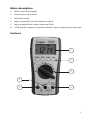
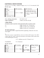
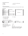
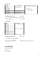
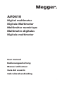
mM
AVO410
Digital multimeter
Digitale Multimeter
Multimèter numérique
Multímetro digitales
Digitale multimeter
User manual
Bedienungsanleitung
Manuel utilisateur
Guía del usuario
Gebruikershandleiding
1
G
SAFETY WARNINGS
Safety warnings must be read and understood before instrument is used.
The following safety information must be observed to insure maximum
personal safety during the operation of this meter:
■ Do
■
not use in wet environments.
Measurements beyond the maximum selected range must not be attempted.
■ Extreme
care must be taken when measuring above 50 V, especially on live bus-bars.
To measure voltage, the instrument must not be switched to a current or resistance range, or to the diode check or buzzer position.
■
■ Circuits
must be de-energised and isolated before carrying out resistance tests.
The rotary selector switch must only be turned after removing test connections.
■
All external voltages must be disconnected from the instrument before removing the battery.
■
■ Test
leads and prods must be in good order, clean, and with no broken or cracked insulation.
UK Safety Authorities recommend the use of fused test leads when measuring voltage on high energy systems.
■
■
Replacement fuses must be of the correct type and rating.
■
The instrument must not be used if any part of it is damaged.
Check for correct instrument operation by testing a known voltage before and after use. Do not use if misleading results are obtained.
■
■ Warnings
and precautions must be read and understood before an instrument is used.They must be observed during the operation of this instrument.
Note
This instrument must only be used by suitably trained and competent persons
2
Contents
Safety warnings............................................................................................. 2
Symbols used on instrument......................................................................... 3
Introduction.................................................................................................. 4
Operation...................................................................................................... 5
Specifications.............................................................................................. 10
Manual de l’utilisateur ................................................................................ 16
Bedienungsanleitung .................................................................................. 30
Manual del usuario ..................................................................................... 44
Gebruikershandleiging................................................................................ 56
Symbols used on the instrument are:
F Caution: risk of electric shock
G Caution: refer to accompanying notes
t Equipment protected throughout by Double Insulation (Class II)
c Equipment complies with current EU directives.
END OF LIFE DISPOSAL
The crossed out wheeled bin placed on the Megger products is a
reminder not to dispose of the product at the end of its product life
with general waste.
Megger is registered in the UK as a Producer of Electrical and Electronic
Equipment.The Registration number is WEE/HE0146QT.
BATTERIES
Should the display fail to illuminate then change the battery. For the purpose of
end of life disposal and battery replacement, removing the two screws on the
base of the unit accesses the battery.
The crossed out wheeled bin placed on the battery is a reminder not to dispose
of it with general waste at the end of its life.
This product contains 1 x PP3 / 6F22 alkaline battery.
Do not use rechargeable batteries.
The battery fitted in this instrument is classified as a Portable Battery and
should be disposed of in the UK in accordance with Local Authority
requirements.
For disposal of batteries in other parts of the EU contact your local distributor.
Megger is registered in the UK as a Producer of Batteries.The registration
number is BPRN00142.
3
Introduction
Thank you for purchasing the Megger AVO410 Digital Multimeter.
For your own safety and to get the maximum benefit from your instrument,
please ensure that you read and understand the safety warnings and
instructions before attempting to use the instrument.
The AVO410 is aimed at providing electricians with a rugged, easy to use
multimeter for field use. Functions include voltage, current and resistance; in
addition, there are extra functions that may also appeal to electrical and
electronic engineers. The instrument features automatic or manual selection of
ranges,True RMS readings and a CATIV 600 V safety rating.
Unpacking and inspection
Upon removing your new digital multimeter from its packing, you should have
the following items.
1. Digital multimeter.
2.Test lead set (one black, on red)
3. User manual.
4. Protective holster.
Symbols and annunciators
Continuity A
Low battery
▲
BAT Diode test
HOLD Data hold
AUTO Auto-ranging
AC Alternating current or voltage
DC Direct current or voltage
MAX/MIN Stores the highest or lowest measurement
JBacklight
V
Volts
A, mA,uA Current range
4
Meter description
1.
6000 counts LCD display.
2.
Push buttons for features
3.
Selection switch
4.
Input terminal for all other functions (Red)
5.
Input terminal for A current selection (Red)
6.
COM (Black) common or ground reference input terminal for all functions.
Features
1
2
3
6
5
4
5
Operation
AC VOLTAGE MEASUREMENTS
1. Set the function switch to the V AC position (AUTO,T-RMS and AC volts will appear on the display).
2. Insert the black test lead in the COM jack and the red test lead into the V jack.
3. Connect the test probe tips to the circuit under test.
4. Read the voltage on the display.
DC VOLTAGE MEASUREMENTS
1. Set the function switch to the V DC position (AUTO and DC volts will be appear on the display).
2. Insert the black test lead into the COM jack and the red test lead into the V jack.
3. Connect the test probe tips to the circuit under test. Be sure to observe the correct polarity (red lead to positive, black lead to negative)
4. Read the voltage on the display. If the polarity is reversed, the display will show (-) minus before the reading.
RESISTANCE (Ω) MEASUREMENTS
1. Set the function switch to the Ω position (AUTO and MΩ will appear on the display).
2. In addition, O.L will be displayed indicating an open circuit.
3. Insert the black test lead into the COM jack and the red test lead into the Ω jack.
4. Connect the test probe tips to the circuit under test.
5. According to measured value the reading will be in Ω, kΩ or MΩ.
Note: The AVO410 provides an open circuit voltage <-1.5 V to the circuit under
test which will cause transistor junctions to conduct so it is advisable to
disconnect the item to be tested from the circuit to obtain an accurate reading.
DIODE / CONTINUITY TESTS
WARNING: To avoid electric shock never test a diode or conduct a continuity
test on an energized circuit.
1. Set the function switch to the diode/continuity position. (The diode and V symbols will appear).
2. In addition, .OL will be displayed indicating an open circuit.
3. Insert the black test lead into the COM jack and the red test lead into the Ω jack.
6
4. For continuity connect the test probes to the cable or circuit to be tested. (Polarity is not important).
5. The AVO410 will emit a tone if continuity is below 500 Ω / .OL with no tone will indicate either open circuit or continuity above 500 Ω.
6. For diode testing connect the test probe tips to the diode or semiconductor junction and note the reading.
7. Reverse the probe polarity by switching probe position and note this reading.
8. The diode or junction can be evaluated as follows:
a. If one reading shows a value and the other reading shows .OL, the diode is good.
b. If both readings show .OL, the device is open circuit.
c. If both readings are very small or zero, the device is shorted.
DCµA MEASUREMENTS (6000 µA max.)
1. Set the function switch to the DCµA position. (AUTO and DCµA will be displayed).
2. Insert the black test lead into the COM jack and the red test lead into the µA jack.
3. Remove power from circuit under test, then open circuit at a convenient point where current is to be measured.
4. Connect the black test probe to the negative side of the circuit. Connect the red test probe to the positive side of the circuit.
5. Carefully apply the power
6. Read the measured on the display.
7. Remove supply before removing test leads and reconnecting circuit.
CAPACITANCE MEASUREMENTS
WARNING: To avoid damage to the instrument. Before testing, discharge the
capacitor/s to be tested.
1. Set the function switch to the capacitor position (AUTO and nF will be appear on the display).
2. Insert the black test lead into the COM jack and the red test lead into the capacitance jack.
3. Connect the test probe tips to the capacitor under test. Be sure to observe the correct polarity if the capacitor is an electrolytic / polarised type. Red to positive and black to negative.
4. Read the value on the display.
7
FREQUENCY MEASUREMENTS
1. Set the function switch to the Hz position (AUTO and Hz will appear on the display).
2. Insert the black test lead in the COM jack and the red test lead into the Hz jack.
3. Connect the test probe tips to the circuit under test.
4. Read the frequency on the display.
AC CURRENT MEASUREMENTS
1. Set the function switch to the AC A position. (AUTO,T-RMS and AC A will appear on the display).
2. Insert the black test lead into the COM jack and the red test lead into the A jack.
3. Remove power from circuit under test, then open circuit at a convenient point where current is to be measured.
4. Connect the black test probe to the negative side of the circuit. Connect the red test probe to the positive side of the circuit.
5. Carefully apply the power
6. Read the measured on the display.
7. Remove supply before removing test leads and reconnecting circuit.
DC CURRENT MEASUREMENTS
1. Set the function switch to the DC A position. (AUTO and DC A will appear on the display).
2. Insert the black test lead into the COM jack and the red test lead into the A jack.
3. Remove power from circuit under test, then open circuit at a convenient point where current is to be measured.
4. Connect the black test probe to the negative side of the circuit. Connect the red test probe to the positive side of the circuit.
5. Carefully apply the power
6. Read the measured on the display.
7. Remove supply before removing test leads and reconnecting circuit.
FEATURE BUTTONS
BACKLIGHT
The AVO410 has a backlit display for all the different functions which has an
auto off in 60 seconds.
8
MIN MAX
The MIN MAX function enables the user to display both a minimum and a
maximum measured reading.To activate, first select a function and make a
measurement. Press the MIN MAX button to store the maximum reading.
Should the value increase then the new value will be stored. Pressing the
MIN MAX button once more will switch the instrument display to minimum
reading.
Pressing the HOLD button while in MIN MAX mode will stop the AVO410 updating the maximum and minimum displayed reading. Holding down the MIN
MAX button for >1 sec. will switch the
function off.
HOLD
Press the HOLD button to freeze the reading on the display.The MIN MAX
function is unavailable when the Hold is active.
RS-232
With an optional USB adapter and software the AVO410 can be
utilised with a computer to provide a virtual multimeter mode.
RANGE
When any of the individual functions are first selected the unit will be in the
auto ranging mode.
Each successive press of the range button will enable the operator to manually
choose a required range.
AUTO POWER OFF / DISABLE
If the meter is idle for more than 10 minutes, the meter automatically turns the
display off. During this off time the last reading on the meter is stored.The
AVO410 can be restored by pressing any button.
To disable the power off function simultaneously hold down the MIN MAX,
RS232 and Range buttons and switch instrument to required function.
9
MAINTENANCE
To clean the instrument, do not immerse in water, periodically wipe the case
with a damp cloth and mild detergent. Dirt in the terminals may affect readings.
Remove the battery if the AVO410 is not to be used for a long period of time.
When the low battery symbol
appears on the display, replace the battery.
To replace battery remove instrument from black boot and unscrew two
screws on battery cover to reveal battery.
An internal user replaceable fuse can be accessed for replacement by unscrewing
the four deep recess screws. Carefully separate the two halves of the tester
taking care of battery lead. Use only the recommended replacement fuse
(10 A 500 V 32 mm).
SPECIFICATIONS
General Specifications
Display: 6000 counts updates 1.5/sec.
Polarity indication: Automatic, positive implied, negative indicated
Overrange indication: “OL” or “-OL”
Low battery indication: Displayed when the battery voltage drops below operating voltage
Auto power off: Approx 10 minutes
Operating ambient:
Non-condensing ≤10 °C, 11 °C ~ 30 °C (≤80% R.H)
31 °C ~ 40 °C (≤75% R.H), 41 °C ~ 50 °C (≤45% R.H)
Storage temperature: -20 ºC to 60 ºC, 0 to 80% R.H. when battery removed from meter
Temperature coefficient: 0.15 x (Spec.Acc’y) / ºC, <18 ºC or > 28 ºC
Power requirements: Standard 9V battery NEDA 1604, IEC6F22, JIS006P
Battery life: Alkaline 300 hours
Dimensions (W x H x D):
76 mm x 158 mm x 38 mm without
holster
Weight:
10
522 g
82 mm x 164 mm x 44 mm with holster
ELECTRICAL SPECIFICATIONS
Accuracy is ± (% reading + number of digits) at 23 ºC ±5 ºC, less than 80% R.H
DC/AC volts
Range
DC accuracy
AC accuracy
600.0 mV
6.000
60.00 V
± (0.5% + 2 digits)
600.0 V
DC 1000 V/AC 750 V
50 Hz/60 Hz sine wave
only for 600.0 mV range,
± (0.9% + 5 digits) 50 Hz
~ 500 Hz
*1
Over voltage protection:
DC 1000 V or AC
Input impedance:
10 MΩ // less than 100 pF
CMRR/NMRR
(Common mode rejection ration/normal mode rejection ratio)
VAC: CMRR >60 dB at DC, 50 Hz/60 Hz
VDC: CMRR >100 dB at DC, 50 Hz/60 Hz
NMRR >50 dB at DC, 50 Hz/60 Hz
AC conversion type:
AC conversions are AC coupled True RMS responding, calibrated to the sine
wave input.
*1
The basic accuracy is specified for a sine wave below 4000 counts. Over 4000
counts, add 0.6% to the accuracy. For non-sine waves below 2000 counts, refer
to the following for accuracy:
±1.5% addition error for C.F from1.4 to 3
Crest factor:
C.F. = Peak/rms
DC/AC current
Range
DC accuracy
600.0 µA
6000 µA
6.000 A
10.00 A
AC accuracy
N/A
± (1.0% + 2 digits)
±(1.5% +6 dgt)
50 Hz ~ 500 Hz
*1
Voltage burden
<4 mV/µA
2 V max
11
Overload protection
A input:
10 A (500 V) fast blow fuse
µA input:
600 V rms
*1
AC conversion type:
Conversion type and additional specification are the same as DC/AC voltage
Resistance
Range
Accuracy
Overload protection
600.0 Ω *2
6.000 KΩ
60.00 KΩ
± (0.7% + 2 digits)
600 V rms
600.0 KΩ
6.000 MΩ
± (1.0% + 2 digits)
60.00 MΩ *1
± (1.5% + 2 digits)
Open circuit voltage:
-1.3 V approx.
*1 <100 digit rolling
*2 <10 digit rolling
Diode check and continuity
ResolutionAccuracy
10 mV
▲
Range
± (1.5% + digits*)
* For 0.4 V ~ 0.8 V
Max. test current:
1.5 mA
Max. open circuit voltage:
3V
Overload protection:
600 V rms
Continuity:
Built-in buzzer will sound when the resistance is less than 500 Ω approx.
Response time is 100 ms approx.
12
Frequency
Range
6000 Hz
60.00 KHz
**Sensitivity
Overload protection
100 mV rms
Frequency:
600.0 KHz
*
6.000 MHz
250 mV rms
60.00 MHz
1 V rms
Overload protection:
0.1% ±1 digit
600 V rms
* Less than 20 Hz, the sensitivity is 1.5 V rms
** Max. sensitivity:
<5 V ac rms
Capacitance
RangeAccuracy
6.000 nF
60.00 nF
600.0 nF
6.000 µF
± (1.9%) +8 digits)
60.00 µF
600.0 µF
6.00 mF*
Overload protection:
600 V rms
* <100 digit of reading rolling
Auto power off (APO):
If idle for more than 10 minutes
ACCESSORIES
Battery (installed)
Test leads
User manual
13
REPAIR AND WARRANTY
The instrument contains static sensitive devices, and care must be taken in
handling the printed circuit board. If an instrument’s protection has been
impaired it should not be used, but sent for repair by suitably trained and
qualified personnel.The protection is likely to be impaired if for example; it
shows visible damage; fails to perform the intended measurements; has been
subjected to prolonged storage under unfavourable conditions, or has been
subjected to severe transport stresses.
Note: Any unauthorised prior repair or adjustment will automatically
invalidate the warranty.
INSTRUMENT REPAIR AND SPARE PARTS
For service requirements for Megger instruments contact:
Megger Limited or Megger
Archcliffe Road Valley Forge Corporate Centre
Dover2621 Van Buren Avenue Kent CT17 9EN
Norristown PA 19403 England. U.S.A.
Tel: +44 (0) 1304 502 243 Tel: +1 610 676 8579
Fax: +44 (0) 1304 207 342
Fax: +1 610 676 8625
or an approved repair company.
Returning and Instrument for Repair
If it is necessary to return an instrument for repair, a Returns Authorisation
number must first be obtained by contacting one of the addresses shown.You
will be asked to provide key information, such as the instrument serial number
and fault reported when the number is issued.This will enable the Service
Department to prepare in advance for the receipt of your instrument, and to
provide the best possible service to you.
The Returns Authorisation number should be clearly marked on the outside
of the product packaging, and on any related correspondence.The instrument
should be sent, freight paid to the appropriate address. If appropriate a copies
of the original purchase invoice and of the packing note, should be sent
simultaneously by airmail to expedite clearance through customs.
For instruments requiring repair outside the warranty period a repair estimate
will be submitted to the sender, if required, before work on the instrument
commences.
14
Approved Repair Companies
A number of independent instrument repair companies have been authorised
for repair work on most Megger instruments, using genuine Megger spare
parts. A list of approved companies is available from the UK address shown.
15
M
Megger Limited
Archcliffe Road
Dover CT17 9EN
T: 01304 502101
F: 01304 207342
Megger
4271 Bronze Way,
Dallas, Texas 75237-1019 USA
T: 1-800-723-2861
F: 1-214-331-7399
Megger Valley Forge Corporate Centre
2621 Van Buren Avenue
Norristown, PA 19403 USA
T: 610 676 8500
F: 610-676-8610 (from the US 8610)
Megger SARL
23 rue Eugène Henaff
ZA du Buisson de la Couldre
78190 TRAPPES
France
Telephone
T: 01 30 16 08 90
F: 01 34 61 23 77
Megger GmbH
Obere Zeil 2
61440 Oberursel
Deutschland
T: 06171-92987-0
F: 06171-92987-19
Megger Pty Limited
Unit 1, 11-21 Underwood Road
Homebush
NSW 2140
T: +61 (0)2 9397 5900
F: +61 (0)2 9397 5911
Megger products are distributed in 146 countries worldwide.
The company reserves the right to change the specification or design without prior notice.
Megger is a registered trademark
Part No. AVO410_UG_V03 0313
www.megger.com
70