1
indigo powercore manual.book Page 1 Thursday, April 22, 2004 12:23 PM
!##%336)2536)245!,!.!,/'39.4(%3):%2
53%22%&%2%.#%-!.5!,).%.',)3(
indigo powercore manual.book Page 2 Thursday, April 22, 2004 12:23 PM
indigo powercore manual.book Page 3 Thursday, April 22, 2004 12:23 PM
!##%336)2536)245!,!.!,/'39.4(%3):%2
53%22%&%2%.#%-!.5!,).%.',)3(
indigo powercore manual.book Page 4 Thursday, April 22, 2004 12:23 PM
Copyright 2004 Access Music GmbH. All rights reserved.
Written by Ben Crosland.
This manual, as well as the software and hardware
described in it, is furnished under license and may
be used or copied only in accordance with the
terms of such license. The content of this manual is
furnished for informational use only, is subject to
change without notice and should not construed as
a commitment by Access Music GmbH. Access Music GmbH assumes no responsibility or liability for
any errors or inaccuracies that may appear in this
book.
Except as permitted by such license, no part of this
publication may be reproduced, stored in a retrieval
system, or transmitted in any form or by any means,
electronic, mechanical, recording, or otherwise
without the prior written permission of Access Music GmbH.
Virus is a trademark of Access Music GmbH. All
other trademarks contained herein are the property
of their respective owners. All features and specifications subject to change without notice.
Visit our website here: www.access-music.de
indigo powercore manual.book Page 5 Thursday, April 22, 2004 12:23 PM
Table of Contents
Welcome
Installation
Installing the VPC On Your Computer . 9
Instancing the VPC in Logic . . . . . . . . 10
Instancing the VPC in Cubase SX2 . . . 12
Patch Management
Total Recall . . . . . . . . . . . . . . . . . . . . . 15
Loading Patches . . . . . . . . . . . . . . . . . 15
Saving Patches . . . . . . . . . . . . . . . . . . 18
How To Install Your Own Patches . . . 19
Using Multiple Parts
Parts and DSPs . . . . . . . . . . . . . . . . . . 21
Adjusting Parameters . . . . . . . . . . . . . 22
Using Remote Controllers
Getting Started
An Introduction to Viral Synthesis. . . . 27
Oscillators . . . . . . . . . . . . . . . . . . . . . . 27
Mixer. . . . . . . . . . . . . . . . . . . . . . . . . . . 28
Filter . . . . . . . . . . . . . . . . . . . . . . . . . . . 28
Amplifier . . . . . . . . . . . . . . . . . . . . . . . . 29
Effects . . . . . . . . . . . . . . . . . . . . . . . . . 29
Modulation Matrix . . . . . . . . . . . . . . . . 29
Viewing Pages . . . . . . . . . . . . . . . . . . . 30
Easy Page
Parameters of the Easy Page. . . . . . . 34
The Osc Page
Osc 1 . . . . . . . . . . . . . . . . . . . . . . . . . .
Osc 2 . . . . . . . . . . . . . . . . . . . . . . . . . .
Osc 3 . . . . . . . . . . . . . . . . . . . . . . . . . .
Sub/Noise . . . . . . . . . . . . . . . . . . . . . .
Velocity Mod . . . . . . . . . . . . . . . . . . . .
Unison Mode. . . . . . . . . . . . . . . . . . . .
Mixer . . . . . . . . . . . . . . . . . . . . . . . . . .
38
39
42
43
43
45
46
The Filter/Env Page
Filter 1 . . . . . . . . . . . . . . . . . . . . . . . . .
Filter 2 . . . . . . . . . . . . . . . . . . . . . . . . .
Filter Envelope . . . . . . . . . . . . . . . . . .
Amplifier Envelope . . . . . . . . . . . . . . .
52
54
56
57
The LFO Page
LFO 1 . . . . . . . . . . . . . . . . . . . . . . . . . . 60
LFO 2 . . . . . . . . . . . . . . . . . . . . . . . . . . 63
LFO 3 . . . . . . . . . . . . . . . . . . . . . . . . . . 66
The FX-1 Page
Analog Boost . . . . . . . . . . . . . . . . . . . 70
Ring Mod. . . . . . . . . . . . . . . . . . . . . . . 70
Phaser . . . . . . . . . . . . . . . . . . . . . . . . . 70
VIRUS POWERCORE MANUAL
5
indigo powercore manual.book Page 6 Thursday, April 22, 2004 12:23 PM
Patch Distortion . . . . . . . . . . . . . . . . . .72
Chorus . . . . . . . . . . . . . . . . . . . . . . . . .72
Output . . . . . . . . . . . . . . . . . . . . . . . . . .73
Delay/Reverb . . . . . . . . . . . . . . . . . . . .74
Delay . . . . . . . . . . . . . . . . . . . . . . . . . . .76
Reverb. . . . . . . . . . . . . . . . . . . . . . . . . .77
The FX2/Global Page
Vocoder. . . . . . . . . . . . . . . . . . . . . . . . .80
Using the Audio Inputs. . . . . . . . . . . . .83
Envelope Follower . . . . . . . . . . . . . . . .84
Global . . . . . . . . . . . . . . . . . . . . . . . . . .85
Pitch . . . . . . . . . . . . . . . . . . . . . . . . . . .86
Pitch Wheel. . . . . . . . . . . . . . . . . . . . . .87
Patch Param . . . . . . . . . . . . . . . . . . . . .88
Keyboard . . . . . . . . . . . . . . . . . . . . . . .89
Arpeggiator . . . . . . . . . . . . . . . . . . . . . .90
The ModMatrix Page
Assign 1 . . . . . . . . . . . . . . . . . . . . . . . .94
Assign 2 . . . . . . . . . . . . . . . . . . . . . . . .94
Assign 3 . . . . . . . . . . . . . . . . . . . . . . . .95
Categories . . . . . . . . . . . . . . . . . . . . . .96
Customer support
Appendix
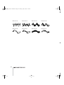
Oscillator and LFO waveforms . . . . . .99
Appendix
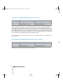
System Exclusive Data. . . . . . . . . . . .103
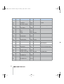
Parameters Description . . . . . . . . . . .105
Classes . . . . . . . . . . . . . . . . . . . . . . . .112
6
indigo powercore manual.book Page 7 Thursday, April 22, 2004 12:23 PM
Welcome
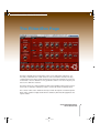
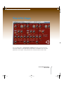
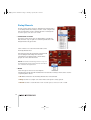
Thank you for purchasing the Access Virus PowerCore (VPC). You now have amongst
your sonic arsenal a truly amazing synthesizer, fully equipped to infect your music with
some serious attitude! Rest assured that no compromises have been made here Access have equipped the Virus PowerCore with a sound engine that is identical in
every way to that of the now legendary Virus series. The oscillator section features 3
main oscillators, each capable of generating one of 66 waveforms, plus a sub-oscillator
for those extra-deep basses. Add to this a noise generator, oscillator sync, FM and ring
modulation capabilties and you have a tone-palette that is truly vast! What’s more, up to
16 voices can be achieved on each DSP, meaning those of you lucky enough to own
four PowerCores and the full license for your Virus PowerCore can infect their tracks
with up to 256 simultaneous voices of Virus phattitude!
The filters in the Virus PowerCore are second to none and with the flexible routing
options and a wide variety of saturation modes, all manner of filter characteristics can
be achieved. Anything from the smooth, warm tones associated with traditional analog
synthesizers to the most gut-wrenching, teeth-rattling, speaker-shredding sonic terror is
possible!
The Virus PowerCore also sports a powerful effects section, featuring effects such as
chorus, phaser, distortion, delay and reverb as well as input ring modulation and a vocoder. Furthermore, with its flexible audio inputs, the Virus becomes an incredibly powerful effects processor. Any audio signal can be routed through both the filters and effects,
so none of your audio tracks will be immune to infection!
One feature which you are bound to appreciate immediately is Access’ acclaimed
Adaptive Parameter Smoothing technology. Unlike many other soft-synths, where every
parameter change is accompanied by obvious ‘stepping’ through the values, every
adjustment you make will happen seamlessly and in realtime, meaning that live tweaking is now a truly joyful experience.
Loading and saving patches has never been easier, thanks to the advanced patch management system in the Virus PowerCore. As soon as the Virus plug-in is enabled, it
scans the PowerCore folder on your hard-drive and loads all of the patches it finds there
into RAM. From there it organises them into heirarchical menus and categories, so you
VIRUS POWERCORE MANUAL
7
indigo powercore manual.book Page 8 Thursday, April 22, 2004 12:23 PM
can get straight to the patches you want. All patches used in the current session are stored in
the Recently Used folder, and over time, your most commonly-used patches will be automatically stored to the Favourites folder for instant recall.
NOTE: The Virus PowerCore is 100% compatible with the majority of patches available for
the Virus series, of which there are thousands available for free download at www.accessmusic.de
8
indigo powercore manual.book Page 9 Thursday, April 22, 2004 12:23 PM
Installation
Installing the VPC On Your Computer
> INSTALLING ON A PC/WIN32
Run the installer program ‘Virus PowerCore Installer.exe’ included in the download.
The installer will copy both the Virus Powercore.dll and the Virus Input.dll into the VstPlugIns folder of your sequencer/host software. Virus Powercore.dll is the main synthesizer plugin, and Virus Input.dll is the side-chain effect plugin. (If the installer selects the
wrong host software, just locate the .dll files and copy/paste them into the VstPlugIns\POWERCORE folder of your preferred host software.)
A folder will be created in the location:
C:\Documents and Settings\(your username)\My Documents\Access Music\Virus Powercore.
Into this folder you should copy any .mid files you have which contain Virus patch libraries. Check the download section of www.access-music.de for a large selection of freely
downloadable patches. The Virus PowerCore is compatible with the Virus hardware
synthesizers, so any existing Virus patches are suitable.
> INSTALLING ON A MAC
Run the installer program ‘Virus PowerCore Installer’ included in the download.
The installer will copy the Virus Powercore and Virus Powercore Input plugin to
/Library/Audio/Plug-Ins/VST/POWERCORE.
A folder will be created in the location ~/Library/Application Support/Access Music/
Virus Powercore. Into this folder you should copy any .mid files you have which contain
Virus patch libraries. Check the download section of www.access-music.de for a large
selection of freely downloadable patches. The Virus PowerCore is compatible with the
Virus hardware synthesizers, so any existing Virus patches are suitable.
VIRUS POWERCORE MANUAL
INSTALLATION
9
indigo powercore manual.book Page 10 Thursday, April 22, 2004 12:23 PM
> AUDIO UNITS
To use the Virus PowerCore as an Audio Unit, you need to run the TCAU Audio Unit wrapper
after you have run the Virus installer. Installing the PowerCore driver also installs the TCAU
wrapper although it’s recommended to ckeck the TC website for updates frquently.
Instancing the VPC in Logic
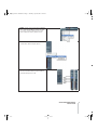
STEP1: Create a new Audio Instrument in the
arrange window
STEP2: Now select the Virus PowerCore by
opening the instrument popup menu within
the audio object. For maximum flexibility
choose "Multi Channel" which enables you to
route the four parts of the Virus to individual
outputs and thus treat them individually with
additional effects.
10
indigo powercore manual.book Page 11 Thursday, April 22, 2004 12:23 PM
STEP3: To gain access to the Virus’ individual
outs, create an Aux Object. Please note that
you need to create an Aux object for every
stereo output you wish to gain access to.
STEP4: Now select the Virus' individual outs
from the Aux channel's Input options
STEP5: Now open up the environment, select
the Virus instrument and change the MIDI in
channel ("Cha") from 1 to All.
VIRUS POWERCORE MANUAL
INSTALLATION
11
indigo powercore manual.book Page 12 Thursday, April 22, 2004 12:23 PM
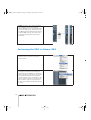
STEP6: The Virus is up to 4 part multi timbal
for each DSP used. The four multiparts
receive MIDI data on the corresponding channels 1-4. To easily access all four parts, create
four MIDI instruments within the environment,
assign the MIDI channels 1,2,3 and 4 to the
instruments and cable them into the Virus
Instrument.
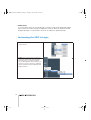
Instancing the VPC in Cubase SX2
STEP1: Select "VST Instruments" from the
"Devices" menu to show the "VST Instruments" window.
STEP2: In the "VST Instruments window", find
an empty VST Instrument slot. Empty VST
Instrument slots are labelled "no instrument".
Click on the label "no instrument" to open the
VST Instrument Selection menu and select
"Virus PowerCore" in the "Access Music" submenu to create an instance of the Virus PowerCore. After a couple of seconds, the Virus
PowerCore is initialized and its editor window
is shown.
12
indigo powercore manual.book Page 13 Thursday, April 22, 2004 12:23 PM
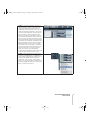
STEP3: In the Arrange Window, the Virus is
represented by a number of tracks that are
created automatically by Cubase SX. The
folder track "VST Instruments" shows all currently running VST Instruments; in this case it
only shows the folder track "Virus Powercore"
which contains a number of tracks to automate various aspects of the Virus Powercore.
The topmost track labelled "Virus Powercore"
allows you to automate the parameters of the
Virus itself while the other four tracks labelled
"Virus Out1" to "Virus Out4" automate the VST
Mixer parameters of the four stereo outputs of
the Virus PowerCore. If you are confused by
these tracks, just click the little "-" symbol to
the left of the "VST Instruments" track to collapse the whole tree. You can ignore these
tracks for now but you should read the
Cubase SX documentation later to learn what
to do with these tracks if you are unsure.
STEP4: Create a MIDI Track to play the Virus
PowerCore via MIDI and to record MIDI messages that are played back by Cubase SX. To
do that, select "MIDI" from the sub-menu
"Add Track" in the "Project" menu. Alternatively, you can open the Track context menu in
the track list (Mac: Ctrl+Click, PC: right mouse
button click) as shown below.
VIRUS POWERCORE MANUAL
INSTALLATION
13
indigo powercore manual.book Page 14 Thursday, April 22, 2004 12:23 PM
STEP5: Select "Virus PowerCore" from the
"out" menu in the track inspector to route the
MIDI output of the track to the Virus PowerCore.
STEP6: Select MIDI channel "1" from the
"chn" menu in the track inspector to play Part
1 of the Virus PowerCore.
Now you can play the Virus Powercore via
MIDI and record on the created MIDI track.
You can create further MIDI tracks and assign
them to any of the four Parts of the Virus by
selecting the respective MIDI channel from the
"chn" menu.
14
indigo powercore manual.book Page 15 Thursday, April 22, 2004 12:23 PM
Patch Management
Total Recall
The Virus PowerCore has a sophisticated Patch Management system, designed to
make browsing and sourcing patches easier than ever before. As soon as you instance
the Virus PowerCore in your sequencer, it will automatically scan the Virus PowerCore
folder on your computer’s hard-drive for any .mid files containing banks of Virus
patches and store them in RAM for instant recall. Patches are then sorted alphabetically
within each bank, and organised into Categories, to make browsing a breeze.
> THE POWERCORE FOLDER
This is where you store all your Virus PowerCore patches. If you are running Windows it
is located in “My Documents\Access Music\PowerCore”. If you are running Mac OS it is
located in ~/Library/Application Support/Access Music/PowerCore.
NOTE: If you have a large number of banks you may wish to create sub-folders within
the PowerCore folder - these will also be scanned automatically, and appear within the
heirarchical menu structure.
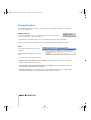
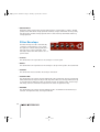
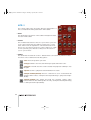
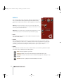
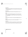
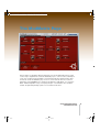
Loading Patches
To load a patch click on the LOAD tab at the
top right of the screen. The following dropdown menu will appear:
· Position the mouse pointer on ‘Patches’
and the next level will appear listing all the
available banks.
· Position the mouse pointer on the bank you
wish to browse, and a list of all the patches
contained in this bank will appear.
VIRUS POWERCORE MANUAL
PATCH MANAGEMENT
15
indigo powercore manual.book Page 16 Thursday, April 22, 2004 12:23 PM
· Select the patch you wish to audition with a single mouse click.
NOTE: If the selected bank contains too many entries to display all at once, you will see a little
arrow at the bottom of the list. Click on this arrow to scroll through the rest of the entries.
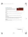
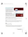
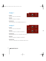
> CATEGORIES
The Virus PowerCore will scan all the patches it finds and
organise them according to their category settings. This
means if you need a bass sound, you need only look in the
‘Bass’ category if you wish. The patches are displayed alphabetically with name of the bank from which they were sourced.
NOTE: If the selected category contains too many entries to
display all at once, you will see a little arrow at the bottom of
the list. Click on this arrow to scroll through the rest of the
entries.
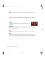
> RECENTLY USED
Patches which have been used in the current
session are stored in the Recently Used menu,
so you needn’t go searching through all the
banks again to find that great lead sound you
had half an hour ago. Banks are displayed
according to the date of the session in which
they were created ie:
NOTE: Note that patches that are accessed via the browse buttons will not be added to the
Recently Used menu automatically. However, if they are being used in the song when it is
saved, they will then be added
> Clear this list: Use this to clear all entries from the Recently Used list.
16
indigo powercore manual.book Page 17 Thursday, April 22, 2004 12:23 PM
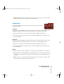
> FAVOURITES
The Virus PowerCore will automatically compile your most commonly
used patches in the Favourites folder. It works by assigning ‘points’
to the patches you have used in your projects, for instance:
Patch is used in a project (host has saved the settings to a song) = 5 points
Patch was saved (using the plug-in’s Save menu) = 2 points
Up to 100 favourites can be stored internally, with the top twenty visible to the user. As soon
as one patch drops out off the list (by scoring less points than No.100) the value of all remaining patches will be reduced so that the lowest scoring patch has only one point. This ensures
that ‘new’ patches stand a chance of being included in the list.
> Clear this list: Use this to clear all entries from the Favourites list.
> BROWSING PATCHES
At the top right hand corner of the Virus PowerCore window, you will see
the name of the currently selected patch with two arrows (up/down) alongside.
By clicking on the browsing arrows, you can easily audition every patch in the currently
selected bank. You may also use this method to browse the currently selected Category
menu.
NOTE: The browsing arrows will only be available once you have selected a patch from one
of the menus.
> RESCAN PATCH FOLDER
Click on ‘Rescan patch folder’ if you have added any new .mid files containing Virus patches
to the PowerCore folder since instancing the Virus PowerCore. The new banks will now be
displayed.
VIRUS POWERCORE MANUAL
PATCH MANAGEMENT
17
indigo powercore manual.book Page 18 Thursday, April 22, 2004 12:23 PM
Saving Patches
If you make any changes to a patch, or indeed create a completely new patch, you may wish
to save it for future use.
> NAMING A PATCH
It is always advisable to choose an appropriate name for a new patch, so
you can locate it more easily in the future.
To change the current patch name, click on the name pane at the top of the window.
Type in the new name. Press Return on your computer keyboard to enter the new name.
> SAVE
To save the current patch, click on the
Save tab.
The Save menu will appear (see screenshot).
You can now choose from three options:
> Replace “(old patchname) xxx” in “xxx Bank”: The original version of the current patch
will be overwritten by the new version.
> Save as new entry “(new patchname) xxx” in “xxx Bank”: The newly edited patch will
be appended to the currently selected bank.
> Patches: Alternatively you can select ‘Patches’ which will give you the option of appending
the newly edited patch to any of the banks in the PowerCore folder ie
18
indigo powercore manual.book Page 19 Thursday, April 22, 2004 12:23 PM
How To Install Your Own Patches
Firstly, you will need to download some new soundsets. There are several available for free at
www.access-music.de, between them covering a wide variety of musical tastes.
Once you have downloaded some soundsets, locate the .mid versions and copy/paste them
to the Virus Powercore folder. On a Windows PC, this will be located in: C:\Documents and
Settings\(your username)\My Documents\Access Music\Virus Powercore. On a Mac, it will be
located in: ~/Library/Application Support/Access Music/Virus Powercore.
NOTE: It is important to realise that only sounds saved in .mid format will be recognised by
the Virus PowerCore. Only SMF format 0 is supported
Next time the you instance the Virus PowerCore, you will find the new soundbanks listed in
the Patches menu.
You may wish to organise the banks into folders for easier browsing. If you do not wish a
bank to be loaded every time you instance the Virus PowerCore, simply delete it from the
Virus Powercore folder, or cut/paste it into another location.
VIRUS POWERCORE MANUAL
PATCH MANAGEMENT
19
indigo powercore manual.book Page 20 Thursday, April 22, 2004 12:23 PM
20
indigo powercore manual.book Page 21 Thursday, April 22, 2004 12:23 PM
Using Multiple Parts
Parts and DSPs
The TC PowerCore has four DSP processors which it uses to process the various plugins including Virus PowerCore. The Base License package allows one of these DSPs
to be used for the Virus, which can be split up into four ‘Parts’ - each with it’s own voice
and individual output routing.
With the Base License, you can only use one Virus simultaneously, if you find that you
really need to use more than one instance at a time, you should consider purchasing the
Extended License.
The Part/DSP box at the top of the plugin window displays the current part and the DSP
it is using i.e.
To choose a different part, click on the box and select the desired part from the dropdown list.
Each part corresponds to it’s equivalent MIDI channel i.e. Part 1 = MIDI channel 1, Part
2 = MIDI channel 2. Please refer to your sequencer manual for instructions on how to
address different MIDI channels on the same audio instrument.
With the Extended License package,
then you can utilise as many DSPs as
there are in your PowerCore system.
Each time you instance the Virus PowerCore on a new audio instrument,
another DSP is used.
VIRUS POWERCORE MANUAL
USING MULTIPLE PARTS
21
indigo powercore manual.book Page 22 Thursday, April 22, 2004 12:23 PM
> GLOBAL EFFECTS
Most of the effects in the Virus PowerCore are specific to each part, but the delay/reverb
effect is global i.e. all parts using the same DSP use the one delay/reverb effect. Please refer
to the Delay/Reverb section of the FX1 Page section of the manual for more specific instructions. If you wish to use more than one delay/reverb effect simultaneously, you must instance
the Virus PowerCore on another audio instrument (Extended License only).
Adjusting Parameters
The majority of Virus PowerCore controls can be adjusted by either dragging a knob, clicking
on a button or typing in a specific value.
The majority of parameters have a value range of 0 - 127. The value increases as you rotate
the knob clockwise.
There are some knobs that are bipolar. In this case the value range is -64 to 0 to +63. Centre
position (12 o'clock) is zero. Rotate the knob in an anti-clockwise direction to specify values
down to -64. Rotate clockwise to specify values up to +63.
> ADJUSTING KNOBS
Drag the knob either vertically or horizontally. (Some host software may also allow you to use
the mouse-wheel to adjust knobs.)
> TYPING IN VALUES
The majority of parameters also have a text box, which displays the current value. This can be
edited via the computer keyboard:
> TYPING A VALUE INTO A TEXT BOX
Click on the text box and then type in the desired value. If the parameter is bipolar and you
wish to specify a negative value, you must type a minus sign in front of the numbers.
To input the value without leaving the selected text box, press Enter on your numeric keypad.
To input the value and exit keyboard editing mode, press Return (Mac) or Return on the Alpha
keypad (Windows PC).
22
indigo powercore manual.book Page 23 Thursday, April 22, 2004 12:23 PM
NOTE: Many parameters in the Virus PowerCore are inter-dependent, meaning that adjusting
certain parameters may or may not have an audible effect, depending on the value of another.
For instance if Filter Balance is set to -64, only filter1 is audible; consequently adjustments to
filter 2 parameters will be inaudible.
VIRUS POWERCORE MANUAL
USING MULTIPLE PARTS
23
indigo powercore manual.book Page 24 Thursday, April 22, 2004 12:23 PM
24
indigo powercore manual.book Page 25 Thursday, April 22, 2004 12:23 PM
Using Remote Controllers
If you prefer you can choose to use an external controller to adjust the parameters of
the Virus PowerCore. Ideally this will be a hardware Virus, as all of the controllers will be
automatically mapped to their equivalent in the Virus PowerCore, but you could also
use a third-party remote controller or hardware synthesizer.
> USING A VIRUS SYNTHESIZER AS A REMOTE CONTROL DEVICE
Make sure that the MIDI OUT of the Virus is connected to the MIDI IN of your PC MIDI
interface. On the external Virus, set SYSTEM>MIDI>Panel to Int+Midi or Midi. This tells
the Virus to send controller data to the MIDI OUT port. Now set SYSTEM>MIDI CONTROL>LoPage to’ Contr’ and MIDI CONTROL> HiPage to PolyPrs.
Check that when you move a knob on the Virus or indeed adjust any parameter in the
edit menus that the equivalent parameter in the Virus PowerCore is updated accordingly.
NOTE: Please note that in certain sequencer hosts some parameters, such as Channel
Volume and Panorama will be intercepted by the audio instrument channel. In this case,
you will not be able to adjust these parameters by remote.
> USING A THIRD-PARTY DEVICE AS A REMOTE CONTROL
Please refer to the instruction manual of the third-party device for instructions on how to
configure it to send the appropriate control data. For a list of the controller numbers
associated with the various parameters in the Virus PowerCore, please refer to the
Appendix.
> USING YOUR SEQUENCER TO AUTOMATE THE VIRUS POWERCORE
Most sequencers allow you to automate the parameters of VST instruments. For
instructions on how to do this in your chosen sequencer, please refer to the instruction
manual that was included with your software. For a list of the controller numbers associated with the various parameters in the Virus PowerCore, please refer to the Appendix.
VIRUS POWERCORE MANUAL
USING REMOTE CONTROLLERS
25
indigo powercore manual.book Page 26 Thursday, April 22, 2004 12:23 PM
26
indigo powercore manual.book Page 27 Thursday, April 22, 2004 12:23 PM
Getting Started
An Introduction to Viral Synthesis
For the benefit of synthesis newbies, we will first discuss some of the basic concepts to
help you get an idea of what this is all about. The Virus PowerCore is based on 'subtractive' synthesis, which means that the sound begins life in the oscillator section as harmonically rich as it's going to get, then certain elements are removed via the filter
section and what's left is sculpted into the desired shape by the amplifier section. Of
course the Virus PowerCore is a lot more complex than this! What follows is an overview
of the main stages that constitute any Virus sound or 'patch'.
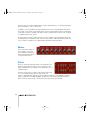
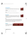
Oscillators
This is where life begins for a Virus PowerCore
sound. An oscillator generates a basic waveform, which, if left untreated, will sound as a
continuous tone for as long as a key is held.
Different waveforms contain different amounts of harmonics - it's these that give the
waveform it's timbre, or tonal character. For instance:
> Saw: Saw waveforms contain both odd and even harmonics, resulting in a very bright
and harsh tone.
> Pulse: Pulse waveforms (also known as a square wave) contains only the odd harmonics, which results in a bright, but somewhat 'hollow' tone.
> Sine: Sine waveforms contain no harmonics at all, only the fundamental, which is
what we refer to when we talk about the pitch of a note. Consequently, a sine wave
has a very pure timbre.
The 3 main oscillators in the Virus PowerCore are capable of generating all these,
including 63 additional spectral waves of all sorts of shapes and timbres.
VIRUS POWERCORE MANUAL
GETTING STARTED
27
indigo powercore manual.book Page 28 Thursday, April 22, 2004 12:23 PM
The Virus also has a sub-oscillator, which is used to add extra bass to a sound by tracking the
pitch of oscillator 1, only 1 octave lower.
In addition to the 3 oscillators and sub-oscillator, there is also a noise generator. This generates ‘white’ noise, which sounds rather like the noise a television makes when you unplug the
aerial. This is useful for creating snare drum sounds, sound FX such as wind or surf, or simply
for adding warmth to the sound.
As if this wasn't enough, the Virus PowerCore is also capable of ring modulation (ring mod)
and FM (frequency modulation), both of which can be used to add extra harmonics and overtones, useful for creating more complex timbres like bells and electric pianos.
Mixer
This is where the outputs of
the oscillators, noise, and
ring modulator are balanced
before the resulting mixture is
sent to the filter section.
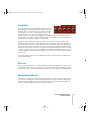
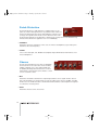
Filter
This is an extremely important stage of any subtractive synthesizer, and the Virus PowerCore is no exception to this
with it’s dual filters, each of which can be assigned to one of
4 different types.
A filter is used to remove certain components (frequencies)
of a sound, whilst allowing others to pass freely. For
instance, a lowpass filter will remove all the frequencies above a user-definable 'cutoff' frequency, whilst all those below will pass - geddit? The cutoff can be adjusted in realtime,
which results in a 'filter sweep' - the life-blood of many famous synth sounds.
28
indigo powercore manual.book Page 29 Thursday, April 22, 2004 12:23 PM
Amplifier
Once the signal has been suitably filtered, it then passes to
the amplifier to be shaped by the amp envelope. The way
that the volume of a sound changes over time is crucial to
our perception of it, and so just like the filter, this is a very
important stage of any synth sound. Believe it or not, on
certain old electronic organs, the only difference between the piano and trombone presets
was the shape of their amp envelopes!! (Bear in mind of course that it took a certain degree of
imagination to hear either as a piano or a trombone!)
A typical 4-stage amplitude envelope forces the sound to follow a specific volume curve
through the following stages - Attack, Decay, Sustain, and Release, with Attack determining
the time it takes for the note to reach full volume once a key is pressed, Decay determining
the rate at which it falls to the level at which the note will Sustain, and Release being the time
it takes the sound to decay to silence once the key is released. The Virus PowerCore actually
contains a 5-stage envelope, due to the addition of a Sustain Time parameter. This is used to
create an additional crescendo (volume swell) or decrescendo once the note has reached the
sustain level.
Note that the filter section also has a dedicated envelope for dynamically controlling the cutoff in a similar fashion.
Effects
Once the sound has been successfully mangled by the filters and amplifier, it then gets sent
to the Effects section. Here you can choose to colour the sound with several different (simultaneous) effect types, including Analog Boost, Distortion, Chorus, Phaser, and Delay/Reverb.
Modulation Matrix
Last, but by no means last as it happens, is the mod matrix. This is a very powerful tool that
you can use to dynamically control several parameters at once via a number of different control sources. The available control sources include LFO's, (see below) envelopes, MIDI note
velocity , modwheel and pitch bend as well as several others.
VIRUS POWERCORE MANUAL
GETTING STARTED
29
indigo powercore manual.book Page 30 Thursday, April 22, 2004 12:23 PM
NOTE: LFO is an abbreviation of Low Frequency Oscillator. Whereas the Virus PowerCore's
main oscillators generate frequencies high enough to be in the audio spectrum, the LFOs
generate much slower oscillations, which are very useful for modulating any of the parameters
in the both the synthesis section and the effects section. There are 3 LFOs in the Virus PowerCore.
The mod matrix itself is used to route the outputs of 3 control ‘sources’ to six ‘destination’
parameters.
There are also 10 pre-defined parameters which can be controlled by velocity (how hard you
press the key on a touch-sensitive keyboard).
Added together, this means a total of 29 parameters can be controlled simultaneously by up
to 7 modulation sources, which allows for a great deal of movement, interest and expression
within a single sound.
So hopefully you now have a general overview of the way the Virus PowerCore works, it's
time to look in more detail at how to achieve all this sonic naughtiness…
Viewing Pages
To make things easier, the controls of the Virus
PowerCore have been organised into seven different pages. To view a particular page, click
on the corresponding name in the upper left of the Indigo pane.
> EASY
The Easy Page contains controls for the most commonly edited parameters, i.e. filter cutoff,
resonance, amp attack, FX Send etc.
> OSC
The Osc Page contains the controls for the oscillators section, including ring mod, FM and
noise. The controls for the mixer section are also located on this page.
> FILTERS/ENV
The Filters/Env Page contains the controls for the filter section and both of the envelope generators.
30
indigo powercore manual.book Page 31 Thursday, April 22, 2004 12:23 PM
> LFO
The LFO Page contains the controls for the 3 low frequency oscillators (LFOs).
> FX-1
The FX-1 Page contains the controls for Analog Boost, Input RingMod, Phaser, Patch Distortion, Chorus and Delay/Reverb effects.
> FX-2/GLOBAL
The FX-2 Page contains the controls for the Vocoder, Input, Envelope Follower, and several
global settings such as Master Tune, Pitch Wheel, Unison Mode, etc.
> MODMATRIX
The Mod Matrix Page contains the controls for assigning all of the modulation sources and
destinations and their respective amounts.
VIRUS POWERCORE MANUAL
GETTING STARTED
31
indigo powercore manual.book Page 32 Thursday, April 22, 2004 12:23 PM
32
indigo powercore manual.book Page 33 Thursday, April 22, 2004 12:23 PM
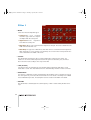
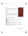
Easy Page
Here you will find a selection of controls for the most commonly edited parameters in
the Virus PowerCore. If you just want to tweak an existing patch without getting into it
too deeply, then this is the page for you.
VIRUS POWERCORE MANUAL
EASY PAGE
33
indigo powercore manual.book Page 34 Thursday, April 22, 2004 12:23 PM
Parameters of the Easy Page
> CUTOFF
This adjusts the cutoff frequency of both filters. The result will vary depending on the currently
selected filter modes.
> RESONANCE
This adjusts the amount of resonance (Q) for both filters. This determines how much those
frequencies near the cutoff frequencies will be emphasised, so the result will depend largely
cutoff frequency of both filters. Those who want to make their PowerCore squeal like a pig
need look no further.
> CHORUS MIX
Adjusts the balance between the dry signal and the chorus effect.
> PHASER MIX
Adjusts the balance between the dry signal and the phaser effect.
> SEND
Adjusts the balance between the dry signal and the delay/reverb effect.
> OSC VOLUME
Adjusts the volume of the combined outputs of the 3 oscillators and the sub-oscillator. Turning the knob past 12 o'clock position will increase the level of filter 1 saturation (if selected).
This controller has no effect on the volume of the noise generator or the ring modulator, both
of which have independent volume controls (Osc Page).
> SUB VOLUME
An independent volume control for the sub-oscillator. This is a very simple oscillator, which
always tracks the pitch of oscillator 1, but 1 octave lower. Use this to add more bass to a
sound.
> RING MODULATOR
Adjusts the volume of the ring modulator (see Osc Page).
34
indigo powercore manual.book Page 35 Thursday, April 22, 2004 12:23 PM
> AMP ATTACK
Adjusts the time it takes for the sound to reach maximum volume. At zero, the sound has
immediate impact, at higher values it will fade in gradually.
> AMP DECAY
This adjusts the time it takes for the sound to fall from maximum volume to the sustain level
(see Filters/Env Page).
VIRUS POWERCORE MANUAL
EASY PAGE
35
indigo powercore manual.book Page 36 Thursday, April 22, 2004 12:23 PM
36
indigo powercore manual.book Page 37 Thursday, April 22, 2004 12:23 PM
The Osc Page
The Osc Page is the birthplace of any Virus PowerCore patch. Here you will find the
controls for adjusting the 3 main oscillators, the sub-oscillator, the noise generator, ring
modulator and FM.
VIRUS POWERCORE MANUAL
THE OSC PAGE
37
indigo powercore manual.book Page 38 Thursday, April 22, 2004 12:23 PM
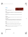
Osc 1
This is where you will find the controls for adjusting oscillator 1.
> SHAPE
This defines the shape of the waveform generated
by osc 1. When set to 0, the waveform will be
whatever is selected with the Wave Select knob.
Moving the knob in a clockwise direction will result
in a gradual transition to a pure saw wave at value
64 (default). As you continue to increase the value above 64, a square wave will be gradually
mixed in with the saw until, at a value of 127, a pure square wave is achieved.
> WAVE SELECT
The Wave Select knob allows you to choose from one of 64 waveshapes, including sine, triangle and 62 additional spectral waves. This parameter has no effect unless the value of
osc 1 SHAPE is between of 0 – 63.If you just want the pure waveform, set osc 1 Shape to 0.
If you would like to see a graphical representation of these waveforms, see the Appendix.
> PW
This determines the width of the pulses in a square wave, or the pulse width. At a setting of 0,
the wave is completely square – the pulse has 50% of the wave cycle. As you increase the
value, the pulses become thinner until, at a value of 127, they have 0% of the wave cycle,
resulting in silence.
> SEMITONE
This determines the pitch for osc 1, and is adjustable in semitone intervals. The default setting is 0, at which middle C will sound like middle C, but you have the option of transposing
osc 1 anywhere within a 4-octave range above or below this point.
> KEY FOLLOW
This determines how MIDI note number affects the pitch of osc 1. At the default setting of
+32, playing an ascending chromatic scale (play every key in sequence, including the black
keys) will cause the pitch of osc 1 to rise in semitone intervals. At a setting of +63, playing the
38
indigo powercore manual.book Page 39 Thursday, April 22, 2004 12:23 PM
same scale will cause the pitch to rise in whole tone intervals. A setting of 0 results in every
key sounding at the same pitch, and minus values will make osc 1 descend in pitch as you
play up the keyboard (useful for left-handed players ;-)
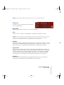
Osc 2
This is where you will find the controls for adjusting
oscillator 2. Many parameters are identical in function to their counterparts in osc1.
> SHAPE
This defines the shape of the waveform generated by
osc 2. When set to 0, the waveform will be whatever
is selected with the Wave Select knob. Moving the
knob in a clockwise direction will result in a gradual
transition to a pure saw wave at value 64 (default). As you continue to increase the value
above 64, a square wave will be gradually mixed in with the saw until, at a value of 127, a
pure square wave is achieved.
> WAVE SELECT
The Wave Select knob allows you to choose from one of 64 waveshapes, including sine, triangle and 62 additional spectral waves. This parameter has no effect unless the value of
osc 2 Shape is between of 0 – 63.If you just want the pure waveform, set osc 1 Shape to 0.
> PW
This determines the width of the pulses in a square wave, or the pulse width. At a setting of 0,
the wave is completely square – the pulse has 50% of the wave cycle. As you increase the
value, the pulses become thinner until, at a value of 127, they have 0% of the wave cycle,
resulting in silence.
> SEMITONE
This determines the pitch for osc 2, and is adjustable in semitone intervals. The default setting is 0, at which middle C will sound like middle C, but you have the option of transposing
osc 2 anywhere within a 4-octave range above or below this point.
VIRUS POWERCORE MANUAL
THE OSC PAGE
39
indigo powercore manual.book Page 40 Thursday, April 22, 2004 12:23 PM
> DETUNE
This determines the detuning of osc 2 relative to oscillators 1 and 3. The subtle tuning variations between all the individual instruments in a string ensemble is a major factor in the
‘warmth’ that is associated with that sound – the same is true of many famous synth patches,
which use detuned oscillators to achieve a similar effect.
NOTE: Detune is affected in a subtle way by keyfollow – the higher up the keyboard you play,
the less osc 2 is detuned. This achieves a more musical result than a linear detune.
> KEY FOLLOW
This determines how MIDI note number affects the pitch of osc 2. At the default setting of
+32, playing an ascending chromatic scale (play every key in sequence, including the black
keys) will cause the pitch of osc 2 to rise in semitone intervals. At a setting of +64, playing the
same scale will cause the pitch to rise in whole tone intervals. A setting of 0 results in every
key sounding at the same pitch, and minus values will make osc 2 descend in pitch as you
play up the keyboard!
> SYNC
When switched to On, the wave cycle of osc 2 is forced to synchronise to that of osc 1.
Depending on the pitch of osc 2 the result can be a cold, hard sound with a lot of overtones.
Try sweeping the pitch (Semitone) of osc 2 for a dramatic demonstration of this effect.
NOTE: Tip: Try using LFO3 to modulate Sync Phase (see LFO Page).
> FM AMOUNT
This determines to what degree osc 2 is frequency-modulated by osc 1. The results will vary
considerably, depending on the interval between osc 1 and 2, but this will often create complex timbres, which may sound quite atonal. Try using Sync as well for even more timbral
possibilities - the effect of FM can be more subtle when used in conjunction with oscillator
sync.
> FM MODE
This selects the waveform with which the frequency will be modulated:
> PosTri: Modulates osc 2 with a positive triangle wave according to the pitch of osc 1.
40
indigo powercore manual.book Page 41 Thursday, April 22, 2004 12:23 PM
> Tri: Modulates osc 2 with a triangle wave according to the pitch of osc 1.
> Wave: Modulates osc2 with the waveform currently assigned to osc 1, according to the
pitch of osc 1.
> Noise: Modulates the frequency of osc 2 with the noise generator.
> Input: Modulates the frequency of osc 2 with the audio input signal.
NOTE: Note that depending on your host software, you will most likely have to use the Virus
PowerCore Side-chain module to use the Input mode.
> ENV FM
This determines to what degree FM Amount is modulated by the filter envelope. As this is a
bipolar parameter, you can set this to positive or negative values – try setting FM Amount to
+63, and experiment with different values for Env FM, filter Attack and filter Decay (see Filters/Env page).
> ENV OSC 2
This determines to what degree osc 2 Pitch is modulated by the filter envelope. Experiment
with both negative and positive values, and different values of filter attack and filter decay for
a wide range of pitch curves.
> PHASE INIT
This determines the point in the wave cycle at which the oscillators will start when a key is
pressed. At the default value of 0, the oscillators are free-running, so the start of each note
can occur at any point along the wave cycle, resulting in the subtle variations between each
note; an effect traditionally associated with analog synthesizers. At values between 1 and
127, osc 1 is forced to a phase angle of 0, whilst the start point of osc 2 is shifted further
along the wave cycle, the higher the value. The end result is a consistent attack which can
prove very useful in the creation of drum and percussion patches.
VIRUS POWERCORE MANUAL
THE OSC PAGE
41
indigo powercore manual.book Page 42 Thursday, April 22, 2004 12:23 PM
Osc 3
This is where you will find the controls relating to oscillator 3.
> OSC MODE
This allows you to choose from a selection of 66 waveshapes, including
saw, pulse, sine and triangle, including 62 additional spectral waves (the same selection
available to osc 1 and 2). There is also an additional ‘Slave’ mode, in which osc 3 takes it’s
characteristics from osc 2. No osc 3 parameters will have any effect in this mode, which was
designed as a simple way to add more depth to the sound. Since most sounds only require 2
oscillators, osc 3 is optional, hence the default setting is ‘Off’. It also takes more calculating
power, and as such will result in a reduction in polyphony when activated.
> SEMITONE*
This adjusts the pitch of osc 3 within a range of 4 octaves (48 semitones) above or below
middle C. If osc 1 and 2 are both set to Semitone = 0, try setting osc 3 Semitone to +7 (perfect 5th) – a technique used in many classic lead sounds.
> DETUNE*
This offsets the pitch of osc 3 relative to osc 1 and 2. This works in the opposite direction to
osc 2 Detune, so the higher the value, the lower the pitch.
Use this to add more warmth and subtle movement to the sound.
NOTE: Like Osc2 Detune, this parameter is affected by keyfollow (MIDI note number) for a
more musical result.
NOTE: *This parameter has no effect if Osc Mode is set to Off.
42
indigo powercore manual.book Page 43 Thursday, April 22, 2004 12:23 PM
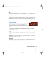
Sub/Noise
The sub-oscillator beefs up the sound by adding a square or triangle wave
an octave below the pitch of osc 1.
The noise generator adds ‘white’ noise to the sound. It is un-pitched, and is
therefore used for percussion sounds, FX such as wind or surf, or for adding a little warmth to pitched sounds.
> SUB SHAPE
This toggles the sub-oscillator waveform between square and triangle.
> NOISE COLOR
Changes the characteristics of the noise generator:
> Middle (0) : Neutral (‘white’ noise, all the frequencies are evenly distributed).
> Negative (-64) : Lowpass (‘pink’ noise, less top and more bass).
> Positive (+63) : Hipass (bright and thin).
Velocity Mod
Several parameters in the Virus PowerCore can be
controlled by velocity. In practice this means that
these parameters can be set to respond to how
hard you press the keys. Think of a traditional piano
– as you hit the keys progressively harder, the notes
become not only louder, but also brighter (more overtones) and even very slightly sharper in
pitch. If you want to program sounds that respond in a really musical way to the nuances of
your keyboard technique, then it’s definitely worthwhile spending some time on this section.
(There again, if your keyboard technique is comparable to that of a one-fingered chimpanzee,
perhaps you should move quickly on!)
Many of the following destinations are bipolar parameters, in which case, positive values
result in a positive offset as velocity increases, whereas negative values result in a negative
offset as velocity increases.
VIRUS POWERCORE MANUAL
THE OSC PAGE
43
indigo powercore manual.book Page 44 Thursday, April 22, 2004 12:23 PM
NOTE: Tip 1: Most of the arpeggiator patterns are programmed with velocity data – so be
sure to experiment with different velocity mod settings in your arp patches!
NOTE: Tip 2: Make sure the target destinations have somewhere to go – for example, there is
no point applying a negative offset to a parameter that is already set to zero!!
NOTE: Tip 3: You will need to make sure your controller keyboard is velocity sensitive to benefit fully from this functionality!
> OSC 1
This determines to what degree Osc 1 Shape is affected by velocity. At positive values, a
positive offset is applied to Osc 1 Shape as you play harder. For example, if Osc 1 Shape is
set to 0, and Osc 1 Vel Mod is set to +64, as you play progressively harder, Osc 1 Shape will
move towards saw, and at full velocity (127) will reach pulse. At negative values, a negative
offset is applied to Osc 1 Shape as you play harder; therefore Osc 1 Shape needs to be set to
something considerably higher than 0 for you to notice any effect here.
> OSC 2
This determines to what degree Osc2 Shape is affected by velocity. (See Osc 1 for more
details).
> PW
This determines to what degree the pulse width of oscillators 1 and 2 are affected by velocity.
At least one of these oscillators need to be set to Shape = +65 or higher before you will notice
any difference here.
> FM
This determines to what degree Osc 2 frequency modulation is affected by velocity. Positive
values result in an increase in FM depth as you play harder, whereas negative values result in
a decrease in FM depth as you play harder.
> VOL
This determines to what degree the patch volume is affected by velocity. Set this to a positive
value for the traditional response, i.e. the harder you play, the louder the note. Negative values have the opposite effect, i.e. the harder you play, the quieter the note!
44
indigo powercore manual.book Page 45 Thursday, April 22, 2004 12:23 PM
> PAN
This determines to what degree panorama is affected by velocity. Positive values mean that
as you play harder the sound will move towards the right speaker, whereas negative values
mean that as you play harder, the sound will move towards the left speaker.
> PUNCH INTENSITY
This determines the volume of the click at the beginning of each note, which can help to add
bite and punch to percussive sounds. This will only be audible if Amp Attack (Easy Page, Filters/Env Page) is set to a very low value.
Unison Mode
In Unison mode, the Virus PowerCore will trigger between 2 and 16
instances of the same voice for every key played, depending on
the chosen value. The voices are then detuned and spread across
the stereo field, resulting in a much fuller sound than is otherwise
possible.
Be aware that Unison mode will reduce the available polyphony by a factor equal to the
number of unison voices!! For instance, a sound that uses Unison Mode = Twin, will have a
maximum polyphony of 8 voices.
> MODE
Use this to switch Unison Mode On or Off and specify the number of voices to be played in
unison.
> DETUNE*
This determines to what degree the unison voices are detuned against each other. Higher values will result in a warmer, thicker sound.
> PAN SPREAD*
This determines the stereo separation between each voice. At 0, all voices are panned centre,
at 127 the voices are spread evenly across the entire stereo field.
VIRUS POWERCORE MANUAL
THE OSC PAGE
45
indigo powercore manual.book Page 46 Thursday, April 22, 2004 12:23 PM
NOTE: If the filters are in Split Mode, then Pan Spread will also affect the stereo separation of
the signals from filter 1 and 2.
> LFO PHASE*
This determines the phase offset between the LFOs in each voice. At extreme settings, the
LFOs of Voice 1 will modulate in opposite phase to the LFOs of Voice 2, resulting in a much
busier sound.
NOTE: *This parameter will have no effect if Unison Mode is Off.
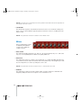
Mixer
Here you will find the controls
for balancing the different
sound sources within the
oscillator section.
> OSC 1/2 BAL
This adjusts the balance between osc1 and osc 2. At –64 you will hear only osc 1, and at +63
only osc 2. At +0 (default) both oscillators are equally balanced.
> OSC 3 VOL
This adjusts the volume of oscillator 3. At a setting of 0, osc 3 will be inaudible (but still active,
so if you don’t intend to hear it at all, better switch it off and free up some polyphony!). To balance it evenly with osc 1 and 2, try setting Osc 3 Vol to 64.
NOTE: This parameter will have no effect if Osc 3 > Osc Mode is set to Off.
> SUB VOL
This adjusts the volume of the sub-oscillator, which is used to make the sound fuller and
deeper by adding an extra tone at a pitch of one octave below osc 1.
46
indigo powercore manual.book Page 47 Thursday, April 22, 2004 12:23 PM
> OSC VOL
This adjusts the overall volume of oscillators 1, 2, 3 and the sub-oscillator in relation to the
ring modulator and noise generator. At a setting of –64, only the ring modulator and noise are
audible. At +0, the oscillators are at maximum volume, and from +0 upwards only the level of
filter saturation is affected. If no saturation curve has been selected (see Filter/Env Page),
then values between +0 and +63 will have no effect.
If the Virus PowerCore is in Input mode, then Osc Vol can be used to adjust the level of the
input signal.
> NOISE VOL
This adjusts the volume of the white noise generator. Noise is often used to create snare
drum or other percussive sounds, but can also be used to create wind and surf fx or add
extra warmth to the oscillators.
> PAN
This adjusts the position of the sound in the stereo field. Virus PowerCore must be enabled as
a stereo insert for this to have any effect.
> PATCH VOL
This adjusts the overall volume of the patch (sound).
> RING VOL
This adjusts the volume of the ring modulator, which multiplies the output of osc 1 and 2 to
create additional harmonic overtones. The result is highly dependent on both the pitch and
waveform of each oscillator. For bell-like tones, try setting both oscillators to a sine wave and
experiment with the semitone settings of each.
> FX SEND
This determines how much of the dry signal is sent to the delay/reverb effect. At 0, the signal
is dry. At 127, only the output of the delay/reverb is audible.
VIRUS POWERCORE MANUAL
THE OSC PAGE
47
indigo powercore manual.book Page 48 Thursday, April 22, 2004 12:23 PM
48
indigo powercore manual.book Page 49 Thursday, April 22, 2004 12:23 PM
The Filter/Env Page
The filter is arguably the most important section of any subtractive synthesizer – it is
here that you determine the overall character of the sound. Filters work by removing
certain frequencies from the signal, leaving only those that are required. The exact way
in which this is done is different for every synthesizer, which is one reason why they all
have such a distinctive character.
The Virus PowerCore is endowed with two filters with a flexible routing system and several modes of saturation, making it possible to achieve all manner of filtering effects.
The controls in this section determine the way in which the signal is routed through the
filters (Series, Parallel or Split) and the kind of saturation (distortion/drive) applied to the
ouptut of filter 1.
VIRUS POWERCORE MANUAL
THE FILTER/ENV PAGE
49
indigo powercore manual.book Page 50 Thursday, April 22, 2004 12:23 PM
> SATURATION
Saturation is the term used to describe the distortion effect applied to the output of filter 1.
Some types just add overtones, whilst others can be used to completely warp the sound
beyond all recognition. Saturation is always post-filter 1 and pre-filter 2, so you can use filter 2 to remove unwanted overtones if you like. Choose between the following types:
Off, Light, Soft, Middle, Hard, Digital, Shaper, Rectifier, BitReduce, RateReduce, Rate+Flw,
LowPass*, Low+Flw*, HighPass* and High+Flw*.
NOTE: Flw means that the amount of saturation applied will be adjusted according to the
MIDI note number (Keyfollow).
NOTE: *These last four options aren’t really saturation effects at all, instead they are additional 1-pole filters.
> OSC VOL
Between values of –64 and 0, this adjusts the overall level of the 3 oscillators and the suboscillator. From 0 to +63, this increases the level of saturation applied to filter 1. If Saturation
is set to Off, then values above 0 will have no effect.
> FILTER ROUTING
Determines the way in which the output of the mixer section is routed through the filters.
NOTE: The more poles a filter has, the more severe the filtering effect.
> Serial 4: The output of the mixer section is routed through filter 1 (+saturation) into filter 2.
Both filters are 2 pole, with a 12dB/Oct slope. This results in a 4 pole filter with a 24 dB
slope.
> Serial 6: The output of the mixer section is routed through filter 1 (+saturation) intofFilter 2.
Filter 1 is 4 pole, 24 dB/Oct, and filter 2 is 2 pole, 12 dB/Oct. This results in a 6 pole filter
with a 36 dB slope.
> Parallel 4: The output of the mixer section is routed through filter 1 (+saturation) and filter 2
simultaneously. Both filters are 2 pole with a 12 dB/Oct slope. In this configuration, the saturation applied to filter 1 is not affected by filter 2.
50
indigo powercore manual.book Page 51 Thursday, April 22, 2004 12:23 PM
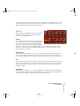
> Split : Like
Parallel
4
mode, the filters run in
parallel, with 2 poles each
(12 dB/Oct), but the difference here is that the filters
each receive different elements of the oscillator
section. Oscillator 1 and
the sub-oscillator are
routed through filter 1
(+saturation), whilst oscilllators 2, 3 and noise are
routed through filter 2. Filter 1 is panned hard left,
and filter 2 is panned hard
right. The depth of panning can be controlled via
Unison Pan Spread (Osc
Page).
> FILTER BALANCE
This balances the output levels of the two filters. The default setting is 12 o'clock (0).
In Serial 4 and Serial 6 modes, this means that the output of filter1 is routed through filter2,
and then to the amplifier section. If filter balance is set to a negative value, then some of the
signal from filter1 (+ saturation) bypasses filter2 and the ouput of filter2 is also reduced. With
filter balance set to -64 only the output of filter1 (+ saturation) is audible. When positive values
are used, some of the mix signal bypasses filter1 and is sent directly into filter2, whilst the
output of filter1 is also reduced. With filter balance set to +63, filter1 is bypassed completely
and only the output of filter2 is audible
In Parallel and Split modes, Filter Balance simply balances the outputs of filter1 and filter2.
VIRUS POWERCORE MANUAL
THE FILTER/ENV PAGE
51
indigo powercore manual.book Page 52 Thursday, April 22, 2004 12:23 PM
Filter 1
> MODE
Select from the following filter types:
> Low Pass: The most commonly
used filter type. Removes frequencies higher than the cutoff point.
> High Pass: Removes
frequencies
lower than the cutoff point.
> Band Pass: Allows only a narrow band of frequencies through - Resonance determines the
width of the band in this case.
> Band Stop: The opposite of Band Pass, this filter removes a narrow band of frequencies.
Often referred to as a 'notch' filter, as it effectively cuts a notch in the tonal spectrum. Resonance determines the width of the notch.
> CUTOFF
This determines the frequency above or below which filter 1 will come into effect. For
instance in a Low Pass filter, frequencies below this point are allowed to pass, and those
above are removed according to the slope of the filter.
> LINK (CUTOFF)
Synchronises the cutoff frequencies of both filters. When switched to ON, filter 2 cutoff
tracks filter 1 cutoff. The offset between the two determined by the Filter 2 Cutoff controller.
> RESONANCE
In Low Pass or High Pass modes, this determines the emphasis of those frequencies near to
the cutoff point. As you increase the level it results in a more nasal or 'honking' tone. In Band
Pass and Band Stop modes, increasing the resonance reduces the width of the band.
> ENV AMT
This determines to what degree the cutoff frequency of filter 1 is affected by the filter envelope.
52
indigo powercore manual.book Page 53 Thursday, April 22, 2004 12:23 PM
> KEYFOLLOW
This determines to what extent the cutoff frequency of filter 2 is affected by MIDI note
number. Positive values will cause the cutoff frequency to increase as you play up the keyboard, negative values will cause it to increase as you play down the keyboard.
> RESO VEL
This determines to what extent the resonance of filter 1 is affected by MIDI velocity. Positive
values mean as you play harder, the resonance increases in intensity. Negative values mean
that as you play harder, the resonance decreases in intensity.
> ENV VEL
This determines to what extent the Filter 1 Env Amt is affected by MIDI velocity. Positive values result in velocities of less than 127 applying a negative offset to the current value of Filter 1 Env Amt. And if you understand that, then you’re doing very well indeed!
I think a practical example is in order:
Set Env Vel to +63, and Filter 1 Env Amt to 127. At this setting, playing as gently as possible
will result in the filter envelope having no effect on the cutoff frequency of filter 1. As you play
harder, the filter envelope has an increasingly noticeable effect until, at maximum velocity, the
effect is equivalent to Filter 1 Env Amt = 127 again.
If Env Vel is set to –64, and filter 1 Env Amt is set to 127, then playing as gently as possible
will result in the filter envelope having maximum effect on the cutoff frequency of filter 1. As
you play harder, the filter envelope has less and less effect until, at minimum velocity, the
effect is equivalent to Filter 1 Env Amt = 0.
NOTE: Positive values are the most common application of this parameter, as it simulates the
way in which the tone of an acoustic instrument becomes brighter the louder it is played.
Many synth sounds benefit from this effect as well.
> ENV POLARITY
Determines which way the filter envelope will sweep the cutoff frequency of filter 1. Normal
polarity means that attack sweeps upwards and decay sweeps downwards. Inverse polarity
effectively turns the filter envelope upside-down i.e. attack sweeps downwards and decay
sweeps upwards.
VIRUS POWERCORE MANUAL
THE FILTER/ENV PAGE
53
indigo powercore manual.book Page 54 Thursday, April 22, 2004 12:23 PM
> LINK (ENVELOPE AMOUNT, RESONANCE, KEY FOLLOW)
When enabled, Env Amt, Resonance and Key Follow become linked with their counterparts in
filter 2, so that both filters can be adjusted simultaneously.
> KEY BASE
This determines the MIDI note number from which the keyfollow parameter will start to have
an effect. To set the key base, either type in the MIDI note number in the text window, or click
on the button and press a key on your controller keyboard or the onscreen keyboard.
Filter 2
> MODE
Selects the filter type:
> Low Pass: The most commonly used filter type. Removes frequencies higher than the cutoff point.
> High Pass: Removes frequencies lower than the cutoff point.
> Band Pass: Allows only a narrow band of frequencies through - Resonance determines the
width of the band in this case.
> Band Stop: The opposite of Band Pass, this filter removes a narrow band of frequencies.
Often referred to as a 'notch' filter, as it effectively cuts a notch in the tonal spectrum. Resonance determines the width of the notch.
> CUTOFF
This determines the frequency above or below which filter 2 will come into effect. For
instance in a lowpass filter, frequencies below this point are allowed to pass, and those above
are attenuated according to the slope of the filter.
> RESONANCE
In Low Pass or High Pass modes, this determines the emphasis of those frequencies near to
the cutoff point. As you increase the level it results in a more nasal or 'honking' tone. In Band
Pass and Band Stop modes, increasing the resonance reduces the width of the band.
54
indigo powercore manual.book Page 55 Thursday, April 22, 2004 12:23 PM
> ENV AMT
This determines to what degree filter 2 cutoff is affected by the filter envelope.
> KEY FOLLOW
This determines to what extent the filter 2 cutoff is affected by MIDI note number. Positive
values will cause the cutoff frequency to increase as you play up the keyboard, negative values will cause it to increase as you play down the keyboard.
> RESO VEL
This determines to what extent the resonance of filter 2 is affected by MIDI velocity. Positive
values mean as you play harder, the resonance increases in intensity. Negative values mean
that as you play harder, the resonance decreases in intensity.
> ENV VEL
This determines to what extent Filter 2 Env Amt is affected by MIDI velocity. Positive values
result in velocities of less than 127 applying a negative offset to the current value of Filter 2
Env Amt. And if you understand that, then you’re doing very well indeed!
I think a practical example is in order:
Set Env Vel to +63, and Filter 2 Env Amt to 127. At this setting, playing as gently as possible
will result in the filter envelope having no effect on the cutoff frequency of filter 2. As you play
harder, the filter envelope has an increasingly noticeable effect until, at maximum velocity, the
effect is equivalent to Filter 2 Env Amt = 127 again.
If EnvVel is set to –64, and Filter 2 Env Amt is set to 127, then playing as gently as possible
will result in the filter envelope having maximum effect on the cutoff frequency of filter 2. As
you play harder, the filter envelope has less and less effect until, at minimum velocity, the
effect is equivalent to Filter 2 Env Amt = 0.
Positive values are the most common application of this parameter, as it simulates the way in
which the tone of an acoustic instrument becomes brighter the louder it is played. Many
synth sounds benefit from this effect as well.
VIRUS POWERCORE MANUAL
THE FILTER/ENV PAGE
55
indigo powercore manual.book Page 56 Thursday, April 22, 2004 12:23 PM
> ENV POLARITY
Determines which way the filter envelope will sweep the cutoff frequency of filter 2. Normal
polarity means that attack sweeps upwards and decay sweeps downwards. Inverse polarity
effectively turns the filter envelope upside-down i.e. attack sweeps downwards and decay
sweeps upwards.
Filter Envelope
The filter envelope is used to automatically
control the cutoff frequency over a certain
time period. In order for these parameters to
have any effect on the sound, Filter 1 Env
Amt and/or Filter 2 Env Amt must be set to a
positive value.
> ATTACK
This determines how long it takes for the envelope to reach its peak.
> DECAY
This determines how long it takes for the envelope to decay from its peak to the sustain level.
> SUSTAIN
This determines the level at which the envelope will sustain.
> SUSTAIN TIME
This determines how long the envelope will remain at the sustain level. At 0, the sustain level
will be maintained as long as the key is held. At positive values, the envelope will rise back up
to its peak level (the higher the value, the quicker the rise). At negative values, the envelope
will sweep down to its minimum level (the lower the value, the quicker the fall).
> RELEASE
This determines how long the envelope will take to fall to its minimum level after the key is
released. The higher the value, the longer it will take.
56
indigo powercore manual.book Page 57 Thursday, April 22, 2004 12:23 PM
Amplifier Envelope
The amp envelope affects patch volume in the same way
that the filter envelope affects frequency cutoff. Use this to
automatically control the volume of a sound over time.
> ATTACK
This determines how long it takes for the sound to reach maximum volume.
> DECAY
This determines how long it takes for the sound to decay from maximum volume to the sustain volume.
> SUSTAIN
This determines the volume at which the sound will sustain as long as the key is held.
> SUSTAIN TIME
At +0, the sound will remain at the sustain level so long as the key is held. At positive values,
the volume will rise to maximum (the higher the value, the quicker the rise). At negative values, the volume will fall to silence (the lower the value, the quicker the fall).
> RELEASE
This determines how long it takes for the sound to fade to silence once the key is released.
Higher values result in a slower fade.
VIRUS POWERCORE MANUAL
THE FILTER/ENV PAGE
57
indigo powercore manual.book Page 58 Thursday, April 22, 2004 12:23 PM
58
indigo powercore manual.book Page 59 Thursday, April 22, 2004 12:23 PM
The LFO Page
LFO is an abbreviation of Low Frequency Oscillator. Basically, these generate waveforms that oscillate so slowly that they are only useful as a modulation source for other
parameters, such as pitch, cutoff, panorama etc. The Virus PowerCore has 3 LFOs.
VIRUS POWERCORE MANUAL
THE LFO PAGE
59
indigo powercore manual.book Page 60 Thursday, April 22, 2004 12:23 PM
LFO 1
The controls in this section are used to affect the characteristics of
LFO 1, and determine which parameters it will modulate.
> RATE
This determines how fast LFO 1 will oscillate. The higher the value,
the faster it will oscillate.
> CLOCK
This overrides Rate and forces LFO 1 to sync its wave cycle to the
clock control. The fractions are relative to a whole note, or semibreve, which in turn are equivalent to a whole bar/measure in 4/4
time. So, by choosing a clock rate of 1/4, LFO 1 will sync to a quarter note (crotchet) cycle, whereas a setting of 4/1 will cause it to
sync to cycle of 4 bars.
> SHAPE
This determines the waveform of LFO 1 - different waves can result in very different modulation effects. Choose between the following options:
>Sine: A smooth up/down cyclic wave.
>Triangle: Similar to sine wave, but with sharper peaks and a linear curve.
>Sawtooth : This will cause the sound to rise/fall, then jump back suddenly to rise/
fall again.
>Square: Use this to jump back and forth between two values.
>Sample and Hold (Random): This isn’t a waveform as such – instead LFO1 will
generate random values, causing the affected parameter(s) to jump around unpredictably.
>Sample and Glide : Like Sample and Hold, this generates random values
between which the LFO will interpolate smoothly, causing the affected parameter(s)
to slide up and down unpredictably.
60
indigo powercore manual.book Page 61 Thursday, April 22, 2004 12:23 PM
>Oscillator Waveform : Selecting this button will open up a window from
which you can choose any of the 62 spectral waves.
> CONTOUR
This determines the contour or slope of the currently selected waveform. It basically has the
effect of ‘squashing’ the waveform from one side or the other, depending on whether you
enter a positive or negative value. For instance by using extreme values you can turn a triangle wave into a rising or falling ‘ramp’ wave. You can also use this parameter to adjust the
pulse width of the pulse (square) waveform.
NOTE: If the current waveform is one of the spectral waveforms, then negative values will
‘zoom’ into the wave. Positive values will have no effect on the spectral waveforms.
> ENV MODE
When enabled, the LFO will only cycle through the waveform once. This effectively turns the
LFO into an additional envelope which is shaped according to the currently selected waveform.
> KEY FOLLOW
This determines to what extent LFO rate is affected by MIDI note number. When set to Off,
the LFO will oscillate at the same frequency regardless of which key is played. When set to
127, the frequency will increase the higher you play up the keyboard. Lesser values result in a
more subtle increase.
> KEY TRIG
When set to Off, the LFO is free-running. When set to any other value, the LFO is forced to
start its cycle at the same point as soon as a key is played. Changing the value moves the
start point along the wave cycle.
> LFO MODE
When set to Mono, LFO 1 is applied to each voice (note) in sync. When set to Poly, each
voice is modulated independently.
NOTE: Note: there will only be a difference between these two modes as long as Key Trig is
set to Off and LFO 1 is not in clock mode.
VIRUS POWERCORE MANUAL
THE LFO PAGE
61
indigo powercore manual.book Page 62 Thursday, April 22, 2004 12:23 PM
> OSC 1
Determines the amount of modulation applied to the pitch of osc1.
> OSC 2
Determines the amount of modulation applied to the pitch of osc 2.
> LINK (OSC1 & OSC2)
When enabled, adjusts the amounts of LFO 1-> Osc 1 and LFO 1->Osc 2 simultaneously.
> PW 1+2
Determines the amount of modulation applied to the pulse widths of oscillators 1 and 2. One
or both of these oscillators must be set to a square wave for this parameter to have an effect.
> RESO 1+2
Determines the amount of modulation applied to the resonance of filters 1 and 2.
> ASSIGN AMT
Determines the amount of modulation applied to the parameter selected in the Assign Destination window.
> ASSIGN DESTINATION
Select virtually any parameter in the Virus PowerCore to be modulated by LFO 1.
> FILTER GAIN
Determines the amount of modulation applied to the input gain to the filter section. This is
often used to create tremolo effects (try a sine or triangle wave).
62
indigo powercore manual.book Page 63 Thursday, April 22, 2004 12:23 PM
LFO 2
The controls in this section are used to affect the characteristics of
LFO 2, and determine which parameters it will modulate. Many of the
parameters are identical in function to their counterparts in LFO 1.
> RATE
This determines how fast LFO 2 will oscillate. The higher the value,
the faster it will oscillate.
> CLOCK
This overrides Rate and forces LFO 2 to sync its wave cycle to the
clock control. The fractions are relative to a whole note, or semibreve, which in turn are equivalent to a whole bar/measure in 4/4
time. So, by choosing a clock rate of 1/4, LFO 2 will sync to a quarter
note (crotchet) cycle, whereas a setting of 4/1 will cause it to sync to
cycle of 4 bars.
> SHAPE
This determines the waveform of LFO 2 - different waves can result in very different modulation effects. Choose between the following options:
>Sine: A smooth up/down cyclic wave.
>Triangle: Similar to sine wave, but with sharper peaks and a linear curve.
>Sawtooth : This will cause the sound to rise/fall, then jump back suddenly to rise/
fall again.
>Square: Use this to jump back and forth between two values.
>Sample and Hold (Random): This isn’t a waveform as such – instead LFO1 will
generate random values, causing the affected parameter(s) to jump around unpredictably.
>Sample and Glide : Like Sample and Hold, this generates random values
between which the LFO will interpolate smoothly, causing the affected parameter(s)
to slide up and down unpredictably.
VIRUS POWERCORE MANUAL
THE LFO PAGE
63
indigo powercore manual.book Page 64 Thursday, April 22, 2004 12:23 PM
>Oscillator Waveform : Selecting this button will open up a window from
which you can choose any of the 62 spectral waves.
Clicking on this box will open up a window from which you can choose any of the 62 spectral waves.
> CONTOUR
This determines the contour or slope of the currently selected waveform. It basically has the
effect of ‘squashing’ the waveform from one side or the other, depending on whether you
enter a positive or negative value. For instance by using extreme values you can turn a triangle wave into a rising or falling ‘ramp’ wave. You can also use this parameter to adjust the
pulse width of the pulse (square) waveform.
NOTE: If the current waveform is one of the spectral waveforms, then negative values will
‘zoom’ into the wave. Positive values will have no effect on the spectral waveforms.
> LFO MODE
When set to Mono, LFO 2 is applied to each voice (note) in sync. When set to Poly, each
voice is modulated independently.
Note: there will only be a difference between these two modes as long as Key Trig is set to
Off and LFO 2 is not in Clock Mode.
> KEY FOLLOW
This determines to what extent LFO 2 Rate is affected by MIDI note number. When set to Off,
LFO 2 will oscillate at the same frequency regardless of which key is played. When set to 127,
the frequency will increase the higher you play up the keyboard. Lesser values result in a
more subtle increase.
> FILTER 1
Determines the amount of modulation applied to the cutoff frequency of filter .
> FILTER 2
Determines the amount of modulation applied to the cutoff frequency of filter 2.
64
indigo powercore manual.book Page 65 Thursday, April 22, 2004 12:23 PM
> LINK (FILTER 1& FILTER 2)
When enabled, adjusts the cutoff frequencies of filter 1 and filter 2 simultaneously.
> SHAPE 1+2
Determines the amount of modulation applied to osc 1 Shape and osc 2 Shape.
> PANORAMA
Determines the amount of modulation applied to the stereo pan position.
> ASSIGN AMOUNT
Determines the amount of modulation applied to the parameter selected in the Assign Destination window.
> ASSIGN DESTINATION
Select virtually any parameter in the Virus PowerCore to be modulated by LFO 2.
> FM AMT
Determines the amount of modulation applied to osc 2 FM amount.
VIRUS POWERCORE MANUAL
THE LFO PAGE
65
indigo powercore manual.book Page 66 Thursday, April 22, 2004 12:23 PM
LFO 3
The controls in this section are used to affect the characteristics of
LFO 3, and determine which parameter(s) it will modulate. Many
parameters are identical in function to their equivalents in LFOs 1and
2.
NOTE: Note: the functionality of LFO 3 is not the same as that of
LFO 1 and 2. This LFO is designed for creating vibrato effects, and as
such only has one destination slot.
NOTE: Tip: If you want LFO 3 to modulate other parameters, you can
choose it as a Source in the Mod Matrix (See ModMatrix page).
> RATE
This determines how fast LFO 3 will oscillate. The higher the value,
the faster it will oscillate.
> CLOCK
This overrides Rate and forces LFO 3 to sync its wave cycle to the clock control. The fractions are relative to a whole note, or semibreve, which in turn are equivalent to a whole bar/
measure in 4/4 time. So, by choosing a clock rate of 1/4, LFO 3 will sync to a quarter note
(crotchet) cycle, whereas a setting of 4/1 will cause it to sync to cycle of 4 bars.
> SHAPE
This determines the waveform of LFO 3 - different waves can result in very different modulation effects. Choose between the following options:
>Sine: A smooth up/down cyclic wave.
>Triangle: Similar to sine wave, but with sharper peaks and a linear curve.
>Sawtooth : This will cause the sound to rise/fall, then jump back suddenly to rise/
fall again.
>Square: Use this to jump back and forth between two values.
66
indigo powercore manual.book Page 67 Thursday, April 22, 2004 12:23 PM
>Sample and Hold (Random): This isn’t a waveform as such – instead LFO1 will
generate random values, causing the affected parameter(s) to jump around unpredictably.
>Sample and Glide : Like Sample and Hold, this generates random values
between which the LFO will interpolate smoothly, causing the affected parameter(s)
to slide up and down unpredictably.
>Oscillator Waveform : Selecting this button will open up a window from
which you can choose any of the 62 spectral waves.
> FADE IN
If set to 0, LFO 3 will be fully effective as soon as a note is played. At values of 1 – 127, LFO 3
takes a certain amount of time to develop in intensity. Use this to simulate how a string or
woodwind player gradually introduces vibrato on longer notes.
> LFO MODE
When set to Mono, LFO 3 is applied to each voice (note) in sync. When set to Poly, each
voice is modulated independently.
Note: there will only be a difference between these two modes as long as Key Trig is set to
Off and LFO 3 is not in Clock Mode.
> KEY FOLLOW
This determines to what extent LFO Rate is affected by MIDI note number. When set to Off,
the LFO will oscillate at the same frequency regardless of which key is played. When set to
127, the frequency will increase the higher you play up the keyboard. Lesser values result in a
more subtle increase.
> ASSIGN AMOUNT
Determines the amount of modulation applied to the parameter selected in the Assign Destination window.
> ASSIGN DESTINATION
Choose the parameter(s) to be modulated by LFO 3. Choose between:
> Osc1 Pitch: LFO 3 will modulate the pitch of oscillator 1.
VIRUS POWERCORE MANUAL
THE LFO PAGE
67
indigo powercore manual.book Page 68 Thursday, April 22, 2004 12:23 PM
> Osc1+2 Pitch: LFO 3 will modulate the pitch of oscillator 2.
> Osc2 Pitch: LFO 3 will modulate the pitch of osc1 and oscillator 2.
> Osc1 PulseWidth*: LFO 3 will modulate the pulse width of oscilator 1.
> Osc1+2 PulseWidth*: LFO 3 will modulate the pulse width of oscillator 1 and oscillator 2.
> Osc2 PulseWidth*: LFO 3 will modulate the pulse width of oscillator 2.
> Osc2 SyncPhase: LFO 3 will modulate the phase position of oscillator2 when it is synced
to oscillator1 via the sync function (Osc Page).
* This will only have an audible effect if the relevant oscillators are set to generate a pulse
wave (Osc Page).
68
indigo powercore manual.book Page 69 Thursday, April 22, 2004 12:23 PM
The FX-1 Page
Here you will find the controls for the Analog Boost, Input Ring Modulator, Phaser, Patch
Distortion, Chorus and Delay/Reverb effects as well as the output selection for the current part.
VIRUS POWERCORE MANUAL
THE FX-1 PAGE
69
indigo powercore manual.book Page 70 Thursday, April 22, 2004 12:23 PM
Analog Boost
This effect imbues your sound with the kind of bottom-end warmth more commonly associated with analogue synthesizers, by emphasizing certain frequencies.
> INTENSITY
This determines the degree of emphasis applied to the sound.
> TUNE
This determines the central frequency around which the emphasis will occur.
Ring Mod
With this effect you can ring-modulate an audio input signal with the oscillators of
the Virus PowerCore. This means that the signals from the inputs and the oscillators
are multiplied. The end result will vary greatly depending on the settings of the
oscillators – try choosing a sine wave for both oscillator 1 and 2, and experiment
with different pitches for each.
> MIX
This determines the balance between the oscillators, ring mod and audio input signals. At 0,
the effect is Off, and only the output of the oscillators can be heard. As the value increases
from 1 to 64 the level of the ring mod is increased until at 64, only the ring modulation is audible. As the value increases from 65 towards 127, the ring mod signal is dialed out of the mix,
being gradually replaced with the audio input signal (see “Using the Audio Inputs” on
page 83). At 127, only the audio input signal is audible.
Phaser
Use the phaser to achieve the sweeping, swooshing effect made popular in
the 60s and 70s by many psychedelic
and prog-rock artists.
70
indigo powercore manual.book Page 71 Thursday, April 22, 2004 12:23 PM
The phaser will also turn a mono sound into stereo.
> MIX
Determines the balance between the dry signal and the phaser effect. At 0, the phaser is Off.
At 127, the signal is 100% wet.
> RATE
Determines how fast the phaser will sweep through the frequency spectrum.
> DEPTH
Determines the frequency range through which the phaser will sweep. The higher the value,
the greater the intensity of the phasing effect.
> FREQUENCY
Determines the center frequency about which the phaser will sweep.
> STAGES
Determines the number of filter stages used to create the phasing effect. The higher the
number, the more complex the effect becomes.
> SPREAD
Determines the bandwidth of the phaser’s filters.
> FEEDBACK
Determines the amount of signal to be fed back into the phaser. Experiment with both positive and negative values for different types of extreme phasing.
VIRUS POWERCORE MANUAL
THE FX-1 PAGE
71
indigo powercore manual.book Page 72 Thursday, April 22, 2004 12:23 PM
Patch Distortion
Use Patch Distortion to add saturation or clipping effects to the
patch as a whole. Although the list is very similar to that of filter saturation (see Filter Page), the effect is quite different, as all the voices
(notes) go through the same instance of the distortion effect. This
means that the intensity of the distortion is enhanced as you play more notes simultaneously,
whereas filter saturation is applied to each voice individually.
> INTENSITY
Determines the level of distortion. In the case of LowPass and HighPass (1-pole filters), this
determines the cutoff frequency.
> CURVE
Choose from Off, Light, Soft, Middle, Hard, Digital, Shaper, Bit Reducer, Rate Reducer, LowPass and HighPass.
Chorus
Use the renowned Virus chorus effect to add depth
and movement to the sound. The chorus works by
adding a delayed copy to the original signal and
modulating the delay time with an LFO to create a
detuned effect. Like the phaser, this will also convert
a mono sound into stereo.
> MIX
Determines the balance between the original signal and the chorus signal. At 0 the effect is
Off, at 64, the balance is equal, and at 127 only the output of the chorus is audible. It usually
makes sense to set Mix at a value somewhere between 0 and 64, as both signals are required
to achieve the chorusing effect.
> RATE
Determines the rate of the chorus LFO.
72
indigo powercore manual.book Page 73 Thursday, April 22, 2004 12:23 PM
> DEPTH
Determines the depth of modulation applied to the chorus delay time. Use this to increase the
intensity of the chorusing effect.
> DELAY TIME
Determines the time-delay between the original signal and the output of the chorus effect.
Longer times result in a warmer sound, whilst very short times result in a flanging effect.
NOTE: Tip:: Set Chorus Delay Time to 0 and increase the Chorus Feedback amount to boost
the levels of quieter sounds.
> FEEDBACK
Determines the amount of signal to be fed back into the chorus. At extreme values this can
create an intense, howling effect which can easily overload your equipment and your ears, so
approach with caution!
> SHAPE
Determines the wave shape of the chorus LFO. Triangle is the default, but you might want to
experiment with the other options for more exotic effects.
Output
The Virus PowerCore has 4 pairs of stereo output channels. Here you can choose
to which output channel the currently selected part is sent.
NOTE: Remember the signal being sent to any particular output channel is predelay/reverb. The delay/reverb signal is always sent to output 1.
VIRUS POWERCORE MANUAL
THE FX-1 PAGE
73
indigo powercore manual.book Page 74 Thursday, April 22, 2004 12:23 PM
Delay/Reverb
Use the controls in this section to determine the characteristics
of the delay/reverb effect. Delay is used to create complex echo
effects and reverb is used to simulate the effect of being in an
acoustic space, such as a room or hall.
> USE GLOBAL FX FROM
The Virus PowerCore has just one global delay or reverb per
DSP, therefore only one part can control the parameters of the
Delay/Reverb at any given time.
Click on this box to select which Part shall control
the Delay/Reverb effect.
All currently active Parts sharing the same DSP will
use the delay/reverb settings from the Part
selected here. The delay/reverb controls will be
greyed out in the other three Parts.
NOTE: Remember that although there is only one
Global Delay/Reverb per DSP, each Part still has it’s
own individual Send parameter.
> MODE
Select the type of effect to be used. Options
include Delay, Reverb, Reverb+Feedback and several ‘Groove’ delays which can be used for
complex rhythmic effects
> Off: When switched to Off, the Delay/Reverb effect is deactivated.
> Delay: Use this for a simple echo effect where each repeat is evenly spaced.
> Reverb: Use this to create the effect of an acoustic space, such as a room or a hall.
74
indigo powercore manual.book Page 75 Thursday, April 22, 2004 12:23 PM
> Reverb+Feedback 1: This variation of the reverb algorithm feeds the pre-delay signal
back into itself to create rhythmic repetitions of the reverb signal.
> Reverb+Feedback 2: This behaves in a similar fashion to Reverb+Feedback 1, with the
only difference being that the Reverb is audible immediately after the dry signal.
NOTE: Tip: When using either of the Reverb+Feedback algorithms, try using Ambience or
Small Room reverb type, as both of these offer reasonably long pre-delay times. Set a short
reverb time, a long pre-delay and set reverb feedback to a high value. These settings should
give you a good indication of the purpose of these algorithms.
> Delay X:Y: These are ‘ping-pong’ delays, which means that the delay times for the left and
right channels are different, making the sound appear to bounce back and forth between
the speakers, like a ping-pong ball. The different ratios refer to the relationship between the
left and right signals, i.e. 2:1 means that the left delay time is twice the length of the right
delay time.
> Pattern X+Y: These ‘Pattern’ delays are also ping-pong delays, but instead of referring to
the delay time or clock parameters, they refer instead to the global tempo. The two numbers represent how many sixteenth note (semiquaver) increments the left and right channels will be delayed by. Note that neither Delay Time nor Delay Clock will have any effect in
this mode.
NOTE: Tip: Try using these ‘Groove’ delays in conjunction with the arpeggiator to create
interesting rhythmic patterns.
> SEND
Determines them amount of the dry signal to be sent to the delay/reverb effect. This behaves
exactly like a post-fader effect bus on a mixing console. As the value nears 127, the dry signal
is faded out and only the delay/reverb signal is audible.
VIRUS POWERCORE MANUAL
THE FX-1 PAGE
75
indigo powercore manual.book Page 76 Thursday, April 22, 2004 12:23 PM
Delay
> TIME
Determines the length of the delay time in milliseconds, to a maximum of 693.6ms.
> CLOCK
This slaves the delay time to the global tempo or incoming MIDI Clock signal. Choose a note
value that represents the desired delay time i.e. a Clock value of 1/4 will result in quarter note
(crotchet) repeats.
NOTE: Note: The maximum delay time is 693.6 ms, so if the current clock setting requires a
delay time longer than this, it will automatically be adjusted to half the value i.e. 1/2 will sound
as 1/4.
> FEEDBACK
Determines the amount of signal to be fed back into the delay. The higher the value, the more
repetitions you will hear.
> COLORATION
Determines the character of the delay by applying a filter to the delayed signal. At +0 the
character is unchanged. Negative values apply a lowpass filter, resulting in a duller, warmer
sound. Positive values apply a highpass filter, resulting in a much thinner, brighter sound.
> RATE
Determines the rate of modulation applied to the delay time by the delay LFO.
> DEPTH
Determines the amount of modulation applied to the delay time. Higher values result in
strange effects that can be made even more interesting if Rate is set to a high value.
> SHAPE
Determines the wave shape for the delay LFO. The default setting is Triangle, but you might
want to experiment with the other shapes for more extreme effects.
76
indigo powercore manual.book Page 77 Thursday, April 22, 2004 12:23 PM
NOTE: Using different shapes for the delay LFO can result in audible artefacts.
Reverb
Use these controls to affect the various characteristics of the reverb effect.
> DECAY TIME
Determines the length of the decay or ‘tail’ of the reverberation.
> TYPE
Select from one of 4 types of reverb: Ambience, Small Room, Large Room or Hall.
NOTE: Ambience is useful for creating a sense of space around a sound, but isn’t the most
realistic of the available algorithms. The advantage is that, due to the lower calculation
required, a much longer pre-delay is possible than with the other types.
> DAMPING
Determines the degree of high frequency damping. As a sound bounces around a room, the
high frequencies get gradually attenuated, especially by soft furnishings, carpets etc. As the
value increases, the more quickly the high frequencies are damped in the reverb tail.
> COLORATION
Determines the character of the reverb tail. This behaves exactly like Delay Coloration, by
applying a lowpass filter (negative control range) or highpass filter (positive control range) to
the reverb signal. To create natural sounding reverb effects, you should only use negative
amounts, which will result in a warmer, darker sound. If you wish to experiment with thin
reverbs where the lower frequencies are attenuated instead, then try positive values.
> PRE-DELAY
Determines the time delay between the dry signal and the start of the room reflections.
Longer values can be useful for creating the illusion of a wider space.
VIRUS POWERCORE MANUAL
THE FX-1 PAGE
77
indigo powercore manual.book Page 78 Thursday, April 22, 2004 12:23 PM
The maximum pre-delay times available depend on the reverb type, ranging from 150ms
(Hall) to 500ms (Ambience).
> CLOCK
Selects a clock-synchronised pre-delay time. This is particularly useful for the Reverb+Feedback algorithms, as the repeats can be synchronised in the same way as in the delay. (See
Delay Clock for further explanation.)
> FEEDBACK
This parameter is only functional in the Reverb+Feedback modes. It determines the amount
of signal to be fed back into the reverb. Higher values result in more repeats of the early
reflections. To emphasise this effect, try using short reverb times and a long pre-delay.
78
indigo powercore manual.book Page 79 Thursday, April 22, 2004 12:23 PM
The FX2/Global Page
On this page you will find the controls for the Vocoder, Envelope Follower, External
Audio Input, Arpeggiator as well as Global Tuning, Key Mode, Pitch Wheel etc.
VIRUS POWERCORE MANUAL
THE FX2/GLOBAL PAGE
79
indigo powercore manual.book Page 80 Thursday, April 22, 2004 12:23 PM
Vocoder
> ABOUT THE VOCODER
The Vocoder is used to take the harmonic and dynamic properties of one signal (the modulator) and impose them on another (the carrier). The most widely known application of this is to
make ‘talking’ synth sounds by using a voice as the modulator and an oscillator waveform as
the carrier. Those of you old enough to remember Sparky’s Magic Piano will know this effect
well, but the most famous proponents of the vocoder are probably Kraftwerk, who have made
extensive use of this effect. Another popular and highly effective technique is to use the Vocoder to process drum loops.
So how does it work? Well, the vocoder applies a series of bandpass filters and envelope followers to the modulator signal and uses the resulting signal to modulate the equivalent frequencies in the carrier signal. Widely different results can be achieved depending on the
number of bands used, the sensitivity of the envelope followers and the frequency content of
each signal.
NOTE: The vocoder is the most complex of the Virus PowerCore’s effects, and takes a lot of
DSP calculating power; therefore the filter section becomes disabled when you use it, and
polyphony is reduced. If you need to filter the output of the vocoder, then open up another
instance of the Virus PowerCore, and use the audio inputs to process the output of the first
(Extended License only).
NOTE: In order to make use of the vocoder, you may need to instance the Virus PowerCore
as a side-chain effect. See the chapter “Using the Audio Inputs” for more information.
> MODE
Use this to select the source of the carrier signal.
80
indigo powercore manual.book Page 81 Thursday, April 22, 2004 12:23 PM
> Off: The vocoder is disabled.
> Osc: The output of the oscillators, including noise and ring mod, provides the signal for the
carrier.
> Osc Hold: The same as Osc mode, but with key latch.
> Noise: The output of the noise generator is used for the carrier signal.
> Input: The audio inputs provide the signal for the carrier. This means that the same signal is
used for both carrier and modulator, which can result in some very interesting effects.
> CENTER FREQ
Determines the central frequency of the bandpass filters in the modulator and carrier banks.
> MOD OFFSET
Use this to offset the center frequency of the modulator bank relative to the carrier bank.
> MOD Q
Determines the width of the gap between the bandpass filters in the modulator bank. This is
unlikely to have more than a very subtle effect on the sound.
> MOD SPREAD
Determines the spread of the bandpass filters in the modulator bank. Lower values mean a
narrower spectrum of the modulator signal is applied to the carrier signal. A value of +63
means that the whole frequency spectrum of the modulator signal is applied to the carrier
signal.
> CARR Q
Determines the resonance or quality of the filters bands in the carrier bank. Lower values will
result in a fairly neutral tone, whereas higher values result in a more artificial sound.
> LINK
With Link enabled, Carr Q and Mod Q are adjusted simultaneously, as are Mod Spread and
Carr Spread.
VIRUS POWERCORE MANUAL
THE FX2/GLOBAL PAGE
81
indigo powercore manual.book Page 82 Thursday, April 22, 2004 12:23 PM
> CARR SPREAD
Determines the spread of the bandpass filters in the carrier bank. Low values result in a narrow frequency spectrum, whilst a value of +63 results in the entire frequency spectrum being
covered in the carrier signal. The value chosen for this parameter can have a dramatic affect
on the intelligibility of speech.
> SPECTRAL BAL
Determines the spectral balance between the higher and lower frequencies of the vocoder
signal. This parameter has a lot of influence on the overall character of the vocoder.
> BANDS
Determines the number of bandpass filters used by the vocoder. It is possible to choose
between 1 and 32 filter bands. Less filter bands result in a more typical vocoder sound,
whereas more filter bands increase the intelligibility of speech. The more filter bands there
are, the more calculating power is required, so polyphony might vary depending on the number of active filter bands.
> ATTACK
Determines the response time of the vocoder’s envelope followers. With longer attack times,
the response of the vocoder will become slower, reducing the intelligibility of speech.
> RELEASE
Determines the release time of the vocoder’s envelope followers. With longer release times,
the definition of the signal peaks becomes blurred, reducing intelligibility.
> SOURCE BAL
Determines the balance between the source signals and the vocoder signal. At +0 (default)
only the output of the vocoder is heard. Negative values add a certain amount of the carrier
signal to the vocoder signal, whereas positive values add a certain amount of the modulator
signal. At either extreme, you will hear only the carrier or modulator signals respectively.
82
indigo powercore manual.book Page 83 Thursday, April 22, 2004 12:23 PM
Using the Audio Inputs
The two audio input channels allow you to
pass an external audio signal through the filters, amplifier and effects sections of the
Virus PowerCore. A typical application of
this technique is to run a drum-loop through
a lowpass filter, but with the Virus PowerCore’s powerful modulation capabilities, the
possibilities for sonic manipulation go a lot further than this!
> USING THE SIDE-CHAIN PLUGIN
Not all VST host software will allow you to route audio
data into a VST instrument, so for this reason we have
included the Virus Input plugin which sets up a sidechain between the audio track and the Virus PowerCore plugin. Latency is compensated as soon as the
relevant information is provided by the host software.
To use this, you first need to instance the Virus PowerCore as an audio instrument, so that the
input plugin has something to connect to. Now, in the audio track you wish to process, select
‘Virus Input’ from the PowerCore folder in the VST menu.
Now click on the Destination window, and choose the Virus instance from the menu. The output of the audio track will now be routed into the Virus plugin.
NOTE: If your host software provides side-chaining capabilities, or allows audio to be routed
to a VSTi then you should use these methods instead, as the side-chain plugin may not
behave correctly under such hosts. Note that you may have to instance the Virus PowerCore
as a multi-channel instrument in order to access the side-chain functionality.
> MODE
Enables the external audio inputs.
> Off: the audio inputs are disabled.
> Dynamic: In Dynamic mode, the audio signal is passed through the amp envelope as well
as the filters (inc. saturation) and effects. This means that no signal is heard until you press
a key, and the volume curve of the signal will follow the shape of the amp envelope.
VIRUS POWERCORE MANUAL
THE FX2/GLOBAL PAGE
83
indigo powercore manual.book Page 84 Thursday, April 22, 2004 12:23 PM
> Static: In Static mode, the audio signal is passed through the filters and effects sections,
but bypasses the amp envelope. This means that the signal can be heard continuously,
regardless of any keys played.
> To Effects: Use this mode if you wish to bypass the filter section and send the input signal
straight to the effects section of the Virus PowerCore. This mode does not reduce polyphony
NOTE: When in Dynamic or Static modes, the polyphony will be reduced by two voices.
NOTE: In both modes, the level of the external audio signal can be attenuated by the Osc Vol
control (Global Page).
Envelope Follower
The envelope follower replaces the filter envelope with an
envelope that is dynamically controlled by an external audio
signal. In other words, the external audio signal is continuously monitored, and the peaks and troughs in the signal are
translated into data which can be used to control the levels
of other parameters. A typical application of this would be to use a drum-loop to modulate
the filter cutoff frequency of a pad sound.
NOTE: See the chapter “Using the Audio Inputs” for instructions on how to route an audio
signal into the Virus PowerCore.
> MODE
Enables the envelope follower. If you are using multiple instances of the Virus PowerCore on
the same DSP, only one can use the envelope follower.
By default, the envelope follower modulates the cutoff frequency of filter 1 and filter 2, but
because it replaces the filter envelope, you will need to adjust Env Amt (Filter page) of one or
both filters to hear any effect. If you need the envelope follower to modulate another parameter, then use the Mod Matrix (see Mod Matrix page) and choose ‘Filter Envelope’ as the modulation source.
84
indigo powercore manual.book Page 85 Thursday, April 22, 2004 12:23 PM
> LEVEL
Determines the sustain level of the envelope follower. This has a significant influence on the
intensity of the effect, and it is recommended that you start with a value of 127 and reduce as
necessary.
> ATTACK
Determines the envelope follower’s response time to the incoming signal peaks. It is recommended that you start with a value of 0 and only increase Attack if you require a softer
response.
> RELEASE
Determines the rate at which the envelope follower responds to a reduction in the input signal
strength. Lower values result in a more dynamic, grittier sound, whereas higher values result
in a smoother sound which still contains a rhythmic element.
Global
The following parameters are global i.e. they affect each part/channel of the current
instance in the same way.
> TUNE
Determines the tuning of all parts within the current instance. Default is 0 (A=440Hz).
> TEMPO
Determines the tempo of the Virus PowerCore’s internal clock, which is used to control
the rate of all the clock-syncable parameters, such as the arpeggiator, delay and lfo’s. If MIDI
Clock data is being received from the host software, this controller will be greyed out and
unavailable for adjustment.
> SYNC
Use this button to determine whether the Virus PowerCore synchronises it’s tempo to the
clock signal generated by the host software, or whether it uses it’s own internal clock.
VIRUS POWERCORE MANUAL
THE FX2/GLOBAL PAGE
85
indigo powercore manual.book Page 86 Thursday, April 22, 2004 12:23 PM
NOTE: The state of this button is saved with the project data by your host software, i.e. it is
not saved within the patch.
> Extern: The Virus will automatically synchronise to the clock signal generated by the host
application. In this mode, the Tempo control will be greyed out.
> Intern: The Virus ignores the clock signal generated by the host software and uses the
tempo as set within the patch. Only the tempo setting of the patch in part 1 is used, as it is
not possible to have multiple tempi within the same DSP.
Pitch
The following controls determine the overall pitch and tuning offset for the
current patch.
> TRANSPOSE
Determines the pitch offset in semitone increments for the current patch. You can transpose a
patch down to 64 semitones lower, or up to 63 semitones higher. All oscillators keep their relative intervals between each other.
> OCTAVE
Use the Octave buttons to transpose the pitch in octave increments, up to 4 octaves higher
or lower.
> DETUNE
Determines the overall detuning of the patch. This is a subtle effect which is similar to Osc 2/
3 Detune, but applied to all oscillators simultaneously. Like Osc2/3 Detune, this is affected by
MIDI note number i.e. there is a subtle keyfollow applied to the intensity of the detuning.
NOTE: Use Detune to increase the overall warmth when playing more than one sound from
different parts within the same instance of the Virus PowerCore.
86
indigo powercore manual.book Page 87 Thursday, April 22, 2004 12:23 PM
Pitch Wheel
The pitch wheel (also known as a pitch bender) is a controller found on
pretty much all keyboard controllers. It usually takes the form of a sprung
wheel that is moved either up or down, but is sometimes in the form of a
lever, which is moved to the left or right. The most common application of
this controller is to affect subtle changes in pitch on some notes, in order to
make a performance more expressive.
> CURVE
Determines the rate of pitch bend as you move towards either extreme. Choose the curve
which best suits your playing style and the musical context of the patch.
> Linear: This affects a consistent change in pitch as you move the controller towards either
extreme.
> Exponential: This affects a gradual change in pitch as you first move the controller, but as
you move towards either extreme, the change becomes much more pronounced.
> BEND UP
Determines the degree of pitch bend at the upper extreme of the pitch controller.
The value is set in semitone intervals.
> BEND DOWN
Determines the degree of pitch bend at the lower extreme of the pitch controller.
The value is set in semitone intervals.
> LINK (BEND UP & BEND DOWN)
When enabled, the Bend Up and Bend Down values are linked so as to be symmetrical i.e.
setting Bend Up to +3 will automatically set Bend Down to –3.
VIRUS POWERCORE MANUAL
THE FX2/GLOBAL PAGE
87
indigo powercore manual.book Page 88 Thursday, April 22, 2004 12:23 PM
Patch Param
> CTRL SMOOTH
Many digital synths, including many ‘soft’ synths in particular, cannot affect parameter changes without producing audible artefacts or ‘zipper noise’. This is because the resolution of the controllers is not high enough to affect smooth changes in realtime. The Virus
PowerCore compensates for this however, by using Adaptive Parameter Smoothing or ‘Control Smoothing’. This means that instead of jumping between each step at the resolution of
the controller (128 steps maximum), the Virus PowerCore takes advantage of the higher internal resolution of the PowerCore’s DSP to interpolate between the values. The result is
smooth, discreet changes with no zipper noise. Some patches may require more instantaneous jumps than Ctrl Smooth can achieve though, so the following options are made available:
> Off: No smoothing is applied to the current patch.
> On: Smoothing is applied to all relevent parameters.
> Auto: Smoothing is applied to parameters whose value is changed slowly, but sudden
jumps are not smoothed.
> Note: Smoothing is applied within a note’s duration, but is disabled at Note Off i.e. parameter changes affected by MIDI note number or Note On will not be smoothed.
> HOLD PEDAL
Enables or disables the response to a sustain pedal, which keyboard players often use to
hold notes even after the key is released.
> NOTE STEAL
If the Virus PowerCore is asked to play more notes than the available polyphony allows, then
‘note-stealing’ occurs. This means that all currently playing voices are analysed for their current state, and the Virus PowerCore intelligently silences one voice to make room for the new
one. When more than one part within the same instance is being used, then the note-stealing
algorithm has to decide which plug-in loses a voice in favour of another. This is where High
and Low Priority come in:
> Low Priority : When an instance is set to Low Priority, preference is deferred to any other
instances which are set to High Priority.
88
indigo powercore manual.book Page 89 Thursday, April 22, 2004 12:23 PM
> High Priority: When set to High Priority, the Virus Powercore will try to ignore this patch
and look to other, Low Priority patches when stealing notes.
Keyboard
The following parameters define how the Virus PowerCore will respond to a
keyboard controller.
> LOW KEY
Determines the lowest MIDI note number to which the current patch will respond. Any notes
played below this key will be ignored. There are two ways to set the Low Key, either:
1) Click the mouse pointer on the Low Key box and type the MIDI note number, or:
2) Click the Low Key button and press a key on either your MIDI keyboard controller or the
on-screen keyboard.
> HIGH KEY
Determines the highest MIDI note number to which the current patch will respond. Any notes
played above this key will be ignored. There are two ways to set the High Key, either:
1) Click the mouse pointer on the High Key box and type the MIDI note number, or:
2) Click the High Key button and press a key on either your MIDI keyboard controller or the
on-screen keyboard.
> MODE
Determines whether a patch is polyphonic or monophonic, and the behaviour of Portamento.
> Poly: The Virus PowerCore will play as many simultaneous voices (notes) as possible, up to
a maximum of 16. Portamento is always active and envelopes are re-triggered with every
new note.
> Mono 1: Only one voice is allowed to be played at any time. Portamento is always active,
and envelopes are re-triggered with each new note.
VIRUS POWERCORE MANUAL
THE FX2/GLOBAL PAGE
89
indigo powercore manual.book Page 90 Thursday, April 22, 2004 12:23 PM
> Mono 2: Only one voice is allowed to be played at any time. Portamento is only activated
between notes that are played using a legato technique (legato technique = the first key is
only released once the next is played). Envelopes are re-triggered with each new note.
> Mono 3: Only one voice is allowed to be played at any time. Portamento is always active.
Envelopes are only re-triggered when played in a non-legato manner (detached).
> Mono 4: Only one voice is allowed to be played at any time. Portamento is only activated
between notes that are played using a legato technique. Envelopes are only re-triggered
when played in a non-legato manner.
> Hold: The Virus PowerCore will play as many simultaneous voices as possible, up to a
maximum of 16. Note Off is ignored, meaning all voices will continue to sound indefinitely,
even after the keys are released. As soon as you press a key, any held voices will be
replaced by the new voice(s).
> PORTAMENTO
Determines the rate at which the pitch of one note will glide towards the next. A value of 0
means that Portamento is off.The higher the value, the longer it takes for the pitch of the first
note to glide towards the next.
Arpeggiator
The arpeggiator is a powerful creative
tool that takes any currently played
notes and plays them in a cyclic, rhythmic pattern. If more than one note is
being played i.e. a chord, then the arpeggiator will break up the chord into it’s individual
notes, and cycle through them with each consecutive step in the pattern. Think of the bit just
before the chorus of ‘Rio’ by Duran Duran, and you’ll understand ;-)
> MODE
This determines the order in which the arpeggiator will cycle through the notes of a chord.
> Off: The arpeggiator is off.
> Up: The arpeggiator will cycle through the notes of a chord in ascending order.
90
indigo powercore manual.book Page 91 Thursday, April 22, 2004 12:23 PM
> Down: The arpeggiator will cycle through the notes of a chord in descending order.
> Up & Down: The arpeggiator will cycle through the notes of a chord in ascending then
descending order.
> As Played: The arpeggiator will cycle through the notes of a chord in the order in which
they were played.
> Random: The arpeggiator will play the notes of a chord in random order.
> Chord: The arpeggiator will play all the notes of a chord repeatedly in the chosen rhythm
pattern.
> PATTERN
Select from one of 40 different rhythmic patterns for the arpeggiator.
NOTE: Please note that a few of the patterns may sound fairly similar at first. This is because
they differ in rhythmic accentuation as opposed to timing. To make the difference more
apparent, try adjusting some of the Velocity Mod parameters (see Osc Page).
> NOTE LENGTH
Determines an offset in the length of each note in the current arpeggiator pattern. Positive
values lengthen each note in the pattern, whilst negative values shorten each note.
> SWING
Similar to the quantization presets available in many of today’s sequencers, this delays the
up-beats by up to 75%. This parameter only affects patterns 2 – 64. Select pattern 2, and set
Swing to Off. When you hold down a key, you should hear a continuous 1/8 th note rhythm. As
you increase Swing towards 75%, you will notice every second 1/8 th note move towards the
next down beat.
> OCT RANGE
Determines the transposition range of the arpeggiator in octaves. With Oct Range set to 1,
the arpeggiator only cycles through the currently held notes. When set to 2, the arpeggiator
cycles through the held notes and the equivalent notes one octave higher. The maximum
range is 4 octaves.
VIRUS POWERCORE MANUAL
THE FX2/GLOBAL PAGE
91
indigo powercore manual.book Page 92 Thursday, April 22, 2004 12:23 PM
> CLOCK
Determines the rate of arpeggiation relative to the MIDI beat clock. Choose a value between
1/64 and 1/1. Patterns 2 – 64 are designed to be used with a clock value of 1/8, but can of
course be used with any of the available values.
> HOLD
When enabled, the arpeggiator will continue to arpeggiate the most recently played notes
even after the keys have been released.
92
indigo powercore manual.book Page 93 Thursday, April 22, 2004 12:23 PM
The ModMatrix Page
Here is where you determine which parameters are to be modulated by which control
sources. Up to 6 parameters can be modulated by up to 3 control sources, allowing for
some very complex movement within a sound. Practically any parameter in the Virus
Powercore can be modulated by any one of 27 control sources! The most common
application of the ModMatrix is to assign the modwheel to add vibrato, or to open the
filters. A little imagination can go a long way though – see Howard Scarr’s excellent
tutorial “Programming Analog Synths” for some ideas in this area.
VIRUS POWERCORE MANUAL
THE MODMATRIX PAGE
93
indigo powercore manual.book Page 94 Thursday, April 22, 2004 12:23 PM
Assign 1
> SOURCE
Select the control source for Mod Slot 1.
> AMOUNT
Determines the degree of modulation.
> DESTINATION
Select the parameter to be modulated by Assign Source 1.
Assign 2
> SOURCE
Select the control source for Mod Slot 2.
> AMOUNT 1
Detemines the degree of modulation for Destination 1.
> DESTINATION 1
Select the first parameter to be modulated by Assign Source 2.
> AMOUNT 2
Determines the degree of modulation for Destination 2.
> DESTINATION 2
Select the second parameter to be modulated by Assign Source 2.
94
indigo powercore manual.book Page 95 Thursday, April 22, 2004 12:23 PM
Assign 3
> SOURCE
Select the control source for Mod Slot 3.
> AMOUNT 1
Determines the degree of modulation for Destination 1.
> DESTINATION 1
Select the first parameter to be modulated by
Assign Source 3.
> AMOUNT 2
Determines the degree of modulation for Destination 2.
> DESTINATION 2
Select the second parameter to be modulated by Assign Source 3.
> AMOUNT 3
Determines the degree of modulation for Destination 3.
> DESTINATION 3
Select the third parameter to be modulated by Assign Source 3.
NOTE: For a full list of available modulation sources and destinations, please refer to the
Appendix.
VIRUS POWERCORE MANUAL
THE MODMATRIX PAGE
95
indigo powercore manual.book Page 96 Thursday, April 22, 2004 12:23 PM
Categories
Here you can select up to two categories with which to label
your patch. If you choose to use two different categories, then
the patch will appear in both lists in the categories option in the
Load menu. Click on the relavant pane to select the appropriate
category for your patch.
96
indigo powercore manual.book Page 97 Thursday, April 22, 2004 12:23 PM
Customer support
For PowerCore and installation related questions, please contact
http://www.tcelectronic.com/
For Virus PowerCore synthesis related questions, please contact
http://www.access-music.de/?go=support
Addiotional patches can be downloaded here:
http://www.access-music.de
The latest PowerCore driver version and TCAU TC Audio Unit wrapper can be downloaded here:
http://www.tcelectronics.com
VIRUS POWERCORE MANUAL
CUSTOMER SUPPORT
97
indigo powercore manual.book Page 98 Thursday, April 22, 2004 12:23 PM
98
indigo powercore manual.book Page 99 Thursday, April 22, 2004 12:23 PM
Appendix
Oscillator and LFO waveforms
Waveform Sine
Waveform Triangle
Waveform 3
Waveform 4
Waveform 5
Waveform 6
Waveform 7
Waveform 8
Waveform 9
Waveform 10
Waveform 11
Waveform 12
Waveform 13
Waveform 14
Waveform 15
Waveform 16
VIRUS POWERCORE MANUAL
APPENDIX
99
indigo powercore manual.book Page 100 Thursday, April 22, 2004 12:23 PM
100
Waveform 17
Waveform 18
Waveform 19
Waveform 20
Waveform 21
Waveform 22
Waveform 23
Waveform 24
Waveform 25
Waveform 26
Waveform 27
Waveform 28
Waveform 29
Waveform 30
Waveform 31
Waveform 32
Waveform 33
Waveform 34
Waveform 35
Waveform 36
indigo powercore manual.book Page 101 Thursday, April 22, 2004 12:23 PM
Waveform 37
Waveform 38
Waveform 39
Waveform 40
Waveform 41
Waveform 42
Waveform 43
Waveform 44
Waveform 45
Waveform 46
Waveform 47
Waveform 48
Waveform 49
Waveform 50
Waveform 51
Waveform 52
Waveform 53
Waveform 54
Waveform 55
Waveform 56
VIRUS POWERCORE MANUAL
APPENDIX
101
indigo powercore manual.book Page 102 Thursday, April 22, 2004 12:23 PM
102
Waveform 57
Waveform 58
Waveform 59
Waveform 60
Waveform 61
Waveform 62
Waveform 63
Waveform 64
indigo powercore manual.book Page 103 Thursday, April 22, 2004 12:23 PM
Appendix
System Exclusive Data
The Parameters of the VIRUS are organized in three so-called pages A, B and C. Each page contains 128 parameters, addressed by numbers from 0 to 127. Each parameter is represented by
one byte with a maximum value of 127. All parameters are individually accessible by SysExParameterchange.
The pages A and B represent a Single-Program, thus a Single-Program contains 256 Bytes.
Page A (LowPage) contains Single parameters that are usefull for MIDI automation. The parameters of this page are additionally controllable by MIDI Control Change.
The remaining Single parameters in Page B (HiPage) are additionally controllable by MIDI Polyphonic Pressure (!).
Page C contains Multi parameters and Global parameters. These parameters are sent and
received only by SysEx Parameter Change.
In the following, all bytes are shown in hexadecimal representation.
VIRUS POWERCORE MANUAL
APPENDIX
103
indigo powercore manual.book Page 104 Thursday, April 22, 2004 12:23 PM
CONTROL CHANGE MESSAGE (ONLY PAGE A)
Byte
Meaning
Remark
Bc
nn
vv
Status byte
Parameter Number 0..127
Parameter Value 0..127
c=MIDI channel
see parameter list Page A)
see parameter list Page A)
The Control Change messages are defined as Performance Controller (e.g. Modulation Wheel or
Hold Pedal) or Sound Parameters (e.g. Cutoff or Patch Volume). The Performance Controllers are
not stored with a Single-Sound. If more than one Multi Part is set to the same MIDI channel, all Parts
on this MIDI channel receive the same Performance Controllers. The Sound Parameters are stored
with a Single Sound. If more than one Multi Part is set to the same MIDI channel, the Sound Parameter is receiced only by the Multi Part with the lowest part number.
Example: B0,21,40 Set oscillator balance (21 hex = 33 dec) on MIDI channel 1 to the middle position
(40 hex =64 dec).
POLYPHONIC PRESSURE MESSAGE (ONLY PAGE B)
Byte
Meaning
Remark
Ac
nn
vv
Status byte
Parameter Number 0..127
Parameter Value 0..127
c=MIDI channel
see parameter list Page B
see parameter list Page B
Example: A2,07,25 Control LFO3 Rate on MIDI channel 3 (!).
104
indigo powercore manual.book Page 105 Thursday, April 22, 2004 12:23 PM
Parameters Description
No.
Class
Name
PAGE A
A 1
A 2
A 3
A 4
A 5
A 6
A 7
A 8
A 9
A 10
A 11
A 12
A 13
A 14
A 15
A 16
A 17
A 18
A 19
A 20
A 21
A 22
A 23
A 24
A 25
A 26
A 27
A 28
A 29
A 30
p
p
p
p
a
p
p
p
p
a
p
p
p
p
p
p
a
a
a
a
a
a
a
a
a
a
a
a
a
a
Modulation Wheel
Breath Controller
Contr 3
Foot Controller
Portamento Time
Data Slider
Channel Volume
Balance
Contr 9
Panorama
Expression
Contr 12
Contr 13
Contr 14
Contr 15
Contr 16
Osc1 Shape
Osc1 Pulsewidth
Osc1 Wave Select
Osc1 Semitone
Osc1 Keyfollow
Osc2 Shape
Osc2 Pulsewidth
Osc2 Wave Select
Osc2 Semitone
Osc2 Detune
Osc2 FM Amount
Osc2 Sync
Osc2 Filt Env Amt
FM Filt Env Amt
Rang
e
Value
Text
0..127
0..127
0..127 -64..0..+63:
0..127
Left..Center..Right
0..127
0..127
0..64
0..127
0..127
0..127
0..127
0..64
0..127
0..127
0..127
0..1
0..127
0..127
Wave..Saw..Pulse
-64..0..+63:
Sine, Triangle, Wave 3..64
-64..+63
-64..+63,
-64..0..+63:
Default: 32
Wave..Saw..Pulse
Sine, Triangle, Wave 3..64
-64..+63
0:Off 1:On
-64..+63
-64..+63
VIRUS POWERCORE MANUAL
APPENDIX
105
indigo powercore manual.book Page 106 Thursday, April 22, 2004 12:23 PM
106
No.
Class
Name
Rang
e
A 31
A 32
A 33
A 34
A 35
A 36
A 37
A 38
A 39
A 40
A 41
A 42
A 43
A 44
A 45
A 46
A 47
A 48
A 49
a
p
a
a
a
a
a
a
a,Vb
a
a
a
a
a
a
a
a
a
a
Osc2 Keyfollow
Bank Select
Osc Balance
Suboscillator Volume
Suboscillator Shape
Osc Mainvolume
Noise Volume
Ringmodulator Volume
Noise Color
Cutoff
Cutoff2
Filter1 Resonance
Filter2 Resonance
Filter1 Env Amt
Filter2 Env Amt
Filter1 Keyfollow
Filter2 Keyfollow
Filter Balance
Saturation Curve
0..127
0..3
0..127
0..127
0..1
0..127
0..127
0..127
0..127
0..127
0..127
0..127
0..127
0..127
0..127
0..127
0..127
0..127
0..6
A 51
A 52
A 53
A 54
A 55
A 56
A 57
A 58
A 59
A 60
A 61
A 62
A 63
a
a
a
a
a
a
a
a
a
a
a
a
a
Filter1 Mode
Filter2 Mode
Filter Routing
Filter Env Attack
Filter Env Decay
Filter Env Sustain
Filter Env Sustain Time
Filter Env Release
Amp Env Attack
Amp Env Decay
Amp Env Sustain
Amp Env Sustain Time
Amp Env Release
0..3
0..3
0..3
0..127
0..127
0..127
0..127 -64..+63:
0..127
0..127
0..127
0..127
0..127 -64..+63:
0...127
Value
Text
-64..+63:
Default: 32
Bank A..D
-64..+63:
0:Square 1:Triangle
-64..0..+63
-64..+63
-64..+63
-64..+63
-64..+63
0:Off 1:Light 2:Soft 3:Middle
4:Hard 5:Digital ..
0:LP 1:HP 2:BP 3:BS
0:LP 1:HP 2:BP 3:BS
0:Ser4 1:Ser6 2:Par4 3:Split
Fall..Infinite..Rise
Fall..Infinite..Rise
indigo powercore manual.book Page 107 Thursday, April 22, 2004 12:23 PM
Rang
e
No.
Class
Name
A 64
A 65
A 66
A 67
A 68
p
p
p
a
a
Hold Pedal
Portamento Pedal
Sostenuto Pedal
Lfo1 Rate
Lfo1 Shape
0..127
0..5
A 69
A 70
A 71
A 72
A 73
A 74
A 75
A 76
A 77
A 78
A 79
A 80
a
a
a
a
a
a
a
a
a
a
a
a
Lfo1 Env Mode
Lfo1 Mode
Lfo1 Symmetry
Lfo1 Keyfollow
Lfo1 Keytrigger
Osc1 Lfo1 Amount
Osc2 Lfo1 Amount
PW Lfo1 Amount
Reso Lfo1 Amount
FiltGain Lfo1 Amount
Lfo2 Rate
Lfo2 Shape
0..1
0..1
0..127
0..127
0..127
0..127
0..127
0..127
0..127
0..127
0..127
0..5
A 81
A 82
A 83
A 84
A 85
A 86
A 87
A 88
A 89
A 90
A 91
A 93
A 94
A 97
A 98
a
a
a
a
a
a
a
a
a
a
a
a
a
a
a
Lfo2 Env Mode
Lfo2 Mode
Lfo2 Symmetry
Lfo2 Keyfollow
Lfo2 Keytrigger
OscShape Lfo2 Amount
FmAmount Lfo2 Amount
Cutoff1 Lfo2 Amount
Cutoff2 Lfo2 Amount
Panorama Lfo2 Amount
Patch Volume
Transpose
Key Mode
Unison Mode
Unison Detune
0..1
0..1
0..127
0..127
0..127
0..127
0..127
0..127
0..127
0..127
0..127
0..127
0..4
0..15
0..127
Value
Text
0:Sine 1:Tri 2:Saw 3:Square
4:S&H 5:S&G ..
0:Off 1:On
0:Poly 1:Mono
-64..+63
0:Off, 1..127:Keytrigger Phase
-64..+63
-64..+63
-64..+63
-64..+63
-64..+63
0:Sine 1:Tri 2:Saw 3:Square
4:S&H 5:S&G ..
0:Off 1:On
0:Poly 1:Mono
-64..+63
0:Off, 1..127:Keytrigger Phase
-64..+63
-64..+63
-64..+63
-64..+63
-64..+63
-64..+63
0:Poly 1..4: Mono1-4
0:Off 1:Twin 2..15
VIRUS POWERCORE MANUAL
APPENDIX
107
indigo powercore manual.book Page 108 Thursday, April 22, 2004 12:23 PM
Class
Name
A 99
a
A100
A101
a
a
Unison Panorama
Spread
Unison Lfo Phase
Input Mode
0..127 -64..+63
0..2
A102
A105
A106
A107
A108
A109
A110
a
a
a
a
a
a
a
Input Select
Chorus Mix
Chorus Rate
Chorus Depth
Chorus Delay
Chorus Feedback
Chorus Lfo Shape
0..8
0..127
0..127
0..127
0..127
0..127 -64..+63
0..5
A112
a
Delay/Reverb Mode
0..1
A113
A114
A115
A116
a,ms
a,ms,np
a,ms,np
a,ms,np
0..127
0..127
0..127
0..127
0..127
0..127
0..3
A118
a,ms,np Delay Lfo Shape
0..5
A119
A123
a,ms,np Delay Color
p
All Notes Off
Reverb Damping
Value
Text
0..127
Effect Send
Delay Time
Delay Feedback
Delay Rate
Reverb Decay Time
a,ms,np Delay Depth
Reverb Room Size
A117
108
Rang
e
No.
0..127
0..127 -64..+63
0:Off 1:Dynamic 2:Static
3:ToEffects
0:In1L 1:In1L+R 2:In1R ..
0:Sine 1:Tri 2:Saw 3:Square
4:S&H 5:S&G ..
0:Off 1:Delay 2:Reverb
3:Rev+Feedb1
0:Ambience 1:SmallRoom
2:LargeRoom 3:Hall
0:Sine 1:Tri 2:Saw 3:Square
4:S&H 5:S&G ..
indigo powercore manual.book Page 109 Thursday, April 22, 2004 12:23 PM
Name
Rang
e
PAGE B
B 1
b
Arp Mode
0..6
B
B
B
B
B
B
B
No.
Class
Value
Text
0:Off 1:Up 2:Down
3:Up&Down 4:AsPlayed
5:Random 6:Chord
2
3
4
5
6
7
8
b
b
b
b
b
b
b
Arp Pattern Select
Arp Octave Range
Arp Hold Enable
Arp Note Length
Arp Swing
Lfo3 Rate
Lfo3 Shape
0..64
0..3
0..1
0..127 -64..+63c
0..127 50%..75%
0..127
0..5
B 9
B 10
B 11
b
b
b
Lfo3 Mode
Lfo3 Keyfollow
Lfo3 Destination
0..1
0..127
0..5
B 12
B 13
B 16
B 17
B 18
B 19
B 20
B 21
B 25
B 26
B 27
B 28
B 30
B 31
B 32
B 33
B 34
b
b
b
b
b
b
b,ms,np
b
b
b
b
b
b
b
b
b
b,Vb
Osc Lfo3 Amount
Lfo3 Fade-In Time
Clock Tempo
Arp Clock
Lfo1 Clock
Lfo2 Clock
Delay Clock
Lfo3 Clock
Control Smooth Mode
Bender Range Up
Bender Range Down
Bender Scale
Filter1 Env Polarity
Filter2 Env Polarity
Filter2 Cutoff Link
Filter Keytrack Base
Osc FM Mode
0..127
0..127
0..127
1..17
0..19
0..19
0..16
0..19
0..3
0..127
0..127
0..1
0..1
0..1
0..1
0..127
0..12
0:Off 1:On
0:Sine 1:Tri 2:Saw 3:Square
4:S&H 5:S&G ..
0:Poly 1:Mono
0:Osc1 1:Osc1+2 2:Osc2
3:PW1 4:PW1+2 5:PW2
63..190 BPM
1/64..1/1
Off, 1/64..4/1
Off, 1/64..4/1
Off, 1/64..3/4
Off, 1/64..4/1
0:Off, 1:On, 2:Auto, 3:Note
-64..+63
-64..+63
0:Linear 1:Exponential
0:Negative 1:Positive
0:Negative 1:Positive
0:Off 1:On
C-1..G9
0:Pos-Tri 1:Tri 2:Wave 3:Noise
4:In L 5:In L+R ..
VIRUS POWERCORE MANUAL
APPENDIX
109
indigo powercore manual.book Page 110 Thursday, April 22, 2004 12:23 PM
110
No.
Class
Name
Rang
e
B 35
B 36
B 38
B 39
b
b
b,Vb
b
Osc Init Phase
Punch Intensity
Input Follower Mode
Vocoder Mode
0..127
0..127
0..9
0..12
B 41
b,Vb
Osc3 Mode
0..67
B 42
B 43
B 44
B 47
B 48
B 49
B 50
B 54
B 55
B 56
B 57
B 60
B 61
B 62
B 63
B 64
B 65
B 66
B 67
B 68
B 69
B 70
B 71
B 72
B 73
B 74
B 75
b,Vb
b,Vb
b,Vb
b
b
b
b
b
b
b
b
b
b
b
b
b
b
b
b
b
b
b
b
b
b
b
b
Osc3 Volume
Osc3 Semitone
Osc3 Detune
Osc1 Shape Velocity
Osc2 Shape Velocity
PulseWidth Velocity
Fm Amount Velocity
Filter1 EnvAmt Velocity
Filter1 EnvAmt Velocity
Resonance1 Velocity
Resonance2 Velocity
Amp Velocity
Panorama Velocity
Soft Knob1 Single
Soft Knob2 Single
Assign1 Source
Assign1 Destination
Assign1 Amount
Assign2 Source
Assign2 Destination1
Assign2 Amount1
Assign2 Destination2
Assign2 Amount2
Assign3 Source
Assign3 Destination1
Assign3 Amount1
Assign3 Destination2
0..127
0..127
0..127
0..127
0..127
0..127
0..127
0..127
0..127
0..127
0..127
0..127
0..127
Value
Text
0:Off 1..127
0:Off 1:In L 2:In L+R ...
0:Off 1:OSC 2:OscHold
3:Noise 4:In L 5:In L+R ..
0:Off 1:Osc2Slave 2:Saw
3:Pulse 4:Sine 5 Triangle ..
-64..+63
-64..+63
-64..+63
-64..+63
-64..+63
-64..+63
-64..+63
-64..+63
-64..+63
-64..+63
-64..+63
see Soft Knob List
see Soft Knob List
see Assign Sources List
see Assign Destinations List
0..127 -64..+63
see Assign Sources List
see Assign Destinations List
0..127 -64..+63
see Assign Destinations List
0..127 -64..+63
see Assign Sources List
see Assign Destinations List
0..127 -64..+63
see Assign Destinations List
indigo powercore manual.book Page 111 Thursday, April 22, 2004 12:23 PM
Rang
e
No.
Class
Name
Value
B 76
B 77
B 78
b
b
b
Assign3 Amount2
Assign3 Destination3
Assign3 Amount3
B 79
B 80
B 81
B 82
B 84
B 85
B 86
B 87
B 88
B 89
B 90
B 97
B 98
B 99
b
b
b
b
b,Vb
b,Vb
b,Vb
b,Vb
b,Vb
b,Vb
b,Vb
b,Vb
b,Vb
b,Vb
LFO1 Assign Dest
LFO1 Assign Amount
LFO2 Assign Dest
LFO2 Assign Amount
Phaser Mode
Phaser Mix
Phaser Rate
Phaser Depth
Phaser Frequency
Phaser Feedback
Phaser Spread
Analog Boost Intensity
Analog Boost Tune
Input Ringmodulator
0..127 -64..+63
0..6
0..127
0..127
0..127
0..127
0..127 -64..+63
0..127
0..127
0..127
0..127
B100
b,Vb
Distortion Curve
0..6
B101
B123
B124
b,Vb
b,Vb
b,Vb
Distortion Intensity
0..127
Text
0..127 -64..+63
see Assign Destinations List
0..127 -64..+63
see Assign Destinations List
0..127 -64..+63
see Assign Destinations List
0:Off, 1..6 Phaser Stages
0:Off 1..127: Direct..Ringmodulator..Input
0:Off 1:Light 2:Soft 3:Middle
4:Hard 5:Digital ..
Category1
Category2
All bytes are shown in decimal representation.
VIRUS POWERCORE MANUAL
APPENDIX
111
indigo powercore manual.book Page 112 Thursday, April 22, 2004 12:23 PM
Classes
P: PERFORMANCE CONTROLLER
Accessible by Control message. Performance Controllers are not stored with a Single-Sound. If more
than one Multi Part is set to the same MIDI channel, all Parts on this MIDI channel receive the same
Performance Controllers.
A: SOUND PARAMETER OF BANK A
Accessible by Control message, SysEx-Parameterchange and Single-Dump.The Sound Parameters
are stored with a Single Sound. When received as Control Message, the Sound Parameter is received
only by the Multi Part with the lowest part number, if more than one Multi Part is set to the same MIDI
channel. When received as SysEx-Parameterchange or Single-Dump, the part is addressed by the part
number irrespective of the actual MIDI channel setting.
B: SOUND PARAMETER OF BANK B
Accessible by MIDI Polyphonic Pressure, SysEx-Parameterchange and Single-Dump.The Sound
Parameters are stored with a Single Sound. When received as Polyphonic Pressure, the Sound Parameter is received only by the Multi Part with the lowest part number, if more than one Multi Part is set to
the same MIDI channel. When received as SysEx-Parameterchange or Single-Dump, the part is
addressed by the part number irrespective of the actual MIDI channel setting.
MS: MULTI/SINGLE PARAMETER
When in Single Mode, the parameter is received and stored with the Single Sound.When in Multi Mode,
the parameter is received and stored with the Multi Patch. In Multi Mode the Single Sound settings are
ignored while the corresponding Multi Patch settings are active.
NP: NON-PART-SENSITIVE SOUND PARAMETER
When in Multi Mode, the parameter affects all Multi Parts.
112
indigo powercore manual.book Page 113 Thursday, April 22, 2004 12:23 PM
BPC: BANK/PROGRAM-CHANGE PARAMETER BANK SELECT
selects the Single bank accessed by a subsequent Program Change, similar to the regular Bank
Select.Bank Change directly changes the Single program to the requested bank, without changing the
program number. Program Change directly changes the Single program to the requested program
number, without changing the bank number; similar to the regular Program Change. Part number $40
will address the Single buffer in Single Mode.
On non-part-sensitive parameters the part number is ignored, but must still be sent as any value.
Remarks for editor/librarian programs Not all 256 bytes of a Single or Multi Dump are defined as a
parameter. Some of them are defined for internal use or reserved for future applications. In a bulk
dump these byte should not be changed, they should be sent to the Virus on the same value as they
were received in the dump.
VIRUS POWERCORE MANUAL
APPENDIX
113
indigo powercore manual.book Page 114 Thursday, April 22, 2004 12:23 PM
114
indigo powercore manual.book Page 115 Thursday, April 22, 2004 12:23 PM
Installing the VPC On Your Computer . . . . . . . . . . . . . . . . . . . . . . . . . . . . 9
- Installing on a Pc/win32
- Installing on a mac
- Audio Units
Instancing the VPC in Logic . . . . . 10
Instancing the VPC in Cubase SX2 .
12
Total Recall . . . . . . . . . . . . . . . . . . 15
- The Powercore folder
Loading Patches . . . . . . . . . . . . . . 15
- Categories
- Recently used
· Clear this list
- Favourites
· Clear this list
- Browsing Patches
- Refresh Items
Saving Patches . . . . . . . . . . . . . . . 18
- Naming a Patch
- Save
· ..replace “(old patchname) xxx” in “xxx
Bank”
· ..as new entry “(new patchname) xxx” in
“xxx Bank”
· Patches
How To Install Your Own Patches 19
Parts and DSPs . . . . . . . . . . . . . . . 21
Adjusting Parameters . . . . . . . . . . 22
- Adjusting knobs
- Typing in Values
- typing a value into a text box
- Using a Virus synthesizer as a remote control device
- Using a third-party device as a remote
control
- Using your sequencer to automate the virus powercore
An Introduction to Viral Synthesis 27
Oscillators . . . . . . . . . . . . . . . . . . . . 27
· Saw
· Pulse
· Sine
Mixer . . . . . . . . . . . . . . . . . . . . . . . . 28
Filter. . . . . . . . . . . . . . . . . . . . . . . . . 28
Amplifier . . . . . . . . . . . . . . . . . . . . . 29
Effects . . . . . . . . . . . . . . . . . . . . . . . 29
Modulation Matrix . . . . . . . . . . . . . 29
Viewing Pages . . . . . . . . . . . . . . . . 30
- Easy
- Osc
- Filters/Env
- LFO
- FX-1
- FX-2/Global
- ModMatrix
- Global Effects
Indigo Powercore Manual
Table of contents
115
indigo powercore manual.book Page 116 Thursday, April 22, 2004 12:23 PM
Parameters of the Easy Page . . . . 34
- Cutoff
- Resonance
- Chorus Mix
- Phaser Mix
- Send
- Osc Volume
- Sub Volume
- Ring Modulator
- Amp Attack
- Amp Decay
Osc 1. . . . . . . . . . . . . . . . . . . . . . . . 38
- Shape
- Wave Select
- PW
- Semitone
- Key follow
- Osc Mode
- Semitone*
- Detune*
Sub/Noise . . . . . . . . . . . . . . . . . . . . 43
- Sub Shape
- Noise Color
· Middle (0)
· Negative (-64)
· Positive (+63)
Velocity Mod . . . . . . . . . . . . . . . . . . 43
- Osc 1
- Osc 2
- PW
- FM
- Vol
- Pan
- Punch Intensity
Osc 2. . . . . . . . . . . . . . . . . . . . . . . . 39
- Shape
- Wave SelECT
- PW
- Semitone
- Detune
- Key follow
- Sync
- FM Amount
- FM Mode
· PosTri
· Tri
· Wave
· Noise
· Input
- Env FM
- Env Osc 2
- Phase Init
Osc 3. . . . . . . . . . . . . . . . . . . . . . . . 42
116
Unison Mode. . . . . . . . . . . . . . . . . . 45
- Mode
- Detune*
- Pan Spread*
- LFO Phase*
Mixer . . . . . . . . . . . . . . . . . . . . . . . . 46
- Osc 1/2 Bal
- Osc 3 Vol
- Sub Vol
- Osc Vol
- Noise Vol
- Pan
- Patch Vol
- Ring Vol
- FX Send
- Saturation
- Osc Vol
indigo powercore manual.book Page 117 Thursday, April 22, 2004 12:23 PM
- Filter routing
· Serial 4
· Serial 6
· Parallel 4
· Split
- Filter Balance
Filter 1 . . . . . . . . . . . . . . . . . . . . . . . 52
- Mode
· Low Pass
· High Pass
· Band Pass
· Band Stop
- Cutoff
- Link (Cutoff)
- Resonance
- Env Amt
- Keyfollow
- Reso Vel
- Env Vel
- Env Polarity
- Link (Envelope Amount, Resonance, Key
Follow)
- Key Base
Filter 2 . . . . . . . . . . . . . . . . . . . . . . . 54
- Mode
· Low Pass
· High Pass
· Band Pass
· Band Stop
- Cutoff
- Resonance
- Env AMT
- Key Follow
- Reso Vel
- Env Vel
- Env Polarity
Filter Envelope . . . . . . . . . . . . . . . . 56
- Attack
- Decay
- Sustain
- Sustain Time
- Release
Amplifier Envelope . . . . . . . . . . . . . 57
- Attack
- Decay
- Sustain
- Sustain Time
- Release
LFO 1 . . . . . . . . . . . . . . . . . . . . . . . . 60
- Rate
- Clock
- Shape
· Sine
· Triangle
· Sawtooth
· Square
· Sample and Hold (Random)
· Sample and Glide
· Oscillator Waveform
- Contour
- Env Mode
- Key Follow
- Key Trig
- LFO Mode
- Osc 1
- Osc 2
- Link (Osc1 & Osc2)
- PW 1+2
- Reso 1+2
- Assign Amt
- Assign Destination
- Filter Gain
Indigo Powercore Manual
Table of contents
117
indigo powercore manual.book Page 118 Thursday, April 22, 2004 12:23 PM
LFO 2. . . . . . . . . . . . . . . . . . . . . . . . 63
- Rate
- Clock
- Shape
· Sine
· Triangle
· Sawtooth
· Square
· Sample and Hold (Random)
· Sample and Glide
· Oscillator Waveform
- Contour
- LFO Mode
- Key Follow
- Filter 1
- Filter 2
- Link (Filter 1& Filter 2)
- Shape 1+2
- Panorama
- Assign Amount
- Assign Destination
- FM Amt
LFO 3. . . . . . . . . . . . . . . . . . . . . . . . 66
- Rate
- Clock
- Shape
· Sine
· Triangle
· Sawtooth
· Square
· Sample and Hold (Random)
· Sample and Glide
· Oscillator Waveform
- Fade In
- LFO Mode
- Key Follow
- Assign Amount
- Assign Destination
· Osc1 Pitch
118
·
·
·
·
·
·
Osc1+2 Pitch
Osc2 Pitch
Osc1 PulseWidth*
Osc1+2 PulseWidth*
Osc2 PulseWidth*
Osc2 SyncPhase
Analog Boost . . . . . . . . . . . . . . . . . 70
- Intensity
- Tune
Ring Mod. . . . . . . . . . . . . . . . . . . . . 70
- Mix
Phaser . . . . . . . . . . . . . . . . . . . . . . . 70
- Mix
- Rate
- Depth
- Frequency
- Stages
- Spread
- Feedback
Patch Distortion . . . . . . . . . . . . . . . 72
- Intensity
- Curve
Chorus. . . . . . . . . . . . . . . . . . . . . . . 72
- Mix
- Rate
- Depth
- Delay Time
- Feedback
- Shape
Output . . . . . . . . . . . . . . . . . . . . . . . 73
indigo powercore manual.book Page 119 Thursday, April 22, 2004 12:23 PM
Delay/Reverb . . . . . . . . . . . . . . . . . 74
- Use Global FX From
- Mode
· Off
· Delay
· Reverb
· Reverb+Feedback 1
· Reverb+Feedback 2
· Delay X:Y
· Pattern X+Y
- Send
Delay . . . . . . . . . . . . . . . . . . . . . . . . 76
- Time
- Clock
- Feedback
- Coloration
- Rate
- Depth
- Shape
Reverb . . . . . . . . . . . . . . . . . . . . . . 77
- Decay Time
- Type
- Damping
- Coloration
- Pre-delay
- Clock
- Feedback
Vocoder . . . . . . . . . . . . . . . . . . . . . 80
- About the Vocoder
- Mode
· Off
· Osc
· Osc Hold
· Noise
· Input
- Center Freq
- Mod Offset
- Mod Q
- Mod Spread
- Carr Q
- Link
- Carr Spread
- Spectral Bal
- Bands
- Attack
- Release
- Source Bal
Using the Audio Inputs . . . . . . . . . 83
- using the Side-chain plugin
- Mode
· Off
· Dynamic
· Static
· To Effects
Envelope Follower . . . . . . . . . . . . . 84
- Mode
- Level
- Attack
- Release
Global . . . . . . . . . . . . . . . . . . . . . . . 85
- Tune
- Tempo
- Sync
· Extern
· Intern
Pitch. . . . . . . . . . . . . . . . . . . . . . . . . 86
- Transpose
- Octave
- Detune
Indigo Powercore Manual
Table of contents
119
indigo powercore manual.book Page 120 Thursday, April 22, 2004 12:23 PM
Pitch Wheel . . . . . . . . . . . . . . . . . . 87
- Curve
· Linear
· Exponential
- Bend Up
- Bend Down
- Link (Bend Up & Bend Down)
Patch Param . . . . . . . . . . . . . . . . . 88
- Ctrl Smooth
· Off
· On
· Auto
· Note
- Hold Pedal
- Note Steal
· Low Priority
· High Priority
Keyboard . . . . . . . . . . . . . . . . . . . . 89
- Low Key
- High Key
- Mode
· Poly
· Mono 1
· Mono 2
· Mono 3
· Mono 4
· Hold
- Portamento
Arpeggiator . . . . . . . . . . . . . . . . . . 90
- Mode
· Off
· Up
· Down
· Up & Down
· As Played
120
· Random
· Chord
- Pattern
- Note Length
- Swing
- Oct Range
- Clock
- Hold
Assign 1. . . . . . . . . . . . . . . . . . . . . . 94
- Source
- Amount
- Destination
Assign 2. . . . . . . . . . . . . . . . . . . . . . 94
- Source
- Amount 1
- Destination 1
- Amount 2
- Destination 2
Assign 3. . . . . . . . . . . . . . . . . . . . . . 95
- Source
- Amount 1
- Destination 1
- Amount 2
- Destination 2
- Amount 3
- Destination 3
Categories . . . . . . . . . . . . . . . . . . . 96
Oscillator and LFO waveforms . . . 99
System Exclusive Data . . . . . . . . 103
- Control Change message (only Page A)
- Polyphonic Pressure message (only Page
B)
indigo powercore manual.book Page 121 Thursday, April 22, 2004 12:23 PM
Parameters Description . . . . . . . 105
Classes . . . . . . . . . . . . . . . . . . . . . 112
- p: Performance Controller
- a: Sound Parameter of Bank A
- b: Sound Parameter of Bank B
- ms: Multi/Single Parameter
- np: Non-part-sensitive Sound Parameter
- bpc: Bank/Program-Change Parameter
Bank Select
Indigo Powercore Manual
Table of contents
121
indigo powercore manual.book Page 122 Thursday, April 22, 2004 12:23 PM
122
indigo powercore manual.book Page 123 Thursday, April 22, 2004 12:23 PM
Indigo Powercore Manual
123
indigo powercore manual.book Page 124 Thursday, April 22, 2004 12:23 PM
ACCESS MUSIC ELECTRONICS GMBH
KÖNIGSWALL 6 · 45657 RECKLINGHAUSEN · GERMANY
WWW.ACCESS-MUSIC.DE
Printed in Germany
IPEMU 03/04 Revision A