1
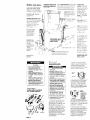
Part No. 3389589 Rev. B
IMPORTANT
Installer: Leave Installation Instructions
with the homeowner
Homeowner:
Keep lnstollatlon Instructions
for future reference.
Save lnstallatlon Instructions for local
electrical
inspector’s use.
I
-
Large Capacity Thin Twin
Washer l Dryer
Four-Wire 240 Volt
Before you start...
b;g;;i
Check
location
where
washer/
dryer will be installed
Proper
lnstollat~on
IS vour resDonslbllitv
Make sure You hove’everythl~g
necessary
for correct
instollatlon
ordinances.
Grounded
IS required
requirements”
zt;g’;n~l
Check
code requirements.
do not permit
or limit the
clothes
dryers I” garages.
moblIe
homes
and
Some codes
installation
of
closels.
quarters
electrical
outlet
(See “Electrlcol
)
Standpipe
drain system
needs
o two-inch
diameter
standplpe
with o m~n~rnum
carry-away
copaclty
of 17 gallons
per
minute
The top of the
stondplpe
must be at least
34 Inches high and no
higher
than 72 Inches
from the floor
Water heater
Set to
d&vcr
140 F
tc
the washer
water
~.
Four-inch
exhaust
required.
metal
duct is
Fire Hazard
. DO Not use or store gasoline,
paint,
thinners
and other
flammable
materials
near
washer/dryer
Fumes from such
materials
could
result in fire or
explosion.
. Never install washer/dryer
up
against
draperies
or curtains
or
on carpet.
To do so may result
in a fire.
. Keep any and all items from
falling
or collechng
behind
the
washer/dryer.
Failure to do so
may result in a fire.
l Replace
all access
panels
before
operaiing
washer/dryer.
Failure to do so may result in a
fire or electrical
shock.
Tools and
materials needed
for installation:
/A
SEE RECESSEDAREA
INSTRUCTIONS ON
BACK COVER.
Level
under
floor: MaxImum
washer:‘dryer
rt Floor must be sturdy enough
o support
washer/dryer
weight
wlIh
water
and clothes
of 500 pounos
Electrical
requirements
Electrical
Shock
Hazard
.Electrical
ground
IS requrred
on
this product
-Improper
connectjon
of the
equipment-groundrng
conduclor
can resull rn electrical
shock
*Check
with a qualrfred
electrician
if you are in doubl
OS to whether
the appliance
is properly
grounded
l Do Not modify the power supply
cord oluo. If it will not fit the outlet.
have.0
Goper
outlet installed
by
a qualified
electrician.
Modifying
the power
supply
cord plug
could
result in electrical
shock
-Use a new JO-ampere
power
supply
cord kit. Do Not reuse an
old power
supply
cord. Possible
electrical
shock
or fire hazard
could
occur
if old power
supply
cord is used.
-Do Not use an extension
cord
with this appliance.
Such use
may result In 0 fire, electric01
shock
or other personal
injury
*Do Nol hove a fuse in the neutral
or grounding
circuit
Thus could
result In electrical
shock.
1 A three-wire.
single phase,
1201
240.volt.
&Hz,
AC only, electrical
supply,
with a fourth
wire OS o
grounding
wire, (or three-wre,
1201
20%volt
electrical
supply with o
fourth wire as o grounding
wire if
specified
on nameplate)
is required
on 0 separate
30.ampere
clrcult.
fused on both sides of the line. The
fourth
(groundIngI
conductor
must
be ldentlfied
by a green
or green1
yellow
cover
and the neutral
conductor
bv o white cover
(Time-delay
fuse or circuit
breaker
is
recommended
)
Panel A
Laundry
system:
tub drown
needs 01 leasi
least 34 nches
hlo”
:no h,gher
lhon 7i
mnches f’orr f,cor
Floor drain system
requires
cz siphon
break,
Part No
285320
ova~lable
from WhIrlpool
outhorlzed
parts
dlstrlbutor
Dryer may be
exhausted
from
the rear or left or
right side
Exhausting
throuqh
the side
requlr&s
Part No
3391335
(See
“Exhaust
requirements’
Panel B )
Protection
from
weather:
Do Not store
or operate
washer/
drver below
32 F (some
waler
may remal”
I”
washer)
Proper
operation
of dryer
cycles
requires
temperatures
above
45 F See Use & Care
Guide
for Wlnterizlng’
information
slope
- 1 Inch
on j
If u longer
droln hose I!
needed
drain hose
Port No 388423
onc
hose extenslo”
kit Port
No 285442 ore
avolloble
f!om
large enougn
so aryer
door co” open fully - c:t
least 90
(See bock
cover
for Recessed
and closet ~nstollatlo”
lnstruct’ons
and
Product
Dimensions’
SEE RECESSED AREA
INSTRUCTIONS ON
BACK COVER.
It is the personal
responslblllty
of the
customer
to contact
o quaIllied
Installer
to assure that the electrlcol
lnstallotlon
IS adequate
and I”
conformance
with the National
ElectrIcal
Code
ANSl/NFPA
70 -latest
edition.
and local codes
and
ordinances
2 This washer/dryer
is equipped
wltk
o 30.amp-rated.
four-wire,
flexibletype. power
supply cord (pigtail)
and o 314”. U L.-listed strain relief.
(See Figure 1 1 Where
local codes
permit,.it
must be plugged
Into o
mating.
30-amp
receptacle
(NEMA
Type 14.30R)
(See figure
2.)
3 IF THE POWER SUPPLY CORD IS
REMOVED.
THE WASHER/DRYER
MUST
BE CONNECTED
WITH lo-GAUGE
MINIMUM,
COPPER WIRE ONLY
(See
Panels F and G ‘“Alternate
electrlcal
connection”,
for detailed
Instructions
)
4 The power
supply cord (pigtall)
co” be removed
and the appliance
con be connected
directly
to a”
Indlvldual.
30.ampere.
fuse or circuit
breaker
box through
flexible.
armored
or non-metallic
sheathed.
lo-gouge
minimum,
copper
cable
It IS the personal
responsibility
and
obligation
of the customer
to
contact
a quaIlfled
electrIcIan
to
OSSUE that the electrical
15 adequate
and IS in conformance
v/lth National
ElectrIcal
Code
ANSl/NFPA
70.latest
edItron.
and
local codes
and ordinances
InstructIons”
on the back
adequate
unobstructed
req”lrements.1
lnstollat~on
Use duel lape
seal all joints.
Allow slack I” the line between
the
wall and the appliance
so that it
con be moved
if servicing
is ever
necessarv
A 3/4”. U L -lIsted stratn
relref must be provided
at each end
of the power
supply cable
(at the
appliance
and at the IunctIon
box)
to
Four-inch,
rigid,
metal
pipe is
preferred
Plan
lnstallatron
to use lhe
of elbows
and turns.
Exhaust aMlow
Frgure
3
5. If you must change
to a
Three-wire.
single phase,
120/240volt, 60-i+.
AC only, electrical
supply
system,
and local codes
permit,
a U.L.-listed.
120/240voll minimum,
JO-ampere,
dryer
power supply
cord kil wilh a
receplocle
of NEMA Type IO-30R
may be used.
(See Figure 3.) This
cord must contain
three.
No.-10
copper
conductors
with ring
terminals
or spade
terminals
with
upturned
ends on the washer/dryer
end. Where local codes permit.
it
must be plugged
Into a mating
30.
amp receptacle
(NEMA type
lo-30R).
Cord should be Type SRD or
SRDT and be at leost four feet long
The three-wire
power
supply
cord IS
not provided
with the washer/dryer.
A kit, Part No. 687104. IS available
from your WhIrlpool
dealer.
NOTE: If local codes requrre
permanently
connected
wiring,
“Alternate
electrlcol
connection”.
Panels F and G.
fewest
II the washer/dryer
is installed
in a
confined
area such as a bedroom,
bathroom,
or closel.
it must be
exhausted
to the outsrde
and
provrsron
must be made
for enough
air for combustion
and ventilation.
Check
governrng
codes
and
ordinances.
Also refer to the
Recessed
and
closet rnstollation
Instructions
on
the back cover.
number
Exhaurl Oi”,OW
An exhaust
hood
should
cap the
exhaust
duct to
prevent
exhausted
air from returning
into the dryer.
The
outlet
of the hood must be ut least
12’ from the ground
or any object
that may be in the path of the
exhaust.
Metal.
flexible
duct must be fully
extended
and supported
when
the
dryer is in its frnal position.
DO NOT
KINK OR CRUSH THE DUCT. The
metal
flexible
duct must be
completely
open to allow adequate
exhaust
air to flow
a-inch
outlet hood is preferred.
However,
a 2-l/2
inch outlet
exhaust
hood may be used A 2-l /2 Inch
outlet
creates
greater
back pressure
than other hood types.
Allow as much
room as possible
usmg
elbows
or making
turns.
when
Bend duct gradually
to avoid
kinking.
Remove
excess, flexible
duct
to avoid
sagging
and klnklno
thai
m-l
may resultln
reduced
alrflow.
The exhaust
duct
Space
requirements
are provided
the back cover
of Installation
Instructions
and on the rear panel
the washer/dryer.
on
of
Maximum
length
of the exhaust
system depends
upon the type of
duct used. number
of elbows
and
the type of exhaust
hood.
The
maximum
length
for both rigrd and
flexible
duct is shown
I” chart
Exhaust
requirements
- Check
Ihat exhaust
system
is
not longer
lhon spectfied.
Exhaust
systems
longer
than
specrlied
will:
Accumulate
lint.
Shorten
the life of the product.
Reduce
performance.
Result in
longer
drying
times and
increase
energy
usage.
Failure to follow specificolrons
may result In 0 fire.
. Do Not exhaust
dryer into 0
chimney,
furnace
cold oil duct.
attic or crawl
space,
or ony
other duct used for venting.
. Clean
the exhaust
system
every
other yeor.
- Do Not Install flexible
duel under
wall,
celling
or floor materlols
Panel
B
Fire Hozard
Exhausting
your dryer indoors
iS
nol recommended.
The moisture
and lint indoors
moy cause:
. FIRE HAZARD from lint collected
in dryer;
. Morsture
damage
to woodwork,
lurniture,
point, wallpaper,
carpet.
etc.;
. House-cleaning
problems
and
possible
health
problems.
Follure lo follow the above
precaution
could
result in fire.
personal
rnjury or property
domoge.
Fire Hazard
. Do Nol use non-metal,
flexible
duel.
. Do Not use metal duct smaller
than four inches
I” diameter.
- Do Not use exhaust
hoods with
mognetrc
latches.
Improper
crir supply
for exhausting
moy result In a fire.
lent could result
moisture
domage.
Exhausting
the
dryer through
the side of the
washer/dryer
requires
the
use of Side
Exhaust.
Part
No. 3391335.
Follow kit
installation
Instructions
for
proper
exhaust
installation.
see
To convert
to three-wire
electrlcal
system,
the four-wve
power
supply
cord must be removed
and the
appliance
cabinet
must be
grounded
according
to local codes
either by “sing the neutral
terminal
or a separate
grounding
wire. (See
Panel F, “Alternate
electrical
connectton”,
for detolled
irstructions
1
Accumulaled
fire or cause
co”or
for
afr opening
in o
Mobile
For exhausl
ryslems
not covered
by
the exhaust
length
char-t. see
&hlrlo00l
Service
‘Exhausting
Whirlpool
Dry&s.’
Part
No. 603197, available
from your
Whirlpool
parts distributor.
Service
check:
The back pressure
in
any exhaust
system used must not
exceed
0 6 inches of water
column
measured
with an rncllne
manometer
at the point that the
exhaust
duct connects
to the dryer.
Exhausting
the dryer outside
is
recommended.
A closet instollotlon
m!&l be exhausted
outside.
Recessed
installatron
that is not
exhausted
outside
must use Exhaust
Deflector
Part No. 694609 available
from your Whrrlpool
dealer.
(See
“Recessed
and closet installation
Home Installation
This appliance
is suitable
for mobile
home
installations.
The installation
of the washer/dryer
must conform
to
the Manufactured
Home Construction
and Safety Standard.
Title 24 CFR, Part
3280 (formerly
the
\
81
Federal
Standard
for Mobrle
Homes
Construction
and
1i
I
Safety.
Title 24,
I
HUD Part 280.
1975) or latest
d
edition.
Ii
Mobile
home exhaust
The washer/dryer
must
outside
exhaust.
If the
exhausted
through
the
area under
the mobile
enclosed,
the exhaust
terminate
outside
the
area
Extension
beyond
enclosure
will prevent
moisture
buildup
under
home.
requirements:
have an
dryer is
floor and the
home
is
system must
enclosed
the
lint and
the mobile
Now start...
with
washer/dryer
in laundry
6.
area
Slide nozzle end
of dram hose
through
the small
“loop”
in the wire
form
Wrap the
hook end of the
wrre form around
the drain hose to
form a ‘hook”
shape
Personal
Injury Hazard
More than one person
is required
to lift, tilt or move the washer/dryer
because
of its weight
and size.
Failure to follow these instruchons
may result in personal
inlury.
Truck only from the rear
product
damage.
to prevent
3
t-.
/”,
I,
1
Pull the yellow
shlpping
strap
completely
out of the washer/dryer,
Remove
the label that
covers
the Yellow Shipping
strap.
Pull to completely
remove
the
shrpping
strap from the inside of the
washer/dryer
Do Not force excess
length
hose down the standpipe.
could
cause siphoning.
n
Use new hoses and washers
came
with your washer/dryer.
of drain
This
that
Open washer
Ird Take hoses
and parts packages
out of
Close lid
n
basket.
coupling
washer
4
Insert a flat washer
into
n
each end of the Inlet hoses
Check
that washers
are firmly seated
rn couplings
vu
/
Inlet VdWS
1
are plarlic.
7
i
DO Nor srrrp o,
1 hose clamp
I wire form
4 flat. water-hose
. 1 grounding
wire
l
I
l
l
2
parts
n
washers
assembly
Remove
parts from
package.
Check
that
were included.
all
3-Attach
one hose
1-L
to the bottom
inlet
kvalve
Then attach
the second
hose to the top inlet
valve.
Tighten
couplrngs
by hand,
then use pliers to make an additional
two-thirds
turn
-
Put “hook”
end of drain
H
hose into laundry
tub or
standpipe.
Estimate
length
of dram
hose needed
when
washer/dryer
is
If the drain hose is
in final position
too long-remove
clamp
and
coupling:
cut flexible
end of hose
(Do Not cut hook-shaped
end of
drown hose.)
Push and twist coupling
securely
onto drain nose.
(You
should feel top of dram hose through
coupling.)
Slide clama
over
couplrng
and hose
9.
17.
Pull yellow
shipprng
strop
with 3 cotterpins
completely
out of
washer/dryer.
Install wire form
on drain hose.
6. 16.
10.
Numbers
correspond
to steps.
Panel
C
8
Place hose clamp
over
n
washer
drain connector
Push couplrng
end of drain hose on
to washer
connector.
Use pliers to
open clamp
and slrde clamp
over
drain hose
Check
for good fit
Insert corner
posts or other type of
support
6 inches
from left leg.
Do Not insert corner
aosts in the
center
of the washer>drYer
14
Floor Domoge
Slide washer/dryer
onlo
cordboord
or hordboard
before
moving
across floor.
Failure to do
so may cause
damage
to floor
covering.
9
If you have room to work
.
from either side of the
washer/dryer,
move washer/dryer
close to final positron
so you can
easily complete
the followrng
steps
Go to Step 10
It you are working
in a closet or
recessed
area, move the washer/
dryer into its final positron
and
remove
cardboard
or hardboard
from under washer/dryer.
Remove
access
panel
by removing
three
PhIllips-head
screws and one
bumper,
located
at the top of the
access
panel.
Set panel,
screws
and bumoer
aside.
(See Steo 17.
Panel D.) Complete
ihe folIowIng
steos through
the access
area
If it is not level, carefully
tilt
n washerldrver
backward
until front of washer/dryer
is 3-4
Inches off of the floor
Insert 4 corner
posts under washer/dryer
about
SIX
Inches from the left leg
Loosen nuts
on each front leg
Adyst
the front
legs up or down
Tilt washer/dryer
backward
and remove
corner
posts
Gently
lower the washer/dryer
to the
floor Repeat
Step 13 If It is stall not
level, repeat
Step 14 and then Step
13 until washeridrver
is level
17
If you did not remove
n access
panel
in Step
do so by removing
three Phrllipshead screws and one bumper.
located
at the top of the access
panel.
Set panel.
screws and
bumper
aside.
18
Determine
the length
of
n exhaust
duct that is
needed
to connect
the dryer to the
exhaust
hood.
(See “Exhaust
requirements*,
Panel 8.) Connect
the exhaust
duct to the washer/
&vda and then to the exhaust
\
15
When washer/dryer
IS
n level. use wrench
to turn
nits on front legs up tightly
against
washer/dryer
base.
If nuts are not
tight against
washer/dryer
base, the
washer/dryer
may vibrate.
10
20
Before attaching
water
Inlet hoses
run water
through
both faucets
Into
a bucket
Thus will aet rid of oatircles
In the water
lanes t<at might’clog
the noses
21
Put the “hook”
end ot
m the dram hose back rn
the laundry
tub or standprpe
Check
for proper
lenath
of dram
hose
If drain hose IS ibo long.
disconnect
and repeat
Steps 7
and 0.
CHECK ELECTRICAL
REQUIREMENTS.
BE SURE
YOU HAVE CORRECT ELECTRICAL
SUPPLY AND RECOMMENDED
GROUNDING
METHOD.
Check
the
Installation
lnstructrons
to see that
YOU have CornDIeted
each
step.
Complete
any mrssed steps before
you continue
Attach
bottom
hose
m (inlet marked
“H”) to hot
water
faucet.
Attach
top hose
(Inlet marked
“C”) to cold water
faucet.
Tighten
the coupling
to the
faucet
by hand
Use plrers to make
fina two-thrrds
turn
CHECK THAT
HOSE IS NOT
TWISTED OR
KINKED AND
to its permanent
cordboord
from
Note:
hose.
13
Tilt washer/dryer
forward
E ralsrng back legs I” off of
floor to automatrcallv
adjust rear
self-levelrng
legs. Gently
lower
washerldrver
to floor.
Check
levelness
of the washer/dryer
bv
placrng
a carpenter’s
level on top
Of the washer,
first side to stde. then
froni to back
If washer/drver.is
leve
QO to Step 15
Panel
D
n
Check
that all parts are
n now installed.
(See
parts Ikst. Panel C.) If there is an
extra part. QO back through
steps to
see which
step was skipped.
12
Move washer/dryer
location.
Remove
under wosherldrver.
the
9.
agan.
rZI=Z
If washer/dryer
is moved
lo odiurl
the washer dryer musl be leveled
drain
Pepear srepr 13-1s.
16
Secure
drain hose to tub
n or standoroe
bv wraobina
the plastic
strap arou’nd
the hose asshown
in Figures A-C.
If drain hose
cannot
be strapped
s-i place.
rt must
be cut exactly
to length
so that the
-hook”
end is held tightly
over the
edge
of the tub or standpipe
as
shown
In Frgure D.
22
11
Check
that you
n removed
all the shlpprng
pieces,
including
the yellow.
shipping
Strap with Its 3 Cotterpins.
Drspose of all materials
rn the proper
manner.
If You do not remove
the Yellow,
shipping
strap, Your washer/dryer
may “walk”
away
from Its location.
If washer/drver
does not
operate pioberly...
Check
the follow~na
I Electrical
supply;
2 House fuse or clrcwt
Intact
and tight
3 Washer
lid or dryer
4 Controls
are set r
“ON” posItIon.
5 Dryer “startbutton
firmly pushed
6 Make sure yellow,
has been completely
23
24
Check
of your
.
that you
tools
have
all
Turn on the water
n faucets
and check
fol
leals
Tlghte”
the couplings
if there
IS le IkIng
25
Replace
the access
n panel
Be s”re to tlghten
screws at each
end ol the access
par el Replace
the bumper
under
the zenter
screw and tighten
the
cer ter screw
26
Read the Use and Care
G&k
to fully
uncarstond
your new washer/dryer
WICZ out the drum
Plus the
electrical
cord Into a grounded
out ?t Now start the washer
and
alloti
It to complete
the regular
cyi le.
27
n
Open the dryer door
Check
to be sure the
iin, ;creen
15 in IiS proper
position
Sto t the dryer and allow It to
cor@ete
a cycle to make sure It IS
wor*lng
properly.
28
with
Panel
n
FInally. save all
.
literature
and keep
the washer/dryer
E
It
to be sure that
connected
breaker
IS
door IS closed
a running
or
has been
shipping
strap
removed
Dwng
normal
bwness
hours the
Whlrlaool
COOL-LINE’
Service
~111
answer
any questIons
about
operotlng
or molntolnlng
your
washer/dryer
not covered
In your
lnstallat~on
lnstructlons
The
Whirlpool
COOL-LINE’
Service
number
is (800) 253-1301
Dial Just as
you normally
dial long distance
the co!1 1s free
Alternate electrical
connection
Elechical
Shock Hazard
- Electrical
ground
is required
on
lhis appliance.
- Improper
conneclion
of Ihe
equipment-grounding
conductor
line con result in
electrical
shock.
- Check
with a qualified
eleClliCian
if you are in doubt
as lo whether
the appliance
IS
properly
grounded.
* Do Nof modify
Ihe power
supply
cord plug.
If it will nol fit
the outlet.
have o proper
outlet
installed
by a qualified
electrician.
Modifying
the
power
SUPPIY
cord plus could
resull in &cirical
shoci.
-Use a new 30-ampere
power
supply
cord kit. Do Nofreuse
an
old power
supply
cord. Possible
elecfricol
shock or fire hazard
could
occur
if old power
supply
cord
Thls appliance
is manufactured
with
a 30 amp rated, four-wire,
llexible
type power
supply
cord with the
green grounding
wire connected
to
the grounding
connector.
To connect a
separate grounding
wire -
Use grounding
wire and clamp
assembly
(Part No. 685463) or No.-10
gauge
minimum.
copper,
groundrng
wire
Panel
F
Permit four-wire
copper
power
supply
cable
and
Permit connecting
cabinetgrounding
conductor
to the neutral
wire of the power
supply
cable,
Center.
rllvel-colored
terminal block screw
and neutral while wire
\
10
lnlernal
rounding
wire
(green wR h yellow stripa&)
To convert to a
three-wire
electrical system.
When local codes...
A.
Permit use of a flexible-type
power
supply
cord (pigtail)
plugged
into a
matching,
30-amp
receptacle
(See
“Electrical
requirements”.
Panels A
and B) and
Permit connection
of the
internal
grounding
conductor
to the
neutral
wire of the power
supply
cord:
cenlel.
lnlelnal
ril”el-cololed.
ungrounded
Figure
gro”nd,nQ
wire (green w”h
yellow
alrIper)
lerminal
block zrew
and neulral
whHe wire
Four-wrre
is used.
- Disconnect
the power
supply
cord from the electric
supply
before
making
these changes,
Failure to do so may result rn
personal
injury.
:ailure
lo follow these inslruclions
zould result in electrical
shock.
Figure
When local codes...
Do Not Permit the use of the flexible
four-wire
power
supply cord that
comes
equipped
with the washer/
dryer and
neutral
4
1. Disconnect
the power
supply.
2. Remove
the power
cord
equipped
with the washer/dryer
as
instructed.
See “To remove
power
supply
cord.”
Panel F
3 Install copper
four-wire
Dower
supply cable
through
the j/4”.
U L.-lrsted strain relief (See “Electrical
Requirements”,
Panels A and B)
4. Connect
the grounding
wire.(bare
copper.
green or green with yellow
stripes) of the copper.
four-wire
Power
supply cable
to the external
grounding
connector
5. Connect
the neutral
wire (white)
of the power
supply cable
and
Internal
grounding
wire (green
with
yellow
stripes) to the center,
sliver-colored.
terminal
screw of the
terminal
block.
Connect
the other
wires to the outer terminals.
Tighten
each screw firmly See Figure 4. nor
plain-end
wires, see ‘Direct
wiring
COnneCtiOn,.
Panel G.
6. Replace
the terminal
block cover.
Connect
grounding
wire to a
grounded,
cold water
pipe’
with the
clamp
and then to the grounding
connector
on the washerldrver.
Do
Not ground
to a gas supply
plpe orhot water
pipe.
Do Not connect
the
power
supply
cord to electric
power
supply
until the appliance
is
permanently
grounded.
Grounded
Figure
neutral
5
1. Disconnect
the power
supply.
2 Remove
the power
supply
cord
equipped
with the washer/dryer
as
instructed.
See Panel F. “To remove
the power
supply
cord”
3. Install a three-wrre
power
supply
cord (See “Electrical
requirements”,
Panel A and B) through
the 3/4’,
IJ L.-listed strain relief.
4. Move the internal
grounding
wire
(green
with yellow
stripes) from
the center,
silver-colored
terminal
block screw to the external
grounding
connector.
5. Connect
the neutral
wire (white)
of the power
supply cord to the
center,
silver-colored.
terminal
screw
of the terminal
block.
Connect
the other wires to the outer
terminals
Tiahten each screw firmlv
See Figure 5: For plain-end
wires. ;ee
‘Direct
wiring
connection.’
Panel G.
6 Replace
the terminal
block cover.
To remove the
rtr;er - SUPPlY
1 .Dlsconnect
the power
supply.
2. Remove
the terminal
block cover
from the dryer.
3. Disconnect
the power
supply
cord
from the terminal
block.
4. Disconnect
the green,
grounding
wire of the power
supply
cord from
the external
grounding
connector.
5. Loosen the strain relief screws.
6. Pull downward
on the power
supply cord until it is removed
from
the dryer.
(See Figure 11.)
When local codes..
When local codes...
When
B.
c.
D
Permit
power
the use of a flexible-type
supply
cord (pigtail)
but
Do Nol permrt connecting
cabrnetgrounding
conductor
to the neutral
wire of the power
supply cord:
Do Not permit
the
three-wne,
power
Permit three-wire.
supply cable
and
Permit connecting
grounding
conductor
w!re of the power
use of a flexible.
supply
cord and
copper
power
the
cabinetto the neutral
supply
cable:
tnternat grounding
wire (green with
yellow rlrip%r)
center.
silver-colored.
,*,mtnat
block screw
and neutral white wile
\
Ungrounded
Sepmate
copper
grounding
\ wtre
6
Cente,.
rllver-colored.
terminal
block screw
and neutral while wtre
Internal
groundtng
wtre (green with
yellow
stripes)
\
Ungrounded
Connect
seporole.
copper
grounding
wire (No.-10
minimum)
from external
grounding
connector
to approved
ground.
I, Disconnect
Ihe power
supply.
2. Remove
the power
supply
cord
equipped
with the washer/dryer
as
instructed.
See Panel F, “To remove
the power
supply cord ”
3. Install a three-wire
power
supply
cord (See “Electrical
Requirements”,
Panels A and B) through
the 314’.
U.L -lIsted strain relief
4. Connect
the neutral
wire (white)
of the power
supply cord and the
internal
grounding
wire (green
with
yellow
stripes) to the center.
slivercolored,
terminal
screw of the
terminal
block
Connect
the other
wires to the outer terminals.Tighten
screws firmly (See Figure 6 1 For
@an-end
wares, see‘To
connect
connection:
Panel G.
5 Connect
a separate
copper
grounding
wire (No. IO minimum)
See “To connect
a separate
grounding
wIrerPanel
F for
detolled
Instructions.
6. Replace
the terminal
block cover.
Direct wiring
connection
1. Disconnect
the power
supply.
2 Strip the outer covering
back 3
inches from the end exposing
the
three wires.
-II
ps-4
-il’t
Plain-endwirlng
Figure 12
i
3. Srrlp the Insulation
back
1 inch
from the end of each wire.
Form
the bare wires into a “U”-shaped
hook.
4. Loosen.
Do Not remove.
screws
from terminal
block.
Attach
wires
according
to instructions
for type of
connection
needed
5. Slide the end of each wire under
the screw head with the open side
of the screw hook on the right.
Squeeze
the wire together
to form a
loop.
6 Tighten
each screw firmly.
7. Tlghten
strain relief screws.
Panel G
n
Do Not oermit
the use of three-wire.
flex!bie.‘power
supply
cord and
Permit three-wire.
copper
Power
supply cable
but
Do Not permit
connecting
the
cabinet-grounding
conductor
to
the neutral
wire of the power
supply
cable:
neutral
Figure
LIZ
local codes...
Grounded
Figure
Figure
neutral
7
I. Disconnect
the power
supply
cord.
2 Remove
the power
supply
cord
equipped
with the washer/dryer
as
Instructed.
See “To remove
the
power
supply
cord-.
Panel F.
3. Install copper
power
supply cable
(See “Electrical
requirements”.
Panels A and 8) through
the 3/4’.
U./L.-listed
strain relief.
4 Move
the internal
grounding
wire
tareen
with vellow
stripes) from
i6e center,
s&er-colo;ed.
terminal
block screw to the external
grounding
connector.
5 Connect
the neutral
wire (white)
of the flexible,
armored
or
non-metallic
sheathed,
cooper.
cable
to the center.
power
supply
silver-colored,
terminal
screw of the
terminal
block.
Connect
the other
wires to the outer terminalsTighten
the screws firmly
See Figure 7. For
plain-end
wires, see “To connect
connection.’
Panel G.
6. Replace
the terminal
block cover.
neutral
8
Connect
saparale,
copper
grounding
wire (No.-10
minimum)
from external
grounding
connector
to approved
ground.
1, Disconnect
the power
supply.
2. Remove
the power
supply
cord
equipped
with the washer/dryer
as
Instructed.
See “To remove
the
power
supply
cord”,
Panel F.
3 Install copper
power
supply
cable
(See “Electrical
requirements”.
Panels A and B) through
the 3/4’.
U.L.-listed
strain relief.
4 Connect
the neutral
wire (white)
of the flexible,
armored
or
non-metallic
sheathed.
copper.
power
supply
cable
and the internal
grounding
wire (green
with yellow
strrpes) to the center,
silver-colored.
terminal
screw of the terminal
block.
Connect
the other wires to the outer
terminals,
Tighten screws firmly. (See
Fiaure 8.1 For olain-end
wires. see
“Direct
wiring
cOnneC~lOn.~
Panel G.
5. Connect
a separate.
copper.
grounding
wire (No.-10
minimum).
See ‘~To connect
a separate
grounding
wire’
, Panel F. for
detailed
Instructions.
6 Replace
the terminal
block cover.
V~
Recessed and closet
installation instructions
Product dimensions
Recessed nonexhausted
installation
must use only the rear exhaust
aosition and Exhaust Deflector.
Part
3’
l!!t
k
26-1/4--j
ido. 694609.
l
l
Fire Hazard
The dryer should be exhausted
outside. Failure to do so
increases the risk of fire.
If washer/dryer
is installed in a
closet, the dryer MUST be
exhausted
outside. Failure to do
so may cause a fire.
This washer/dryer
may be installed
a recessed area or closet.
in
The installation spacing is in inches
and is minimum allowable.
Additional
spacing should be
considered
for ease of installation,
servicing and’compliance
with local
codes and ordinances.
If closet door is installed, the
minimum unobstructed
air openings
in top and bottom is required.
Louvered doors with equivalent
air
openings are acceptable.
Closet
btallation
must be exhausted.
VkW
Recessed
minimum
installation
spa&Q.
Nate: tt recessed
Installation
is exhausted
to
the side or rear, 6 inches
musl be avallable
above
the washer/dryer
but all other spacing
can be 0 inches.
Cl$ses.etptallatton
mud
be exhausted
Closet
Door
48 sq.
Other installations must use the
minimum dimensions indicated.
To prevent large amounts of lint and
moisture from accumulating
and to
maintain drying efficiency,
this
appliance
should be exhausted
outdoors.
area
1
t
Exhaust
24 sq.
Side
VIW
r
Front
Vlew
CORPORATION
Port No 3389589
:c- 1990 Whfrlpool
Rev B
Corporal~on
Prepared
by WhIrlpool
Corporation.
Benton
Harbor,
Michlgon
49022
Pmted
in U S A