1
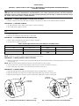
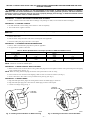
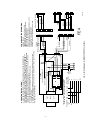
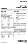
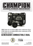
Installation Instructions
Manufactured Housing
Blower Control Box
for Electric Furnaces
KMACC0401E14
KMACC0601FE4
NOTE: Read the entire instruction manual before starting the installation.
SAFETY CONSIDERATIONS
Improper installation, adjustment, alteration, service, maintenance, or use can cause explosion, fire, electrical shock, or other conditions which may
cause personal injury or property damage. Consult a qualified installer, service agency, or your distributor or branch for information or assistance.
The qualified installer or agency must use factory-authorized kits or accessories when modifying this product. Refer to the individual instructions
packaged with the kits or accessories when installing.
Follow all safety codes. Wear safety glasses and work gloves. Use quenching cloth for brazing operations. Have fire extinguisher available. Read
these instructions thoroughly and follow all warnings or cautions attached to the unit. Consult local building codes and National Electrical Code
(NEC) for special requirements.
. When you see this symbol on the unit and in instructions or manuals, be alert
Recognize safety information. This is the safety-alert symbol
to the potential for personal injury.
Understand the signal words DANGER, WARNING, and CAUTION. These words are used with the safety-alert symbol. DANGER identifies the
most serious hazards which will result in severe personal injury or death. WARNING signifies hazards which could result in personal injury or
death. CAUTION is used to identify unsafe practices which would result in minor personal injury or product and property damage.
WARNING: Before installing or servicing system, always turn off all power to unit. There may be more than 1
disconnect switch. Turn off accessory heater power if applicable. Electrical shock can cause personal injury or death.
INTRODUCTION
This instruction covers the installation of blower control box kit Part No. KMACC0401E14 and KMACC0601FE4. These kits are designed to add
cooling controls to Nordyne/Miller/Intertherm Electric Furnaces using the existing multi-speed furnace blower. These kits will not work with
heating-only blowers. These kits are designed for installation with a 4-wire heating/cooling thermostat.
These kits is designed to work with the electric furnaces listed below. When using the existing furnace blower in some applications, the resulting
airflow may be too low. A blower change out is recommended in any application which results in less than 350 CFM/12,000 Btuh. Blower
packages KMABA03013TE, KMABA04014TE, KMABA05013TE, and KMABA06014TE are available if blower changeout is required.
Kit Part No. KMACC0401E14 is for use with Nordyne/Miller/Intertherm E1EH Electric Furnaces. Kit Part No. KMACC0601FE4 is for use with
Nordyne/Miller/Intertherm FEHB, FEBB, and E1EH Electric Furnaces. Refer to Table 1 for kit contents. Refer to the appropriate section for your
furnace and control kit.
• Section 1—Installation of Kit Part No. KMACC0401E14 in Nordyne/Miller/Intertherm E1EH Electric Furnaces
• Section 2—Installation of Kit Part No. KMACC0601FE4 in Nordyne/Miller/Intertherm FEHB and FEBB Electric Furnaces
Table 1—Kit Contents
QUANTITY
DESCRIPTION
KMACC0401E14
1
2
—
1
Control Box
No. 10 X 1/2-in. Screw
Accessory Wire Harness
Installation Instructions
Form:
AG-MACC-01
Cancels:
AG-SACC-01, -02
Printed in U.S.A.
KMACC0601FE4
1
2
2
1
5-97
Catalog No.
92-33MA-CC1
INSTALLATION
SECTION 1—INSTALLATION OF KIT PART NO. KMACC0401E14 IN NORDYNE/MILLER/INTERTHERM E1EH
ELECTRIC FURNACES
WARNING: For safe operation, it is the responsibility of the installer to assure that this package is installed in
accordance with the furnace manufacturer’s recommendations, local codes, good trade practices, and these Installation
Instructions. Failure to follow this warning may result in property damage, personal injury, or death form hazards such as
fire, smoke, soot, electric shock, or carbon monoxide.
PROCEDURE 1—UNPACK AND INSPECT CONTROL BOX KIT PARTS
1. Remove control box from carton and check for damage. If any damage is visible, do not install. File claim with shipper.
PROCEDURE 2—PREPARE FURNACE
1. Set wall thermostat to lowest setting. Allow furnace to shut off completely.
2. Turn off all electric supplies to furnace.
CAUTION: Furnace may be connected to more than 1 power supply.
3. Remove furnace door.
4. Disconnect the multi-point plug from furnace control panel.
PROCEDURE 3—DETERMINE PROPER BLOWER SPEED
1. Refer to Table 2 and determine proper blower speed for application.
2. Set proper blower speed in control box.
Table 2—Blower Speed Selection for Proper Operation of E1EH Furnaces
HEATING
Furnace Heating
(kW)
10—12
15—23
COOLING
Capacity
(Btuh)
24,000
30,000
36,000
Heating Speed
LOW
HIGH
Cooling Speed
LOW
HIGH
NOTE: Control box is wired for medium speed heating and high speed cooling.
PROCEDURE 4—MOUNT CONTROL BOX ON BLOWER
1. Mount control box base on furnace blower casing where male plug will reach receptacle in furnace control panel using the 2 screws provided
in kit. (See Fig. 1.)
NOTE: Make sure wiring harness will plug into furnace control panel with no strain on wiring.
2. Insert control box onto control box base aligning 2 holes in sides of control box and base. (See Fig. 2.)
3. Secure control box to base with 2 screws removed from control box. (See Fig. 2.)
PROCEDURE 5—MODIFY WIRING
1. Plug male multi-point motor plug from existing furnace blower into female plug in control box.
2. Plug male inline plug from control box into high-voltage inline female plug on furnace control panel.
3. Plug male matrix plug from control box into low-voltage matrix female plug on furnace control panel.
CONTROL
BOX BASE
BLOWER
CONTROL
BOX
CONTROL
BOX BASE
A96581
A96577
Fig. 1—Installing Control Box Base on Blower Housing
Fig. 2—Attaching Control Box to Control Box Base
—2—
OPERATION INSTRUCTIONS:
A. BLOWER IS SUPPLIED WITH HEATING TERMINAL #5 ON THE BLOWER RELAY
JUMPERED TO TERMINAL #2 HIGH SPEED. REMOVE AND INSTALL RED LOW SPEED
LEAD ON 010KW AND 12KW FURNANCES.
B. A FILTER IS REQUIRED TO PREVENT LINT AND DUST FROM
PLUGGING THE COIL.
C. CHECK FOR CORRECT BLOWER OPERATION ON BOTH HEATING AND COOLING.
D. IF ANY OF THE ORIGINAL WIRE, AS SUPPLIED, MUST BE REPLACED, USE THE SAME
OR EQUIVALENT TYPE WIRE.
BLOWER
RELAY
RED
BLACK
BLUE
1
2
3
4
5
6
5
2
3
6
4
WHITE
WHITE
1
MOTOR
PLUG
RED
YELLOW
BLACK
RED
WHITE
GREEN
YELLOW
6
5
4
3
2
1
HIGH
VOLTAGE
PLUG
1
2
3
4
5
6
LOW
VOLTAGE
PLUG
E1-4
TO COND
UNIT
Y
G
HEAT COOL
R W TSTAT TERM
A96584
Fig. 3—Wiring Diagram for KMACC0401E14 Control Box
4. Connect low-voltage wiring per Fig. 3.
PROCEDURE 6—REASSEMBLE FURNACE AND CHECK FURNACE OPERATION
1. Reinstall furnace door.
2. Turn on electric supplies to furnace.
3. Observe system operation in cooling and heating modes to ensure system is in a safe, reliable operating condition.
—3—
SECTION 2—INSTALLATION OF KIT PART NO. KMACC0601FE4 IN NORDYNE/MILLER/INTERTHERM FEHB AND FEBB
ELECTRIC FURNACES
WARNING: For safe operation, it is the responsibility of the installer to assure that this package is installed in
accordance with the furnace manufacturer’s recommendations, local codes, good trade practices, and these Installation
Instructions. Failure to follow this warning may result in property damage, personal injury, or death form hazards such as
fire, smoke, soot, electric shock, or carbon monoxide.
PROCEDURE 1—UNPACK AND INSPECT CONTROL BOX KIT PARTS
1. Remove control box from carton and check for damage. If any damage is visible, do not install. File claim with shipper.
PROCEDURE 2—PREPARE FURNACE
1. Set wall thermostat to lowest setting. Allow furnace to shut off completely.
2. Turn off all electric supplies to furnace.
CAUTION: Furnace may be connected to more than 1 power supply. Do not use factory circuit breaker as a
disconnect.
3. Remove furnace door.
4. Pull out furnace safety disconnect from furnace control panel where applicable.
5. Disconnect multi-point plug from furnace control panel.
PROCEDURE 3—DETERMINE PROPER BLOWER SPEED
1. Refer to Table 3 and determine proper blower speed for application.
2. Set proper blower speed in control box.
Table 3—Blower Speed Selection for Proper Operation of FEHB and FEBB Furnaces
HEATING
COOLING
Furnace Heating
(kW)
10—17
Capacity
(Btuh)
24,000
30,000
36,000
Heating Speed
LOW
20—24
HIGH
Cooling Speed
LOW
HIGH
NOTE: Control box is wired for medium speed.
PROCEDURE 4—MOUNT CONTROL BOX ON BLOWER
1. Mount control box base on furnace blower casing where male plug will reach receptacle in furnace control panel using the 2 self-tapping
screws provided in kit. (See Fig. 4.)
NOTE: Make sure wiring harness will plug into furnace control panel with no strain on wiring.
2. Insert control box onto control box base aligning 2 holes in sides of control box and base. (See Fig. 5.)
3. Secure control box to base with 2 screws provided in loose parts bag. (See Fig. 5.)
PROCEDURE 5—MODIFY WIRING
1. Plug male multi-point motor plug from existing furnace blower into female plug in control box
2. Plug male multi-point plug from control box into female plug on furnace control panel.
3. Connect low-voltage wiring per Fig. 6.
CONTROL
BOX BASE
BLOWER
CONTROL
BOX
CONTROL
BOX BASE
A96581
A96577
Fig. 4—Installing Control Box Base on Blower Housing
Fig. 5—Attaching Control Box to Control Box Base
—4—
BLUE
SEC
PRI
3
1
BR
6
5
MED HI SPD
4
2
C
Y
C
Y
W2
O
O
TO
COND
UNIT
WHITE
BLACK
RED
GREEN
MED LO SPD
HI SPD
Y R G W
WHITE
RED
1
2
3
4
5
6
7
8
9
10
11
12
1
2
3
4
5
6
7
8
9
10
11
12
FE4
1
2
3
4
BLACK
5
WHITE
6
7
WHITE
8
9
YELLOW
10
11
12
RED
BLACK
Fig. 6—Wiring Diagram for KMACC0601FE4 Control Box
HEAT PUMP
THERMOSTAT
R
G
RED YEL WHT GRN
W2
OUTDOOR
UNIT
R
TYPICAL LOW VOLTAGE HEAT PUMP WIRING
BLOWER LOW VOLTAGE CONNECTIONS
24V
40VA
240V
LO SPD
COVERED TERMINALS
1
2
3
4
5
6
7
8
9
10
11
12
BLACK
RED
WHITE
BLACK
ORANGE
RED
YELLOW
ORANGE
YELLOW
RED
1
2
3
4
5
6
1
2
3
4
5
6
A97158
WHITE 1
2
3
4
5
6
E1EH ADAPTER PLUGS
HEATING SPEED
FEHB/FEBB 10H-17H HEATING SPD LO
FEHB/FEBB 20H-24H HEATING SPD MED LO
E1EH 10H-12H HEATING SPD LO
E1EH 15H-24H HEATING SPD HI
CONTROL BOX HEATING WIRED FOR MED LO SPD
COIL CAPACITY COOLING SPEED
24,000 BTU/LO - 30/36,000 BTU HI
CONTROL BOX COOLING WIRED FOR HI SPD
YELLOW
RED
GREEN
YELLOW
RED
BLUE
FOR NORDYNE FEHB/FEBB/E1EH
OPERATION INSTRUCTIONS:
A. BLOWER IS SUPPLIED WITH HEATING TERMINAL #5 ON THE BLOWER RELAY
CONNECTED TO MED LO SPEED MOTOR LEAD (RED) AND COOLING TERMINAL #2
TO HIGH SPEED MOTOR LEAD (BLACK). CHANGE MOTOR LEADS TO PROVIDE
PROPER BLOWER SPEED FOR FURNACE AND COIL CAPACITIES AS RECOMMENDED
IN BLOWER SPEED SELECTION CHART. WHEN HEATING AND COOLING SPEEDS
ARE THE SAME, CONNECT #5 AND #2 TERMINALS.
B. A FILTER IS REQUIRED TO PREVENT LINT AND DUST FROM
PLUGGING THE COIL.
C. CHECK FOR CORRECT BLOWER OPERATION ON BOTH HEATING AND COOLING.
D. IF ANY OF THE ORIGINAL WIRE, AS SUPPLIED, MUST BE REPLACED, USE THE SAME
OR EQUIVALENT TYPE WIRE.
WHITE
—5—
PROCEDURE 6—REASSEMBLE FURNACE AND CHECK FURNACE OPERATION
1. Reinstall furnace door.
2. Turn on electric supplies to furnace.
3. Observe system operation in cooling and heating modes to ensure system is in a safe, reliable operating condition.
—6—
—7—
SERVICE TRAINING
Packaged Service Training programs are an excellent way to increase your
knowledge of the equipment discussed in this manual, including:
• Unit Familiarization
• Maintenance
• Installation Overview
• Operating Sequence
A large selection of product, theory, and skills programs is available, using popular
video-based formats and materials. All include video and/or slides, plus companion
book.
Classroom Service Training plus "hands-on" the products in our labs can mean
increased confidence that really pays dividends in faster troubleshooting, fewer
callbacks. Course descriptions and schedules are in our catalog.
CALL FOR FREE CATALOG 1-800-962-9212
[ ] Packaged Service Training
[ ] Classroom Service Training
A94328
© 1997 CAC/BDP
P.O. Box 70, Indianapolis, IN 46206
agmacc01
—8—
Book/Tab: 1/3d 4/2d
Catalog No. 92-33MA-CC1