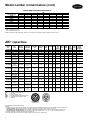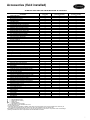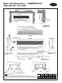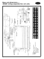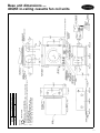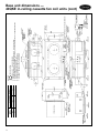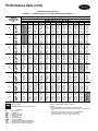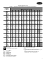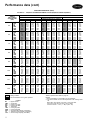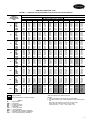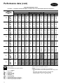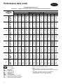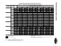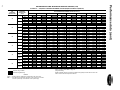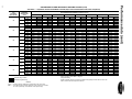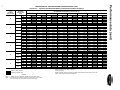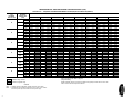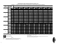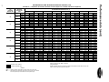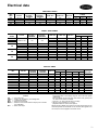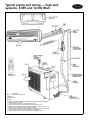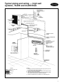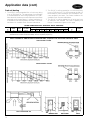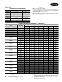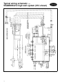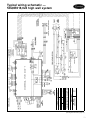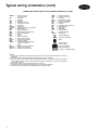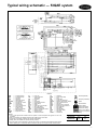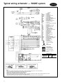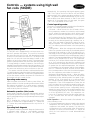
1
53QAE/53QKE/53QNE
Duct-Free Heat Pump
Split Systems
Product
Data
⁄ to 5 Nominal Tons
34
The Ideal Complement to Your
Ducted System When It Is Impractical or Prohibitively Expensive to
Use Ductwork
• cooling and heating duty
• choice of 3 compact, attractive fan
coil types for ultimate flexibility in
any room decor
• wide range of accessories available to meet a variety of installation requirements
• year-round comfort control
HEAT PUM
P
38QR-C
Features/Benefits
An inexpensive and creative
solution to design problems
40QNE
40QAE
40QKE
Copyright 1997 Carrier Corporation
Carrier’s heat pump duct-free split
systems are a matched combination of
an outdoor heat pump unit and a
decorative indoor fan coil unit connected only by refrigerant tubing and
wires. One of the 3 fan coil choices
will fit any application you might
encounter.
The fan coils can be mounted on
the wall, at the ceiling, or in the ceiling. This selection of fan coils permits
inexpensive and creative solutions to
design problems such as:
• add-ons to current space (an office
or family room addition)
• special space requirements (a computer room)
• when changes in the cooling or
heating load cannot be handled
by the existing system (when adding
heat-generating equipment to a
currently conditioned space)
• historical renovations or any application where preserving the looks
of the original structure is essential
These compact indoor fan coil units
take up very little space in the room
and will not obstruct windows. The
fan coils are attractively styled to
blend with most room decors.
Form 53-4PD
Advanced system components incorporate innovative technology to
provide reliable cooling and heating
performance at high efficiencies and
low sound levels.
Carrier’s duct-free split systems
offer the solution of choice. The compressor is outdoors, linked by refrigerant lines to an indoor fan coil located
directly in the room it will cool or
heat. These systems have minimal impact on the existing structure, and
the design and interior of the conditioned space is not compromised
by bulky ductwork. Because of these
features, Carrier’s duct-free split
systems can be installed in places
where conventional ducted cooling
and heating units simply cannot go.
Low sound levels
When noise is a concern, the ductfree split systems are the answer
because you do not have to worry
about duct design. There are no compressors indoors, either in the conditioned space or directly over it, and
there is none of the noise usually
generated by air being forced through
ductwork. These indoor units are
whisper quiet. The outdoor units
operate at sound levels as low as
65 Decibels, and are the perfect
answer to sound level ordinances.
When sound ordinances and proximity to neighbors demand ultraquiet operation, the 38QR-C and
38BK are the right choices: The advanced, horizontal airflow design
distributes air more evenly over the
coil. On the 38QR-C unit and
38BK018 and 024 units, the coil
acts as an extra sound-muffling device
before the air is discharged at a very
low velocity.
High efficiency
With SEERs (seasonal energy efficiency ratios) up to 11.5 and HSPFs
(heating seasonal performance factors)
up to 7.6, the Carrier duct-free split
systems save energy and may qualify
for utility company rebates in some
areas.
Secure operation
If security is an issue, outdoor and
indoor units are connected only by
refrigerant piping and wiring to prevent intruders from crawling through
ductwork. In addition, since 38QR-C
units can be installed 6 in. away
from outside walls, coils are protected
from vandals and severe weather.
Fast installation
Carrier’s compact duct-free split systems take just a few hours to install, since only wire and piping need
2
to be run. The fast and easy
installation permits minimal disruption
to customers in the home or workplace. This is an added advantage of
Carrier’s duct-free split systems, especially in retrofit situations.
Features like mounting brackets and
templates make the unit very easy to
install. In fact, the ceiling-suspended
units are even furnished with indoor-tooutdoor connecting cables.
Simple servicing and
maintenance
Removing a single panel on outdoor
units provides immediate access to the
isolated compressor and control
compartment, allowing a service technician access to check unit operation without a loss of condenser
airflow. In addition, on 38QR-C units,
the blow-thru design of the outdoor
section means that dirt accumulates
on the inside surface of the coil. Coils
can be cleaned quickly from the outside using a pressure hose and detergent without removing grilles or
using fin combs.
On indoor units, service and maintenance expense is reduced due to
easy-to-change cleanable filters on all
units. In addition, the high wall systems have extensive self-diagnostics to
assist in troubleshooting. All units
have easy-access coils and cleanable
condensate pans to assist in meeting indoor air quality standards.
Both refrigerant service valves are
brass, back-seating type with sweat
(38QR-C and 38BK018,024) or flare
(38BK009,012) connections. The
valves are externally located so refrigerant tube connections can be made
quickly and easily. Each valve has
a service port for ease of checking
operating refrigerant pressures
(38QR-C and 38BK018,024 units).
Internal service ports (38QR-C and
38BK018,024) are also provided
to make servicing even easier, and the
heating refrigerant metering device
is conveniently located in the liquid-line
service valve (38QR-C and
38BK018,024 only).
Built-in reliability
Carrier duct-free split system indoor
and outdoor units are designed to provide years of trouble-free operation.
The high wall indoor units include
freeze-up protection, high temperature
protection, and self diagnostics. Other
indoor units are protected by outdoor unit controls and have limited
diagnostics available through standard
or accessory 24v thermostats.
Carrier’s 38QR-C and 38BK018,
024 outdoor units are the only
dedicated commercial units with all
safety features standard to ensure high
performance and lasting reliability
under the most demanding situations.
For example, an accumulator safeguards the compressor against loss of
lubrication, while start capacitors
and relays (non-scroll units) assure
dependable start-ups, especially during
low voltage conditions down to
187 v. High- and low-pressure safety
switches, crankcase heater (non-scroll
units), bi-flow liquid line filter drier,
and lockout protection are standard
on most sizes and Time Guardt compressor protection can be included.
NOTE: Time delay compressor protection is provided by the microprocessor or 24v thermostat when outdoor
unit is matched with 40QAE or
40QKE fan coil units.
The totally-enclosed outdoor-fan
motor means greater reliability under
rain conditions, ensuring dependable performance for many years.
Table of contents
Page
Features/Benefits . . . . . . . . . . . . . . . . . . . . . . . . . . . . . . . . . . . . . . . . . . . . . . . . . 1-4
Model Number Nomenclature . . . . . . . . . . . . . . . . . . . . . . . . . . . . . . . . . . . . . . . 5,6
ARI Capacities . . . . . . . . . . . . . . . . . . . . . . . . . . . . . . . . . . . . . . . . . . . . . . . . . . . . . 6
Accessories . . . . . . . . . . . . . . . . . . . . . . . . . . . . . . . . . . . . . . . . . . . . . . . . . . . . . . 7-10
Physical Data . . . . . . . . . . . . . . . . . . . . . . . . . . . . . . . . . . . . . . . . . . . . . . . . . . . 11-17
Base Unit Dimensions . . . . . . . . . . . . . . . . . . . . . . . . . . . . . . . . . . . . . . . . . . . . 18-24
Selection Procedure . . . . . . . . . . . . . . . . . . . . . . . . . . . . . . . . . . . . . . . . . . . . . . . 25
Performance Data . . . . . . . . . . . . . . . . . . . . . . . . . . . . . . . . . . . . . . . . . . . . . . . 26-58
Electrical Data . . . . . . . . . . . . . . . . . . . . . . . . . . . . . . . . . . . . . . . . . . . . . . . . . . . . 59
Typical Piping and Wiring . . . . . . . . . . . . . . . . . . . . . . . . . . . . . . . . . . . . . . . . 60-63
Application Data . . . . . . . . . . . . . . . . . . . . . . . . . . . . . . . . . . . . . . . . . . . . . . . . 64-71
Typical Wiring Schematics . . . . . . . . . . . . . . . . . . . . . . . . . . . . . . . . . . . . . . . . 72-76
Controls . . . . . . . . . . . . . . . . . . . . . . . . . . . . . . . . . . . . . . . . . . . . . . . . . . . . . . . . 77-81
Guide Specifications . . . . . . . . . . . . . . . . . . . . . . . . . . . . . . . . . . . . . . . . . . . . . 82-87
Features/Benefits (cont)
Individual room comfort
Maximum comfort is provided because
each space can have individual set
points and may be controlled based
on actual usage. The air sweep feature
provided on high wall and ceilingsuspended systems permits optimal
room air mixing to eliminate hot and
cold spots and enhance occupant
comfort.
Heat pumps with booster heat
mode (cassette and ceiling suspended
units) provide even greater comfort
in heat pump operation. With the
high wall unit, warm-start features
mean occupants are never subjected
to cold drafts on start-up or defrost.
Economical operation
Carrier’s duct-free split system design
allows individual room cooling and
heating only where required. There is
no need to run large supply-air fans
or chilled water pumps to handle
a few spaces with unique load patterns. In addition, because air is moved
only in the space required, no energy
is wasted moving air through ducts.
Features like the permanent
split-capacitor type motors provide
more economical operation, and the
rifled copper tube with louvered aluminum plate fin coil provides maximum
heat transfer.
When demand defrost is used with
high wall units, only the minimum
amount of energy is used to defrost
the coil. In addition, the blow-thru
design of the 38QR-C units results in
even lower energy usage in defrost
mode.
Lightweight, compact size
The small footprint of these units provides additional benefits. Carrier’s
exclusive aeroacoustics make these
units the most compact in the industry. Because they require minimal
service and airflow clearances, outdoor units can be located virtually anywhere — on the ground, roof,
balcony, under a deck, or even
mounted to an outside wall.
The outdoor unit can be mounted
on any type or weight roof, and the
indoor units take up little valuable,
rentable space. Because they are ductfree, not having to run large ductwork leaves additional space to be
rented or utilized, making the building
even more profitable.
In addition, the small size makes
these units easily moveable. When
floor plans change, the units can be
quickly reinstalled.
Easy-to-use controls
The microprocessor-based control in
the high-wall unit is easy to use,
permitting quick changes for maximum comfort. The microprocessor offers the ultimate in comfort and
efficiency. All units automatically
restart and retain their memories after
a power failure, eliminating unnecessary service calls and service disruption. High-wall units are equipped
1
2
3
4
5
—
—
—
—
—
6
7
8
9
10
11
12
13
—
—
—
—
—
—
—
—
14 —
with a wireless remote controller.
Under-ceiling and in-ceiling cassette
units feature standard 24v controls
with new solid-state multifeatured electronic thermostats. All units can be
easily integrated into most building
control systems, and offer autochangeover from heating to cooling
mode and back.
Wide range of accessories
Customizing the Carrier duct-free split
systems to your application is easily
accomplished through the many accessories available. Low-ambient temperature capability (permitting cooling
operation down to –20 F outdoor
ambient) is easily added on all units.
Accessories for the high-wall and
ceiling-suspended fan coils include an
internal condensate pump to provide installation flexibility. Condensate
pumps are standard on in-ceiling
cassettes. Ventilation-air capability is
available as an accessory on ceiling suspended units and in-ceiling cassettes. In addition, limited ducting
capability is available to connect inceiling cassettes (for example, to duct
to an adjacent room).
Agency listings
All systems are listed with ARI (Air
Conditioning & Refrigeration Institute), UL (Underwriters’ Laboratories),
CSA (Canadian Standards Association), and CEC (California Energy
Commission).
LEGEND
Start Capacitor and Relay
Lockout
3-Pole Contactor
High-Voltage Terminal Block
Time Temperature Solid-State
Defrost Board (Not used with 40QNE
fan coil units)
Low-Voltage Terminal Block
Accumulator
Liquid Line Low-Pressure Switch
High-Pressure Switch
Acoustic Lining
Crankcase Heater
Isolated Compressor/Control Area
Discharge and Suction Pressure
Gage Ports
Reversing Valve
UNIT SHOWN IS
38QR-C HEAT PUMP
3
Features/Benefits (cont)
HIGH WALL FAN COILS —
40QNE (3⁄4 - 2 Tons)
High wall systems are the most cost-effective duct-free split systems. They can be
used for simple add-ons and retrofits where wall space is available.
CEILING-SUSPENDED FAN COILS —
40QAE (11⁄2 - 5 Tons)
Use ceiling-suspended systems for office and retrofit applications where there
is little or no wall space.
IN-CEILING CASSETTE FAN COILS —
40QKE (2 - 4 Tons)
Cassette systems are ideal for retrofit and modernization projects with
standard 2-ft x 4-ft hung ceilings.
4
Model number nomenclature
53 SERIES DUCT-FREE HEAT PUMP SPLIT SYSTEMS
*53QNE009 only.
NOTE: System voltage is the voltage of the outdoor unit.
38 SERIES HEAT PUMP OUTDOOR UNITS
*38BK009 only.
40 SERIES HEAT PUMP FAN COILS
*40QNE009 only.
5
Model number nomenclature (cont)
SYSTEM AND COMPONENT AVAILABILITY
SIZE
SYSTEM
OR COMPONENT
009
X
53QNE
53QAE
53QKE
38BK
38QR-C
40QNE
40QAE
40QKE
012
X
X
X
X
X
018
X
X*
X*
X
X
X
024
X
X
X†
X
X
X
X
X
030
036
048
060
X†
X†
X
X**
X
X
X
X
X
X
X
X
X
X
X
*Uses an 024 size indoor unit.
†Uses an 036 size indoor unit.
**Uses an 048 size indoor unit.
NOTE: See Systems Index Index table, page 26 for a complete list of systems including components used for each.
ARI* capacities
SYSTEM
MODEL
NO.
FAN
COIL
TYPE
53QNE009
53QNE012
53QNE018
53QNE024
High Wall
High Wall
High Wall
High Wall
Ceiling
Suspended
Ceiling
Suspended
Ceiling
Suspended
53QAE018
53QAE024
53QAE030
INDOOR
SECTION
OUTDOOR
SECTION
STANDARD
CFM
NET
COOLING
(BTUH)
TOTAL
kW
SEER
EER
40QNE009
40QNE012
40QNE018
40QNE024
38BK009
38BK012
38BK018
38BK024
252
302
455
525
8,700
12,500
17,300
23,200
0.95
1.28
1.71
2.23
10.0
10.5
11.5
11.0
9.2
9.8
10.1
10.4
HIGH
HEAT
CAP
(BTUH)
9,000
12,500
16,900
21,400
40QAE024
38QR-C018
500
19,000
1.90
11.00
10.0
40QAE024
38QR-C024
525
24,000
2.40
11.00
40QAE036
38QR-C030
870
30,000
2.94
870
34,600
870
53QAE036
Ceiling
Suspended
40QAE036
53QAE036
Ceiling
Suspended
40QAE036
53QAE048
53QAE060
53QKE018
53QKE024
53QKE030
Ceiling
Suspended
Ceiling
Suspended
In-Ceiling
Cassette
In-Ceiling
Cassette
In-Ceiling
Cassette
3.20
3.00
2.85
2.90
6.80
6.80
6.80
6.80
HEAT
LOW
CAP
(BTUH)
5,120
7,190
10,100
12,700
2.2
2.3
2.05
2.20
OUTDOOR
SOUND
RATING
(Decibels)
65
65
68
68
17,000
3.20
7.20
9,800
2.1
70
10.0
22,600
3.00
7.30
12,500
2.0
68
11.00
10.2
28,000
3.30
7.40
15,600
2.2
68
3.39
11.50
10.2
33,000
3.30
7.15
19,000
2.2
68
36,000
3.67
11.00
9.8
34,400
3.00
6.80
19,800
2.0
74
1100
48,000
5.00
10.20
9.6
45,500
3.20
7.30
28,200
2.2
76
40QAE060
38QR-C060
1600
58,000
5.85
11.00
9.9
57,500
3.15
7.40
32,000
2.2
72
40QKE024
30QR-C018
525
18,000
2.00
10.00
9.0
17,600
3.04
6.80
11,000
2.0
68
40QKE036
38QR-C024
980
25,000
2.44
10.70
10.2
23,800
3.34
7.60
13,400
2.3
68
40QKE036
38QR-C030
980
29,000
2.61
11.50
11.1
27,000
3.27
7.60
15,900
2.3
68
1100
33,000
3.47
10.50
9.5
33,000
3.30
6.80
20,000
2.2
70
1100
34,400
3.65
10.00
9.2
34,000
3.00
6.80
21,000
2.0
74
40QKE048
53QKE036
In-Ceiling
Cassette
40QKE048
38QR-C036
Single-Phase
Unit
38QR-C036
3-Phase
Unit
LEGEND
Coefficient of Performance
Dry-Bulb
Energy Efficiency Ratio
Heating Seasonal Performance Factor
Seasonal Energy Efficiency Ratio
Wet-Bulb
ARI 210/240
ARI 270
(When used with
matching unit.)
*Air Conditioning & Refrigeration Institute.
NOTES:
1. Ratings are net values reflecting the effects of circulating fan heat. Supplemental electric heat is not included. Ratings are based on:
Cooling Standard: 80 F db, 67 F wb indoor entering air temperature and 95 F db air entering outdoor unit.
High-Temperature Heating Standard: 70 F db indoor entering air temperature and 47 F db, 43 F wb air entering outdoor unit.
Low-Temperature Heating Standard: 70 F db indoor entering air temperature and 17 F db, 15 F wb air entering outdoor unit.
2. Ratings are based on 15 ft of interconnecting refrigerant line.
3. The total kW is for the total system, including compressor and indoor and outdoor fans.
6
HEAT
LOW
COP
38QR-C048
In-Ceiling
Cassette
—
—
—
—
—
—
HIGH
HEAT
HSPF
40QAE048
53QKE036
COP
db
EER
HSPF
SEER
wb
38QR-C036
Single-Phase
Unit
38QR-C036
3-Phase
Unit
HIGH
HEAT
COP
Accessories (field installed)
STANDARD FEATURES AND FIELD-INSTALLED ACCESSORIES
STANDARD FEATURE/FIELD-INSTALLED
53QNE
53QAE
ACCESSORY
(High Wall)
(Ceiling Suspended)
Condensate Pump
A
A
Mounting Brackets
S
S
Microprocessor Controls
S
—
24-V Electro-Mechanical Controls
—
S
Cleanable Filters
S
S
Charcoal Filter Kit
A
—
Programmable Electronic Thermostat
—
A
3-Speed Indoor-Fan Motor
S
S
Automatic Indoor-Fan Speed Control
S
S
Diagnostics
S
S*
Galvanized Steel Casing (Indoor Unit)
—
—
Wired and Wireless Remote Controllers
S (WR)
S (W)
Fully Insulated Indoor Unit Cabinet
S
S
Automatic Air Sweep
S
S
User-Controlled Air Distribution
—
—
Power Ventilation Kit
—
A
Fresh Air Intake Kit
—
A
Indoor Guard (Discharge Grille)
—
A
Auto Restart Function
S
S
24-Hour Automatic Start/Stop Timer
S
A
50-ft 24v Control Power Cable†
—
S
35-ft 24v Control Power Cable
S (018,024)
—
35-ft Power and Control Cable
S (009,012)
—
Refrigerant Line Turn Elbow†
—
S
Thermistor Cable Assembly
S
—
High- and Low-Voltage Terminal Blocks (Indoor)
S
S
AccuRaterT Refrigerant Metering Device
S
S
Electric Heat
—
S
Demand Defrost
S
—
Time/Temperature Defrost
—
S
Warm Start (in heating)
S
—
Evaporator Coil Freeze Protection
S
—
Outdoor High- and Low-Voltage Terminal Block
S
S
Accumulator
S
S
Crankcase Heater (Reciprocating Compressors)
S
S
Crankcase Heater (Scroll Compressor Units)**
A
A
High-Pressure Switch†
S
S
Loss of Charge Switch†
S
S
5-Year Compressor Warranty
S
S
Compressor Start Assistance (non-scroll units)
S
S
Cycle-LOC™ Device†
S
S
Suction and Discharge Service Taps††
S
S
Totally Enclosed Outdoor Fan Motor
S
S
Acoustically-Lined Compressor Compartment
S
S
Low Ambient Temperature Controls (down to −20 F)
A
A
Heating Operation to −20 F
S
S
Auto Changeover from Cooling to Heating
S
S
Liquid Solenoid Valve†
A
A
FIELD FABRICATED AND FIELD INSTALLED ACCESSORIES|
Stacking Rails†
A
A
Condensing Unit Wall Mount Kit†
A
A
Snow Stand†
A
A
Ice Stand†
A
A
Wind Baffles†
A
A
53QKE
(In-Ceiling Cassette)
S
S
—
S
S
—
A
S
S
S*
S
S (W)
S
—
S
A
A
—
S
A
—
—
—
—
—
S
S
S
—
S
—
—
S
S
S
A
S
S
S
S
S
S
S
S
A
S
S
A
A
A
A
A
A
LEGEND
A
— Field-Installed Accessory
S
— Standard from the Factory
W
— Wired (24v)
WR — Wireless Remote
—
— Not Available on this System
*Limited diagnostics through standard 24v control.
†For size 018 and larger.
**Crankcase heaters are standard on 38QR-C units without scroll compressors, and are recommended as an accessory for
scroll compressor applications with line lengths over 100 ft and applications using low-ambient kits.
††The 38QR-C units are equipped with 4 taps; one for each service valve, and one each on compressor suction and discharge.
\Drawings available from Carrier representative for field fabricated accessories.
7
Accessories (field installed) (cont)
See Standard Features and Field-Installed Accessories table on page 7 for information on
system features and accessories.
CONDENSATE PUMPS
Condensate pumps provide condensate lift capability of 20 in. on
ceiling-suspended (40QAE) fan coils. On high wall fan coils, condensate pump has a lift capability of 1 to 10 ft (009 unit) or 3 to 25 ft
(012-024 units). The pump mounts inside the unit with quick plug-in
connections, and is recommended when adequate drain line pitch
cannot be provided.
NOTE: This pump is standard on the in-ceiling cassette (40QKE) fan
coils, where it provides a lift capability of 20 in. above the condensate pan.
FRESH AIR INTAKE KIT
Fresh air intake kit provides for a variable amount of outdoorair capability for the ceiling-suspended (40QAE) and cassette (40QKE) fan coils. Up to 30% outdoor-air can be supplied to 40QAE units and up to 10% can be supplied to 40QKE
units. The filter is mounted at the fan coil unit and provides
filtering of outdoor air before it enters the unit. (Ceilingsuspended system application is shown.)
8
CHARCOAL FILTER KIT
COLLECTOR
The charcoal (carbon) filter kit is available for duct-free high wall fan
coil units. This accessory improves indoor air quality by removing
volatile organic compounds (VOCs), odors, and micro-particles from
the air. The filter kit can be installed either before or after the unit
has been mounted to the wall. Filters must be changed approximately every 3 months.
ACTIVE
CARBON
FILTER
(FILTER FOR 009 SIZE SHOWN)
POWER VENTILATION KIT
Power ventilation kit provides for up to 10% outdoor air intake capability for the in-ceiling cassette (40QKE) units and up to 30% capability on ceiling-suspended (40QAE) units. The filter is mounted at
the fan coil unit and filters the outdoor air. A booster fan with speed
control is provided to allow for long duct runs and to balance airflow
to the unit for consistent unit operation.
9
Accessories (field installed) (cont)
Outdoor units
Low-ambient kit includes a solid-state head pressure controller designed to control condenser fan cycling, and is activated by a pressure sensor. It is specifically designed to
control fan-motor cycles in response to saturated condensing pressure. This device maintains a constant saturated condensing temperature of 100 F ± 10 F at outdoor-air temperatures between 55 F and –20 F, and can be used on all
outdoor units without changing the outdoor-fan motor.
Liquid solenoid valve is an electrically operated shutoff
valve that is installed at the outdoor unit to stop and start
refrigerant flow in response to compressor operation. The
valve maintains a column of refrigerant in the liquid line between compressor operating cycles and is required for certain long-line applications and to improve system performance. The valve should be used with all long-line applications
(over 100 ft).
Crankcase heater is available for units with scroll compressors. Heater clamps onto compressor oil sump. Recommended for low-ambient applications.
Field fabricated accessories
Field fabricated accessories including the stacking kit, snow
or ice stand, wind baffles, and wall mount brackets must be
constructed in the field using field-supplied materials. For
drawings, contact your Carrier representative.
Stacking rails allow stacking of equally-sized units or permit smaller units to be stacked on top of larger units. These
field fabricated rails can be used for stacking all size 018
and larger units.
10
Snow or ice stands raise the outdoor unit above snow
and ice surfaces to permit normal air circulation, condensate drainage, and maintenance clearances in areas where
prolonged subfreezing temperatures or heavy snowfalls occur. The snow rack/ice stand must be field fabricated and
can be used on all size 018 and larger outdoor units.
Wind baffle is a field fabricated sheet metal wrapper used
to provide improved unit operation during high winds, and
is recommended for size 018 or larger outdoor units whenever the low-ambient accessory is used.
Wall mount brackets are mounted to the outside of the
structure to raise unit from ground level, or to mount the
unit on a wall adjacent to a sloping roof. Wall mounts are
also useful in areas of heavy snowfall or where space is at a
premium. Wall mounts must be field fabricated and can be
used with any size 018 or larger outdoor unit.
Fan coils
Indoor guard is a decorative wire guard for the ceilingsuspended (40QAE) fan coils. The guard mounts over the
fan coil discharge to prevent objects from entering the unit
and air sweep.
Electronic programable thermostats are available for
in-ceiling cassette (40QKE) and ceiling-suspended (40QAE)
fan coils. These commercial-grade thermostats provide 7-day,
4 event-per-day scheduling. The integral subbase provides
3-speed fan switchover capability, air sweep, auto changeover, and non-volatile memory (no battery required).
Physical data — 38BK009,012 outdoor
heat pump units*
UNIT 38BK
NOMINAL CAPACITY (Tons)
OPERATING WEIGHT (lb)
REFRIGERANT TYPE
Control (Cooling)
Control (Heating)
Factory Charge (lb)
COMPRESSOR TYPE
Model
Oil (Recharge) (oz)
CRANKCASE HEATER (Watts)
OUTDOOR FAN
Rpm
Diameter (in.)...No. of Blades
Motor Watts
Nominal Air Cfm
OUTDOOR COIL
Face Area (sq ft)...No. of Rows
Fins/in.
CONTROLS
Fusible Plug
Accumulator
Defrost Method
Control Voltage
REFRIGERANT LINES
Connection Type
Liquid Line OD (in.)
Vapor Line OD (in.)
Maximum Length (ft)
Maximum Lift (Fan Coil Above) (ft)
Maximum Lift (Fan Coil Below) (ft)
EXTERNAL FINISH
009
3⁄4
60.7
012
1
66.5
R-22
AccuRaterT Piston at Outdoor Unit
AccuRater Piston at Outdoor Unit
1.5
2.0
Carrier Hermetic Rotary
EBA095111H
10.1
EBB130111H
10.1
40
Propeller, Direct Drive
850
121⁄4...4
87
756
850
121⁄4...4
87
756
Copper Tube, Aluminum Fin
3.5...1
18
3.5...2
17
210 F
Yes
Demand
115 v
210 F
Yes
Demand
230 v
Male Flare
1/4
1/2
35
16
30
1/4
1/2
35
16
30
White
*These units may only be used with 40QNE fan coil units.
11
Physical data — 38BK018,024 and 38QR-C
outdoor heat pump units
UNIT
NOMINAL CAPACITY (Tons)
OPERATING WEIGHT (lb)
REFRIGERANT TYPE
Control (Cooling)
Control (Heating)
Factory Charge (lb)†
COMPRESSOR TYPE
Model
Oil (Recharge) (oz)
CRANKCASE HEATER (Watts)
OUTDOOR FAN
Rpm
Diameter (in.)...No. of Blades
Pitch (Degrees)
Motor Hp
Nominal Air Cfm
OUTDOOR COIL
Face Area (sq ft)...No. of Coils
Fins/in.
CONTROLS
High-Pressure (psig)
Cutout
Cut-in
Liquid Line Low-Pressure (psig)
Cutout
Cut-in
Fusible Plug
Defrost Method**
Accumulator
Control Voltage††
REFRIGERANT LINES
Connection Type
Liquid Line OD (in.)
Vapor Line OD (in.)
Maximum Length (ft)
Maximum Lift (Fan Coil Above) (ft)
Maximum Lift (Fan Coil Below) (ft)
EXTERNAL FINISH
38BK-018*
38QR-C018
11⁄2
154
38BK024*
38QR-C024
2
167
38QR-C030
2 1 ⁄2
180
R-22
AccuRaterT Piston at Fan Coil Unit
AccuRater Piston at Outdoor Unit
1.5
Tecumseh Reciprocating
Copeland Scroll
AW5519G
AW5524G
ZR28K1
ZR34K1
30
30
24
30
19
19
None
None
Propeller, Direct Drive
850
850
850
850
18...3
18...3
18...3
18...3
25
27
27
31
1⁄8
1 ⁄8
1⁄8
1 ⁄8
1720
1720
1720
1720
Copper Tube, Aluminum Fin
6.1...1.5
6.1...2
6.1...3
6.1...3
15
15
15
15
320 ± 20
426 ± 7
7± 3
22 ± 5
210 F
Time and Temperature Defrost
Yes
24 v
⁄
5⁄8
200
65
150
38
Sweat—Suction; Flare—Liquid
3 ⁄8
3⁄8
5 ⁄8
3⁄4
200
200
65
65
150
150
Alpine Mist (Beige)
*These units may only be used with 40QNE fan coil units.
†See Piston Guide tables on page 66 for proper charge. These units are shipped with a holding charge only.
**Demand defrost when used with 40QNE fan coil units.
††A 24-v transformer is provided in the fan coil unit; 38BK018 and 024 units have their own transformers.
\ Valve connection size is 3⁄4 inch. Recommended line size is 7⁄8 inch.
12
38QR-C036
(Single-Phase)
3
184
⁄
⁄ \
200
65
150
38
78
UNIT
NOMINAL CAPACITY (Tons)
OPERATING WEIGHT (lb)
REFRIGERANT TYPE
Control (Cooling)
Control (Heating)
Factory Charge (lb)*
COMPRESSOR TYPE
Model
Oil (Recharge) (oz)
CRANKCASE HEATER (Watts)
OUTDOOR FAN
Rpm
Diameter (in.)...No. of Blades
Pitch (Degrees)
Motor Hp
Nominal Air Cfm
OUTDOOR COIL
Face Area (sq ft)...No. of Coils
Fins/in.
CONTROLS
High-Pressure (psig)
Cutout
Cut-in
Liquid Line Low-Pressure (psig)
Cutout
Cut-in
Fusible Plug
Defrost Method
Accumulator
Control Voltage†
REFRIGERANT LINES
Connection Type
Liquid Line OD (in.)
Vapor Line OD (in.)
Maximum Length (ft)
Maximum Lift Fan Coil (Above) (ft)
Maximum Lift Fan Coil (Below) (ft)
EXTERNAL FINISH
38QR-C036 (3-Phase)
3
249
Copeland Reciprocating
CRH3-0275
51
40
850
24...3
24
1⁄4
3900
12.3...2
15
38QR-C048
4
252
R-22
AccuRater® Piston at Fan Coil Unit
AccuRater Piston at Outdoor Unit
2.0
Tecumseh Reciprocating
AV5549G
50
27
Propeller, Direct Drive
850
24...3
24
1 ⁄4
3900
Copper Tube, Aluminum Fin
12.3...2
15
38QR-C060
5
272
Copeland Reciprocating
CRP5-0450
66
40
850
24...3
24
1 ⁄4
3900
12.3...3
15
320 ± 20
426 ± 7
7± 3
22 ± 5
210 F
Time and Temperature
Yes
24 v
⁄
⁄
200
65
150
38
34
Sweat—Suction; Flare—Liquid
3 ⁄8
7 ⁄8
200
65
150
Alpine Mist (Beige)
3 ⁄8
11⁄8**
200
65
150
*See Piston Guide tables on page 66 for proper charge. These units are shipped with a holding charge only.
†A 24-v transformer is provided in the fan coil unit.
**Valve connection is 7⁄8 inch. Recommended line size is 11⁄8 inch.
13
Physical data — high wall units
UNIT 40QNE
NOMINAL CAPACITY (Tons)
NOMINAL SIZE (Btuh)
OPERATING WEIGHT (lb)
MOISTURE REMOVAL RATE (Pints/hr)
FINISH
REFRIGERANT
Control (Cooling)
Control (Heating)
Factory Charge (lb)†
INDOOR FAN
Rpm/Cfm High
Rpm/Cfm Medium
Rpm/Cfm Low
Motor Watts
Blowers Quantity...Size (in.)
INDOOR COIL
Face Area
No. of Rows
Fins/in.
Circuits
FILTERS
Quantity...Size (in.)
AIRSWEEP
Horizontal
Vertical
CONTROLS
Remote Controller Options
Diagnostics
Defrost Method
Timer Mode
Warm Start Feature
Test Mode
Freeze Protection
Dehumidification Mode
Fan Mode
Auto Changeover
Auto Restart
Control Voltage
REFRIGERANT LINES
Connection Type
Liquid Line OD (in.)
Vapor Line OD (in.)
Maximum Length (ft)
Maximum Lift (Fan Coil Above) (ft)
Maximum Lift (Fan Coil Below) (ft)
CONDENSATE DRAIN SIZE (in.)
009*
3⁄4
9000
18.7
2.4
012*
1
12,000
24.2
3.4
White
R-22
AccuRater® Piston at Outdoor Unit
AccuRater Piston at Outdoor Unit
1.5
2.0
Direct Drive Centrifugal
1200/240
1040/260
1100/210
940/240
1000/180
850/210
34
35
1...3.54 × 27.75
1...3.94 × 27.75
Copper Tube, Aluminum Fin
1.45
1.6
2
2
18
17
2
3
Cleanable
2...9 x 12
2...91⁄2 x 133⁄4
Manual
Automatic
Integrated Microprocessor
Wireless
Yes
Demand Defrost
Yes
Yes
Yes
Yes
Yes
High/Medium/Low/Auto
Yes
Yes
115 v
230 v
Male Flare
⁄
⁄
35
16
30
⁄
1 ⁄2
35
16
30
14
14
12
*These units may only be matched with 38BK outdoor units.
†Full factory charge is shipped in the outdoor unit. The charge is determined based on 25 ft of line.
14
⁄ OD, 7⁄16 ID
58
UNIT 40QNE
NOMINAL CAPACITY (Tons)
NOMINAL SIZE (Btuh)
OPERATING WEIGHT (lb)
MOISTURE REMOVAL RATE (Pints/Hr)
FINISH
REFRIGERANT
Control (Cooling)
Control (Heating)
Charge Required (lb)
INDOOR FAN
Rpm/Cfm High
Rpm/Cfm Medium
Rpm/Cfm Low
Motor Watts
Blowers Quantity...Size (in.)
INDOOR COIL
Face Area (sq ft)
No. of Rows
Fins/in.
Circuits
FILTERS
Quantity...Size (in.)
AIRSWEEP
Horizontal
Vertical
CONTROLS
Remote Controller Options
Diagnostics
Defrost Method
Timer Mode
Warm Start Feature
Test Mode
Freeze Protection
Dehumidification
Auto. Changeover
Fan Mode
Auto Restart
Control Voltage
REFRIGERANT LINES
Connection Type
Liquid Line OD (in.)
Vapor Line OD (in.)
Maximum Length (ft)
Maximum Lift (Fan Coil Above) (ft)
Maximum Lift (Fan Coil Below) (ft)
CONDENSATE DRAIN CONNECTION (in.)
018
11⁄2
18,000
38.5
5.6
024
2
24,000
42.9
6.3
White
R-22
AccuRaterT Piston in Fan Coil
AccuRater Piston in Outdoor Unit
4.95
5.1
Direct Drive Centrifugal
1120/530
1470/570
1050/490
1370/466
950/430
1270/447
42.3
49
2...3.94 x 17.8
2...3.94 x 17.8
Copper Tube, Aluminum Fin
2.56
2.56
2
3
15.9
18.1
2
3
Cleanable
2...111⁄2 x 173⁄4
Manual
Automatic
Integrated Microprocessor
Wireless
Yes
Demand Defrost
Yes
Yes
Yes
Yes
Yes
Yes
High/Medium/Low/Auto.
Yes
24 v (provided)
Flare
3⁄8
5⁄8
200
65
150
5⁄8 OD, 7⁄16 ID
*Outdoor unit is shipped with a holding charge. The amount of the charge is determined based on 25 ft of line. See Application Data section on
page 64 for information on longer line lengths and condensing unit combinations.
15
Physical data — ceiling-suspended units
UNIT
NOMINAL CAPACITY (Tons)
NOMINAL SIZE (Btuh)
OPERATING WEIGHT (lb)
MOISTURE REMOVAL RATE (Pints/hr)
FINISH
REFRIGERANT
Control (Cooling)
Control (Heating)
Charge Required (lb) Single Phase/3 Phase†
INDOOR FAN
Rpm/Cfm High
Rpm/Cfm Medium
Rpm/Cfm Low
High Speed Watts
Motor Quantity...Hp
Blowers Quantity...Size (in.)
INDOOR COIL
Face Area (sq ft)
No. of Rows
Fins/in.
Circuits
FILTERS
Quantity...Size (in.)
AIRSWEEP
Horizontal
Vertical
HEATER (kW)
CONTROLS
Remote Controller Options
Diagnostics
Defrost Method
Timer Mode
Freeze Protection
Test Mode
Auto. Changeover
Auto. Restart
Fan Mode
Booster Heat Mode
Control Voltage
REFRIGERANT LINES
Connection Type
Liquid Line OD (in.)
Vapor Line OD (in.)
Maximum Length (ft)
Maximum Lift (Fan Coil Above) (ft)
Maximum Lift (Fan Coil Below) (ft)
CONDENSATE DRAIN CONNECTION (in. MPT)
40QAE018*
11⁄2
18,000
110
5.8
4.3/—
900/480
862/400
770/320
92
1...1⁄16
2...6 x 8
2.2
4
14.9
4
4...12 x 83⁄4
40QAE024
40QAE036
40QAE048
2
3
4
24,000
36,000
48,000
110
119
151
7.1
9.5
13.4
GM Motorhome White with Black Trim
R-22
AccuRater® Piston in Fan Coil
AccuRater Piston in Fan Coil
6.3/—
7.5/8.7
10.0/—
Direct Drive Centrifugal
1050/550
1275/870
1435/1130
900/480
972/750
1388/975
862/400
830/630
1315/820
92
282
425
1
1
1... ⁄16
1... ⁄6
1...1⁄16, 1...1⁄6
2...6 x 8
2...6 x 8
3...6 x 8
Copper Tube, Aluminum Fin
2.2
2.6
3.0
4
4
4
14.9
14.9
14.9
4
4
8
Cleanable
4...105⁄8 x 83⁄4
4...12 x 83⁄4
5...105⁄8 x 83⁄4
2...12 x 83⁄4
40QAE060
5
60,000
181
15.1
11.9/—
1275/1600
972/1220
830/1040
564
2...1⁄6
4...6 x 8
4.0
4
14.9
8
6...12 x 83⁄4
—
Automatic
2.0
⁄
58
2.0
3.0
4.0
Solid-State Electromechanical
Hard-Wired
Yes (with Optional Thermostat)
Time/Temperature
Yes (with Optional Thermostat)
Through Outdoor Unit Low-Pressure Switch
Yes
Yes
Yes
High/Medium/Low/Auto
Yes
24 v (provided)
⁄
58
Flare
3⁄8
3 ⁄4
200
65
150
3⁄4††
⁄ **
78
5.0
⁄ **
78
*The 40QAE018 fan coil is a 40QAE024 fan coil, but uses a different motor speed fan tap plug than the 40QAE024. Refer to unit installation instructions for more details.
†Outdoor unit is shipped with a holding charge. The amount of charge listed is determined based on 25 ft of line. See Application Data section on
page 64 for information on longer line lengths and outdoor unit combinations.
**Valve connection size is 3⁄4 inch. Recommended line size is 7⁄8 inch.
††Flexible tubing (5⁄8 in.) is required when the accessory condensate pump is used.
16
Physical data — in-ceiling cassette units
UNIT
NOMINAL CAPACITY (Tons)
NOMINAL SIZE (Btuh)
OPERATING WEIGHT (lb)
MOISTURE REMOVAL RATE (Pints/hr)
FINISH
REFRIGERANT
Control (Cooling)
Control (Heating)
Charge Required (lb) Single Phase/3 Phase*
INDOOR FAN
Rpm/Cfm High
Rpm/Cfm Medium
Rpm/Cfm Low
High Speed Watts
Motor Quantity...Hp
Blowers Quantity...Size (in.)
INDOOR COIL
Face Area (sq ft)
No. of Rows
Fins/in.
Circuits
FILTERS
Quantity...Size (in.)
AIRSWEEP
HEATER kW
CONTROLS
Remote Controller
Auto. Restart
Diagnostics
Timer Mode
Auto. Changeover
Defrost Method
Freeze Protection
Fan Mode
Control Voltage
REFRIGERANT LINES
Connection Type
Liquid Line OD (in.)
Vapor Line OD (in.)
Maximum Length (ft)
Maximum Lift (Fan Coil Above) (ft)
Maximum Lift (Fan Coil Below) (ft)
CONDENSATE DRAIN CONNECTION
CONDENSATE DRAIN SIZE (in.)
40QKE024
2
24,000
66.1
7.0
40QKE036
40QKE048
3
4
30,000
36,000
105.8
118.0
8.6
9.6
White with Black Discharge Grille
R-22
AccuRater® Piston in Fan Coil
AccuRater Piston in Outdoor Unit
5.5/—
5.9/8.0
5.9/8.0
Direct Drive Centrifugal
1190/525
970/915
1180/1100
930/430
790/745
920/880
840/400
635/635
830/680
100
160
180
1
1
1... ⁄16
2... ⁄16
2...1⁄16
1...10 x 8
2...10 x 8
2...10 x 8
Copper Tube, Aluminum Fin
2.66
5.67
5.67
3
2
2
14.0
14.0
14.0
4
4
4
Cleanable
1...161⁄2 x 161⁄2
2...161⁄2 x 161⁄2
2...161⁄2 x 161⁄2
None
1.8
2.7
2.7
Solid-State Electromechanical
Hard Wired
Yes
Yes (with Optional Thermostat)
Yes (with Optional Thermostat)
Yes
Time/Temperature
Yes (Through Outdoor Unit Low-Pressure Switch)
High/Medium/Low/—Auto/Continuous
24 v (provided)
⁄
58
Flare
3⁄8
3 ⁄4
200
65
150
Hose
1.0
⁄
34
*The outdoor unit is shipped with a holding charge. The amount of charge listed is determined based on 25 ft of line. See Refrigerant Lines section on
page 65 for information on longer line lengths.
†When appropriate thermostat is used.
17
Base unit dimensions — 38BK009,012
outdoor units
NOTES:
1. Dimensions in [
2.
3.
] are in millimeters.
Direction of airflow.
Center of Gravity.
4. Minimum clearances: 4 in. on coil sides, 24 in.
on fan side, and 30 in. on service side.
18
UNIT
38BK
009
012
WEIGHT
Lb
60.7
66.5
Kg
27.5
30.2
38BK, 38QR-C018
38BK, 38QR-C024
38QR-C030
38QR-C036*
38QR-C036†
38QR-C048
38QR-C060
UNIT
ft-in.
2-11⁄8
2-11⁄8
2-11⁄8
2-11⁄8
3-13⁄16
3-13⁄16
3-13⁄16
A
mm
638.2
638.2
638.2
638.2
944.6
944.6
944.6
C
ft-in.
mm
ft-in.
3-015⁄16 938.2 1-29⁄16
3-015⁄16 938.2 1-29⁄16
3-015⁄16 938.2 1-29⁄16
3-015⁄16 938.2 1-29⁄16
3-89⁄16 1131.9 1-51⁄16
3-89⁄16 1131.9 1-51⁄16
3-89⁄16 1131.9 1-51⁄16
B
mm
369.9
369.9
369.9
369.9
433.4
433.4
433.4
ft-in.
1-4
1-4
1-4
1-4
1-67⁄16
1-67⁄16
1-67⁄16
D
mm
406.4
406.4
406.4
406.4
468.3
468.3
468.3
ft-in.
1-117⁄16
1-117⁄16
1-117⁄16
1-117⁄16
2-61⁄2
2-61⁄2
2-61⁄2
E
mm
595.3
595.3
595.3
595.3
774.7
774.7
774.7
ft-in.
1-53⁄16
1-53⁄16
1-53⁄16
1-53⁄16
1-75⁄8
1-75⁄8
1-75⁄8
ft-in.
1-51⁄2
1-51⁄2
1-51⁄2
1-51⁄2
2-55⁄8
2-55⁄8
2-55⁄8
UNIT SIZE
mm
436.6
436.6
436.6
436.6
498.5
498.5
498.5
mm
444.5
444.5
444.5
444.5
752.5
752.5
752.5
G
mm
511.2
511.2
511.2
511.2
817.6
817.6
817.6
ft-in.
1-1
1-1
1-1
1-1
1-17⁄8
1-111⁄16
1-21⁄2
J
mm
330.2
330.2
330.2
330.2
352.4
347.7
368.3
ft-in.
0-65⁄8
0-63⁄4
0-63⁄4
0-63⁄4
0-81⁄4
0-81⁄8
0-81⁄8
mm
168.3
171.5
171.5
171.5
209.5
206.4
206.4
K
ft-in.
0-111⁄4
0-115⁄8
0-115⁄8
0-115⁄8
1-4
1-37⁄8
1-37⁄8
L
mm
285.8
295.3
295.3
295.3
406.4
403.2
403.2
ft-in.
0-05⁄8
0-05⁄8
0-03⁄4
0-03⁄4
0-03⁄4
0-07⁄8
0-07⁄8
mm
15.88
15.88
19.05
19.05
19.05
22.22
22.22
M
Center of gravity.
4. Thermistors used with 40QNE fan coils only.
3.
OPERATING
WEIGHT
lb
Kg
154
69.8
167
75.7
180
81.6
184
83.5
249 112.9
252 114.3
272 123.4
MINIMUM MOUNTING PAD DIMENSIONS
Support Feet
Snow Stand
Ice Stand
ft-in.
mm
ft-in.
mm
ft-in.
mm
1-11 x 3-6 584.2 x 1066.8 2-2 x 3-6 660.4 x 1066.8 2-2 x 3-6 660.4 x 1066.8
2-0 x 4-2 609.6 x 1270
2-4 x 4-4 711.2 x 1270.0 2-2 x 4-2 660.4 x 1270.0
ft-in.
1-81⁄8
1-81⁄8
1-81⁄8
1-81⁄8
2-83⁄16
2-83⁄16
2-83⁄16
H
NOTES:
1. Required clearances, with coil facing wall; allow 6 in. minimum clearance
on coil side and coil end, and 3 ft minimum clearance on compressor end
and fan side. With fan facing wall; allow 8 in. minimum clearance on fan
side and coil end, and 3 ft minimum clearance on compressor end and coil
side. With multi unit application; arrange units so discharge of one does not
enter inlet of another.
2. Dimensions in [ ] are in millimeters.
018,024,030, 036*
036†,048,060
F
Base unit dimensions; 38BK018,024 and
38QR-C outdoor units
19
Base unit dimensions — 40QNE009,012
high wall fan coil units
NOTES:
1. Dimensions are in inches. Dimensions in [
2.
] are in millimeters.
Direction of airflow.
3. Refrigerant, drain, and power connections may be made rear, left side or right side.
4. Refrigerant is metered by AccuRaterT metering device in outdoor unit. Insulate both refrigerant lines.
5. Clearances of 31⁄29 on top of and to the left of the fan coil unit are absolute minimums. Clearances
of 109 are recommended.
20
UNIT
40QNE
009
012
WEIGHT
A
B
C
Lb
Kg
in.
mm
in.
mm in. mm
18.7 8.5 33.46 850 11.02 280 6.29 160
24.2 11.0 36.61 930 11.81 300 7.28 185
Base unit dimensions —
40QNE018,024 high wall fan coil units
NOTES:
1. Dimensions in (
2.
) are in millimeters.
Direction of airflow.
UNIT 40QNE
018
024
WEIGHT — LB (KG)
38.5 (17.5)
42.9 (19.5)
3. Refrigerant, drain, and power connections may be made rear, bottom,
left side, or right side.
4. Refrigerant is metered by AccuRaterT device at the fan coil unit.
5. The 49 top and left side clearances are absolute minimums. Clearances
of 109 are recommended.
21
22
Direction of airflow.
] are millimeters.
3. Facing unit discharge, unit clearances are as
follows:
0 in. on top and rear
3 in. on left side
12 in. on right side
36 in. on bottom
2.
NOTES:
1. Dimensions in [
WEIGHT
(lb)
110
119
151
181
UNIT
40QAE
018,024
036
048
060
A
ft-in.
4- 215⁄16
4-1013⁄16
5-119⁄16
7- 8
mm
1294
1493
1817
2336
ft-in.
3-10
4- 57⁄8
5- 65⁄8
7- 3
B
mm
1169
1368
1692
2211
ft-in.
4- 15⁄8
4- 91⁄2
5-101⁄4
7- 65⁄8
E
mm
1260
1459
1783
2302
F
ft-in.
—
—
1- 97⁄8
1-115⁄8
mm
—
—
555
601
G
ft-in.
mm
1- 95⁄8
549
2- 11⁄2
648
3- 31⁄16
992
4-119⁄16
1512
Base unit dimensions —
40QAE ceiling-suspended fan coil units
indicates airflow.
OPERATING WEIGHT
Lb
Kg
66.1
30
2. Dimensions in. [ ] are in millimeters.
3. Service clearance is 2 ft on control box side, 0 in. all other sides.
4. Air discharge slots are adjustable; one or 2 may be closed to direct air in
the desired direction.
5. Grille is shipped separately from unit.
6. Condensate pump has 20-in. lift capability.
7. AccuRaterT device must be field-installed.
1.
NOTES:
024
UNIT
40QKE
Base unit dimensions —
40QKE in-ceiling cassette fan coil units
23
24
036
048
UNIT
40QKE
OPERATING WEIGHT
Lb
Kg
105.8
48
118.0
53
2.
3.
4.
5.
6.
7.
1.
indicates airflow.
Dimensions in. [ ] are in millimeters.
Service clearance is 2 ft on control box side, 0 in. all other sides.
Air discharge slots are adjustable; one or 2 may be closed to direct air in the desired direction.
Grille is shipped separately from unit.
Condensate pump has 20-in. lift capability.
AccuRaterT device must be field-installed.
NOTES:
Base unit dimensions —
40QKE in-ceiling cassette fan coil units (cont)
Selection procedure (with example)
I Determine the type of fan coil which best suits
the application (refer to Systems Index table on
page 26).
Duct-free split systems have 3 types of fan coils with
overlapping capacities to choose from. Select the system type which best meets the job conditions. This example uses a 2-ton ceiling-suspended fan coil (assume
wall space is not available for a wall-mounted unit).
II Determine cooling and heating load requirements at design conditions.
Required Load Conditions:
Required Cooling Capacity (TCG) . . . . 24,500 Btuh
Sensible Heat Capacity (SHC) . . . . . . . 16,800 Btuh
Temperature Air Entering
Condensing Unit . . . . . . . . . . . . . . . . . . . . . . . . 95 F
Temperature Air Entering
Indoor Unit (EAT) . . . . . . . . . . . . 82 F db/68 F wb
Required Heating Capacity . . . . . . . . . . . 8,500 Btuh
Indoor Heating Design Conditions . . . . . . . . . . . 68 F
Outdoor Heating Design Conditions . . . . . . . . . . 0° F
db — dry bulb
wb — wet bulb
III Select system that satisfies load requirements.
Enter the Systems Index table on page 26 at ceilingsuspended system for 24,000 Btuh, and select the system that best approximates cooling and heating requirements. System no. 6, with a nominal net capacity
of 24,000 Btuh cooling and 12,500 Btuh heating (at
17 F), is the system selected. The system consists of a
38QR-C024 outdoor unit matched with one 40QAE024
indoor unit.
IV Determine if system selected satisfies cooling requirements.
Enter Cooling Capacities table on page 32 at high speed
and 95 F outdoor entering air temperature (air entering condenser). By interpolation, at 68 F EAT, the system gross capacity is 24,900 Btuh cooling [(26,500 –
24,500) x (1/5) + 24,500], and 15,740 Btuh SHG
(gross sensible capacity). Adjust the SHG in accordance with Note 2 of the Combinations Ratings table,
using the correction factor for an 82 F edb (air entering dry bulb), and an 0.03 BF (bypass factor). The result is an adjusted SHG of 16,877 Btuh. The total gross
cooling capacity of 24,900 Btuh and the sensible heat
capacity of 16,877 Btuh satisfy stipulated cooling load
requirements.
V Determine if system selected satisfies heating
requirements.
Enter Instantaneous and Integrated Heating Ratings
table for System 6 on page 48 at 0° F outdoor db. By
interpolation, the system capacity is between 65 and
70 F for integrated heating [−(7320 − 7710) x (2/5)
+ 7320 = 7476]. This is the value which reflects the
net room effects after defrost energy. This value is short
of the required heating capacity, however, the 40QAE
units have a standard electric heater which will work in
conjunction with heat pump heating (booster heat mode).
The 40QAE units have a 2 kW heater which will add
a total of 6824 kW to the room (2 x 3412) or
6284 Btuh for a total heating capability of 13,760 Btuh
at design heating conditions. This will satisfy the required heating load.
VI Determine net cooling capacity and system energy efficiency ratio.
Determine net cooling capacity (refer to Cooling Capacity table for System 6 on page 32). Net total cooling capacity must be interpolated as follows:
(26,000 - 24,000) x (1/5) + 26,000 = 26,400 Btuh
To determine the energy efficiency ratio (EER), system
kW must be interpolated from the Cooling Capacity
table for System 6 in the same manner:
(2.47 - 2.40) x (1/5) + 2.40 = 2.41 kW
Then calculate EER:
Net Cooling Capacity
EER =
kW x 1000
26,400
= 10.95 EER
2.41 x 1000
NOTE: The SEER (Seasonal Energy Efficiency Ratio)
CANNOT be calculated for this system. SEERs can only
be found as a direct result of testing at specified ARI
conditions. See ARI Capacities table on page 6.
VII Determine COP (coefficient of performance) at
the design point.
To calculate the COP at the design point, interpolate
capacity as in Step V to arrive at a capacity of 7476.
Interpolate the kW between 1.63 and 1.62 to be 1.625.
7476
COP =
÷ 1000 = 1.48
1.625 × 3.412
NOTE: The HSPF (heating seasonal performance factor) CANNOT be calculated for this system. HSPFs
can only be found as a direct result of testing at specified ARI conditions. See ARI Capacities table on
page 6.
VIII Determine the recommended liquid and vapor
line sizes.
Refer to Refrigerant Lines section on page 65.
NOTE: With long-lines applications, it may be necessary to adjust cooling capacity. See Refrigerant Lines
section on page 65 for more details.
25
Performance data
SYSTEMS INDEX TABLE
SYSTEM
MODEL NO.
53QNE009
53QNE012
53QNE018
53QNE024
53QAE018
53QAE024
53QAE030
FAN COIL
TYPE
High Wall
High Wall
High Wall
High Wall
Ceiling Suspended
Ceiling Suspended
Ceiling Suspended
INDOOR
SECTION
40QNE009
40QNE012
40QNE018
40QNE024
40QAE024
40QAE024
40QAE036
53QAE036
Ceiling Suspended
40QAE036
53QAE036
Ceiling Suspended
40QAE036
53QAE048
53QAE060
53QKE018
53QKE024
53QKE030
Ceiling Suspended
Ceiling Suspended
In-Ceiling Cassette
In-Ceiling Cassette
In-Ceiling Cassette
40QAE048
40QAE060
40QKE024
40QKE036
40QKE036
53QKE036
In-Ceiling Cassette
40QKE048
53QKE036
In-Ceiling Cassette
40QKE048
OUTDOOR
SECTION
38BK009
38BK012
38BK018
38BK024
38QR-C018
38QR-C024
38QR-C030
38QR-C036
Single-Phase Unit
38QR-C036
3-Phase Unit
38QR-C048
38QR-C060
30QR-C018
38QR-C024
38QR-C030
38QR-C036
Single-Phase Unit
38QR-C036
3-Phase Unit
STANDARD
CFM
252
302
455
525
480
550
870
NET COOLING
(BTUH)*
8,700
12,500
17,300
23,200
19,000
24,000
30,000
HIGH HEAT
CAP (BTUH)
9,000
12,500
16,900
21,400
17,000
22,600
28,000
HEAT LOW
CAP (BTUH)
5,120
7,190
10,100
12,700
9,800
12,500
15,600
INDEX
NO.
1
2
3
4
5
6
7
870
34,600
33,000
19,000
8
870
36,000
34,400
19,800
9
1100
1600
525
915
915
48,000
58,000
18,000
25,000
29,000
45,500
57,500
17,600
23,800
27,000
28,200
32,000
11,000
13,400
15,900
10
11
12
13
14
1100
33,000
33,000
20,000
15
1100
34,400
34,000
21,000
16
*Rating conditions are 80/67 F dry bulb/wet bulb indoor air, 95 F outdoor air, and high speed.
26
COOLING CAPACITIES
SYSTEM 1* — 53QNE009 HIGH WALL SYSTEM (38BK009 WITH 40QNE009)
TEMP (F)
AIR ENTERING
OUTDOOR UNIT
(Edb)
55
65
75
85
95
105
115
125
TCG
SHG
TC
kW
CMP
LDB
LWB
TCG
SHG
TC
kW
CMP
LDB
LWB
TCG
SHG
TC
kW
CMP
LDB
LWB
TCG
SHG
TC
kW
CMP
LDB
LWB
TCG
SHG
TC
kW
CMP
LDB
LWB
TCG
SHG
TC
kW
CMP
LDB
LWB
TCG
SHG
TC
kW
CMP
LDB
LWB
TCG
SHG
TC
kW
CMP
LDB
LWB
214/0.10
57
8.57
8.49
8.52
0.61
0.51
43.0
40.0
8.42
8.42
8.36
0.68
0.58
43.3
40.4
8.25
8.25
8.19
0.76
0.67
44.1
40.8
8.05
8.05
7.99
0.85
0.76
44.9
41.2
7.68
7.68
7.62
0.95
0.85
46.6
42.1
7.21
7.21
7.15
1.05
0.96
48.6
43.1
6.72
6.72
6.66
1.17
1.07
50.8
44.2
6.18
6.18
6.13
1.30
1.20
53.1
45.3
62
8.95
7.17
8.89
0.62
0.52
48.8
46.1
8.85
7.21
8.79
0.69
0.59
48.7
46.3
8.64
7.16
8.58
0.77
0.68
48.8
46.8
8.43
7.13
8.37
0.86
0.77
49.0
47.2
8.12
7.02
8.06
0.96
0.87
49.5
47.8
7.53
6.75
7.47
1.06
0.97
50.7
49.0
6.88
6.45
6.82
1.17
1.08
52.0
50.2
6.23
6.14
6.17
1.30
1.20
53.3
51.5
67
9.57
6.05
9.52
0.63
0.54
53.7
51.8
9.59
6.13
9.53
0.71
0.62
53.4
51.8
9.42
6.09
9.36
0.80
0.70
53.6
52.1
9.15
6.00
9.09
0.89
0.79
53.9
52.6
8.83
5.88
8.77
0.99
0.89
54.5
53.2
8.48
5.75
8.42
1.10
1.00
55.0
53.8
7.79
5.47
7.73
1.21
1.12
56.3
55.0
7.02
5.15
6.96
1.34
1.24
57.7
56.3
Rating condition.
Not recommended for long-term operation.
BF
CMP
Edb
Ewb
kW
LDB
LWB
SHG
TC
TCG
—
—
—
—
—
—
—
—
—
—
LEGEND
Bypass Factor
Compressor
Entering Dry Bulb
Entering Wet Bulb
Total Power
Leaving Dry Bulb
Leaving Wet Bulb
Gross Sensible Capacity (1000 Btuh)
Total Net Cooling Capacity (1000 Btuh)
Gross Cooling Capacity (1000 Btuh)
72
9.71
4.74
9.65
0.64
0.54
59.5
58.4
10.0
4.90
9.97
0.72
0.63
58.8
57.9
9.92
4.86
9.86
0.81
0.71
58.9
58.1
9.68
4.77
9.62
0.90
0.81
59.3
58.5
9.40
4.67
9.34
1.01
0.91
59.8
59.0
9.11
4.57
9.05
1.12
1.03
60.2
59.4
8.76
4.45
8.70
1.25
1.16
60.7
60.0
8.03
4.19
7.97
1.39
1.29
61.9
61.1
AIR ENTERING INDOOR UNIT — CFM/BF
233/0.11
Air Entering Indoor Unit — Ewb (F)
57
62
67
72
8.79
9.04
9.60
10.0
8.79
7.36
6.13
4.91
8.72
8.97
9.53
9.95
0.62
0.62
0.63
0.65
0.52
0.52
0.54
0.55
44.9
50.6
55.6
60.5
41.2
47.4
53.2
59.3
8.65
8.97
9.67
10.1
8.65
7.44
6.27
4.95
8.58
8.90
9.61
10.0
0.69
0.70
0.72
0.73
0.59
0.60
0.62
0.63
45.4
50.3
55.0
60.3
41.5
47.6
53.1
59.2
8.45
8.78
9.54
9.94
8.45
7.44
6.27
4.91
8.38
8.71
9.48
9.87
0.77
0.78
0.80
0.81
0.67
0.68
0.70
0.71
46.2
50.3
55.0
60.5
41.9
47.9
53.3
59.4
8.26
8.54
9.29
9.77
8.26
7.39
6.21
4.87
8.19
8.47
9.22
9.70
0.86
0.87
0.89
0.91
0.76
0.77
0.80
0.81
47.0
50.5
55.3
60.6
42.3
48.4
53.7
59.6
7.95
8.26
8.96
9.47
7.95
7.32
6.09
4.77
7.89
8.19
8.89
9.41
0.96
0.97
0.99
1.01
0.86
0.87
0.90
0.91
48.2
50.8
55.7
61.1
42.9
48.9
54.3
60.1
7.47
7.68
8.58
9.21
7.47
7.07
5.96
4.69
7.41
7.62
8.52
9.15
1.06
1.07
1.11
1.13
0.97
0.97
1.01
1.03
50.2
51.8
56.3
61.4
43.9
49.9
54.9
60.4
6.96
7.01
7.94
8.88
6.96
6.75
5.70
4.59
6.89
6.95
7.87
8.81
1.18
1.18
1.22
1.26
1.08
1.09
1.12
1.16
52.2
53.1
57.3
61.8
44.9
51.1
55.9
60.9
6.41
6.37
7.14
8.15
6.41
6.37
5.38
4.33
6.34
6.31
7.07
8.09
1.31
1.31
1.34
1.39
1.21
1.21
1.25
1.30
54.4
54.6
58.6
62.8
46.0
52.2
57.1
61.9
252/0.12
57
8.97
8.97
8.90
0.62
0.52
46.8
42.2
8.83
8.83
8.76
0.69
0.59
47.4
42.5
8.65
8.65
8.58
0.78
0.68
48.1
42.8
8.44
8.44
8.37
0.87
0.77
48.8
43.2
8.18
8.18
8.11
0.97
0.87
49.8
43.7
7.70
7.70
7.63
1.07
0.98
51.6
44.6
7.17
7.17
7.10
1.19
1.09
53.6
45.5
6.61
6.61
6.54
1.32
1.22
55.6
46.5
62
9.07
7.48
9.00
0.62
0.52
52.4
48.7
9.07
7.67
9.00
0.70
0.60
51.7
48.7
8.89
7.69
8.82
0.78
0.68
51.6
49.0
8.66
7.68
8.59
0.87
0.77
51.7
49.3
8.38
7.62
8.31
0.97
0.88
51.9
49.8
7.82
7.37
7.74
1.08
0.98
52.8
50.7
7.15
7.04
7.08
1.19
1.09
54.1
51.8
6.52
6.52
6.45
1.32
1.22
56.0
52.8
67
9.61
6.20
9.54
0.64
0.54
57.2
54.4
9.73
6.39
9.66
0.72
0.62
56.5
54.2
9.65
6.45
9.58
0.81
0.71
56.2
54.3
9.40
6.40
9.33
0.90
0.80
56.4
54.7
9.07
6.29
9.00
1.00
0.90
56.8
55.2
8.69
6.16
8.62
1.11
1.01
57.3
55.7
8.04
5.91
7.97
1.23
1.13
58.2
56.7
7.23
5.60
7.16
1.35
1.25
59.4
57.8
72
9.94
4.91
9.87
0.65
0.55
62.0
60.5
10.0
4.96
9.93
0.73
0.63
61.8
60.4
9.94
4.96
9.87
0.81
0.71
61.8
60.5
9.78
4.93
9.71
0.91
0.81
61.9
60.7
9.54
4.86
9.47
1.01
0.92
62.2
61.0
9.30
4.81
9.23
1.13
1.04
62.4
61.3
8.97
4.71
8.90
1.27
1.17
62.7
61.7
8.26
4.47
8.19
1.40
1.30
63.6
62.6
*Refer to Systems Index Table on page 26.
NOTES:
1. Direct interpolation is permissible. Do not extrapolate.
2. The SHG is based on 80 F edb temperature of air entering indoor
coil.
Below 80 F edb, subtract (corr factor x cfm) from SHG.
Above 80 F edb, add (corr factor x cfm) to SHG.
Correction Factor = 1.10 x (1 – BF) x (edb – 80).
27
Performance data (cont)
COOLING CAPACITIES (cont)
SYSTEM 2* — 53QNE012 HIGH WALL SYSTEM (38BK012 WITH 40QNE012)
TEMP (F)
AIR ENTERING
OUTDOOR UNIT
(Edb)
55
65
75
85
95
105
115
125
TCG
SHG
TC
kW
CMP
LDB
LWB
TCG
SHG
TC
kW
CMP
LDB
LWB
TCG
SHG
TC
kW
CMP
LDB
LWB
TCG
SHG
TC
kW
CMP
LDB
LWB
TCG
SHG
TC
kW
CMP
LDB
LWB
TCG
SHG
TC
kW
CMP
LDB
LWB
TCG
SHG
TC
kW
CMP
LDB
LWB
TCG
SHG
TC
kW
CMP
LDB
LWB
245/0.12
57
11.1
10.5
11.1
0.76
0.66
39.8
37.1
10.9
10.4
10.8
0.84
0.75
40.1
37.6
10.6
10.2
10.5
0.94
0.84
40.7
38.3
9.83
9.78
9.74
1.04
0.94
42.5
39.9
9.43
9.43
9.35
1.15
1.05
43.9
40.7
8.97
8.97
8.89
1.27
1.18
45.6
41.6
8.70
8.70
8.62
1.41
1.31
46.7
42.1
8.18
8.18
8.09
1.56
1.46
48.7
43.2
62
11.7
8.95
11.6
0.77
0.67
45.7
43.2
11.6
8.99
11.5
0.85
0.75
45.6
43.4
11.4
8.92
11.3
0.95
0.85
45.8
43.8
11.1
8.83
11.0
1.05
0.96
46.2
44.4
10.5
8.52
10.4
1.16
1.07
47.4
45.5
9.81
8.17
9.73
1.29
1.19
48.7
46.8
9.09
7.82
9.01
1.42
1.32
50.1
48.1
8.32
7.48
8.24
1.57
1.47
51.4
49.4
67
12.4
7.61
12.3
0.78
0.68
50.9
49.2
12.4
7.65
12.3
0.86
0.77
50.7
49.2
12.2
7.59
12.2
0.96
0.86
51.0
49.5
12.0
7.48
11.9
1.07
0.97
51.4
50.0
11.7
7.36
11.6
1.19
1.09
51.8
50.5
11.2
7.18
11.1
1.31
1.22
52.6
51.2
10.4
6.83
10.4
1.45
1.35
53.9
52.5
9.73
6.52
9.65
1.60
1.50
55.1
53.7
Rating condition.
Not recommended for long-term operation.
BF
CMP
Edb
Ewb
kW
LDB
LWB
SHG
TC
TCG
28
—
—
—
—
—
—
—
—
—
—
LEGEND
Bypass Factor
Compressor
Entering Dry Bulb
Entering Wet Bulb
Total Power
Leaving Dry Bulb
Leaving Wet Bulb
Gross Sensible Capacity (1000 Btuh)
Total Net Cooling Capacity (1000 Btuh)
Gross Cooling Capacity (1000 Btuh)
72
12.8
6.21
12.7
0.78
0.69
56.3
55.8
13.1
6.31
13.0
0.87
0.78
55.9
55.4
13.1
6.30
13.0
0.98
0.88
55.9
55.4
12.8
6.17
12.7
1.08
0.99
56.5
55.8
12.5
6.02
12.4
1.20
1.10
57.1
56.3
12.1
5.85
12.0
1.33
1.23
57.7
56.9
11.7
5.69
11.6
1.48
1.38
58.3
57.5
11.2
5.50
11.1
1.63
1.54
59.0
58.2
AIR ENTERING INDOOR UNIT — CFM/BF
280/0.14
Air Entering Indoor Unit — Ewb (F)
57
62
67
72
11.5
12.0
12.6
12.8
11.2
9.36
7.79
6.23
11.5
11.9
12.5
12.7
0.77
0.77
0.78
0.78
0.67
0.67
0.68
0.68
42.5
48.6
54.0
59.2
39.3
45.5
51.6
58.2
11.3
11.9
12.7
13.2
11.1
9.38
7.92
6.43
11.2
11.8
12.6
13.2
0.85
0.86
0.87
0.88
0.75
0.76
0.77
0.78
42.9
48.6
53.5
58.6
39.8
45.7
51.5
57.6
11.0
11.7
12.6
13.3
10.9
9.39
7.93
6.46
10.9
11.6
12.5
13.2
0.95
0.95
0.97
0.99
0.85
0.85
0.87
0.89
43.3
48.5
53.5
58.4
40.2
46.0
51.6
57.5
10.6
11.4
12.3
13.1
10.6
9.31
7.85
6.36
10.5
11.3
12.2
13.0
1.05
1.06
1.08
1.09
0.95
0.96
0.98
0.99
44.6
48.8
53.8
58.8
41.0
46.5
52.0
57.9
10.0
10.9
11.9
12.7
10.0
9.12
7.72
6.23
9.91
10.8
11.8
12.6
1.16
1.18
1.19
1.21
1.06
1.08
1.09
1.11
46.5
49.4
54.2
59.2
42.0
47.2
52.5
58.3
9.45
10.2
11.5
12.3
9.45
8.78
7.56
6.07
9.35
10.1
11.4
12.2
1.29
1.30
1.32
1.34
1.19
1.20
1.22
1.24
48.4
50.6
54.7
59.8
43.0
48.3
53.1
58.8
9.06
9.47
10.9
11.9
9.06
8.44
7.29
5.90
8.96
9.38
10.8
11.8
1.42
1.43
1.46
1.48
1.32
1.33
1.36
1.38
49.7
51.8
55.6
60.4
43.6
49.4
54.0
59.3
8.50
8.69
10.1
11.4
8.50
8.08
6.98
5.73
8.41
8.60
10.0
11.3
1.57
1.58
1.61
1.64
1.47
1.48
1.51
1.54
51.5
53.0
56.7
60.9
44.6
50.6
55.0
59.9
302/0.15
57
11.8
11.6
11.7
0.78
0.67
44.1
40.4
11.5
11.4
11.4
0.86
0.76
44.4
40.8
11.3
11.3
11.2
0.95
0.85
44.9
41.2
11.0
11.0
10.9
1.06
0.95
45.9
41.7
10.4
10.4
10.3
1.17
1.07
47.6
42.6
9.83
9.83
9.73
1.30
1.19
49.5
43.5
9.23
9.23
9.13
1.43
1.33
51.4
44.5
8.64
8.64
8.54
1.58
1.48
53.2
45.4
62
12.1
9.57
12.0
0.78
0.67
50.3
46.7
12.0
9.65
11.9
0.86
0.76
50.0
46.9
11.9
9.69
11.8
0.96
0.86
49.9
47.1
11.6
9.62
11.5
1.07
0.96
50.1
47.5
11.2
9.49
11.1
1.18
1.08
50.6
48.1
10.4
9.15
10.3
1.31
1.20
51.6
49.1
9.68
8.80
9.58
1.44
1.34
52.7
50.2
8.88
8.43
8.78
1.59
1.48
53.9
51.3
67
12.7
7.92
12.6
0.79
0.68
55.5
52.8
12.8
8.08
12.7
0.88
0.77
55.0
52.6
12.7
8.11
12.6
0.97
0.87
54.9
52.8
12.4
8.06
12.3
1.08
0.98
55.0
53.1
12.1
7.95
12.0
1.20
1.10
55.4
53.5
11.7
7.79
11.6
1.33
1.23
55.9
54.1
11.1
7.56
11.0
1.47
1.37
56.6
54.8
10.3
7.25
10.2
1.62
1.52
57.6
55.7
72
12.7
6.24
12.6
0.79
0.68
60.7
59.4
13.2
6.46
13.1
0.88
0.78
60.1
58.9
13.4
6.55
13.3
0.99
0.89
59.8
58.6
13.2
6.46
13.1
1.10
1.00
60.0
58.9
12.9
6.34
12.8
1.21
1.11
60.4
59.3
12.5
6.19
12.4
1.35
1.24
60.9
59.7
12.0
6.03
11.9
1.49
1.39
61.4
60.3
11.6
5.87
11.5
1.65
1.55
61.9
60.8
*Refer to Systems Index Table on page 26.
NOTES:
1. Direct interpolation is permissible. Do not extrapolate.
2. The SHG is based on 80 F edb temperature of air entering indoor
coil.
Below 80 F edb, subtract (corr factor x cfm) from SHG.
Above 80 F edb, add (corr factor x cfm) to SHG.
Correction Factor = 1.10 x (1 – BF) x (edb – 80).
COOLING CAPACITIES (cont)
SYSTEM 3* — 53QNE018 HIGH WALL SYSTEM (38BK018 WITH 40QNE018)
TEMP (F)
AIR ENTERING
OUTDOOR UNIT
(Edb)
55
65
75
85
95
105
115
125
TCG
SHG
TC
kW
CMP
LDB
LWB
TCG
SHG
TC
kW
CMP
LDB
LWB
TCG
SHG
TC
kW
CMP
LDB
LWB
TCG
SHG
TC
kW
CMP
LDB
LWB
TCG
SHG
TC
kW
CMP
LDB
LWB
TCG
SHG
TC
kW
CMP
LDB
LWB
TCG
SHG
TC
kW
CMP
LDB
LWB
TCG
SHG
TC
kW
CMP
LDB
LWB
376/0.14
57
16.7
15.8
16.5
1.21
1.05
40.8
37.9
15.9
15.4
15.8
1.31
1.15
41.9
38.9
15.2
14.9
15.0
1.41
1.25
43.1
39.9
14.4
14.4
14.3
1.50
1.34
44.5
40.9
13.7
13.7
13.6
1.60
1.43
46.1
41.8
13.0
13.0
12.9
1.69
1.53
47.8
42.7
12.3
12.3
12.2
1.78
1.62
49.6
43.6
11.5
11.5
11.4
1.87
1.71
51.5
44.5
62
18.0
13.9
17.9
1.23
1.07
45.6
43.3
17.5
13.7
17.4
1.34
1.18
46.1
44.0
16.8
13.3
16.6
1.45
1.29
47.0
44.9
15.9
12.9
15.7
1.55
1.39
48.2
46.0
15.0
12.4
14.8
1.65
1.49
49.3
47.0
14.0
12.0
13.9
1.74
1.58
50.4
48.1
13.1
11.5
12.9
1.82
1.66
51.6
49.2
12.1
11.0
11.9
1.90
1.74
52.8
50.3
67
19.2
11.8
19.1
1.25
1.09
50.8
49.2
18.9
11.7
18.8
1.37
1.21
51.0
49.5
18.4
11.5
18.2
1.49
1.33
51.7
50.2
17.7
11.2
17.5
1.61
1.44
52.4
50.9
16.7
10.7
16.5
1.71
1.55
53.5
52.0
15.7
10.3
15.5
1.81
1.65
54.6
53.0
14.6
9.83
14.5
1.91
1.75
55.8
54.1
13.5
9.38
13.4
2.00
1.83
56.9
55.2
Rating condition.
Not recommended for long-term operation.
BF
CMP
Edb
Ewb
kW
LDB
LWB
SHG
TC
TCG
—
—
—
—
—
—
—
—
—
—
LEGEND
Bypass Factor
Compressor
Entering Dry Bulb
Entering Wet Bulb
Total Power
Leaving Dry Bulb
Leaving Wet Bulb
Gross Sensible Capacity (1000 Btuh)
Total Net Cooling Capacity (1000 Btuh)
Gross Cooling Capacity (1000 Btuh)
72
20.2
9.73
20.0
1.27
1.11
56.0
55.5
20.1
9.66
19.9
1.39
1.23
56.2
55.6
19.7
9.50
19.6
1.52
1.36
56.6
55.9
19.1
9.23
19.0
1.64
1.48
57.3
56.5
18.4
8.91
18.2
1.77
1.60
58.1
57.2
17.5
8.55
17.4
1.88
1.72
59.0
58.1
16.3
8.10
16.2
1.99
1.83
60.1
59.1
15.2
7.65
15.0
2.09
1.93
61.2
60.2
AIR ENTERING INDOOR UNIT — CFM/BF
404/0.14
Air Entering Indoor Unit — Ewb (F)
57
62
67
72
17.0
18.4
19.5
20.2
16.4
14.3
12.1
9.81
16.9
18.2
19.3
20.1
1.22
1.24
1.26
1.27
1.05
1.07
1.09
1.11
42.3
47.1
52.3
57.5
39.0
44.5
50.4
56.8
16.3
17.8
19.2
20.3
15.9
14.1
12.0
9.80
16.1
17.7
19.1
20.1
1.33
1.35
1.38
1.40
1.16
1.19
1.21
1.24
43.3
47.5
52.4
57.6
39.9
45.1
50.7
56.8
15.5
17.1
18.7
20.0
15.4
13.8
11.8
9.67
15.4
16.9
18.6
19.8
1.42
1.46
1.50
1.53
1.26
1.30
1.33
1.36
44.5
48.2
52.9
57.8
40.9
45.9
51.2
57.0
14.8
16.2
18.0
19.4
14.8
13.3
11.5
9.43
14.6
16.0
17.8
19.3
1.52
1.57
1.62
1.66
1.35
1.40
1.45
1.49
45.9
49.3
53.6
58.4
41.8
46.9
51.9
57.5
14.1
15.2
17.0
18.7
14.1
12.9
11.1
9.11
13.9
15.1
16.8
18.5
1.62
1.66
1.73
1.78
1.45
1.50
1.56
1.61
47.6
50.3
54.6
59.2
42.6
47.9
52.9
58.2
13.4
14.3
15.9
17.8
13.4
12.4
10.6
8.76
13.2
14.1
15.8
17.6
1.71
1.75
1.83
1.90
1.55
1.59
1.66
1.73
49.2
51.4
55.6
60.0
43.4
48.9
53.9
59.0
12.6
13.3
14.9
16.6
12.6
12.0
10.2
8.32
12.5
13.2
14.7
16.5
1.81
1.84
1.92
2.01
1.64
1.67
1.76
1.84
50.9
52.5
56.7
61.0
44.3
50.0
54.9
59.9
11.9
12.3
13.8
15.4
11.9
11.5
9.71
7.87
11.7
12.1
13.6
15.3
1.90
1.92
2.01
2.11
1.73
1.75
1.84
1.94
52.7
53.7
57.8
62.0
45.1
51.0
55.9
60.9
455/0.16
57
17.6
17.3
17.4
1.24
1.07
44.7
40.7
17.0
16.9
16.8
1.34
1.17
45.5
41.4
16.2
16.2
16.0
1.45
1.28
46.9
42.3
15.5
15.5
15.3
1.55
1.38
48.4
43.0
14.7
14.7
14.6
1.65
1.48
49.9
43.7
14.0
14.0
13.8
1.75
1.58
51.4
44.5
13.2
13.2
13.1
1.84
1.67
53.1
45.3
12.4
12.4
12.2
1.93
1.76
54.7
46.1
62
18.9
15.0
18.7
1.26
1.09
49.3
46.3
18.3
14.9
18.2
1.37
1.20
49.6
46.8
17.6
14.6
17.5
1.48
1.31
50.1
47.5
16.7
14.2
16.5
1.59
1.42
51.1
48.4
15.7
13.7
15.5
1.69
1.51
52.0
49.3
14.7
13.2
14.5
1.78
1.61
53.0
50.2
13.7
12.7
13.5
1.87
1.69
54.1
51.2
12.6
12.2
12.5
1.95
1.78
55.2
52.1
67
19.8
12.5
19.7
1.27
1.10
54.6
52.3
19.7
12.5
19.6
1.40
1.23
54.4
52.4
19.2
12.4
19.0
1.52
1.35
54.8
52.8
18.5
12.1
18.3
1.64
1.47
55.4
53.5
17.5
11.7
17.3
1.75
1.58
56.2
54.3
16.4
11.2
16.2
1.85
1.68
57.2
55.2
15.2
10.8
15.1
1.95
1.78
58.1
56.1
14.1
10.3
13.9
2.04
1.86
59.1
57.0
72
20.3
9.94
20.2
1.28
1.11
59.8
58.7
20.6
10.0
20.4
1.41
1.24
59.6
58.5
20.4
9.97
20.2
1.55
1.37
59.8
58.7
19.9
9.76
19.7
1.67
1.50
60.2
59.1
19.1
9.47
18.9
1.80
1.63
60.8
59.7
18.2
9.14
18.0
1.92
1.75
61.5
60.3
17.0
8.71
16.9
2.03
1.86
62.4
61.2
15.8
8.25
15.6
2.13
1.96
63.3
62.1
*Refer to Systems Index Table on page 26.
NOTES:
1. Direct interpolation is permissible. Do not extrapolate.
2. The SHG is based on 80 F edb temperature of air entering indoor
coil.
Below 80 F edb, subtract (corr factor x cfm) from SHG.
Above 80 F edb, add (corr factor x cfm) to SHG.
Correction Factor = 1.10 x (1 – BF) x (edb – 80).
29
Performance data (cont)
COOLING CAPACITIES (cont)
SYSTEM 4* — 53QNE024 HIGH WALL SYSTEM (38BK024 WITH 40QNE024)
TEMP (F)
AIR ENTERING
OUTDOOR UNIT
(Edb)
55
65
75
85
95
105
115
125
TCG
SHG
TC
kW
CMP
LDB
LWB
TCG
SHG
TC
kW
CMP
LDB
LWB
TCG
SHG
TC
kW
CMP
LDB
LWB
TCG
SHG
TC
kW
CMP
LDB
LWB
TCG
SHG
TC
kW
CMP
LDB
LWB
TCG
SHG
TC
kW
CMP
LDB
LWB
TCG
SHG
TC
kW
CMP
LDB
LWB
TCG
SHG
TC
kW
CMP
LDB
LWB
446/0.04
57
22.6
21.2
22.4
1.63
1.45
35.8
34.7
21.5
20.6
21.3
1.75
1.58
37.1
36.0
20.5
20.0
20.3
1.86
1.69
38.4
37.2
19.4
19.3
19.3
1.98
1.80
39.9
38.4
18.5
18.5
18.3
2.09
1.91
41.6
39.5
17.5
17.5
17.3
2.21
2.03
43.6
40.5
16.6
16.6
16.4
2.33
2.15
45.6
41.6
15.6
15.6
15.4
2.45
2.27
47.7
42.6
62
24.5
18.7
24.3
1.66
1.49
41.0
40.1
23.7
18.4
23.5
1.80
1.62
41.8
41.0
22.6
17.8
22.4
1.93
1.75
42.9
42.2
21.4
17.2
21.2
2.05
1.87
44.2
43.4
20.1
16.6
19.9
2.16
1.99
45.5
44.7
18.9
16.0
18.7
2.27
2.10
46.8
45.9
17.6
15.4
17.4
2.38
2.21
48.1
47.2
16.3
14.7
16.1
2.49
2.32
49.4
48.5
67
26.2
16.0
26.0
1.70
1.52
46.8
46.1
25.7
15.8
25.6
1.84
1.67
47.1
46.5
24.9
15.5
24.7
1.98
1.81
47.9
47.3
23.8
15.0
23.6
2.12
1.95
49.0
48.4
22.5
14.4
22.3
2.25
2.08
50.2
49.6
21.1
13.7
20.9
2.38
2.20
51.5
50.9
19.7
13.1
19.5
2.50
2.32
52.8
52.1
18.3
12.5
18.1
2.61
2.43
54.0
53.4
Rating condition.
Not recommended for long-term operation.
BF
CMP
Edb
Ewb
kW
LDB
LWB
SHG
TC
TCG
30
—
—
—
—
—
—
—
—
—
—
LEGEND
Bypass Factor
Compressor
Entering Dry Bulb
Entering Wet Bulb
Total Power
Leaving Dry Bulb
Leaving Wet Bulb
Gross Sensible Capacity (1000 Btuh)
Total Net Cooling Capacity (1000 Btuh)
Gross Cooling Capacity (1000 Btuh)
72
27.7
13.2
27.5
1.73
1.55
52.6
52.4
27.6
13.2
27.4
1.89
1.71
52.8
52.5
26.9
12.9
26.8
2.04
1.86
53.3
53.0
26.0
12.5
25.8
2.19
2.01
54.2
53.8
24.8
12.0
24.7
2.33
2.16
55.2
54.8
23.6
11.5
23.4
2.48
2.30
56.3
55.9
22.1
10.9
21.9
2.61
2.43
57.5
57.1
20.5
10.3
20.3
2.74
2.56
58.8
58.3
AIR ENTERING INDOOR UNIT — CFM/BF
480/0.05
Air Entering Indoor Unit — Ewb (F)
57
62
67
72
23.1
24.9
26.5
27.7
22.1
19.4
16.4
13.3
22.9
24.7
26.3
27.5
1.65
1.68
1.71
1.73
1.47
1.50
1.53
1.55
37.3
42.6
48.4
54.4
36.0
41.5
47.5
54.0
22.1
24.2
26.2
27.9
21.5
19.0
16.3
13.4
21.9
24.0
26.0
27.7
1.77
1.81
1.86
1.90
1.59
1.63
1.68
1.72
38.5
43.2
48.6
54.3
37.2
42.3
47.8
53.9
21.0
23.1
25.4
27.4
20.8
18.5
15.9
13.1
20.8
22.9
25.2
27.2
1.88
1.94
2.00
2.05
1.71
1.76
1.82
1.88
39.8
44.2
49.3
54.7
38.3
43.3
48.6
54.3
20.0
21.8
24.2
26.5
20.0
17.9
15.5
12.8
19.8
21.6
24.0
26.3
2.00
2.07
2.14
2.21
1.82
1.89
1.96
2.03
41.3
45.4
50.2
55.4
39.3
44.6
49.6
55.0
19.1
20.6
22.9
25.3
19.1
17.3
14.9
12.3
18.9
20.4
22.7
25.1
2.12
2.18
2.27
2.36
1.94
2.00
2.10
2.18
43.2
46.7
51.4
56.4
40.3
45.8
50.7
55.9
18.1
19.3
21.5
24.0
18.1
16.7
14.3
11.8
17.9
19.1
21.3
23.8
2.24
2.30
2.40
2.50
2.06
2.12
2.22
2.32
45.1
47.9
52.6
57.4
41.3
46.9
51.9
56.9
17.1
18.0
20.1
22.4
17.1
16.0
13.6
11.2
16.9
17.8
19.9
22.2
2.36
2.41
2.52
2.63
2.18
2.23
2.34
2.45
47.0
49.1
53.8
58.5
42.3
48.1
53.1
58.1
16.1
16.6
18.6
20.9
16.1
15.4
13.0
10.6
15.9
16.4
18.4
20.7
2.48
2.51
2.63
2.76
2.30
2.34
2.45
2.58
49.0
50.4
54.9
59.7
43.3
49.3
54.2
59.2
525/0.05
57
23.8
23.1
23.6
1.67
1.48
39.1
37.5
22.8
22.5
22.6
1.79
1.60
40.2
38.4
21.7
21.7
21.5
1.91
1.73
41.6
39.5
20.8
20.8
20.5
2.03
1.85
43.3
40.4
19.8
19.8
19.6
2.16
1.97
45.1
41.3
18.8
18.8
18.6
2.28
2.09
46.9
42.2
17.8
17.8
17.5
2.40
2.21
48.7
43.1
16.7
16.7
16.5
2.52
2.34
50.6
44.1
62
25.5
20.2
25.3
1.69
1.51
44.4
43.1
24.7
19.9
24.5
1.83
1.64
45.0
43.8
23.7
19.4
23.5
1.96
1.78
45.7
44.7
22.4
18.8
22.2
2.09
1.91
46.8
45.8
21.1
18.2
20.9
2.21
2.03
48.0
46.9
19.7
17.5
19.5
2.32
2.14
49.1
48.0
18.4
16.9
18.2
2.43
2.25
50.3
49.1
17.1
16.2
16.8
2.54
2.36
51.5
50.2
67
26.9
16.8
26.7
1.72
1.54
50.4
49.3
26.7
16.9
26.5
1.88
1.69
50.3
49.4
25.9
16.6
25.7
2.02
1.84
50.8
50.0
24.8
16.1
24.6
2.17
1.98
51.7
50.9
23.4
15.5
23.2
2.30
2.12
52.7
52.0
22.0
14.9
21.7
2.43
2.24
53.8
53.0
20.5
14.3
20.3
2.55
2.36
54.9
54.1
19.0
13.7
18.8
2.66
2.48
56.0
55.2
72
27.8
13.5
27.6
1.74
1.56
56.4
55.8
28.2
13.6
28.0
1.91
1.73
56.1
55.6
27.8
13.5
27.6
2.07
1.89
56.3
55.8
27.0
13.2
26.7
2.23
2.04
56.9
56.4
25.8
12.7
25.6
2.38
2.19
57.7
57.2
24.5
12.2
24.2
2.53
2.34
58.6
58.1
22.9
11.6
22.7
2.66
2.48
59.7
59.1
21.3
11.0
21.1
2.79
2.60
60.7
60.2
*Refer to Systems Index Table on page 26.
NOTES:
1. Direct interpolation is permissible. Do not extrapolate.
2. The SHG is based on 80 F edb temperature of air entering indoor
coil.
Below 80 F edb, subtract (corr factor x cfm) from SHG.
Above 80 F edb, add (corr factor x cfm) to SHG.
Correction Factor = 1.10 x (1 – BF) x (edb – 80).
COOLING CAPACITIES (cont)
SYSTEM 5* — 53QAE018 CEILING-SUSPENDED SYSTEM (38QR-C018 WITH 40QAE024)
TEMP (F)
AIR ENTERING
OUTDOOR UNIT
(Edb)
55
65
75
85
95
105
115
125
TCG
SHG
TC
kW
CMP
LDB
LWB
TCG
SHG
TC
kW
CMP
LDB
LWB
TCG
SHG
TC
kW
CMP
LDB
LWB
TCG
SHG
TC
kW
CMP
LDB
LWB
TCG
SHG
TC
kW
CMP
LDB
LWB
TCG
SHG
TC
kW
CMP
LDB
LWB
TCG
SHG
TC
kW
CMP
LDB
LWB
TCG
SHG
TC
kW
CMP
LDB
LWB
320/0.01
57
36.5
33.6
35.9
2.67
2.17
33.1
32.9
30.3
28.8
29.8
2.47
2.04
34.2
34.4
24.1
23.9
23.7
2.27
1.91
35.3
35.9
19.0
19.0
18.6
1.99
1.69
37.1
37.1
14.3
14.3
14.0
1.67
1.43
39.1
38.2
9.95
9.95
9.75
1.29
1.12
41.3
39.3
5.98
5.98
5.85
0.860
0.750
43.4
40.5
2.37
2.37
2.32
0.378
0.332
46.0
41.8
62
40.6
30.1
40.1
2.74
2.25
38.1
37.7
34.0
25.5
33.5
2.55
2.12
39.5
39.1
27.3
20.8
26.9
2.35
1.99
41.0
40.4
21.4
16.5
21.1
2.07
1.77
42.4
41.8
15.9
12.6
15.6
1.73
1.50
43.8
43.3
10.9
8.86
10.7
1.34
1.16
45.2
44.6
6.47
5.41
6.35
0.886
0.776
46.5
46.0
2.53
2.21
2.47
0.386
0.340
48.0
47.6
67
44.6
26.6
44.1
2.79
2.29
43.4
43.0
37.5
22.5
37.0
2.61
2.18
44.6
44.2
30.4
18.3
30.0
2.44
2.07
45.8
45.4
23.8
14.5
23.4
2.15
1.85
47.3
46.8
17.7
11.0
17.5
1.80
1.56
48.7
48.1
12.2
7.68
12.0
1.39
1.22
50.1
49.5
7.28
4.66
7.16
0.925
0.815
51.4
50.8
2.88
1.89
2.83
0.405
0.359
52.8
52.2
Rating condition.
Not recommended for long-term operation.
BF
CMP
Edb
Ewb
kW
LDB
LWB
SHG
TC
TCG
—
—
—
—
—
—
—
—
—
—
LEGEND
Bypass Factor
Compressor
Entering Dry Bulb
Entering Wet Bulb
Total Power
Leaving Dry Bulb
Leaving Wet Bulb
Gross Sensible Capacity (1000 Btuh)
Total Net Cooling Capacity (1000 Btuh)
Gross Cooling Capacity (1000 Btuh)
72
47.2
22.2
46.7
2.82
2.33
49.8
49.5
40.3
18.9
39.9
2.66
2.23
50.5
50.1
33.5
15.7
33.1
2.50
2.13
51.2
50.7
26.4
12.4
26.1
2.23
1.93
52.4
51.9
19.7
9.29
19.4
1.87
1.63
53.8
53.2
13.6
6.47
13.4
1.45
1.28
55.1
54.6
8.12
3.90
7.99
0.966
0.856
56.4
55.9
3.22
1.57
3.17
0.424
0.378
57.7
57.2
AIR ENTERING INDOOR UNIT — CFM/BF
400/0.02
Air Entering Indoor Unit — Ewb (F)
57
62
67
72
38.9
42.7
46.4
49.2
37.4
33.3
28.6
23.4
38.2
42.1
45.7
48.5
2.75
2.81
2.86
2.90
2.22
2.28
2.32
2.36
36.7
41.5
47.0
53.2
35.8
40.9
46.4
52.6
32.5
35.8
39.1
42.0
31.7
28.3
24.4
20.1
31.9
35.2
38.5
41.4
2.55
2.62
2.68
2.73
2.09
2.15
2.21
2.27
38.0
42.7
47.9
53.7
37.0
42.0
47.3
53.1
26.2
28.8
31.9
34.9
26.1
23.2
20.1
16.7
25.7
28.3
31.4
34.4
2.35
2.42
2.50
2.56
1.96
2.03
2.10
2.17
39.4
43.9
48.8
54.2
38.2
43.2
48.3
53.7
20.6
22.5
24.9
27.6
20.6
18.5
16.0
13.3
20.2
22.1
24.5
27.1
2.07
2.13
2.21
2.28
1.75
1.81
1.88
1.95
41.2
45.1
50.1
55.2
39.2
44.4
49.4
54.6
15.5
16.7
18.6
20.6
15.5
14.1
12.1
10.0
15.2
16.4
18.2
20.3
1.74
1.78
1.85
1.92
1.48
1.53
1.59
1.66
43.0
46.3
51.3
56.3
40.2
45.7
50.6
55.8
10.8
11.5
12.8
14.2
10.8
9.98
8.51
7.01
10.5
11.2
12.5
14.0
1.34
1.37
1.43
1.49
1.16
1.19
1.24
1.30
44.9
47.6
52.5
57.5
41.2
46.9
51.8
56.9
6.47
6.79
7.58
8.44
6.47
6.10
5.18
4.23
6.32
6.63
7.43
8.28
0.894
0.911
0.950
0.991
0.775
0.792
0.831
0.872
46.9
48.9
53.7
58.7
42.2
48.1
53.0
58.1
2.58
2.66
2.99
3.34
2.58
2.49
2.11
1.71
2.51
2.60
2.93
3.28
0.393
0.397
0.415
0.434
0.343
0.347
0.365
0.384
49.1
50.2
54.9
59.8
43.4
49.3
54.2
59.2
480/0.02
57
41.3
41.2
40.5
2.83
2.26
40.3
38.7
34.7
34.7
34.0
2.63
2.13
41.9
39.6
28.2
28.2
27.6
2.44
2.01
43.5
40.5
22.2
22.2
21.7
2.15
1.80
45.2
41.3
16.7
16.7
16.3
1.80
1.53
46.8
42.2
11.6
11.6
11.3
1.39
1.19
48.6
43.1
6.97
6.97
6.78
0.929
0.801
50.4
44.0
2.78
2.78
2.70
0.408
0.354
52.3
44.9
62
44.9
36.5
44.1
2.88
2.31
44.9
44.0
37.6
31.1
36.9
2.69
2.19
45.8
45.0
30.3
25.7
29.7
2.49
2.07
46.8
46.0
23.6
20.5
23.1
2.19
1.84
47.8
47.0
17.5
15.7
17.1
1.83
1.56
48.9
48.0
12.0
11.1
11.7
1.41
1.21
50.0
49.1
7.11
6.78
6.92
0.936
0.808
51.2
50.1
2.80
2.77
2.72
0.408
0.355
52.4
51.1
67
48.2
30.7
47.4
2.93
2.35
50.7
49.7
40.8
26.3
40.1
2.74
2.24
51.3
50.4
33.3
21.9
32.7
2.56
2.13
51.8
51.1
26.1
17.5
25.6
2.27
1.92
52.8
52.1
19.4
13.3
19.0
1.90
1.62
53.8
53.1
13.3
9.35
13.0
1.47
1.27
54.9
54.2
7.88
5.71
7.70
0.974
0.846
55.9
55.2
3.10
2.33
3.03
0.426
0.372
56.9
56.2
72
51.1
24.7
50.3
2.98
2.40
56.5
55.8
43.7
21.3
43.0
2.80
2.30
56.9
56.2
36.3
17.8
35.7
2.63
2.20
57.2
56.6
28.7
14.2
28.2
2.33
1.98
58.0
57.4
21.5
10.8
21.1
1.97
1.69
58.9
58.3
14.8
7.54
14.5
1.53
1.32
59.9
59.2
8.76
4.56
8.58
1.02
0.888
60.9
60.2
3.46
1.85
3.38
0.445
0.391
61.9
61.2
*Refer to Systems Index Table on page 26.
NOTES:
1. Direct interpolation is permissible. Do not extrapolate.
2. The SHG is based on 80 F edb temperature of air entering indoor
coil.
Below 80 F edb, subtract (corr factor x cfm) from SHG.
Above 80 F edb, add (corr factor x cfm) to SHG.
Correction Factor = 1.10 x (1 – BF) x (edb – 80).
31
Performance data (cont)
COOLING CAPACITIES (cont)
SYSTEM 6* — 53QAE024 CEILING-SUSPENDED SYSTEM (38QR-C024 WITH 40QAE024)
TEMP (F)
AIR ENTERNG
OUTDOOR UNIT
(Edb)
55
65
75
85
95
105
115
125
TCG
SHG
TC
kW
CMP
LDB
LWB
TCG
SHG
TC
kW
CMP
LDB
LWB
TCG
SHG
TC
kW
CMP
LDB
LWB
TCG
SHG
TC
kW
CMP
LDB
LWB
TCG
SHG
TC
kW
CMP
LDB
LWB
TCG
SHG
TC
kW
CMP
LDB
LWB
TCG
SHG
TC
kW
CMP
LDB
LWB
TCG
SHG
TC
kW
CMP
LDB
LWB
400/0.02
57
23.7
21.8
23.3
1.70
1.43
33.6
32.6
22.5
21.0
22.1
1.82
1.56
34.4
33.6
21.1
20.0
20.7
1.92
1.65
35.8
35.0
19.7
19.1
19.3
2.01
1.75
37.2
36.3
18.3
18.1
17.9
2.11
1.85
38.7
37.6
16.9
16.9
16.6
2.20
1.94
40.6
38.9
15.8
15.8
15.4
2.30
2.04
42.6
40.0
14.6
14.6
14.3
2.40
2.15
44.7
41.1
62
25.4
19.1
25.0
1.73
1.46
39.3
38.4
24.7
18.8
24.4
1.87
1.60
39.3
38.6
23.2
17.9
22.9
1.98
1.72
40.5
39.9
21.8
17.1
21.4
2.09
1.83
41.8
41.1
20.2
16.1
19.9
2.19
1.93
43.2
42.5
18.7
15.2
18.3
2.29
2.03
44.6
43.9
17.2
14.4
16.8
2.38
2.12
46.0
45.3
15.7
13.5
15.3
2.47
2.21
47.4
46.6
67
26.4
16.0
26.1
1.75
1.49
46.0
45.1
26.4
16.0
26.0
1.90
1.64
45.4
44.7
25.3
15.5
24.9
2.04
1.78
46.0
45.4
24.1
14.9
23.8
2.18
1.91
46.7
46.1
22.5
14.1
22.1
2.29
2.03
48.0
47.4
20.8
13.2
20.5
2.39
2.13
49.4
48.8
19.2
12.4
18.8
2.49
2.24
50.8
50.1
17.6
11.6
17.2
2.59
2.33
52.1
51.5
Rating condition.
Not recommended for long-term operation.
BF
CMP
Edb
Ewb
kW
LDB
LWB
SHG
TC
TCG
32
—
—
—
—
—
—
—
—
—
—
LEGEND
Bypass Factor
Compressor
Entering Dry Bulb
Entering Wet Bulb
Total Power
Leaving Dry Bulb
Leaving Wet Bulb
Gross Sensible Capacity (1000 Btuh)
Total Net Cooling Capacity (1000 Btuh)
Gross Cooling Capacity (1000 Btuh)
72
27.2
13.1
26.9
1.77
1.51
52.4
52.1
27.5
13.1
27.1
1.93
1.67
51.8
51.5
26.9
12.8
26.5
2.08
1.82
52.0
51.6
26.3
12.5
26.0
2.24
1.98
52.2
51.7
24.9
11.9
24.5
2.38
2.11
53.1
52.6
23.2
11.1
22.8
2.50
2.24
54.4
53.8
21.4
10.4
21.0
2.61
2.35
55.7
55.1
19.6
9.63
19.3
2.72
2.46
57.0
56.4
AIR ENTERING INDOOR UNIT — CFM/BF
480/0.02
Air Entering Indoor Unit — Ewb (F)
57
62
67
72
24.9
26.3
27.1
27.6
23.8
20.5
16.8
13.4
24.5
25.9
26.7
27.2
1.74
1.77
1.79
1.80
1.45
1.49
1.50
1.52
37.8
43.8
50.5
56.6
36.3
42.3
49.0
55.9
23.9
25.7
27.0
28.2
23.2
20.2
16.8
13.6
23.5
25.2
26.6
27.7
1.87
1.90
1.94
1.97
1.58
1.62
1.65
1.69
38.1
43.6
49.8
55.8
36.9
42.5
48.7
55.1
22.4
24.3
26.2
27.7
22.1
19.5
16.5
13.3
22.0
23.9
25.7
27.2
1.97
2.03
2.08
2.13
1.69
1.75
1.80
1.84
39.4
44.2
50.0
55.8
37.9
43.3
49.0
55.1
21.0
23.0
25.3
27.1
21.0
18.8
16.1
13.1
20.6
22.6
24.9
26.7
2.08
2.16
2.23
2.28
1.80
1.88
1.94
2.00
40.7
44.9
50.1
55.8
39.0
44.1
49.3
55.2
19.7
21.3
23.7
25.9
19.7
17.8
15.3
12.6
19.3
20.9
23.3
25.5
2.19
2.26
2.36
2.43
1.91
1.98
2.07
2.15
42.6
46.1
51.0
56.3
40.0
45.3
50.3
55.7
18.4
19.7
21.9
24.2
18.4
16.9
14.5
11.9
18.0
19.3
21.5
23.8
2.29
2.36
2.46
2.57
2.01
2.08
2.18
2.29
44.4
47.3
52.2
57.2
41.0
46.5
51.5
56.6
17.1
18.0
20.1
22.4
17.1
16.0
13.6
11.2
16.7
17.6
19.7
22.0
2.40
2.45
2.56
2.69
2.12
2.17
2.29
2.41
46.3
48.6
53.3
58.3
41.9
47.7
52.6
57.7
15.8
16.5
18.4
20.5
15.8
15.1
12.8
10.4
15.5
16.1
18.0
20.1
2.50
2.54
2.66
2.79
2.22
2.26
2.38
2.52
48.2
49.7
54.5
59.4
42.9
48.8
53.7
58.8
550/0.03
57
25.5
25.0
25.0
1.77
1.47
41.3
38.9
24.8
24.7
24.3
1.90
1.60
41.1
39.1
23.5
23.5
23.0
2.03
1.72
42.4
39.9
22.2
22.2
21.8
2.15
1.85
43.8
40.6
20.8
20.8
20.4
2.25
1.96
45.5
41.5
19.4
19.4
19.0
2.36
2.07
47.2
42.4
18.1
18.1
17.6
2.47
2.17
49.0
43.3
16.7
16.7
16.3
2.57
2.28
50.8
44.2
62
26.6
21.2
26.1
1.80
1.49
47.3
45.1
26.4
21.5
25.9
1.94
1.64
46.3
44.9
25.2
20.9
24.7
2.07
1.77
46.7
45.5
23.9
20.3
23.4
2.21
1.91
47.0
46.1
22.1
19.3
21.7
2.31
2.01
48.1
47.2
20.4
18.3
19.9
2.41
2.11
49.2
48.2
18.7
17.3
18.2
2.50
2.21
50.3
49.3
17.0
16.3
16.6
2.60
2.30
51.5
50.3
67
27.6
17.4
27.1
1.82
1.52
53.3
51.4
27.7
17.7
27.2
1.98
1.67
52.4
51.0
26.9
17.4
26.4
2.12
1.82
52.4
51.2
26.1
17.1
25.6
2.27
1.97
52.3
51.4
24.5
16.4
24.0
2.40
2.10
53.0
52.2
22.6
15.5
22.2
2.52
2.22
54.0
53.2
20.8
14.6
20.3
2.62
2.32
55.1
54.3
18.9
13.7
18.5
2.71
2.42
56.1
55.3
72
28.1
13.7
27.6
1.83
1.53
59.1
58.0
28.7
14.0
28.2
2.00
1.70
58.3
57.3
28.3
13.8
27.8
2.17
1.87
58.2
57.3
27.9
13.7
27.4
2.33
2.03
58.0
57.2
26.5
13.1
26.0
2.47
2.17
58.5
57.8
24.9
12.5
24.5
2.61
2.31
59.2
58.5
23.1
11.8
22.6
2.74
2.44
60.0
59.4
21.1
11.0
20.7
2.85
2.56
61.0
60.3
*Refer to Systems Index Table on page 26.
NOTES:
1. Direct interpolation is permissible. Do not extrapolate.
2. The SHG is based on 80 F edb temperature of air entering indoor
coil.
Below 80 F edb, subtract (corr factor x cfm) from SHG.
Above 80 F edb, add (corr factor x cfm) to SHG.
Correction Factor = 1.10 x (1 – BF) x (edb – 80).
COOLING CAPACITIES (cont)
SYSTEM 7* — 53QAE030 CEILING-SUSPENDED SYSTEM (38QR-C030 WITH 40QAE036)
TEMP (F)
AIR ENTERING
OUTDOOR UNIT
(Edb)
55
65
75
85
95
105
115
125
TCG
SHG
TC
kW
CMP
LDB
LWB
TCG
SHG
TC
kW
CMP
LDB
LWB
TCG
SHG
TC
kW
CMP
LDB
LWB
TCG
SHG
TC
kW
CMP
LDB
LWB
TCG
SHG
TC
kW
CMP
LDB
LWB
TCG
SHG
TC
kW
CMP
LDB
LWB
TCG
SHG
TC
kW
CMP
LDB
LWB
TCG
SHG
TC
kW
CMP
LDB
LWB
630/0.02
57
31.0
31.0
30.5
2.74
2.28
38.8
38.0
29.4
29.3
28.9
2.70
2.28
40.0
38.6
27.7
27.7
27.2
2.66
2.28
41.2
39.2
26.0
26.0
25.6
2.60
2.26
42.3
39.9
24.4
24.4
24.0
2.50
2.20
43.5
40.5
22.9
22.9
22.4
2.35
2.10
44.7
41.1
21.4
21.4
21.0
2.16
1.95
45.9
41.7
19.9
19.9
19.5
1.92
1.76
47.2
42.4
62
33.8
27.2
33.3
2.78
2.31
44.0
43.2
31.9
26.0
31.4
2.74
2.32
44.6
43.9
30.0
24.8
29.5
2.71
2.33
45.3
44.6
28.0
23.5
27.6
2.64
2.30
46.0
45.3
26.1
22.3
25.7
2.53
2.24
46.8
46.1
24.3
21.1
23.8
2.38
2.13
47.6
46.9
22.5
19.9
22.0
2.18
1.98
48.4
47.6
20.7
18.7
20.3
1.94
1.77
49.1
48.3
67
35.8
22.6
35.3
2.79
2.33
50.2
49.3
34.2
21.8
33.7
2.77
2.35
50.4
49.6
32.6
21.0
32.2
2.75
2.37
50.7
50.0
30.7
20.0
30.3
2.69
2.35
51.2
50.6
28.7
19.0
28.3
2.59
2.30
51.9
51.3
26.7
17.9
26.3
2.44
2.19
52.6
52.0
24.8
16.8
24.3
2.23
2.02
53.4
52.7
22.8
15.8
22.4
1.98
1.81
54.1
53.5
Rating condition.
Not recommended for long-term operation.
BF
CMP
Edb
Ewb
kW
LDB
LWB
SHG
TC
TCG
—
—
—
—
—
—
—
—
—
—
LEGEND
Bypass Factor
Compressor
Entering Dry Bulb
Entering Wet Bulb
Total Power
Leaving Dry Bulb
Leaving Wet Bulb
Gross Sensible Capacity (1000 Btuh)
Total Net Cooling Capacity (1000 Btuh)
Gross Cooling Capacity (1000 Btuh)
72
37.0
17.9
36.4
2.82
2.35
56.6
55.9
36.0
17.5
35.5
2.80
2.38
56.5
55.8
35.1
17.1
34.6
2.79
2.41
56.3
55.7
33.1
16.2
32.7
2.73
2.39
56.8
56.3
31.3
15.4
30.8
2.63
2.34
57.3
56.8
29.3
14.5
28.8
2.49
2.23
57.9
57.3
27.2
13.6
26.8
2.28
2.07
58.5
58.0
25.1
12.7
24.7
2.03
1.86
59.3
58.7
AIR ENTERING INDOOR UNIT — CFM/BF
750/0.03
Air Entering Indoor Unit — Ewb (F)
57
62
67
72
33.0
35.0
36.4
37.8
33.0
29.6
23.9
18.6
32.3
34.4
35.8
37.1
2.79
2.83
2.84
2.87
2.29
2.32
2.34
2.37
43.4
47.2
53.7
59.6
40.4
46.1
52.3
58.5
31.3
33.1
35.1
36.6
31.3
28.4
23.3
18.2
30.7
32.5
34.5
36.0
2.77
2.79
2.82
2.85
2.30
2.33
2.36
2.39
44.2
47.6
53.6
59.5
40.9
46.6
52.5
58.6
29.6
31.2
33.8
35.4
29.6
27.2
22.7
17.7
29.1
30.6
33.2
34.8
2.74
2.76
2.80
2.83
2.32
2.35
2.39
2.41
45.1
48.1
53.5
59.5
41.3
47.2
52.6
58.7
27.9
29.2
31.9
33.8
27.9
25.9
21.7
17.0
27.3
28.7
31.3
33.2
2.67
2.70
2.74
2.77
2.30
2.33
2.38
2.40
46.2
48.6
53.8
59.6
41.9
47.7
53.0
58.9
26.1
27.2
29.8
32.1
26.1
24.6
20.6
16.3
25.6
26.7
29.3
31.6
2.56
2.58
2.64
2.67
2.24
2.26
2.32
2.35
47.3
49.3
54.3
59.8
42.5
48.4
53.6
59.2
24.5
25.2
27.7
30.2
24.5
23.2
19.5
15.5
23.9
24.7
27.2
29.6
2.41
2.43
2.48
2.53
2.14
2.15
2.21
2.25
48.4
50.0
55.0
60.3
43.0
49.0
54.2
59.6
22.8
23.3
25.6
28.1
22.8
22.0
18.4
14.6
22.3
22.8
25.1
27.6
2.21
2.22
2.27
2.32
1.98
1.99
2.04
2.09
49.6
50.7
55.6
60.8
43.6
49.7
54.9
60.1
21.2
21.5
23.6
26.1
21.2
20.7
17.3
13.7
20.7
21.0
23.1
25.6
1.96
1.97
2.01
2.06
1.78
1.79
1.83
1.88
50.7
51.4
56.3
61.3
44.1
50.3
55.5
60.7
870/0.04
57
34.5
34.5
33.7
2.86
2.31
47.0
42.3
32.8
32.8
32.1
2.82
2.33
47.8
42.7
31.1
31.1
30.4
2.79
2.34
48.5
43.1
29.4
29.4
28.7
2.73
2.33
49.4
43.5
27.5
27.5
26.9
2.62
2.27
50.4
44.0
25.7
25.7
25.1
2.46
2.17
51.5
44.5
24.0
24.0
23.4
2.25
2.01
52.5
45.0
22.3
22.3
21.7
2.00
1.80
53.5
45.5
62
35.3
31.2
34.6
2.86
2.32
50.3
48.5
33.7
30.2
33.0
2.83
2.33
50.4
48.8
32.0
29.3
31.3
2.80
2.35
50.4
49.1
30.1
28.1
29.5
2.74
2.34
50.8
49.6
28.1
26.7
27.4
2.63
2.28
51.3
50.1
26.1
25.2
25.5
2.47
2.17
52.0
50.7
24.1
23.8
23.5
2.25
2.01
52.7
51.2
22.3
22.3
21.7
2.00
1.80
53.5
51.7
67
36.2
24.5
35.5
2.88
2.33
56.8
54.8
35.4
24.4
34.7
2.86
2.37
56.2
54.7
34.6
24.2
33.9
2.85
2.40
55.6
54.6
32.8
23.4
32.1
2.79
2.39
55.8
54.9
30.6
22.2
30.0
2.68
2.33
56.2
55.4
28.5
21.1
27.8
2.52
2.23
56.7
55.9
26.3
19.9
25.7
2.30
2.06
57.3
56.5
24.1
18.7
23.6
2.03
1.84
57.9
57.0
72
37.7
19.0
36.9
2.92
2.37
62.2
60.7
36.8
18.7
36.1
2.90
2.40
61.9
60.7
35.9
18.4
35.3
2.87
2.43
61.6
60.6
34.4
17.8
33.7
2.81
2.41
61.7
60.7
32.9
17.3
32.3
2.72
2.37
61.7
60.9
30.9
16.4
30.3
2.56
2.27
62.0
61.3
28.8
15.5
28.2
2.35
2.11
62.4
61.7
26.6
14.6
26.1
2.09
1.89
62.9
62.2
*Refer to Systems Index Table on page 26.
NOTES:
1. Direct interpolation is permissible. Do not extrapolate.
2. The SHG is based on 80 F edb temperature of air entering indoor
coil.
Below 80 F edb, subtract (corr factor x cfm) from SHG.
Above 80 F edb, add (corr factor x cfm) to SHG.
Correction Factor = 1.10 x (1 – BF) x (edb – 80).
33
Performance data (cont)
COOLING CAPACITIES (cont)
SYSTEM 8* — 53QAE036 CEILING-SUSPENDED SYSTEM (38QR-C036 SINGLE-PHASE UNIT WITH 40QAE036)
TEMP (F)
AIR ENTERING
OUTDOOR UNIT
(Edb)
55
65
75
85
95
105
115
125
TCG
SHG
TC
kW
CMP
LDB
LWB
TCG
SHG
TC
kW
CMP
LDB
LWB
TCG
SHG
TC
kW
CMP
LDB
LWB
TCG
SHG
TC
kW
CMP
LDB
LWB
TCG
SHG
TC
kW
CMP
LDB
LWB
TCG
SHG
TC
kW
CMP
LDB
LWB
TCG
SHG
TC
kW
CMP
LDB
LWB
TCG
SHG
TC
kW
CMP
LDB
LWB
630/0.02
57
36.4
34.7
35.8
2.27
1.94
36.2
35.3
34.2
33.0
33.7
2.47
2.15
37.0
36.1
32.0
31.2
31.4
2.68
2.37
37.9
36.9
29.7
29.4
29.2
2.90
2.59
38.9
37.8
27.6
27.6
27.1
3.14
2.84
40.0
38.6
25.6
25.6
25.1
3.39
3.10
41.5
39.4
23.6
23.6
23.2
3.66
3.37
43.0
40.2
21.7
21.7
21.3
3.93
3.65
44.6
41.1
62
39.2
30.4
38.7
2.29
1.97
41.7
40.9
37.2
29.1
36.7
2.51
2.19
42.1
41.4
34.9
27.6
34.4
2.74
2.42
42.8
42.1
32.5
26.1
32.0
2.97
2.66
43.6
42.9
30.1
24.5
29.6
3.21
2.91
44.5
43.8
27.7
23.0
27.2
3.47
3.17
45.5
44.8
25.3
21.5
24.9
3.73
3.44
46.5
45.8
23.0
20.0
22.6
3.99
3.71
47.5
46.8
67
42.2
26.0
41.6
2.34
2.01
47.3
46.6
39.9
24.8
39.4
2.54
2.22
47.8
47.1
37.7
23.6
37.2
2.79
2.47
48.4
47.7
35.5
22.4
35.0
3.03
2.72
48.9
48.3
33.1
21.0
32.6
3.29
2.99
49.6
49.1
30.5
19.7
30.0
3.56
3.27
50.6
50.0
27.9
18.3
27.5
3.83
3.54
51.5
50.9
25.4
16.9
24.9
4.11
3.83
52.5
51.9
Rating condition.
Not recommended for long-term operation.
BF
CMP
Edb
Ewb
kW
LDB
LWB
SHG
TC
TCG
34
—
—
—
—
—
—
—
—
—
—
LEGEND
Bypass Factor
Compressor
Entering Dry Bulb
Entering Wet Bulb
Total Power
Leaving Dry Bulb
Leaving Wet Bulb
Gross Sensible Capacity (1000 Btuh)
Total Net Cooling Capacity (1000 Btuh)
Gross Cooling Capacity (1000 Btuh)
72
43.7
20.9
43.1
2.36
2.04
53.9
53.4
42.2
20.2
41.6
2.58
2.26
53.9
53.4
40.2
19.3
39.7
2.83
2.52
54.2
53.7
38.3
18.4
37.8
3.08
2.77
54.6
54.0
35.9
17.3
35.4
3.36
3.06
55.1
54.6
33.3
16.2
32.8
3.63
3.34
55.9
55.4
30.7
15.1
30.3
3.95
3.66
56.7
56.2
28.0
13.9
27.6
4.23
3.95
57.6
57.1
AIR ENTERING INDOOR UNIT — CFM/BF
750/0.03
Air Entering Indoor Unit — Ewb (F)
57
62
67
72
38.1
40.6
43.3
44.4
37.8
32.8
27.5
21.6
37.5
39.9
42.7
43.8
2.31
2.34
2.39
2.41
1.95
1.99
2.03
2.05
40.0
45.3
51.0
57.4
38.4
44.2
50.0
56.6
36.0
38.7
41.2
43.2
36.0
31.6
26.4
21.0
35.4
38.1
40.6
42.5
2.52
2.55
2.60
2.63
2.17
2.20
2.25
2.28
40.6
45.5
51.3
57.3
38.9
44.5
50.3
56.5
33.9
36.3
39.0
41.2
33.8
30.1
25.3
20.2
33.3
35.7
38.4
40.6
2.75
2.79
2.84
2.88
2.41
2.45
2.49
2.54
41.7
46.0
51.6
57.5
39.5
45.1
50.7
56.8
31.7
34.0
36.8
39.2
31.7
28.6
24.1
19.3
31.1
33.4
36.2
38.6
2.97
3.03
3.08
3.13
2.64
2.70
2.74
2.79
42.9
46.5
51.9
57.7
40.1
45.7
51.2
57.0
29.5
31.4
34.4
37.0
29.5
27.0
22.8
18.3
29.0
30.9
33.8
36.5
3.22
3.28
3.35
3.41
2.89
2.95
3.02
3.08
44.1
47.3
52.5
58.0
40.8
46.5
51.8
57.4
27.4
28.9
31.8
34.4
27.4
25.3
21.4
17.1
26.8
28.3
31.2
33.8
3.48
3.53
3.63
3.69
3.16
3.21
3.31
3.37
45.5
48.2
53.2
58.6
41.5
47.3
52.5
58.0
25.3
26.4
29.1
31.7
25.3
23.6
19.9
16.0
24.8
25.9
28.5
31.2
3.75
3.80
3.90
3.99
3.44
3.48
3.59
3.68
46.8
49.0
54.0
59.2
42.2
48.1
53.3
58.6
23.1
24.0
26.3
29.1
23.1
22.1
18.5
14.9
22.6
23.5
25.8
28.6
4.03
4.06
4.18
4.32
3.72
3.76
3.87
4.01
48.3
49.9
54.9
59.9
43.0
48.9
54.2
59.3
870/0.04
57
40.0
40.0
39.2
2.37
1.98
43.6
40.5
37.8
37.8
37.1
2.57
2.20
44.4
40.9
35.7
35.7
35.0
2.81
2.44
45.3
41.4
33.5
33.5
32.8
3.05
2.69
46.2
41.9
31.2
31.2
30.5
3.30
2.94
47.4
42.5
28.9
28.9
28.3
3.56
3.21
48.6
43.1
26.6
26.6
26.0
3.83
3.49
49.9
43.8
24.4
24.4
23.9
4.11
3.78
51.2
44.4
62
41.6
35.0
40.8
2.39
2.00
48.2
46.6
39.7
33.9
39.0
2.60
2.22
48.2
46.9
37.4
32.4
36.7
2.84
2.47
48.5
47.3
35.1
31.0
34.4
3.08
2.72
48.8
47.8
32.5
29.3
31.9
3.34
2.98
49.4
48.4
29.9
27.5
29.3
3.59
3.24
50.2
49.1
27.2
25.7
26.6
3.86
3.52
51.0
49.9
24.7
23.9
24.1
4.13
3.80
51.9
50.6
67
43.7
28.6
42.9
2.42
2.04
54.1
52.6
42.0
27.8
41.3
2.64
2.26
54.0
52.7
39.8
26.7
39.1
2.88
2.51
54.2
53.0
37.7
25.6
37.0
3.12
2.76
54.3
53.3
35.3
24.4
34.6
3.39
3.04
54.7
53.8
32.6
23.0
32.0
3.68
3.33
55.2
54.4
29.9
21.5
29.3
3.96
3.62
55.9
55.1
27.1
20.0
26.5
4.24
3.91
56.6
55.8
72
44.8
22.1
44.0
2.44
2.06
60.1
59.0
43.8
21.8
43.1
2.67
2.30
59.8
58.8
42.0
21.0
41.3
2.93
2.56
59.8
58.9
40.1
20.2
39.4
3.18
2.82
59.9
59.1
37.7
19.2
37.0
3.45
3.10
60.2
59.5
35.0
18.0
34.4
3.73
3.39
60.7
60.0
32.3
16.8
31.7
4.03
3.69
61.2
60.5
29.8
15.8
29.2
4.36
4.02
61.7
61.0
*Refer to Systems Index Table on page 26.
NOTES:
1. Direct interpolation is permissible. Do not extrapolate.
2. The SHG is based on 80 F edb temperature of air entering indoor
coil.
Below 80 F edb, subtract (corr factor x cfm) from SHG.
Above 80 F edb, add (corr factor x cfm) to SHG.
Correction Factor = 1.10 x (1 – BF) x (edb – 80).
COOLING CAPACITIES (cont)
SYSTEM 9* — 53QAE036 CEILING-SUSPENDED SYSTEM (38QR-C036 3-PHASE UNIT WITH 40QAE036)
TEMP (F)
AIR ENTERING
OUTDOOR UNIT
(Edb)
55
65
75
85
95
105
115
125
TCG
SHG
TC
kW
CMP
LDB
LWB
TCG
SHG
TC
kW
CMP
LDB
LWB
TCG
SHG
TC
kW
CMP
LDB
LWB
TCG
SHG
TC
kW
CMP
LDB
LWB
TCG
SHG
TC
kW
CMP
LDB
LWB
TCG
SHG
TC
kW
CMP
LDB
LWB
TCG
SHG
TC
kW
CMP
LDB
LWB
TCG
SHG
TC
kW
CMP
LDB
LWB
630/0.03
57
40.4
37.7
39.9
2.05
1.70
34.4
33.6
37.3
35.2
36.7
2.34
1.98
35.8
34.8
34.1
32.7
33.5
2.63
2.25
37.1
36.0
30.9
30.1
30.4
2.92
2.52
38.5
37.2
27.8
27.6
27.4
3.23
2.81
39.9
38.4
25.0
25.0
24.5
3.56
3.12
41.7
39.5
22.4
22.4
22.0
3.93
3.47
43.7
40.6
19.9
19.9
19.5
4.31
3.83
45.7
41.6
62
43.0
32.6
42.4
1.97
1.63
40.8
39.6
40.0
30.7
39.5
2.33
1.97
41.5
40.4
37.0
28.8
36.5
2.69
2.30
42.2
41.3
34.1
26.9
33.6
3.05
2.64
43.0
42.2
30.7
24.7
30.2
3.36
2.94
44.2
43.4
27.4
22.6
27.0
3.70
3.26
45.5
44.6
24.3
20.5
23.9
4.06
3.60
46.8
45.9
21.2
18.5
20.8
4.42
3.95
48.1
47.2
67
43.2
26.4
42.7
1.93
1.59
48.6
47.3
41.3
25.4
40.7
2.34
1.97
48.4
47.3
39.3
24.3
38.8
2.74
2.36
48.3
47.4
37.4
23.2
36.9
3.15
2.74
48.1
47.4
34.0
21.4
33.6
3.52
3.10
49.0
48.4
30.5
19.5
30.1
3.88
3.44
50.3
49.6
27.1
17.6
26.7
4.25
3.79
51.5
50.8
23.8
15.9
23.4
4.64
4.16
52.8
52.0
Rating condition.
Not recommended for long-term operation.
BF
CMP
Edb
Ewb
kW
LDB
LWB
SHG
TC
TCG
—
—
—
—
—
—
—
—
—
—
LEGEND
Bypass Factor
Compressor
Entering Dry Bulb
Entering Wet Bulb
Total Power
Leaving Dry Bulb
Leaving Wet Bulb
Gross Sensible Capacity (1000 Btuh)
Total Net Cooling Capacity (1000 Btuh)
Gross Cooling Capacity (1000 Btuh)
72
43.8
21.1
43.3
1.96
1.61
55.1
54.6
42.5
20.4
41.9
2.37
2.01
54.7
54.2
41.2
19.8
40.6
2.79
2.41
54.3
53.8
39.8
19.1
39.3
3.21
2.81
54.0
53.5
37.1
17.8
36.6
3.63
3.21
54.4
53.9
33.8
16.3
33.4
4.07
3.63
55.2
54.7
30.1
14.7
29.7
4.46
4.00
56.4
55.9
26.5
13.1
26.1
4.87
4.39
57.7
57.1
AIR ENTERING INDOOR UNIT — CFM/BF
750/0.04
Air Entering Indoor Unit — Ewb (F)
57
62
67
72
41.9
43.7
44.7
41.3
40.9
34.2
27.8
20.2
41.2
43.0
44.0
40.7
2.01
2.00
2.03
1.89
1.64
1.63
1.66
1.52
38.6
45.7
52.3
60.3
37.2
43.6
50.4
59.0
38.9
41.0
42.5
41.2
38.2
32.6
26.7
20.1
38.2
40.3
41.9
40.5
2.35
2.37
2.41
2.35
1.96
1.98
2.02
1.96
39.7
45.8
52.1
59.3
38.1
44.1
50.5
58.2
35.9
38.3
40.4
41.0
35.5
31.0
25.7
20.0
35.2
37.7
39.8
40.4
2.68
2.74
2.79
2.81
2.28
2.33
2.39
2.40
40.9
46.0
51.9
58.3
38.9
44.6
50.6
57.3
32.8
35.6
38.3
40.9
32.8
29.3
24.6
19.9
32.2
35.0
37.7
40.3
3.02
3.11
3.18
3.27
2.59
2.68
2.75
2.85
42.0
46.2
51.7
57.2
39.7
45.1
50.7
56.5
29.8
32.2
35.5
38.4
29.8
27.2
23.1
18.8
29.3
31.6
34.9
37.8
3.35
3.46
3.60
3.71
2.90
3.02
3.15
3.26
43.7
47.0
52.0
57.4
40.6
46.0
51.1
56.7
26.9
28.8
31.9
35.1
26.9
24.9
21.2
17.3
26.4
28.2
31.4
34.6
3.70
3.81
3.99
4.15
3.23
3.34
3.52
3.68
45.4
48.1
52.9
58.0
41.5
47.0
52.1
57.3
24.1
25.4
28.3
31.4
24.1
22.6
19.2
15.7
23.6
24.9
27.8
30.9
4.08
4.17
4.36
4.58
3.59
3.68
3.88
4.09
47.2
49.3
54.0
58.9
42.4
48.1
53.1
58.2
21.4
22.3
24.8
27.6
21.4
20.5
17.3
14.0
20.9
21.8
24.3
27.1
4.46
4.54
4.75
4.99
3.96
4.03
4.25
4.48
49.0
50.4
55.1
59.9
43.3
49.2
54.2
59.2
870/0.05
57
43.2
43.2
42.4
2.04
1.65
42.4
39.9
40.4
40.4
39.6
2.40
1.99
43.4
40.4
37.6
37.6
36.9
2.76
2.33
44.4
40.9
34.8
34.8
34.1
3.12
2.67
45.3
41.4
31.6
31.6
31.0
3.46
2.99
46.9
42.2
28.6
28.6
27.9
3.82
3.33
48.4
43.0
25.6
25.6
25.0
4.20
3.69
50.1
43.8
22.7
22.7
22.1
4.60
4.06
51.8
44.7
62
43.1
34.8
42.3
1.99
1.60
50.2
46.9
41.0
33.7
40.2
2.38
1.97
49.7
47.0
38.9
32.6
38.1
2.77
2.34
49.2
47.1
36.8
31.6
36.1
3.17
2.71
48.6
47.2
33.4
29.4
32.7
3.55
3.07
49.2
48.0
29.8
27.0
29.2
3.89
3.40
50.2
48.9
26.4
24.6
25.8
4.26
3.74
51.3
49.8
23.0
22.2
22.5
4.64
4.10
52.4
50.8
67
43.9
27.8
43.1
2.01
1.62
56.4
53.4
42.3
27.2
41.5
2.42
2.01
55.7
53.3
40.7
26.6
40.0
2.83
2.39
55.0
53.1
39.2
26.0
38.5
3.23
2.78
54.3
52.9
36.7
24.8
36.0
3.67
3.20
54.2
53.2
33.0
22.8
32.4
4.08
3.58
54.9
54.0
29.2
20.7
28.6
4.46
3.94
55.9
54.9
25.5
18.7
25.0
4.85
4.31
56.8
55.8
72
39.3
19.4
38.5
1.85
1.45
64.0
61.7
39.9
19.8
39.2
2.33
1.92
62.6
60.8
40.6
20.1
39.8
2.82
2.39
61.3
59.8
41.2
20.5
40.5
3.30
2.85
59.9
58.9
39.3
19.7
38.6
3.77
3.29
59.7
58.8
36.0
18.2
35.4
4.22
3.72
60.1
59.3
32.4
16.7
31.8
4.68
4.16
60.8
60.0
28.4
14.9
27.8
5.09
4.55
61.7
60.9
*Refer to Systems Index Table on page 26.
NOTES:
1. Direct interpolation is permissible. Do not extrapolate.
2. The SHG is based on 80 F edb temperature of air entering indoor
coil.
Below 80 F edb, subtract (corr factor x cfm) from SHG.
Above 80 F edb, add (corr factor x cfm) to SHG.
Correction Factor = 1.10 x (1 – BF) x (edb – 80).
35
Performance data (cont)
COOLING CAPACITIES (cont)
SYSTEM 10* — 53QAE048 CEILING-SUSPENDED SYSTEM (38QR-C048 WITH 40QAE048)
TEMP (F)
AIR ENTERING
OUTDOOR UNIT
(Edb)
55
65
75
85
95
105
115
125
TCG
SHG
TC
kW
CMP
LDB
LWB
TCG
SHG
TC
kW
CMP
LDB
LWB
TCG
SHG
TC
kW
CMP
LDB
LWB
TCG
SHG
TC
kW
CMP
LDB
LWB
TCG
SHG
TC
kW
CMP
LDB
LWB
TCG
SHG
TC
kW
CMP
LDB
LWB
TCG
SHG
TC
kW
CMP
LDB
LWB
TCG
SHG
TC
kW
CMP
LDB
LWB
820/0.03
57
49.1
45.1
48.1
3.21
2.73
36.3
34.4
47.4
44.2
46.4
3.53
3.05
35.9
34.5
44.6
42.2
43.7
3.86
3.37
36.5
35.3
41.2
39.7
40.3
4.13
3.64
37.8
36.5
37.9
37.1
37.1
4.41
3.92
39.2
37.7
34.7
34.6
33.9
4.70
4.20
40.7
38.9
31.8
31.8
31.0
5.00
4.49
42.5
40.0
29.1
29.1
28.3
5.31
4.80
44.5
41.0
62
51.7
39.0
50.7
3.27
2.79
42.3
40.5
50.4
38.4
49.4
3.60
3.11
41.8
40.4
48.6
37.4
47.7
3.97
3.48
41.6
40.5
45.4
35.4
44.5
4.30
3.81
42.4
41.5
41.8
33.2
40.9
4.60
4.10
43.6
42.7
38.2
31.0
37.4
4.89
4.39
44.9
43.9
34.8
28.8
33.9
5.19
4.68
46.2
45.2
31.3
26.7
30.5
5.49
4.98
47.5
46.4
67
52.8
32.2
51.8
3.29
2.81
49.1
47.6
53.2
32.5
52.2
3.67
3.19
47.8
46.7
51.9
31.8
51.0
4.05
3.56
47.4
46.5
49.2
30.4
48.3
4.41
3.92
47.9
47.0
46.3
28.8
45.4
4.81
4.31
48.5
47.7
42.4
26.8
41.6
5.13
4.62
49.7
48.9
38.7
24.8
37.9
5.44
4.94
51.0
50.1
34.9
22.9
34.2
5.76
5.25
52.2
51.3
Rating condition.
Not recommended for long-term operation.
BF
CMP
Edb
Ewb
kW
LDB
LWB
SHG
TC
TCG
36
—
—
—
—
—
—
—
—
—
—
LEGEND
Bypass Factor
Compressor
Entering Dry Bulb
Entering Wet Bulb
Total Power
Leaving Dry Bulb
Leaving Wet Bulb
Gross Sensible Capacity (1000 Btuh)
Total Net Cooling Capacity (1000 Btuh)
Gross Cooling Capacity (1000 Btuh)
72
53.7
26.1
52.7
3.31
2.83
55.2
54.6
55.1
26.5
54.1
3.72
3.24
54.0
53.4
54.1
25.9
53.2
4.11
3.63
53.7
53.1
52.1
24.9
51.2
4.51
4.01
53.9
53.2
49.8
23.8
48.9
4.93
4.43
54.2
53.5
46.6
22.4
45.8
5.33
4.83
54.9
54.2
42.9
20.7
42.1
5.72
5.21
55.9
55.2
38.8
19.0
38.1
6.05
5.54
57.2
56.4
AIR ENTERING INDOOR UNIT — CFM/BF
975/0.04
Air Entering Indoor Unit — Ewb (F)
57
62
67
72
50.2
52.8
53.4
54.5
47.7
41.0
33.2
26.7
49.0
51.6
52.2
53.3
3.27
3.34
3.35
3.38
2.75
2.81
2.82
2.85
41.3
46.8
53.4
58.8
38.2
44.2
51.1
57.7
49.4
52.3
53.3
55.5
47.6
41.1
33.3
27.0
48.2
51.1
52.2
54.4
3.62
3.70
3.71
3.78
3.09
3.17
3.18
3.25
40.1
45.7
52.4
57.8
37.8
43.8
50.5
56.8
47.0
50.1
53.1
54.9
46.1
40.0
33.4
26.6
45.9
49.0
52.0
53.8
3.97
4.04
4.13
4.19
3.44
3.50
3.60
3.65
40.1
45.6
51.4
57.4
38.2
44.0
49.9
56.4
43.7
47.4
51.0
53.5
43.5
38.5
32.4
25.9
42.7
46.3
50.0
52.4
4.28
4.40
4.53
4.61
3.74
3.86
3.98
4.06
41.2
45.8
51.3
57.3
39.1
44.5
50.1
56.3
40.4
43.9
47.9
51.0
40.4
36.4
30.8
24.8
39.3
42.8
46.8
50.0
4.58
4.75
4.90
5.02
4.03
4.20
4.35
4.47
42.8
46.5
51.8
57.5
40.1
45.4
50.7
56.6
37.2
40.1
44.4
48.2
37.2
34.0
29.1
23.6
36.2
39.1
43.4
47.2
4.89
5.05
5.28
5.45
4.34
4.49
4.73
4.90
44.5
47.6
52.5
57.8
41.0
46.4
51.5
57.0
34.2
36.4
40.4
44.6
34.2
31.7
27.0
22.1
33.3
35.4
39.4
43.6
5.21
5.35
5.60
5.86
4.65
4.79
5.05
5.31
46.2
48.8
53.5
58.6
41.9
47.5
52.5
57.7
31.2
32.9
36.4
40.6
31.2
29.4
24.9
20.4
30.3
31.9
35.4
39.7
3.53
5.64
5.92
6.25
4.97
5.08
5.36
5.69
48.0
49.9
54.6
59.4
42.8
48.6
53.6
58.6
1100/0.05
57
51.3
50.1
50.0
3.35
2.77
45.0
40.8
50.8
50.3
49.5
3.71
3.13
43.7
40.4
48.6
48.6
47.4
4.05
3.47
43.8
40.6
46.2
46.2
44.9
4.43
3.84
44.5
41.0
42.8
42.8
41.6
4.74
4.15
46.0
41.8
39.5
39.5
38.4
5.06
4.46
47.6
42.6
36.3
36.3
35.1
5.39
4.78
49.2
43.4
33.1
33.1
32.0
5.72
5.10
50.8
44.2
62
53.2
42.4
51.8
3.39
2.82
50.5
47.0
53.4
43.4
52.1
3.77
3.20
48.9
46.3
51.6
42.6
50.3
4.14
3.55
48.4
46.4
48.9
41.3
47.7
4.50
3.91
48.4
46.7
45.5
39.4
44.3
4.87
4.27
48.8
47.4
41.6
36.9
40.4
5.18
4.58
49.8
48.3
37.7
34.4
36.6
5.48
4.88
50.8
49.3
34.0
31.9
32.9
5.79
5.17
51.9
50.2
67
53.9
34.1
52.6
3.41
2.83
56.5
53.5
54.3
34.6
53.0
3.79
3.21
55.3
52.9
53.4
34.4
52.1
4.18
3.60
54.7
52.6
52.0
34.0
50.8
4.60
4.01
54.1
52.5
49.2
32.8
48.0
5.00
4.40
54.2
52.9
45.8
31.1
44.6
5.40
4.80
54.6
53.5
41.7
29.0
40.6
5.74
5.13
55.5
54.4
37.6
26.9
36.5
6.06
5.45
56.5
55.3
72
53.8
26.6
52.4
3.40
2.83
61.9
60.1
54.8
27.0
53.5
3.80
3.22
61.0
59.4
55.0
27.1
53.8
4.24
3.65
60.3
58.9
54.2
26.7
52.9
4.68
4.09
59.9
58.6
52.1
25.9
50.9
5.12
4.52
59.8
58.7
49.1
24.6
47.9
5.54
4.94
60.2
59.1
45.7
23.2
44.6
5.97
5.36
60.6
59.6
41.8
21.6
40.7
6.38
5.77
61.3
60.3
*Refer to Systems Index Table on page 26.
NOTES:
1. Direct interpolation is permissible. Do not extrapolate.
2. The SHG is based on 80 F edb temperature of air entering indoor
coil.
Below 80 F edb, subtract (corr factor x cfm) from SHG.
Above 80 F edb, add (corr factor x cfm) to SHG.
Correction Factor = 1.10 x (1 – BF) x (edb – 80).
COOLING CAPACITIES (cont)
SYSTEM 11* — 53QAE060 CEILING-SUSPENDED SYSTEM (38QR-C060 WITH 40QAE060)
TEMP (F)
AIR ENTERING
OUTDOOR UNIT
(Edb)
55
65
75
85
95
105
115
125
TCG
SHG
TC
kW
CMP
LDB
LWB
TCG
SHG
TC
kW
CMP
LDB
LWB
TCG
SHG
TC
kW
CMP
LDB
LWB
TCG
SHG
TC
kW
CMP
LDB
LWB
TCG
SHG
TC
kW
CMP
LDB
LWB
TCG
SHG
TC
kW
CMP
LDB
LWB
TCG
SHG
TC
kW
CMP
LDB
LWB
TCG
SHG
TC
kW
CMP
LDB
LWB
1040/0.04
57
68.0
63.8
66.7
4.17
3.59
36.7
35.2
62.7
59.7
61.5
4.47
3.91
37.1
35.8
56.6
54.6
55.5
4.70
4.15
38.3
36.8
50.5
49.6
49.4
4.93
4.39
39.5
37.9
44.9
44.7
43.9
5.13
4.60
40.8
39.0
39.7
39.7
38.7
5.32
4.80
42.5
39.9
34.8
34.8
34.0
5.50
4.99
44.2
40.9
30.1
30.1
29.3
5.66
5.16
46.2
41.9
62
72.4
55.4
71.1
4.23
3.66
42.5
41.1
67.9
52.5
66.7
4.55
3.99
42.3
41.2
61.7
48.4
60.6
4.83
4.28
43.1
42.1
55.6
44.3
54.5
5.10
4.56
43.9
42.9
49.3
40.0
48.3
5.32
4.79
45.0
44.0
43.2
35.8
42.3
5.51
5.00
46.2
45.2
37.6
31.9
36.7
5.68
5.17
47.3
46.3
32.2
28.1
31.4
5.81
5.32
48.5
47.4
67
74.2
45.5
72.9
4.25
3.68
49.4
48.0
72.5
44.6
71.3
4.63
4.07
48.2
47.1
66.8
41.4
65.6
4.95
4.40
48.6
47.6
61.0
38.2
60.0
5.26
4.72
49.0
48.1
54.6
34.6
53.6
5.54
5.01
49.9
49.1
48.0
30.8
47.1
5.76
5.24
51.0
50.2
41.8
27.3
40.9
5.95
5.44
52.1
51.2
35.9
24.0
35.1
6.11
5.61
53.2
52.3
Rating condition.
Not recommended for long-term operation.
BF
CMP
Edb
Ewb
kW
LDB
LWB
SHG
TC
TCG
—
—
—
—
—
—
—
—
—
—
LEGEND
Bypass Factor
Compressor
Entering Dry Bulb
Entering Wet Bulb
Total Power
Leaving Dry Bulb
Leaving Wet Bulb
Gross Sensible Capacity (1000 Btuh)
Total Net Cooling Capacity (1000 Btuh)
Gross Cooling Capacity (1000 Btuh)
72
76.2
36.8
74.9
4.29
3.71
55.4
54.8
74.5
35.8
73.3
4.67
4.11
54.6
54.0
70.0
33.6
68.9
5.02
4.47
54.6
54.0
65.6
31.4
64.5
5.38
4.84
54.7
54.0
59.4
28.6
58.4
5.70
5.17
55.3
54.6
52.7
25.5
51.8
5.97
5.45
56.2
55.4
46.1
22.5
45.2
6.19
5.68
57.2
56.4
39.8
19.7
39.1
6.40
5.91
58.2
57.4
AIR ENTERING INDOOR UNIT — CFM/BF
1220/0.05
Air Entering Indoor Unit — Ewb (F)
57
62
67
72
70.4
73.2
75.4
76.8
68.1
57.7
47.2
37.5
68.9
71.6
73.9
75.3
4.25
4.29
4.32
4.35
3.63
3.66
3.70
3.72
40.7
46.8
53.0
58.8
38.2
44.5
51.0
57.7
65.6
70.0
74.3
75.7
64.4
56.0
46.8
36.8
64.2
68.6
72.8
74.3
4.57
4.64
4.72
4.75
3.95
4.02
4.11
4.13
40.6
45.8
51.6
57.9
38.5
44.2
50.1
56.9
59.5
64.0
68.8
71.6
58.9
52.1
43.8
34.8
58.2
62.7
67.5
70.2
4.82
4.94
5.05
5.11
4.22
4.34
4.45
4.51
41.7
46.2
51.7
57.7
39.3
44.8
50.4
56.8
53.4
58.1
63.3
67.4
53.4
48.2
40.8
32.8
52.2
56.9
62.1
66.2
5.08
5.24
5.38
5.48
4.49
4.65
4.79
4.89
42.8
46.6
51.8
57.5
40.1
45.4
50.7
56.6
47.8
51.4
56.6
61.0
47.8
43.6
37.1
29.9
46.6
50.2
55.5
59.8
5.31
5.46
5.66
5.79
4.73
4.88
5.08
5.21
44.4
47.6
52.5
58.0
40.9
46.4
51.5
57.2
42.3
45.1
49.9
54.3
42.3
39.1
33.3
26.9
41.3
44.0
48.8
53.2
5.52
5.66
5.90
6.08
4.95
5.09
5.33
5.51
45.9
48.6
53.4
58.7
41.7
47.3
52.4
57.8
37.2
39.1
43.4
47.7
37.2
34.8
29.5
23.9
36.2
38.1
42.4
46.7
5.70
5.83
6.09
6.33
5.15
5.27
5.54
5.77
47.5
49.7
54.4
59.4
42.5
48.3
53.4
58.6
32.2
33.5
37.2
41.2
32.2
30.7
26.0
21.0
31.3
32.6
36.3
40.3
5.87
5.97
6.26
6.55
5.32
5.43
5.71
6.00
49.2
50.7
55.4
60.3
43.4
49.3
54.3
59.4
1600/0.06
57
73.8
73.8
71.8
4.42
3.68
47.7
42.6
69.9
69.9
68.0
4.75
4.02
47.5
42.6
64.5
64.5
62.8
5.06
4.35
48.1
42.9
59.2
59.2
57.6
5.38
4.68
48.8
43.2
52.9
52.9
51.4
5.63
4.94
50.0
43.8
46.8
46.8
45.4
5.85
5.18
51.4
44.5
41.1
41.1
39.8
6.06
5.40
52.8
45.2
35.6
35.6
34.4
6.23
5.59
54.2
45.8
62
74.2
61.9
72.2
4.42
3.68
53.1
49.1
72.5
62.1
70.7
4.79
4.07
51.2
48.6
67.0
58.6
65.2
5.11
4.40
51.1
48.8
61.4
55.1
59.8
5.43
4.73
51.0
49.1
54.7
50.4
53.2
5.70
5.01
51.5
49.8
48.0
45.3
46.6
5.91
5.24
52.4
50.5
41.7
40.3
40.4
6.09
5.43
53.3
51.2
35.7
35.4
34.5
6.25
5.60
54.3
52.0
67
76.4
49.8
74.4
4.46
3.72
58.5
55.2
75.0
49.7
73.2
4.84
4.12
57.2
54.6
70.6
47.6
68.8
5.20
4.49
56.7
54.6
66.1
45.5
64.5
5.56
4.86
56.2
54.6
59.5
41.9
58.0
5.86
5.17
56.5
55.1
52.6
38.0
51.2
6.12
5.45
57.0
55.7
45.7
33.9
44.4
6.34
5.68
57.7
56.4
39.1
29.9
38.0
6.50
5.86
58.5
57.2
72
77.8
38.8
75.8
4.48
3.74
63.4
61.4
77.5
38.7
75.6
4.89
4.17
62.4
60.7
73.3
36.9
71.6
5.27
4.55
62.1
60.6
69.2
35.1
67.6
5.64
4.94
61.8
60.5
63.3
32.5
61.8
5.98
5.30
61.9
60.7
56.7
29.5
55.3
6.28
5.61
62.3
61.2
49.8
26.4
48.5
6.55
5.89
62.8
61.7
43.1
23.4
41.9
6.77
6.13
63.4
62.3
*Refer to Systems Index Table on page 26.
NOTES:
1. Direct interpolation is permissible. Do not extrapolate.
2. The SHG is based on 80 F edb temperature of air entering indoor
coil.
Below 80 F edb, subtract (corr factor x cfm) from SHG.
Above 80 F edb, add (corr factor x cfm) to SHG.
Correction Factor = 1.10 x (1 – BF) x (edb – 80).
37
Performance data (cont)
COOLING CAPACITIES (cont)
SYSTEM 12* — 53QKE018 IN-CEILING CASSETTE SYSTEM (38QR-C018 WITH 40QKE024)
TEMP (F)
AIR ENTERING
OUTDOOR UNIT
(Edb)
55
65
75
85
95
105
115
125
TCG
SHG
TC
kW
CMP
LDB
LWB
TCG
SHG
TC
kW
CMP
LDB
LWB
TCG
SHG
TC
kW
CMP
LDB
LWB
TCG
SHG
TC
kW
CMP
LDB
LWB
TCG
SHG
TC
kW
CMP
LDB
LWB
TCG
SHG
TC
kW
CMP
LDB
LWB
TCG
SHG
TC
kW
CMP
LDB
LWB
TCG
SHG
TC
kW
CMP
LDB
LWB
400/0.03
57
21.5
20.8
21.2
1.44
1.17
38.7
37.0
19.9
19.6
19.6
1.55
1.28
39.0
37.7
18.1
18.0
17.8
1.64
1.38
40.4
38.6
16.3
16.3
16.0
1.73
1.47
41.8
39.6
14.7
14.7
14.4
1.80
1.55
43.5
40.5
13.1
13.1
12.8
1.88
1.63
45.3
41.4
11.5
11.5
11.3
1.95
1.70
47.3
42.4
10.0
10.0
9.80
2.01
1.77
49.2
43.4
62
23.0
18.0
22.6
1.48
1.21
44.3
42.8
21.5
17.0
21.1
1.58
1.31
44.4
43.2
19.6
15.8
19.2
1.68
1.42
45.1
44.0
17.7
14.7
17.4
1.78
1.52
45.8
44.9
15.7
13.3
15.4
1.86
1.60
46.9
46.0
13.9
12.1
13.6
1.92
1.67
48.1
47.2
12.1
10.8
11.8
1.99
1.74
49.3
48.3
10.4
9.67
10.1
2.04
1.79
50.5
49.4
67
23.6
14.6
23.2
1.49
1.22
51.2
49.5
23.1
14.4
22.7
1.62
1.36
50.0
48.9
21.3
13.5
20.9
1.73
1.47
50.5
49.5
19.5
12.5
19.1
1.84
1.58
50.9
50.1
17.4
11.4
17.1
1.94
1.68
51.8
51.1
15.4
10.3
15.1
2.01
1.76
52.9
52.2
13.4
9.18
13.1
2.08
1.83
54.1
53.3
11.5
8.14
11.3
2.14
1.89
55.3
54.4
Rating condition.
Not recommended for long-term operation.
BF
CMP
Edb
Ewb
kW
LDB
LWB
SHG
TC
TCG
38
—
—
—
—
—
—
—
—
—
—
LEGEND
Bypass Factor
Compressor
Entering Dry Bulb
Entering Wet Bulb
Total Power
Leaving Dry Bulb
Leaving Wet Bulb
Gross Sensible Capacity (1000 Btuh)
Total Net Cooling Capacity (1000 Btuh)
Gross Cooling Capacity (1000 Btuh)
72
24.9
12.0
24.5
1.52
1.26
56.4
55.7
23.6
11.4
23.2
1.64
1.37
56.5
55.7
22.3
10.8
21.9
1.76
1.50
56.5
55.8
21.0
10.2
20.7
1.89
1.63
56.5
55.8
19.0
9.28
18.7
1.99
1.74
57.2
56.6
17.0
8.40
16.7
2.10
1.85
58.0
57.4
14.9
7.48
14.6
2.18
1.93
59.1
58.4
12.8
6.57
12.6
2.25
2.00
60.1
59.5
AIR ENTERING INDOOR UNIT — CFM/BF
430/0.04
Air Entering Indoor Unit — Ewb (F)
57
62
67
72
21.9
23.2
24.0
25.0
21.4
18.4
15.0
12.1
21.5
22.8
23.5
24.6
1.46
1.49
1.51
1.54
1.18
1.21
1.23
1.26
40.4
46.1
52.6
57.9
38.3
44.2
50.7
56.9
20.4
21.8
23.3
23.9
20.3
17.6
14.7
11.6
20.0
21.4
22.9
23.5
1.57
1.59
1.64
1.66
1.29
1.32
1.37
1.38
40.5
45.9
51.5
57.7
38.8
44.5
50.2
56.8
18.6
19.9
21.5
22.5
18.6
16.4
13.8
11.0
18.2
19.5
21.2
22.1
1.66
1.70
1.75
1.78
1.39
1.43
1.48
1.51
41.9
46.4
51.8
57.8
39.6
45.2
50.7
57.0
16.8
18.1
19.8
21.0
16.8
15.2
12.9
10.3
16.5
17.7
19.4
20.6
1.75
1.80
1.86
1.90
1.49
1.53
1.59
1.63
43.4
46.9
52.1
57.9
40.4
45.9
51.2
57.1
15.1
16.0
17.7
19.2
15.1
13.9
11.8
9.51
14.8
15.7
17.4
18.9
1.83
1.88
1.95
2.01
1.57
1.62
1.69
1.75
45.1
48.0
52.9
58.3
41.3
47.0
52.1
57.6
13.5
14.1
15.6
17.2
13.5
12.6
10.6
8.63
13.1
13.8
15.3
16.9
1.91
1.95
2.04
2.12
1.65
1.69
1.78
1.86
46.9
49.1
53.9
59.0
42.2
48.1
53.1
58.3
11.9
12.3
13.6
15.1
11.9
11.3
9.53
7.70
11.6
12.0
13.3
14.8
1.98
2.01
2.10
2.20
1.72
1.75
1.85
1.95
48.7
50.2
55.0
60.0
43.1
49.1
54.2
59.3
10.3
10.5
11.7
13.0
10.3
10.1
8.46
6.77
10.1
10.3
11.4
12.8
2.05
2.06
2.16
2.27
1.79
1.81
1.91
2.02
50.6
51.4
56.1
61.0
44.1
50.2
55.2
60.3
525/0.05
57
22.8
22.8
22.3
1.50
1.20
45.5
41.5
21.5
21.5
21.0
1.61
1.31
45.9
41.7
19.8
19.8
19.4
1.72
1.42
46.8
42.2
18.2
18.2
17.7
1.82
1.53
47.7
42.7
16.3
16.3
15.9
1.92
1.63
49.2
43.4
14.5
14.5
14.1
1.99
1.71
50.8
44.2
12.8
12.8
12.4
2.07
1.79
52.5
45.0
11.1
11.1
10.8
2.13
1.86
54.2
45.8
62
23.3
19.1
22.8
1.51
1.21
51.2
47.9
22.5
19.0
22.0
1.64
1.34
49.8
47.6
20.7
18.0
20.2
1.74
1.45
49.9
48.1
18.9
17.0
18.5
1.85
1.56
49.9
48.6
16.8
15.5
16.4
1.94
1.65
50.8
49.4
14.8
14.1
14.4
2.01
1.73
51.7
50.3
12.9
12.6
12.5
2.07
1.79
52.8
51.2
11.1
11.1
10.8
2.13
1.85
53.9
52.0
67
24.4
15.6
23.8
1.54
1.24
56.6
53.9
23.3
15.2
22.8
1.66
1.36
56.0
53.7
21.9
14.6
21.4
1.78
1.49
55.7
53.9
20.4
14.0
20.0
1.90
1.61
55.4
54.0
18.4
12.9
18.0
2.00
1.71
55.8
54.7
16.3
11.8
15.9
2.09
1.81
56.5
55.4
14.2
10.6
13.8
2.16
1.88
57.4
56.3
12.1
9.41
11.8
2.22
1.94
58.3
57.2
72
25.4
12.5
24.9
1.57
1.27
61.5
59.9
24.3
12.0
23.9
1.69
1.40
61.2
59.7
23.0
11.5
22.6
1.82
1.53
61.1
59.8
21.7
10.9
21.3
1.95
1.66
60.9
59.8
19.7
10.1
19.3
2.06
1.77
61.2
60.2
17.8
9.26
17.4
2.16
1.88
61.7
60.8
15.7
8.35
15.3
2.26
1.98
62.3
61.5
13.5
7.40
13.2
2.34
2.06
63.1
62.3
*Refer to Systems Index Table on page 26.
NOTES:
1. Direct interpolation is permissible. Do not extrapolate.
2. The SHG is based on 80 F edb temperature of air entering indoor
coil.
Below 80 F edb, subtract (corr factor x cfm) from SHG.
Above 80 F edb, add (corr factor x cfm) to SHG.
Correction Factor = 1.10 x (1 – BF) x (edb – 80).
COOLING CAPACITIES (cont)
SYSTEM 13* — 53QKE024 IN-CEILING CASSETTE SYSTEM (38QR-C024 WITH 40QKE036)
TEMP (F)
AIR ENTERING
OUTDOOR UNIT
(Edb)
55
65
75
85
95
105
115
125
TCG
SHG
TC
kW
CMP
LDB
LWB
TCG
SHG
TC
kW
CMP
LDB
LWB
TCG
SHG
TC
kW
CMP
LDB
LWB
TCG
SHG
TC
kW
CMP
LDB
LWB
TCG
SHG
TC
kW
CMP
LDB
LWB
TCG
SHG
TC
kW
CMP
LDB
LWB
TCG
SHG
TC
kW
CMP
LDB
LWB
TCG
SHG
TC
kW
CMP
LDB
LWB
635/0.07
57
32.1
32.1
31.7
2.13
1.82
44.2
40.8
29.4
29.4
29.0
2.19
1.89
45.1
41.3
26.4
26.4
26.1
2.21
1.93
46.6
42.1
23.5
23.5
23.1
2.24
1.97
48.1
42.8
20.7
20.7
20.4
2.23
1.98
49.7
43.6
18.1
18.1
17.8
2.20
1.97
51.3
44.4
15.6
15.6
15.3
2.16
1.94
53.0
45.3
13.2
13.2
13.0
2.11
1.91
54.7
46.1
62
34.2
28.2
33.8
2.17
1.86
48.5
46.5
31.2
26.4
30.8
2.22
1.93
48.7
47.0
27.9
24.2
27.5
2.25
1.97
49.4
47.8
24.6
22.0
24.3
2.27
2.01
50.1
48.7
21.4
19.7
21.1
2.26
2.01
51.1
49.6
18.4
17.6
18.2
2.22
1.99
52.1
50.5
15.7
15.5
15.4
2.16
1.95
53.2
51.4
13.1
13.1
12.9
2.10
190
54.5
52.3
67
35.6
22.8
35.2
2.20
1.89
54.6
52.6
33.9
22.1
33.5
2.29
1.99
53.8
52.4
30.6
20.4
30.2
2.32
2.04
54.3
53.1
27.3
18.6
27.0
2.35
2.09
54.8
53.7
23.8
16.7
23.5
2.35
2.10
55.7
54.6
20.5
14.8
20.2
2.31
2.08
56.6
55.5
17.4
13.0
17.2
2.26
2.04
57.6
56.5
14.5
11.3
14.3
2.19
1.99
58.5
57.4
Rating condition.
Not recommended for long-term operation.
BF
CMP
Edb
Ewb
kW
LDB
LWB
SHG
TC
TCG
—
—
—
—
—
—
—
—
—
—
LEGEND
Bypass Factor
Compressor
Entering Dry Bulb
Entering Wet Bulb
Total Power
Leaving Dry Bulb
Leaving Wet Bulb
Gross Sensible Capacity (1000 Btuh)
Total Net Cooling Capacity (1000 Btuh)
Gross Cooling Capacity (1000 Btuh)
72
37.3
18.3
36.9
2.24
1.93
59.8
58.7
35.3
17.3
34.9
2.32
2.02
59.6
58.6
32.5
16.1
32.1
2.37
2.09
59.8
58.9
29.6
14.9
29.3
2.42
2.15
60.0
59.2
26.3
13.4
26.0
2.43
2.18
60.5
59.8
22.9
11.9
22.6
2.41
2.18
61.3
60.6
19.4
10.3
19.2
2.36
2.15
62.3
61.5
16.3
8.88
16.0
2.29
2.09
63.2
62.4
AIR ENTERING INDOOR UNIT — CFM/BF
745/0.09
Air Entering Indoor Unit — Ewb (F)
57
62
67
72
33.5
34.9
36.4
37.8
33.5
30.0
24.0
18.7
33.0
34.4
36.0
37.3
2.17
2.20
2.24
2.27
1.84
1.87
1.91
1.94
48.1
51.6
57.3
62.4
42.9
48.8
54.7
60.8
31.0
32.2
34.6
36.0
31.0
28.5
23.4
18.0
30.5
31.7
34.1
35.6
2.24
2.26
2.32
2.36
1.93
1.95
2.01
2.05
48.7
51.2
56.5
62.0
43.1
49.1
54.6
60.6
27.9
28.9
31.3
33.1
27.9
26.3
21.7
16.8
27.5
28.4
30.9
32.7
2.27
2.29
2.35
2.40
1.97
2.00
2.06
2.11
50.0
51.7
56.7
62.0
43.8
49.7
55.1
60.8
24.9
25.5
28.1
30.2
24.9
24.0
20.0
15.6
24.5
25.1
27.7
29.8
2.30
2.32
2.39
2.45
2.02
2.04
2.11
2.17
51.3
52.2
57.0
62.1
44.4
50.4
55.6
61.1
21.9
22.2
24.6
26.9
21.9
21.5
18.1
14.2
21.6
21.8
24.3
26.6
2.29
2.30
2.39
2.46
2.03
2.04
2.13
2.20
52.7
53.2
57.6
62.5
45.1
51.2
56.3
61.6
19.1
19.2
21.1
23.5
19.1
19.1
16.0
12.7
18.8
18.8
20.8
23.2
2.26
2.27
2.35
2.45
2.02
2.02
2.11
2.21
54.2
54.2
58.4
63.1
45.8
52.0
57.1
62.2
16.5
16.5
17.9
20.0
16.5
16.5
14.1
11.0
16.2
16.2
17.6
19.7
2.22
2.22
2.30
2.40
1.99
1.99
2.07
2.18
55.7
55.7
59.2
63.9
46.6
52.7
57.9
63.0
14.0
14.0
14.9
16.7
14.0
14.0
12.3
9.53
13.7
13.7
14.7
16.4
2.16
2.16
2.22
2.33
1.95
1.95
2.01
2.12
57.2
57.2
60.0
64.6
47.3
53.3
58.7
63.7
915/0.11
57
35.1
35.1
34.5
2.24
1.88
52.9
45.2
32.5
32.5
32.0
2.30
1.96
53.3
45.4
29.6
29.6
29.1
2.34
2.02
54.1
45.8
26.7
26.7
26.2
2.38
2.07
55.0
46.2
23.4
23.4
23.0
2.38
2.09
56.3
46.8
20.4
20.4
20.0
2.35
2.08
57.6
47.5
17.6
17.6
17.2
2.30
2.05
59.0
48.1
14.8
14.8
14.5
2.24
2.01
60.4
48.7
62
35.3
31.7
34.7
2.24
1.88
55.5
51.4
33.3
31.2
32.7
2.32
1.98
54.4
51.4
30.0
28.9
29.5
2.35
2.03
54.7
51.8
26.7
26.6
26.2
2.38
2.08
55.0
52.3
23.4
23.4
23.0
2.37
2.09
56.3
52.9
20.4
20.4
20.0
2.35
2.08
57.6
53.5
17.6
17.6
17.2
2.30
2.05
59.0
54.0
14.8
14.8
14.5
2.24
2.01
60.4
54.6
67
37.0
25.2
36.4
2.28
1.92
60.6
57.1
34.9
24.7
34.4
2.36
2.02
59.9
57.1
32.0
23.3
31.5
2.40
2.08
59.6
57.3
29.0
22.0
28.5
2.44
2.14
59.4
57.6
25.4
20.0
25.0
2.44
2.16
59.8
58.2
21.8
17.9
21.4
2.41
2.14
60.5
58.8
18.5
15.8
18.1
2.35
2.10
61.1
59.5
15.4
13.8
15.1
2.27
2.04
61.8
60.1
72
38.3
19.4
37.7
2.31
1.95
65.2
62.9
36.6
18.8
36.0
2.40
2.06
64.8
62.8
33.8
17.8
33.3
2.45
2.13
64.6
62.9
31.1
16.7
30.6
2.50
2.20
64.5
63.1
27.6
15.2
27.2
2.51
2.22
64.8
63.5
24.1
13.7
23.7
2.49
2.23
65.1
64.0
20.6
12.1
20.2
2.45
2.21
65.7
64.6
17.1
10.5
16.8
2.38
2.15
66.3
65.2
*Refer to Systems Index Table on page 26.
NOTES:
1. Direct interpolation is permissible. Do not extrapolate.
2. The SHG is based on 80 F edb temperature of air entering indoor
coil.
Below 80 F edb, subtract (corr factor x cfm) from SHG.
Above 80 F edb, add (corr factor x cfm) to SHG.
Correction Factor = 1.10 x (1 – BF) x (edb – 80).
39
Performance data (cont)
COOLING CAPACITIES (cont)
SYSTEM 14* — 53QKE030 IN-CEILING CASSETTE SYSTEM (38QR-C030 WITH 40QKE036)
TEMP (F)
AIR ENTERING
OUTDOOR UNIT
(Edb)
55
65
75
85
95
105
115
125
TCG
SHG
TC
kW
CMP
LDB
LWB
TCG
SHG
TC
kW
CMP
LDB
LWB
TCG
SHG
TC
kW
CMP
LDB
LWB
TCG
SHG
TC
kW
CMP
LDB
LWB
TCG
SHG
TC
kW
CMP
LDB
LWB
TCG
SHG
TC
kW
CMP
LDB
LWB
TCG
SHG
TC
kW
CMP
LDB
LWB
TCG
SHG
TC
kW
CMP
LDB
LWB
635/0.06
57
28.0
28.0
27.7
1.70
1.44
41.3
39.4
26.9
26.9
26.6
1.89
1.63
42.5
40.0
25.8
25.8
25.5
2.08
1.82
43.7
40.6
24.7
24.7
24.4
2.27
2.01
44.8
41.2
23.6
23.6
23.3
2.49
2.23
46.0
41.8
22.5
22.5
22.2
2.73
2.48
47.2
42.4
21.4
21.4
21.1
3.01
2.76
48.5
43.0
20.2
20.2
19.9
3.31
3.06
49.8
43.7
62
30.4
24.8
30.1
1.71
1.45
45.9
44.7
29.1
24.0
28.7
1.91
1.65
46.6
45.4
27.7
23.3
27.4
2.10
1.84
47.2
46.1
26.3
22.5
26.0
2.29
2.04
47.9
46.8
24.9
21.7
24.6
2.51
2.26
48.7
47.5
23.5
21.0
23.2
2.75
2.50
49.4
48.3
22.2
20.2
21.9
3.03
2.77
50.2
49.0
20.8
19.4
20.5
3.32
3.07
51.0
49.7
Rating condition.
BF
CMP
Edb
Ewb
kW
LDB
LWB
SHG
TC
TCG
40
—
—
—
—
—
—
—
—
—
—
LEGEND
Bypass Factor
Compressor
Entering Dry Bulb
Entering Wet Bulb
Total Power
Leaving Dry Bulb
Leaving Wet Bulb
Gross Sensible Capacity (1000 Btuh)
Total Net Cooling Capacity (1000 Btuh)
Gross Cooling Capacity (1000 Btuh)
67
32.7
20.8
32.4
1.73
1.47
51.4
50.3
31.5
20.2
31.1
1.93
1.67
51.9
50.9
30.2
19.7
29.9
2.12
1.87
52.4
51.4
29.0
19.1
28.7
2.32
2.07
52.8
51.9
27.6
18.5
27.3
2.55
2.30
53.5
52.6
26.0
17.7
25.7
2.80
2.55
54.3
53.4
24.4
17.0
24.1
3.08
2.83
55.0
54.1
23.0
16.3
22.7
3.38
3.13
55.8
54.8
72
33.8
16.4
33.5
1.74
1.48
57.6
56.8
33.0
16.1
32.7
1.94
1.68
57.8
57.0
32.2
15.8
31.9
2.15
1.89
57.9
57.3
31.4
15.5
31.1
2.35
2.10
58.1
57.5
30.1
15.0
29.8
2.59
2.33
58.6
58.0
28.6
14.3
28.3
2.84
2.59
59.2
58.6
27.1
13.7
26.8
3.12
2.87
59.9
59.3
25.5
13.1
25.2
3.42
3.17
60.6
60.0
AIR ENTERING INDOOR UNIT — CFM/BF
745/0.07
Air Entering Indoor Unit — Ewb (F)
57
62
67
72
29.7
31.3
33.5
34.6
29.7
26.6
22.0
17.0
29.3
31.0
33.1
34.2
1.72
1.73
1.76
1.77
1.44
1.46
1.48
1.49
45.1
48.8
54.3
60.2
41.3
47.1
52.8
59.0
28.5
30.0
32.3
33.8
28.5
25.9
21.5
16.8
28.1
29.6
31.9
33.4
1.92
1.93
1.95
1.97
1.64
1.65
1.68
1.70
46.2
49.3
54.6
60.3
41.9
47.7
53.2
59.2
27.3
28.6
31.1
32.9
27.3
25.2
21.0
16.5
27.0
28.3
30.7
32.6
2.11
2.13
2.15
2.17
1.84
1.85
1.88
1.90
47.2
49.8
54.9
60.4
42.4
48.3
53.6
59.5
26.2
27.3
29.9
32.1
26.2
24.6
20.6
16.2
25.8
26.9
29.6
31.7
2.31
2.32
2.35
2.38
2.04
2.05
2.08
2.10
48.2
50.2
55.1
60.5
42.9
48.8
54.0
59.7
25.0
25.8
28.5
30.9
25.0
23.7
19.9
15.8
24.6
25.4
28.1
30.6
2.53
2.54
2.58
2.61
2.26
2.27
2.31
2.34
49.4
50.9
55.7
60.8
43.5
49.5
54.6
60.0
23.8
24.4
26.8
29.4
23.8
22.9
19.2
15.2
23.4
24.0
26.5
29.0
2.77
2.79
2.83
2.87
2.51
2.52
2.57
2.60
50.5
51.6
56.3
61.3
44.0
50.1
55.3
60.5
22.6
22.9
25.2
27.8
22.6
22.1
18.4
14.6
22.3
22.6
24.8
27.5
3.05
3.06
3.11
3.15
2.78
2.79
2.85
2.88
51.6
52.3
57.0
61.8
44.6
50.7
55.9
61.1
21.4
21.5
23.7
26.2
21.4
21.2
17.7
14.0
21.1
21.2
23.4
25.8
3.35
3.35
3.41
3.46
3.09
3.09
3.15
3.19
52.8
53.1
57.6
62.4
45.2
51.3
56.5
61.7
915/0.09
57
31.5
31.5
31.1
1.77
1.46
49.9
43.7
30.4
30.4
29.9
1.96
1.66
50.7
44.1
29.3
29.3
28.8
2.16
1.86
51.5
44.5
28.1
28.1
27.7
2.35
2.06
52.3
44.9
26.7
26.7
26.3
2.59
2.29
53.4
45.4
25.4
25.4
25.0
2.83
2.54
54.4
45.9
24.1
24.1
23.6
3.11
2.82
55.4
46.4
22.8
22.8
22.4
3.41
3.12
56.5
46.9
62
32.3
29.0
31.8
1.76
1.46
52.4
49.9
31.0
28.5
30.5
1.96
1.66
52.6
50.3
29.7
27.9
29.3
2.16
1.87
52.8
50.7
28.5
27.4
28.0
2.36
2.07
53.0
51.0
26.9
26.4
26.5
2.59
2.30
53.7
51.6
25.4
25.4
25.0
2.83
2.54
54.4
52.1
24.1
24.1
23.7
3.11
2.82
55.4
52.5
22.8
22.8
22.4
3.41
3.12
56.4
53.0
67
34.1
23.3
33.6
1.78
1.48
57.9
55.6
33.0
23.1
32.6
1.99
1.69
57.8
55.8
32.0
22.8
31.5
2.19
1.89
57.8
56.1
30.9
22.6
30.5
2.39
2.09
57.8
56.3
29.4
22.0
29.0
2.62
2.33
58.2
56.8
27.7
21.2
27.3
2.87
2.58
58.7
57.3
26.0
20.5
25.6
3.16
2.87
59.2
57.9
24.4
19.7
23.9
3.45
3.17
59.8
58.4
72
35.1
17.7
34.6
1.80
1.50
63.3
61.6
34.4
17.6
34.0
2.00
1.70
63.2
61.7
33.8
17.5
33.3
2.21
1.91
63.1
61.8
33.1
17.4
32.6
2.42
2.12
63.0
61.9
31.7
16.9
31.3
2.65
2.36
63.3
62.2
30.2
16.4
29.8
2.91
2.62
63.6
62.6
28.6
15.8
28.2
3.19
2.90
64.0
63.1
26.9
15.2
26.5
3.50
3.21
64.5
63.5
*Refer to Systems Index Table on page 26.
NOTES:
1. Direct interpolation is permissible. Do not extrapolate.
2. The SHG is based on 80 F edb temperature of air entering indoor
coil.
Below 80 F edb, subtract (corr factor x cfm) from SHG.
Above 80 F edb, add (corr factor x cfm) to SHG.
Correction Factor = 1.10 x (1 – BF) x (edb – 80).
COOLING CAPACITIES (cont)
SYSTEM 15* — 53QKE036 IN-CEILING CASSETTE SYSTEM (38QR-C036 SINGLE-PHASE UNIT WITH 40QKE048)
TEMP (F)
AIR ENTERING
OUTDOOR UNIT
(Edb)
55
65
75
85
95
105
115
125
TCG
SHG
TC
kW
CMP
LDB
LWB
TCG
SHG
TC
kW
CMP
LDB
LWB
TCG
SHG
TC
kW
CMP
LDB
LWB
TCG
SHG
TC
kW
CMP
LDB
LWB
TCG
SHG
TC
kW
CMP
LDB
LWB
TCG
SHG
TC
kW
CMP
LDB
LWB
TCG
SHG
TC
kW
CMP
LDB
LWB
TCG
SHG
TC
kW
CMP
LDB
LWB
680/0.09
57
32.3
31.5
31.9
2.15
1.87
41.3
38.8
31.1
30.6
30.7
2.39
2.11
41.5
39.1
29.4
29.2
29.0
2.64
2.36
42.4
39.8
27.8
27.8
27.4
2.89
2.61
43.4
40.4
26.2
26.2
25.8
3.17
2.90
44.6
41.0
24.6
24.6
24.3
3.48
3.21
45.8
41.7
23.1
23.1
22.7
3.81
3.54
47.2
42.4
21.5
21.5
21.1
4.15
3.88
48.6
43.1
62
34.6
27.4
34.2
2.18
1.90
46.5
44.4
33.6
26.9
33.1
2.43
2.15
46.3
44.6
31.9
25.8
31.5
2.69
2.42
46.8
45.1
30.2
24.8
29.8
2.96
2.68
47.3
45.7
28.2
23.6
27.9
3.24
2.97
48.1
46.5
26.3
22.4
25.9
3.54
3.27
48.9
47.3
24.4
21.3
24.0
3.87
3.60
49.8
48.1
22.5
20.1
22.1
4.20
3.94
50.6
48.9
67
36.4
22.8
36.0
2.22
1.94
52.1
50.5
35.6
22.4
35.2
2.46
2.18
51.9
50.5
34.2
21.8
33.8
2.74
2.46
52.1
50.8
32.9
21.1
32.5
3.02
2.75
52.3
51.1
31.1
20.2
30.7
3.34
3.07
52.8
51.6
29.0
19.1
28.6
3.65
3.38
53.6
52.4
26.9
18.0
26.5
3.98
3.71
54.5
53.2
24.8
17.0
24.5
4.33
4.06
55.3
54.1
Rating condition.
Not recommended for long-term operation.
BF
CMP
Edb
Ewb
kW
LDB
LWB
SHG
TC
TCG
—
—
—
—
—
—
—
—
—
—
LEGEND
Bypass Factor
Compressor
Entering Dry Bulb
Entering Wet Bulb
Total Power
Leaving Dry Bulb
Leaving Wet Bulb
Gross Sensible Capacity (1000 Btuh)
Total Net Cooling Capacity (1000 Btuh)
Gross Cooling Capacity (1000 Btuh)
72
38.0
18.4
37.6
2.25
1.97
57.6
56.8
37.8
18.3
37.4
2.51
2.23
57.2
56.5
36.5
17.7
36.1
2.79
2.51
57.4
56.7
35.2
17.1
34.8
3.07
2.80
57.6
56.8
33.7
16.5
33.3
3.41
3.14
57.9
57.2
31.9
15.7
31.5
3.78
3.51
58.5
57.7
29.6
14.7
29.3
4.11
3.85
59.3
58.4
27.3
13.7
27.0
4.47
4.21
60.1
59.3
AIR ENTERING INDOOR UNIT — CFM/BF
880/0.12
Air Entering Indoor Unit — Ewb (F)
57
62
67
72
34.3
36.1
37.0
38.5
34.3
30.3
24.1
19.1
33.8
35.5
36.5
38.0
2.21
2.25
2.26
2.29
1.90
1.93
1.94
1.98
47.5
51.4
57.3
62.2
42.6
48.4
54.6
60.6
33.3
34.9
36.8
38.1
33.3
29.7
24.3
19.0
32.8
34.3
36.2
37.6
2.45
2.48
2.51
2.54
2.14
2.17
2.20
2.23
47.8
51.3
56.6
61.9
42.7
48.5
54.3
60.4
31.9
33.4
35.6
37.3
31.9
29.0
23.8
18.7
31.4
32.9
35.1
36.8
2.72
2.76
2.80
2.84
2.41
2.45
2.49
2.53
48.4
51.3
56.5
61.7
43.0
48.8
54.5
60.4
30.5
31.9
34.4
36.5
30.5
28.2
23.4
18.4
30.0
31.4
33.9
36.0
3.00
3.04
3.09
3.14
2.69
2.73
2.78
2.83
49.1
51.4
56.4
61.5
43.3
49.1
54.6
60.3
28.7
29.8
32.6
35.0
28.7
26.9
22.5
17.8
28.2
29.3
32.1
34.5
3.29
3.33
3.41
3.47
2.98
3.02
3.11
3.17
50.1
52.0
56.7
61.7
43.8
49.7
55.0
60.6
26.9
27.8
30.5
33.1
26.9
25.6
21.5
17.0
26.5
27.3
30.1
32.6
3.60
3.63
3.75
3.83
3.30
3.33
3.44
3.53
51.2
52.7
57.2
62.0
44.4
50.3
55.5
60.9
25.2
25.7
28.3
31.0
25.2
24.3
20.3
16.1
24.7
25.3
27.8
30.5
3.93
3.96
4.08
4.21
3.63
3.66
3.78
3.91
52.4
53.4
57.8
62.5
45.0
51.0
56.2
61.4
23.5
23.7
26.0
28.6
23.5
23.0
19.2
15.2
23.0
23.2
25.6
28.2
4.28
4.30
4.42
4.60
3.99
4.00
4.13
4.30
53.6
54.1
58.5
63.1
45.6
51.6
56.8
62.0
1100/0.15
57
35.7
35.7
35.1
2.27
1.92
53.0
45.3
35.2
35.2
34.5
2.52
2.17
52.8
45.2
33.8
33.8
33.2
2.80
2.46
53.3
45.4
32.5
32.5
31.8
3.08
2.74
53.7
45.6
30.8
30.8
30.2
3.40
3.06
54.4
46.0
28.8
28.8
28.3
3.71
3.37
55.4
46.4
26.9
26.9
26.4
4.05
3.72
56.5
46.9
25.0
25.0
24.5
4.40
4.07
57.5
47.4
62
36.9
32.8
36.3
2.30
1.95
55.3
51.1
36.0
32.6
35.3
2.54
2.19
54.8
51.2
34.5
32.0
33.9
2.82
2.47
54.7
51.4
33.1
31.4
32.5
3.10
2.76
54.6
51.6
31.2
30.1
30.6
3.41
3.07
55.0
52.0
29.0
28.6
28.4
3.72
3.38
55.7
52.5
27.0
26.9
26.4
4.05
3.72
56.5
53.0
25.0
25.0
24.4
4.40
4.07
57.5
53.4
67
38.0
25.8
37.3
2.32
1.97
60.7
57.1
38.0
26.4
37.3
2.58
2.23
59.7
56.8
36.8
26.0
36.1
2.87
2.52
59.5
56.9
35.5
25.6
34.9
3.16
2.82
59.3
57.0
33.6
24.8
33.0
3.47
3.13
59.5
57.3
31.6
23.8
31.0
3.82
3.49
59.8
57.7
29.2
22.6
28.7
4.16
3.83
60.3
58.2
26.8
21.4
26.3
4.51
4.18
60.9
58.8
72
39.5
20.0
38.8
2.35
2.00
65.1
62.9
39.0
20.0
38.4
2.61
2.26
64.8
62.7
38.0
19.7
37.4
2.90
2.55
64.6
62.8
37.0
19.4
36.3
3.19
2.84
64.5
62.8
35.8
19.0
35.2
3.54
3.20
64.4
62.9
34.0
18.3
33.4
3.90
3.56
64.6
63.1
31.9
17.5
31.3
4.28
3.95
64.9
63.5
29.6
16.6
29.0
4.68
4.35
65.3
63.9
*Refer to Systems Index Table on page 26.
NOTES:
1. Direct interpolation is permissible. Do not extrapolate.
2. The SHG is based on 80 F edb temperature of air entering indoor
coil.
Below 80 F edb, subtract (corr factor x cfm) from SHG.
Above 80 F edb, add (corr factor x cfm) to SHG.
Correction Factor = 1.10 x (1 – BF) x (edb – 80).
41
Performance data (cont)
COOLING CAPACITIES (cont)
SYSTEM 16* — 53QKE036 IN-CEILING CASSETTE SYSTEM (38QR-C036 3-PHASE UNIT WITH 40QKE048)
TEMP (F)
AIR ENTERING
OUTDOOR UNIT
(Edb)
55
65
75
85
95
105
115
125
TCG
SHG
TC
kW
CMP
LDB
LWB
TCG
SHG
TC
kW
CMP
LDB
LWB
TCG
SHG
TC
kW
CMP
LDB
LWB
TCG
SHG
TC
kW
CMP
LDB
LWB
TCG
SHG
TC
kW
CMP
LDB
LWB
TCG
SHG
TC
kW
CMP
LDB
LWB
TCG
SHG
TC
kW
CMP
LDB
LWB
TCG
SHG
TC
kW
CMP
LDB
LWB
680/0.08
57
35.4
33.9
35.0
2.15
1.80
39.4
37.3
33.2
32.2
32.8
2.43
2.07
40.5
38.2
31.0
30.5
30.6
2.71
2.34
41.5
39.1
28.8
28.7
28.4
2.99
2.60
42.5
39.9
26.6
26.6
26.2
3.25
2.86
44.1
40.8
24.6
24.6
24.2
3.53
3.13
45.8
41.7
22.5
22.5
22.2
3.83
3.41
47.5
42.6
20.6
20.6
20.2
4.13
3.70
49.3
43.4
62
35.7
27.1
35.3
2.04
1.69
47.9
44.3
34.3
26.6
33.9
2.39
2.03
47.5
44.6
32.9
26.1
32.5
2.75
2.38
47.0
44.8
31.5
25.6
31.1
3.11
2.72
46.6
45.1
28.9
24.0
28.5
3.38
2.98
47.7
46.1
26.4
22.5
26.0
3.65
3.24
48.7
47.2
23.9
21.0
23.5
3.93
3.51
49.9
48.2
21.4
19.4
21.1
4.21
3.79
51.0
49.3
67
38.9
23.8
38.4
2.19
1.84
51.8
49.8
37.3
23.1
36.9
2.53
2.16
51.8
50.0
35.8
22.4
35.4
2.86
2.49
51.8
50.3
34.3
21.8
33.9
3.19
2.81
51.7
50.5
32.1
20.7
31.7
3.55
3.15
52.3
51.2
29.3
19.2
28.9
3.83
3.43
53.3
52.2
26.6
17.8
26.2
4.13
3.71
54.4
53.2
23.9
16.5
23.6
4.43
4.00
55.5
54.3
Rating condition.
Not recommended for long-term operation.
BF
CMP
Edb
Ewb
kW
LDB
LWB
SHG
TC
TCG
42
—
—
—
—
—
—
—
—
—
—
LEGEND
Bypass Factor
Compressor
Entering Dry Bulb
Entering Wet Bulb
Total Power
Leaving Dry Bulb
Leaving Wet Bulb
Gross Sensible Capacity (1000 Btuh)
Total Net Cooling Capacity (1000 Btuh)
Gross Cooling Capacity (1000 Btuh)
72
35.7
17.5
35.3
2.06
1.70
59.6
58.5
35.9
17.5
35.5
2.46
2.10
58.8
57.8
36.2
17.6
35.7
2.87
2.49
58.0
57.1
36.4
17.6
36.0
3.27
2.89
57.2
56.5
34.8
16.9
34.5
3.65
3.26
57.4
56.7
32.4
15.9
32.1
4.04
3.63
58.1
57.3
29.5
14.6
29.1
4.35
3.93
59.1
58.3
26.6
13.4
26.3
4.66
4.24
60.1
59.3
AIR ENTERING INDOOR UNIT — CFM/BF
880/0.11
Air Entering Indoor Unit — Ewb (F)
57
62
67
72
35.9
36.6
38.2
35.6
35.9
28.6
23.7
17.4
35.4
36.0
37.6
35.0
2.12
2.14
2.17
2.05
1.74
1.76
1.79
1.67
47.0
54.0
58.6
64.5
42.3
48.6
54.6
62.1
34.5
35.4
37.5
36.4
34.5
28.6
23.8
17.9
33.9
34.9
36.9
35.9
2.45
2.48
2.55
2.50
2.06
2.09
2.15
2.10
47.4
53.1
57.7
63.4
42.5
48.7
54.4
61.3
33.0
34.2
36.8
37.3
33.0
28.6
23.9
18.5
32.5
33.7
36.2
36.8
2.79
2.83
2.92
2.94
2.39
2.42
2.52
2.54
47.8
52.2
56.8
62.2
42.7
48.7
54.3
60.6
31.6
33.1
36.0
38.1
31.6
28.6
24.1
19.0
31.1
32.5
35.5
37.6
3.13
3.17
3.30
3.38
2.71
2.75
2.88
2.97
48.2
51.3
55.9
61.1
42.9
48.8
54.1
59.9
29.4
30.7
33.7
36.5
29.4
27.5
23.0
18.4
28.9
30.2
33.2
36.0
3.43
3.51
3.64
3.77
3.00
3.08
3.21
3.34
49.5
51.5
56.2
61.1
43.6
49.4
54.6
60.0
27.1
28.0
30.9
34.2
27.1
25.8
21.7
17.5
26.6
27.5
30.5
33.8
3.72
3.78
3.97
4.18
3.28
3.34
3.54
3.75
51.0
52.4
56.8
61.4
44.3
50.2
55.3
60.4
24.8
25.3
28.0
31.1
24.8
24.0
20.2
16.1
24.3
24.9
27.6
30.6
4.03
4.07
4.27
4.50
3.58
3.62
3.82
4.05
52.5
53.3
57.7
62.3
45.0
51.0
56.1
61.2
22.6
22.8
25.2
28.0
22.6
22.3
18.7
14.8
22.1
22.3
24.7
27.5
4.34
4.36
4.57
4.82
3.88
3.90
4.11
4.36
54.0
54.3
58.6
63.1
45.8
51.9
56.9
62.0
1100/0.14
57
38.1
38.1
37.4
2.26
1.84
52.0
44.8
36.6
36.6
35.9
2.57
2.15
52.4
45.0
35.0
35.0
34.3
2.89
2.46
52.8
45.2
33.4
33.4
32.8
3.21
2.76
53.2
45.4
31.6
31.6
31.0
3.59
3.12
53.8
45.7
29.1
29.1
28.5
3.89
3.42
55.1
46.3
26.7
26.7
26.1
4.20
3.72
56.4
46.9
24.3
24.3
23.7
4.52
4.02
57.7
47.5
62
35.6
28.1
34.9
2.13
1.71
59.9
52.0
35.1
29.2
34.4
2.50
2.07
58.2
51.8
34.6
30.3
34.0
2.87
2.43
56.5
51.6
34.1
31.4
33.5
3.24
2.79
54.8
51.3
32.2
30.8
31.6
3.62
3.15
54.5
51.7
29.3
28.8
28.7
3.91
3.43
55.4
52.3
26.7
26.7
26.1
4.20
3.72
56.4
52.9
24.2
24.2
23.7
4.52
4.02
57.7
53.5
67
35.0
21.3
34.3
2.06
1.65
65.0
58.4
35.7
22.9
35.0
2.50
2.07
63.1
57.8
36.4
24.5
35.8
2.94
2.50
61.1
57.2
37.1
26.1
36.5
3.38
2.93
59.2
56.6
35.0
25.4
34.4
3.74
3.28
59.1
56.9
32.2
24.1
31.6
4.09
3.61
59.4
57.5
29.1
22.5
28.5
4.39
3.90
60.1
58.2
26.1
21.0
25.5
4.69
4.19
60.8
58.8
72
34.8
16.9
34.1
2.03
1.62
68.2
64.5
36.3
18.0
35.6
2.52
2.09
66.8
63.8
37.8
19.1
37.2
3.00
2.56
65.4
63.0
39.4
20.2
38.7
3.48
3.03
64.0
62.3
37.9
19.8
37.2
3.88
3.42
63.8
62.3
35.3
18.9
34.7
4.26
3.78
64.0
62.7
32.2
17.6
31.6
4.62
4.13
64.6
63.3
29.0
16.3
28.4
4.94
4.44
65.3
63.9
*Refer to Systems Index Table on page 26.
NOTES:
1. Direct interpolation is permissible. Do not extrapolate.
2. The SHG is based on 80 F edb temperature of air entering indoor
coil.
Below 80 F edb, subtract (corr factor x cfm) from SHG.
Above 80 F edb, add (corr factor x cfm) to SHG.
Correction Factor = 1.10 x (1 – BF) x (edb – 80).
INSTANTANEOUS AND INTEGRATED HEATING RATINGS
SYSTEM 1* — 53QNE009 HIGH WALL SYSTEM (38BK009 WITH 40QNE009)
TEMP (F)
AIR
ENTERING
INDOOR UNIT
55
60
65
70
75
80
AIR
ENTERING
INDOOR UNIT
(CFM)
Cap
230
kW
Cap
250
kW
Cap
270
kW
Cap
230
kW
Cap
250
kW
Cap
270
kW
Cap
230
kW
Cap
250
kW
Cap
270
kW
Cap
230
kW
Cap
250
kW
Cap
270
kW
Cap
230
kW
Cap
250
kW
Cap
270
kW
Cap
230
kW
Cap
250
kW
Cap
270
kW
AIR TEMPERATURE ENTERING OUTDOOR COIL (F)
−3
3.58
7
3.29
4.31
0.55
3.60
3.31
4.32
3.32
3.78
4.85
3.84
4.03
4.88
3.71
3.74
3.55
4.72
3.59
4.75
3.93
3.61
3.61
3.32
4.65
3.38
3.72
3.42
4.73
3.01
3.34
3.08
4.59
3.13
0.68
4.22
4.66
4.48
5.00
7.64
5.92
5.26
7.21
6.03
7.34
6.13
7.47
8.51
8.66
10.2
10.2
10.2
1.0
8.80
0.93
10.2
1.1
8.66
8.80
10.1
0.94
0.94
6.80
0.87
10.1
0.96
6.68
10.0
0.95
8.91
8.51
0.88
5.44
0.82
10.0
0.88
6.56
10.1
0.98
8.87
8.91
0.90
5.35
10.1
0.90
6.95
10.1
0.88
8.67
8.87
0.83
0.83
4.64
0.77
5.56
10.1
0.92
6.87
10.0
0.90
9.00†
8.67
0.84
0.84
4.56
5.09
7.55
0.78
0.78
4.28
0.73
6.27
0.79
0.73
5.50
10.0
0.84
6.78
9.94
0.92
8.96
9.00
0.86
0.79
4.73
4.91
7.45
9.94
0.86
7.15
9.84
0.83
8.91
8.96
0.79
5.43
6.19
0.74
4.23
7.85
0.80
4.68
5.19
0.74
0.68
3.41
4.35
4.60
0.69
6.11
0.74
0.69
5.61
9.84
0.87
6.97
10.0
0.85
8.79
8.91
0.80
0.74
4.62
5.13
7.65
10.0
0.78
6.77
10.2
0.88
8.87
8.79
0.81
5.57
6.32
0.75
4.31
7.44
0.75
4.67†
5.07
0.70
0.66
3.27
4.27
4.69
0.66
6.28
0.70
0.70
5.53
10.2
0.80
7.24
9.63
0.77
8.88
8.87
0.76
0.76
4.64
5.12
7.96
9.63
0.82
7.18
9.58
0.79
8.89
8.88
0.77
5.66
6.23
0.70
4.39
7.89
0.70
4.60
5.09
0.66
0.66
3.67
4.37
4.78
0.63
6.38
0.71
0.67
5.62
9.58
0.75
7.09
9.77
0.82
8.85
8.89
0.78
0.71
5.29
5.05
7.79
9.77
0.76
7.36
9.65
0.73
8.80
8.85
0.72
5.57
6.33
0.66
4.34
8.09
0.72
5.26
5.80
0.67
0.63
6.27
0.66
4.46
5.82
9.65
0.77
7.33
9.60
0.74
8.87
8.80
0.73
0.67
5.22
5.76
0.63
0.64
3.90
4.44
4.86
6.56
0.67
0.63
3.76
4.83
5.73
8.06
9.60
0.71
7.27
9.81
0.77
8.83
8.87
0.74
5.78
9.81
0.72
7.45
7.98
0.68
0.63
4.41
4.83
0.60
3.86
5.30
0.64
0.60
4.09
4.48
4.80
6.51
8.83
0.68
5.73
57
8.77
0.73
7.41
8.18
0.69
4.80
8.77
0.69
5.93
6.45
0.63
0.60
0.61
4.06
5.27
8.14
0.64
4.76
47
7.38
0.71
5.91
6.68
0.64
4.46
8.11
0.64
4.92
5.23
0.60
0.57
6.65
0.60
4.43
37
5.89
0.65
4.91
5.40
0.60
3.82
6.63
0.60
3.98
4.82
0.58
4.17
5.38
0.57
0.58
4.15
3.97
4.33
27
4.89
0.61
0.57
0.54
4.11
5.37
0.58
0.55
3.61
17
3.96
10.0
10.0
0.98
Indicates rating condition.
*Refer to Systems Index Table on page 26.
†Integrated Rating.
Indicates integrated rating.
NOTE: Integrated capacity is maximum (instantaneous) capacity less the effect of frost on the
outdoor coil and the heat required to defrost it.
LEGEND
Cap — Heating Capacity (1000 Btuh) (includes indoor-fan motor heat)
kW — Total Power Input (includes compressor motor power input, outdoorfan motor power input, and indoor-fan motor power input)
43
SYSTEM 2* — 53QNE012 HIGH WALL SYSTEM (38BK012 WITH 40QNE012)
TEMP (F)
AIR
ENTERING
INDOOR UNIT
55
60
65
70
75
80
AIR
ENTERING
INDOOR UNIT
(CFM)
Cap
255
kW
Cap
292
kW
Cap
315
kW
Cap
255
kW
Cap
292
kW
Cap
315
kW
Cap
255
kW
Cap
292
kW
Cap
315
kW
Cap
255
kW
Cap
292
kW
Cap
315
kW
Cap
255
kW
Cap
292
kW
Cap
315
kW
Cap
255
kW
Cap
292
kW
Cap
315
kW
AIR TEMPERATURE ENTERING OUTDOOR COIL (F)
−3
4.09
7
3.77
5.87
0.75
4.29
3.95
6.03
4.04
4.22
6.83
4.48
4.21
6.82
3.88
3.98
3.58
5.84
3.66
6.08
4.03
3.71
3.54
3.26
5.39
3.32
3.65
3.36
5.64
2.95
3.27
3.01
5.08
3.03
0.89
4.67
5.14
6.39
7.29
10.8
8.06
7.16
10.1
8.37
10.3
8.46
10.5
11.7
12.1
13.9
14.1
14.1
1.43
12.2
1.30
13.9
1.50
12.1
12.2
14.0
1.32
1.32
9.54
1.22
14.0
1.37
9.41
14.0
1.34
12.4
11.7
1.24
7.51
1.13
14.0
1.24
9.16
14.0
1.43
12.3
12.4
1.28
7.43
14.0
1.26
9.81
14.1
1.25
12.0
12.3
1.17
1.14
6.72
1.04
7.79
14.1
1.31
9.64
14.0
1.27
12.5†
12.0
1.18
1.17
6.65
7.37
10.4
1.08
1.04
4.73
0.95
8.77
1.06
0.95
7.65
14.0
1.18
9.32
14.0
1.35
12.4
12.5
1.22
1.10
6.30
7.01
10.2
14.0
1.20
9.94
14.0
1.18
12.1
12.4
1.11
7.38
8.61
1.01
4.51
10.9
1.12
6.17
6.91
0.96
0.89
3.31
5.18
4.90
0.89
8.31
1.01
0.92
8.02
14.0
1.25
9.81
13.8
1.20
12.4
12.1
1.13
1.04
5.87
6.77
10.8
13.8
1.11
9.57
13.9
1.27
12.5
12.4
1.17
7.91
9.03
1.03
5.10
10.5
1.05
6.55†
6.44
0.92
0.85
3.20
4.95
5.55
0.85
8.91
0.97
0.93
7.72
13.9
1.14
10.1
14.1
1.12
12.4
12.5
0.07
1.08
6.46
7.19
11.1
14.1
1.19
9.99
14.0
1.14
12.5
12.4
1.08
8.13
8.69
0.97
5.67
11.0
0.99
6.28
7.08
0.89
0.86
3.61
5.59
6.17
0.82
9.15
0.99
0.89
8.02
14.0
1.06
9.75
14.0
1.21
12.4
12.5
1.11
1.00
6.87
6.89
10.7
14.0
1.08
10.3
13.8
1.05
12.4
12.4
1.01
7.83
9.03
0.93
5.36
11.3
1.03
6.78
7.54
0.89
0.82
8.82
0.94
6.03
8.35
13.8
1.13
10.3
14.0
1.08
12.2
12.4
1.03
0.94
6.61
7.44
0.86
0.82
3.98
5.96
6.57
9.40
0.96
0.86
4.05
7.05
7.25
11.3
14.0
0.99
10.0
14.1
1.15
12.4
12.2
1.07
8.21
14.1
1.02
10.4
11.0
0.96
0.89
5.79
6.48
0.79
3.89
7.73
0.87
0.79
4.40
6.27
6.30
9.25
12.4
0.96
7.96
57
12.5
1.07
10.4
11.4
0.98
6.93
12.5
0.98
8.57
8.96
0.90
0.82
0.79
4.32
7.60
11.4
0.90
6.73
47
10.3
1.02
8.43
9.65
0.91
6.27
11.3
0.91
7.28
7.38
0.83
0.76
9.49
0.85
6.17
37
8.18
0.94
7.17
7.99
0.84
4.39
9.21
0.86
5.62
6.72
0.77
4.87
7.86
0.79
0.77
4.77
5.54
6.12
27
6.96
0.87
0.80
0.74
4.59
7.63
0.81
0.74
4.39
17
5.40
14.0
14.0
1.39
Indicates rating condition.
*Refer to Systems Index Table on page 26.
†Integrated Rating.
Indicates integrated rating.
NOTE: Integrated capacity is maximum (instantaneous) capacity less the effect of frost on the
outdoor coil and the heat required to defrost it.
LEGEND
Cap — Heating Capacity (1000 Btuh) (includes indoor-fan motor heat)
kW — Total Power Input (includes compressor motor power input, outdoorfan motor power input, and indoor-fan motor power input)
Performance data (cont)
44
INSTANTANEOUS AND INTEGRATED HEATING RATINGS (cont)
INSTANTANEOUS AND INTEGRATED HEATING RATINGS (cont)
SYSTEM 3* — 53QNE018 HIGH WALL SYSTEM (38BK018 WITH 40QNE018)
TEMP (F)
AIR
ENTERING
INDOOR UNIT
55
60
65
70
75
80
AIR
ENTERING
INDOOR UNIT
(CFM)
Cap
420
kW
Cap
450
kW
Cap
510
kW
Cap
420
kW
Cap
420
kW
Cap
510
kW
Cap
420
kW
Cap
450
kW
Cap
510
kW
Cap
420
kW
Cap
450
kW
Cap
510
kW
Cap
420
kW
Cap
450
kW
Cap
510
kW
Cap
420
kW
Cap
450
kW
Cap
510
kW
AIR TEMPERATURE ENTERING OUTDOOR COIL (F)
−3
6.62
7
6.09
8.84
1.02
6.70
6.16
8.93
6.30
9.11
5.69
10.5
6.77
9.63
1.17
4.95
7.46
6.85
9.80
1.17
5.08
7.66
1.06
7.04
10.1
1.17
4.47
6.89
1.06
6.33
9.09
1.18
4.53
6.98
1.06
6.42
9.22
1.18
4.65
7.16
1.07
6.58
9.50
1.18
4.89
6.42
1.07
5.90
8.58
1.19
4.95
6.50
1.07
5.97
8.71
1.19
5.06
1.08
7.46
7.37
1.05
5.50
10.3
1.15
4.88
5.38
7.30
8.12
1.05
5.31
10.2
1.15
5.49
5.06
7.20
7.94
1.05
4.93
10.9
1.15
5.36
4.86
7.95
7.84
1.04
5.52
10.7
1.14
5.29
5.38
7.72
8.65
1.04
5.30
10.6
1.14
5.90
5.96
7.62
8.40
1.03
5.83
11.2
1.14
5.77
5.75
8.37
8.29
1.03
6.41
11.0
1.12
1.03
6.27
8.21
1.12
1.02
6.19
10.9
1.12
1.02
6.84
17
8.12
6.67
6.13
1.19
8.94
27
9.95
1.23
10.0
1.23
10.2
1.23
9.65
1.25
9.74
1.25
9.91
1.25
9.30
1.27
9.40
1.27
9.58
1.27
8.78
1.29
8.94
1.29
9.17†
1.28
8.29
1.30
8.41
1.30
8.66
1.30
7.82
1.32
7.94
1.32
8.15
1.32
12.9
37
11.5
15.4
1.35
13.0
11.6
15.5
11.8
11.1
15.1
11.5
15.4
12.2
10.8
14.6
12.3
10.9
14.7
12.5
11.1
15.0
11.8
10.5
14.1
12.0
10.6
14.3
12.2
10.8
14.6
11.4
10.2
13.7
11.6
10.3
13.9
11.8
10.5
14.2
11.0
9.79
13.3
11.2
9.93
13.3
11.4
13.7
15.6
15.8
18.2
18.5
18.5
1.98
16.1
1.77
18.2
1.99
15.8
16.1
19.3
1.91
1.78
12.5
1.61
19.3
1.79
12.3
19.0
1.94
16.5
15.6
1.61
10.1
1.45
19.0
1.74
12.1
18.7
1.96
16.2
16.5
1.62
1.45
18.7
1.75
12.9
19.8
1.87
16.0
16.2
1.59
1.46
19.8
1.76
12.6
19.3
1.90
16.9†
16.0
1.59
1.43
19.3
1.70
12.5
19.2
1.92
16.6
16.9
1.60
1.43
19.2
1.72
13.3
20.1
1.83
16.4
16.6
1.56
1.44
20.1
1.73
13.0
19.8
1.86
17.4
16.4
1.57
1.41
19.8
1.67
12.9
19.7
1.88
17.0
17.4
1.58
1.41
19.7
1.69
13.6
20.6
1.79
16.8
17.0
1.53
1.42
20.6
1.70
13.4
20.1
1.81
17.8
16.8
1.54
1.39
20.1
1.63
13.2
19.9
1.83
17.5
17.8
1.55
1.39
19.9
1.65
14.0
20.7
1.73
17.3
17.5
1.50
1.40
20.7
1.67
13.8
20.6
1.77
18.2
17.3
1.52
1.36
20.6
1.59
13.6
20.5
1.80
17.9
18.2
1.52
11.3
20.5
1.62
14.4
15.0
1.37
12.9
17.9
1.47
1.37
12.7
14.1
15.8
57
17.7
1.63
1.49
1.34
12.6
17.7
1.50
1.35
13.3
47
14.0
18.9
18.9
1.96
Indicates rating condition.
*Refer to Systems Index Table on page 26.
†Integrated Rating.
Indicates integrated rating.
NOTE: Integrated capacity is maximum (instantaneous) capacity less the effect of frost on the
outdoor coil and the heat required to defrost it.
LEGEND
Cap — Heating Capacity (1000 Btuh) (includes indoor-fan motor heat)
kW — Total Power Input (includes compressor motor power input, outdoorfan motor power input, and indoor-fan motor power input)
45
SYSTEM 4* — 53QNE024 HIGH WALL SYSTEM (38BK024 WITH 40QNE024)
TEMP (F)
AIR
ENTERING
INDOOR UNIT
55
60
65
70
75
80
AIR
ENTERING
INDOOR UNIT
(CFM)
Cap
465
kW
Cap
500
kW
Cap
545
kW
Cap
465
kW
Cap
500
kW
Cap
545
kW
Cap
465
kW
Cap
500
kW
Cap
545
kW
Cap
465
kW
Cap
500
kW
Cap
545
kW
Cap
465
kW
Cap
500
kW
Cap
545
kW
Cap
465
kW
Cap
500
kW
Cap
545
kW
AIR TEMPERATURE ENTERING OUTDOOR COIL (F)
−3
8.43
7
7.75
11.1
1.28
8.56
7.87
11.3
7.98
7.25
10.7
7.49
7.36
10.9
6.77
6.86
6.26
9.41
6.37
9.56
7.03
6.47
6.22
5.72
8.85
5.82
6.45
5.94
9.17
5.15
5.70
5.25
8.40
5.36
7.72
8.57
1.35
10.1
11.2
18.0
13.9
12.3
17.1
14.1
17.3
14.4
12.8
17.5
19.8
20.1
23.2
23.5
23.5
2.49
20.3
23.9
2.21
Indicates rating condition.
*Refer to Systems Index Table on page 26.
†Integrated Rating.
Indicates integrated rating.
NOTE: Integrated capacity is maximum (instantaneous) capacity less the effect of frost on the
outdoor coil and the heat required to defrost it.
LEGEND
Cap — Heating Capacity (1000 Btuh) (includes indoor-fan motor heat)
kW — Total Power Input (includes compressor motor power input, outdoorfan motor power input, and indoor-fan motor power input)
23.2
2.50
20.1
20.3
24.6
2.43
2.23
15.9
2.01
24.6
2.24
15.7
24.3
2.45
20.9
19.8
2.02
1.81
24.3
2.18
15.5
23.8
2.47
20.6
20.9
2.03
12.5
23.8
2.19
16.4
25.3
2.39
20.3
20.6
1.99
1.82
10.4
1.65
13.3
25.3
2.20
16.2
24.9
2.41
21.4†
20.3
1.99
1.82
10.2
11.4
17.8
1.79
1.65
7.87
1.49
15.0
1.65
1.49
13.1
24.9
2.14
16.0
24.5
2.43
21.1
21.4
2.00
1.79
11.0
11.1
17.6
24.5
2.15
16.9
25.7
2.32
20.8
21.1
1.96
12.9
14.7
1.63
7.61
18.5
1.80
10.8
12.1
1.49
1.35
5.82
8.42
8.28
1.35
14.5
1.63
1.48
13.7
25.7
2.17
16.6
25.4
2.35
22.0
20.8
1.96
1.76
10.6
11.8
18.3
25.4
2.10
16.4
25.1
2.38
21.6
22.0
1.97
13.5
15.5
1.63
8.26
18.0
1.77
11.5†
11.7
1.48
1.34
5.60
8.13
8.99
1.33
15.2
1.61
1.48
13.3
25.1
2.12
17.3
26.3
2.28
21.4
21.6
1.92
1.77
11.4
12.7
19.0
26.3
2.13
17.1
25.9
2.30
22.5
21.4
1.93
14.1
15.0
1.61
8.95
18.8
1.74
11.2
12.5
1.46
1.33
6.33
8.79
9.74
1.32
15.9
1.61
1.46
14.0
25.9
2.06
16.9
25.6
2.32
22.2
22.5
1.94
1.74
12.0
12.3
18.5
25.6
2.08
17.8
26.4
2.19
21.9
22.2
1.89
13.8
15.7
1.59
8.65
19.6
1.75
11.9
13.2
1.46
1.32
15.5
1.59
9.48
14.5
26.4
2.10
17.6
26.3
2.24
23.1
21.9
1.90
1.71
11.7
13.0
1.44
1.32
6.92
9.32
10.3
16.4
1.59
1.44
6.99
12.4
12.8
19.3
26.3
2.03
17.3
26.2
2.28
22.8
23.1
1.91
14.4
26.2
2.04
18.3
19.1
1.72
1.57
9.18
10.1
1.31
6.80
13.7
1.44
1.31
7.60
10.0
9.99
16.2
22.8
1.86
14.2
57
22.5
2.06
18.0
20.1
1.72
12.3
22.5
1.87
15.0
16.0
1.57
1.42
1.31
7.46
13.5
19.8
1.68
12.1
47
17.8
1.88
14.8
16.8
1.57
9.86
19.6
1.69
12.9
13.3
1.42
1.30
16.6
1.54
9.70
37
14.6
1.69
12.8
14.2
1.43
7.36
16.4
1.55
10.5
10.6
1.29
8.14
14.0
1.41
1.29
8.00
10.4
11.4
27
12.6
1.55
1.41
1.28
7.89
13.8
1.41
1.28
8.67
17
10.2
23.9
2.47
Performance data (cont)
46
INSTANTANEOUS AND INTEGRATED HEATING RATINGS (cont)
INSTANTANEOUS AND INTEGRATED HEATING RATINGS (cont)
SYSTEM 5* — 53QAE018 CEILING-SUSPENDED SYSTEM (38QR-C018 WITH 40QAE024)
TEMP (F)
AIR
ENTERING
INDOOR UNIT
55
60
65
70
75
80
AIR
ENTERING
INDOOR UNIT
(CFM)
Cap
320
kW
Cap
400
kW
Cap
480
kW
Cap
320
kW
Cap
400
kW
Cap
480
kW
Cap
320
kW
Cap
400
kW
Cap
480
kW
Cap
320
kW
Cap
400
kW
Cap
480
kW
Cap
320
kW
Cap
400
kW
Cap
480
kW
Cap
320
kW
Cap
400
kW
Cap
480
kW
AIR TEMPERATURE ENTERING OUTDOOR COIL (F)
0
6.84
10
6.30
8.86
1.18
7.23
6.65
9.34
6.92
9.69
5.87
6.76
8.39
6.22
8.87
6.48
9.22
5.44
7.92
5.78
8.39
6.04
8.74
5.01
7.45
5.34
7.92
5.60
8.27
4.56
6.96
4.88
7.41
5.12
7.76
4.11
6.46
4.41
7.99
10.30
6.81
8.85
7.24
9.40
7.56
9.80
6.36
8.36
6.78
8.89
7.09
9.29
5.91
7.86
6.91
6.31
8.39
6.63
8.79
1.33
4.64
1.28
9.87
1.32
1.26
5.05
7.67
1.34
1.23
4.79
9.32
1.32
1.27
4.46
7.24
1.30
1.25
5.56
10.70
1.32
1.22
5.30
8.43
1.30
1.26
4.96
10.30
1.29
1.23
6.08
8.11
1.30
1.21
5.81
9.80
1.29
1.24
5.45
7.67
1.28
1.22
6.56
11.20
1.29
1.20
6.28
8.86
1.27
1.23
5.91
10.80
1.26
1.21
7.04
8.54
1.27
1.19
7.25
20
9.36
10.90
1.30
1.26
1.22
6.38
10.30
1.25
1.20
7.52
17
8.10
1.35
Indicates rating condition.
Indicates integrated rating.
LEGEND
Cap — Heating Capacity (1000 Btuh) (includes indoor-fan motor heat)
kW — Total Power Input (includes compressor motor power input, outdoorfan motor power input, and indoor-fan motor power input)
9.86
1.30
10.20
1.31
8.93
1.31
9.43
1.32
9.79
1.33
8.50
1.33
9.00
1.34
9.36
1.35
8.07
1.34
8.57
1.35
8.93†
1.37
7.62
1.36
8.11
1.37
8.47
1.38
7.17
1.37
7.65
1.39
8.01
1.40
11.50
11.90
10.40
11.00
11.40
9.97
10.50
11.00
9.50
10.10
10.50
9.01
9.58
10.00
8.51
9.08
9.50
30
9.84
1.32
10.30
1.32
10.70
1.32
9.41
1.33
9.92
1.34
10.30
1.34
8.99
1.35
9.51
1.36
9.88
1.36
8.57
1.37
9.09
1.38
9.46
1.39
8.12
1.38
8.63
1.39
9.02
1.40
7.67
1.40
8.18
1.41
8.57
1.42
13.00
13.60
14.00
12.60
13.20
13.60
12.10
12.80
13.20
11.70
12.30
12.80
11.20
11.90
12.30
10.70
11.40
11.90
11.40
1.38
12.00
1.37
12.30
1.37
11.00
1.40
11.60
1.40
11.90
1.40
10.60
1.43
11.20
1.42
11.60
1.42
10.20
1.45
10.80
1.44
11.20
1.45
9.79
1.47
10.40
1.47
10.80
1.47
9.36
1.49
9.96
1.49
10.40
1.49
40
15.30
15.90
16.40
14.90
15.50
16.00
14.40
15.10
15.60
14.00
14.70
15.20
13.50
14.30
14.80
13.00
13.80
14.40
15.30
1.46
15.90
1.43
16.40
1.42
14.90
1.48
15.50
1.46
16.00
1.45
14.40
1.51
15.10
1.49
15.60
1.48
14.00
1.53
14.70
1.52
15.20
1.51
13.50
1.55
14.30
1.54
14.80
1.54
13.00
1.58
13.80
1.57
14.40
1.57
47
16.90
17.70
18.40
16.50
17.30
17.90
16.10
16.80
17.50
15.70
16.40
17.00
15.20
16.00
16.50
14.70
15.60
16.10
16.90
1.51
17.70
1.48
18.40
1.45
16.50
1.54
17.30
1.51
17.90
1.49
16.10
1.57
16.80
1.54
17.50
1.52
15.70
1.59
16.40
1.57
17.00†
1.56
15.20
1.62
16.00
1.60
16.50
1.59
14.70
1.64
15.60
1.63
16.10
1.62
60
22.50
24.20
23.90
22.10
23.50
23.60
21.60
22.90
23.30
21.20
22.20
23.00
20.80
21.60
22.60
20.40
21.00
22.20
*Refer to Systems Index Table on page 26.
†Integrated Rating.
NOTE: Integrated capacity is maximum (instantaneous) capacity less the effect of frost on the
outdoor coil and the heat required to defrost it.
22.50
1.69
24.20
1.58
23.90
1.54
22.10
1.73
23.50
1.64
23.60
1.59
21.60
1.76
22.90
1.69
23.30
1.64
21.20
1.80
22.20
1.74
23.00
1.69
20.80
1.83
21.60
1.79
22.60
1.75
20.40
1.86
21.00
1.84
22.20
1.81
47
SYSTEM 6* — 53QAE024 CEILING-SUSPENDED SYSTEM (38QR-C024 WITH 40QAE024)
TEMP (F)
AIR
ENTERING
INDOOR UNIT
55
60
65
70
75
80
AIR
ENTERING
INDOOR UNIT
(CFM)
Cap
400
kW
Cap
480
kW
Cap
550
kW
Cap
400
kW
Cap
480
kW
Cap
550
kW
Cap
400
kW
Cap
480
kW
Cap
550
kW
Cap
400
kW
Cap
480
kW
Cap
550
kW
Cap
400
kW
Cap
480
kW
Cap
550
kW
Cap
400
kW
Cap
480
kW
Cap
550
kW
AIR TEMPERATURE ENTERING OUTDOOR COIL (F)
0
8.71
10
8.01
11.20
8.29
11.60
8.49
11.90
7.63
10.80
7.90
11.20
8.10
11.40
7.25
10.40
7.52
10.80
7.71
11.00
6.86
10.00
7.13
10.40
7.32
10.60
6.46
9.60
6.73
9.96
6.92
10.20
6.06
9.16
6.32
9.53
6.51
9.79
1.56
9.01
1.57
9.23
1.59
8.29
1.57
8.59
1.59
8.80
1.60
7.87
1.59
8.17
1.60
8.38
1.62
7.46
1.60
7.75
1.62
7.96
1.63
7.02
1.62
7.31
1.63
7.52
1.65
6.59
1.63
6.87
1.65
7.08
1.67
10.30
1.67
10.60
1.68
10.80
1.69
9.91
1.69
10.20
1.70
10.50
1.71
9.54
1.71
9.87
1.72
10.10
1.73
9.17
1.73
9.50
1.74
9.72
1.75
8.77
1.74
9.11
1.76
9.34
1.77
8.38
1.76
8.71
1.77
8.95
1.79
17
13.00
13.40
13.70
12.60
13.00
13.30
12.20
12.60
12.90
11.80
12.20
12.50
11.40
11.80
12.10
11.00
11.40
11.70
20
11.90
1.75
12.20
1.75
12.50
1.76
11.50
1.77
11.90
1.78
12.10
1.78
11.20
1.79
11.50
1.80
11.80
1.81
10.80
1.82
11.20
1.82
11.40†
1.83
10.40
1.83
10.80
1.84
11.00
1.85
10.00
1.85
10.40
1.86
10.70
1.87
13.90
14.30
14.60
13.50
13.90
14.20
13.10
13.50
13.80
12.70
13.10
13.40
12.20
12.70
13.00
11.80
12.20
12.50
12.50
1.79
12.90
1.79
13.20
1.79
12.20
1.81
12.50
1.81
12.80
1.81
11.80
1.83
12.20
1.83
12.40
1.84
11.40
1.85
11.80
1.86
12.10
1.87
11.00
1.88
11.40
1.88
11.70
1.89
10.60
1.90
11.00
1.90
11.30
1.91
30
16.70
17.30
17.70
16.30
16.80
17.20
15.90
16.40
16.80
15.40
15.90
16.30
15.00
15.50
15.90
14.60
15.10
15.40
14.70
1.90
15.20
1.89
15.50
1.89
14.30
1.93
14.80
1.92
15.10
1.92
13.90
1.96
14.40
1.95
14.70
1.95
13.50
1.98
14.00
1.98
14.30
1.98
13.20
2.01
13.60
2.01
13.90
2.01
12.80
2.01
13.20
2.04
13.50
2.04
40
20.10
20.80
21.30
19.70
20.30
20.80
19.20
19.80
20.30
18.70
19.30
19.80
18.20
18.80
19.30
17.70
18.30
18.80
20.10
2.03
20.80
2.01
21.30
2.00
19.70
2.06
20.30
2.05
20.80
2.04
19.20
2.10
19.80
2.08
20.30
2.07
18.70
2.13
19.30
2.11
19.80
2.11
18.20
2.16
18.80
2.15
19.30
2.14
17.70
2.19
18.30
2.18
18.80
2.18
47
22.80
23.90
24.40
22.30
23.20
23.80
21.70
22.60
23.20
21.20
21.90
22.60
20.60
21.40
22.00
20.10
20.80
21.40
22.80
2.14
23.90
2.11
24.40
2.08
22.30
2.17
23.20
2.14
23.80
2.12
21.70
2.21
22.60
2.18
23.20
2.17
21.20
2.24
21.90
2.22
22.60†
2.21
20.60
2.27
21.40
2.25
22.00
2.24
20.10
2.31
20.80
2.29
21.40
2.28
Indicates rating condition.
*Refer to Systems Index Table on page 26.
†Integrated Rating.
Indicates integrated rating.
NOTE: Integrated capacity is maximum (instantaneous) capacity less the effect of frost on the
outdoor coil and the heat required to defrost it.
LEGEND
Cap — Heating Capacity (1000 Btuh) (includes indoor-fan motor heat)
kW — Total Power Input (includes compressor motor power input, outdoorfan motor power input, and indoor-fan motor power input)
60
27.50
28.30
28.70
27.00
27.80
28.30
26.50
27.40
27.90
26.00
26.90
27.60
25.40
26.40
27.20
24.80
25.80
26.80
27.50
2.31
28.30
2.22
28.70
2.19
27.00
2.36
27.80
2.28
28.30
2.25
26.50
2.40
27.40
2.34
27.90
2.30
26.00
2.45
26.90
2.41
27.60
2.36
25.40
2.49
26.40
2.45
27.20
2.42
24.80
2.53
25.80
2.50
26.80
2.48
Performance data (cont)
48
INSTANTANEOUS AND INTEGRATED HEATING RATINGS (cont)
INSTANTANEOUS AND INTEGRATED HEATING RATINGS (cont)
SYSTEM 7* — 53QAE030 CEILING-SUSPENDED SYSTEM (38QR-C030 WITH 40QAE036)
TEMP (F)
AIR
ENTERING
INDOOR UNIT
55
60
65
70
75
80
AIR
ENTERING
INDOOR UNIT
(CFM)
Cap
630
kW
Cap
750
kW
Cap
870
kW
Cap
630
kW
Cap
750
kW
Cap
870
kW
Cap
630
kW
Cap
750
kW
Cap
870
kW
Cap
630
kW
Cap
750
kW
Cap
870
kW
Cap
630
kW
Cap
750
kW
Cap
870
kW
Cap
630
kW
Cap
750
kW
Cap
870
kW
AIR TEMPERATURE ENTERING OUTDOOR COIL (F)
0
10.60
10
9.73
13.50
9.89
1.68
10.00
1.68
9.54
1.77
9.70
1.76
9.82
1.76
9.36
1.85
9.51
1.84
9.64
1.84
9.17
1.93
9.32
1.92
9.45
1.91
8.96
2.01
9.12
2.00
9.26
2.00
8.74
2.10
8.91
2.09
9.06
2.08
13.70
1.69
10.70
10.90
10.40
10.50
10.70
10.20
10.30
10.50
9.97
10.10
10.30
9.74
9.91
10.10
9.50
9.69
9.84
13.80
13.30
13.50
13.60
13.10
13.30
13.50
12.90
13.10
13.30
12.70
12.90
13.10
12.50
12.70
12.90
12.40
1.79
12.60
1.78
12.70
1.77
12.20
1.88
12.40
1.86
12.50
1.85
12.10
1.97
12.20
1.94
12.40
1.93
11.90
2.05
12.10
2.03
12.20
2.02
11.70
2.15
11.90
2.12
12.00
2.11
11.50
2.24
11.70
2.21
11.80
2.20
Indicates rating condition.
Indicates integrated rating.
LEGEND
Cap — Heating Capacity (1000 Btuh) (includes indoor-fan motor heat)
kW — Total Power Input (includes compressor motor power input, outdoorfan motor power input, and indoor-fan motor power input)
17
15.70
15.90
16.00
15.50
15.70
15.90
15.40
15.60
15.70
15.30
15.50
15.60
15.10
15.30
15.40
14.90
15.10
15.30
20
14.30
1.87
14.50
1.84
14.60
1.83
14.20
1.96
14.30
1.93
14.50
1.92
14.00
2.06
14.20
2.02
14.30
2.01
13.90
2.15
14.10
2.12
14.20†
2.10
13.70
2.25
13.90
2.21
14.10
2.19
13.60
2.35
13.70
2.31
13.90
2.29
16.70
16.80
17.00
16.50
16.70
16.90
16.40
16.60
16.70
16.30
16.40
16.60
16.10
16.30
16.40
15.90
16.10
16.30
15.10
1.90
15.30
1.87
15.40
1.86
15.00
2.00
15.20
1.97
15.30
1.95
14.90
2.10
15.00
2.06
15.20
2.04
14.70
2.19
14.90
2.15
15.00
2.13
14.60
2.29
14.80
2.25
14.90
2.23
14.40
2.40
14.60
2.35
14.80
2.33
30
20.20
20.50
20.70
20.00
20.30
20.50
19.90
20.10
20.30
19.70
19.90
20.10
19.60
19.80
20.00
19.50
19.70
19.80
17.70
2.02
17.90
1.98
18.10
1.95
17.60
2.13
17.80
2.08
17.90
2.05
17.40
2.23
17.60
2.18
17.80
2.15
17.30
2.34
17.50
2.28
17.60
2.24
17.20
2.45
17.40
2.39
17.50
2.35
17.10
2.56
17.20
2.50
17.40
2.46
40
24.90
25.20
25.50
24.70
25.00
25.30
24.40
24.80
25.00
24.20
24.50
24.80
24.00
24.30
24.50
23.90
24.10
24.30
23.80
2.18
24.20
2.12
24.50
2.08
23.60
2.29
24.00
2.22
24.30
2.18
23.40
2.40
23.70
2.33
24.00
2.28
23.20
2.52
23.50
2.44
23.70
2.39
23.00
2.64
23.30
2.55
23.50
2.50
22.90
2.76
23.10
2.67
23.30
2.61
47
28.30
28.60
29.00
27.90
28.30
28.60
27.60
28.00
28.30
27.30
27.70
28.00
27.10
27.40
27.70
26.90
27.20
27.40
28.20
2.29
28.60
2.21
29.00
2.16
27.90
2.41
28.30
2.32
28.60
2.27
27.60
2.52
28.00
2.43
28.30
2.38
27.30
2.64
27.70
2.55
28.00†
2.49
27.10
2.77
27.40
2.67
27.70
2.61
26.90
2.90
27.20
2.79
27.40
2.72
*Refer to Systems Index Table on page 26.
†Integrated Rating.
NOTE: Integrated capacity is maximum (instantaneous) capacity less the effect of frost on the
outdoor coil and the heat required to defrost it.
60
34.10
34.60
35.00
33.70
34.20
34.60
33.40
33.90
34.20
33.00
33.50
33.90
32.70
33.20
33.60
32.40
32.90
33.20
34.10
2.48
34.60
2.38
35.00
2.31
33.70
2.61
34.20
2.50
34.60
2.43
33.40
2.74
33.90
2.62
34.20
2.55
33.00
2.87
33.50
2.74
33.90
2.67
32.70
3.01
33.20
2.88
33.60
2.79
32.40
3.15
32.90
3.01
33.20
2.92
49
SYSTEM 8* — 53QAE036 CEILING-SUSPENDED SYSTEM (38QR-C036 SINGLE-PHASE UNIT WITH 40QAE036)
TEMP (F)
AIR
ENTERING
INDOOR UNIT
55
60
65
70
75
80
AIR
ENTERING
INDOOR UNIT
(CFM)
Cap
630
kW
Cap
750
kW
Cap
870
kW
Cap
630
kW
Cap
750
kW
Cap
870
kW
Cap
630
kW
Cap
750
kW
Cap
870
kW
Cap
630
kW
Cap
750
kW
Cap
870
kW
Cap
630
kW
Cap
750
kW
Cap
870
kW
Cap
630
kW
Cap
750
kW
Cap
870
kW
AIR TEMPERATURE ENTERING OUTDOOR COIL (F)
0
13.40
13.60
13.80
13.20
13.40
13.50
12.90
13.20
13.30
12.70
12.90
13.10
12.40
12.60
12.80
12.10
12.30
12.50
12.40
2.10
12.50
2.07
12.70
2.05
12.10
2.19
12.30
2.16
12.50
2.15
11.90
2.28
12.10
2.25
12.30
2.24
11.70
2.37
11.90
2.35
12.10
2.33
11.40
2.46
11.60
2.44
11.80
2.43
11.10
2.55
11.40
2.53
11.50
2.52
10
16.80
16.90
17.10
16.60
16.80
16.90
16.40
16.60
16.70
16.20
16.40
16.60
15.90
16.20
16.40
15.60
15.90
16.20
15.30
2.21
15.50
2.16
15.60
2.13
15.20
2.32
15.30
2.27
15.50
2.24
15.00
2.42
15.20
2.37
15.30
2.34
14.80
2.53
15.00
2.48
15.20
2.45
14.50
2.63
14.80
2.58
15.00
2.56
14.30
2.73
14.60
2.69
14.80
2.66
17
19.10
19.30
19.40
18.90
19.10
19.30
18.80
19.00
19.10
18.60
18.80
19.00
18.40
18.60
18.80
18.10
18.50
18.70
20
17.40
2.29
17.60
2.23
17.70
2.19
17.30
2.41
17.40
2.34
17.60
2.31
17.10
2.52
17.30
2.46
17.40
2.42
17.00
2.63
17.20
2.57
17.30†
2.53
16.80
2.74
17.00
2.69
17.20
2.65
16.50
2.85
16.80
2.80
17.00
2.76
20.30
20.50
20.60
20.10
20.30
20.50
20.00
20.20
20.30
19.80
20.00
20.20
19.60
19.80
20.00
19.30
19.70
19.90
18.30
2.33
18.50
2.26
18.60
2.22
18.20
2.45
18.30
2.38
18.50
2.34
18.00
2.57
18.20
2.50
18.40
2.45
17.90
2.68
18.10
2.61
18.20
2.57
17.70
2.80
17.90
2.73
18.10
2.69
17.40
2.91
17.70
2.85
17.90
2.80
30
24.30
24.60
24.80
24.10
24.40
24.60
23.90
24.20
24.40
23.70
24.00
24.20
23.60
23.80
24.00
23.40
23.60
23.90
21.30
2.46
21.50
2.37
21.70
2.32
21.10
2.59
21.40
2.50
21.50
2.44
21.00
2.72
21.20
2.62
21.40
2.56
20.80
2.84
21.00
2.75
21.20
2.69
20.60
2.98
20.90
2.88
21.10
2.81
20.50
3.11
20.70
3.01
20.90
2.94
40
29.10
29.50
29.60
28.90
29.20
29.40
28.60
29.00
29.20
28.40
28.70
29.00
28.20
28.50
28.80
27.90
28.20
28.50
29.10
2.62
29.50
2.51
29.60
2.42
28.90
2.76
29.20
2.64
29.40
2.55
28.60
2.89
29.00
2.77
29.20
2.69
28.40
3.03
28.70
2.91
29.00
2.82
28.20
3.18
28.50
3.05
28.80
2.96
27.90
3.32
28.20
3.18
28.50
3.10
47
33.30
33.40
33.20
33.00
33.20
33.10
32.70
33.00
33.10
32.40
32.80
33.00
32.10
32.50
32.80
31.80
32.20
32.70
33.30
2.76
33.40
2.60
33.20
2.49
33.00
2.91
33.20
2.75
33.10
2.64
32.70
3.05
33.00
2.90
33.10
2.78
32.40
3.20
32.80
3.05
33.00†
2.93
32.10
3.35
32.50
3.19
32.80
3.08
31.80
3.50
32.20
3.34
32.70
3.24
Indicates rating condition.
*Refer to Systems Index Table on page 26.
†Integrated Rating.
Indicates integrated rating.
NOTE: Integrated capacity is maximum (instantaneous) capacity less the effect of frost on the
outdoor coil and the heat required to defrost it.
LEGEND
Cap — Heating Capacity (1000 Btuh) (includes indoor-fan motor heat)
kW — Total Power Input (includes compressor motor power input, outdoorfan motor power input, and indoor-fan motor power input)
60
39.50
38.60
39.60
39.20
38.70
39.50
38.90
38.90
39.40
38.70
39.10
39.30
38.40
38.90
39.00
38.10
38.70
38.80
39.50
2.92
38.60
2.68
39.60
2.62
39.20
3.09
38.70
2.86
39.50
2.78
38.90
3.27
38.90
3.04
39.40
2.93
38.70
3.44
39.10
3.22
39.30
3.09
38.40
3.60
38.90
3.41
39.00
3.25
38.10
3.77
38.70
3.59
38.80
3.41
Performance data (cont)
50
INSTANTANEOUS AND INTEGRATED HEATING RATINGS (cont)
INSTANTANEOUS AND INTEGRATED HEATING RATINGS (cont)
SYSTEM 9* — 53QAE036 CEILING-SUSPENDED SYSTEM (38QR-C036 3-PHASE UNIT WITH 40QAE036)
TEMP (F)
AIR
ENTERING
INDOOR UNIT
55
60
65
70
75
80
AIR
ENTERING
INDOOR UNIT
(CFM)
Cap
630
kW
Cap
750
kW
Cap
870
kW
Cap
630
kW
Cap
750
kW
Cap
870
kW
Cap
630
kW
Cap
750
kW
Cap
870
kW
Cap
630
kW
Cap
750
kW
Cap
870
kw
Cap
630
kW
Cap
750
kW
Cap
870
kW
Cap
630
kW
Cap
750
kW
Cap
870
kW
AIR TEMPERATURE ENTERING OUTDOOR COIL (F)
0
14.40
14.90
15.20
13.70
14.20
14.50
13.00
13.50
13.80
12.30
12.80
13.10
11.50
12.00
12.40
10.80
11.30
11.60
13.20
2.51
13.70
2.52
14.00
2.54
12.60
2.53
13.00
2.54
13.40
2.56
11.90
2.54
12.40
2.56
12.70
2.58
11.30
2.56
11.70
2.59
12.10
2.61
10.60
2.58
11.10
2.60
11.40
2.63
9.94
2.59
10.40
2.62
10.70
2.64
10
18.00
18.60
19.10
17.40
18.00
18.40
16.70
17.30
17.70
16.10
16.60
17.10
15.40
15.90
16.40
14.70
15.20
15.70
16.50
2.67
17.00
2.67
17.50
2.67
15.90
2.70
16.40
2.70
16.80
2.71
15.30
2.73
15.80
2.73
16.20
2.74
14.70
2.76
15.20
2.77
15.60
2.78
14.00
2.78
14.60
2.79
15.00
2.81
13.40
2.80
13.90
2.82
14.30
2.84
Indicates rating condition.
Indicates integrated rating.
LEGEND
Cap — Heating Capacity (1000 Btuh) (includes indoor-fan motor heat)
kW — Total Power Input (includes compressor motor power input, outdoorfan motor power input, and indoor-fan motor power input)
17
20.60
21.30
21.80
20.00
20.60
21.10
19.30
20.00
20.50
18.70
19.30
19.80
18.00
18.70
19.10
17.40
18.00
18.50
20
18.80
2.79
19.40
2.77
19.90
2.77
18.20
2.82
18.80
2.81
19.30
2.81
17.60
2.86
18.20
2.85
18.70
2.86
17.00
2.89
17.60
2.89
18.10†
2.90
16.40
2.92
17.00
2.93
17.50
2.94
15.80
2.95
16.40
2.96
16.80
2.97
21.90
22.60
23.20
21.20
21.90
22.50
20.60
21.30
21.80
19.90
20.60
21.10
19.20
19.90
20.40
18.60
19.20
19.80
19.70
2.84
20.40
2.82
20.90
2.81
19.20
2.88
19.80
2.86
20.30
2.86
18.60
2.91
19.20
2.90
19.70
2.90
18.00
2.95
18.60
2.95
19.10
2.95
17.40
2.98
18.00
2.98
18.40
2.99
16.70
3.01
17.40
3.02
17.80
3.03
30
26.20
27.10
27.90
25.50
26.40
27.10
24.80
25.60
26.30
24.00
24.90
25.60
23.30
24.20
24.80
22.60
23.40
24.10
23.00
3.00
23.80
2.96
24.40
2.94
22.30
3.05
23.10
3.02
23.80
2.99
21.70
3.09
22.50
3.07
23.10
3.05
21.10
3.14
21.80
3.12
22.40
3.10
20.40
3.18
21.20
3.17
21.70
3.16
19.80
3.22
20.50
3.21
21.10
3.21
40
31.00
32.30
33.10
30.20
31.40
32.30
29.40
30.60
31.40
28.60
29.70
30.60
27.80
28.90
29.80
27.00
28.10
28.90
31.00
3.17
32.30
3.11
33.10
3.07
30.20
3.22
31.40
3.17
32.30
3.13
29.40
3.28
30.60
3.23
31.40
3.20
28.60
3.33
29.70
3.29
30.60
3.26
27.80
3.38
28.90
3.34
29.80
3.32
27.00
3.43
28.10
3.40
28.90
3.37
47
34.70
36.00
36.40
33.80
35.20
35.80
33.00
34.30
35.10
32.10
33.40
34.40
31.20
32.50
33.50
30.40
31.60
32.60
34.70
3.29
36.00
3.21
36.40
3.11
33.80
3.35
35.20
3.27
35.80
3.19
33.00
3.40
34.30
3.34
35.10
3.28
32.10
3.46
33.40
3.41
34.40†
3.36
31.20
3.51
32.50
3.46
33.50
3.43
30.40
3.57
31.60
3.52
32.60
3.50
*Refer to Systems Index Table on page 26.
†Integrated Rating.
NOTE: Integrated capacity is maximum (instantaneous) capacity less the effect of frost on the
outdoor coil and the heat required to defrost it.
60
41.80
42.10
42.50
40.80
41.60
42.20
39.80
41.10
42.00
38.80
40.50
41.70
37.80
39.50
40.80
36.90
38.40
39.80
41.80
3.52
42.10
3.28
42.50
3.18
40.80
3.58
41.60
3.39
42.20
3.30
39.80
3.64
41.10
3.51
42.00
3.43
38.80
3.70
40.50
3.63
41.70
3.55
37.80
3.76
39.50
3.69
40.80
3.62
36.90
3.82
38.40
3.75
39.80
3.69
51
SYSTEM 10* — 53QAE048 CEILING-SUSPENDED SYSTEM (38QR-C048 WITH 40QAE048)
TEMP (F)
AIR
ENTERING
INDOOR UNIT
55
60
65
70
75
80
AIR
ENTERING
INDOOR UNIT
(CFM)
Cap
820
kW
Cap
975
kW
Cap
1130
kW
Cap
820
kW
Cap
975
kW
Cap
1130
kW
Cap
820
kW
Cap
975
kW
Cap
1130
kW
Cap
820
kW
Cap
975
kW
Cap
1130
kW
Cap
820
kW
Cap
975
kW
Cap
1130
kW
Cap
820
kW
Cap
975
kW
Cap
1130
kW
AIR TEMPERATURE ENTERING OUTDOOR COIL (F)
0
20.60
21.30
21.90
19.70
20.40
20.90
18.70
19.40
20.00
17.80
18.50
19.00
16.80
17.40
18.00
15.70
16.40
16.40
19.00
3.26
19.60
3.29
20.10
3.33
18.10
3.29
18.70
3.33
19.20
3.37
17.20
3.33
17.90
3.37
18.40
3.41
16.40
3.36
17.00
3.41
17.50
3.45
15.40
3.39
16.00
3.44
16.50
3.49
14.50
3.42
15.10
3.47
15.10
3.47
10
25.70
26.40
27.00
24.80
25.50
26.10
23.90
24.70
25.30
23.00
23.80
24.40
22.00
22.80
23.50
20.90
21.80
21.80
23.50
3.44
24.20
3.45
24.70
3.48
22.70
3.48
23.40
3.50
23.90
3.53
21.80
3.53
22.60
3.55
23.10
3.58
21.00
3.57
21.80
3.60
22.30
3.63
20.10
3.61
20.80
3.64
21.50
3.68
19.20
3.65
19.90
3.69
19.90
3.69
17
29.30
30.00
30.60
28.40
29.20
29.80
27.50
28.30
29.00
26.60
27.50
28.20
25.60
26.50
27.30
24.60
25.50
25.50
20
26.70
3.56
27.40
3.56
27.90
3.58
25.90
3.61
26.60
3.62
27.20
3.64
25.10
3.66
25.80
3.68
26.40
3.70
24.30
3.72
25.10
3.73
25.70†
3.76
23.30
3.76
24.20
3.78
24.90
3.81
22.40
3.81
23.30
3.84
23.30
3.84
30.80
31.60
32.20
29.90
30.70
31.40
29.00
29.90
30.60
28.20
29.10
29.80
27.20
28.20
28.90
26.20
27.20
27.20
27.80
3.60
28.50
3.60
29.00
3.61
27.00
3.66
27.70
3.66
28.30
3.67
26.20
3.72
27.00
3.72
27.60
3.74
25.40
3.77
26.30
3.78
26.90
3.80
24.50
3.82
25.40
3.84
26.10
3.86
23.70
3.97
24.50
3.89
24.50
3.89
30
35.80
36.70
37.50
35.00
36.00
36.70
34.20
35.20
35.90
33.50
34.40
35.10
32.60
33.60
34.40
31.70
32.80
32.80
31.40
3.75
32.20
3.72
32.80
3.71
30.70
3.82
31.50
3.80
32.10
3.79
30.00
3.89
30.80
3.87
31.50
3.87
29.30
3.96
30.20
3.95
30.80
3.95
28.50
4.02
29.40
4.01
30.10
4.02
27.80
4.08
28.70
4.08
28.70
4.08
40
41.70
42.90
43.40
40.90
42.10
42.60
40.00
41.20
41.90
39.20
40.30
41.20
38.30
39.50
40.30
37.50
38.60
38.60
41.70
3.92
42.90
3.86
43.40
3.80
40.90
4.00
42.10
3.95
42.60
3.90
40.00
4.07
41.20
4.03
41.90
4.00
39.20
4.15
40.30
4.12
41.20
4.10
38.30
4.23
39.50
4.19
40.30
4.18
37.50
4.30
38.60
4.27
38.60
4.27
47
46.40
47.30
46.80
45.40
46.50
46.40
44.50
45.70
45.90
43.50
44.80
45.50
42.60
43.90
44.80
41.70
43.00
43.00
46.40
4.05
47.30
3.93
46.80
3.80
45.40
4.13
46.50
4.03
46.40
3.92
44.50
4.21
45.70
4.13
45.90
4.04
43.50
4.29
44.80
4.24
45.50†
4.17
42.60
4.37
43.90
4.32
44.80
4.28
41.70
4.45
43.00
4.41
43.00
4.41
Indicates rating condition.
*Refer to Systems Index Table on page 26.
†Integrated Rating.
Indicates integrated rating.
NOTE: Integrated capacity is maximum (instantaneous) capacity less the effect of frost on the
outdoor coil and the heat required to defrost it.
LEGEND
Cap — Heating Capacity (1000 Btuh) (includes indoor-fan motor heat)
kW — Total Power Input (includes compressor motor power input, outdoorfan motor power input, and indoor-fan motor power input)
60
53.50
54.30
53.50
53.00
53.30
53.60
52.40
53.10
53.60
51.80
53.00
53.70
50.80
52.20
52.40
49.70
51.50
51.50
53.50
4.14
53.40
3.93
53.50
3.82
53.00
4.27
53.30
4.08
53.60
3.99
52.40
4.41
53.10
4.24
53.60
4.15
51.80
4.54
53.00
4.40
53.70
4.31
50.80
4.62
52.20
4.53
52.40
4.38
49.70
4.71
51.50
4.66
51.50
4.66
Performance data (cont)
52
INSTANTANEOUS AND INTEGRATED HEATING RATINGS (cont)
INSTANTANEOUS AND INTEGRATED HEATING RATINGS (cont)
SYSTEM 11* — 53QAE060 CEILING-SUSPENDED SYSTEM (38QR-C060 WITH 40QAE060)
TEMP (F)
AIR
ENTERING
INDOOR UNIT
55
60
65
70
75
80
AIR
ENTERING
INDOOR UNIT
(CFM)
Cap
1040
kW
Cap
1220
kW
Cap
1600
kW
Cap
1040
kW
Cap
1220
kW
Cap
1600
kW
Cap
1040
kW
Cap
1220
kW
Cap
1600
kW
Cap
1040
kW
Cap
1220
kW
Cap
1600
kW
Cap
1040
kW
Cap
1220
kW
Cap
1600
kW
Cap
1040
kW
Cap
1220
kW
Cap
1600
kW
AIR TEMPERATURE ENTERING OUTDOOR COIL (F)
0
21.70
22.30
23.20
20.80
21.40
22.40
19.80
20.40
21.40
18.80
19.40
20.50
17.70
18.40
19.40
16.60
17.20
18.20
19.90
3.34
20.50
3.38
21.30
3.46
19.10
3.36
19.70
3.41
20.60
3.50
18.20
3.38
18.80
3.42
19.70
3.52
17.30
3.39
17.90
3.44
18.80
3.54
16.30
3.40
16.90
3.45
17.80
3.56
15.30
3.41
15.80
3.46
16.80
3.57
10
28.00
28.70
29.70
27.20
27.90
29.00
26.30
27.00
28.10
25.40
26.10
27.20
24.30
25.10
26.30
23.20
24.00
25.20
25.60
3.70
26.30
3.72
27.20
3.77
24.90
3.75
25.50
3.77
26.50
3.83
24.00
3.78
24.70
3.81
25.70
3.88
23.20
3.91
23.90
3.85
24.90
3.92
22.20
3.83
23.00
3.87
24.10
3.96
21.20
3.85
21.90
3.89
23.10
3.98
Indicates rating condition.
Indicates integrated rating.
LEGEND
Cap — Heating Capacity (1000 Btuh) (includes indoor-fan motor heat)
kW — Total Power Input (includes compressor motor power input, outdoorfan motor power input, and indoor-fan motor power input)
17
32.50
33.20
34.30
31.70
32.50
33.60
30.80
31.60
32.80
30.00
30.80
32.00
28.90
29.80
31.20
27.80
28.70
30.20
20
29.60
3.96
30.30
3.96
31.30
3.99
28.90
4.02
29.60
4.02
30.60
4.07
28.10
4.06
28.80
4.08
29.90
4.13
27.30
4.10
28.10
4.13
29.20†
4.19
26.40
4.13
27.20
4.16
28.40
4.24
25.30
4.16
26.20
4.19
27.50
4.27
34.70
35.50
36.70
33.90
34.70
35.90
33.00
33.80
35.10
32.10
33.00
34.30
31.10
32.00
33.40
30.00
31.00
32.40
31.30
4.07
32.00
4.07
33.10
4.08
30.60
4.13
31.30
4.14
32.40
4.16
29.80
4.18
30.50
4.19
31.60
4.23
29.00
4.23
29.80
4.25
30.90
4.30
28.10
4.27
28.90
4.29
30.10
4.36
27.10
4.30
27.90
4.33
29.20
4.40
30
42.00
43.00
44.50
41.10
42.10
43.60
40.20
41.20
42.70
39.40
40.30
41.80
38.40
39.40
40.90
37.40
38.50
40.00
36.80
4.45
37.70
4.41
39.00
4.40
36.10
4.53
36.90
4.50
38.20
4.50
35.30
4.60
36.10
4.59
37.40
4.59
34.50
4.68
35.40
4.67
36.60
4.68
33.70
4.73
34.50
4.73
35.80
4.76
32.80
4.78
33.70
4.79
35.00
4.83
40
50.70
51.90
53.00
49.70
51.00
52.10
48.70
50.00
51.40
47.80
49.00
50.80
46.70
48.00
49.80
45.70
46.90
48.80
50.70
4.88
51.90
4.80
53.00
4.68
49.70
4.98
51.00
4.92
52.10
4.81
48.70
5.07
50.00
5.02
51.40
4.94
47.80
5.17
49.00
5.12
50.80
5.08
46.70
5.24
48.00
5.21
49.80
5.19
45.70
5.31
46.90
5.30
48.80
5.28
47
57.70
58.80
58.40
56.80
57.90
58.50
55.70
56.90
58.00
54.50
56.00
57.50
53.30
54.90
56.70
52.10
53.60
55.60
57.70
5.20
58.80
5.08
58.40
4.85
56.80
5.34
57.90
5.22
58.50
5.04
55.70
5.45
56.90
5.35
58.00
5.19
54.50
5.55
56.00
5.48
57.50†
5.35
53.30
5.64
54.90
5.59
56.70
5.49
52.10
5.72
53.60
5.68
55.60
5.60
*Refer to Systems Index Table on page 26.
†Integrated Rating.
NOTE: Integrated capacity is maximum (instantaneous) capacity less the effect of frost on the
outdoor coil and the heat required to defrost it.
60
69.80
70.30
69.90
69.80
69.70
69.30
68.60
69.00
68.80
67.50
68.20
68.30
66.20
67.40
68.60
65.10
66.60
66.90
69.80
5.72
70.30
5.51
69.90
5.20
69.80
5.95
69.70
5.69
69.30
5.38
68.60
6.08
69.00
5.85
68.80
5.55
67.50
6.22
68.20
6.02
68.30
5.73
66.20
6.35
67.40
6.18
68.60
5.96
65.10
6.49
66.60
6.34
66.90
6.06
53
SYSTEM 12* — 53QKE018 IN-CEILING CASSETTE SYSTEM (38QR-C018 WITH 40QKE024)
TEMP (F)
AIR
ENTERING
INDOOR AIR
55
60
65
70
75
80
AIR
ENTERING
INDOOR UNIT
(CFM)
Cap
400
kW
Cap
430
kW
Cap
525
kW
Cap
400
kW
Cap
430
kW
Cap
525
kW
Cap
400
kW
Cap
430
kW
Cap
525
kW
Cap
400
kW
Cap
430
kW
Cap
525
kW
Cap
400
kW
Cap
430
kW
Cap
525
kW
Cap
400
kW
Cap
430
kW
Cap
525
kW
AIR TEMPERATURE ENTERING OUTDOOR COIL (F)
0
8.28
10
7.62
10.30
1.46
8.39
7.72
10.40
8.00
10.70
7.20
9.87
7.30
10.00
7.58
10.30
6.78
9.43
6.88
9.56
7.15
9.91
6.35
8.99
6.46
9.13
6.73
9.48
5.91
8.51
6.01
8.65
6.28
9.01
5.47
8.04
5.56
11.40
8.22
10.50
8.35
10.60
8.67
11.00
7.78
9.97
7.91
10.10
8.24
10.50
7.35
9.50
8.16
7.47
9.65
7.81
10.10
1.59
5.83
1.56
9.06
1.58
1.53
6.33
11.00
1.60
1.52
6.04
8.75
1.58
1.54
5.95
10.90
1.57
1.52
6.82
8.62
1.58
1.51
6.53
11.80
1.56
1.53
6.43
9.44
1.55
1.50
7.32
11.40
1.56
1.50
7.02
9.14
1.54
1.51
6.91
11.30
1.54
1.49
7.78
9.03
1.54
1.48
7.48
12.20
1.52
1.50
7.37
9.83
1.52
1.48
8.24
11.90
1.52
1.47
7.94
9.54
1.51
1.48
7.82
11.70
1.50
1.46
8.70
17
9.43
8.54
1.61
10.70
1.53
10.80
1.54
11.10
1.54
10.30
1.55
10.40
1.56
10.80
1.57
9.92
1.57
10.10
1.58
10.40
1.59
9.53
1.59
9.67
1.60
10.00†
1.61
9.09
1.61
9.24
1.62
9.61
1.63
8.66
1.63
8.80
1.63
9.20
1.65
20
12.30
30
11.10
14.30
11.20
14.40
11.60
1.55
10.70
1.57
10.90
1.57
11.20
1.57
10.40
1.59
10.50
1.59
10.80
1.60
9.98
1.61
10.10
1.61
10.50
1.62
9.57
1.63
9.71
1.63
10.10
1.64
9.16
1.64
9.30
1.65
9.69
1.66
14.90
1.54
12.40
1.54
12.80
11.90
12.00
12.40
11.50
11.60
12.00
11.10
11.20
11.60
10.60
10.80
11.20
10.20
10.30
10.70
13.90
14.00
14.50
13.50
13.70
14.10
13.10
13.30
13.70
12.70
12.90
13.30
12.30
12.50
12.90
12.50
1.58
12.60
1.57
13.00
1.57
12.20
1.60
12.30
1.60
12.70
1.60
11.80
1.63
12.00
1.63
12.30
1.63
11.50
1.66
11.60
1.65
12.00
1.66
11.20
1.68
11.30
1.68
11.70
1.68
10.80
1.70
10.90
1.70
11.30
1.71
40
16.50
16.60
17.10
16.10
16.20
16.70
15.70
15.80
16.30
15.20
15.40
15.90
14.80
15.00
15.50
14.40
14.60
15.10
16.50
1.61
16.60
1.60
17.10
1.58
16.10
1.64
16.20
1.63
16.70
1.62
15.70
1.67
15.80
1.66
16.30
1.65
15.20
1.70
15.40
1.69
15.90
1.69
14.80
1.72
15.00
1.72
15.50
1.72
14.40
1.75
14.60
1.75
15.10
1.75
47
18.10
18.30
19.00
17.60
17.90
18.50
17.20
17.40
18.10
16.80
17.00
17.60
16.40
16.60
17.10
15.90
16.10
16.70
18.10
1.63
18.30
1.61
19.00
1.59
17.60
1.66
17.90
1.65
18.50
1.63
17.20
1.69
17.40
1.68
18.10
1.66
16.80
1.72
17.00
1.71
17.60†
1.70
16.40
1.75
16.60
1.74
17.10
1.73
15.90
1.78
16.10
1.78
16.70
1.77
Indicates rating condition.
*Refer to Systems Index Table on page 26.
†Integrated Rating.
Indicates integrated rating.
NOTE: Integrated capacity is maximum (instantaneous) capacity less the effect of frost on the
outdoor coil and the heat required to defrost it.
LEGEND
Cap — Heating Capacity (1000 Btuh) (includes indoor-fan motor heat)
kW — Total Power Input (includes compressor motor power input, outdoorfan motor power input, and indoor-fan motor power input)
60
21.10
21.70
21.70
20.60
21.20
21.40
20.20
20.70
21.10
19.80
20.20
20.80
19.20
19.50
20.30
18.60
18.90
19.80
21.10
1.65
21.70
1.63
21.70
1.58
20.60
1.69
21.20
1.67
21.40
1.63
20.20
1.73
20.70
1.71
21.10
1.68
19.80
1.76
20.20
1.75
20.80
1.72
19.20
1.80
19.50
1.79
20.30
1.76
18.60
1.83
18.90
1.82
19.80
1.79
Performance data (cont)
54
INSTANTANEOUS AND INTEGRATED HEATING RATINGS (cont)
INSTANTANEOUS AND INTEGRATED HEATING RATINGS (cont)
SYSTEM 13* — 53QKE024 IN-CEILING CASSETTE SYSTEM (38QR-C024 WITH 40QKE036)
TEMP (F)
AIR
ENTERING
INDOOR UNIT
55
60
65
70
75
80
AIR
ENTERING
INDOOR UNIT
(CFM)
Cap
635
kW
Cap
745
kW
Cap
915
kW
Cap
635
kW
Cap
745
kW
Cap
915
kW
Cap
635
kW
Cap
745
kW
Cap
915
kW
Cap
635
kW
Cap
745
kW
Cap
915
kW
Cap
635
kW
Cap
745
kW
Cap
915
kW
Cap
635
kW
Cap
745
kW
Cap
915
kW
AIR TEMPERATURE ENTERING OUTDOOR COIL (F)
0
9.48
10
8.72
12.50
8.97
12.80
9.27
13.20
8.08
11.80
8.32
12.10
8.61
12.50
7.43
11.10
7.67
11.40
7.95
11.80
6.78
10.40
7.01
10.80
7.29
11.10
6.09
9.72
6.30
10.00
6.57
10.40
5.40
9.00
5.60
9.30
5.85
9.66
1.45
9.75
1.46
10.10
1.48
8.78
1.47
9.04
1.48
9.36
1.50
8.08
1.48
8.33
1.50
8.64
1.52
7.37
1.50
7.62
1.51
7.92
1.53
6.62
1.52
6.85
1.53
7.14
1.55
5.87
1.53
6.08
1.54
6.36
1.57
11.40
1.56
11.70
1.56
12.00
1.58
10.80
1.58
11.10
1.59
11.40
1.60
10.20
1.60
10.50
1.61
10.80
1.63
9.55
1.62
9.85
1.63
10.20
1.65
8.89
1.65
9.18
1.65
9.51
1.67
8.22
1.67
8.50
1.68
8.83
1.70
Indicates rating condition.
Indicates integrated rating.
LEGEND
Cap — Heating Capacity (1000 Btuh) (includes indoor-fan motor heat)
kW — Total Power Input (includes compressor motor power input, outdoorfan motor power input, and indoor-fan motor power input)
17
14.60
14.90
15.30
13.90
14.30
14.70
13.30
13.60
14.00
12.60
13.00
13.40
11.90
12.30
12.70
11.20
11.60
12.00
20
13.30
1.63
13.60
1.64
14.00
1.64
12.70
1.66
13.00
1.66
13.40
1.67
12.10
1.69
12.40
1.69
12.80
1.70
11.50
1.71
11.80
1.72
12.20†
1.73
10.80
1.74
11.20
1.74
11.60
1.76
10.20
1.76
10.50
1.77
10.90
1.78
15.50
15.80
16.20
14.80
15.20
15.60
14.20
14.60
15.00
13.50
13.90
14.40
12.80
13.20
13.70
12.10
12.50
13.00
14.00
1.67
14.30
1.67
14.70
1.67
13.40
1.69
13.70
1.69
14.10
1.70
12.80
1.72
13.10
1.72
13.50
1.73
12.20
1.75
12.60
1.75
13.00
1.76
11.60
1.78
11.90
1.78
12.30
1.79
10.90
1.80
11.30
1.81
11.70
1.82
30
18.50
18.90
19.20
17.90
18.30
18.70
17.20
17.70
18.10
16.60
17.10
17.60
15.90
16.40
16.90
15.30
15.70
16.30
16.20
1.77
16.50
1.76
16.90
1.76
15.70
1.81
16.00
1.80
16.40
1.80
15.10
1.84
15.50
1.83
15.90
1.84
14.60
1.87
15.00
1.87
15.40
1.87
14.00
1.91
14.40
1.90
14.80
1.91
13.40
1.94
13.80
1.94
14.30
1.94
40
21.70
22.10
22.60
21.20
21.60
22.10
20.60
21.10
21.60
20.10
20.60
21.10
19.40
19.90
20.50
18.80
19.30
20.00
21.70
1.89
22.10
1.87
22.60
1.86
21.20
1.93
21.60
1.92
22.10
1.90
20.60
1.97
21.10
1.96
21.60
1.95
20.10
2.01
20.60
2.00
21.10
1.99
19.40
2.05
19.90
2.04
20.50
2.04
18.80
2.09
19.30
2.08
20.00
2.08
47
24.30
24.80
25.60
23.80
24.30
25.00
23.20
23.70
24.40
22.60
23.10
23.80
22.00
22.60
23.20
21.40
22.00
22.50
24.30
1.99
24.80
1.96
25.60
1.93
23.80
2.03
24.30
2.01
25.00
1.98
23.20
2.08
23.70
2.06
24.40
2.04
22.60
2.12
23.10
2.10
23.80†
2.09
22.00
2.16
22.60
2.15
23.20
2.13
21.40
2.21
22.00
2.19
22.50
2.18
*Refer to Systems Index Table on page 26.
†Integrated Rating.
NOTE: Integrated capacity is maximum (instantaneous) capacity less the effect of frost on the
outdoor coil and the heat required to defrost it.
60
28.30
29.60
29.70
27.70
28.80
29.20
27.20
28.00
28.70
26.60
27.20
28.10
26.20
26.70
27.60
25.70
26.10
27.00
28.30
2.13
29.60
2.05
29.70
2.04
27.70
2.18
28.80
2.12
29.20
2.10
27.20
2.24
28.00
2.19
28.70
2.16
26.60
2.29
27.20
2.26
28.10
2.22
26.20
2.34
26.70
2.31
27.60
2.28
25.70
2.40
26.10
2.36
27.00
2.34
55
SYSTEM 14* — 53QKE030 IN-CEILING CASSETTE SYSTEM (38QR-C030 WITH 40QKE036)
TEMP (F)
AIR
ENTERING
INDOOR UNIT
55
60
65
70
75
80
AIR
ENTERING
INDOOR UNIT
(CFM)
Cap
635
kW
Cap
745
kW
Cap
915
kW
Cap
635
kW
Cap
745
kW
Cap
915
kW
Cap
635
kW
Cap
745
kW
Cap
915
kW
Cap
635
kW
Cap
745
kW
Cap
915
kW
Cap
635
kW
Cap
745
kW
Cap
915
kW
Cap
635
kW
Cap
745
kW
Cap
915
kW
AIR TEMPERATURE ENTERING OUTDOOR COIL (F)
0
11.20
11.40
11.60
10.90
11.10
11.30
10.50
10.70
10.90
10.20
10.30
10.60
9.75
9.95
10.20
9.35
9.55
9.79
10.40
1.64
10.50
1.63
10.70
1.62
10.00
1.72
10.20
1.70
10.40
1.69
9.68
1.79
9.86
1.78
10.10
1.77
9.34
1.87
9.52
1.85
9.73
1.84
8.98
1.95
9.16
1.93
9.37
1.92
8.61
2.03
8.79
2.01
9.01
2.00
10
14.20
14.40
14.60
13.80
14.00
14.30
13.50
13.70
14.00
13.10
13.40
13.60
12.80
13.00
13.30
12.40
12.60
12.90
13.00
1.75
13.20
1.73
13.40
1.71
12.70
1.84
12.90
1.81
13.10
1.79
12.40
1.92
12.60
1.89
12.80
1.87
12.10
2.00
12.30
1.97
12.50
1.95
11.70
2.09
11.90
2.06
12.20
2.04
11.40
2.18
11.60
2.15
11.80
2.12
17
16.40
15.60
16.90
16.00
16.30
16.50
15.70
15.90
16.20
15.40
15.60
15.90
15.00
15.30
15.60
14.70
14.90
15.20
20
14.90
1.84
15.10
1.80
15.40
1.77
14.60
1.92
14.80
1.89
15.10
1.86
14.30
2.01
14.50
1.97
14.80
1.94
14.00
2.10
14.20
2.06
14.50†
2.03
13.70
2.20
13.90
2.16
14.20
2.12
13.40
2.29
13.60
2.25
13.90
2.21
17.30
17.60
17.90
17.00
17.20
17.50
16.60
16.90
17.20
16.30
16.60
16.90
16.00
16.20
16.50
15.60
15.90
16.20
15.70
1.87
15.90
1.83
16.20
1.80
15.40
1.96
15.60
1.92
15.90
1.89
15.10
2.05
15.30
2.01
15.60
1.97
14.80
2.14
15.00
2.10
15.30
2.06
14.50
2.24
14.70
2.20
15.00
2.15
14.20
2.34
14.40
2.29
14.70
2.25
30
20.60
20.80
21.00
20.30
20.50
20.80
20.00
20.20
20.50
19.70
19.90
20.20
19.40
19.60
19.90
19.00
19.30
19.60
18.00
2.00
18.20
1.95
18.40
1.90
17.70
2.10
18.00
2.05
18.20
1.99
17.50
2.20
17.70
2.14
18.00
2.09
17.20
2.30
17.50
2.24
17.70
2.18
17.00
2.40
17.20
2.34
17.50
2.25
16.70
2.51
16.90
2.45
17.20
2.38
40
24.40
24.70
25.10
24.10
24.40
24.80
23.80
24.10
24.50
23.60
23.80
24.20
23.30
23.60
23.90
23.00
23.30
23.60
23.30
2.16
23.60
2.08
24.00
2.01
23.10
2.27
23.40
2.19
23.70
2.11
22.80
2.38
23.10
2.30
23.50
2.22
22.60
2.49
22.80
2.40
23.20
2.32
22.30
2.61
22.60
2.52
22.90
2.43
22.10
2.73
22.30
2.63
22.60
2.54
47
27.10
27.40
27.90
26.80
27.10
27.60
26.60
26.90
27.30
26.30
26.60
27.00
26.10
26.30
26.70
25.80
26.10
26.40
27.10
2.26
27.40
2.18
27.90
2.09
26.80
2.38
27.10
2.29
27.60
2.20
26.60
2.50
26.90
2.41
27.30
2.31
26.30
2.62
26.60
2.52
27.00†
2.42
26.10
2.75
26.30
2.64
26.70
2.54
25.80
2.88
26.10
2.77
26.40
2.66
Indicates rating condition.
*Refer to Systems Index Table on page 26.
†Integrated Rating.
Indicates integrated rating.
NOTE: Integrated capacity is maximum (instantaneous) capacity less the effect of frost on the
outdoor coil and the heat required to defrost it.
LEGEND
Cap — Heating Capacity (1000 Btuh) (includes indoor-fan motor heat)
kW — Total Power Input (includes compressor motor power input, outdoorfan motor power input, and indoor-fan motor power input)
60
31.60
32.80
32.40
31.30
32.20
32.20
31.00
31.70
32.00
30.80
31.10
31.80
30.60
30.80
31.30
30.30
30.50
30.80
31.60
2.45
32.80
2.27
32.40
2.22
31.30
2.58
32.20
2.42
32.20
2.34
31.00
2.71
31.70
2.57
32.00
2.46
30.80
2.85
31.10
2.71
31.80
2.58
30.60
2.99
30.80
2.85
31.30
2.71
30.30
3.13
30.50
2.99
30.80
2.84
Performance data (cont)
56
INSTANTANEOUS AND INTEGRATED HEATING RATINGS (cont)
INSTANTANEOUS AND INTEGRATED HEATING RATINGS (cont)
SYSTEM 15* — 53QKE036 IN-CEILING CASSETTE SYSTEM (38QR-C036 SINGLE-PHASE UNIT WITH 40QKE048)
TEMP (F)
AIR
ENTERING
INDOOR UNIT
55
60
65
70
75
80
AIR
ENTERING
CONDENSER
INDOOR UNIT
Cap
680
kW
Cap
880
kW
Cap
1100
kW
Cap
680
kW
Cap
880
kW
Cap
1100
kW
Cap
680
kW
Cap
880
kW
Cap
1100
kW
Cap
680
kW
Cap
880
kW
Cap
1100
kW
Cap
680
kW
Cap
880
kW
Cap
1100
kW
Cap
680
kW
Cap
880
kW
Cap
1100
kW
AIR TEMPERATURE ENTERING OUTDOOR COIL (F)
0
14.60
14.90
15.00
14.40
14.60
14.80
14.10
14.40
14.60
13.90
14.20
14.40
13.60
13.90
14.20
13.30
13.60
13.90
13.50
2.28
13.70
2.23
13.80
2.22
13.20
2.38
13.50
2.34
13.60
2.32
13.00
2.48
13.30
2.44
13.50
2.43
12.80
2.59
13.10
2.55
13.30
2.53
12.50
2.69
12.80
2.65
13.00
2.64
12.20
2.79
12.50
2.75
12.80
2.74
10
17.80
18.00
18.20
17.60
17.80
18.00
17.40
17.70
17.90
17.20
17.50
17.70
17.00
17.30
17.50
16.70
17.10
17.30
16.20
2.37
16.40
2.30
16.60
2.27
16.10
2.49
16.30
2.42
16.50
2.38
15.90
2.60
16.10
2.53
16.30
2.50
15.70
2.72
16.00
2.65
16.20
2.61
15.50
2.83
15.80
2.76
16.00
2.73
15.30
2.95
15.60
2.88
15.90
2.84
Indicates rating condition.
Indicates integrated rating.
LEGEND
Cap — Heating Capacity (1000 Btuh) (includes indoor-fan motor heat)
kW — Total Power Input (includes compressor motor power input, outdoorfan motor power input, and indoor-fan motor power input)
17
19.90
20.20
20.40
19.80
20.00
20.20
19.70
19.90
20.10
19.50
19.80
20.00
19.40
19.70
19.80
19.20
19.50
19.70
20
18.20
2.43
18.40
2.35
18.60
2.30
18.10
2.56
18.30
2.47
18.50
2.42
17.90
2.68
18.20
2.59
18.30
2.54
17.80
2.81
18.10
2.72
18.20†
2.66
17.70
2.93
17.90
2.84
18.10
2.79
17.50
3.06
17.80
2.97
18.70
2.92
21.10
21.30
21.50
20.90
21.20
21.40
20.80
21.00
21.30
20.60
20.90
21.10
20.50
20.80
21.00
20.30
20.60
20.80
19.00
2.47
19.20
2.37
19.40
2.32
18.90
2.59
19.10
2.49
19.30
2.44
18.70
2.72
19.00
2.62
19.20
2.56
18.60
2.85
18.90
2.74
19.10
2.69
18.50
2.98
18.70
2.87
18.90
2.82
18.30
3.10
18.60
3.00
18.80
2.94
30
24.80
25.10
25.40
24.60
25.00
25.20
24.50
24.80
25.10
24.30
24.60
24.90
24.10
24.40
24.70
24.00
24.30
24.50
21.70
2.57
22.00
2.45
22.30
2.38
21.60
2.71
21.90
2.58
22.10
2.51
21.40
2.84
21.70
2.71
22.00
2.63
21.30
2.98
21.60
2.84
21.80
2.76
21.10
3.12
21.40
2.98
21.70
2.90
21.00
3.26
21.30
3.12
21.50
3.03
40
29.20
29.70
30.00
29.00
29.40
29.80
28.80
29.20
29.60
28.60
29.00
29.30
28.40
28.80
29.10
28.10
28.50
28.90
29.20
2.70
29.70
2.55
30.00
2.45
29.00
2.84
29.40
2.68
29.80
2.59
28.80
2.99
29.20
2.82
29.60
2.72
28.60
3.13
29.00
2.96
29.30
2.86
28.40
3.28
28.80
3.10
29.10
3.00
28.10
3.43
28.50
3.25
28.90
3.14
47
33.00
33.50
33.20
32.70
33.20
33.20
32.50
33.00
33.10
32.20
32.80
33.00
31.90
32.50
32.80
31.70
32.20
32.60
33.00
2.83
33.50
2.63
33.20
2.49
32.70
2.97
33.20
2.78
33.20
2.64
32.50
3.12
33.00
2.92
33.10
2.78
32.20
3.27
32.80
3.07
33.00†
2.93
31.90
3.43
32.50
3.22
32.80
3.08
31.70
3.59
32.20
3.37
32.60
3.24
*Refer to Systems Index Table on page 26.
†Integrated Rating.
NOTE: Integrated capacity is maximum (instantaneous) capacity less the effect of frost on the
outdoor coil and the heat required to defrost it.
60
38.80
37.70
36.50
38.50
38.00
37.10
38.20
38.30
37.80
37.90
38.50
38.40
37.50
38.20
38.20
37.10
37.90
38.00
38.80
2.99
37.70
2.62
36.50
2.47
38.50
3.15
38.00
2.82
37.10
2.65
38.20
3.31
38.30
3.02
37.80
2.83
37.90
3.47
38.50
3.21
38.40
3.01
37.50
3.63
38.20
3.37
38.20
3.16
37.10
3.79
37.90
3.52
38.00
3.32
57
SYSTEM 16* — 53QKE036 IN-CEILING CASSETTE SYSTEM (38QR-C036 3-PHASE UNIT WITH 40QKE048)
TEMP (F)
AIR
ENTERING
INDOOR UNIT
55
60
65
70
75
80
AIR
ENTERING
INDOOR UNIT
(CFM)
Cap
660
kW
Cap
880
kW
Cap
1100
kW
Cap
660
kW
Cap
880
kW
Cap
1100
kW
Cap
660
kW
Cap
880
kW
Cap
1100
kW
Cap
660
kW
Cap
880
kW
Cap
1100
kW
Cap
660
kW
Cap
880
kW
Cap
1100
kW
Cap
660
kW
Cap
880
kW
Cap
1100
kW
AIR TEMPERATURE ENTERING COIL (F)
0
15.30
16.00
16.60
14.40
15.10
15.60
13.40
14.10
14.70
12.50
13.20
13.70
11.50
12.10
12.60
10.50
11.10
11.60
14.10
2.71
14.70
2.73
15.20
2.76
13.20
2.74
13.90
2.76
14.40
2.79
12.40
2.77
13.00
2.80
13.50
2.83
11.50
2.80
12.10
2.83
12.60
2.87
10.60
2.82
11.20
2.86
11.60
2.90
9.66
2.85
10.20
2.88
10.70
2.93
10
19.20
20.00
20.60
18.30
19.10
19.80
17.40
18.20
18.90
16.50
17.30
18.00
15.50
16.40
17.00
14.60
15.40
16.00
17.60
2.84
18.30
2.83
18.90
2.85
16.70
2.88
17.50
2.88
18.10
2.89
15.90
2.92
16.70
2.92
17.30
2.94
15.10
2.96
15.90
2.97
16.50
2.99
14.20
2.99
15.00
3.01
15.60
3.03
13.30
3.03
14.10
3.05
14.70
3.08
17
21.90
22.90
23.50
21.10
22.00
22.70
20.20
21.10
21.80
19.30
20.30
21.00
18.40
19.30
20.10
17.40
18.40
19.10
20
20.00
2.93
20.80
2.91
21.40
2.91
19.20
2.97
20.00
2.96
20.70
2.97
18.40
3.02
19.30
3.01
19.90
3.02
17.60
3.07
18.50
3.07
19.10†
3.08
16.70
3.11
17.60
3.11
18.30
3.13
15.90
3.15
16.70
3.16
17.40
3.18
23.10
24.00
24.70
22.20
23.20
23.90
21.40
22.40
23.10
20.50
21.50
22.30
19.60
20.60
21.40
18.70
19.70
20.50
20.80
2.96
21.70
2.94
22.30
2.93
20.10
3.01
20.90
2.99
21.50
2.99
19.30
3.06
20.20
3.05
20.80
3.05
18.50
3.11
19.40
3.10
20.10
3.11
17.70
3.16
18.60
3.15
19.30
3.16
16.90
3.20
17.80
3.20
18.50
3.22
30
26.90
27.90
28.60
26.20
27.20
27.90
25.40
26.50
27.20
24.70
25.80
26.50
23.80
25.00
25.80
23.00
24.10
25.10
23.60
3.08
24.40
3.02
25.10
2.99
22.90
3.14
23.80
3.09
24.50
3.06
22.30
3.20
23.20
3.16
23.90
3.13
21.60
3.26
22.60
3.22
23.20
3.21
20.90
3.31
21.90
3.28
22.60
3.27
20.10
3.36
21.10
3.34
22.10
3.34
40
31.00
32.20
32.70
30.30
31.50
32.10
29.50
30.80
31.50
28.80
30.00
30.90
28.00
29.20
30.20
27.20
28.40
29.40
29.70
3.18
30.80
3.08
31.30
3.01
28.90
3.25
30.10
3.16
30.70
3.10
28.20
3.32
29.40
3.24
30.10
3.19
27.50
3.38
28.70
3.32
29.60
3.27
26.70
3.45
27.90
3.39
28.90
3.35
26.00
3.51
27.20
3.46
28.10
3.43
47
33.90
35.30
35.60
33.20
34.50
35.10
32.40
33.80
34.50
31.60
33.00
34.00
30.90
32.20
33.20
30.10
31.40
32.40
33.90
3.25
35.30
3.13
35.60
3.02
33.20
3.33
34.50
3.21
35.10
3.12
32.40
3.40
33.80
3.30
34.50
3.22
31.60
3.47
33.00
3.39
34.00†
3.32
30.90
3.54
32.20
3.46
33.20
3.41
30.10
3.61
31.40
3.54
32.40
3.50
Indicates rating condition.
*Refer to Systems Index Table on page 26.
†Integrated Rating.
Indicates integrated rating.
NOTE: Integrated capacity is maximum (instantaneous) capacity less the effect of frost on the
outdoor coil and the heat required to defrost it.
LEGEND
Cap — Heating Capacity (1000 Btuh) (includes indoor-fan motor heat)
kW — Total Power Input (includes compressor motor power input, outdoorfan motor power input, and indoor-fan motor power input)
60
39.50
39.10
40.70
38.70
39.10
40.50
37.90
39.00
40.30
37.10
38.90
40.10
36.20
37.90
39.30
35.40
36.90
38.60
39.50
3.38
39.10
3.05
40.70
3.01
38.70
3.46
39.10
3.20
40.50
3.14
37.90
3.54
39.00
3.35
40.30
3.26
37.10
3.62
38.90
3.49
40.10
3.39
36.20
3.69
37.90
3.57
39.30
3.49
35.40
3.77
36.90
3.65
38.60
3.58
Performance data (cont)
58
INSTANTANEOUS AND INTEGRATED HEATING RATINGS (cont)
Electrical data
38BK HEAT PUMPS
UNIT
38BK
V-PH-HZ
009
012
018
024
115-1-60
208/230-1-60
208/230-1-60
208/230-1-60
OPERATING
VOLTAGE —
MINIMUM*
104
187
187
187
OPERATING
VOLTAGE —
MAXIMUM*
127
253
253
253
COMP RLA
COMP LRA
FAN FLA
9.0
5.8
9.8
11.7
45.0
30.0
49.0
61.0
0.76
0.35
0.70
0.70
POWER
MCA
MOCP
FLA
11.2
8.9
13.0
15.3
15
15
20
25
9.76
6.15
10.5
12.4
38QR-C HEAT PUMPS
UNIT SIZE
38QR-C
018
024
030
036
048
060
V-PH-Hz
OPERATING
VOLTAGE —
MINIMUM*
OPERATING
VOLTAGE —
MAXIMUM*
208/230-1-60
187
253
208/230-1-60
208/230-3-60
460-3-60
208/230-1-60
208/230-3-60
460-3-60
208/230-1-60
208/230-3-60
460-3-60
187
187
414
187
187
414
187
187
414
253
253
506
253
253
506
253
253
506
COMP RLA
COMP LRA
FAN FLA
9.8
11.7
13.5
17.9
11.2
5.2
23.2
15.3
7.3
31.7
20.4
10.8
49.0
61.0
76.0
90.5
66.0
35.0
110.0
92.0
46.0
135.0
105.0
55.0
0.70
0.70
0.70
0.70
1.45
0.80
1.45
1.45
0.80
1.45
1.45
0.80
POWER
MCA
MOCP
FLA
13.0
15.3
17.6
23.1
15.5
7.3
30.5
20.6
9.9
42.0
27.0
15.0
20
25
30
40
25
15
50
35
15
60
45
25
10.5
12.4
14.2
18.6
12.7
6.0
24.7
16.8
8.1
33.2
21.9
11.6
FAN COIL UNITS
UNIT
V-PH-HZ
40QNE009
40QNE012
40QNE018
40QNE024
40QAE018,024
40QAE036
40QAE048
40QAE060
40QKE024
40QKE036
40QKE048
115-1-60
208/230-1-60
208/230-1-60
208/230-1-60
208/230-1-60
208/230-1-60
208/230-1-60
208/230-1-60
208/230-1-60
208/230-1-60
208/230-1-60
FLA
HACR
LRA
MCA
MOCP
RLA
OPERATING
VOLTAGE
—MINIMUM*
104
187
187
187
187
187
187
187
187
187
187
OPERATING
VOLTAGE
—MAXIMUM*
127
253
253
253
253
253
253
253
253
253
253
LEGEND
Full Load Amps
Heating, Air Conditioning, and Refrigeration
Locked Rotor Amps
Minimum Circuit Amps
Maximum Overcurrent Protection Amps (Fuse or HACR
Circuit Breaker)
— Rated Load Amps
—
—
—
—
—
FAN FLA
0.41
0.23
0.53
0.53
0.50
1.30
1.60**
2.60††
0.44
0.78
1.04
HEATER
POWER
kW
FLA
MCA
MOCP
FLA
MINIMUM
WIRE SIZE
—
—
—
—
2.00
3.00
4.00
5.00
1.80\
2.70\
2.70\
—
—
—
—
8.66
13.00
17.40
2.17
7.50
11.25
11.25
†
†
0.66
0.66
9.29
17.70
23.80
28.70
0.6/ 7.5
10.0/15.0
10.0/15.0
†
†
15
15
15
20
25
30
15/15
15/15
15/15
0.41
0.23
0.53
0.53
11.29
14.30
19.00
24.30
7.94
12.80
12.03
14
14
14
14
14
14
12
10
14/14
14/14
14/14
*Permissible limits of the voltage range at which units will operate
satisfactorily.
†MCA and MOCP are for both indoor and outdoor units (system) and
are listed in the outdoor unit tables.
**One fan is 1.1 amps, and the other is 0.5 amp.
††Two fans, each operating at 1.3 amps.
\Separate heater and unit circuits required.
NOTE: Two MCA, MOCP, and minimum wire size values are shown for
units with separate unit and heater circuits. The first value applies to the
unit circuit; the second applies to the heater circuit.
59
Typical piping and wiring — high wall
systems, 9,000 and 12,000 Btuh
LEGEND
NEC — National Electrical Code
*Standard.
†Field supplied.
NOTES:
1. All piping must follow standard refrigerant techniques. Refer to Carrier System
Design Manual for details.
2. Do not install a filter drier in mixed phase liquid line.
3. All wiring must comply with applicable local and national codes.
4. Capillary tube expansion device (cooling-only systems only) is located in the
outdoor unit. Both refrigerant lines must be insulated.
5. Wiring and piping shown are general points-of-connection guides only and are
not intended to include all details for a specific installation.
6. Insulate condensate line drain if installed in a conditioned space.
60
Typical piping and wiring — high wall
systems, 18,000 and 24,000 Btuh
LEGEND
NEC — National Electrical Code
Piping
Line Voltage
24 V
Thermistor
*Standard.
†Field supplied.
NOTES:
1. All piping must follow standard refrigerant piping techniques. Refer to Carrier System Design Manual.
2. All wiring must comply with the applicable local and national codes.
3. Liquid line need not be insulated.
4. Wiring and piping shown are general points-of-connection guides
only and are not intended for a specific installation.
5. Insulate condensate drain if installed in a conditioned space.
61
Typical piping and wiring —
ceiling-suspended systems
LEGEND
f
— Phase
NEC — National Electrical Code
Piping
Line Voltage
24 V
Thermistor
*Standard.
†Accessory item.
**Field supplied.
NOTES:
1. All piping must follow standard refrigerant
piping techniques. Refer to Carrier System Design Manual.
2. All wiring must comply with the applicable
local and national codes.
3. Liquid line need not be insulated.
4. Wiring and piping shown are general pointsof-connection guides only and are not intended for a specific installation.
5. Insulate condensate line if run above a conditioned space.
6. AccuRaterT device is provided.
62
Typical piping and wiring —
in-ceiling cassette systems
LEGEND
f — Phase
NEC — National Electrical Code
Piping
Line Voltage
24 V
*Standard.
†Accessory item.
**Field supplied.
NOTES:
1. All piping must follow standard refrigerant techniques. Refer to
Carrier System Design Manual.
2. All wiring must comply with applicable local and national codes.
3. Liquid line need not be insulated.
4. Accessory cooling AccuRaterT kit is required.
5. Wiring and piping shown are general points-of-connection guides
only and are not intended for a specific installation.
6. Insulate condensate line if installed in a conditioned space.
63
Application data
Unit selection
Select equipment to either match or be slightly less than
anticipated peak cooling load. This provides better humidity control, fewer unit cycles, and less part-load operation.
Heating and cooling design loads must both be checked.
To meet heating requirements, calculate heater in addition
to heat pump capacity. Since indoor unit is off during defrost cycles, it is not necessary for electric heater to meet
total heating requirement.
For units used in spaces with high sensible loads, base
equipment selection on unit sensible load, not on total anticipated load. Adjust for anticipated room wet bulb temperature to avoid undersizing equipment.
Heating load using outdoor air must be checked in addition to cooling load. Heating load of outdoor air can greatly
reduce heating capability.
When selecting equipment which has outdoor air introduced into the unit, determine the mix conditions of room
air and outdoor air at design conditions. The cooling capacity tables in this literature are based on 80 F edb. Adjust
for actual dry-bulb and wet-bulb conditions with the required
outdoor air to select the proper equipment.
Unit combinations and coil mixed matches
The 38BK and 38QR-C units are the only units approved
for use with the Carrier 40QNE, 40QAE, and 40QKE ductfree split systems. The 38QR-C units may also be used with
other fan coil units (in approved combinations).
NOTE: The 40QAE and QKE fan coils may also be used
with 38HDC condensing units to provide systems with cooling and electric heat. Refer to cooling system Product Data
literature for more details.
Unit mounting (outdoor)
Unit leveling — For reliable operation, units should be
level in all planes.
Clearance — Adequate clearance must be provided for
airflow. See dimensional drawings for proper clearances.
The heat pump units are designed for free-blow application.
Air inlets and outlets should not be restricted. Outdoor fan
external static pressure available is less than 0.1 in. wg.
Unit location — Heat pump units should not be stacked.
Defrosted condensate from upper unit will refreeze on lower
unit. Units may be wall mounted, pad mounted at ground
level, roof mounted, or mounted on or under a deck. Be
sure water drainage from roof will not drain directly onto
the unit.
Units must be mounted so that snow will not obstruct airflow and so that defrosting coil ice can drain freely from the
outdoor unit drain pan. Snow and ice stands can be fieldfabricated to raise 38QR-C and 38BK (snow stand only)
size 018 or larger units to meet these conditions if necessary. Contact Carrier representative for drawings.
NOTE: Accessory kits are available for wall mounting 38QR-C
units.
64
If 38QR-C or 38BK018,024 outdoor heat pump units
are being mounted near a wall, the air should discharge toward the wall. This will provide inherent coil protection and
the best possible sound and airflow performance. The
38BK009,012 units should be mounted with fan discharge
pointing away from the wall.
Unit mounting (indoor)
Unit leveling — For reliable operation, units should be
level in all planes. The 40QAE ceiling-suspended fan coils
may have a slight pitch, but only toward the drain
connection.
Clearance — Provide adequate clearance for airflow. The
unit return and discharge should not be obstructed by furniture, curtains, or anything which may cause unit short cycling or air recirculation. See base unit dimensional drawings on pages 18-24 for required clearances.
Unit location — When selecting unit location, select a location which will provide the best air circulation for the room.
40QNE HIGH WALL UNITS — These units should be positioned as high as possible on the wall for best air circulation. Allow adequate clearances above the unit for servicing
(removing unit covers). Place the unit in the middle of the
wall selected (if possible). Select an outside wall if available
to make piping easier, and place the unit so it faces the
normal location of room occupants.
40QAE CEILING-SUSPENDED UNITS — These units should
be mounted near the ceiling and against a wall. The unit
should be centered in the room for best performance. Locating the unit on an outside wall will make piping easier,
but units may also be mounted away from a wall if desired.
(If the unit is mounted away from a wall, the rear panel of
the unit may need a field-supplied trim strip for improved
appearance.) For quietest operation, locate the fan coil return over an area which is not normally occupied. Do not
block air discharge for a minimum of 15 ft to prevent dumping of cold air and drafts.
40QKE IN-CEILING CASSETTE UNITS — These units
should be mounted in the ceiling, preferably near the center of the room. If the unit must be mounted near a wall,
close the air discharge on the blocked side(s). (Up to 2 sides
may be blocked.) Locate the control box away from the
blocked side(s).
Mounting template
The 40QAE fan coil units are furnished with a mounting
template to mark the location of the mounting brackets,
wiring, and refrigeration hole locations. In addition,
the 40QAE units indicate the location of ventilation-air
connections.
Support
Adequate support must be provided to support the weight
of all fan coils. Refer to the Physical Data section on
pages 11-17 for fan coil weights, and the base unit dimensional drawings on pages 18-24 for the location of mounting brackets.
System operating conditions
Operating limits:
OUTDOOR HEAT PUMP UNITS
CONDITION
Maximum Cooling Ambient (F)
Minimum Cooling Ambient (F) (without
accessory low-ambient kit)
Minimum Cooling Ambient (F) (with
accessory low-ambient kit)
Minimum Cooling Return-Air
Temperature (F)
Maximum Cooling Return-Air
Temperature (F)
Maximum Heating Return-Air
Temperature (F)
Minimum Heating Return-Air
Temperature (F)
Minimum Heating Ambient
Temperature (F)
Maximum Heating Ambient
Temperature (F)
Saturated Suction
Temperature Range
Minimum (F)
Maximum (F)
Saturated Condensing
Temperature Range
Minimum (F)
Maximum (F)
Maximum Compressor Discharge
Temperature (F)
Minimum Discharge Superheat (F)
38BK
009,012
125
38QR-C
38BK018,024
125
55
55
–20
–20
55
55
95
95
80/71*
80/71*
55
55
0
−20
80
80
–15
55
–15
55
85
150
80
150
275
275
60
60
*Dry bulb/wet bulb.
FAN COIL UNITS
CONDITION
Maximum Room
Temperature (F)
Minimum Room
Temperature (F)
Maximum Return Air (F)
Dry-Bulb
Wet-Bulb
Minimum Return Air (F)
Maximum Saturated
Suction Temperature (F)
Minimum Saturated
Suction Temperature (F)
40QNE
40QAE
40QKE
84
84
95
64
64
55
85
72
28
85
72
28
85
72
28
55
55
55
27
27
27
in the outdoor liquid service valve (for heating). Pistons
function as check valves in addition to being metering
devices.
NOTE: All duct-free split systems (except 53QNE009,012)
use Type ‘‘B’’ Chatleff style AccuRatert pistons. DO NOT
mix Type ‘‘A’’ and Type ‘‘B’’ pistons. See Long-Lines Applications section on page 66 for changes in piston sizes
due to long lines.
Drain connections
Install drains to meet local sanitation codes. If adequate gravity drainage cannot be provided, unit should be equipped
with accessory condensate pump.
NOTE: The 40QKE units have a condensate pump installed
as standard from the factory.
High wall fan coil units with accessory condensate pumps
have a 1 to 10 ft lift (009 size) or 3-25 ft lift (012-024 sizes).
All other fan coil units have a lift capability of 20 in. above
the condensate pan level.
See base unit dimensional drawings on pages 18-24 for
drain locations and sizes.
NOTE: High wall fan coil units have internal condensate
traps. All other fan coil units require a field-supplied external condensate trap.
Drain connections may be routed through alternate locations on most fan coils. See base unit dimensional drawings on pages 18-24 for possible alternate locations.
Refrigerant lines
General refrigerant line sizing:
1. All charges, line sizing, and capacities are based on
runs of 25 ft. For runs over 25 ft, consult long-lines
section on page 66 for proper line sizing, charge,
and AccuRater refrigerant metering device sizing.
NOTE: For runs less than 25 ft, some of the charge
may need to be removed to obtain the correct system superheat. The minimum line length should be
8 ft.
MAXIMUM LINE LENGTHS
UNIT
Low-ambient operation
Units can operate in cooling down to 55 F under all conditions without a low-ambient kit.
Units equipped with accessory low-ambient kits should also
be equipped with accessory wind baffle, isolation relay, and
crankcase heater (scroll units). Wind baffle must be fieldfabricated.
Freezestat — Freeze-up protection is provided on all
Carrier duct-free fan coil units.
Crankcase heater — Scroll compressor units with lowambient control or scroll compressor units in long-line applications should be equipped with crankcase heaters to
prevent refrigerant migration during compressor off cycle.
Metering devices
The 38BK and 38QR-C units use a piston-type metering
device located in the indoor unit (for cooling) and
38BK009,012
38QR-C,
38BK018,024
35
MAXIMUM
LIFT —
FAN COIL
BELOW
CONDENSING
UNIT
30
MAXIMUM
LIFT —
FAN COIL
ABOVE
CONDENSING
UNIT
16
200
150
65
MAXIMUM
EQUIVALENT
FT
2. Refrigerant lines should not be buried in the ground.
If it is necessary to bury the lines, not more than
36 in. should be buried. Provide a minimum 6-in.
vertical rise to the service valves to prevent refrigerant migration.
3. The vapor line must be insulated. Use a minimum
of 1⁄2-in. thick insulation. Closed-cell insulation is recommended in all long-line applications.
4. Special consideration should be given to isolating
interconnecting tubing from the building structure.
Isolate the tubing so that vibration or noise is not
transmitted into the structure.
65
Application data (cont)
38BK009,012 UNITS
1. The 38BK009,012 units are shipped with a full charge
of R-22 refrigerant. Check the charge using the superheat method. Since all refrigerant lines are on the low
side of the system, it is not normally necessary to add or
remove charge.
2. The 38BK009,012 units have mixed-phase refrigerant
flow in the liquid line. DO NOT install a filter
drier in the liquid line. The liquid line must be
insulated.
3. No line size changes should be made on 38BK009,012
units.
38QR-C AND 38BK018,024 UNITS
1. The 38QR-C and 38BK018,024 units are shipped with
a holding charge of R-22 refrigerant. Charge is based
on fan coil with smallest charge and 25 ft of line. See
Piston Guide tables below for system charges. Add additional charge by weight as necessary and check the
charge with a superheat calculator.
2. For the 38QR-C and 38BK018,024 units, install the filter drier provided with the unit in the liquid line. A fieldsupplied moisture indicator may also be used.
Long-lines applications, 38QR-C and 38BK018,024
units:
1. Liquid lines on these units should be 3⁄8 in. only. DO
NOT resize liquid lines for additional length.
2. When sizing vapor line, determine line length by finding
equivalent ft of pipe. Equivalent line lengths equal the
linear length (measured length) of the interconnecting
vapor tubing plus losses due to elbows (see Fitting Loss
in Equivalent Ft For Elbows table on page 67). If the
number of elbows is not yet known, assume 50% additional length for equivalent length. In determining line
size, be sure oil can be properly returned to the compressor. Consult the Carrier System Design Guide for
proper oil return recommendations. For line lengths from
25 to 49 ft, no special piping requirements are normally
required. Adjust charge to required amount by adding
charge per Step 7 on page 68 and checking superheat.
For line lengths over 50 ft:
1. A crankcase heater should be added to scroll compressor units (all non-scroll compressor units have standard
crankcase heaters). Crankcase heaters help prevent refrigerant migration to the compressor during the off cycle.
PISTON GUIDE — HIGH WALL SYSTEMS
UNIT
Indoor
40QNE009
40QNE012
40QNE024
40QNE024
Outdoor
38BK009
38BK012
38BK018
38BK024
INDOOR PISTON SIZE
OUTDOOR PISTON SIZE
REQUIRED SYSTEM CHARGE (Lb)*
32†
42†
51
59
30†
42†
47
52
1.50
2.00
4.95
5.10
*Charge is based on 25 ft of interconnecting tubing. Charge may need
to be added for longer tubing runs or when used with certain fan coils.
Check unit nameplate for required charge.
†Non-serviceable Aeroquip piston.
NOTE: All pistons for 018 and larger units are Chatleff ‘‘B’’ type.
PISTON GUIDE — CEILING-SUSPENDED SYSTEMS
UNIT
Indoor
40QAE024
40QAE024
40QAE036
40QAE036
40QAE048
40QAE060
Outdoor
38QR-C018
38QR-C024
30QR-C030
30QR-C036
38QR-C048
30QR-C060
INDOOR PISTON SIZE
OUTDOOR PISTON SIZE
REQUIRED SYSTEM CHARGE (Lb)*
55
55
63
63
84
96
49
49
55
61
78
82
4.3
6.3
6.4
7.5/8.7†
10.0
11.9
*Charge is based on 25 ft of interconnecting tubing. Charge may need
to be added for longer tubing runs or when used with certain fan coils.
Check unit nameplate for required charge.
†Single-Phase/3-Phase.
NOTES:
1. All pistons are Chatleff ‘‘B’’ type.
2. All 38QR-C heat pumps have a holding charge only as shipped from
the factory.
PISTON GUIDE — IN-CEILING CASSETTE SYSTEMS
UNIT
Indoor
40QKE024
40QKE036
40QKE036
40QKE048
Outdoor
38QR-C018
38QR-C024
38QR-C030
38QR-C036
INDOOR PISTON SIZE
OUTDOOR PISTON SIZE
REQUIRED SYSTEM CHARGE (Lb)*
51
61
63
67
49
49
55
59
5.5
5.9
5.9/8.0†
5.9/8.0†
*Charge is based on 25 ft of interconnecting tubing. Charge may need
to be added for longer tubing runs or when used with certain fan coils.
Check unit nameplate for required charge.
†Single-Phase/3-Phase.
66
NOTES:
1. All pistons are Chatleff ‘‘B’’ type.
2. All 38QR-C heat pumps have a holding charge only as shipped from
the factory.
configuration and line length. Use the Change in Indoor
and Outdoor Unit Piston Size for Elevation tables on
page 68 to determine correct AccuRater piston size. The
standard piston size is shown in the Piston Guide tables
on page 66.
a. Horizontal configuration — If the total equivalent horizontal length is 100 ft or longer, the indoor and outdoor pistons must be increased one full piston size,
in addition to the charge change in Step 7, page 68.
If exact size is not available, use next smaller size per
Chatleff Type B Common Piston Sizes table below.
b. Elevated configuration — After finding the appropriate change in piston size, add or subtract the change
from the original piston size number. If the piston size
is decreased, round down to the next common piston size. If the piston size is increased, round the new
piston size up to the next common piston size.
2. Any time the equivalent line length is over 100 ft, a liquid line solenoid must be used. A liquid line solenoid may
also be required for vertical lift applications. See Step 6
on page 68, and locate solenoid at the outdoor unit if
required.
3. A field fabricated wind baffle is recommended.
4. The Effective Capacity Loss table on this page provides
the estimated percentage of nominal cooling capacity
losses based on the standard required vapor line size versus what is selected for long-line applications. Heating
capacity is not generally affected by long-line
applications.
a. Select the desired vapor line size from the Effective
Capacity Loss table below based on equivalent ft and
desired vapor line size.
b. Subtract the nominal percentage loss from the unit
cooling capacities for the given indoor and outdoor
combination.
CHATLEFF TYPE B COMMON PISTON SIZES
FITTING LOSS IN EQUIVALENT FT FOR ELBOWS
TUBE SIZE
OD (in.)
⁄
⁄
7⁄8
11⁄8
58
34
90-DEGREE
SHORT
RADIUS
1.6
1.8
2.0
2.6
90-DEGREE
LONG
RADIUS
1.0
1.2
1.4
1.7
PISTON SIZE
32
33
35
36
37
38
39
40
41
42
43
45
47
49
51
52
45-DEGREE
SHORT
RADIUS
0.8
0.9
1.0
1.3
5. Changes in piston size — The metering device for a longline application must be adjusted to compensate for the
frictional losses due to the long refrigerant lines, refrigerant lines accessories, and indoor coil above or below
the outdoor unit. The AccuRatert refrigerant metering
device pistons (heating and cooling) may need to be
changed to provide this adjustment. The AccuRater piston should be changed for the indoor unit and at the
outdoor unit service valve depending upon system
PISTON SIZE
53
55
57
59
61
62
63
65
67
68
70
71
73
74
76
78
PISTON SIZE
80
81
82
84
86
88
89
90
92
93
96
98
101
104
—
—
EFFECTIVE CAPACITY LOSS
NOMINAL
UNIT SIZE*
(Btuh)
18,000
24,000
30,000
36,000
48,000
60,000
PERCENT COOLING CAPACITY LOSS
STANDARD
VAPOR LINE (in.)
LONG-LINE
VAPOR LINE (in.)†
50 ft
75 ft
100 ft
125 ft
150 ft
175 ft
200 ft
⁄
5 ⁄8
5 ⁄8
5 ⁄8
3 ⁄4
3 ⁄4
3 ⁄4
3 ⁄4
3 ⁄4
3 ⁄4
3 ⁄4
7 ⁄8
7 ⁄8
⁄
3 ⁄4
5 ⁄8
3 ⁄4
3 ⁄4
7 ⁄8
3 ⁄4
7 ⁄8
3 ⁄4
7 ⁄8
11⁄8
7 ⁄8
11⁄8
2
0
4
0
2
0
2
0
4
3
1
4
2
4
0
6
1
3
2
4
2
6
4
2
7
3
6
1
9
2
4
3
6
3
9
5
3
9
5
7
2
11
3
5
4
7
4
11
7
4
11
6
9
3
13
4
7
5
9
5
13
8
5
13
8
10
4
15
5
8
6
11
6
15
10
6
15
9
12
6
**
6
10
7
13
7
**
13
7
**
11
58
58
*Nominal cooling capacity of the unit being specified.
†The vapor line diameter that may be selected for long-line application. If smaller vapor lines than are
specified in the table are selected, a larger capacity loss will occur. If larger vapor lines are selected,
refrigerant oil return will be impaired due to velocity loss.
**Not recommended due to excessive loss of capacity.
67
Application data (cont)
CHANGE IN INDOOR UNIT PISTON SIZE
FOR ELEVATION
OUTDOOR UNIT ABOVE INDOOR UNIT
Ft
Piston Change
0-25
0
26-50
-3
51-75
-5
76-100
-7
101-125
-9
126-150
-10
INDOOR UNIT ABOVE OUTDOOR UNIT
Ft
Piston Change
0-25
0
26-65
+4
CHANGE IN OUTDOOR UNIT PISTON SIZE
FOR ELEVATION
OUTDOOR UNIT ABOVE INDOOR UNIT
Ft
Piston Change
0-50
0
51-75
+4
76-100
+6
101-125
+8
126-150
+10
OUTDOOR UNIT BELOW INDOOR UNIT
Ft
Piston Change
0-65
0
6. Liquid line solenoid and tubing configuration — The solenoid has a flow arrow stamped on the valve body. When
the valve is closed (not energized) and pressure is applied
in the direction of the flow arrow, complete shut off will
occur. If pressure is applied against the direction of the
arrow, leakage through the valve will occur. When determining the proper location for a solenoid in a system
liquid line, consider both flow direction in heating mode
and location of the valve in the system. See the diagram
at right for proper location, and install as follows:
a. Horizontal configuration (see figure above right) —
1) Install a biflow liquid line solenoid valve within 2 ft
of the outdoor unit with the flow arrow pointing
toward the heat pump unit if equivalent ft of piping is 100 ft or more.
2) Slope the vapor line toward the indoor unit to provide for refrigerant migration protection during the
off cycle due to temperature differences caused by
slight elevation changes between indoor and outdoor units.
NOTE: When installing a liquid line solenoid, a lowvoltage transformer may be required.
b. Elevated configuration — Indoor unit installed above
the outdoor unit (see figure at right):
1) A biflow solenoid valve is required in the liquid line
within 2 ft of the heat pump unit with the arrow
pointing toward the heat pump unit.
2) The maximum elevation difference is 65 ft (16 ft
for 53QNE009,012), and the maximum equivalent ft of piping is 200 ft (35 ft for 53QNE009,012).
3) Install an inverted trap in the vapor line. The top
of the trap must be above the top of the fan coil.
This prevents the refrigerant from collecting in the
vapor line.
68
4) If there is over 25 ft of lift, a solenoid valve is required in the liquid line.
c. Lowered configuration — Indoor unit installed below
the outdoor unit (see figure on page 69):
1) For lines with less than 25 ft of lift, no solenoid
valve is required in the liquid line. For lines with
over 25 ft of lift, install a biflow solenoid valve in
the liquid line within 2 ft of the heat pump unit
with the arrow pointing toward the heat pump unit.
2) The maximum elevation difference is 150 ft
(30 ft for 53QNE009,012), and the maximum
equivalent ft is 200 ft (35 ft for 53QNE009,012).
7. Additional charge — The unit should be charged by
weighing in the appropriate charge. Add charge based
on the actual length of line which is over 25 ft of liquid
line. Add 0.58 oz of refrigerant per 1 ft increase over
the 25 ft line to the charge listed in Piston Guide tables
on page 66.
HORIZONTAL CONFIGURATION
LEGEND
FCU — Fan Coil Unit
OU — Outdoor Unit
*53QNE009,012 systems
†53QAE,53QKE and 53QNE018,024 systems
ELEVATED CONFIGURATION — INDOOR UNIT
INSTALLED ABOVE THE OUTDOOR UNIT
LEGEND
OU — Outdoor Unit
FCU — Fan Coil Unit
Solenoid Valve
(Required)
*53QNE009,012 systems.
†53QAE, 53QKE and
53QNE018, 024 systems.
NOTE: Pumping liquid up compensates
for pressure drop by using a larger piston size at FCU.
LOWERED CONFIGURATION — INDOOR UNIT
INSTALLED BELOW THE OUTDOOR UNIT
b. The batteries in the controller must be good.
c. The controller must be within range of and pointed
directly at the unit.
d. The unit’s 3-position switch must be set in the Remote position.
Thermistors
LEGEND
FCU — Fan Coil Unit
OU — Outdoor Unit
Solenoid Valve
(if used)
*53QNB009,012 systems.
†53QAE, 53QKE and
53QNE018, 024 systems.
NOTE: Pumping liquid down
compensates for pressure
build-up by using a smaller piston size at the FCU.
Controls
An accessory wired or wireless remote controller is required
for system operation on 40QAE,QNE, and 40QKE fan coil
units.
Wired 24v controllers (40QAE, 40QKE)
1. A 24v thermostat is supplied for operation of all inceiling and cassette systems.
2. Controller can only operate one unit, and required controller is supplied for each unit.
3. The control or remote sensor must be located in the
space being conditioned.
Wireless remote controllers (40QNE)
1. A wireless remote controller is supplied for system operation of all high wall units.
2. Each battery-operated wireless (infrared) remote controller may be used to control more than one unit.
3. The wireless remote controller has a maximum range of
20 ft.
4. The unit is equipped with an emergency switch which
allows operation if the remote controller malfunctions or
is misplaced.
5. Because the controller uses infrared communication, all
of the following must be true for the controller to work
properly:
a. The power must be on to the fan coil unit.
Thermistors are used on both fan coil and outdoor heat
pump 50QNE systems to determine operating conditions.
Proper thermistor location is critical to unit operation. All
thermistors have identical resistance values. See Thermistor
Equivalence charts on typical system wiring schematics
(pages 72-76).
Thermistor cable assemblies are provided with fan coil
units to run between indoor and outdoor units. High-voltage
and thermistor cable assemblies should not touch each other,
and cable runs may be extended up to 200 ft.
Wiring
Use only copper wires from the disconnect to the unit terminal block. Aluminum and copper-clad aluminum wires are
not acceptable.
All duct-free heat pump systems provide 24-v power for
the outdoor unit from the indoor unit, except the 53QNE009
and 012 systems, which provide line voltage control, and
the 53QNE018 and 024, which have a transformer in the
outdoor unit.
All other fan coil types should have a separate disconnect for indoor and outdoor units. In addition, cassette fan
coil units require separate disconnects for both the fan and
the heater.
Air throw
Refer to Air Throw Data table below for system air throw
capabilities.
AIR THROW DATA
SYSTEM
SYSTEM
TYPE
53QNE
High Wall
53QAE
Ceiling
Suspended
53QKE
In-Ceiling
Cassette
SIZE
009
012
018
024
018
024
030,036
048
060
018
024,030
036
HIGH SPEED
CFM
250
360
500
500
500
525
870
1100
1600
525
980
1100
APPROXIMATE
AIR THROW (FT)
15
22
40
40
25
27
38
40
40
22
20
20
NOTE: Air throw data is for unit mounted application with typical clearances in a
10-ft high room.
69
Application data (cont)
Fresh air/ducting
1. The 40QAE ceiling-suspended fan coil units may bring
in up to 30% fresh air. The percentage of air allowable
is calculated based on the unit high speed cfm. Air quantities above this level may exceed compressor maximum
saturated suction temperatures. A power ventilation kit
is available to overcome ventilation duct static. See Power
Ventilation Kit Available Static Pressure table below.
2. The 40QKE in-ceiling cassette fan coil units may bring
in up to 10% fresh air. This 10% maximum should not
be exceeded. A power ventilation kit is available to overcome ventilation duct static. See Power Ventilation Kit
Available Static Pressure table below.
3. The 40QKE in-ceiling cassette fan coil units may have
an extension duct installed. See Static Capability and
Design Considerations figures on this page.
POWER VENTILATION KIT AVAILABLE STATIC PRESSURE
FAN
HP
WATTS
RPM
VOLTAGE
⁄
150
2700
208/230
1 15
0
370
⁄
335
18
CFM AT STATIC PRESSURE (in. wg)
1 ⁄4
3 ⁄8
1 ⁄2
3 ⁄4
318
298
256
219
1
189
11⁄2
112
DUCT DIA.
(in.)
SONES
6
4.0
SONE — A subjective unit of loudness, equal to the loudness of a pure tone having a frequency of 1,000 Hz at
40 decibels above the listener’s threshold of audibility. This is for comparative purposes only.
STATIC CAPABILITY AND DESIGN CONSIDERATIONS, 40QKE024-048 IN-CEILING CASSETTE UNITS
ONE DIFFUSER CLOSED
TWO DIFFUSERS CLOSED
PATH FOR RETURN AIR
70
Sound data
LEGEND
dBA — Decibels on the A Scale
OUTDOOR UNIT SOUND RATINGS
UNIT
38BK009
38BK012
38BK018,
38QR-C018
38BK024,
38QR-C024
38QR-C030
38QR-C036
38QR-C048
38QR-C060
SOUND RATING (Decibels)
65
65
FREE FIELD dBA*
55.7
55.7
68
57.7
68
57.7
68
68/74†
76
72
57.7
57.7/61.7†
65.7
63.7
*Free field is a rating with no reflective surfaces near the unit. Data sound
pressure is measured at 1 m from the unit. See Sound Power Data
Octave Bands table for more information.
†Single phase/3 phase.
NOTE: Units rated in accordance with ARI (Air Conditioning & Refrigeration Institute) Standard 270.
SOUND POWER DATA OCTAVE BANDS — A WEIGHTED
UNITS
FAN SPEED
38BK009
38BK012
38BK018, 38QR-C018
38BK024, 38QR-C024
38QR-C030
38QR-C036 (Single-Phase)
38QR-C036 (3-Phase)
38QR-C048
38QR-C060
All
All
All
All
All
All
All
All
All
High
Medium
Low
High
Medium
Low
High
Medium
Low
High
Medium
Low
High
Medium
Low
High
Medium
Low
High
Medium
Low
High
Medium
Low
High
Medium
Low
High
Medium
Low
High
Medium
Low
High
Medium
Low
40QNE009
40QNE012
40QNE018
40QNE024
40QAE018
40QAE024
40QAE036
40QAE048
40QAE060
40QKE024
40QKE036
40QKE048
LEGEND
ARI — Air Conditioning & Refrigeration Institute
dBA — Decibels on the A scale
125
50.3
50.8
51.0
54.5
55.0
57.0
67.0
60.5
62.5
38.2
31.7
29.2
35.1
31.7
29.1
37.0
39.8
43.2
43.8
41.4
38.9
38.1
36.4
35.1
42.8
41.3
40.9
50.2
47.9
46.2
48.7
47.8
—
52.5
51.2
49.5
32.1
—
—
45.0
35.5
31.2
40.2
45.0
—
250
56.4
56.2
57.0
59.0
56.5
61.0
66.0
68.5
67.5
41.1
39.8
38.4
43.8
43.3
42.2
44.4
46.9
49.1
51.5
49.5
47.3
50.0
47.7
46.2
51.8
50.8
50.3
61.0
58.6
55.6
60.8
59.2
—
63.6
61.5
59.1
45.0
—
—
45.8
40.2
37.8
45.8
47.1
—
OCTAVE BAND DATA (dBA)
500
1000
2000
57.8
60.8
55.8
60.7
58.7
54.9
62.0
62.5
62.0
61.5
62.0
60.5
61.0
63.0
58.5
61.0
62.5
59.0
67.0
67.0
64.5
68.0
68.5
67.0
71.0
68.0
67.0
46.2
47.9
43.0
45.0
45.3
42.0
43.9
41.9
38.6
50.3
51.1
46.4
46.3
48.6
42.9
42.9
45.6
39.1
49.3
50.4
43.4
52.2
53.7
47.4
54.0
56.0
50.7
58.5
58.8
53.5
56.5
56.2
50.4
54.4
53.7
47.4
52.6
54.7
49.0
50.7
52.3
46.3
49.3
50.5
43.5
54.0
56.7
52.2
53.3
55.6
51.3
52.6
54.7
50.7
60.5
65.0
61.7
58.3
62.8
59.1
56.2
59.9
56.3
60.4
64.0
60.3
59.4
63.1
59.2
—
—
—
63.7
67.0
63.3
61.9
66.4
60.8
60.0
63.1
58.3
51.2
54.1
46.5
—
—
—
—
—
—
50.9
51.8
47.4
46.1
45.2
39.0
40.3
37.0
26.5
54.8
56.0
51.5
51.0
50.5
45.2
—
—
—
4000
49.9
50.1
56.5
54.5
53.5
55.5
62.5
62.5
63.5
33.6
36.8
28.1
38.0
34.2
30.3
35.6
40.1
44.0
46.2
42.5
39.0
41.5
37.4
34.3
45.9
45.3
45.1
58.9
56.6
53.6
57.3
56.2
—
59.0
56.6
53.6
45.0
—
—
38.8
29.9
24.5
47.7
40.3
—
8000
42.9
43.2
47.5
49.5
43.0
51.0
52.0
54.0
54.5
31.2
36.8
31.2
31.2
31.2
31.2
31.9
32.7
34.0
36.0
36.0
36.0
31.8
29.5
29.0
36.6
35.2
35.8
51.5
48.1
43.0
47.7
46.6
—
50.0
47.0
43.8
36.5
—
—
32.9
28.7
27.3
39.8
39.8
—
NOTES:
1. Outdoor sound levels are tone corrected values taken in accordance
with ARI Sound Standard 270.
2. Indoor sound levels are tone corrected values taken in accordance
with ARI Sound Standard 350.
71
Typical wiring schematic —
53QNE009,012 high wall system (012 shown)
(See Legend and Notes, page 74.)
72
RELAY CHART
COMPRESSOR
REV. VALVE
OUTDOOR FAN
K13
K11
K12
THERMISTOR EQUIVALENCE
TEMPERATURE
RESISTANCE
°F
°C
V
95
35
6,500
72
22
11,400
32
0
32,500
ALL THERMISTORS IN THE 40QN SYSTEMS ARE IDENTICAL TO EACH OTHER
Typical wiring schematic —
53QNE018,024 high wall system
(See Legend and Notes, page 74.)
73
Typical wiring schematics (cont)
LEGEND AND NOTES FOR TYPICAL WIRING SCHEMATICS, 53QNE
AGING
— For Burn-In Test
(short terminals)
AS
— Assembly
C
— Contactor
CAP
— Capacitor
CH
— Crankcase Heater
CLO
— Compressor Lockout
CN
— Connector
COMP
— Compressor
CT CLO — Current Sensing Loop (Lockout)
DFB
— Defrost Board
DFT
— Defrost Thermostat
EMI
— Electromagnetic Interference
FMC
— Fan Motor Capacitor
FU
— Fuse
GND
— Ground
HA
— Home Automation
HPS
— High-Pressure Switch
IDC Th — Indoor-Coil Thermistor
IFM
— Indoor-Fan Motor
JEM-A — Japan Electric Manufacturing
Industry Association
K
— Relay
LLPS
— Liquid Low Pressure Switch
ODA Th — Outdoor-Air Thermistor
ODC Th — Outdoor-Coil Thermistor
OFM
OFR
OL
PCB
RA Th
RC
RCV
RVS
SC
SR
STM
TB
TP
TRAN
—
—
—
—
—
—
—
—
—
—
—
—
—
—
Outdoor-Fan Motor
Outdoor-Fan Relay
Overload
Printed Circuit Board
Return-Air Thermistor
Resistor Capacitor
Receiver
Reversing Valve Solenoid
Start Capacitor
Start Relay
Step Motor
Terminal Block
Thermal Protector
Transformer
Terminal (Marked)
Terminal (Unmarked)
Splice
Terminal Block
Factory Wiring
Field Control Wiring
Field Power Wiring
Accessory or Optional Wiring
NOTES:
1. If any of the original wire furnished must be replaced, it must be replaced with type 90 C wire or its
equivalent.
2. Wire in accordance with National Electrical Code (NEC) and local codes.
3. The CLO locks out the compressor to prevent short cycling on compressor overloads and safety
devices. Before replacing CLO, check these other devices. A minimum 1 amp turn is required to
hold contacts closed.
4. A thermistor wiring cable is provided with the fan coil unit.
5. Compressor and fan motors are protected by internal thermal overloads.
6. Transformer has an internal 2 amp thermal fuse on the primary side.
74
Typical wiring schematic — 53QAE system
LEGEND
ASM
ASR
C
CAP
CH
CKT BD
CLO
COMP
CR
CT
DFB
DFT
DR
EQUIP
GND
—
—
—
—
—
—
—
—
—
—
—
Air Sweep Motor
Air Sweep Relay
Contactor
Capacitor
Crankcase Heater
Circuit Board
Compressor Lockout
Compressor
Control Relay
Current Transformer
Defrost Board
(Outdoor Unit)
— Defrost Thermostat
— Defrost Relay
— Equipment Ground
FL
FPT
— Fuse Link
— Freeze Protection
Thermostat
FR
— Fan Relay
FU
— Fuse
HP
— Heat Pump
HPS — High-Pressure Switch
HR
— Heater Relay
HTR — Heater
HTT — Heater Temp. Thermostat
IFM
— Indoor-Fan Motor
LED — Light-Emitting Diode
LLPS — Liquid Low-Pressure Switch
N.C. — Normally Closed
N.O. — Normally Open
OFM — Outdoor-Fan Motor
OL
PDR
PL
PM
PSS
RIDTS
RS1
RS2
RS+V
RVS
SC
SR
TB
TDR
TP
TRAN
—
—
—
—
—
—
—
—
—
—
—
—
—
—
—
—
Overload
Pump Delay Relay
Plug
Pump Motor
Pump Shut-Off Switch
Remote Indoor Temp. Sensor
Indoor Remote Sensor
Not Used
Remote Sensor Common
Reversing Valve Solenoid
Start Capacitor
Start Relay
Terminal Block
Time Delay Relay
Test Point
Transformer
NOTES:
1. If any of the original wire furnished must be replaced, it must be replaced with type 90° C wire or its
equivalent.
2. Wire in accordance with National Electrical Code (NEC) and all local codes.
3. Transformer is thermally protected and will reset automatically.
4. IFM(S), OFM, and COMP have internal thermal protection.
5. The CLO locks out the compressor to prevent short cycling on compressor overloads and safety devices.
Before replacing CLO, check these devices. Minimum one amp turn required to hold contacts closed.
Terminal (Marked)
Terminal (Unmarked)
Splice
Terminal Block
Factory Wiring
Field Control Wiring
Field Power Wiring
Printed Circuit Board
Accessory or Optional
Wiring
RELAY CHART
INDOOR FAN
HIGH
INDOOR FAN
MED
INDOOR FAN
LOW
FR2
FR1, FR2
FR1
75
Typical wiring schematic — 53QKE system
C
CAP
CKT BD
CLO
COMP
CR
CT
DFB
DFT
DR
DTS
EQUIP
GND
FL
FPT
FR
HLC
HP
HPS
HTR
IFM
LED
LLPS
LS
N.C.
N.O.
OF
OFM
OL
PDR
PL
PM
PSS
RIDTS
RVS
TB
TDR
TP
TRAN
—
—
—
—
—
—
—
—
—
—
—
—
—
—
—
—
—
—
—
—
—
—
—
—
—
—
—
—
—
—
—
—
—
—
—
—
—
—
LEGEND
Contactor
Capacitor
Circuit Board
Compressor Lockout
Compressor
Control Relay
Current Transformer
Defrost Board (Outdoor Unit)
Defrost Thermostat
Defrost Relay
Discharge Temp. Sensor
Equipment Ground
Fuse Link
Freeze Protection Thermostat
Fan Relay
Heating Limit Contactor
Heat Pump
High-Pressure Switch
Heater
Indoor-Fan Motor
Light-Emitting Diode
Liquid Low Pressure Switch
Limit Switch
Normally Closed
Normally Open
Outdoor Fan
Outdoor-Fan Motor
Overload
Pump Delay Relay
Plug
Pump Motor
Pump Shutoff Switch
Remote Indoor Temp. Sensor
Reversing Valve Solenoid
Terminal Block
Time Delay Relay
Test Point
Transformer
Terminal (Marked)
Terminal (Unmarked)
Splice
Terminal Block
Factory Wiring
Field Control Wiring
Field Power Wiring
Printed Circuit Board
Accessory or Optional
Wiring
RELAY CHART
INDOOR FAN
HIGH
INDOOR FAN
MED
INDOOR FAN
LOW
NOTES:
1. If any of the original wire furnished must be replaced, it must be replaced with type 90° C wire or its equivalent.
2. Wire in accordance with National Electrical Code (NEC) and all local codes.
3. Transformer is thermally protected and will reset automatically.
4. IFM(S), OFM, and COMP have internal thermal protection.
5. The CLO locks out the compressor to prevent short cycling on compressor overloads and safety devices. Before replacing CLO, check
these devices. Minimum one amp turn required to hold contacts closed.
6. Heating contactor energizes electric heater in fan coil. Heater requires separate power source for electrical power.
76
FR2
FR1, FR2
FR1
Controls — systems using high wall
fan coils (53QNE)
WIRELESS CONTROLLER
automatically, the operating fault signal appears (green
‘‘UNIT ON’’ light on the front of the fan coil unit flashes),
and an analysis of the system operating conditions is initiated. The system is restarted automatically as soon as normal conditions have been restored, or after 5 tries it will
remain off. If the system does not start again, the green
‘‘UNIT ON’’ light flashes an error code.
Control operating modes
40QNE control system
The 40QNE unit is equipped with a microprocessor control which operates the system. This control is located in
the control box of the fan coil unit, with thermistors located
in the fan coil inlet and on the indoor coil. The 40QNE heat
pump fan coil units also have thermistors located on the
outdoor coil and in the outdoor air inlet. These thermistors
monitor system operation and control the operating mode.
To change settings or modes of operation, use the factorysupplied infrared wireless remote controller (see above). This
controller allows the fan coil unit to be operated from within
the same room without any wire connections to the unit.
The remote controller includes a wall-mounted bracket.
To install the bracket, attach bracket to the wall using factorysupplied, double-sided tape. Install factory-supplied batteries into the remote controller and place the controller into
the bracket so that it is ready for use.
Operating mode memory
After the system is turned off or after a power failure, the
system remains in the last operating mode selected. When
the system is turned back on, or when power is automatically restored, operation continues in the same operating
mode as when power shut down.
Automatic operation (Auto) mode
If auto mode is selected, the system automatically switches
the operating mode from heating to cooling, or from cooling to heating depending on the preset temperature (adjustable ± 35° F).
NOTE: Between the cooling cycle and the heating cycle
there is a neutral zone of approximately 2° F above and
2° F below the preset temperature when only the fan is
operating.
Operating fault diagnosis
The system includes an automatic diagnosis feature which
is activated under difficult or unacceptable operating
conditions. If such conditions occur, the system stops
There are 11 operating modes (including the off mode) for
the unit. Each mode operates as follows:
• Off Mode — When the unit is in the off mode, all functions (compressor, outdoor fan, indoor fan, and air sweep)
are off, except the reversing valve, which will stay energized if the unit was last operated in the cooling mode.
• Air Circulation Mode (Fan Operation Only) — When air
circulation mode is selected, the indoor fan operates continuously at the selected speed (high, medium, low, or
auto). If the auto mode is selected, the indoor fan operates at low speed. The compressor and outdoor fan are
off. The reversing valve will remain in the last operating
mode.
• Cooling Mode — When the cooling mode is selected, the
indoor fan operates continuously at the selected speed if
the speed is high, medium, or low. If the indoor fan is in
auto mode, the fan changes operating speeds depending
on the difference between the room temperature and the
set point. The reversing valve will be on for 40QNE018,024
units or off for 40QNE009,012 units. The compressor
cannot run for 3 minutes from the time the system starts
up or for 3 minutes from the time the compressor last
operated. When the temperature of the room is equal to
or greater than the selected temperature, the compressor and outdoor fan will operate until the room temperature is 2° F below the set point, and then shut off. When
the room temperature is less than the selected temperature, the compressor and outdoor fan remain off.
• Maximum Dehumidification Mode — When the dehumidification mode is selected, the indoor fan will operate
continuously at the selected speed if the speed is high,
medium, or low. If the indoor fan is in auto mode, the
fan changes operating speeds depending on the room
temperature. If the room temperature is below the set
point, the indoor fan runs at ultra-low speed, and the compressor could run for up to 4 minutes. (Ultra-low speed is
a control-driven speed [not user configurable] used to
sample the space when the fan would normally be off.)
The reversing valve will be on for 40QNE018,024 units
or off for 40QNE009,012 units. The compressor cannot run for 3 minutes from the time the system starts up
or for 3 minutes from the time the compressor last
operated.
Initial Operation — When the mode is first selected, one
of the following occurs:
1. If the room temperature is above or equal to the selected
temperature, the unit operates for 16 minutes and the
compressor and outdoor fan operate. The indoor fan
will operate as in the cooling mode. After 16 minutes of
operation (or when the room reaches 2° F below set
point), the unit switches to normal dehumidification
operation.
77
Controls — systems using high wall
fan coils (53QNE) (cont)
2. If the room temperature is below the selected temperature, the unit operates for 8 minutes as follows: The compressor and outdoor fan operate for 3 minutes. The indoor fan operates in low speed, and 30 seconds after
the compressor stops, the indoor fan stops. The unit remains off for 1 minute, and then the indoor fan starts in
ultra-low speed for 30 seconds. The unit then switches
to normal dehumidification operation.
Normal Operation — One of the following will take place:
1. When the temperature of the room is equal to or greater
than the selected temperature (by not more than 3° F),
the unit operates for 8 minutes as follows: The compressor and outdoor fan operate for 3 minutes. The indoor fan operates in low speed, and 30 seconds after
the compressor stops, the indoor fan stops. The unit remains off for 1 minute, and then the indoor fan runs at
ultra-low speed for 30 seconds. The normal dehumidification operation is repeated for the newly sensed room
temperature.
2. If the room temperature is equal to or greater than the
selected temperature, but not by more than between
4° F and 6° F, the compressor and outdoor fan operate
for 4 minutes. The indoor fan runs at ultra-low speed
and will stop 30 seconds after the compressor stops.
After 3 minutes, the indoor fan runs at ultra-low speed
for 30 seconds. The normal dehumidification operation
is repeated for the newly sensed room temperature.
3. When the room temperature is equal to or more than
4° F below the selected temperature, the system operates as follows: The compressor and outdoor fan operate for 3 minutes. The indoor fan operates at ultra-low
speed and will stop 30 seconds after the compressor
stops. After 4 or 5 minutes, the indoor fan starts at ultralow speed for 30 seconds. The normal dehumidification
operation is repeated for the newly sensed room temperature. If the room temperature is still 4° F below the
selected temperature, the compressor, outdoor fan, and
indoor fan remain off. After 71⁄2 minutes, the indoor fan
operates at ultra-low speed for 30 seconds. The normal
dehumidification operation is repeated for the newly
sensed room temperature.
• Heat Pump Heating Mode — When the heat pump mode
is selected, the indoor fan operates at the selected speed
if the speed is high, medium, or low, unless overridden
by the coil temperature (to prevent cold drafts). If the indoor fan is in auto mode, the fan changes operating speeds
depending on the difference between the room temperature, the set point, and the coil temperature. The reversing valve will be off for 40QNE018,024 units or on for
40QNE009,012 units. The compressor cannot run for
3 minutes from the time the system starts up or for
3 minutes from the time it last operated. When the temperature of the room is 8° F below the selected temperature, the unit will operate in heat pump mode until the
temperature is 6° F above the selected temperature or
the compressor runs for 40 minutes (whichever comes
first). If the temperature of the room is less than 7° F below or equal to the selected temperature, the unit operates in heat pump mode until the selected set point temperature plus 2° F is reached.
• Demand Defrost Mode (Heat Pump Systems Only) — This
unit uses a demand defrost system to remove frost from
78
the outdoor coil during heating operation. The indoor and
outdoor fans are shut off during defrost mode. See Electronic Control Defrost Regions Map on page 79 for defrost region details.
• Sleep Mode — The sleep mode timer turns the unit off
when the timer reaches zero minutes. The durations that
can be selected are 1,2,3, or 7 hours. After the initial 30
minutes, the user set point shifts approximately 1° F
warmer. This sequence repeats itself every 40 minutes up
to a total of 150 minutes.
When is sleep mode, the display on the remote controller is dimmed.
• Awake Mode — The awake timer will turn the unit on
when the timer reaches zero minutes. The unit will start
in the same mode and at the same selected temperature
as when the system shut off. If the room temperature is
not within approximately 5° F of the set point 40 minutes before start-up, the unit runs before the awake timer
reaches zero to achieve the set point temperature at
start-up.
• Automatic Operation Mode for Cooling Only Systems —
The unit samples the air in the room. Based on the room
temperature, the unit selects one of the following modes:
1. Cooling Mode — If the room temperature is more than
82.4 F with a preset temperature of 78.8 F.
2. Dry Mode — If the room temperature is more than
75.2 F and less than 82.4 F with a preset temperature
of 77 F.
3. Fan Only Mode — If the room temperature is less than
75.2 F.
The preset temperature can be changed by ±4° F using
the remote control.
• Automatic Operation Mode for Heat Pump Systems (38BK)
— The operation mode will be determined after 20 seconds of room monitoring (to determine the room temperature and the outdoor air temperature).
• Test Mode — The test mode can be selected by setting
the slide switch on the fan coil unit to TEST position. The
slide switch is located on the front of the unit. The fan
coil unit will start immediately (there is no compressor
time delay when using test mode) in cooling mode with
an infinitely low set point. The indoor fan speed will be
at the high setting, and the swing louvers will be on (moving up and down).
NOTE: The unit cannot be controlled by the remote controller until the slide switch is returned to the REMOTE
position.
• Emergency Mode — This mode is only to be used if the
remote controller is lost, damaged, or the batteries are
discharged. To initiate emergency mode, manually move
the slide switch on the fan coil unit to the EMER position. The unit is automatically operated in cooling or heating mode according to room temperature. Emergency
operation settings are as follows:
1. Operation mode: AUTO
2. Fan Speed: AUTO
3. Cooling set point: 77 F
4. Timer Mode: Continuous
NOTE: The unit cannot be controlled by the remote controller until the slide switch is returned to the REMOTE
position.
ELECTRONIC CONTROL DEFROST REGIONS MAP
40
DEFROST REGION THREE
(NO DEFROST OPERATION)
OUTDOOR COIL TEMPERATURE (F)
30
ADJUSTS IF LONG
DEFROST CYCLE
(MORE THAN
6 MINUTES)
DEFROST REGION TWO
(MINIMUM UNIT RUNTIME
= 6 HOURS*)
ADJUSTS IF SHORT
DEFROST CYCLE
(LESS THAN
3 MINUTES)
T
20
EN
TM
S
JU
UM
AD
)
UP
ER
IM
AX
AT
W
M
AL
T
(A
T
PO
EN
M
ST
JU
IN
10
M
NO
UM
AD
IM
IN
AT
M
DEFROST REGION ONE
(MINIMUM UNIT RUN TIME
= 50 MIN.*)
0
-10
-10
0
10
20
20
40
OUTDOOR AIR TEMPERATURE (F)
*A defrost will be initiated after 30 minutes of compressor run time if the outdoor
coil temperature is less than −4° F.
79
Controls — systems using ceiling-suspended
(53QAE) or cassette (53QKE) fan coils
REMOTE THERMOSTAT
Operating mode memory
After the system is turned off or after a power failure, the
system remains in the last operating mode selected. When
the system is turned back on, or when power is automatically restored, operation continues in the same operating
mode as when the system shut down.
Automatic operation (auto) mode
If auto mode is selected, the system automatically switches
over the operating mode from heating to cooling, or from
cooling to heating depending on the selected temperature. Auto mode also controls fan speed if not manually
overridden.
NOTE: Between the cooling cycle and the heating cycle
there is a neutral zone of approximately 2° F above and
2° F below the selected temperature when only the fan is
operating.
Operating sequence
Mode
Air Sweep
Fan
Day/Night
Automatic air sweep
All 40QAE units are equipped with an automatic air sweep
feature which automatically directs the airflow louvers up
and down to provide optimum room air circulation. If the
auto sweep feature is not desired, temporarily start the auto
sweep using the remote thermostat (press Air Sweep button). When the louvers are in the desired position, turn auto
sweep off (press Air Sweep button again) to hold them in
that position.
80
Ceiling-suspended fan coil units have a relay board which
controls system operation in response to the room thermostat. The user may manually select any one of 3 fan speeds
for unit operation. Ceiling-suspended systems may be equipped
with an accessory power ventilation kit and/or condensate
pump.
Fan operation — Fan speed can be selected by pressing
the fan button (high, medium, or low speed choices). The
fan(s) is capable of operation when unit mode is set on either cooling, heating, or auto mode. When the fan(s) is operating in medium or high speed and the unit is equipped
with the power ventilation kit, the ventilation fan will operate to provide fresh air. If the mode is set to the AUTO
position, then the fan will operate with the outdoor unit
compressor.
Cooling mode operation — When the room thermostat
senses a demand for cooling, the fan coil relay board is energized. The indoor fan(s) will start in the selected speed (if
it is not already operating). The reversing valve will energize and switch to the cooling position.
The internal condensate pump (if so equipped) runs whenever the reversing valve is energized and/or the unit is in
cooling. As long as the condensate float switch and freeze
protection thermostat are closed, the cooling relays in the
fan coil unit will close. This energizes the compressor and
outdoor fan in the outdoor unit.
The compressor will continue to operate until the room
thermostat is satisfied. When the cooling demand is satisfied, the compressor and outdoor fan will stop. If the system is in the AUTO mode, the indoor fan will stop with the
compressor. If the unit has the accessory ventilation kit, the
ventilation fan will operate whenever the indoor fan is set
for medium or high speed.
Heat pump operation — When the room thermostat
senses a demand for heating, the fan coil relay board is energized. The indoor fan will start in the selected speed (if
not already operating), and the reversing valve will not be
energized. The internal condensate pump (if supplied) and
freeze protection thermostat are not operated during heating operation. The control relay (CR2) closes, and the compressor and outdoor fan are energized through the defrost
board (DFB), which is located in the outdoor unit. The microprocessor logic in the DFB is energized when the compressor starts, and the defrost timer runs. Once every 90 minutes (factory default setting) of compressor run time, the
DFB logic checks the defrost thermostat (DFT). If the DFT
is open, the unit continues in heating operation. If the DFT
is closed, the DFB switches the unit to defrost mode.
The timing on the DFB may be set at either 30, 50, or
90 minutes.
Defrost — The DFB energizes the RVS (reversing valve
solenoid), and the reversing valve switches to the cooling
position. The K1 relay on the DFB opens and the outdoor
fan stops. The W2 contact on the DFB is also energized,
which in turn energizes the defrost relay on the fan coil relay board, turns off the electric heater and stops the indoor
fan.
The DFB logic checks the 10-minute defrost timer and
the DFT. If the DFT opens in less than 10 minutes, the DFB
switches the unit back to normal heating operation. If the
DFT remains closed, the DFB switches the unit back to heating operation after 10 minutes. When the DFB changes
back to heating mode, the RVR (reversing valve relay) is
deenergized and the reversing valve switches back to heating operation. Both the outdoor and indoor fans come back
on, and if necessary, the electric heater also turns on.
System safeties — The system is equipped with the following safety devices to protect system components:
A. Indoor coil freeze protection thermostat (cooling cycle
only) — If a coil temperature of 28 F or lower is sensed,
the compressor and outdoor fan will be shut down until
the coil temperature exceeds 28 F. The indoor fan will
continue to run.
B. Condensate float switch (units equipped with accessory
condensate pump, cooling cycle only) — If the level of
condensate in the drain pan rises too high, the condensate float switch will turn off the compressor and outdoor fan until the condensate level returns to normal.
The indoor fan will continue to run.
C. Outdoor Unit Safeties — These units are protected by
the following devices:
• high-pressure switch
• loss of charge switch (condensing units only)
• compressor internal overloads
• outdoor-fan motor internal overload
NOTE: Outdoor units with scroll compressors are also
protected by a high discharge gas temperature sensor
and a 2-minute timer to prevent possible reverse rotation of the compressor.
Should any of these devices trip after the compressor is
energized, the Cycle LOC™ protection device will lock out
the outdoor unit (turn if off) to prevent cycling on a safety
device.
Special operation, heating — Outdoor cooling units can
be matched with heat pump ceiling-suspended or cassette
fan coil units to provide supplemental electric heat. All other
operation is the same as a cooling-only system, except these
units have heating capability as follows:
When the room thermostat initiates a call for heating, the
electric heater is turned on. The indoor unit fan will start at
the same time if it was not already running.
When the heating requirement is satisfied, the room thermostat will open, and the heater will turn off.
Use cooling-only thermostat --HH--07ZE-007 for these
applications.
Heat pump thermostats — These thermostats are for
heat pump applications when both cooling and heating set
points are required. They can also be used for systems with
a cooling-only outdoor unit and heat pump indoor unit. When
set in AUTO mode the space conditions are maintained by
calling for either cooling or heating and maintaining at least
a 2 degree differential between them. Indoor fan will operate in all instances either in auto mode or in a pre-selected
manual mode. Automatic mode operation is as follows:
Auto Cooling mode:
Y
contact closed
O contact closed
H1 contact open
Auto Heating mode:
Y
contact closed
O contact open
H1 contact closed
For heat pump systems, Y contact provides mechanical
heating (H1 contact remains closed). If control logic calls
for auxiliary heat, it is activated through contact H2 and the
center (orange) LED is lit. When the system is in emergency
heat mode, only H2 and the fan are activated.
Other thermostat operating features include the following:
• Center (orange) LED is for AUX heat.
• Right-hand (red) LED indicates a fault — compressor lockout when wired.
• Filter indicator on display screen becomes activated at
250 hrs of run time. To reset, hold fan button in for
5 seconds.
• Terminal block RS1, RS2, RS+V can be used for a remote indoor sensor so that the thermostat can be located
elsewhere (secure room).
81
Guide specifications — outdoor units
Commercial Heat Pump Units
HVAC Guide Specifications
Size Range: 3⁄4 to 5 Tons Cooling Capacity
9000 to 57,500 Btuh
Heating Capacity
Carrier Model Number: 38BK, 38QR-C
Part 1 — General
1.01 SYSTEM DESCRIPTION
A. Outdoor-mounted, air-cooled split system outdoor section suitable for on-the-ground, rooftop, wall hung,
balcony, or under-deck installation. Unit shall consist
of a hermetic reciprocating, scroll, or rotary compressor, an air-cooled coil, propeller-type blow-thru outdoor fans, reversing valve, accumulator, holding refrigerant charge (full charge for 38BK009,012), heating
mode metering device, and control box. Unit shall
discharge air horizontally as shown on the contract
drawings. Units shall function as the outdoor component of an air-to-air cooling and heating system.
B. Units shall be used in a refrigeration circuit matched
to a duct-free cooling fan coil unit or an approved
ducted cooling fan coil unit.
1.02 QUALITY ASSURANCE
A. Unit construction shall comply with ANSI/ASHRAE
15, latest revision, and with the NEC.
B. Units shall be constructed in accordance with UL
standards.
C. Units shall be listed in the CEC directory.
D. Unit cabinet shall be capable of withstanding Federal
Test Standard No. 141 (method 6061) 500-hour salt
spray test.
E. Air-cooled condenser coils shall be leak tested at
350 psig air pressure with the coil submerged in
water.
1.03 DELIVERY, STORAGE, AND HANDLING
Units shall be shipped in one piece and shall be
stored and handled per unit manufacturer’s
recommendations.
1.04 WARRANTY (For Inclusion By Specifying Engineer)
Part 2 — Products
2.01 EQUIPMENT
A. General:
Factory assembled, single piece, air-cooled outdoor
unit. Contained within the unit enclosure shall be all
factory wiring, piping, controls, compressor, full
(38BK009,012) or holding (38BK018,024 and
38QR-C) charge of R-22 refrigerant, and special features required prior to field start-up.
B. Unit Cabinet:
1. Unit cabinet shall be constructed of galvanizedsteel, bonderized and coated with a baked-enamel
finish.
82
C.
D.
E.
F.
2. Unit access panels shall be removable with minimal screws and shall provide full access to the compressor, fan, and control components.
3. Outdoor compartment shall be isolated and have
an acoustic lining to assure quiet operation.
Fans:
1. Outdoor fans shall be direct-drive propeller type,
and shall discharge air horizontally. Fans shall blow
air through the outdoor coil (38BK018,024 and
38QR-C only).
2. Outdoor fan motors shall be totally-enclosed, singlephase motors with class B insulation and
permanently-lubricated sleeve bearings. Motor
shall be protected by internal thermal overload
protection.
3. Shaft shall have inherent corrosion resistance.
4. Fan blades shall be corrosion resistant and shall
be statically and dynamically balanced.
5. Outdoor fan openings shall be equipped with PVC
coated protection grille over fan and coil.
Compressor:
1. Compressor shall be fully hermetic reciprocating
or scroll type.
2. Compressor shall be equipped with oil system, operating oil charge, and motor. Internal overloads
shall protect the compressor from overtemperature and overcurrent. Scroll compressors shall also
have high discharge gas temperature protection if
required.
3. Motor shall be NEMA rated class F, suitable for
operation in a refrigerant atmosphere.
4. Reciprocating compressors shall be equipped with
crankcase heaters to minimize liquid refrigerant accumulation in compressor during shutdown and to
prevent refrigerant dilution of oil.
5. Compressor assembly shall be installed on rubber
vibration isolators and shall have internal spring
isolation.
6. Compressors shall be single phase or 3-phase as
specified on the contract drawings.
Outdoor Coil:
Coil shall be constructed of aluminum fins mechanically bonded to internally enhanced, seamless copper
tubes which are cleaned, dehydrated, and sealed.
Refrigeration Components:
Refrigerant circuit components shall include brass external liquid line service valve with service gage port
connections, suction line service valve with service gage
connection port, service gage port connections on
compressor suction and discharge lines with Schradertype fittings with brass caps, accumulator, bi-flow filter drier, pressure relief, reversing valve, and heating
mode metering device.
G. Controls and Safeties:
Operating controls and safeties shall be factory selected, assembled, and tested. The minimum control
functions shall include the following:
1. Controls:
a. Time delay restart to prevent compressor
reverse rotation on single-phase scroll
compressors.
b. Automatic restart on power failure.
c. Safety lockout if any outdoor unit safety is
open.
d. A time delay control sequence is also provided standard through the fan coil board,
thermostat, or controller.
e. High-pressure and liquid line low-pressure
switches.
f. Automatic outdoor-fan motor protection.
g. Start capacitor and relay (single-phase units
without scroll compressors).
2. Safeties:
a. System diagnostics.
b. Compressor motor current and temperature
overload protection.
c. High pressure relief.
d. Outdoor fan failure protection.
H. Electrical Requirements:
1. Unit shall operate on single-phase, 60 Hz power
at 115 v (38BK009 only) or 208/230 v, or threephase, 60 Hz power at 208/230 v or 460 v, as
specified.
2. Unit electrical power shall be a single point
connection.
3. Unit control voltage to the indoor-fan coil shall be
24 v, except 38BK009 and 012 units, which shall
supply line voltage.
4. All power and control wiring must be installed per
NEC and all local building codes.
5. Unit shall have high- and low-voltage terminal block
connections.
I. Special Features (Field Installed):
1. Low-Ambient Kit:
Control shall regulate fan-motor cycles in response to saturated condensing pressure of the
unit. The control shall be capable of maintaining
a condensing temperature of 100 F ± 10 F with
outdoor temperatures to –20 F. Installation of kit
shall not require changing the outdoor-fan
motor.
2. Liquid Solenoid Valve:
This electronically operated shutoff valve shall
close and open in response to compressor operation. The valve should be used with all longlines applications (over 100 ft).
3. Crankcase Heater (units with scroll compressors
only):
Unit shall be shipped with a clamp-on compressor oil sump heater.
83
Guide specifications — high wall units
Commercial High Wall Fan Coil Units
HVAC Guide Specifications
Size Range: 3⁄4 to 2 Tons Cooling Capacity
9000 to 21,400 Btuh Heating Capacity
Carrier Model Number: 40QNE
Part 1 — General
1.01 SYSTEM DESCRIPTION
Indoor, wall-mounted, direct-expansion fan coil to be
matched with the commercial condensing or heat
pump units.
1.02 QUALITY ASSURANCE
Unit shall be rated per ARI Standards 210/240 and
listed in the ARI directory as a matched system.
1.03 DELIVERY, STORAGE, AND HANDLING
Units shall be stored and handled per unit manufacturer’s recommendations.
1.04 WARRANTY (For Inclusion By Specifying Engineer)
Part 2 — Products
2.01 EQUIPMENT
A. General:
Indoor, direct-expansion, wall-mounted fan coil. Unit
shall be complete with cooling/heating coil, fan, fan
motor, piping connectors, electrical controls, microprocessor control system, and integral temperature
sensing. Unit shall be furnished with integral wallmounting bracket, mounting hardware, and thermistor
interconnection cable (53QNE009-024 systems).
B. Unit Cabinet:
Cabinet discharge and inlet grilles shall be attractively
styled, high-impact polystyrene. Cabinet shall be
fully insulated for improved thermal and acoustic
performance.
C. Fans:
1. Fan shall be tangential direct-drive blower type
with air intake at the upper front face of the unit
and discharge at the bottom front. Automatic,
motor-driven vertical air sweep shall be provided
standard.
2. Air sweep operation shall be user selectable. Horizontal direction may be manually adjusted (using
remote controller) and vertical air sweep may be
manually set.
D. Coil:
Coil shall be copper tube with aluminum fins and galvanized steel tube sheets. Fins shall be bonded to the
tubes by mechanical expansion. A drip pan under the
coil shall have a drain connection for hose attachment to remove condensate. Condensate pan shall
have internal trap and auxiliary drip pan under coil
header.
NOTE: The units use the accessory AccuRatert piston refrigerant metering device in the indoor unit (for
cooling) and at the outdoor unit liquid line service valve
for heating.
84
E. Motors:
Motors shall be open drip-proof, permanently lubricated ball bearing with inherent overload protection.
Fan motors shall be 3-speed.
F. Controls:
Controls shall consist of a microprocessor-based control system which shall control space temperature, determine optimum fan speed, and run self diagnostics.
The temperature control range shall be from 64 F to
84 F. The unit shall have the following functions as a
minimum:
1. An automatic restart after power failure at the
same operating conditions as at failure.
2. A timer function to provide a minimum 24-hour
timer cycle for system Auto Start/Stop.
3. Temperature-sensing controls shall sense returnair temperature. Indoor-air high discharge temperature shutdown shall be provided.
4. Indoor coil freeze protection.
5. Wireless infrared remote control to enter set points
and operating conditions.
6. Auto Stop features shall have integral setback
control.
7. Automatic airsweep control to provide on or off
activation of airsweep louvers.
8. Dehumidification mode shall provide increased
latent removal capability by modulating system
operation and set point temperature.
9. Fan-only operation to provide room air circulation when no cooling is required.
10. Diagnostics shall provide continuous checks of
unit operation and warn of possible malfunctions. Error messages shall be displayed at the
unit and at the remote controller.
11. An indoor to outdoor thermistor connection cable
shall be provided with the fan coil unit.
12. Fan speed control shall be user-selectable: high,
medium, low, or microprocessor automatic operation during all operating modes.
13. A time delay shall prevent compressor restart in
less than 3 minutes.
14. Automatic heating-to-cooling changeover to provide automatic heating and cooling operation.
Control shall include deadband to prevent rapid
mode cycling.
15. Demand defrost shall be provided and shall minimize defrost cycles by internally adjusting defrost
timing based on frost accumulation.
16. Indoor coil high temperature protection shall be
provided to detect excessive indoor discharge temperature when unit is in heat pump mode.
G. Filters:
Unit shall have filter track with factory-supplied cleanable filters.
H. Electrical Requirements:
Unit shall operate on 115 v (009), 208-v (012-024),
or 230-v (012-024), 60 Hz power supply as specified on the equipment schedule. Power and control
connections shall have terminal block connections.
I. Operating Characteristics:
1. The unit shall be matched with an outdoor unit.
The combination of the outdoor unit and the indoorfan coil unit shall have a total net cooling capacity
of
Btuh or greater at conditions of
fan speed and entering-air temperature
at the evaporator coil of
F dry bulb and
F wet bulb. Outdoor ambient temperature
of air entering the condenser of
F.
2. The 40QNE system shall have a minimum listed
SEER (seasonal energy efficiency ratio) of
at ARI conditions, and a minimum HSPF of
.
3. Outdoor unit shall be rated at
bels or less at
ARI conditions.
4. The 40QNE heating capacity shall be
Btuh
or greater at conditions of
fan speed enteringair temperature at indoor coil of
F dry bulb
and outdoor ambient of
F dry bulb and
F wet bulb.
J. Refrigerant Lines:
All units shall have rotatable refrigerant lines for penetration through the wall using flare connections. All
units shall have flare connections.
K. Special Features (Field Installed):
1. Condensate Pump:
The condensate pump shall remove condensate
from the drain pan when gravity drainage cannot
be used. Pump shall be designed for quiet operation. Pump shall consist of two parts: an internal
reservoir/sensor assembly, and a remote soundshielded pump assembly. The lift capability of
the condensate pump shall be 1 to 10 ft (009 size
unit) or 3 to 25 ft (012-024 size units). A level
sensor on the condensate pan shall stop cooling
operation if the level in the condensate pan is
unacceptable.
2. Charcoal Filter Kit:
Kit shall include active charcoal filter(s) and required collectors and/or frames. Filters shall aid in
removing volatile organic compounds and microparticles from the air in the conditioned space.
Guide specifications — 40QAE ceiling-suspended units
Commercial Ceiling-Suspended Fan Coils
HVAC Guide Specifications
Size Range: 11⁄2 to 5 Tons Cooling Capacity
17,000 to 57,500 Btuh Heating
Capacity
Carrier Model Number: 40QAE
Part 1 — General
1.01 SYSTEM DESCRIPTION
Indoor, under-ceiling mounted, direct-expansion fan
coil to be matched with the 38QR-C commercial outdoor heat pump unit.
1.02 QUALITY ASSURANCE
Units shall be rated (when matched with appropriate
outdoor unit) per ARI Standard 210/240. Units shall
be certified by UL and CSA.
1.03 DELIVERY, STORAGE, AND HANDLING
Units shall be stored and handled per manufacturer’s
recommendations.
1.04 WARRANTY (For Inclusion By Specifying Engineer)
Part 2 — Products
2.01 EQUIPMENT
A. General:
Indoor, direct-expansion, ceiling-suspended fan coil.
Fan coil shall be shipped complete with cooling coil,
fan, fan motor, piping connectors, electrical controls,
solid-state electromechanical control system, and ceiling mounting brackets.
B. Unit Cabinet:
Cabinet shall be zinc-coated bonderized steel finished
with a baked enamel paint. Inlet grilles shall be attractively styled, high-impact polystyrene. Matching mounting brackets shall be provided.
C. Fans:
Fans shall be centrifugal blower type with air intake
in the bottom rear of the unit and discharge in the
front. Automatic motor-driven vertical air sweep shall
be provided.
D. Coils:
Coils shall be copper tube with aluminum fins and
galvanized steel tube sheets. Fins will be bonded to
the tubes by mechanical expansion. A drip pan under the coil shall have a drain connection for attachment of piping to remove condensate.
E. Motors:
Motors shall be permanently lubricated with inherent
overload protection. Fan motor shall be 3-speed.
F. Controls:
Controls shall consist of a solid-state electromechanical control system which shall control space temperature and determine optimum fan speed. The temperature control range shall be from 64 F to 84 F.
The unit shall have the following functions as a
minimum:
1. An automatic restart after power failure at the
same operating conditions as at failure.
2. Non-programmable thermostat to provide cooling and heating set points and day/night setback
modes.
3. Evaporator coil freeze protection.
4. Wired control to enter set points and operating
conditions.
5. Filter status indication after 250 hours of indoor
fan operation.
6. Automatic airsweep control to provide on or off
activation of airsweep louvers.
85
Guide specifications — 40QAE
ceiling-suspended units (cont)
7. Cooling mode to provide modulating fan speed.
8. Fan only operation to provide room air circulation when no cooling is required.
9. A 50-ft indoor to outdoor control connection cable
shall be provided with the fan coil unit.
10. Fan speed control shall be user-selectable: high,
medium, low, or automatic operation during all
operating modes.
11. A time delay shall prevent compressor restart in
less than 2 or 4 minutes (adjustable).
12. Automatic heating-to-cooling changeover to provide automatic heating and cooling operation.
Control shall include deadband to prevent rapid
mode cycling.
G. Filters:
Unit shall have filter track with factory-supplied cleanable filters.
H. Electrical Requirements:
Unit shall operate on a 208-v or 230-v, 60 Hz power
supply as specified on the equipment schedule.
I. Operating Characteristics:
1. The unit shall be matched with an outdoor unit.
The combination of the outdoor unit and the indoorfan coil unit shall have a total net cooling capacity
of
Btuh or greater at conditions of
fan speed with entering-air temperature
at the evaporator coil of
F dry bulb and
F wet bulb. Outdoor ambient temperature
of air entering the condenser of
F.
2. The system shall have a minimum listed SEER
(seasonal energy efficiency ratio) of
at ARI
conditions.
86
J. Special Features (Field Installed):
1. Internal Condensate Pump:
The condensate pump shall remove condensate
from the pan when gravity cannot be used. The
lift capability shall be 20 inches. Float control shall
be in the condensate sump to shut unit down in
case of pump malfunction.
2. Fresh Air Intake Kit:
Kit shall include filter and duct connections to provide for outdoor ventilation air.
3. Indoor Guard Kit:
Kit shall include a guard for the discharge grille to
prevent objects from entering the air sweep
mechanism.
4. Electronic Programmable Thermostat:
Thermostat shall be commercial grade and shall
provide 7-day, 4-event scheduling. Integral subbase shall be included. Thermostat shall also provide 3-speed fan switchover capability, air sweep
auto changeover, and shall not require a battery
to retain memory.
5. Power Ventilation Kit:
Kit shall be used with the accessory fresh air kit
when fresh air must be ducted over long distances.
The kit will overcome duct static to provide a constant supply of ventilation air. Kit shall consist of a
booster fan and adjustable speed control to properly balance fan to achieve required airflow rate.
Guide specifications —
40QKE in-ceiling cassette units
Commercial In-Ceiling Cassette Fan Coil
HVAC Guide Specifications
Size Range: 11⁄2 to 3 Tons Cooling Capacity
17,600 to 34,000 Btuh
Heating Capacity
Carrier Model Number: 40QKE
Part 1 — General
1.01 SYSTEM DESCRIPTION
Indoor, in-the-ceiling-mounted, direct-expansion fan
coil to be matched with the 38QR-C commercial heat
pump unit. Units shall fit standard 2 ft x 4 ft ceiling
grid.
1.02 QUALITY ASSURANCE
Unit shall be rated (when matched with appropriate
outdoor unit) per ARI Standard 210/240. Units shall
be certified by UL and CSA.
1.03 DELIVERY, STORAGE, AND HANDLING
Unit shall be stored and handled per manufacturer’s
recommendations.
1.04 WARRANTY (For Inclusion By Specifying Engineer)
Part 2 — Products
2.01 EQUIPMENT
A. General:
Indoor, direct-expansion, low-profile (113⁄4-in. high)
in-ceiling fan coil. Unit shall come complete with
cooling/heating coil, electric heater, fan, fan motor,
piping connectors, electrical controls, condensate
pump, and hanging brackets.
B. Unit Cabinet:
Cabinet shall be constructed of zinc-coated steel. Fully
insulated discharge and inlet grilles shall be attractively styled, high-impact polystyrene. Cabinet shall
have filter tracks and cleanable filters which shall be
accessible from below with a 1⁄4-turn fastener. Adjacent room cooling to be provided by a simple knockout in the cabinet side panel, and cabinet shall have
provisions to accommodate a limited amount of ductwork, if desired.
C. Fan:
Fan shall be a centrifugal, direct-drive blower type with
air intake in center of the unit and discharge on the
perimeter. Air louvers shall be adjustable for 2, 3, or
4-way discharge.
D. Coil:
Coil shall be copper tube with aluminum fins and galvanized steel tube sheets. Fins will be bonded to the
tubes by mechanical expansion. A drip pan under the
coil shall have a factory-installed condensate pump
and drain connection for hose attachment to remove
condensate.
E. Motors:
Motor shall be totally enclosed and permanently lubricated with inherent protection. Fan motor shall be
3-speed.
F. Electric Heater:
Units shall be equipped with factory-mounted electric
heaters. Minimum protections shall include overcurrent and high temperature protection.
G. Controls:
Controls shall be 24 v, and shall be easily operated
by the user from a wall-mounted control unit. Float
control shall be in the condensate sump to shut unit
down in case of pump malfunction. A wall-mounted
electro-mechanical thermostat with 3 fan-speed selections and an auto/manual switch shall be supplied
for field installation. Automatic changeover from cooling to heating modes and selectable 2 or 4 minute
start-up delay shall be included. The R-22 refrigerant
shall be controlled with a piston-type refrigerant metering device, and evaporator coil freeze protection
shall be provided.
H. Filters:
Unit shall have filter track with factory-supplied cleanable filters.
I. Electrical Requirements:
Unit shall operate on a 208-v or 230-v, 60 Hz power
supply as specified on the equipment schedule.
J. Operating Characteristics:
1. The unit shall be matched with an outdoor unit.
The combination of the outdoor unit and the indoorfan coil unit shall have a total net cooling capacity
of
Btuh or greater at conditions of
fan speed with entering-air temperature at
the evaporator coil of
F dry bulb and
F wet bulb. Outdoor ambient temperature
of air entering the condenser of
F.
2. The system shall have a minimum listed SEER
(seasonal energy efficiency ratio) of
at ARI
conditions, and a minimum HSPF of
.
3. Heating capacity shall be
Btuh or greater at
conditions of
fan speed with entering-air temperature at indoor coil of
F dry bulb and outdoor ambient of
F dry bulb and
F wet
bulb.
K. Special Features (Field Installed):
1. Power Ventilation Kit:
Kit shall allow ventilation of the conditioned space
with outdoor air. The kit shall include filter, booster
fan, and controls.
2. Electronic Programmable Thermostat:
Thermostat shall be commercial grade and shall
provide 7-day, 4-event scheduling. Integral
subbase shall be included. Thermostat shall also
provide 3-speed fan switchover capability, air sweep
auto changeover, and shall not require a battery
to retain memory.
3. Fresh Air Intake Kit:
Kit shall include filter and duct connections to provide for outdoor ventilation air.
87
Carrier Corporation • Syracuse, New York 13221
2-97
Manufacturer reserves the right to discontinue, or change at any time, specifications or designs without notice and without incurring obligations.
Book 1 4
Tab 3e 2f
Page 88
Catalog No. 525-310
Printed in U.S.A.
PC 111
Form 53-4PD
Replaces: 53-2PD