1
1
Instruction Manual
PC Playback and Communication Software
Digital Recorder Option
Model
DX-PC3 (ver.1.0.5)
Please read and accept the
“ End User Software Licence Agreement “
before using this software.
(Refer to P.2 of this instruction manual)
For Windows R 98SE
For Windows R 2000
For Windows R Me
Microsoft and Windows are registered trademarks of the Microsoft Corporation
in the US and other regions. (The official name of Windows is Microsoft
Windows Operating System.) IntelliMouse is a trademark of the Microsoft Corporation
in the US and other regions.
This software is based in part on the work of the Independent JPEG Group.
All other company and product names appearing herein
are the property of their respective owners.
- Windows 98SE is an abbreviation of Microsoft Windows 98 Second Edition.
- Windows 2000 is an abbreviation of Microsoft Windows 2000 Professional.
- Windows Me is an abbreviation of Microsoft Windows Millennium Edition.
2
End User Software License Agreement
Mitsubishi Electric Corporation and the third party as original development
company reserves all intellectual property rights to this Software for DX-PC3("Software") and
its associated instruction manual ("Instruction Manual")
Mitsubishi Electric Corporation grants user("User) a limited non-exclusive licence and right
under this Agreement("Agreement") to use this Software.
The User may not reverse engineer, de-compile, or disassemble this Software, except and
only to the extent that such activity is expressly permitted by this Agreement and
applicable law.
Unauthorized total or partial reproductions, copying, sale, import, export, use, or leasing of
either this Software or it's Instruction Manual by User is strictly prohibited by this agreement
and Copyright Law.
Software specifications, software design, and the contents of this Instruction Manual
are subject to change without notice to User.
This Software is designed to playback, display, copy and save digitally recorded
audio and video data.Unauthorized copying by User of copyright protected audio and video data
is not permitted under this Agreement or Copyright Law.
Mitsubishi Electric Corporation assumes no responsibility or liability for privacy violation or
copyright
infringement
or
any
intellectual
property
violation
by
User
incurred from the Users transfer of audio or video data during the use of this Software.
Mitsubishi Electric corporation assumes no responsibility or liability to User for damage, or
demands of any kind, incurred during the use of this Software.
3
Contents
1 Overview
1.1 Product Features
1.2 Operating Environment
1.3 Compatible Digital Recorders
2 Installation
2.1 Installation Method
2.2 Uninstalling DX-PC3
2.3 Starting/Ending a Session
3 Main Window: Display & Operation
3.1 Main Image Field
3.2 Operation Panel (Bottom)
3.3 Information Panel (Right)
3.4 Status Bar
3.5 Shortcuts Menu
3.6 Hint Display
4 File Menu
4.1 Media… Command
4.2 Save As… Command
4.3 Print Command
5 Edit Menu
5.1 Copy Command
6 Network Menu
6.1 Connect Command
6.2 Disconnect Command
6.3 Add recorder… Command
6.4 Recorder list… Command
6.5 Renew Info Command
7 Search Menu
7.1 Comment…/Find Next Command
7.2 Previous Alarm/Next Alarm Commands
7.3 Alarm List... Command
7.4 Time… Command
7.5 Block… Command
4
8 Operation Menu
8.1 Eject Command
8.2 Skip mode Command
9 Bookmarks Menu
9.1 Save with bookmark Command
9.2 Bookmarks (1 – 0) Command
9.3 Bookmarks A, B Command
9.4 Repeat between A and B Command
10 View Menu
10.1 Operation Panel/Status Bar/Information Panel Commands
10.2 Quick Zoom Command
10.3 Zoom Command
10.4 Options… Command
10.5 Smoothing Command
10.6 Audio Command
10.7 Camera Command
11 Help Menu
11.1 Help Command
11.2 About… Command
12 Appendices
12.1 Restrictions
12.2 Connection to Networks
5
1 Overview
The DX-PC3 is a Network and playback application software designed for use with
Microsoft R Windows R 98SE, Windows 2000, and Windows Me. In combination
with the Mitsubishi DX-TL1600 Series Digital Video Recorder and an Ethernet LAN, it
can be used to acquire recorded images and live images captured
with the DVR. Also, playback from SCSI devices are supported for both DX-TL1600U
and DX-TL960U.
1.1 Product Features
- Recording date/time display
- Time search, alarm search, alarm list display
- Zoom display of still images
- Printing via Windows-compatible printers
- Zoom/scroll using Microsoft IntelliMouse TM
- Bookmarking and Repeat AB Interval playback
- Audio playback (except some conditions)
- Camera switching capability
- Multi-screen display (4-camera, 9-camera, 16-camera display)
- Simultaneous recording and
- Live image acquisition
1.2 Operating Environment
- IBM PC/AT-compatible with Intel Pentium series or Intel Celeron series CPU
(400MHz or faster)
- Microsoft Windows 98SE, Windows 2000, or Windows Me
- RAM: 128MB or more
- Display resolution: 800 pixels x 600 lines (minimum), 1024 pixels x 768 lines or
more (recommended). Use a video card and monitor capable of displaying 32,000 or
more colors.
- Free HD space: 200MB or more
- SCSI adapter : Adaptec AHA-2940 Series, SlimSCSI etc. compatible with
WINASPI32 and SCSI-2 (when SCSI-connected peripheral devices are used)Under
Windows 2000, WinASPI must be installed in
advance for the playback of SCSI-connected devices. Please read the instruction
manual for Adaptec SCSI board for the installation of WinASPI.
- Sound adapter : Windows-compatible type; SoundBlaster etc.
- Installed browser: MS Internet Explorer 4.01 Service Pack 1 or later
- Network interface card compatible with the environment described above
Note:
Operation is not guaranteed for all environments conforming to the above description.
6
1.3 Compatible Digital Recorders
DX-TL1600Series
Note:
- When the Digital Recorder is in its communication
mode operation via the recorder’s front panel or its RS-232C terminal
is not possible while the recorder is in this mode. (Please note this restriction when
operating the recorder using its RS-232C interface.) The communication mode can
be cancelled by pressing the disconnect. ( “REMOTE” LED will be turned off. )
- If the DX-PC3 software cannot be exited normally (due to PC Lockup, interruption
in the communication line, or other causes), the digital recorder will
operate in the following way.
1. The connection indicator stays illuminated for 3
minutes. During this time, the recorder cannot accept most operation
commands or new communication requests.
2. When the recorder is in the above state, a press of the COMMUNICATION
button will turn off the connection indicator light, but the recorder will not accept
any operation commands. You must wait 3minutes or press the rear panel
“RESET”switch.
When the DVR’s hardware is reset, the DVR’s time and date will also be reset.
Please re-enter the correct time and date after turning on the DVR. After this,
connection to the DVR via the LAN connection can be done.
7
2 Installation
2.1 Installation Method
To install DX-PC3, first start up SETUP.EXE on the provided CD. Follow the series of
instructions that appear on-screen, and the software will be installed automatically.
The default directory for the installation is C:¥Program Files¥DX-PC3
For details on how to connect the digital recorder(s) to the PC, please refer to Section
12.2 (Connection to Networks).
2.2 Uninstalling DX-PC3
To uninstall DX-PC3, open the Install/Remove Applications dialog box
in the Operation Panel and select DX-PC3 for removal. Alternatively,
select the Uninstall DX-PC3 command from the Start menu, and follow the series of
instructions that appear on-screen to complete the procedure.
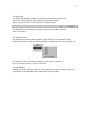
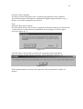
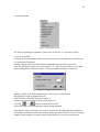
2.3 Starting/Ending a Session
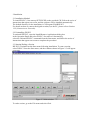
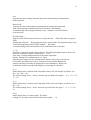
DX-PC3 is included on the Start menu following installation. To start a session,
select DX-PC3 from the Start menu, and the windows shown in Figure 2.3 will appear
on-screen.
Figure 2.3 Main window
To end a session, go to the File menu and select Exit.
8
3 Main Window: Display & Operation
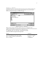
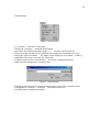
3.1 Main Image Field
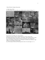
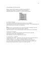
The main image field, in its multi-screen display mode, is shown in Figure 3.1-1.
Figure 3.1-1
In the multi-screen display, the camera number
changes from green to yellow to indicate the most recently updated field.
By clicking the primary mouse button (“left clicking” in the standard setting) within
any of the displayed image fields, the multi-screen display can be changed to a
single-screen display. Alternatively, by clicking the secondary mouse button (“right
clicking” in the standard setting) within
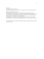
any of the displayed fields, the following menu can be accessed (Figure 3.1-2).
9
Figure 3.1-2
By selecting its number from the Assign list, any camera can
be assigned to the field position you have selected. The assigned camera number
gets saved in the registry, and will appear in that position at the start of the next session.
Note:
If the same camera number is assigned to more than one field
in the display, these fields will be updated at the same time and will show identical
images.
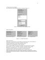
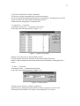
3.2 Operation Panel (Bottom)
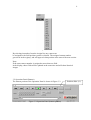
The bottom portion of the Operation Panel is shown in Figure 3.2.
Figure 3.2 Operation Panel (bottom portion)
Position slider (*1)
10
Each of the buttons appearing in the bottom portion of the Operation Panel has a
different function as described below. The Renew Info function can
also be accessed from the Network menu, and the other buttons canbe accessed
using commands found in the Operation menu.
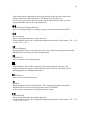
Rewind (Jump to Starting Position)
Moves to the beginning of a recording segment on the current connected DVR
Reverse Search
Starts search playback in the reverse direction.
Search playback speed can be adjusted through repeated clicks of this button. (1X -> 2X
-> 4X -> 8X -> 1X…)
Reverse Playback
Starts playback in the reverse direction. Also, starts skip reverse playback when Skip
Playback has been selected in the Operation menu.
Field Reverse
Moves to the previous field and stops.
Stop
Stops playback. If the audio command is ON, audio playback continues after
image playback has stopped. (Audio playback does not occur when Stop is used
during playback in communication mode.)
Field Advance
Moves to the next field and stops.
Playback
Begins playback in the normal direction. Also, starts skip playback when Skip
Playback has been selected in the Operation menu.This button
is also used to activate the PC playback software feature.
Forward Search
Starts search playback in the normal direction.
Search playback speed can be adjusted through repeated clicks of this button. (1X -> 2X
-> 4X -> 8X -> 1X…)
11
Live
Acquires the newest image from the operation camera during communication
mode operation.
Renew Info
Acquires the newest information regarding alarm, camera operation and
other factors during communication mode operation. (Information
is automatically renewed approximately every 3 minutes even if this button
is not pressed.)
Position slider
Appears when SCSI-connected devices are played back. (This slider does not appear
when
starting this software.) By dragging the mouse on the slider, the playback image is mo
ved to the designated position of the medium. This slider
is corresponding to the block number of the medium but not to the time.
1 – 16
Specifies a camera for single-camera display. For clicking multiple buttons, Press Ctrl
and click on desired camera’s number(s) (1 – 16) at
same time. Clicking multiple buttons will initiate sequential
display. During live communication (i.e., when
acquiring new images via the communication mode), only active cameras can
be selected; the buttons for inactive cameras will not respond. Buttons for
cameras currently recording are displayed in red. Furthermore, display can
be shifted to full-screen sequential display by canceling all selections.
2x2
Shifts display into 4-camera mode. Repeated clicks will cycle display as follows: 4a ->
4b -> 4c -> 4d -> 4a…
The initial settings for 4a – 4d are, from the top left field to the right: 1 – 4, 5 – 8, 9 – 12,
13 – 16.
3x3
Shifts display into 9-camera mode. Repeated clicks will cycle display as follows: 9a ->
9b -> 9a…
The initial settings for 9a – 9b are, from the top left field to the right: 1 – 9, 1 + 2 + 10 –
16.
4x4
Shifts display into 16-camera mode. The initial
settings are, from the top left field to the bottom right: 1 – 16.
12
Bookmark
Activates the bookmark function
saving the image into the PC’s memory. The image info is lost when PC is turned off.
Playback speed adjustment slider
By dragging the mouse on the slider underneath the buttons, playback speed can
be increased up or decreased down. Using “Fast” (the default setting), images from each
device will be renewed at the device’s maximum speed. “Slow”, on the other hand,
adds roughly a 3-second wait to each frame shown at
maximum speed. The slider provides 100 adjustment steps between Fast and Slow.
(A playback speed is adjusted by changing the transfer rate in the operation of internal. )
The Operation Panel can be displayed or hidden using the Information Panel command
in the View menu.
13
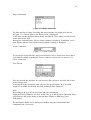
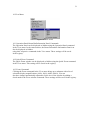
3.3 Information Panel (Right)
The left portion of the Information Panel is shown in Figure 3.3.
Figure 3.3 Information Panel (Right portion)
Media information
SCSI-connected device
Communication playback
Live communication
Figure 3.3.1 Media information
Media information
displays the connected-device name and the recorded time range of the medium in
use.During communication playback, displayed information
includes terminal name of the connected DVR, memo,
and the range of recording times. If the connected
device is in the middle of recording, the display will automatically be updated
approximately every three minutes to reflect the continuous change in data.
During live communication (i.e., the acquisition of the most current
images through the communication mode), the DVR information
displays the name of the connected DVR, memo, operation group, and
status (recording/playback/stop/timer/alarm). Information is automatically updated
(approximately) every three minutes, at which time image acquisition speed will drop
momentarily.
14
Image information
Figure 3.3.2 Image information
The date and time of image recording and camera number are displayed as shown
in Figure 3.3.2. During split-screen display mode, information
on the most recently updated camera image is displayed. This camera is marked in red
on the main image field.
During live communication, only the camera number is displayed. In addition, a red *
mark appears when a frame captured during alarm recording is displayed.
Zoom Combo box
Figure 3.3.3 Zoom Combo box
To activate the zoom function, single screen must be active. Zoom from 100 to 800 %
is possible.For details regarding the Zoom Combo box, please refer to Section 10.3
(Zoom Command).
Time Search
Figure 3.3.4 Time Search
Enter the desired date and time for your search in the text boxes, and click the Search
button. Images will
be displayed for the recordings made closest to the specified time. If no recorded
images are available for the date specified, nothing will be displayed.
Note:
Depending on the type of font used, date and time information
might not fit fully within the text box. In this case, go to the Windows Operation Panel,
select Region, and set the format of the date/time display to [MM/dd/yy] and
[HH:mm:ss].
The Information Panel can be displayed or hidden using the Information Panel
command in the View menu.
15
3.4 Status Bar
The Status Bar displays explanations of the selected menu or button, and
shows the current playback mode and the current display range.
Please refer to Section 3.6 (Hint Display) for further details
Figure 3.4 Status Bar
The Status Bar can be displayed or hidden using the Status Bar command
in the View menu.
3.5 Shortcuts Menu
By clicking the secondary mouse button (“right clicking” in the standard setting)
anywhere within the image, the following Shortcuts menu can be accessed (Figure 3.6).
Figure 3.6 Shortcuts menu
For details on each of the menu commands, please refer to Section 5.1
(Copy Command) and 10.3 (Zoom Command).
3.6 Hint Display
Placing the mouse pointer over the on-screen button will make two things appear: an
explanation in the Status Bar and a hint balloon near the pointer.
16
4 File Menu
Figure 4 File menu
4.1 Media… Command
Clicking the Media... command in the File menu opens the following dialog box
(Figure 4.1), which allows to select the media. (This function
works during playback of SCSI-connected device only.)
Figure 4.1 Media…dialog box
The following information is displayed in this box. The bender ID and the revision
can be acquired by sending the SCSI INQUIRY command.
HA
ID
LUN
VenderID
Revision
HostAdapter No.
SCSI ID
LUN No.
17
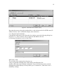
4.2 Save As… Command
Clicking the Save As… command in the File menu opens the following dialog box
(Figure 4.2), which allows the currently displayed image to be saved as either a
Windows bitmap file (.bmp) or an JPEG file (.jpg).
Figure 4.2 Save As… dialog box
When saving an image in Windows bitmap format, the recording time and
comments for that image get saved in an accompanying text file (.txt) of the same name.
When saving an image as an JPEG file, the image gets saved
as a JPEG file (.jpg) the same name. Comments are included
within the HTML file using the following format.
Format
Line 1: DX-PC3 version
Line 2: Recording date/time, frame number
Line 3: Camera #, alarm (A), alarm start (S)
Line 4: Comment
Comment
Mitsubishi DX-PC3
01-23-01 12:34:56’01
Camera: 2 ,AS
(COMMENT)
18
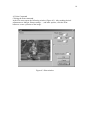
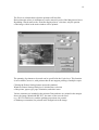
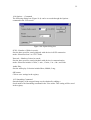
4.3 Print Command
Clicking the Print command
in the File menu opens the following window (Figure 4.3). After making desired
adjustments to Margin, Printer settings…, and other options, click the Print
button to create a printout of the image.
Figure 4.3 Print window
19
The Preview column shows what the printout will look like.
Desired margin values (in millimeters) can be entered in each of the Margin text boxes.
By adding a check mark to the “Print the displayed area” selection, only the portion
of the image visible in the main window will be printed.
The quantity of printouts to be made can be specified in the Copies box. This function
is not available, however, with printers that do not support printing of multiple copies.
Clicking the Printer Settings button opens the standard
Windows Printer Settings dialog box, which allows selection
of the printer, paper type, page orientation, and other items.
Various elements are included in the printout. Date and time are printed in the margin
above the image. Mitsubishi DX-PC3, the name of the recorder used
(e.g., DX-TL1600 Series), and the printing proportions (in portrait
or landscape orientation) are printed in the margin below the image.
20
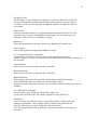
5 Edit Menu
Figure 5 Edit menu
5.1 Copy Command
The currently displayed image can be copied to the clipboard
by using the Copy command in the Edit menu.
21
6 Network Menu (DX-TL1600 only)
Remote control of the recorder(s) is possible using the DX-PC3
communication functions. For details on a general method of
connection, please refer to Section 12.2 (Connection to Networks).
Figure 6 Network menu
6.1 Connect Command
The Connect command in the Network menu allows you to establish a
connection to the recorder selected in the Recorder list window. This command does not
work if the Recorder list window is not displayed.
Note:
If connection to a recorder that has not yet started recording is attempted, operation
will halt in the middle of data acquisition. Before making a
connection, please be sure to confirm that the recorder contains some recorded data.
6.2 Disconnect Command
Connection to a recorder can be terminated using the Disconnect command
in the Network menu. This command does not
work when there is no active connection to a recorder.
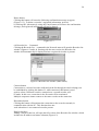
6.3 Add recorder… Command
Clicking the Add recorder… command on the Network menu opens the Recorder list
window (Figures 6.3, 6.3.1, and 6.4). Using this window, you can add
or remove recorders as well as edit saved settings. DX-PC3 allows registry of
up to 100 terminals. Starting with the next session, the Recorder list window will
automatically be displayed when a registered recorder is present.
22
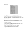
Figure 6.3 Recorder list window (full)
By using the mouse to drag the partition lines, each column on the list (DVR name, IP
address, memo) can be widened to display more characters.
6.3.1 Register/Add commands
Clicking the Add button on the Recorder list window opens the following dialog box
(Figure 6.3.1). New recorders can be registered and added to the list
by entering information in each of the fields.
Figure 6.3.1 Recorder Property box
DVR name: field
The recorder to be registered can be given an
easily recognizable terminal name. In the abbreviated Recorder list
window, this is the only field that is displayed. Up to 40 characters can be entered,
although the default display will only show up to 30 characters. (This field is not a
mandatory setting.)
23
IP-address: field
The IP address of the recorder to be registered is entered in this field. As DX-PC3
uses this information to establish connections with recorders, it must be entered
correctly to ensure normal operation. In addition, duplicate IP addresses will not
be accepted.
Memo: field
Comments for the recorder to be registered can be entered in this field. Up to 40
characters can be entered, although the default display will only show up to 30
characters. (This field is not a mandatory setting.)
OK button
Enters the information of the above fields in the Registered Terminals list.
Cancel button
Cancels the operation of regiatering/adding a terminal.
6.3.2 Connect/Disconnect commands
Connections to registered recorders can be made using the Recorder list
window (Figures 6.3 and 6.4). Connections to recorders that are currently recording can
also be made.
Connect button
Please refer to Section 6.4 (Recorder list Command).
Disconnect button
Please refer to Section 6.4 (Recorder list Command).
Details checkbox
Removing the check from this box hides the IP address and memo columns,
converting the Recorder list window to its abbreviated version
(Figure 6.4). In the abbreviated window, the Add, Edit, and Delete buttons are also not
included.
6.3.3 Edit/Delete commands
Saved settings can be edited and registered recorders can
be removed via the Recorder list window (detailed version, Figure 6.3).
Edit button
Click a selected recorder on the list to access that recorder’s Property box and
change its information. These changes will be reflected in the Recorder list
when the OK button is clicked. Using the Cancel button will
erase the changes made in the Property box, and these alterations will not be put
into effect.
24
Delete button
Clicking this button will cause the following confirmation message to appear
(Figure 6.3.3). To delete a recorder’s registered information, proceed
by clicking OK. Alternatively, using the Cancel button will remove the confirmation
message, and registered information will not be altered.
Figure 6.3.3
6.4 Recorder list… Command
Clicking the Recorder list… command in the Network menu will open the Recorder list
window (Figures 6.3 and 6.4). Starting with the next session, the Recorder list
window will automatically be displayed when a registered recorder is present.
Figure 6.4 Recorder list window (abbreviated)
Connect button
Connection to a selected recorder (indicated on the list through inverted coloring) can
be established by clicking this button. If, while connected, this button is used
again to select a different recorder, connection to a second recorder will
be made. In this case, connection to the first unit will be terminated.
Multiple computers cannot connect to the same recorder at the same time.
Disconnect button
Clicking this button will terminate the connection to the recorder currently in
communication with the PC. This function does not
work when there is no connected recorder present.
Details checkbox
Adding a check to this box will open the full version of the Recorder list window, which
includes the IP address and memo columns (Figure 6.3).
25
6.5 Renew info Command
The latest recorder information can be acquired using the Renew info command
in the Network menu. Information is automatically updated (approximately) every 3
minutes even if this command is not selected.
Note:
Automatic Disconnect function
The networking feature will activate its Automatic Disconnect function 30 minutes after
a connection to a recorder has been established, and a message box will be appear
on-screen (Figure 6.5.1).
Figure 6.5.1
If the Disconnect Now button is selected, the connection will be terminated
after two minutes and the following message will be displayed (Figure 6.5.2).
Figure 6.5.2
If the Continue button is selected, the connection will be sustained for another 30
minutes.
26
7 Search Menu
Figure 7 Search menu
7.1 Comment…/Find Next Commands
Clicking the Comment... command in the Search
menu opens the following window (Figure 7.1). Searches can be made for
a frame recorded with the specific comment by entering the text into the box and
clicking the Find Next button. The image is then displayed if it is found. If the Up
command of Direction is selected, the search will
be made towards earlier recorded times. The Down command performs a
similar function through later recording times.
Figure 7.1 Find window
Clicking the Find Next in the Search menu starts the search of the comment which
is designated in Comment... command. This function does not
work during the communication mode.
27
7.2 Previous Alarm/Next Alarm Commands
The Previous Alarm command in the Search menu starts a
search for Alarm Recordings through earlier recorded times, and displays the field if
any are detected. The Next Alarm command performs a
similar function through later recording times.
7.3 Alarm List… Command
Clicking the Alarm List… command on the Search
menu opens the following window (Figure 7.3).
Figure 7.3 Alarm List window
Display can be moved to a desired alarm position
by selecting the alarm time from the list box and clicking the Search
button. A tab-sectioned text file of the alarm list can be made by clicking the Save…
button.
7.4 Time… Command
Clicking the Time… command in the Search
menu opens the following window (Figure 7.4).
Figure 7.4 Time Search
Searches can be made for a frame recorded at a
specific time by entering the date and time in their respective text boxes and
clicking the Search button. The image is then displayed if it is found.
28
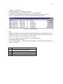
7.5 Block… Command
Clicking the Block... command in the Search
menu opens the following window (Figure 7.5). Searches can
be made by selecting the desired block from the list box and clicking the Seach
button. This function does not work during the communication mode.
Figure 7.5 Block Search
Note:
When accessing from peripheral devices with large amount of recording blocks such
as DDS-2 or DDS-3 to a PC with a slow CPU or a small amount of on-board memory, it
may take a long time to open the Block search window.
The list box contains the block number, its recording start time,
its recording end time, the flag,
and the camera number. The following table indicates symbols used in the flag field
and their meanings.
Flag
A
S
C
T
Meaning
Contains an alarm-recorded frame
Contains an alarm-recording start frame
Contains a comment-recorded frame
Contains a shot-recording frame
29
8 Operation Menu
Figure 8 Operation menu
For details regarding the Operation, please refer to Section 3.2 (Operation panel) .
8.1 Eject Command
Clicking the Eject command in the Operation menu Ejects the media from SCSI devise
8.2 Skip mode Command
Adding a check mark to the Skip Mode command in the Operation menu will
open the following window on-screen.(Figure 8.2) This feature comes in very handy
when playing back a medium used for a recorder without multiplexer functions.
Figure 8.2 Skip mode window
Adding a check to the Skip Mode checkbox allows the recorder to start
skip playback at the designated interval.
In the Number of Field to Skip, the number of
cameras used for recording in the medum can be set.
Clicking
or
button of Camera Select will
switch the images to the designated camera during playback.
This function can be used only when active cameras are fixed through the multiplexer.
Set Number of Field in SCSI of the Options dialog box (See Section 10.4) to an integral
multiple of the number of cameras when using forward or reverse search function.
30
9 Bookmarks Menu
Figure 9 Bookmarks menu
9.1 Marking using bookmark Command
Current playback position can be registered on the bookmarks list
by using the save with bookmark command in the Bookmarks menu. Up to 30
bookmarks can be registered. When this limit is exceeded, bookmarks will be erased
starting with the oldest bookmark. All bookmarks are erased when the DX-PC3 session
is ended. This command has the same function as the Bookmark button
on the Operation Panel.
9.2 Bookmarks quick search Command
Marked bookmarks image can be transferred selecting the Bookmarks list(1-30)
in the Bookmarks menu.
9.3 Bookmarks A, B Command
Using the Bookmarks A, B command in the Bookmarks menu, the current position can
be stored as either the A-point or B-point for the Repeat between A and B function.
9.4 Repeat between A and B Command
By adding a check mark to the Repeat between A and B command
in the Bookmarks menu, repeat playback will
be performed from the specified A-point to the specified B-point
when pressing Playback button.
31
10 View Menu
Figure 10 View menu
10.1 Operation Panel/Status Bar/Information Panel Commands
The Operation Panel can be displayed or hidden using the Operation Panel command
in the View menu. In the same manner, the Status Bar and the Information Panel can
also be displayed or hidden
using their respective commands in the View menu. These settings will be saved
in the registry.
10.2 Quick Zoom Command
The Quick Zoom window can be displayed or hidden using the Quick Zoom command
in the View menu. This setting will be saved in the registry.
10.3 Zoom Command
Clicking the Zoom command in the View menu brings up a submenu with a list of
selectable display magnifications (100%, 200%, 400%, 800%). You can
also have images automatically adjusted to fit the size of the window by adding a
check mark to the Fit-to-window command. These settings will be saved in the registry.
32
10.4 Options… Command
The following dialog box (Figure 10.4) can be accessed through the Options…
command in the View menu.
Figure 10.4 Option dialog box
SCSI---Number of fields in search:
Sets the base speed for search playback with devices in SCSI connection
mode. Selections from 2 to 32767 fields.
Network---Number of times in search:
Sets the base speed for search playback with devices in communication
mode. Selections include 0.5 min., 1 min., 15 min., 1 hr., 4 hr., and 24 hr.
Audio Play:
Sets the audio play. Selection include Short, Middle, Long.
OK button:
Click to save settings in the registry.
10.5 Smoothing Command
Smooth display of the stopped image can be obtained by adding a
check mark to the Smoothing command in the View menu. This setting will be saved
in the registry.
33
10.6 Audio Command
Adding a check mark to the Audio command
in the View menu outputs the audio when plying back the audio-recorded
medium. Stopping the image playback starts the audio for several seconds before and
after the stopped frame.
3 levels of audio settings (short/middle/long) are available.
Note:
The audio playback period
will vary depending on the recording settings (recording interval/recording image qualit
y) etc. of the medium.
10.7 Camera Command
Figure 10.7 Camera commands
When performing media playback from a
unit that has the multiplexer function, the Camera command
in the View menu lets you select the playback camera.
- Selecting ALL initiates sequential playback of all cameras.
- Selecting any other option will add that camera to the group of
cameras currently playing.
34
11 Help Menu
Figure 11 Help menu
11.1 Help Command
Help can be displayed by selecting the Help command in the Help menu.
11.2 About… Command
Information on the version of DX-PC3 being used can be accessed through the About…
command in the Help menu.
35
12 Appendices
12.1 Restrictions
- The playback speed of DX-PC3 is determined by the host
computer’s processing speed and the type of playback devices used. (When
operating in communication mode, it will also be affected by the amount
of network traffic and other factors.) For these reasons, there will
be cases where the software’s playback speed does not
match the recording intervals of the digital recorder.
- Depending on the condition of the DVR recording (for example, if
date and time information are in reversed order),
there may be instances when playback, searches and other functions cannot
be correctly performed.
- Depending on the printer or the printer driver
used, there may be instances where images and/or text data do not get printout out
correctly.
- DX-PC3 consumes a large amount of memory in order to display and
update image data. Please avoid running other
application programs while using DX-PC3.
- The DVR’s Lock function is activated during communication mode,
which halts use of the RS-232C terminal and
other functions. To cancel the Lock function,
disconnect the recorder’s Communication function via the DX-PC3
disconnect function..
- The quality of the images displayed by DX-PC3
depends on the image quality settings used by the recorder at the time of recording.
Other factors, however, will also affect quality when images are displayed at over
100% magnification.
36
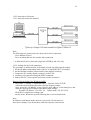
12.2 Connection to Networks
12.2.1 Network connection method
The following diagram depicts a general method for connecting the recorder to a LAN.
Note:
The following two points need to be observed for LAN connection.
- Use a dedicated LAN.*
- Use a switching hub for the recorder-side connection.
* A dedicated LAN is a network comprised of DVR(s) and a PC only.
12.2.2 Settings for the LAN connection
The procedure is outlined below, with details of each step following the outline.
1. Set the IP address and subnet mask of the PC in which DX-PC3 is installed.
2. Set the IP address and the subnet masks of the digital recorder(s).
3. Connect the PC and the digital recorder(s) to the LAN.
4. Confirm LAN connection using the PING command.
5. Start up DX-PC3, then register and connect to the recorder(s).
Details of the procedure (for Windows 98SE)
1. Go to Start -> Settings -> Operation Panel -> Network. Select TCP/IP
within the Network dialog box, then click the Property button.
Next, select the “ IP address” select “Specify an IP address” in the dialog box, and
make the appropriate IP address and subnet mask settings.
Example: IP address: 192.168.1.101 Subnet mask: 255.255.255.0
Click OK to complete the settings, and
exit the menu. Restart the system following the on-screen instructions.
Note:
IP addresses and subnet masks must be set correctly. Do not make (or
alter) these settings if you do not have sufficient expertise on networks.
37
2. Turn the recorder’s main power ON, and set the recorder’s IP address and subnet
mask. For detailed
instructions on how to do this, please refer to the user’s manual provided
with the recorder. Factory default settings for the recorder are as follows:
IP address: 192.168.1.100 Subnet mask: 255.255.255.0
These strings can
be used provided there are no duplicate settings within the same network.
Note:
The IP addresses 192.168.1.xxx (1 – 254) fall within the range of private IP
addresses prescribed for RFC1918. Please use this range if it
does not potentially cause any problems to do so.
3. As shown in the diagram above, use LAN cables and a
switching hub to connect recorders to the network. If only one recorder
is being connected to one PC, a cross cable can be used and the switching hub can
be omitted.
4. Go to the Start menu and open MS-DOS Prompt. Enter ping_192.168.1.100
(the number string corresponding to the recorder’s IP address), and press the Return
key. Initiating the PING command will cause the recorder’s Receive indicator
and Transmit indicator to illuminate for a moment, and the following message will
be displayed:
Pinging 192.168.1.100 with 32 bytes of data:
Reply from 192.168.1.100: bytes=32 time<10ms TTL=255
:
:
If the recorder is not correctly connected, a “time out” message such
as the one below will appear. Please refer to the troubleshooting section
(14.3.3) to check the connection.
Pinging 192.168.1.100 with 32 bytes of data:
request timed out.
:
:
5. Start up DX-PC3 and register the recorder in accordance with the steps specified
in this user’s manual.
38
12.2.3 Troubleshooting – Please refer to the following if problems occur
during network connection procedures.
Please check each of the following items (a – h).
a) Confirm that the cable is physically connected.
Check to see that the connection has not been made to the hub’s cascade port. Recent
connectors feature a guard that makes it
difficult to insert them all the way into the recorder; check to see that the connector
is all the way in.
b) Check the IP addresses and the subnet masks of the PC and the recorder(s).
Check that the network address segments correctly match up. Confirm that the host
address segments are unique. Confirm that settings are not
identical to other network terminals or IP addresses.
c) Confirm that the IP address entered using PING is correct.
Do not enter zero (e.g., 001). Be sure to enter a space between “ping” and the IP
address.
d) Change cables.
e) Restart the PC and the recorder(s).
The switching hub address gets entered into memory as a result
of the restarting process.
f) Leave the connected units alone for a little while with their power ON.
Depending on the type of switching hub used, there are instances where the IP
address of a new device is not recognized. Leave the units alone for an
extended period of time (over 20 minutes), and check their condition after this.
g) Replace the switching hub.
h) Test the computer’s Ethernet card.
Enter 127.0.0.1 in the PING utility and press the Return key. If a
correct response is not returned (i.e., the device manager does not show “!” or “?”),
check to see that the Ethernet card driver software is installed properly.
Please remove the driver for the Ethernet card once, and then reinstall it.