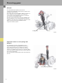
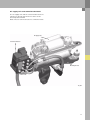
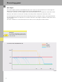
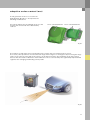
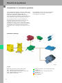
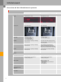
1
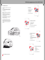
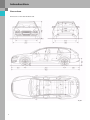
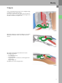
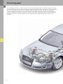
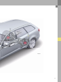
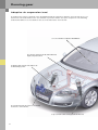
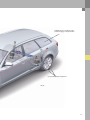
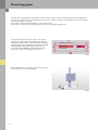
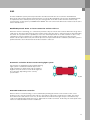
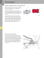
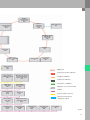
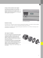
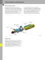
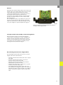
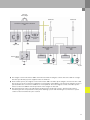
344
Vorsprung durch Technik www.audi.de
Service Training
The New Audi A6 Avant ´05
Self-Study Programme 344
All rights reserved.
Technical specifications
subject to change without
notice.
Copyright
AUDI AG
I/VK-35
[email protected]
Fax +49-841/89-36367
AUDI AG
D-85045 Ingolstadt
Technical status: 02/05
Printed in Germany
A05.5S00.13.20
Self-study programmes on the Audi A6 Avant
The New Audi A6 Avant ‘05
Audi is adding a new chapter to the success story of
the Avant.
The new Audi A6 Avant '05 represents a unique
blend of design and dynamism, driving pleasure
and functionality.
SSP 323 Audi A6 ´05
–
–
–
–
Here is a car that exhibits a unity and harmony of
design.
Measuring 4.93 metres in length, 1.86 metres in
width, and 1.46 metres in height, the new
Audi A6 Avant ´05 visibly sets a new standard in
terms of its proportions.
The lines of the car combine the clear architecture
typical of Audi with other core elements of the
brand's progressive design.
Introduction to the vehicle
Body engineering
Occupant protection
Air conditioning
Order number: A04.5S00.06.20
323_057
The already classic proportions of the Avant's
silhouette, with its high shoulder line, narrow
windows all round, coupé-like roofline and shallow
sloping tail end, have been infused with added
dynamism.
SSP 324 Audi A6 ´05 Running Gear
–
–
–
–
–
Front axle technology
Rear axle technology
Steering system
ESP
Electromechanical Parking Brake EPB
Order number: A04.5S00.07.20
323_058
SSP 325 Audi A6 ´05 Engines and
Transmissions
344_057
–
–
–
–
–
3.0 V6 TDI Common Rail
3.2 V6 FSI
Manual transmissions 01X, 02X, 0A3
6-step automatic transmission 09L
Multitronic 01J
Order number: A04.5S00.08.20
323_059
SSP 326 Audi A6 ´05 Electrical Systems
–
–
–
–
344_056
Networking
Bus topologies
Convenience electronics
Infotainment
Order number: A04.5S00.09.20
Into the lead: With Design & Performance
323_056
Table of contents
Introduction . . . . . . . . . . . . . . . . . . . . . . . . . . . . . . . . . . . . . . 4
Body . . . . . . . . . . . . . . . . . . . . . . . . . . . . . . . . . . . . . . . . . . . . 5
Occupant protection . . . . . . . . . . . . . . . . . . . . . . . . . . . . . . 6
Engine . . . . . . . . . . . . . . . . . . . . . . . . . . . . . . . . . . . . . . . . . . . 8
Running gear. . . . . . . . . . . . . . . . . . . . . . . . . . . . . . . . . . . . 12
Electrical systems . . . . . . . . . . . . . . . . . . . . . . . . . . . . . . . . 26
Infotainment . . . . . . . . . . . . . . . . . . . . . . . . . . . . . . . . . . . . 30
Convenience electronics . . . . . . . . . . . . . . . . . . . . . . . . . . 32
The self-study programme provides introductory information regarding the design and function of new
models, automotive components or technologies.
The self-study programme is not a Repair Manual!
All values given are intended as a guideline only and refer
to the software version valid at the time of publication of the SSP.
For maintenance and repair work, always refer to the current technical literature.
Reference
Note
Introduction
Overview
Dimensions of the Audi A6 Avant ´05.
344_062
4
Body
Tailgate
In the new Audi A6 Avant ´05, an inner tailgate hinge
is implemented for the first time.
The hinge is attached to the upper roof crossrail at
the rear so that it is located behind the tailgate seal,
and thus inside the occupant cell.
344_046
When the tailgate is closed, the hinge is concealed
behind the trim panel and is not visible from the
interior.
344_047
This hinge arrangement and function has the
following advantages:
– no corrosion,
– no sealing problems,
– internal wiring,
– no grommets are needed to seal through-holes
in the body,
– larger cargo area
possibility for electric tailgate drive.
344_048
5
Occupant protection
Safety system
The goal was to implement a protection system that offers a very high level of safety, thereby raising still
further the high safety standard set by the current Audi fleet.
The many safety requirements for the new Audi A6 Avant ´05 included meeting all current legislation, as well
as achieving a top rating in consumer tests.
Audi's internal specifications often increase the challenges to the development team.
This was the case with the Audi A6 saloon introduced to the market in the 2005 model year; likewise with the
new Audi A6 Avant ´05.
The occupant protection system in the Audi A6 Avant ´05 was largely adopted from the saloon. Due to the
modifications to the body, however, several components were adapted to the new parameters.
A new gas generator with dual threshold deployment for the front passenger front airbag will be implemented
in the Audi A6 saloon in early 2005. This module will be fitted to all models world-wide.
The new Audi A6 Avant ´05 will be equipped with this airbag from rollout.
Reference
For further information on the safety
system, please refer to Self-Study
Programme 323 - Audi A6 ´05.
Front passenger front airbag
– Airbag igniter 1, front passenger side N131
– Airbag igniter 2, front passenger side N132
The front passenger airbag consists of a casing in which are housed two pyrotechnic gas generators
separated by a partition. A propellant in the form of tablets and hollow tabs is used.
Outlets
Rupture disc
Priming charge 2
Rupture disc
Metal filter
Partition
Metal filter
Priming charge 1
Igniter 2
Igniter 1
Housing
344_001
Metal filter
Propellant charge 2
Compensating material
Outlets
6
Propellant charge 1
Metal filter
Airbag igniter 1, front passenger side N131
If igniter I is electrically activated by the airbag control unit J234, it ignites priming charge I. Under the
resulting pressure, the flame passes through the rupture disc and ignites propellant charge I.
On account of the hollow propellant tabs, the complete propellant charge ignites more quickly.
The metal filter cools and treats the developing gas before it flows through the outlets to the airbag.
The task of the first gas generator is to inflate the airbag.
Partition
Metal filter
Outlet
Rupture disc
Igniter I
344_004
Compensating material
Outlet
Propellant charge 1
Metal filter
Airbag igniter 2, front passenger side N132
The airbag control unit defines the time interval between the deployment of airbag igniter 1, front passenger
side N131 and airbag igniter 2, front passenger side N132 according to the type and severity of the accident.
The task of the second gas generator is to inflate the airbag to its full size.
The second gas generator has exactly the same function as the first gas generator.
Igniter 2
Rupture disc
Outlet
Priming charge 2
Metal filter
Partition
344_005
Housing
Propellant charge 2
Outlet
Compensating material
Metal filter
7
Engine
The 2.7l V6 TDI with common rail
The 3.0l V6 TDI was modified in several respects to
fill the gap between the 2.5l V6 TDI with distributor
injection pump and the 3.0l V6 TDI with common rail
injection. A wide range of diesel engines in various
sizes is therefore available to the customer.
344_011
8
The engine number is located on the cylinder block
at the front right adjacent to the vibration absorber.
Torque/power curve
Max. torque in Nm
Max. power output in kW
Engine speed in RPM
344_012
Specifications
Engine code
BPP
Type of engine
V6 diesel engine
Displacement
2698 cm3
Power output
132 kW (180 bhp)
Torque
380 Nm at 1400-3300 rpm
Bore
83 mm
Stroke
83.1 mm
Compression ratio
17:1
Weight
220 kg
Firing order
1-4-3-6-2-5
Engine management
Bosch EDC-16CP+ common rail injection system
with max. 1600 bar operating pressure and 8-port piezo injectors
Exhaust emission control
Oxidising catalytic converter, maintenance free diesel particulate filter
(optional), lambda probe and cooled exhaust gas recirculation
Exhaust emission standard
EU 4
9
Engine
Modifications to the 2.7l engine
– The stroke was reduced from 91.4 mm to
83.1 mm by modifying the crankshaft, con-rod
and piston
– Cast exhaust manifold and steel compensator
without air-gap insulation
– Deletion of the shield plates above the manifolds
– Piezo injectors with eight-port nozzles instead of
seven-port nozzles
– An inlet restrictor has been integrated into the
fuel rail for each injector
Crankshaft drive
The basis is the 3.0l V6 TDI CR engine, i.e. the engine
block with 90 mm cylinder spacing was adopted,
likewise the 83.0 mm cylinder bore.
The crankshaft, the con-rod and the pistons were
modified so that a swept volume of 2698 cm3 was
obtained by changing the stroke.
344_003
10
In-rail restrictor
The closing of the injector produces a pulse which
propagates from the injector to the fuel rail and is
reflected back to the injector. In this connection, the
injector pintle and injector pintle seat are subjected
to a high mechanical load (bounce). A restrictor is
installed upstream of each injector to dampen the
pulses in the fuel rail. This restrictor dampens the
incoming and outgoing pulses and so prevents the
injector pintle from colliding with the injector pintle
seat.
The restrictor is mechanically press-fitted into the
fuel rail.
to injector
Fuel line
Inlet restrictor
Rail
344_061
Piezo injector
To reduce particulate emissions still further and to
optimise combustion, 8-port injectors are used in
place of 7-port injectors. This enables the fuel to be
more finely atomised and provides a smoother
combustion process.
Note
When replacing the injector, pay attention
to the genuine parts number!
11
Running gear
A steel-spring suspension is used in the basic version of Audi A6 Avant `05. In comparison with the running
gear in the A6 saloon, the set-ups for the springs, dampers and anti-roll bars have been revised. In the Avant,
too, there are suspension systems for front-wheel-drive and quattro versions. The dynamic suspension
system is available in the basic version. A sport suspension, which lowers the overall car's ride height by
15 mm compared to the dynamic suspension system, is available as an optional extra. Heavy-duty running
gear, which raises the car's ride height by 15 mm compared to the dynamic suspension system, is also
optional.
12
344_029
13
Running gear
Adaptive air suspension (aas)
A modified aas system is optional in the Audi A6 Avant `05. By comparison with the aas in the A8, there is no
distinction to be made between the aas standard suspension and the aas sports suspension. The following
fundamental differences exist between the aas in the A6 and the aas in the A8:
aas is also available in combination with MMI Basic
the control was adapted for the A6, with modified ride
heights compared to the A8
modified mechanical design of the dampers and
modified damping control
the solenoid valve block and compressor are installed
mounted on a common bracket
body acceleration senders are integrated in the wheel arch
14
modified pressure accumulator design,
mounted to luggage compartment floor
separate spring/damper arrangement
344_030
15
Running gear
Dampers
The Audi A6 Avant ´05 with aas also has
continuously adjustable rebound and compression
damping characteristics.
The front and rear axle dampers differ in respect of
their design from the dampers on the A8. The
electrically activated damping valve is located on
the exterior of the damper tube.
For this reason, and also because the dampers for
the A8 and A6 are sourced from different systems
suppliers, we refer to the suspension system on the
A6 as a Continuously Controlled Electronic
Suspension (CES) system.
Damping valve
344_017
Separation of the rear axle springs and
dampers
The advantages of this configuration are an
optimised through-loading width and low boot
floor. A boot protects the complete air spring
against ingress of dirt. Due to the size of the air
springs, no additional air volume is required, which
is the case with the A8 D3. The boot can be replaced
by a service workshop.
A new aluminium trapezoidal link was developed for
the aas.
New aluminium trapezoidal link
344_014
16
Air supply unit and solenoid valve block
The air supply unit and the solenoid valve block are
identical in design and function to those of the
allroad quattro and A8.
Both units are now mounted on a common bracket.
Air supply unit
Solenoid valve block
Mounting bracket
344_007
17
Running gear
Ride heights
The modes implemented in the Audi A6 Avant ´05 are the same as in the A8. However, the ride heights are
different. The following conditions apply to the aas in the Audi A6 Avant ´05:
In "dynamic" mode, the car's ride height is lowered permanently by 15 mm compared to "automatic" mode.
When the "lift" mode is selected, the car body is raised by 15 mm compared to "automatic" mode.
The lowering of the suspension by 15 mm at motorway speeds in "automatic" mode is also implemented in
the Audi A6 Avant ´05. In the A6, there is no further reduction in ride height in "dynamic" mode, which is the
case in the A8.
The same conditions as on the A8 must be met in order to select and quit the various modes.
Reference
For further information, please refer
to the current operating instructions
and SSP 292.
aas modes in the Audi A6 Avant ´05
"lift"
"comfort"
"dynamic"
"automatic"
+15 mm
0 mm
-15 mm
0
100
120
kph
344_032
18
System failure response
If the electrical damping valve is deenergised in
case of failure, a default damping force
characteristic takes effect. In this case, the damper
works like a conventional (non-controlled) damper.
Damper set-up
Damping force (N)
Damping valve deenergised
Rebound damping
0
Compression damping
Speed m/s2
344_020
aas with MMI Basic
The aas system is available in the Audi A6 Avant ´05
in combination with MMI and also, alternatively, in
combination with MMI Basic .
344_027
19
Running gear
New special tools
The following new special tools are used for aas in
the Audi A6 Avant ‘05:
T 40082/1-6 spring blocker for air springs
Due to the modified installation dimensions, the
spring blockers used for the A8 are unsuitable for
the A6. The advantage of using spring blockers on
the A6 front axle is that subsequent replacement of
the upper transverse rods is no longer needed.
344_018
T 40081 ramp
When the system is fully vented , the suspension
will be so low that, in case of unfavourable
dimensional tolerances, a car jack cannot be used.
In such case, the vehicle is driven up onto the 8 cm
high ramps. A car jack or an auto-hoist can then be
used.
A new test adapter with the type designation
VAS 1598/53 is used for the air spring control unit.
20
344_016
adaptive cruise control (acc)
A new generation of the acc is used in the
Audi A6 Avant `05. This acc incorporates the
following modifications:
the exterior dimensions and weight of the acc unit
(sender and control unit) were substantially
reduced.
Sensor / control unit in the A8
Sensor / control unit in the A6
344_015
The number of radar transceivers integrated into the sender was increased from three to four.
As a result, it was possible to increase the beam angle from 8 degrees to 16 degrees. By increasing the range
of the sensor, objects in the path of the vehicle can be detected earlier. The maximum range of the object
detector was increased to 180 metres from 150 metres. The acc functionality was significantly improved with
regard to lane-changing and winding country roads.
180 m
344_033
21
Running gear
A heater was integrated into the bumper insert in front of the sender. It effectively prevents the build-up of
snow or ice on the surface of the bumper in front of the sender in wintry road conditions. As a result, higher
system availability is assured.
The heater is powered by the adaptive cruise control unit.
The heater is switched on and off in dependence on the ambient temperature.
The dynamic response of the vehicle in acc mode
under acceleration and under braking can now be
adapted to suit the driver's preferences by selecting
a driving program in addition to the distance setting
function. Three different driving modes can be
activated with the MMI (for detailed information,
refer to the current operating instructions).
Car
adaptive cruise control
Gong volume
Driving mode
medium
comfort
344_021
Rough adjustment is no longer required for setting
the sender in the service workshop.
344_058
22
ESP
The Bosch 8.0 ESP system previously featured in the A6 saloon will also be used in the Audi A6 Avant
`05.Several new functions will be implemented for use of the Bosch 8.0 ESP system in the Audi A6 Avant ´05.
To implement these auxiliary functions, the processing power of the ESP control unit was enhanced by
increasing the clock frequency to 60 MHz from 48 MHz. The new control unit will also be rolled out at the same
time in the A6 saloon.
Modified hydraulic brake assistant control for vehicles with acc
When the vehicle is travelling, acc continuously monitors objects in front of the vehicle within the range of the
radar sensor. The object detection function remains active even after the acc function has been deactivated by
the driver. The system has the capability to assess the "hazard potential" of a traffic situation. It does so by
evaluating a variety of parameters, including the number, position and speed of objects detected, the
distance to the objects detected, own vehicle speed etc.If a "potential hazard" is identified, the brake system is
prefilled and the cut-in threshold of the brake assistant is reduced.
Automatic activation of the hazard warning light system
If the brakes are applied hard, the hazard warning
light system is activated automatically to alert
traffic following on behind. On vehicles with the
Highline trim, the surfaces of the brake lights are
also enlarged, depending on the country
specification.
344_040
Extended understeer correction
When a vehicle is understeering, it can be stabilised by braking the wheels on the inside of the corner.
However, if the cornering speed of the vehicle is too high to achieve the required curve radius, this action
alone will not be sufficient. In such case, all four wheels are braked and engine torque is simultaneously
reduced. A slightly higher brake pressure is applied to the inside rear wheel. In this way, the road speed of the
vehicle is reduced and the vehicle is stabilised.
23
Running gear
Automatic stabilisation of the car-trailer combination
Slight swinging movements of a trailer can amplify
in such a way as to cause a critical driving situation.
This situation usually occurs at road speeds
between 75 and 120 kph.
If the trailer begins to swing when the vehicle is
travelling at a speed above the critical threshold, the
oscillation amplitude of the trailer will progressively
increase. The only way to reduce the swinging of the
trailer is to reduce speed to below the critical
threshold.
344_038
The swinging movements also excite periodic
oscillation of the towing vehicle about its vertical
axis. These yaw movements are monitored by the
yaw rate sender and evaluated by the ESP control
unit. If defined limits are exceeded, the ESP control
unit instructs the engine control unit to reduce
torque in order to slow the vehicle down. If this
action is insufficient, all four wheels are braked
simultaneously by the ESP control unit.
Enhanced acc braking comfort
On vehicles with acc, two additional pressure
sensors are installed in the lines between the ESP
unit and the front-axle brake calipers. The previous
method, whereby the actual brake pressure was
calculated in the control unit, is less accurate than
the direct measurement method, particularly at low
brake pressures. Using the data supplied by the
pressure sensors , ESP can control the build-up of
brake pressure more precisely. This results in
shorter reaction times, and braking becomes more
comfortable.
344_041
Brake pressure sensor
24
Notes
25
Electrical systems
Bus topology
Distance control
J428
In comparison with the A6 saloon, the bus topology
was extended only to include the tailgate control
units in the convenience CAN bus. The tailgate
control unit is explained in detail from page 32.
Control unit with display
in dash panel insert
J285
Diagnosis connection
T16
Databus diagnosis
interface
J533
Park assist
J446
NOx sensor
J583
Engine electronics 1
J623
Driver door control
unit
J386
Energy
management
system
J644
Yaw rate sender
G202
ABS with EDL
J104
Front passenger door
control unit
J387
Additional heater
control unit
J364
Seat occupied
recognition control
unit
J706
Airbag
J234
Rear left door control
unit
J388
Tailgate control unit
J605
Automatic gearbox
control unit
J217
Rear right door
control unit
J389
Onboard power
supply 2
J520
Headlight range
control, control unit
J431
Seat and steering
column adjustment
control unit with
memory
J136
Entry and start
authorisation control
unit
J518
Electric park and
handbrake control
unit
J540
Seat adjustment
control unit with
memory, front
passenger
J521
Onboard power
supply
J519
Adaptive suspension
control unit
J197
Trailer detector
control unit
J345
Convenience system
central control unit
J393
Steering column
electronics control
unit
J527
Climatronic control
unit
J255
Multi-function
steering wheel
control unit
J453
Tyre pressure
monitor control unit
J502
Power output module
for left headlight
J667
Power output module
for right headlight
J668
Wheel angle sender
G85
26
Telephone
transmitter and
receiver unit
R36
Telephone /
telematics
control unit
J526
Front information
control unit
J523
Telephone handset
R37
Navigation system
with CD drive
control unit
J401
TV tuner
R78
CD changer
R41
Digital sound
package control unit
J525
Radio module
R
Language input
control unit
J507
Tailgate control
unit 2
J605
MOST bus
Instrument cluster CAN bus
Entry and start
authorisation switch
E415
Antenna reader unit for
entry authorisation for
keyless entry system
J723
Diagnosis CAN bus
Powertrain CAN bus
Convenience CAN bus
Wiper motor
control unit
J400
Rain and light
detector sensor
G397
Adaptive cruise control CAN
bus
LIN bus
Interior monitoring
sensor
G273
Fresh air blower
control unit
J126
Transmitter unit,
front left
G431
Alarm horn
H12
Various subbus systems
Wireless transmission
- Bluetooth signal
Refrigerant pressure/
temperature sender
G395
Transmitter unit,
front right
G432
Transmitter unit,
rear left
G433
Transmitter unit,
rear right
G434
Rear antenna
R96
344_009
27
Electrical systems
Immobiliser in automatic gearbox
In the Audi A6 Avant '05, the automatic gearbox was
integrated into the immobiliser. This is the case with
both 6-speed automatic gearbox 09L and
multitronic gearbox 01J. With model year '06 or
later, the automatic gearboxes in the A6 saloon and
in the A8 will also have an immobiliser function.
The immobiliser still has the type designation
"Immobiliser 4", because it uses the same
technology as in the A8 '03.
These gearboxes have a control unit which is
integrated into the gearbox (mechatronics). The
relatively sophisticated, and hence secure,
installation location serves as a deterrent to parts
theft. Because engagement for power transmission
is dependent on the gearbox control unit, this
immobiliser offers good protection against vehicle
theft.
Immobiliser topology
J518
J533
E415
J623
J217
344_013
Legend
E415
J217
J518
J533
J623
28
Entry and start authorisation switch
Automatic gearbox control unit
Entry and start authorisation control unit
Databus diagnosis interface
Engine control unit
Component which is not integrated into the
immobiliser
Component which is integrated into the
immobiliser
Master control unit
PC / mainframe
Matching
The procedure for matching the gearbox control
unit is similar to the procedure for matching the
engine control unit.
The immobiliser still has the type designation
"Immobiliser 4", because it uses the same
technology as in the A8 '03.
Furthermore, the gearbox is able to accept a new
identity. If a key is stolen and the complete key set is
replaced, all control units integrated into the
immobiliser can assume a new identity.
Response to non-matched control unit
If only the gearbox control unit is not matched, can
the engine can be started in the usual fashion. The
gearbox control unit detects the missing or false
immobiliser information. This is indicated to the
driver by an inverted selector lever position
indicator on the centre display of the dash panel
insert. If a new control unit is used, the vehicle can
be operated in an emergency mode with a
maximum speed of approx. 20 kph, provided that
the control unit has not previously been matched to
any other vehicle.
If the control unit has already been installed in
another vehicle, emergency operation will not be
possible. The selector lever can be engaged by the
driver. However, the control unit will prevent tractive
power from flowing to the output shaft. As with
other immobiliser components, it is only possible to
match such a control unit in a vehicle of the same
model, i.e. a gearbox which has already been
matched to an A8 cannot be matched to an A6.
Gearbox modifications
multitronic
The 01J gearbox has no mechanical emergency
running mode. The modifications to the immobiliser
relate only to the software and certain electronic
components in the gearbox control unit.
325_071
6-speed automatic gearbox
In the case of the 09L and 09E gearboxes, the
hydraulic control unit was modified in addition to
the software and the hardware so that there is no
power transmission when deenergised. To achieve
this, the characteristics of several electric pressure
control valves have been inverted.
325_051
29
Infotainment
Overview of the infotainment systems
MMI basic
MMI basic plus
Standard equipment
Display
Monochrome 6.5" screen
Monochrome 6.5" screen
Control panel
4-key control panel
4-key control panel
Operating and display unit
control unit
In the glove compartment
– incl. radio module
– incl. audio single CD drive
– incl. 2x20W amplifier
for 4 loudspeakers, front
In the glove compartment
– incl. radio module
– incl. audio single CD drive
Amplifier
Integrated into the operating and display
unit control unit
DSP sound system with 160 W total power
output in the luggage compartment, rear left,
for 10 loudspeakers
Radio
Radio with diversity radio antenna,
integrated into the operating and display
unit control unit
Radio with diversity radio antenna and TP
memory function, integrated into the
operating and display unit control unit.
On the 4-key control panel, the TP memory
function can be selected via the radio set-up.
CD drive
Integrated into the operating and display
unit control unit
Integrated into the operating and display
unit control unit
Navigation
_
_
CD changer
CD changer in the glove compartment
CD changer in the glove compartment
Mobile phone preparation
Bluetooth mobile phone preparation
integrated into the centre armrest
incl. 8-key control panel
Bluetooth mobile phone preparation
integrated into the centre armrest
incl. 8-key control panel
BOSE amplifier
_
BOSE 6000 amplifier with
– BOSE Audi-Pilot
– 8-channel amplifier with 270 W total
power output
– 13 loudspeakers
Navigation
_
_
Permanently installed
telephone
_
_
Voice control system
_
_
TV reception
_
_
Optional
30
MMI basic plus with CD navigation system
MMI
Monochrome 6.5" screen
7" colour screen
8-key control panel
8-key control panel
In the glove compartment
– incl. radio module
– incl. navigation module
– incl. single CD drive for navigation or audio
CD
In the dash panel
DSP sound system with 160 W total power
output in the luggage compartment rear left
for 10 loudspeakers
DSP sound system with 160W total power
output in the luggage compartment rear left
for 10 loudspeakers
Radio with diversity radio antenna and TP
memory function, integrated into the
operating and display unit control unit
Radio with dual tuner, diversity radio
antenna and TP memory function,
in the luggage compartment, rear left
CD changer in the glove compartment
CD changer in the glove compartment
CD navigation system integrated into the
operating and display unit control unit
_
_
2. CD changer in the glove compartment
Bluetooth mobile phone preparation
integrated into the centre armrest
Bluetooth mobile phone preparation
integrated into the centre armrest
BOSE 6000 amplifier with
– BOSE Audi-Pilot
– 8-channel amplifier with 270 W total
power output
– 13 loudspeakers
BOSE 6000 amplifier with
– BOSE Audi-Pilot
– 8-channel amplifier with 270 W total
power output
– 13 loudspeakers
_
DVD navigation system in the luggage
compartment, rear left
_
Permanently installed telephone incl.
cordless handset
_
Voice control system in the K-box
_
Analog TV receiver
Analog TV receiver and digital TV receiver
31
Convenience electronics
Tailgate drive control units J605 and J756
Introduction
For increased user convenience, an automatic
tailgate is optional in the new Audi A6 Avant ´05. The
automatic opening and closing function is
implemented by two electric motors mounted on
the tailgate hinges. Each electric motor has a stepup gear, a magnetic coupling, measuring sensors
and an electronic control unit. The tailgate drive on
the driver side (left-hand side) is the system master;
it is connected to the convenience CAN bus. The
tailgate drive on the front passenger side is the
slave.
Tailgate control
unit
-masterJ605
Tailgate control unit
-slaveJ756
344_034
Automatic opening
Opening of the automatic tailgate can be initiated
by pressing the centre button on the remote control
key, or by pulling the release button on the driver's
door, or by pressing the handle on the tailgate. The
opening cycle can be interrupted by repeating the
initiating operation. Pressing again the centre
button on the remote control key or the tailgate
release button in the driver's door continues the
interrupted opening cycle.
344_043
Tailgate release button in the driver door
32
Saving the limit position of the tailgate
If the tailgate was stopped in an intermediate
position, this position can be saved as a future end
position. To do this, the "close" button on the
tailgate must be pressed for at least 5 s. Please note
that this function is only available as of a minimum
opening angle of 45 degrees.
344_045
"Close" button in the tailgate
Automatic closing
For safety reasons, automatic closing can only be initiated with the tailgate "close" button or with the tailgate
handle. Automatic closing can also be interrupted by repeating either operation.
Pressing the "close" button or the tailgate handle again would, however, not continue the closing cycle, but
would initiate an opening cycle.
The magnetic coupling
The torque generated by the electric motor to open
and close the tailgate is transmitted via a magnetic
coupling. The magnetic coupling consists of a
permanent magnet and a solenoid. When the
tailgate is opening, the magnetic effect of the
permanent magnet is intensified by the solenoid so
that a sufficiently high torque can be transmitted
from the electric motor.
The permanent magnet alone can hold the tailgate
in an open position against its weight and against
the pressure of the gas-filled spring. When the
tailgate is opened or closed manually, the solenoid
produces a magnetic field which neutralises the
magnetic effect of the permanent magnet.
The magnetic coupling is open and the tailgate can
move freely.
344_031
33
Convenience electronics
Manual tailgate operation
When the tailgate is moved manually from a
stopped intermediate position, the deenergised
holding torque is overcome and the "Manual" mode
is activated. This manual movement is detected by
means of Hall sensors, whereupon the control units
energise the couplings in the "freewheel" direction.
When movement stops, the couplings is
deenergised after approximately one second and
the tailgate holds its position automatically.
A second possible way to operate the tailgate
manually is to open the closed tailgate by means of
the tailgate handle button. The couplings will then
also be energised in the "freewheel" direction. This
state is maintained for approximately 0.5 seconds
after releasing the handle button. If no manual
operation is detected during this phase, the
couplings will again be energised in the "open"
direction and the tailgate will open automatically.
Control unit
Electric motor
Magnetic coupling
Torque bar
2nd gear
Drive lever
344_042
Speed control
The torque needed to open and close the tailgate is
dependent upon several factors, such as the
momentary vehicle position, ambient temperature
and momentary tailgate position. For this reason, a
speed regulator was implemented in the control
unit; it adjusts the momentary motor speed to a
default speed characteristic. Motor speed is
controlled via a high-frequency PWM signal which
controls the motor current.
34
Sensors
Road speed is monitored by a Hall sensor on the left
tailgate drive. The right tailgate drive also has a Hall
sensor which detects when "manual" mode is
required. An additional three small Hall sensors on
the left-hand side monitor the direction of
movement of the tailgate and the current tailgate
position. The Hall sensors are also used for antipinch protection.
This is implemented by a speed/distance detection
system. If an obstruction detected, the drive will
stop. If an obstruction is detected during a closing
cycle, the tailgate is reopened approx. 4 degrees.
344_053
Hall sensor PCB for the detecting the direction of movement of
the tailgate and the tailgate position
Transport mode and standby current management
When transport mode is activated, the tailgate
control unit is activated, too. In this condition, the
tailgate must be operated manually. The electric
motors are deactivated and only manual operation
is possible. The same applies to standby current
management from power-off stage 2.
Deactivating the electrical tailgate drive
The following system faults will cause the electric
tailgate drive to be deactivated:·
– No CAN communication with driver door control
unit J386
– No CAN communication with convenience
system central control unit J393
– No CAN communication with entry and start
authorisation control unit J518
– Components protection in convenience system
central control unit J393 active
– The tailgate power latching system does not
start up when the tailgate is open or the startedup power latching system provides no feedback
to the convenience system central control unit
J393
35
Convenience electronics
System overview - Tailgate control unit
Tailgate control unit,
Tailgate closing button
in tailgate
Discrete communication
wire
driver side
J605
Tailgate control unit,
front passenger side
J756
Wake-up line
Rear right power latching
motor
Driver door
control unit
J386
Softtouch
handle in
tailgate
CLS antenna
Entry and start
authorisation
control unit
J518
Powertrain
CAN bus
Data bus diagnostic
interface
J533
Convenience system
central control unit
J393
Convenience CAN bus
Tailgate release button
in driver door
ABS with EDL
J104
Power management
system
J644
Trailer detector
control unit
J345
344_037
36
●
The tailgate control unit J605 receives the vehicle speed signal from the ABS with EDL control unit J104.
For safety reasons, automatic tailgate opening and closing are deactivated at a vehicle speed of 3 kph.
●
If the tailgate control unit J605 receives from the trailer detector control unit the information "trailer
detected", the automatic tailgate operation will also be deactivated for safety reasons.
Softtouch
in the tailgate
Terminal 30
Terminal 30
Convenience CAN bus
Convenience system central control unit
J393
Power latching
system
Tailgate lock
Tailgate control unit
- master J605
Sensors
Tailgate control unit
- slave J756
Sensors
Interior tailgate
release
Magnetic coupling
Magnetic coupling
344_036
●
The tailgate control unit master J605 communicates with the tailgate control unit slave J756 via a singlewire bus specified by systems supplier Valeo (no LIN bus).
●
Via the wake-up line, the tailgate control unit master J605 can wake up the tailgate control unit slave J756.
This is the case if the convenience CAN bus is reactivated in Sleep Mode, or if the interior tailgate release is
operated while the convenience CAN bus is in Sleep Mode. The slave tailgate control unit wakes up the
master control unit J605 if manual operation of the tailgate is detected .
●
The function block of the rear right power latching motor shows two sensors. They have the task of
monitoring the two end positions of the power latching system and informing the convenience system
central control unit when they are reached.
37
Convenience electronics
Slave start connectors in the engine bay
To make the A6 more service-friendly, slave start
connectors are installed in the engine bay of the
Audi A6 Avant '05 and the A6 saloon from model
year '06.
Here, the slave start connectors are much more
readily accessible than in the luggage
compartment. The slave start connectors are
located above the right-hand suspension strut
tower. The positive pole is concealed below a red
plastic cover. The slave start connector was deleted
from the luggage compartment.
344_023
The advantage of locating the slave start connector
in the engine bay is that the charger cannot be
directly terminated to the battery by mistake. In the
event that a charger is terminated directly to the
battery, the energy management control unit J644
not know if the battery is charged, and, in some
situations, may activate power-off stages even in
case of a charged battery. This will ultimately cause
loads to be shut down unnecessarily.
344_024
38
Self-study programmes on the Audi A6 Avant
The New Audi A6 Avant ‘05
Audi is adding a new chapter to the success story of
the Avant.
The new Audi A6 Avant '05 represents a unique
blend of design and dynamism, driving pleasure
and functionality.
SSP 323 Audi A6 ´05
–
–
–
–
Here is a car that exhibits a unity and harmony of
design.
Measuring 4.93 metres in length, 1.86 metres in
width, and 1.46 metres in height, the new
Audi A6 Avant ´05 visibly sets a new standard in
terms of its proportions.
The lines of the car combine the clear architecture
typical of Audi with other core elements of the
brand's progressive design.
Introduction to the vehicle
Body engineering
Occupant protection
Air conditioning
Order number: A04.5S00.06.20
323_057
The already classic proportions of the Avant's
silhouette, with its high shoulder line, narrow
windows all round, coupé-like roofline and shallow
sloping tail end, have been infused with added
dynamism.
SSP 324 Audi A6 ´05 Running Gear
–
–
–
–
–
Front axle technology
Rear axle technology
Steering system
ESP
Electromechanical Parking Brake EPB
Order number: A04.5S00.07.20
323_058
SSP 325 Audi A6 ´05 Engines and
Transmissions
344_057
–
–
–
–
–
3.0 V6 TDI Common Rail
3.2 V6 FSI
Manual transmissions 01X, 02X, 0A3
6-step automatic transmission 09L
Multitronic 01J
Order number: A04.5S00.08.20
323_059
SSP 326 Audi A6 ´05 Electrical Systems
–
–
–
–
344_056
Networking
Bus topologies
Convenience electronics
Infotainment
Order number: A04.5S00.09.20
Into the lead: With Design & Performance
323_056
344
Vorsprung durch Technik www.audi.de
Service Training
The New Audi A6 Avant ´05
Self-Study Programme 344
All rights reserved.
Technical specifications
subject to change without
notice.
Copyright
AUDI AG
I/VK-35
[email protected]
Fax +49-841/89-36367
AUDI AG
D-85045 Ingolstadt
Technical status: 02/05
Printed in Germany
A05.5S00.13.20