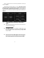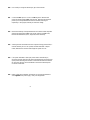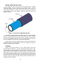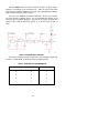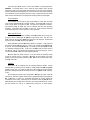
1
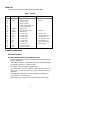
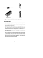
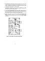
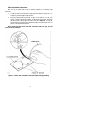
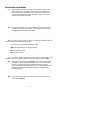
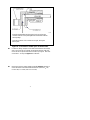
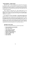
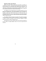
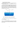
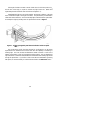
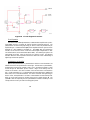
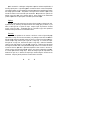
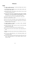
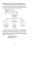
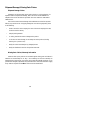
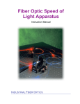
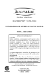
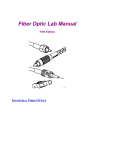
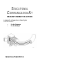
EDUCATIONAL
COMMUNICATION KIT
RADIANT ENERGY IN ACTION
A Hands-On Introduction to Fiber Optics
Communications
•
•
For the Classroom
For the Hobbyist
INDUSTRIAL F IBER OPTICS
*
Copyright © 2000
Industrial Fiber Optics, Inc.
*
*
*
All rights reserved. No part of this publication may be reproduced, stored
in a retrieval system, or transmitted in any form or by any means without
express written permission from Industrial Fiber Optics.
*
*
*
INDUSTRIAL F IBER OPTICS
627 South 48th Street, Suite 100
Tempe, AZ 85281
*
*
Table of Contents
Preface ....................................................................................
ii
OBJECTIVE ............................................................................
1
STARTING OUT ....................................................................
1
TOOLS AND TEST EQUIPMENT YOU'LL
NEED ......................................................................................
1
PARTS LIST ............................................................................
2
ASSEMBLY INSTRUCTIONS ...............................................
2
EXPERIMENTS AND ACTIVITIES......................................
6
"NUTS AND BOLTS" OF FIBER OPTICS ..........................
10
GLOSSARY .............................................................................
20
REFERENCES ........................................................................
22
ADDITIONAL PRODUCTS ..................................................
24
SHIPPING DAMAGE/MISSING PARTS CLAIMS.............
26
*
*
ii
*
Preface
Fiber optics technology is rapidly becoming a familiar and indispensable part of
American life.
Long-distance telephone companies can't say enough good things about the bold new
technology that has revolutionized communications systems across the county and, not far
in the future, will span the globe. Futurists, science writers and entrepreneurs forecast
fantastic growth for fiber optics applications.
And their enthusiasm is valid. Today, medical fiber optic systems allow physicians to
peer inside the human body without surgery. Military commanders demand portable
battlefield communications systems which use superior fiber optic transmissions. The
massive bundles of copper wiring which once carried telephone conversations between
continents, beneath the oceans, now are being replaced with much smaller optical fibers.
Fiber optic amplifiers with higher bandwidth and greater reliability are replacing electronic
repeater stations.
The next decade promises even more wonders. The influence of fiber optics will
pervade our homes, workplaces and recreational facilities. Your television reception will
take on startling clarity and increased resolution. Newsprint may largely become a thing
of the past as environmentally friendly and custom "electronic newspapers" become
feasible. Two-way fiber optic systems will allow you to "attend college" in the comfort of
your home as well as enjoying faster download times when using the Internet.
Anyone who takes an interest in fiber optics and pursues a career in the field today is
on the ground floor of opportunity. The technology is sufficiently new that few "experts"
exist. Increasing numbers of classes in fiber optics are being offered at the high school and
university levels. The future beckons enticingly with the prospect of making new
discoveries, finding new applications for the technology.
This kit is an introduction to fiber optics communications for the instructor, student
and hobbyist. We hope that you find the materials challenging, stimulating and—yes—
even fun.
ii
Objective
The purpose of this kit is to provide you hands-on experience with constructing basic
fiber optic receivers, transmitters and cable interfaces, not unlike those used by telephone
companies. This booklet contains a parts list; complete assembly instructions; some
technical discussions about why everything here works as it does; and a glossary of terms
used. You will learn how and why light can be "captured" and transmitted by lengths of
optical fiber. With the basic information you gain, you can go on to more sophisticated
discussions and demonstrations of fiber optics in action.
Starting Out
In preparing this manual, we assumed you have a basic grasp of digital and transistor
circuits. If these topics aren't your strong points, you may choose to skip some of the
theory and exercises. You'll still be able to construct the kit and learn the most important
fundamentals of fiber optics. Consult the Glossary in the rear of the manual if you're
uncertain about the meanings of technical terms.
When you have completed this kit and demonstrations, we hope you'll want to move
up to more advanced material. See page 24 in this manual for a list of other exciting fiber
optics products available to you.
Portions of this kit call for the use of an oscilloscope to perform demonstrations and
to make some of the measurements. If you don't have, or want to use an oscilloscope,
you can make two changes which will still permit you to conduct the demonstrations.
First, solder a 10 µf axial-leaded electrolytic capacitor to the transmitter printed wiring
board, at the location marked "optional". Second , so lder an LED acros s the outp ut p ins on
t he recei ver marked "Dat a" and "Dat a Bar" (po larity is not i mport ant) . During operat ion,
t he LED wil l bli nk on an d off with the trans mitter circu it. The visual blinking of the LED is
comparable to the waveform as would be seen on an oscilloscope.
Tools and Test Equipment You'll Need
Wire cutters
Needle-nose pliers
Small Phillips screwdriver
Small adjustable wrench
1 ml water or light oil
Rosin-core solder
Single-edge razor blade or sharp knife
25-watt soldering iron
18-gauge wire-stripper
5-volt DC power supply
Dual-trace oscilloscope
Four electrical clip-leads
1
Parts List
Your kit should contain all the components listed in the table below.
Table 1. Parts list.
P/N
C1
D1
H1
H2
F1
H3
Q1
Q2
Q3
R1
R2
R3
R4
R5
R6
R7
U1
U2
Description
Color-code
Mylar ® capacitor
IF-E96
2N3904
IF-D92
2N3904
220 K
33 K
3.9 K
33 K
100 Ω
33 K
1K
4093
4093
.01 µf
Fiber optic red LED
Two 2/56 screws
Two 2/56 hex nuts
1-meter 1000 µm plastic fiber
600 grit polishing paper
NPN transistor
Fiber optic phototransistor
NPN transistor
1/4 watt resistor
1/4 watt resistor
1/4 watt resistor
1/4 watt resistor
1/4 watt resistor
1/4 watt resistor
1/4 watt resistor
Quad CMOS Schmitt
Quad CMOS Schmitt
Pink Dot
White Dot
Red Red Yellow
Orange Orange Orange
Orange White Red
Orange Orange Orange
Brown Black Brown
Orange Orange Orange
Brown Black Red
Assembly Instructions
Printed Wiring Board
Follow the guidelines below when assembling your kit:
•
Mount all components on the side of the printed wiring board with the white
lettering. (Solder Side.)
•
Use the white markings on the printed circuit board to determine the location
and orientation of each part. (Component Side.)
•
All soldering is to be completed on the opposite side.
•
Use a water soluble or rosin core solder such as Radio Shack P/N 64-001. Do
not use an acid or caustic flux solder such as used in industrial or plumbing
applications.
•
Avoid applying prolonged heat to any part of the board or component, to
prevent damage. 5 Seconds maximum.
•
After soldering each component, trim its lead length flush with the solder.
2
Resistor
Capacitor
1
Integrated Circuit
Transistor
Figure 1. Component identification: resistors, capacitors, ICs.
Board Assembly Steps
1.
Insert resistors R1 through R7, one at a time, into the printed wiring board and
solder them in place.
2.
There is no positive/negative orientation of capacitor C1. Identify, insert leads
through the board and solder in place.
3.
Identify pin 1 of U1 and U2 (the lower left pin of the integrated circuit [IC],
when viewed from above). Insert the ICs into designed spots marked on the
printed circuit board, with pin 1 to your lower left. The lettering on the ICs
will face the same direction as the markings on the board. Solder in place.
4.
Identify Q1 and align the package design with the detail on the printed wiring
board. Insert and solder.
5.
Clean the printed circuit board with soap and warm water to remove solder
residue. Soapy water will not harm the components as long as electrical power
is not being applied–in which case you don't want to get anywhere near water
anyway, for safety's sake. If you used a rosin core solder, clean the board with
the denatured alcohol before washing in soap and water. Rinse thoroughly.
Shake the board to remove water from under the ICs. Wipe everything dry
with paper towels and let air-dry for 30 minutes.
3
6.
Identify D1 as the blue fiber optic housing with the pink dot on one side. (The
printed wiring board may have the part number IF-E91A marked on it instead of
IF-E96.) Insert D1 in the designated area on the printed wiring board. Fasten
in place with 2/56 screw and nut. Solder the leads.
7.
Identify Q2 as the black fiber optic housing with the white dot on one side.
Insert Q2 in the designated area on the printed wiring board. Fasten in place
with 2/56 screw and nut. Solder the leads.
8.
If you are going to operate this kit from one power supply, solder jumper wires
from solder pads GND to GND, and +5V to +5V on the center left portion of
the printed wiring board. If you want to use separate transmitter and receiver
power supplies, break the two boards apart at the scribed junction.
9.
Solder 24-gauge wires to the connections labeled +5V, GND, EN, EXT,
DATA on the edge of each board. (If you have chosen to keep the boards
together you will need to attach wires to only one of the two +5V and GND
connections.)
Figure 2. Board details on the printed wiring boards.
4
Fiber Preparation Instructions
Each end of the optical fiber must be carefully prepared so it transmits light
effectively.
1.
Cut off the ends of the cable with a single-edge razor blade or sharp knife. Try
to obtain a precise 90-degree angle (square).
2.
Wet the polishing paper with water or light oil and place it on a flat, firm
surface. Hold the optical fiber upright, at right angles to the paper, and polish
the fiber tip with a gentle "figure-8" motion as shown in Figure 3. You may get
the best results by supporting the upright fiber against some flat object such as a
portion of the printed wiring board.
(Don't insert the fiber ends into their connectors until we give you the
word, in the next section.)
Figure 3. Pattern and orientation of the optical fiber during polishing.
5
Experiments and Activities
A1.
Grasp the optical fiber near its tip with your thumb and forefinger. Point it
toward a light source and different colored objects, while observing the
other end of the fiber. Note the changes in brightness in that end as you
move the other end around, or cover its tip with a finger. Do any colors
seem to transmit better than others?
A2.
Holding the fiber about .5 mm (.020 inches)from this page, move it left to
right across the heading of this section. What changes do you observe in
the brightness at the other end of the fiber?
With your power supply turned off, make the following connections with the
electrical clip leads to the printed wiring board(s).
•
+5 volts to the positive terminal on the power supply
•
GND to the negative terminal on the power supply
•
EN to the negative terminal
•
EXT to positive terminal
If you are using a variable voltage power supply, turn the voltage down to the
minimum. Then turn the power supply on, and adjust the power supply to 5 volts.
A3.
Determine if the Transmitter LED (IF-E96) is on by measuring the voltage
across R5. It should measure approximately 3 volts. If the LED does not
have any current flowing through it, double-check the power supply,
electrical connections, and assembly sequence. (You will be able to see the
light being emitted from the LED if you through the hole that the fiber
would be inserted.)
A4.
Insert one end of the optical fiber into the fiber optic LED, following the
instructions in Figure 4.
6
Insert the prepared fiber end through the cinch nut and into the
connector until the core tip seats against the molded lens inside the
device package.
Screw the connector cinch nut down to a snug fit, locking the
fiber in place.
Figure 4. Cross-section of fiber optic LED and cable.
A5.
In electronic design, multiple circuits often will achieve the same design
goals. We'd now like you to design an alternative electronic LED drive
circuit that will accept an external and oscillator input signal. Draw that
circuit below. You may use Figure 9 as a reference.
A6.
What is the minimum output voltage at Gate d in Figure 9 necessary to
ensure saturation of the LED drive NPN transistor? (Assume hfe= 50;
Vce=0.2 volts; Vcc=5 volts; and V LED=1.5 volts.)
7
Insert the unattached fiber end into the fiber optic phototransistor, following the
same steps in Figure 4.
Connect the EXT and the EN inputs to +5 volts. Turn power on to the
oscilloscope and set the horizontal time scale to .2 milliseconds per division and
the vertical scales to 2 volts/division for both channels. Hook up one probe of a
dual-trace oscilloscope to TP1 on the transmitter circuit and the other to TP3 on the
receiver circuit. (You should see two square wave signals similar to those shown in
Figure 5a.)
Figure 5. Two oscilloscope traces of: a) transmitter TP1 (top) and receiver TP3
(bottom) signals; and b) receiver TP3 (top) and TP2 (bottom)
signals.
A7.
Measure the transmitter board's oscillator period with the oscilloscope and
calculate the oscillating frequency.
Hz
A8.
Move Probe 1 located on the transmitter to TP2 (emitter of the
phototransistor Q2) and observe the received signal as depicted in Figure
5b. Is the frequency the same? What does the signal at TP2 look like
compared to TP3?
A9.
Measure the rise and fall time at TP2. Estimate or determine the maximum
data rate this data link could transmit. (Hint: The answer can be empirically
determined using an external function generator connected to the EXT
input, or analytically determined, from the measured rise and fall times.)
8
A10. How would you change the sensitivity or gain of this receiver?
A11. Connect the EXT input to + 5 volts and EN to ground. Measure and
record the emitter voltage at Q2 of the receiver. Determine the minimum
power input to the phototransistor base from the fiber (assuming its
responsivity is 125 µA/µW) necessary to create this voltage.
A12. What is the sensitivity of the phototransistor and common-emitter amplifier?
(Assume the responsivity of Q2 is 125 µA/µW, and the hfe of Q3 is 50.)
What are the dimensions (ft/sec, amps/volt) of this sensitivity?
A13. Assuming that this transmitter launches 15 µwatts of energy into the fiber, a
receiver sensitivity of 1.25 x 10⁻¹ µwatts, and fiber attenuation 1 dB per
meter, determine the maximum cable length this system can use.
A14. If an optical radiometer or fiber optic power meter is available to you,
disconnect the optic fiber from the receiver phototransistor and measure the
optical power emanating from the fiber. Recalculate the maximum distance
for which this data link can be used based on the actual measured power
out of the 1-meter fiber.
A15. Design a fiber optic transmitter and receiver circuit using PNP transistors
and a negative 5-volt power supply. Draw your design below.
9
"Nuts and Bolts" of Fiber Optics
Before fiber optics came along, the primary means of real-time data communication
was electrical in nature. It was accomplished using copper wire or by transmitting
electromagnetic (radio) waves through free space. Fiber optics changed that by providing
an alternate means of sending information over significant distances–using light energy.
Although initially a very controversial technology, fiber optics has today been shown to be
very reliable and cost-effective.
Light, as utilized for communications, has a major advantage because it can be
manipulated (modulated) at significantly higher frequencies than electrical signals. For
example, a fiber optic cable can carry up to 100 million times more information than a
telephone line! The fiber optic cable has lower energy loss and wider bandwidth
capabilities than copper wire.
As you will learn, fiber optic communication is a quite simple technology, closely
related to electronics. In fact, it was research in electronics that established the
groundwork for fiber optics to develop into the communications giant that it is today.
Fiber optics became reality when several technologies came together at once. It was not
an immediate process, nor was it easy, but it was most impressive when it occurred. An
example of one critical product which emerged from that technological merger was the
semiconductor LED, of the type used in the educational kit which you have constructed.
The following sections provide more detail about the electronics nature of a basic fiber
optic data link, and the theory of operation for your Industrial Fiber Optics kit.
Advantages of Fiber Optics
Fiber optics has at least eight advantages over conventional copper cables:
•
Greater information-carrying capabilities
•
Smaller cable diameter
•
Lighter weight-per-cable length
•
Greater transmission distance
•
Immunity to electrical interference
•
Cables do not radiate energy
•
Greater reliability
•
Lower overall cost
10
Elements of a Fiber Optic Data Link
Basically, a fiber optic data link contains three main elements: a transmitter, an
optical fiber, and a receiver. The transmitter takes data previously converted to electrical
form and transforms it into optical (light) energy containing the same information. The
optical fiber is the medium which carries the energy to the destination (receiver). At the
receiver, light is converted back into electrical form with the same pattern as originally fed
to the transmitter by the person who wanted to send the message.
It is important to note that optical energy can be beamed through the air or free
space (like a flashlight beam). In fact, there are applications in which communication
through air is used when installing optical fiber would be too costly or impractical. The
advantage of optical fiber is that it allows light to be routed around corners and
transported through obstructions (such as walls in buildings), just as household electrical
and telephone wiring do, but with much greater signal-carrying capacity plus being able to
operate on foggy and rainy days.
Also contained in fiber optic data links are connectors that provide the connections
between transmitter and receiver modules and optical fiber. These allow quick addition
or removal of modules, and the ability to offer communication capabilities at multiple
locations using various "coupling" and "splitting" devices.
The educational kit you have constructed contains all the elements described above
with the exception of multiple distribution devices, since it links a single receiver and
transmitter.
11
Why Optical Fiber Works As It Does
The behavior of light which you saw demonstrated in the preceding activities has a
precise scientific explanation. (Remember to consult the Glossary in this manual if the
meaning of a term isn't clear to you.)
Light travels in straight lines through most optical materials, but that's not necessarily
the case at the junction (interface) of two materials with different refractive indices. Air
and water are a case in point, as shown in Figure 6. The light ray traveling through air
actually is bent as it enters the water. The amount of bending depends on the refractive
indices of the two materials involved, and also on the angle of the incoming (incident) ray
of light as it strikes the interface. The angle of the incident ray is measured from a line
drawn perpendicular to the surface. The same is true for the angle of the outgoing
(transmitted) ray of light after it has been bent.
Figure 6. Different portions of a light ray at a material interface.
The mathematical relationship between the incident ray and the refracted ray is
explained by Snell's Law:
n1 • sin Θ1 = n 2 • sinΘ2
in which n1 and n 2 are the refractive indices of the initial and secondary materials,
respectively, and Θ 1 and Θ 2 are the incident and transmitted angles. If n1 is larger than
n 2 , Snell's Law says that refraction (bending) of light cannot take place when the angle of
incidence is too large.
12
If the angle of incidence exceeds a certain critical value (in which the product of n1
and the sine of the angle, Θ, equals or exceeds one) light cannot exit. (Recall from
trigonometry that the maximum value of the sine of 90 degrees is 1.)
If mathematically light can not exit the material, 100 percent is reflected. The angle
that it is reflected is equal to the angle of incidence. The phenomenon just described is
called total internal reflection, and it is what keeps light contained inside an optical fiber.
An example of a light ray traveling down an optical strand is shown in Figure 7.
Figure 7. A light ray trapped by total internal reflection inside an optical
fiber.
The concept above, which has been discussed in one dimension, can be further
expanded into two dimensions which would then have the capability of channeling or
directing light. The most common two-dimensional model to achieve is a solid rod of
material surrounded by a layer of lower-refractive-index material. This two dimensional
light confinement construction demonstrates the fundamental mode whereby light travels
through all optical fibers. If you'd like to learn more about the mathematics governing
fiber optics, we recommend that you consult the books listed in the References section.
13
About the Optical Fiber We're Using
The simplest fiber optic cable consists of two concentric layers of optically
transparent materials. The inner portion (the core) transports the light. The outer
covering (the cladding) must have a lower refractive index than the core, so the two are
made of different materials. The cable used in this kit also has a jacket to protect the
optical properties of the core and cladding. Cables can contain more layers if the
application requires it.
Figure 8. Cross-section of a simple fiber optic cable.
Optical fiber is generally made from either plastic or glass. This kit uses plastic fiber,
which is very easy to terminate and does not require special tools. Plastic is generally
limited to uses involving distances of less than 150 meters. Glass fiber, on the other hand,
has very, very low attenuation (light loss), is hard to cut, requires special end connections
and is more expensive, but can be used in very long distance applications.
The plastic fiber in this kit has a polyethylene jacket, a fluorine polymer cladding and
a polymethyl methacrylate polymer (PMMA) core. The core is 980 µm (0.04 inches) in
diameter, surrounded by 10 µm of cladding.
Transmitter
Systems which send data, whether it is voice or digital information, almost never
power the optical sources directly. This role is handled by transmitter electronics. Fiber
optic transmitters are typically composed of a buffer, driver and optical source. Often,
optical connectors are also integrated into the final package. The buffer electronics
provide both an electrical connection and "isolation" between the driver/optical source
and the electrical system supplying the data. The driver electronics provide electrical
power to the optical source in a fashion that duplicates the pattern of data being fed to the
transmitter. Finally, the optical source (LED in this kit) converts the electrical current to
light energy with the same pattern.
14
The LED, IF-E96, supplied with this kit produces red light. Its optical output is
centered at a wavelength of 660 nanometers (nm). LEDs are useful for fiber optics
because they are inexpensive, reliable, easy to operate, have a wide temperature operating
range, and respond quickly to electrical current.
The kit you have assembled has additional electronics in the form of an oscillator.
This circuit provides a repetitive signal so you can demonstrate the operation of the
transmitter without additional equipment. Note that the kit handles only digital data,
produced with an electrical signal which is either On or Off (also known as "high" or
"low").
Figure 9. Transmitter board schematic.
The following discussion assumes the reader has a basic knowledge of digital logic
functions (e.g., AND, NAND, OR, NOR) and theory of transistor operation.
Table 2. Truth table for 2-input NAND Gate.
Input 1
Input 2
Output
0
0
1
0
1
1
1
0
1
1
1
0
15
The Quad 2-input NAND CMOS IC used in the transmitter is a special type called a
SCHMITT. The Schmitt device is one in which the input voltage at which the gate
switches from logic low to high is higher than that which would cause a logic high-to-low
transition (different threshold depending on which direction the input signal is traveling).
This characteristic improves the gate's immunity to noise on signals with slow rise and fall
times (as will be discussed later), and sharpens the resulting output from these signals.
Circuit Operation
The transmitter uses two gates of quad 2-input NAND IC (c and d) for the buffer
circuit, and two gates (a and b) as a relaxation oscillator. The transistor (Q1) is used as a
driver to switch power on and off to the LED. The entire circuit operates at a nominal 5
volts–standard voltage for digital logic used in computers and other data processing
equipment. Logical highs and lows (digital "1"s and "O"s), can be created by electrically
connecting that input to +5 volts or ground (O volts), respectively.
Buffer and LED Driver
Assume the on-board oscillator is disabled, and the EN (enable) input is at logic low,
forcing the output of NAND gate "d" (pin 11) to logic high (5 volts). Gate "b" in the
buffer circuit now has one input ( pin 5) above logic high so its output will be determined
by the logic level at the EXT (External) input (pin 6).
When digital data is fed to the EXT input, operation is as follows: A logic high forces
the output of gate "b" (pin 6) to logic low. Gate "c" now has both inputs (pins 8 and 9)
at logic low, forcing its output (pin 10) high. The resulting current through R3 turns Q1
on, completely energizing the LED. A logic low at the EXT input forces the output of
gate "b" high. Gate "c" now has both inputs at logic high, forcing its output low. There is
no current through R3, so Q1 turns off, de-energizing the LED.
R3 limits Q1's base emitter current to a safe level while still providing enough
current for complete turn-on or saturation. R4 bleeds off stored charges in the baseemitter junction, allowing faster operation for Q1. R5 sets the maximum LED current
when Q1 is saturated.
Oscillator
Gates " a" and "d" are configured as an RC-controlled relaxation oscillator. Assume
the transmitter is powered up and the oscillator is initially disabled (the EN input [pins 2
and 13] is at logic low). The outputs of gates "a" and "b" will both be high, and capacitor
C1 will be uncharged because the net voltage across it is zero (pins 3 and 11 are both at
5 volts).
Upon enabling the oscillator (logic high applied to EN input) the output of gate "d"
switches low, while that of gate "a" remains high as capacitor C1 begins charging through
R2. If EN input is a logical one, the NAND gates behave as inverters (outputs are
complements of the inputs), responding only to conditions present on pins 12 and 1.
Remember that the net voltage across a capacitor cannot change instantaneously, so when
gate "d" switches low, node "j" is instantaneously brought low to satisfy capacitor
16
operation. Pin 1 of gate "a" senses the same input combination present prior to enabling
the oscillator, causing its output to remain high.
As C1 charges, the voltage at node "j" increases to a level recognized as a logic high
by gate "a", causing its output to switch low. Gate "d" now switches from low to high,
and capacitor C1 begins charging in the opposite direction or polarity. The voltage at
node "j" starts decreasing until a level recognized as logic low by gate "a" is reached. The
output of gate "a" goes high, input to gate "d" goes low and the cycle repeats.
The transmitter and oscillator have four possible operational modes resulting from
logic levels present on the EN and EXT inputs. These are summarized in Table 3.
Table 3. Transmitter oscillator truth table.
Mode
EN
EXT
LED State
1
0
1
ON
2
0
0
OFF
3
1
1
OSCILLATING
4
1
0
OFF
Receiver
Once light energy from the fiber optic transmitter reaches the destination (receiver) it
must be converted back to a form of electrical energy with the same information pattern
that was fed to the transmitter by the person sending the message. Fiber optic receivers
typically perform this function using three elements: a photodetector, an amplifier and a
digitizer. As with fiber optic transmitters, the optical connector is often integrated into the
total package as is the case in this kit. The photodetector converts light energy (optical
power) to an electrical current. Any pattern or modulation imparted in the optical power
(from, for instance, a fiber optic transmitter) will be reproduced as an electric current with
the same pattern. Long lengths of fibers and other distribution losses can reduce the
optical power, resulting in a comparatively small electrical current from the photodetector.
To compensate for this decline in signal strength the amplifier increases the amplitude of
the electrical signal. Finally, a digitizer converts the amplified signal to digital levels and
provides the correct voltage levels for the external logic.
17
Figure 10. Circuit diagram of receiver.
Circuit Operation
The receiver uses an NPN phototransistor, an NPN transistor amplifier and a quad 2input NAND CMOS IC to perform all electrical functions mentioned previously. The
phototransistor converts incoming light energy to electric current, and provides some preamplification gain. The NPN transistor (Q3) further amplifies the electric signal to raise its
amplitude to a level suitable for the NAND IC. The NAND gates are configured as
inverters, two of which are used to convert the received signal to digital levels, in both
non-inverted (DATA) and inverted formats (DATA BAR). The remaining two gates in the
quad package are unused. Power for the circuit is a nominal +5 volts. The following
discussion about the receiver operation assumes the reader has a basic understanding of
digital logic and transistor operation.
Photodetector and Amplifier
Q2 is an NPN phototransistor. A phototransistor is similar to a normal transistor, but
different in that it has an exposed base to receive light. This base acts as a photodetector,
generating base current when exposed to light. Like a conventional transistor, a small
current through the base-emitter junction controls a larger current flowing from the
collector to the emitter. (The ratio of collector current to base current is the transistor's
gain – usually expressed as hfe.) In a phototransistor the same phenomenon amplifies the
base current, as in a conventional transistor. The result is conversion from light energy to
electric current, and amplification in one device. Phototransistors are often rated by their
ability to convert optical energy to electrical energy with a transfer function R. The
symbol R is short for responsivity, and for a phototransistor indicates its sensitivity in units
of amps (collector current ) per watt of incoming optical power.
18
Q3 is connected in a darlington configuration to Q2 for maximum amplification of
incoming optical power. Light striking Q2 is converted to electric current and amplified.
The resulting emitter current is applied into the base of Q3, further amplified and controls
the voltage signal across R7. The pattern of the signal at the collector of Q3 will be
inverted in relation to that of the fiber optic transmitter. R6 provides a DC path for the
leakage current from Q2, and a discharge path for stored charges in the base-emitter
junction of Q3 when no optical power is incident upon the base of Q2.
Digitizer
Gate "e" converts the analog signal across the collector of Q3 to a digital logic level.
It performs this by switching its output whenever the voltage goes just above, or just
below, a valid logic low or high at the input. Output of gate "f" provides an inverted
version of the input data. The NAND gates are a SCHMITT type, with operational
benefits previously discussed in the Transmitter section.
Summary
Typical flow of operation for the receiver is as follows: With no light striking Q2
(equivalent to a logic low from the transmitter), only leakage current flows into R6 and
the base of Q3, leaving it essentially turned off. Since no current flows through R7, the
collector of Q3 is high, and the input to gate "e" is a logic high. As a result, the output
from gate "e" is a logic low, and that from gate "f" a logic high. When the transmitter
output is a logic high (digital "1"), the LED (D1) is turned on. Light from the LED travels
the length of the fiber cable to the phototransistor Q2, where it is converted to electric
current and fed into Q3's base. Q3 further amplifies its base current in the form of
collector current, which flows through R7, which in turn causes a voltage drop across R7.
As a result, Q3's collector voltage drops. When the voltage to gate "e" drops below the
threshold for logic low, it switches its output high, reconstructing the condition at the
transmitter. Output of gate "f" provides an inverted version of the data.
#
#
#
19
GLOSSARY
Absorption. In an optical fiber, the loss of optical power resulting from conversion of
that power into heat. See also: Scattering
Acceptance Angle. The angle within which a fiber will accept light for transmission
along its core. This angle is measured from the centerline of the core.
Analog. A type of information system in which the information is constantly varying.
Sound is analog because it varies within a given frequency range. Compare with: Digital.
Attenuation. Loss of optical power (i.e., light pulses losing some of their photons),
normally measured in decibels per kilometer.
Cable. A single optical fiber or a bundle of fibers, often including strengthening strands of
opaque material and a protective outer jacket.
Cladding. The layer of glass or other transparent material surrounding the light-carrying
core of an optical fiber that keeps the light trapped in the core. It has a lower refractive
index than the core. Additional coatings, such as jackets, are often applied over the
cladding to strengthen and protect it.
Core. The central, light-carrying portion of an optical fiber.
Connector. A device which joins two fiber optic cable ends or one fiber end and a light
source or detector.
Coupler. A device which connects three or more fiber ends, dividing one input between
two or more outputs, or combining two or more inputs in one output.
Critical Angle. The incident angle at which light undergoes total internal reflection in a
fiber.
Darlington. An electronic circuit in which the emitter of one transistor is fed into the
base of another transistor to amplify current.
Detector. A device that generates an electrical signal when illuminated by light. The
most common in fiber optics are photodiodes, photodarlingtons and phototransistors.
Digital. A type of information system in which the information exists in the form of
precise numerical values of digital pulses. The fundamental unit of digital information is
the bit–short for binary digit. Compare with: Analog.
Diode. An electronic device which usually restricts electric current flow to one direction.
Fiber. The optical waveguide, or light-carrying core or conductor. It may be made of
glass or plastic. See also: Core; Cladding.
IC. Integrated circuit. A tiny slice or "chip" of material on which a complete electrical
circuit has been etched or imprinted.
Incident ray. An "incoming" ray of light–light which falls upon or strikes a surface.
Compare with: Reflected ray.
Infrared. Electromagnetic energy with wavelengths longer than 750 nanometers and
shorter than 1 millimeter. Infrared radiation cannot be seen, but it can be felt as heat or
measured.
Jacket. A layer of material surrounding an optical fiber to protect the optical core and
cladding but not bonded to it.
LED. Light-emitting diode. A semiconductor diode which converts electrical energy to
light.
20
Light. Strictly speaking, electromagnetic radiation visible to the human eye. Commonly,
however, the term is applied to electromagnetic radiation with properties similar to those
of visible light, including the invisible near-infrared radiation used in fiber optic systems.
See also: Infrared.
Near-Infrared. Wavelengths of radiation longer than 700 nm and shorter than 1 mm.
Infrared radiation cannot be seen but can be felt as heat. Glass fibers transmit radiation
best in the region 800 – 1600 nm, and plastic fibers in the 640 nm to 900 nm range.
Numerical Aperture. (NA) The sine of the angle over which an optical fiber can accept
light. Incident light which strikes the end of an optical fiber can be transmitted along that
fiber only if the light strikes the fiber within the numerical index. If the incident light
strikes the end of the fiber at too oblique an angle, it won't travel down the core of the
fiber.
Photodetector. A device which detects and receives light waves (optical energy), then
converts them into electrical signals.
Photons. Units of electromagnetic radiation. Light can be explained as either a wave or
a series of photons.
Phototransistor. A transistor that detects light and amplifies the resulting electrical
signal. Light falling on the base-emitter junction generates a current, which is amplified
internally.
Reflected ray. A ray of light which has "bounced off" some surface. When an incident
ray strikes a surface and bounces off, it becomes a reflected ray.
Refracted ray. A light ray which has been bent by its passage from one medium into
another medium of different refractive index.
Refractive index. The ratio of the speed of light in a vacuum to the speed of light in a
material; abbreviated "n".
Receiver. A device that detects an optical signal and converts it into an electrical form
usable by other devices. See also: Transmitter.
Responsivity. The ratio of detector output to input, usually specified in Amperes/watt
for photodiodes, photodarlingtons and phototransistors.
Scattering. The changes in direction of light travel in an optical fiber occurring due to
imperfections in the core and cladding material.
Splice. A permanent junction between two optical fiber ends.
Step-index fiber. An optical fiber in which the refractive index changes abruptly at the
boundary between core and cladding.
Transmitter. A device that converts an electrical signal into an optical signal for
transmission in a fiber cable. See also: Receiver.
21
References
Books
Fiber Optics: A Bright New Way to Communicate, Billings, Dodd, Mead &
Company, New York, NY 1986
The Rewiring of America: The Fiber Revolution, David Chaffee, Academic Press,
Inc., Orlando FL 32887, 1988
Understanding Fiber Optics, Second Edition, Hecht, Howard W. Sams, 201 West
103rd Street, Indianapolis, IN 1993
Technician's Guide to Fiber Optics, Second Edition, Sterling, AMP Incorporated,
Harrisburg, PA 17105, 1993 (Paperback), Delmar Publishers, 2 Computer
Drive West, Box 15-015, Albany, NY 12212-9985 (Hardbound Edition)
An Introduction to Optical Fibers, Cherin, McGraw-Hill Book Company, 1983
Fiber Optics, Lacy, Prentice-Hall, Inc., 1982
Fiber Optic Communications, Foruth Edition, Palais, Prentice-Hall Publishing, 1991
Fiber Optics and Laser Handbook, Second Edition, Safford and McCann, Tab Books,
BlueRidge Summitt, PA 17294, 1988
Fiber Optics Handbook for Engineers and Scientists, Allard, McGraw-Hill
Publishing, New York, NY, 1990
Optical Fiber Transmission, Basch, Howard W. Sams, 201 West 103rd Street,
Indianapolis, IN 46290, 1986
Principles of Optical Fiber Measurements, Marcuse, Academic Press, 1974
Semiconductor Devices for Optical Communications, Kressel, Springer-Verlag, Inc.,
1980
Safety with Lasers and Other Optical Sources, Stiney and Wolbarsht, Plenum Press,
1980
Safe Use of Lasers, ANSI Standard Z136.1, LIA, 12424 Research Parkway, Suite
130, Orlando, FL 32826
Safe Use of Optical Fiber Communications Systems Utilizing Laser Diodes & LED
Sources, ANSI Standard Z136.2, LIA, 12424 Research Parkway, Suite 130,
Orlando, FL 32826
22
Periodical publications
Applied Optics, Optical Society of America, 1816 Jefferson Place, NW, Washington,
DC 20036
Fiberoptic Product News, Gordon Publications, Inc., Box 1952, Dover, NJ 07801
Laser Focus World, PenWell Publishing Co., 1421 S. Sheridan, Tulsa, OK 74112
Lightwave Magazine, PenWell Publishing Co., 1421 S. Sheridan, Tulsa, OK 74112
Optical Engineering, SPIE, P. O. Box 10, Bellingham, WA 98227-0010
Photonics Spectra, The Optical Publishing Co., Berkshire Common, Pittsfield, MA
01202-4949
Fiber Optic Buyers Guide
Fiberoptic Product News Buying Guide, Gordon Publications, Inc., Box 1952,
Dover, NJ 07801
Lightwave 2000 Buyer's Guide, PenWell Publishing Co., 1421 S. Sheridan, Tulsa,
OK 74112
Organizations
Optical Society of America, 1816 Jefferson Place, NW., Washington, DC 20036
Society of Photo-Optical Instrumentation Engineers (SPIE), P. O. Box 10,
Bellingham, WA 98227-0010
Laser Institute of America, 12424 Research Parkway, Suite 130, Orlando, FL 32826
23
Additional Products for Classroom, Hobbyist and Scientist
Industrial Fiber Optics manufactures a wide variety of top-quality products suited for
all users, from the student and casual experimenter to professional researcher. All of
Industrial Fiber Optics' products are based on light–its application and understanding
(light is defined as the electromagnetic spectrum where invisible radiation has the
properties of "visible" light). Our educational products portfolio includes:
lasers which produce light,
optics which reflect or refract light,
fiber optics which produce and transmit light.
These educational products fall into three main categories:
We make every effort to incorporate state-of-the-art technology, highest quality, and
dependability in our products. We constantly explore new ideas and products to best
serve the rapidly expanding needs of industry and education. We encourage comments
that you may have about our products, and we welcome the opportunity to discuss new
ideas that may better serve your needs. If you would like a catalog on any of the products
above, please contact us by phone or fax at (480) 804-1227 and (480) 804-1229,
respectively. You may contact us in writing at:
INDUSTRIAL FIBER O PTICS
627 South 48th Street, Suite 100
Tempe, AZ 85281
24
More kits:
OPTICAL VOICE L INK
The Optical Voice Link is a kit which when assembled converts your voice to a light
signal, couples this light through an optical fiber, and then converts it back to an audio
tone. This kit is a favorite and may have earned more high grades and scholastic honors
for student science projects than any other. For students and experimenters alike, the
Optical Voice Link is the ideal demonstrator of the marvels, mysteries, and science of light
transmission through optical fiber. (Product number IF-OVL10-K)
ADVENTURES IN FIBER OPTICS
This is a fun-filled product with 20 exciting experiments and 5 interesting projects to
amaze your friends including "Bending a Light Guide", "Fluorescence", Tyndall's
Prestigious Experiment", "Image Magnification", and making a fiber optic wand and
lighted constellation map. In addition to materials necessary to complete all the
experiments the step-by-step instruction guide contains lots of scientific facts and trivia.
(Product number IF-E60)
SPEED OF LIGHT KIT
For centuries men and women of science tried in fascinating ways to measure the
speed of light. The culmination of their efforts is this low-cost ingenious kit that once
assembled allows the common person to measure the speed of light. Included with the
electronic and physical components is an easily understood and often lighthearted manual
which traces the steps of the pioneers in optics research as well as step-by-step assembly
instructions. (Product number IF-SL-K)
LAB KIT
A kit that contains a 68-page technical manual, and all the fiber optic and electronic
components needed to complete nine exciting experiments in fiber optics. Experiments
include "Making a Light Guide," "Fiber Optic Cable Transmission," "Connectors and
Splices," "Index Matching," "Fiber Terminations," and "Fiber Optic Receivers." Manual
also contains a list of references and glossary of fiber optic terms. (Product number IFLMH)
PLASTIC FIBER TOOL K IT
Contains a fiber stripper, hot-knife cutting tool, universal fiber cutter, fluid dispenser,
glass polishing plate, polishing film, ST polishing puck, replacement cutting blade and
convenient carrying case. With the tools in this kit you will be able to cut, polish nearly
all jacketed and unjacketed single strand optical fibers as well as multi-fiber bundles in
addition to terminate fibers into standard ST receptacles. (Product number IF-TK4)
25
Shipment Damage/Missing Parts Claims
Shipment Damage Claims
If damage to an Industrial Fiber Optics product should occur during shipping, it is
imperative that it be reported immediately, both to the carrier and the distributor or
salesperson from whom the item was purchased. DO NOT CONTACT INDUSTRIAL
FIBER OPTICS.
Time is of the essence because damage claims submitted more than five days after
delivery may not be honored. If shipping damage has occurred during shipment, please
do the following:
•
Make a note of the carrier company; the name of the carrier employee; the date;
and the time of the delivery.
•
Keep all packing material.
•
In writing, describe the nature of damage to the product.
•
In the event of severe damage, do not attempt to use the product (including
attaching it to a power source).
•
Notify the carrier immediately of any damaged product.
•
Notify the distributor from whom the purchase was made.
Missing Parts Claims/Warranty Information
Industrial Fiber Optics products are warranted against missing parts and defects in
materials and workmanship for 90 days. Since soldering and incorrect assembly can
damage electrical components, no warranty can be made after assembly has begun. If any
parts become damaged, replacements may be obtained from most radio/electronics supply
shops. Refer to the parts list in Table 1 of this manual for identification.
26
120060