1
Headlight and Tail Light System
LIGHTING SYSTEM
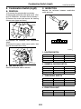
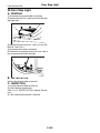
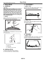
2. Headlight and Tail Light System
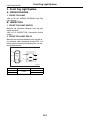
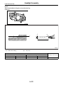
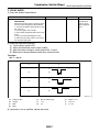
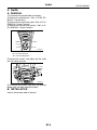
3. TAIL AND ILLUMINATION RELAY
Measure the resistance between tail and illumination relay terminals when connecting terminal No. 4
to battery positive terminal and terminal No. 3 to
battery ground terminal.
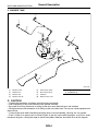
A: WIRING DIAGRAM
1. HALOGEN TYPE HEADLIGHT
<Ref. to WI-141, WIRING DIAGRAM, Headlight
System.>
(1)
2. CLEARANCE LIGHT AND ILLUMINATION LIGHT
(2)
<Ref. to WI-147, WIRING DIAGRAM, Clearance
Light and Illumination Light System.>
(3)
B: INSPECTION
(2)
(1)
(3)
(4)
(4)
LI-00001
1. HEADLIGHT SWITCH
<Ref. to LI-9, INSPECTION, Combination Switch
(Light).>
Current
Flow
No flow
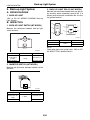
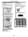
2. HEADLIGHT RELAY
Measure the resistance between headlight relay
terminals when connecting terminal No. 4 to battery
positive terminal and terminal No. 3 to battery
ground terminal.
(1)
(2)
(1)
(3)
(4)
(2)
(3)
(4)
LI-00001
Current
Flow
No flow
Terminal No.
1 and 2
Standard
Less than 1 Ω
More than 1 MΩ
LI-3
Terminal No.
1 and 2
Standard
Less than 1 Ω
More than 1 MΩ
Front Fog Light System
LIGHTING SYSTEM
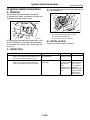
3. Front Fog Light System
A: WIRING DIAGRAM
1. FRONT FOG LIGHT
<Ref. to WI-144, WIRING DIAGRAM, Front Fog
Light System.>
B: INSPECTION
1. FRONT FOG LIGHT SWITCH
Measure the resistance between front fog light
switch terminals.
<Ref. to LI-9, INSPECTION, Combination Switch
(Light).>
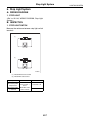
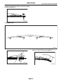
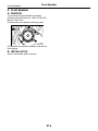
2. FRONT FOG LIGHT RELAY
Measure the resistance between front fog light relay terminals when connecting terminal No. 4 to
battery positive terminal and terminal No. 3 to battery ground terminal.
(1)
(2)
(1)
(3)
(4)
(2)
(3)
(4)
LI-00001
Current
Flow
No flow
Terminal No.
1 and 2
Standard
Less than 1 Ω
More than 1 MΩ
LI-4
Turn Signal Light and Hazard Light System
LIGHTING SYSTEM
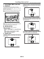
4. Turn Signal Light and Hazard
Light System
A: WIRING DIAGRAM
1. TURN SIGNAL LIGHT AND HAZARD
LIGHT SYSTEM
<Ref. to WI-151, WIRING DIAGRAM, Turn Signal
Light and Hazard Light System.>
B: INSPECTION
1. TURN SIGNAL SWITCH
<Ref. to LI-9, INSPECTION, Combination Switch
(Light).>
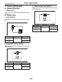
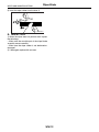
2. HAZARD SWITCH
Measure the resistance between hazard switch terminals.
4
3 2
1
LI-00261
Switch position
OFF
ON
Terminal No.
2 and 3
Standard
More than 1 MΩ
Less than 1 Ω
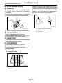
3. TURN SIGNAL LIGHT AND HAZARD
LIGHT MODULE
Connect the battery and turn signal light bulb to the
module. The module is properly functioning if it
blinks when power is supplied to the circuit.
3
2 1
8 7 6 5 4
LI-00262
LI-5
Back-up Light System
LIGHTING SYSTEM
5. Back-up Light System
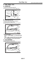
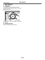
3. BACK-UP LIGHT RELAY (5AT MODEL)
A: WIRING DIAGRAM
Measure the resistance between back-up light relay terminals when connecting terminal No. 4 to
battery positive terminal and terminal No. 3 to battery ground terminal.
1. BACK-UP LIGHT
<Ref. to WI-145, WIRING DIAGRAM, Back-up
Light System.>
B: INSPECTION
(1)
1. BACK-UP LIGHT SWITCH (MT MODEL)
(2)
(1)
(3)
(4)
(2)
Measure the resistance between back-up light
switch terminals.
(3)
(4)
LI-00001
2 1
Current
Flow
No flow
Terminal No.
1 and 2
Standard
Less than 1 Ω
More than 1 MΩ
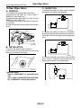
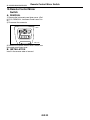
2. INHIBITOR SWITCH (4AT MODEL)
Measure the resistance between inhibitor switch
terminals.
6 5 4 3 2 1
12 11 10 9 8 7
LI-00005
Switch position
When the selector lever is in “R”
range
Other positions
Terminal No.
1 and 2
1 and 2
Standard
Less than 1 Ω
More than 1 MΩ
NOTE:
Check other than back-up light relay. <Ref. to 4AT48, INSPECTION, Inhibitor Switch.>
LI-00263
Switch position
When shift lever is
set in reverse
position
Other positions
Terminal No.
Standard
Less than 1 Ω
More than 1 MΩ
LI-6
Stop Light System
LIGHTING SYSTEM
6. Stop Light System
A: WIRING DIAGRAM
1. STOP LIGHT
<Ref. to WI-146, WIRING DIAGRAM, Stop Light
System.>
B: INSPECTION
1. STOP LIGHT SWITCH
Measure the resistance between stop light switch
terminals.
(1)
2 1
(2)
2 1
4 3
LI-00265
(1) Model without cruise control
(2) Model with cruise control
Switch position
When brake pedal
is depressed
When brake pedal
is released
Terminal No.
Model without
cruise control: 1
and 2
Model with cruise
control: 2 and 3
Standard
Less than 1 Ω
More than 1 MΩ
LI-7
Room Light System
LIGHTING SYSTEM
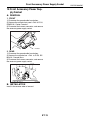
7. Room Light System
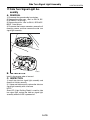
3. TRUNK ROOM LIGHT SWITCH
A: WIRING DIAGRAM
Measure the resistance between trunk room light
switch terminals.
1. ROOM LIGHT
<Ref. to WI-153, WIRING DIAGRAM, Interior Light
System.>
3 2 1
B: INSPECTION
1. DOOR SWITCH
Measure the resistance between door switch terminals.
LI-00277
Switch position
When trunk lid is
opened
When trunk lid is
closed
1
2
3
LI-00007
Switch position
When door is
opened
When door is
closed
Terminal No.
Standard
Less than 1 Ω
1 and 3
More than 1 MΩ
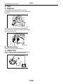
2. REAR GATE LATCH SWITCH
Measure the resistance between rear gate latch
switch terminals.
1
2
LI-00276
Switch position
When rear gate is
opened
When rear gate is
closed
Terminal No.
Standard
Less than 1 Ω
1 and 2
More than 1 MΩ
LI-8
Terminal No.
Standard
Less than 1 Ω
1 and 3
More than 1 MΩ
Combination Switch (Light)
LIGHTING SYSTEM
8. Combination Switch (Light)
C: INSPECTION
A: REMOVAL
Measure the resistance between combination
switch terminals.
1) Disconnect the ground cable from battery.
2) Remove the instrument panel lower cover. <Ref.
to EI-56, REMOVAL, Instrument Panel Assembly.>
3) Remove the screws and remove the steering
column cover (upper and lower).
SL-00258
4) Disconnect the connector from combination
switch.
5) Remove the screws which secure switch, then
remove the combination switch.
8
17
7 6 5 4 3
2
16 15 14 13 12 11 10
1
9
LI-00434
1. LIGHTING SWITCH
OFF
OFF
Switch position
OFF
Tail
Head
Terminal No.
—
14 and 16
13, 14 and 16
Standard
More than 1 MΩ
Less than 1 Ω
Less than 1 Ω
2. DIMMER & PASSING SWITCH
LI-00331
B: INSTALLATION
Switch position
Passing
Low beam
High beam
Install in the reverse order of removal.
Terminal No.
7, 8 and 16
17 and 16
7 and 16
Standard
Less than 1 Ω
Less than 1 Ω
Less than 1 Ω
3. TURN SIGNAL SWITCH
Switch position
Left
Neutral
Right
Terminal No.
1 and 2
—
2 and 3
Standard
Less than 1 Ω
More than 1 MΩ
Less than 1 Ω
4. FRONT FOG LIGHT
Switch position
OFF
ON
LI-9
Terminal No.
—
10 and 11
Standard
More than 1 MΩ
Less than 1 Ω
Combination Base Switch Assembly
LIGHTING SYSTEM
9. Combination Base Switch
Assembly
2. PARKING SWITCH
Measure the resistance between parking switch
terminals.
A: REMOVAL
1) Remove the driver’s airbag module. <Ref. to AB16, REMOVAL, Driver’s Airbag Module.>
2) Remove the steering wheel. <Ref. to PS-14, REMOVAL, Steering Wheel.>
3) Remove the screws and remove the steering
column lower cover.
2 1
4 3
LI-00183
Switch position
OFF
ON
SL-00258
4) Remove the combination switch. <Ref. to LI-9,
REMOVAL, Combination Switch (Light).> <Ref. to
WW-6, REMOVAL, Combination Switch (Wiper).>
5) Remove the four screws and remove the roll
connector.
6) Remove the three screws.
LI-00271
7) Disconnect the connector and remove the combination base switch assembly.
B: INSTALLATION
1) Install in the reverse order of removal.
2) Before installing steering wheel, be sure the direction of roll connector is adjusted with steering.
<Ref. to AB-25, ADJUSTMENT, Roll Connector.>
C: INSPECTION
1. COMBINATION BASE SWITCH ASSEMBLY
Inspect the combination base switch assembly and
roll connector for crack or deformation. If any damage is found, replace with a new one.
LI-10
Terminal No.
2 and 4
1 and 4
Standard
Less than 1 Ω
Less than 1 Ω
Headlight Assembly
LIGHTING SYSTEM
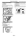
10.Headlight Assembly
A: REMOVAL
1) Disconnect the ground cable from battery.
2) Remove the air intake duct. (When removing the
headlight RH)
LI-00273
3) Remove the front grille. <Ref. to EI-24, REMOVAL, Front Grille.>
4) Remove the front bumper. <Ref. to EI-30, REMOVAL, Front Bumper.>
5) Disconnect each harness connector.
6) Remove the 5 bolts, disengage the clip, and then
detach the headlight assembly.
CAUTION:
Turn off the light before adjusting headlight
beam level. If the light is necessary to check
aiming, do not turn on for more than two minutes.
NOTE:
Before checking the headlight beam level, be sure
of the following:
• The area around the headlight has not sustained
any accident, damage or other type of deformation.
• Vehicle is parked on a level surface.
• The inflation pressure of tires is correct.
• Vehicle’s fuel tank is fully filled.
1) Bounce the vehicle several times to normalize
the suspension.
2) Make certain that someone is seated in the driver’s seat.
3) Turn the headlights on and then adjust the low
beam pattern.
LI-00452
B: INSTALLATION
Install in the reverse order of removal.
C: ADJUSTMENT
1. HEADLIGHT AIMING
NOTE:
Aiming of this headlight can be adjusted only in the
vertical direction. It cannot be adjusted in the horizontal direction.
LI-11
Headlight Assembly
LIGHTING SYSTEM
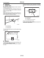
NOTE:
Adjust the headlight aiming by turning the adjusting
screw (A).
(A)
LI-00435
(A)
h
H
h
H
(B)
LI-00453
(A)
Bulb center marking
(B)
3 m (10 ft)
H mm (in)
Sedan
Except for OUTBACK
640 (25.20)
OUTBACK
707 (27.83)
Wagon
Except for OUTBACK
637 (25.08)
LI-12
h mm (in) at 3 m (10 ft)
OUTBACK
707 (27.83)
21 (0.83)
Headlight Bulb
LIGHTING SYSTEM
11.Headlight Bulb
7) Remove the light bulb retaining spring (A) to remove bulb.
A: REMOVAL
1. HIGH BEAM AND LOW BEAM
(A)
CAUTION:
• Because the halogen bulb operates at a high
temperature, dirt and oil on the bulb surface reduces the bulb’s service life. Hold the flange
portion when replacing the bulb. Never touch
the glass portion.
• Do not leave the headlight without a bulb for
a long time. Dust, moisture, etc. entering the
headlight may affect its performance.
1) Disconnect the ground cable from battery.
2) Remove the air intake duct. (When removing the
headlight bulb RH).
LI-00279
B: INSTALLATION
Install in the reverse order of removal.
C: INSPECTION
1) Visually check the bulb for blow out.
2) Check the bulb specification.
<Ref. to LI-2, SPECIFICATION, General Description.>
3) If NG, replace the bulb with a new one.
LI-00273
3) Remove the battery cover. (When removing the
headlight bulb LH).
4) Tilt the washer tank filler neck. (When removing
the headlight bulb LH).
5) Disconnect the harness connector.
6) Remove the bulb assembly (A) to remove high
beam. To remove the low beam, remove the back
cover (B), and then go to Step 7.
(B)
(A)
LI-00437
LI-13
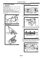
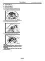
Front Turn Signal Light Bulb
LIGHTING SYSTEM
12.Front Turn Signal Light Bulb
A: REMOVAL
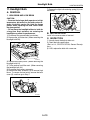
1) When removing the turn signal light bulb, fully
turn the steering wheels to opposite direction from
desired turn signal light bulb.
(3)
(2)
(1)
LI-00311
(1) Turn the steering wheel fully.
(2) Mud guard
(3) Front turn signal light
2) Turn the mud guard inward.
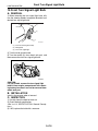
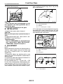
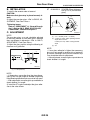
3) Turn the socket (A) from wheel arch part, and
then remove the front turn signal light bulb.
(A)
LI-00438
CAUTION:
For 5AT model, remove the turn signal light
bulb LH from engine compartment with removing battery, because it can not be removed from
wheel arch part.
B: INSTALLATION
Install in the reverse order of removal.
C: INSPECTION
1) Visually check the bulb for blow out.
2) Check the bulb specification.
<Ref. to LI-2, SPECIFICATION, General Description.>
3) If NG, replace the bulb with a new one.
LI-14
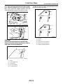
Parking Light Bulb
LIGHTING SYSTEM
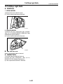
13.Parking Light Bulb
A: SPECIFICATION
The parking light bulb is integrated into front turn
signal light bulb as a unit; therefore, refer to “Front
Turn Signal Light Bulb” for removal procedure.
<Ref. to LI-14, REMOVAL, Front Turn Signal Light
Bulb.>
LI-15
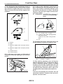
Front Side Marker Light Bulb
LIGHTING SYSTEM
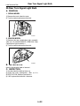
14.Front Side Marker Light Bulb
A: SPECIFICATION
The front marker light bulb is integrated into front
turn signal light bulb as a unit; therefore, refer to
“Front Turn Signal Light Bulb” for removal procedure. <Ref. to LI-14, REMOVAL, Front Turn Signal
Light Bulb.>
LI-16
Front Fog Light Assembly
LIGHTING SYSTEM
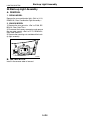
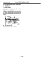
15.Front Fog Light Assembly
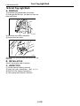
2) Remove the two clips, and then turn over the
lower mud guard.
A: REMOVAL
1. EXCEPT FOR OUTBACK MODEL
1) Disconnect the ground cable from battery.
2) Remove the front fog light cover (A).
(A)
LI-00288
3) Disconnect the harness connector.
4) Remove the mounting nuts and clips, and then
detach the fog light assembly by pulling it.
LI-00287
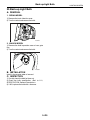
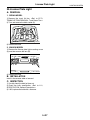
3) Disengage the two clips, and then turn over the
lower mud guard.
LI-00454
B: INSTALLATION
Install in the reverse order of removal.
LI-00288
4) Disconnect the harness connector.
5) Remove the mounting bolts, and then detach the
fog light assembly by pulling it.
LI-00289
2. OUTBACK MODEL
1) Disconnect the ground cable from battery.
LI-17
Front Fog Light Bulb
LIGHTING SYSTEM
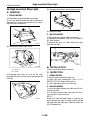
16.Front Fog Light Bulb
A: REMOVAL
1) Disconnect the ground cable from battery.
2) Disengage the two clips, and then turn over the
lower mud guard.
LI-00288
3) Disconnect the harness connector.
4) Remove the back cover.
LI-00291
5) Remove the spring retainer then detach the fog
light bulb.
B: INSTALLATION
Install in the reverse order of removal.
C: INSPECTION
1) Visually check the bulb for blow out.
2) Check the bulb specification. <Ref. to LI-2,
SPECIFICATION, General Description.>
3) If NG, replace the bulb with a new one.
LI-18
Side Turn Signal Light Assembly
LIGHTING SYSTEM
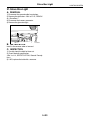
17.Side Turn Signal Light Assembly
A: REMOVAL
1) Disconnect the ground cable from battery.
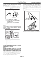
2) Remove the scalp caps. <Ref. to GW-18, REPLACEMENT, Scalp Cap.>
3) Remove the mirror. <Ref. to GW-21, REPLACEMENT, Outer Mirror.>
4) Disconnect the harness connector, remove the 3
mounting screws and then remove the side turn
signal light assembly.
LI-00293
B: INSTALLATION
Install in the reverse order of removal.
C: INSPECTION
1) Install the side turn signal light assembly and
check that it blinks normally.
2) If it does not blink normally, replace the side turn
signal light assembly with a new one.
NOTE:
Since LED (Light Emitting Diode) is used for side
turn signal light, replace the side turn signal light
assembly when the LED is powered off.
LI-19
Rear Combination Light Assembly
LIGHTING SYSTEM
18.Rear Combination Light Assembly
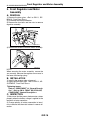
4) Remove the two bolts, and then detach the rear
combination light by pulling it to the rear side of vehicle.
A: REMOVAL
1. SEDAN MODEL
1) Disconnect the ground cable from battery.
2) Remove the trunk room side trim. <Ref. to EI-70,
REMOVAL, Trunk Room Trim.>
3) Remove the four nuts, and then detach the rear
combination light after disconnecting the connector.
LI-00296
5) Remove the rear combination light after turning
the socket of tail/stop light bulb and rear turn signal
light bulb to remove the bulbs.
B: INSTALLATION
Install in the reverse order of removal.
LI-00294
2. WAGON MODEL
1) Disconnect the ground cable from battery.
2) Remove the clips.
LI-00295
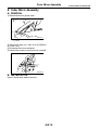
3) While pressing the portion (A), insert your finger
or flat-tip screwdriver wrapped with tape into the
clearance (B) to remove pawls in the order of (C),
(D), (E), and remove the rear combination cover.
(E)
(C)
(A)
(D)
(B)
LI-00284
LI-20
Tail/Stop Light Bulb
LIGHTING SYSTEM
19.Tail/Stop Light Bulb
A: REMOVAL
1. SEDAN MODEL
1) Remove the trunk side trim cover.
2) Turn the socket and remove the bulb.
LI-00439
2. WAGON MODEL
1) Remove the rear combination light assembly.
<Ref. to LI-20, WAGON MODEL, REMOVAL, Rear
Combination Light Assembly.>
2) Turn the socket and remove the bulb.
LI-00440
B: INSTALLATION
Install in the reverse order of removal.
C: INSPECTION
1) Visually check the bulb for blow out.
2) Check the bulb specification. <Ref. to LI-2,
SPECIFICATION, General Description.>
3) If NG, replace the bulb with a new one.
LI-21
Rear Turn Signal Light Bulb
LIGHTING SYSTEM
20.Rear Turn Signal Light Bulb
A: REMOVAL
1. SEDAN MODEL
1) Remove the trunk side trim cover.
2) Turn the socket and remove the bulb.
LI-00441
2. WAGON MODEL
1) Remove the rear combination light assembly.
<Ref. to LI-20, WAGON MODEL, REMOVAL, Rear
Combination Light Assembly.>
2) Turn the socket and remove the bulb.
LI-00442
B: INSTALLATION
Install in the reverse order of removal.
C: INSPECTION
1) Visually check the bulb for blow out.
2) Check the bulb specification. <Ref. to LI-2,
SPECIFICATION, General Description.>
3) If NG, replace the bulb with a new one.
LI-22
Rear Side Marker Light Bulb
LIGHTING SYSTEM
21.Rear Side Marker Light Bulb
A: REMOVAL
1. SEDAN MODEL
Bulb is not equipped for sedan model, since it is reflex reflector type.
2. WAGON MODEL
1) Remove the rear combination light assembly.
<Ref. to LI-20, WAGON MODEL, REMOVAL, Rear
Combination Light Assembly.>
2) Turn the socket and remove the bulb.
LI-00450
B: INSTALLATION
Install in the reverse order of removal.
C: INSPECTION
1) Visually check the bulb for blow out.
2) Check the bulb specification. <Ref. to LI-2,
SPECIFICATION, General Description.>
3) If NG, replace the bulb with a new one.
LI-23
Back-up Light Assembly
LIGHTING SYSTEM
22.Back-up Light Assembly
A: REMOVAL
1. SEDAN MODEL
Remove the rear combination light. <Ref. to LI-20,
REMOVAL, Rear Combination Light Assembly.>
2. WAGON MODEL
1) Remove the rear gate trim. <Ref. to EI-68, REMOVAL, Rear Gate Trim.>
2) Disconnect the harness connectors and remove
the rear gate garnish. <Ref. to EI-75, REMOVAL,
Rear Gate Garnish.>
3) Remove the mounting nuts and detach the backup light assembly.
LI-00301
B: INSTALLATION
Install in the reverse order of removal.
LI-24
Back-up Light Bulb
LIGHTING SYSTEM
23.Back-up Light Bulb
A: REMOVAL
1. SEDAN MODEL
1) Remove the trunk side trim cover.
2) Turn the socket and remove the bulb.
LI-00443
2. WAGON MODEL
1) Remove the bulb inspection cover of rear gate
trim.
2) Turn the socket and remove the bulb.
LI-00305
B: INSTALLATION
Install in the reverse order of removal.
C: INSPECTION
1) Visually check the bulb for blow out.
2) Check the bulb specification. <Ref. to LI-2,
SPECIFICATION, General Description.>
3) If NG, replace the bulb with a new one.
LI-25
License Plate Light Assembly
LIGHTING SYSTEM
24.License Plate Light Assembly
A: REMOVAL
1. SEDAN MODEL
1) Remove the trunk lid garnish. <Ref. to EI-74,
REMOVAL, Trunk Lid Garnish.>
2) Remove the trunk lid trim. <Ref. to EI-70,
TRUNK LID TRIM, REMOVAL, Trunk Room Trim.>
3) Turn and remove the bulb socket (A). Disengage
the clip (B) and remove the license plate light assembly.
(B)
(B)
(A)
LI-00306
B: INSTALLATION
Install in the reverse order of removal.
LI-26
License Plate Light
LIGHTING SYSTEM
25.License Plate Light
A: REMOVAL
1. SEDAN MODEL
1) Remove the trunk lid trim. <Ref. to EI-70,
TRUNK LID TRIM, REMOVAL, Trunk Room Trim.>
2) Turn and remove the bulb socket (A).
(A)
LI-00307
3) Remove the bulb.
2. WAGON MODEL
1) Remove the license plate light mounting screw
(A) and then remove the lens (B).
(B)
(A)
(B)
(A)
LI-00308
2) Remove the bulb.
B: INSTALLATION
Install in the reverse order of removal.
C: INSPECTION
1) Visually check the bulb for blow out.
2) Check the bulb specification. <Ref. to LI-2,
SPECIFICATION, General Description.>
3) If NG, replace the bulb with a new one.
LI-27
High-mounted Stop Light
LIGHTING SYSTEM
26.High-mounted Stop Light
5) Disengage three claws and remove the lens (A).
A: REMOVAL
1. SEDAN MODEL
1) Disconnect the ground cable from battery.
2) Push the high-mounted stop light backward of
the vehicle (1), raise the rear portion of it (2) and remove the clips to remove it.
(2)
(A)
LI-00310
6) Remove the bulb.
2. WAGON MODEL
(1)
1) Disconnect the ground cable from battery.
2) Detach the roof spoiler. <Ref. to EI-40, REMOVAL, Roof Spoiler.>
3) Remove the nuts (A), then detach the highmounted stop light.
LI-00333
3) Remove the harness from clamp.
(A)
(A)
(2)
LI-00312
(1)
LI-00334
B: INSTALLATION
Install in the reverse order of removal.
(1) Harness
(2) Clamp
C: INSPECTION
4) Disengage two claws (A), pull out the highmounted stop light from the cover and remove the
claw (B).
(A)
1. SEDAN MODEL
1) Visually check the bulb for blow out.
2) Check the bulb specification. <Ref. to LI-2,
SPECIFICATION, General Description.>
3) If NG, replace the bulb with a new one.
2. WAGON MODEL
1) Install the high-mounted stop light to test if it illuminates normally.
2) If the high-mounted stop light does not illuminate, replace it with a new one.
(B)
LI-00309
NOTE:
Since LED (Light Emitting Diode) is used for the
high-mounted stop light of wagon model, replace
the high-mounted stop light assembly when the
LED is powered off.
LI-28
Spot Map Light
LIGHTING SYSTEM
27.Spot Map Light
C: INSPECTION
A: REMOVAL
1. SPOT MAP LIGHT BULB
1) Disconnect the ground cable from battery.
2) Remove the lens (A) and spot map light mounting screws (B).
1) Visually check the bulb for blow out.
2) Check the bulb specification. <Ref. to LI-2,
SPECIFICATION, General Description.>
3) If NG, replace the bulb with a new one.
2. SPOT MAP LIGHT SWITCH
Measure the resistance between spot map light
switch terminals.
Switch position
OFF
ON
(A)
LI-00313
• Model with sunroof
(B)
LI-00314
• Model without sunroof
(B)
(B)
LI-00320
3) Disconnect the harness connectors and remove
the spot map light.
B: INSTALLATION
Install in the reverse order of removal.
LI-29
Terminal No.
—
1 and 2
Standard
More than 1 MΩ
18±5.4 Ω
Room Light
LIGHTING SYSTEM
28.Room Light
2. ROOM LIGHT SWITCH
A: REMOVAL
Measure the resistance between room light switch
terminals.
1) Disconnect the ground cable from battery.
2) Remove the lens (A) and mounting screws (B).
3 2 1
(A)
LI-00257
LI-00315
(B)
Switch position
OFF
ON
DOOR
LI-00316
3) Disconnect the harness connector and remove
the room light.
B: INSTALLATION
Install in the reverse order of removal.
C: INSPECTION
1. ROOM LIGHT BULB
1) Visually check the bulb for blow out.
2) Check the bulb specification. <Ref. to LI-2,
SPECIFICATION, General Description.>
3) If NG, replace the bulb with a new one.
LI-30
Terminal No.
—
1 and 3
2 and 3
Standard
More than 1 MΩ
1.5±0.5 Ω
1.5±0.5 Ω
Luggage Room Light
LIGHTING SYSTEM
29.Luggage Room Light
A: REMOVAL
1) Disconnect the ground cable from battery.
2) Remove luggage room light body (A).
(A)
LI-00258
3) Disconnect the harness connector and remove
the lens.
B: INSTALLATION
Install in the reverse order of removal.
C: INSPECTION
1. LUGGAGE ROOM LIGHT BULB
1) Visually check the bulb for blow out.
2) Check the bulb specification. <Ref. to LI-2,
SPECIFICATION, General Description.>
3) If NG, replace the bulb with a new one.
2. LUGGAGE ROOM LIGHT SWITCH
Measure the resistance between luggage room
light switch terminals.
3
2
1
LI-00259
Switch position
OFF
ON
DOOR
Terminal No.
—
1 and 2
2 and 3
Standard
More than 1 MΩ
1.5±0.5 Ω
1.5±0.5 Ω
LI-31
Trunk Room Light
LIGHTING SYSTEM
30.Trunk Room Light
2. TRUNK LID SWITCH (TRUNK ROOM
LIGHT SWITCH)
A: REMOVAL
1) Disconnect the ground cable from battery.
2) Turn the trunk room light counterclockwise to
60° to remove it and disconnect the harness connector.
Measure the resistance between trunk lid switch
terminals.
3
2
1
LI-00290
Trunk lid position
Close
Open
LI-00321
3) Remove the bulb (A).
(A)
LI-00286
B: INSTALLATION
Install in the reverse order of removal.
C: INSPECTION
1. TRUNK ROOM LIGHT BULB
1) Visually check the bulb for blow out.
2) Check the bulb specification. <Ref. to LI-2,
SPECIFICATION, General Description.>
3) If NG, replace the bulb with a new one.
LI-32
Terminal No.
1 and 3
Standard
More than 1 MΩ
1.5±0.5 Ω
Glove Box Light
LIGHTING SYSTEM
31.Glove Box Light
A: REMOVAL
1) Disconnect the ground cable from battery.
2) Remove the glove box. <Ref. to EI-51, REMOVAL, Glove Box.>
3) Disconnect the harness connector.
4) Remove the glove box light.
LI-00323
B: INSTALLATION
Install in the reverse order of removal.
C: INSPECTION
1) Visually check the bulb for blow out.
2) Check the bulb specification.
<Ref. to LI-2, SPECIFICATION, General Description.>
3) If NG, replace the bulb with a new one.
LI-33
Door Step Light
LIGHTING SYSTEM
32.Door Step Light
A: REMOVAL
1) Disconnect the ground cable from battery.
2) Remove the lens (A), and then remove the door
step light bulb.
(A)
LI-00266
3) Remove the front door trim. <Ref. to EI-48, REMOVAL, Door Trim.>
4) Disconnect the harness connector.
5) Remove the mounting screw from rear side of
trim and remove the door step light.
LI-00267
B: INSTALLATION
Install in the reverse order of removal.
C: INSPECTION
1) Visually check the bulb for blow out.
2) Check the bulb specification.
<Ref. to LI-2, SPECIFICATION, General Description.>
3) If NG, replace the bulb with a new one.
LI-34
Ignition Switch Illumination
LIGHTING SYSTEM
33.Ignition Switch Illumination
5) Turn the ignition switch illumination connector to
left and disconnect it.
A: REMOVAL
1) Disconnect the ground cable from battery.
2) Remove the screws and detach the upper column cover and lower column cover.
(B)
(A)
(C)
LI-00343
(A) Ignition switch illumination connector
(B) Ignition switch illumination
(C) Immobilizer antenna connector
SL-00258
3) Remove the instrument panel lower cover. <Ref.
to EI-56, REMOVAL, Instrument Panel Assembly.>
4) Disconnect the ignition switch illumination connector (A).
B: INSTALLATION
Install in the reverse order of removal.
C: INSPECTION
1
2
Step
CHECK IGNITION SWITCH ILLUMINATION.
Make sure the ignition switch illumination illuminates when driver’s side door is open.
CHECK IGNITION SWITCH ILLUMINATION.
Make sure the ignition switch illumination
blinks when ignition switch is turned to ON.
Check
Yes
No
Does the ignition switch illumi- Ignition switch illu- Go to step 2.
nation illuminate?
mination is normal.
Does the ignition switch illumi- Check the funcnation blink?
tion setting of body
integrated unit.
<Ref. to
LAN(diag)-2, Basic
Diagnostic Procedure.>
LI-35
Check the ignition
switch illumination
circuit. <Ref. to
SL-20, CHECK
IGNITION
SWITCH ILLUMINATION, INSPECTION, Keyless
Entry System.>
Ignition Switch Illumination
LIGHTING SYSTEM
LI-36
WIPER AND WASHER SYSTEMS
WW
1.
2.
3.
4.
5.
6.
7.
8.
9.
10.
11.
Page
General Description ....................................................................................2
Wiper and Washer System .........................................................................5
Combination Switch (Wiper)........................................................................6
Wiper Blade...............................................................................................10
Washer Tank and Motor............................................................................13
Front Wiper Arm........................................................................................14
Front Wiper Motor and Link.......................................................................15
Front Washer Nozzle ................................................................................16
Rear Wiper Arm ........................................................................................17
Rear Wiper Motor......................................................................................18
Rear Washer .............................................................................................19
General Description
WIPER AND WASHER SYSTEMS
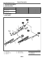
1. General Description
A: SPECIFICATION
Front wiper motor
Rear wiper motor
Input
Input
Pump type
Input
Pump type
Input
Front washer motor
Rear washer motor
12 V — 72 W or less
12 V — 42 W or less
Centrifugal
12 V — 36 W or less
Centrifugal
12 V — 36 W or less
B: COMPONENT
1. FRONT WIPER
T1
T1
(5)
(4)
T1
T1
T2
T2
(3)
(1)
(1)
(3)
(2)
(2)
WW-00215
(1)
(2)
(3)
Wiper rubber
Wiper blade ASSY
Wiper arm
(4)
(5)
Wiper link ASSY
Wiper motor ASSY
WW-2
Tightening torque: N⋅m (kgf-m, ft-lb)
T1: 6.0 (0.61, 4.4)
T2: 20 (2.0, 14.5)
General Description
WIPER AND WASHER SYSTEMS
2. REAR WIPER (WAGON MODEL)
(5)
(6)
T2
T1
(4)
(1)
(3)
(2)
WW-00167
(1)
(2)
(3)
Wiper rubber
Wiper blade ASSY
Wiper arm
(4)
(5)
(6)
Wiper arm cover
Cap
Wiper motor ASSY
WW-3
Tightening torque: N⋅m (kgf-m, ft-lb)
T1: 7.5 (0.77, 6.0)
T2: 8.0 (0.82, 5.9)
General Description
WIPER AND WASHER SYSTEMS
3. WASHER TANK
(1)
(1)
(2)
(4)
(1)
(2)
(3)
(7)
(6)
T
(8)
(7)
(5)
(2)
WW-00289
(1)
(2)
(3)
(4)
Washer nozzle
Washer hose
Washer tank
Washer tank cap
(5)
(6)
(7)
(8)
Front washer motor
Rear washer motor
Grommet
Washer motor cover
Tightening torque: N⋅m (kgf-m, ft-lb)
T: 6.0 (0.61, 4.4)
C: CAUTION
• Connect the connectors and hoses securely during reassembly.
• After reassembly, make sure functional parts operate smoothly.
• Be careful that wiring harnesses of airbag system pass near electrical parts and switches.
• Wiring harnesses and connectors of all airbag system are yellow color. Do not use a tester equipment on
these circuits.
• Care must be taken when connecting the piping hose so that no bending, jamming, etc. are caused.
• Even if a little oil or grease such as silicon oil gets in the tank and washer passages, an oil film is easily
formed on the glass, causing the wiper to chatter and judder, therefore, be careful not to let this happen.
WW-4
Wiper and Washer System
WIPER AND WASHER SYSTEMS
2. Wiper and Washer System
A: WIRING DIAGRAM
1. WIPER AND WASHER (FRONT)
<Ref. to WI-157, WIRING DIAGRAM, Front Wiper and Washer System.>
2. WIPER AND WASHER (REAR)
<Ref. to WI-158, WIRING DIAGRAM, Rear Wiper and Washer System.>
B: INSPECTION
Symptom
Wiper and washers do not operate.
Wipers do not operate in LO or HI.
Wipers do not operate in INT.
Washer motor does not operate.
Wipers do not operate when washer switch is ON.
Washer fluid spray does not operate properly.
Repair order
(1) Wiper fuse (Front: F/B No. 30, Rear: F/B No. 23)
(2) Combination switch
(3) Wiper motor assembly
(4) Wiring harness
(5) Body integrated unit (rear wiper only)
(1) Combination switch
(2) Wiper motor assembly
(3) Wiring harness
(1) Combination switch
(2) Wiper motor assembly
(3) Wiring harness
(4) Body integrated unit (rear wiper only)
(1) Washer switch
(2) Washer motor
(3) Wiring harness
(1) Washer motor
(2) Wiring harness
(1) Washer motor
(2) Washer hose and nozzle
WW-5
Combination Switch (Wiper)
WIPER AND WASHER SYSTEMS
3. Combination Switch (Wiper)
C: INSPECTION
A: REMOVAL
1. COMBINATION SWITCH
1) Disconnect the ground cable from battery.
2) Remove the instrument panel lower cover. <Ref.
to EI-50, REMOVAL, Instrument Panel Lower Cover.>
3) Remove the screw to remove steering column
cover (upper and lower).
1) Inspect the continuity between each connector
terminal.
SL-00258
4) Disconnect the connector from combination
switch.
5) Remove the three screws, and pull out the combination base switch assembly toward you.
9 8
18 17
7 6 5 4 3
16 15 14 13 12
2 1
11 10
WW-00046
Front
Rear
Switch position
OFF
INT
LO
HI
Washer ON
Washer ON
OFF
INT
ON
Washer ON
Terminal No.
7 and 16
7 and 16
7 and 17
8 and 17
2 and 11
2 and 12
—
2 and 13
2 and 10
2 and 12
12 and 10
2 and 10
Standard
Less than 1 Ω
Less than 1 Ω
Less than 1 Ω
Less than 1 Ω
Less than 1 Ω
Less than 1 Ω
More than 1 MΩ
Less than 1 Ω
Less than 1 Ω
Less than 1 Ω
2) If continuity is not as specified, replace the
switch.
LI -00332
6) Remove the switch securing screw to remove
combination switch.
B: INSTALLATION
Install in the reverse order of removal.
WW-6
Combination Switch (Wiper)
WIPER AND WASHER SYSTEMS
2. FRONT WIPER
1) Check with Subaru Select Monitor
Step
Check
CHECK INPUT SIGNAL TO BODY INTEIs the input signal normal?
GRATED UNIT.
When the front wiper switch is operated, check
the input signal using Subaru Select Monitor.
1) Connect the Subaru Select Monitor to data
link connector.
2) Turn the ignition switch to ON.
3) Select {Body Integrated Unit} from the main
menu.
4) Select {Current Data Display & Save}.
5) When the front wiper switch is set to LO or
HI, check the input signal.
1
Yes
End.
No
Replace the body
integrated unit.
<Ref. to SL-53,
Body Integrated
Unit.>
2) Intermittent operation inspection
(1) Turn the wiper switch to INT.
(2) Adjust the intermittent control switch to MAX.
(3) Apply the battery voltage to switch terminal No. 16 and 2.
(4) Measure the voltage between combination switch terminals.
Terminals
No. 7 — No. 2:
(A)
(B)
(F)
(C)
(G)
(H)
(F)
(D)
(G)
(I)
(F)
(E)
(G)
(J)
WW-00053
(A)
(B)
(C)
(D)
Switch position
Voltage
MIN.
MAX.
(E)
(F)
(G)
Non-intermittent type
12 V
0V
3) If operation is not as specified, replace the switch.
WW-7
(H)
(I)
(J)
Approx. 2 sec.
16±6 sec.
3±1 sec.
Combination Switch (Wiper)
WIPER AND WASHER SYSTEMS
3. REAR WIPER
1) Check with Subaru Select Monitor
1
2
Step
CHECK INPUT OF REAR WIPER.
Check the input from body integrated unit
using Subaru Select Monitor.
1) Connect the Subaru Select Monitor to data
link connector.
2) Turn the ignition switch to ON.
3) Select {Body Integrated Unit} from the main
menu.
4) Select {Current Data Display & Save}.
5) Check the input of rear wiper switch.
CHECK OUTPUT OF BODY INTEGRATED
UNIT.
When the rear wiper switch is operated, check
the output using Subaru Select Monitor.
1) Turn the ignition switch to ON.
2) Operate the rear wiper switch to set to each
position of ON and INT.
3) At this time, check the output of body integrated unit.
Check
Is the input normal?
Yes
Go to step 2.
No
Check the rear
wiper switch. <Ref.
to WW-6,
INSPECTION,
Combination
Switch (Wiper).>
When it is set to ON, is ON output continuously? When it is
set to INT, is ON/OFF output
repeatedly? (INT OFF time
(when vehicle parked): 12 seconds
Check the rear
wiper motor. <Ref.
to WW-18,
INSPECTION,
Rear Wiper
Motor.>
Replace the body
integrated unit.
<Ref. to SL-53,
Body Integrated
Unit.>
2) Rear wiper motor circuit check
1
2
3
Step
CHECK POWER SUPPLY CIRCUIT OF REAR
WIPER MOTOR.
1) Disconnect the harness connector of rear
wiper motor.
2) Turn the ignition switch to ACC.
3) Measure the voltage between the rear
wiper motor harness connector terminal and
chassis ground.
Connector & terminal
(D43) No. 1 (+) — Chassis ground (−):
CHECK GROUND CIRCUIT OF REAR WIPER
MOTOR.
1) Turn the ignition switch to OFF.
2) Measure the resistance between the rear
wiper motor harness connector terminal and
chassis ground.
Connector & terminal
(D43) No. 3 — Chassis ground:
CHECK HARNESS BETWEEN BODY INTEGRATED UNIT AND REAR WIPER MOTOR.
1) Turn the ignition switch to OFF.
2) Disconnect the harness connector of body
integrated unit.
3) Disconnect the harness connector of rear
wiper motor.
4) Measure the resistance between the harness connector terminals of body integrated
unit and rear wiper motor.
Connector & terminal
(B280) No. 1 — (D43) No. 2:
(B280) No. 8 — (D43) No. 4:
Check
Yes
Is the voltage more than 10 V? Go to step 2.
No
• Check the fuse
(No. 23 in fuse &
relay box).
• Check the fusible link (No. 6 in
main fuse box).
Is the resistance less than 10
Ω?
Go to step 3.
Repair the open
circuit of rear wiper
motor ground
cable.
Is the resistance less than 10
Ω?
Go to step 4.
Repair the open
circuit of harness
between body integrated unit and
rear wiper motor.
WW-8
Combination Switch (Wiper)
WIPER AND WASHER SYSTEMS
4
Step
Check
CHECK OPERATION OF REAR WIPER MO- Does the rear wiper motor
TOR.
rotate normally?
1) Remove the rear wiper motor.
2) Check the rear wiper motor. <Ref. to WW18, INSPECTION, Rear Wiper Motor.>
Yes
End.
NOTE:
Rear wiper intermittent time (AT model only)
Select lever position (AT
model only)
Rev
Except reverse mode
Vehicle speed (km/h (MPH))
Intermittent stopping time (sec.)
—
80 — (50 — )
50 — 80 (31 — 50)
20 — 50 (12 — 31)
0 — 20 (0 — 12)
Continuous operation
3
6
9
12
WW-9
No
Replace the rear
wiper motor.
Wiper Blade
WIPER AND WASHER SYSTEMS
4. Wiper Blade
C: DISASSEMBLY
A: REMOVAL
1. METAL TYPE
CAUTION:
When replacing wiper blades or etc., be sure to
stand up the driver side wiper arm first, then
passenger side wiper arm next. Also, when putting the wiper arms back, be sure to start with
passenger side first, then driver side next. Doing this in the reverse order may result in damage of passenger side wiper arm by hitting with
driver side wiper blade.
Pull side (A) of the wiper rubber stopper and remove the rubber from blade assembly.
1. FRONT
While pushing the locking clip (A) up, pull out the
blade from arm to the arrow direction.
2. RESIN TYPE
3
2
WW-00009
Pull the wiper rubber top slightly from the stopper
(A) and pull out fully.
(A)
2
(A)
3
1
WW-00064
2. REAR
Turn the blade in the direction of arrow (A) and remove it from arm.
WW-00143
D: ASSEMBLY
1. METAL TYPE
(1)
1) Insert the wiper rubber onto blade so that the
stopper is in the position shown in the figure.
(2)
(3)
(A)
(1)
(2)
(3)
(A)
WW-00207
Turn the wiper blade.
Wiper arm
Wiper blade
Installing part of wiper blade
WW-00230
B: INSTALLATION
1) Install in the reverse order of removal.
2) Confirm that the clip is locked securely.
WW-10
Wiper Blade
WIPER AND WASHER SYSTEMS
2) Make sure the wiper rubber is securely fastened
to the pull stopper (A).
WW-00037
2. RESIN TYPE
A
B
C
D
WW-00193
1) Insert the wiper rubber through the claw B.
2) Insert the wiper rubber until its top end protrudes
approx. 20 mm (0.79 in) from stopper D.
20 mm ( 0.79 in. )
A
B
D
WW-00145
WW-00146
WW-11
Wiper Blade
WIPER AND WASHER SYSTEMS
3) Insert the wiper rubber into the claw A.
A
WW-00147
E: INSPECTION
1) When the wiper does not perform well, inspect
the followings:
• Make sure the movable part of the wiper blade
assembly moves smoothly.
• Make sure the wiper rubber is not deformed or
damaged.
2) If damaged, replace with new one.
WW-12
Washer Tank and Motor
WIPER AND WASHER SYSTEMS
5. Washer Tank and Motor
D: ASSEMBLY
A: REMOVAL
1) Assemble in the reverse order of disassembly.
2) Confirm that water does not leak from installation area of motor.
1) Open the hood.
2) Disconnect the ground cable from battery.
3) Remove the front bumper. <Ref. to EI-30, REMOVAL, Front Bumper.>
4) Remove the clip holding washer water supply
tap.
E: INSPECTION
Apply battery voltage to the connector terminal of
the washer motor and make sure the motor operates.
2 1
WW-00173
WW-00170
5) Remove the two bolts and one nut, hose, connector and washer motor cover, and then remove
the washer tank.
WW-00171
B: INSTALLATION
Install in the reverse order of removal.
Tightening torque:
6.0 N⋅m (0.61 kgf-m, 4.4 ft-lb)
C: DISASSEMBLY
Pull out the washer motor from tank.
WW-00172
WW-13
Front Wiper Arm
WIPER AND WASHER SYSTEMS
6. Front Wiper Arm
C: ADJUSTMENT
A: REMOVAL
Operate the wiper once. Align the wiper blade to
ceramic print point mark (A) of front window panel.
CAUTION:
When replacing wiper blades or etc., be sure to
stand up the driver side wiper arm first, then
passenger side wiper arm next. Also, when putting the wiper arms back, be sure to start with
passenger side first, then driver side next. Doing this in the reverse order may result in damage of passenger side wiper arm by hitting with
driver side wiper blade.
1) Open the hood.
2) Remove the cap.
3) Remove the nut to remove wiper arm.
WW-00232
B: INSTALLATION
1) Install in the reverse order of removal.
2) Operate the wiper once.
3) Align the wiper blade to ceramic print point mark
(A) of front window panel.
(A)
WW-00048
Tightening torque:
Refer to “COMPONENT” of “General Description”.
<Ref. to WW-2, FRONT WIPER, COMPONENT, General Description.>
WW-14
(A)
WW-00048
Front Wiper Motor and Link
WIPER AND WASHER SYSTEMS
7. Front Wiper Motor and Link
2) When the battery is connected to the terminal of
connectors, confirm that the wiper motor operates
at high speed.
A: REMOVAL
1) Disconnect the ground cable from battery.
2) Remove the cowl panel. <Ref. to EI-39, REMOVAL, Cowl Panel.>
3) Disconnect the connector of wiper motor assembly.
4) Remove the bolt to remove wiper assembly.
3 2 1
5 4
WW-00219
3) Connect the battery to terminals of connector,
and remove the terminal connection with wiper motor rotated at low speed, and stop the wiper motor
through operation.
WW-00217
NOTE:
Wiper motor and wiper link can not be disassembled, because those are assembly part.
3 2 1
5 4
B: INSTALLATION
Install in the reverse order of removal.
Tightening torque:
Refer to “COMPONENT” of “General Description”.
<Ref. to WW-2, FRONT WIPER, COMPONENT, General Description.>
C: INSPECTION
WW-00220
4) Connect the battery and confirm that the wiper
motor stops at automatic stop position after the
wiper motor operates at low speed again.
1) When the battery is connected to the terminal of
connectors, confirm that the wiper motor operates
at low speed.
3 2 1
5 4
3 2 1
5 4
WW-00221
WW-00218
WW-15
Front Washer Nozzle
WIPER AND WASHER SYSTEMS
8. Front Washer Nozzle
A: REMOVAL
1) Remove the front hood insulator. <Ref. to EB13, FRONT HOOD INSULATOR, REMOVAL,
Front Hood.>
2) Hold the pawl of washer nozzle (A) toward the
arrow direction, and remove the washer nozzle.
Injection angle should be adjusted with 0.5 mm
(0.020 in) thickness steel scale. Use maximum
thickness of 0.5 mm steel scale, because the injection slit width of washer nozzle is 0.6 mm (0.024 in).
Adjusting with a flat tip driver may damage the injection slit and cause the faulty injection.
(1)
(3)
(A)
(2)
(4)
WW-00212
WW-00177
3) Remove the washer hose from washer nozzle.
B: INSTALLATION
1) Install in the reverse order of removal.
2) Adjust the washer nozzle position. <Ref. to WW16, ADJUSTMENT, Front Washer Nozzle.>
C: INSPECTION
• Make sure the nozzle and hose are not clogged.
• Make sure the hose is not bent.
D: ADJUSTMENT
1) Turn the wiper switch to OFF position.
2) While the vehicle is at standstill, adjust the washer injection position as shown in the figure.
Injection position:
A: 250 mm (9.84 in)
B: 435 mm (17.13 in)
A
A
B
(1)
WW-00161
(1) Nozzle
WW-16
(1)
(2)
(3)
(4)
Inside of washer nozzle injection
0.6 mm (0.024 in)
Steel scale
Max. 0.5 mm (0.020 in)
Rear Wiper Arm
WIPER AND WASHER SYSTEMS
9. Rear Wiper Arm
A: REMOVAL
1) Detach the wiper arm cover (A).
2) Remove the nut (B) to remove wiper arm.
(A)
(B)
WW-00179
B: INSTALLATION
1) Install in the reverse order of removal.
2) Operate the rear wiper once.
3) Align the blade with the marking (A) of glass.
(A)
WW-00229
Tightening torque:
Refer to “COMPONENT” of “General Description”.
<Ref. to WW-3, REAR WIPER (WAGON MODEL), COMPONENT, General Description.>
C: ADJUSTMENT
1) Operate the rear wiper once.
2) Align the blade with the marking (A) of glass.
(A)
WW-00229
WW-17
Rear Wiper Motor
WIPER AND WASHER SYSTEMS
10.Rear Wiper Motor
C: INSPECTION
A: REMOVAL
1) Connect the battery to wiper motor connector
and confirm that wiper motor operates.
1) Disconnect the ground cable from battery.
2) Remove the rear wiper arm. <Ref. to WW-17,
REMOVAL, Rear Wiper Arm.>
3) Remove the rear gate lower trim. <Ref. to EI-68,
REMOVAL, Rear Gate Trim.>
4) Disconnect the harness connector of wiper motor assembly.
5) Remove the bolts to remove wiper motor assembly (A).
2 1
4 3
WW-00186
(A)
2) Connect the battery to terminals of connector,
and remove the terminal connection with wiper motor rotated, and stop the wiper motor through operation.
2 1
4 3
WW-00183
B: INSTALLATION
1) Install in the reverse order of removal.
2) Be sure that the pivot cap with the arrow mark
facing up, as shown in the figure.
WW-00187
3) Connect the battery and confirm that the wiper
motor stops at automatic stop position after the
wiper motor operates at low speed again.
2 1
4 3
WW-00185
Tightening torque:
Refer to “COMPONENT” of “General Description”.
<Ref. to WW-3, REAR WIPER (WAGON MODEL), COMPONENT, General Description.>
WW-18
WW-00032
Rear Washer
WIPER AND WASHER SYSTEMS
11.Rear Washer
A: REMOVAL
1) Detach the roof spoiler. <Ref. to EI-40, REMOVAL, Roof Spoiler.>
2) Remove the washer hose from washer nozzle.
3) Push the pawl of nozzle from the reverse side of
roof spoiler with a flat tip screwdriver or equivalent,
and remove the washer nozzle.
WW-00214
B: INSTALLATION
Install in the reverse order of removal.
C: INSPECTION
• Make sure the nozzle and hose are not clogged.
• Make sure the hose is not bent.
• While the vehicle is at standstill, make sure the
washer injection position as shown in the figure.
NOTE:
Washer injection position can not be adjusted.
(1)
A
B
WW-00054
(1) Nozzle
(A) 70 mm (2.76 in)
(B) 70°
WW-19
Rear Washer
WIPER AND WASHER SYSTEMS
WW-20
ENTERTAINMENT
ET
1.
2.
3.
4.
5.
6.
7.
8.
9.
10.
11.
12.
13.
Page
General Description ....................................................................................2
Audio System ..............................................................................................3
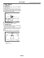
Front Accessory Power Supply Socket System ..........................................4
Audio ...........................................................................................................5
Front Speaker .............................................................................................6
Tweeter .......................................................................................................7
Rear Speaker ..............................................................................................8
Woofer.........................................................................................................9
Antenna.....................................................................................................10
Antenna Amplifier......................................................................................11
Noise Suppressor......................................................................................12
Front Accessory Power Supply Socket .....................................................13
Steering Satellite Switch ...........................................................................14
General Description
ENTERTAINMENT
1. General Description
A: CAUTION
• Before disassembling or reassembling parts, always disconnect the battery ground cable. When
replacing the audio, control unit, and other parts
provided with memory functions, record the memory contents before disconnecting the battery
ground cable. Otherwise, the memory will be
erased.
• Reassemble the parts in the reverse order of disassembly unless otherwise indicated.
• Adjust parts to the given specifications.
• Connect the connectors securely during reassembly.
• After reassembly, make sure the functional parts
operate smoothly.
B: PREPARATION TOOL
1. GENERAL TOOL
TOOL NAME
Circuit tester
Conductive silver composition
(DUPONT No. 4817 or
equivalent)
REMARKS
Used for measuring resistance and voltage.
Used for repairing antenna
wire.
ET-2
Audio System
ENTERTAINMENT
2. Audio System
A: WIRING DIAGRAM
<Ref. to WI-160, WIRING DIAGRAM, Audio System.>
B: INSPECTION
Symptom
No power coming in. (No display and no sound from speakers)
A specific speaker does not operate.
Audio generates noise with engine running.
AM and FM modes are weak or noisy.
Repair order
(1) Check the fuse and power supply for audio.
(2) Check the audio ground.
(3) Remove the audio and repair it.
(1) Check the speaker.
(2) Check the output circuit between audio and speaker.
(1) Check the audio ground.
(2) Check the generator.
(3) Check the ignition coil.
(4) Remove the audio and repair it.
(1) Check the antenna.
(2) Check the antenna amplifier.
(3) Check the noise suppressor.
(4) Check the audio ground.
(5) Remove the audio and repair it.
ET-3
Front Accessory Power Supply Socket System
ENTERTAINMENT
3. Front Accessory Power Supply Socket System
A: WIRING DIAGRAM
<Ref. to WI-162, WIRING DIAGRAM, Front Accessory Power Supply Socket System.>
ET-4
Audio
ENTERTAINMENT
4. Audio
A: REMOVAL
1) Disconnect the ground cable from battery.
2) Remove the console box. <Ref. to EI-53, REMOVAL, Console Box.>
3) Remove the console front panel. <Ref. to EI-54,
REMOVAL, Center Console.>
4) Remove the console side garnish. <Ref. to EI54, REMOVAL, Center Console.>
(A)
(B)
(B)
ET-00113
(A) Console front panel
(B) Console side garnish
5) Remove the screws, and slightly pull the audio
out from center console.
ET-00114
6) Disconnect the harness connector and antenna
feeder cord, and then remove the audio.
B: INSTALLATION
Install in the reverse order of removal.
ET-5
Front Speaker
ENTERTAINMENT
5. Front Speaker
A: REMOVAL
1) Disconnect the ground cable from battery.
2) Remove the front door trim. <Ref. to EI-48, REMOVAL, Door Trim.>
3) Remove the front speaker mounting screws.
ET-00080
4) Disconnect the harness connector and remove
front speaker.
B: INSTALLATION
Install in the reverse order of removal.
ET-6
Tweeter
ENTERTAINMENT
6. Tweeter
A: REMOVAL
1) Disconnect the ground cable from battery.
2) Remove the front door trim. <Ref. to EI-48, REMOVAL, Door Trim.>
3) Remove the tweeter mounting screws.
ET-00081
4) Disconnect the harness connector and remove
tweeter.
B: INSTALLATION
Install in the reverse order of removal.
ET-7
Rear Speaker
ENTERTAINMENT
7. Rear Speaker
A: REMOVAL
1) Disconnect the ground cable from battery.
2) Remove the rear door trim. <Ref. to EI-48, REMOVAL, Door Trim.>
3) Remove the rear speaker mounting screws.
ET-00084
4) Disconnect the harness connector and remove
rear speaker.
B: INSTALLATION
Install in the reverse order of removal.
ET-8
Woofer
ENTERTAINMENT
8. Woofer
A: REMOVAL
1) Disconnect the ground cable from battery.
2) Remove the hooks (A) and detach woofer cover.
<Ref. to EI-62, REMOVAL, Rear Quarter Trim.>
(A)
(A)
ET-00086
3) Remove the quarter lower trim. <Ref. to EI-62,
REMOVAL, Rear Quarter Trim.>
4) Remove the woofer bracket mounting clips (A)
and screws, and then remove the woofer bracket.
(A)
ET-00106
5) Disconnect the harness connector and detach
woofer.
B: INSTALLATION
Install in the reverse order of removal.
ET-9
Antenna
ENTERTAINMENT
9. Antenna
3) Apply conductive silver composition (DUPONT
No. 4817) on the broken portion with a drawing
pen.
A: INSPECTION
Measure the resistance between antenna terminal
and each antenna wire.
If an antenna wire is OK, resistance will be less
than 1 Ω. If an antenna wire is broken, resistance
will be more than 1 MΩ.
(A)
NOTE:
When checking the continuity, wind a piece of aluminum foil around the tip of tester probe and press
the foil against wire with your finger.
(B)
(C)
ET-00009
(A)
(A) Broken portion
(B) Masking film
(C) Conductive silver composition
4) Dry out the deposited portion.
5) After repair has been completed, measure the
resistance in repaired wire.
(C)
(B)
ET-00007
(A) Tester probe
(B) Aluminum foil
(C) Antenna wire
To locate the broken point, move the probe along
antenna wire.
ET-00008
B: REPAIR
1) Clean the antenna wire and surrounding area
with a cloth dampened by alcohol.
2) Paste a thin masking film on the glass along broken wire.
ET-10
Antenna Amplifier
ENTERTAINMENT
10.Antenna Amplifier
C: INSPECTION
A: REMOVAL
Measure the resistance of antenna amplifier.
• Sedan model
1. SEDAN MODEL
(1)-a
1) Disconnect the ground cable from battery.
2) Remove the rear quarter trim. <Ref. to EI-62,
SEDAN MODEL, REMOVAL, Rear Quarter Trim.>
3) Disconnect the harness connectors and terminals.
4) Remove the curtain airbag module. <Ref. to AB20, REMOVAL, Curtain Airbag Module.>
5) Remove the screw and detach antenna amplifier.
(1)-b
(2)
(1)-a
(1)-b
(2)-b
(3)
(3)-a
ET-00090
• Wagon model
(1)
(1)-b (1)-a
(3)-a
(2)-b
(2),(3)
ET-00088
2. WAGON MODEL
ET-00091
1) Disconnect the ground cable from battery.
2) Remove the rear gate trim. <Ref. to EI-68, REMOVAL, Rear Gate Trim.>
3) Disconnect the harness connectors and terminals.
4) Remove the screw and detach antenna amplifier.
ET-00089
B: INSTALLATION
Install in the reverse order of removal.
ET-11
Terminal No.
(1)-a and Amplifier body
(1)-b and Amplifier body
(2)-b and Amplifier body
(3)-a and Amplifier body
Standard
More than 10 kΩ
More than 10 kΩ
More than 10 kΩ
More than 10 kΩ
Noise Suppressor
ENTERTAINMENT
11.Noise Suppressor
A: REMOVAL
1. SEDAN MODEL
1) Disconnect the ground cable from battery.
2) Remove the rear quarter trim. <Ref. to EI-62,
SEDAN MODEL, REMOVAL, Rear Quarter Trim.>
3) Remove the curtain airbag module. <Ref. to AB20, REMOVAL, Curtain Airbag Module.>
4) Disconnect the harness connector from noise
suppressor.
5) Remove the harness clip.
6) Remove the screw and detach noise suppressor.
ET-00092
2. WAGON MODEL
1) Disconnect the ground cable from battery.
2) Remove the rear gate trim. <Ref. to EI-68, REMOVAL, Rear Gate Trim.>
3) Disconnect the harness connector from noise
suppressor.
4) Remove the screws and detach noise suppressor.
ET-00093
B: INSTALLATION
Install in the reverse order of removal.
ET-12
Front Accessory Power Supply Socket
ENTERTAINMENT
12.Front Accessory Power Supply Socket
A: REMOVAL
1. FRONT
1) Disconnect the ground cable from battery.
2) Remove the console front panel. <Ref. to EI-54,
REMOVAL, Center Console.>
3) Disconnect the harness connector, and remove
the accessory power supply socket.
ET-00094
2. REAR
1) Disconnect the ground cable from battery.
2) Remove the console box. <Ref. to EI-53, REMOVAL, Console Box.>
3) Disconnect the harness connector, and remove
the accessory power supply socket.
ET-00095
B: INSTALLATION
Install in the reverse order of removal.
ET-13
Steering Satellite Switch
ENTERTAINMENT
13.Steering Satellite Switch
A: REMOVAL
1) Disconnect the ground cable from battery.
2) Set the tire to the straight-ahead position.
3) Remove the airbag module. <Ref. to AB-16, REMOVAL, Driver’s Airbag Module.>
WARNING:
With the airbag module equipped, always refer
to “Airbag System” when performing the airbag
module repair service. <Ref. to AB-16, INSPECTION, Driver’s Airbag Module.>
4) Remove the steering wheel. <Ref. to PS-14, REMOVAL, Steering Wheel.>
5) Remove the cover from steering wheel.
6) Remove each one of satellite switch mounting
screw from the LH and RH side.
CS-00331
7) Remove the satellite switch.
B: INSTALLATION
Install in the reverse order of removal.
ET-14
Steering Satellite Switch
ENTERTAINMENT
C: INSPECTION
1 2 3 4 5
CS-00387
1
2
3
4
5
Step
MUTE SWITCH CONTINUITY CHECK.
1) Press the mute switch.
2) Measure the resistance between satellite
switch connector terminals.
Terminals
No. 1 — No. 2:
VOLUME SWITCH CONTINUITY CHECK.
1) Press the volume switch.
2) Measure the resistance between satellite
switch connector terminals.
Terminals
No. 1 — No. 2: Volume up
No. 1 — No. 2: Volume down
MODE SWITCH CONTINUITY CHECK.
1) Press the mode switch.
2) Measure the resistance between satellite
switch connector terminals.
Terminals
No. 1 — No. 2:
SEEK SWITCH CONTINUITY CHECK.
1) Press the seek switch.
2) Measure the resistance between satellite
switch connector terminals.
Terminals
No. 1 — No. 2: Seek up
No. 1 — No. 2: Seek down
CHECK SATELLITE SWITCH INSULATION.
1) Not to operate the satellite switch.
2) Measure the resistance between satellite
switch connector terminals.
Terminals
No. 1 — No. 2:
Check
Yes
Is the resistance approx. 22 Ω? Go to step 2.
No
Replace the satellite switch.
Is the resistance approx. 90 Ω? Go to step 3.
(Volume up) Is the resistance
approx. 200 Ω? (Volume down)
Replace the satellite switch.
Is the resistance approx. 360
Ω?
Go to step 4.
Replace the satellite switch.
Is the resistance approx. 690 Go to step 5.
Ω? (Seek up) Is the resistance
approx. 1.5 kΩ? (Seek down)
Replace the satellite switch.
Is the resistance approx. 4.7
kΩ?
Replace the satellite switch.
ET-15
Satellite switch is
normal.
Steering Satellite Switch
ENTERTAINMENT
ET-16
COMMUNICATION SYSTEM
COM
1.
2.
3.
4.
Page
General Description ....................................................................................2
Horn System ...............................................................................................3
Horn ............................................................................................................4
Horn Switch.................................................................................................5
General Description
COMMUNICATION SYSTEM
1. General Description
A: CAUTION
• Before disassembling or reassembling parts, always disconnect the battery ground cable from battery. When replacing audio, control module, and
other parts provided with memory functions, record
memory contents before disconnecting the battery
ground cable. Otherwise, the memory will be
erased.
• Reassemble in reverse order of disassembly, unless otherwise indicated.
• Adjust parts to the given specifications.
• Connect the connectors securely during reassembly.
• After reassembly, make sure functional parts operate smoothly.
B: PREPARATION TOOL
1. GENERAL TOOLS
TOOL
NAME
Circuit
tester
REMARKS
Used for measuring resistance and voltage.
COM-2
Horn System
COMMUNICATION SYSTEM
2. Horn System
A: WIRING DIAGRAM
1. HORN
<Ref. to WI-164, WIRING DIAGRAM, Horn System.>
B: INSPECTION
1. HORN RELAY
Measure the horn relay resistance between terminals (indicated in the table below) when connecting
the terminal No. 4 to battery positive terminal and
terminal No. 3 to battery ground terminal.
(1)
(2)
(1)
(3)
(4)
(2)
(3)
(4)
COM00001
Current
Flow
No Flow
Terminal No.
1 and 2
Standard
Less than 1 Ω
More than 1 MΩ
COM-3
Horn
COMMUNICATION SYSTEM
3. Horn
A: REMOVAL
1) Disconnect the ground cable from battery.
2) Remove the two clips and turn up the lower mud
guard RH.
LI-00288
3) Remove the horn bracket mounting bolt (A).
4) Disconnect the harness connector and remove
the horn assembly (B).
(A)
(B)
COM00039
B: INSTALLATION
Install in the reverse order of removal.
C: INSPECTION
With 12 V direct current supplied between horn terminals, check that the horn sounds properly.
COM00008
COM-4
Horn Switch
COMMUNICATION SYSTEM
4. Horn Switch
A: REMOVAL
WARNING:
Before servicing, be sure to read the notes in
AB section for proper handling of driver’s airbag module. <Ref. to AB-5, CAUTION, General
Description.>
NOTE:
Horn switch is a unit with the driver’s airbag module.
1) Disconnect the ground cable from battery.
2) Remove the driver’s airbag module. <Ref. to AB16, REMOVAL, Driver’s Airbag Module.>
B: INSTALLATION
Install in the reverse order of removal.
C: INSPECTION
Measure the resistance between horn switch terminal and airbag module bracket.
(1)
(2)
COM00037
(1) Airbag module bracket
(2) Horn switch terminal
Switch position
When horn switch
is pushed
When horn switch
is not pushed
Terminal No.
Resistance
Horn switch terminal and airbag
module bracket
Less than 1 Ω
More than 1 MΩ
COM-5
Horn Switch
COMMUNICATION SYSTEM
COM-6
GLASS/WINDOWS/MIRRORS
GW
1.
2.
3.
4.
5.
6.
7.
8.
9.
10.
11.
12.
13.
14.
15.
16.
17.
18.
19.
20.
21.
22.
Page
General Description ....................................................................................2
Power Window System ...............................................................................8
Power Window Control Switch ....................................................................9
Front Door Glass.......................................................................................11
Front Regulator and Motor Assembly .......................................................16
Remote Control Mirror System..................................................................17
Scalp Cap..................................................................................................18
Outer Mirror Assembly ..............................................................................19
Outer Mirror...............................................................................................21
Remote Control Mirror Switch ...................................................................22
Rear Door Glass .......................................................................................24
Rear Regulator and Motor Assembly ........................................................26
Windshield Glass ......................................................................................27
Rear Gate Glass .......................................................................................30
Rear Window Glass ..................................................................................31
Rear Window Defogger System................................................................32
Rear Window Defogger.............................................................................33
Rear Quarter Glass ...................................................................................35
Sun Roof Glass .........................................................................................36
Rearview Mirror.........................................................................................37
Wiper Deicer System ................................................................................38
Wiper Deicer Switch..................................................................................39
General Description
GLASS/WINDOWS/MIRRORS
1. General Description
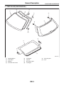
A: COMPONENT
1. FIXED GLASS (SEDAN MODEL)
(4)
(2)
(3)
(1)
(5)
(2)
(6)
(10)
(8)
(9)
(3)
(2)
(5)
(9)
(3)
(9)
(7)
(8)
(2)
(11)
GW-00404
(1)
(2)
(3)
(4)
Windshield glass
Dam rubber
Molding
Rearview mirror mount
(5)
(6)
(7)
(8)
Locating pin
Rear window glass
Six light glass
Bracket
GW-2
(9)
(10)
(11)
Clip
Seal
Spacer
General Description
GLASS/WINDOWS/MIRRORS
2. FIXED GLASS (WAGON MODEL)
(2)
(4)
(1)
(3)
(5)
(8)
(9)
(8)
(10)
(6)
(7)
(6)
(2)
GW-00405
(1)
(2)
(3)
(4)
Windshield glass
Dam rubber
Molding
Rearview mirror mount
(5)
(6)
(7)
(8)
Locating pin
Fastener
Rear quarter glass
Locating pin
GW-3
(9)
(10)
Rear gate glass
Seal
General Description
GLASS/WINDOWS/MIRRORS
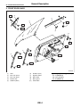
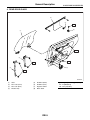
3. FRONT DOOR GLASS
T3
(9)
(4)
(1)
T1
T3
(6)
T3
(5)
(10)
T1
T1
(7)
(3)
T2
(2)
T1
T2
(8)
T2
T2
GW-00256
(1)
(2)
(3)
(4)
(5)
Glass
Door sash (Front)
Door sash (Rear)
Weather strip
Stabilizer (Outer)
(6)
(7)
(8)
(9)
(10)
Stabilizer (Inner)
Regulator ASSY
Motor ASSY
Mirror gusset
Guide ASSY
GW-4
Tightening torque: N⋅m (kgf-m, ft-lb)
T1: 7.4 (0.75, 5.5)
T2: 13.7 (1.4, 10.1)
T3: 5.9 (0.60, 4.4)
General Description
GLASS/WINDOWS/MIRRORS
4. REAR DOOR GLASS
(4)
(5)
T1
(6)
(1)
T1
(7)
(3)
T1
T2
(8)
(2)
T2
GW-00257
(1)
(2)
(3)
(4)
Glass
Door sash (Front)
Door sash (Rear)
Weather strip
(5)
(6)
(7)
(8)
Stabilizer (Outer)
Stabilizer (Inner)
Regulator ASSY
Motor ASSY
GW-5
Tightening torque: N⋅m (kgf-m, ft-lb)
T1: 7.4 (0.75, 5.5)
T2: 13.7 (1.4, 10.1)
General Description
GLASS/WINDOWS/MIRRORS
5. MIRROR
(3)
(2)
(A)
(6)
(1)
(5)
(4)
(3)
(2)
(B)
T1
(1)
GW-00386
(A)
Model with side turn signal light
(B)
Model without side turn signal light
(1)
(2)
(3)
Outer mirror
Mirror
Scalp cap
(4)
(5)
(6)
Side turn signal light
Rearview mirror
Mount
Tightening torque: N⋅m (kgf-m, ft-lb)
T1: 1.9 (0.19, 1)
B: CAUTION
• When electrical connectors are disconnected, always conduct an operational check after connecting them
again.
• Avoid impact and damage to the glass.
GW-6
General Description
GLASS/WINDOWS/MIRRORS
C: PREPARATION TOOL
1. SPECIAL TOOL
ILLUSTRATION
TOOL NUMBER
61299AE000
DESCRIPTION
SPACER
REMARKS
Used for adjusting the upper end position of front
door glass. (Glass thickness: 5 mm (0.197 in))
SPACER
Used for adjusting the upper end position of rear
door glass. (Glass thickness: 4 mm (0.157 in))
ST61299AE000
61299AE010
ST61299AE010
2. GENERAL TOOL
TOOL NAME
Circuit tester
Piano wire
Windshield glass knife
REMARKS
Used for checking voltage and continuity.
Used for removing the window glass.
Used for removing the window glass.
GW-7
Power Window System
GLASS/WINDOWS/MIRRORS
2. Power Window System
A: WIRING DIAGRAM
<Ref. to WI-165, Power Window System.>
B: INSPECTION
Symptom
All power windows do not operate.
One window does not operate.
“Window Lock” does not operate.
Repair order
(1) Fuse (SBF-4)
(2) Power window circuit breaker
(3) Power window relay
(4) Wiring harness
(5) Body integrated unit
(1) Power window main switch
(2) Power window sub switch
(3) Power window motor
(4) Wiring harness
Power window main switch
GW-8
Power Window Control Switch
GLASS/WINDOWS/MIRRORS
3. Power Window Control
Switch
2. SUB SWITCH
A: REMOVAL
1. MAIN SWITCH
1) Disconnect the ground cable from battery.
2) Remove the front door trim. <Ref. to EI-48, REMOVAL, Door Trim.>
3) Disconnect the harness connector.
4) Remove the screws from the reverse side of
front door trim to remove the power window main
switch.
1) Disconnect the ground cable from battery.
2) Remove the door trim. <Ref. to EI-48, REMOVAL, Door Trim.>
3) Disconnect the connector.
4) Remove the screws from the reverse side of
door trim to remove the power window sub switch.
GW-00388
B: INSTALLATION
1. MAIN SWITCH
Install in the reverse order of removal.
GW-00387
2. SUB SWITCH
Install in the reverse order of removal.
C: INSPECTION
1. MAIN SWITCH
Measure switch resistance.
6 5 4
3 2 1
14 13 12 11 10 9 8 7
GW-00406
Driver’s seat
Passenger’s seat
Switch position
UP
OFF
DOWN
AUTO DOWN
Terminal No.
10 and 2, 7 and 1
2 and 7, 1 and 2
10 and 1, 7 and 2
10 and 1, 7 and 2
Standard
Less than 1 Ω
Less than 1 Ω
Less than 1 Ω
Less than 1 Ω
Switch position
UP
OFF
DOWN
Terminal No.
10 and 14, 7 and 11
7 and 14, 7 and 11
10 and 11, 7 and 14
Standard
Less than 1 Ω
Less than 1 Ω
Less than 1 Ω
GW-9
Power Window Control Switch
GLASS/WINDOWS/MIRRORS
Rear seat RH
Rear seat LH
Switch position
UP
OFF
DOWN
Terminal No.
10 and 13, 7 and 12
7 and 13, 7 and 12
10 and 12, 7 and 13
Standard
Less than 1 Ω
Less than 1 Ω
Less than 1 Ω
Switch position
UP
OFF
DOWN
Terminal No.
10 and 8, 7 and 9
7 and 8, 7 and 9
9 and 10, 7 and 8
Standard
Less than 1 Ω
Less than 1 Ω
Less than 1 Ω
Terminal No.
2 and 3, 4 and 5
1 and 2, 4 and 5
1 and 2, 3 and 4
Standard
Less than 1 Ω
Less than 1 Ω
Less than 1 Ω
Replace the main switch if faulty.
2. SUB SWITCH
Measure switch resistance.
5 4 3 2 1
GW-00407
Passenger’s seat and
rear
Switch position
UP
OFF
DOWN
Replace the sub switch if faulty.
GW-10
Front Door Glass
GLASS/WINDOWS/MIRRORS
4. Front Door Glass
6) Remove the stabilizer.
A: REMOVAL
1) Remove the front door trim. <Ref. to EI-48, REMOVAL, Door Trim.>
2) Remove the sealing cover. <Ref. to EB-20, REMOVAL, Front Sealing Cover.>
3) Remove the outer mirror assembly. <Ref. to
GW-19, REMOVAL, Outer Mirror Assembly.>
4) Remove the clip (A), and remove the front end of
weather strip.
GW-00263
7) Remove the clips (A), and remove the rear end
of weather strip.
(A)
(A)
GW-00261
5) Remove the gusset.
GW-00264
8) Remove the screw (A) from the rear end of
weather strip outer to remove weather strip outer.
(A)
GW-00265
9) Remove the screws to remove guide assembly.
10) Operate the power window switch to move
glass to position shown in the figure, and then remove the two nuts through service holes.
GW-00262
GW-00266
GW-11
Front Door Glass
GLASS/WINDOWS/MIRRORS
11) Remove the door glass.
sure of 25±5 N (2.5±0.5 kgf, 5.5±1.1 lb) to the
glass, then secure it.
(1)
F
(3)
A
A
(2)
(2)
A = A
GW-00267
GW-00063
CAUTION:
• Since the gear may be disengaged, do not
turn regulator in the closing direction after removal of the glass.
• Avoid impact and damage to the glass.
B: INSTALLATION
1) Install in the reverse order of removal.
CAUTION:
Make sure that glass stay is placed securely in
sash.
2) Adjust the front door glass. <Ref. to GW-12, ADJUSTMENT, Front Door Glass.>
(1) Fully closed position
(2) Stabilizer
(3) 10 — 15 mm (0.39 — 0.59 in)
4) For adjustment of clearance between front glass
and center pillar cover, loosen the nuts (A), and
move the glass sash back and forward until clearance becomes the value shown.
Tightening torque:
Refer to “COMPONENT” of “General Description”. <Ref. to GW-4, FRONT DOOR GLASS,
COMPONENT, General Description.>
C: ADJUSTMENT
(A)
(2)
(1)
(3)
NOTE:
Before adjustment, ensure that all adjusting bolts of
stabilizer, upper stopper and sash are loose and
door glass is raised so that it is in contact with
weather strip.
1) Temporarily tighten one adjusting bolt on one
side of rear sash at the midpoint of slotted hole in
the inner panel.
2) Temporarily tighten the regulator B-channel in a
position at the top of slotted hole.
3) Lower the door glass 10 — 15 mm (0.39 — 0.59
in) from fully closed position. While applying outward pressure of 45.0±5.0 N (4.5±0.5 kgf, 9.9±1.1
lb) (F) to upper edge of glass above midpoint of two
outer stabilizers, press the inner stabilizer at pres-
GW-00319
(1) Adjust a line parallel
(2) Sash
(3) Inner panel
(1)
(1)
A A
A-A
GW-00064
(1) 11 mm (0.433 in)
GW-12
Front Door Glass
GLASS/WINDOWS/MIRRORS
5) To adjust the upper end and lower end of center
pillar, loosen the stopper bolt (A) or nut (B) securing
door sash, move the stopper position until the
clearance between center pillar cover is equal.
6) Adjust so that the upper and lower ends of center pillar are the same size.
(1)
(3)
(2)
(5)
(5)
(A)
GW-00320
(2)
(4)
(5)
(B)
(1)
(5)
GW-00323
GW-00321
CAUTION:
Perform the measurement of clearance between center pillar at less than 50 mm (1.969 in)
from upper end of window glass.
(1)
(2)
(4)
(5)
(3)
GW-00322
(1)
(2)
(3)
(4)
(5)
Glass
Center pillar cover
Check point
50 mm (1.969 in)
11 mm (0.433 in)
GW-13
(1)
(2)
(3)
(4)
(5)
Narrow
Wide
Glass tilts too far rearward
Glass tilts too far forward
Stopper adjusting direction
Front Door Glass
GLASS/WINDOWS/MIRRORS
7) After adjusting the clearance between center pillar, up and down the glass several times to check
glass contact to stopper when glass is fully closed.
Adjust it to contact the front and rear stopper simultaneously.
(1)
(3)
9) For glass stroke adjustment, install the ST to
glass, close the door, and raise the glass with regulator until positional relationship between glass
and weather strip becomes as shown. And secure
the glass so that the upper stopper correctly touches the glass holder.
ST 61299AE000 SPACER (Glass thickness: 5
mm (0.197 in) for front door
glass)
(2)
(1)
A
(5)
A
(2)
(3)
(2)
GW-00336
(4)
(6)
(1)
(1) 3.2 — 4.8 mm (0.126 — 0.189 in)
(2) 3.0 mm (0.118 in): when replacing weather
stripe with a new one
5.5 mm (0.217 in): when re-using weather
stripe
(3) ST
GW-00324
(1) Narrow
(2) Wide
(3) When the stopper of door sash (rear) contacts
first
(4) When the stopper of door sash (front) contacts
first
(5) Raise B channel
(6) Lower B channel
For preventing wind noise, adjust the glass at the
position where tip of gusset is raised up a little.
(A)
8) For adjustment of the upper and lower ends of
center pillar, loosen the adjusting nut (A) of B-channel (B).
GW-00325
(A) 0 — 1.5 mm (0 — 0.059 in)
(B)
(A)
GW-00269
10) After stabilizer adjustment, carry out the glass
cohesion adjustment. First, visually ensure the positional relationship between retainer & molding
and glass of the roof side, and then begin with rear
sash adjustment. Install the ST to glass and adjust
two adjusting bolts alternately step by step to obtain dimensions shown below (cross-section A).
NOTE:
If two nuts are loosened at the same time, the sash
moves back and forth. Therefore, when one nut is
adjusted, secure the other.
GW-14
Front Door Glass
GLASS/WINDOWS/MIRRORS
11) Make the same adjustment of two adjusting
bolts of rear sash.
ST 61299AE000 SPACER (Glass thickness: 5
mm (0.197 in) for front door
glass)
(1)
14) After adjustment of the glass, close the door. If
there is a gap between outer lip of gusset and glass
surface, adjust the gap with adjusting bolt (A) in
lower fitting part of gusset to prevent generation of
wind noise.
15) During adjustment, loosen the other three
clamping bolts.
A
A
(3)
(2)
GW-00336
(1) 3.2 — 4.8 mm (0.126 — 0.189 in)
(2) 3.0 mm (0.118 in): when replacing weather
stripe with a new one
5.5 mm (0.217 in): when re-using weather
stripe
(3) ST
NOTE:
Do not tilt the sash bracket to inner panel during adjustment. Otherwise smooth regulator operation
cannot be achieved.
(A)
16) After adjustment, tighten the bolts and nuts.
(1)
(4)
(3)
(2)
(5)
GW-00270
(1)
(2)
(3)
(4)
(5)
GW-00271
Sash bracket
Rear sash
Adjust a line parallel
Sash
Inner panel
12) Make adjustment of front sash in the same
manner as that of rear sash.
NOTE:
Although front and rear sashes must, as a rule, be
adjusted in the same manner, in some door installation, the adjustment in a different manner may be
required. However, adjustment of one sash to the
maximum amount and the other to the minimum
amount is not permitted. Such adjustment may result in application of excessive load to regulator.
13) After adjustments, tighten the nuts.
GW-15
Front Regulator and Motor Assembly
GLASS/WINDOWS/MIRRORS
5. Front Regulator and Motor
Assembly
A: REMOVAL
1) Remove the door glass. <Ref. to GW-11, REMOVAL, Front Door Glass.>
2) Disconnect the motor connector.
3) Remove the four bolts and two nuts to remove
regulator assembly.
GW-00273
4) Remove the screws to remove motor assembly.
GW-00274
NOTE:
When removing the motor assembly, secure the
arm correctly, because the regulator arm moves in
the force of balancing spring.
B: INSTALLATION
1) Install in the reverse order of removal.
2) Adjust the front door glass. <Ref. to GW-12, ADJUSTMENT, Front Door Glass.>
Tightening torque:
Refer to “COMPONENT” of “General Description”. <Ref. to GW-4, FRONT DOOR GLASS,
COMPONENT, General Description.>
C: INSPECTION
1) Make sure that the power window motor rotates
properly when the battery voltage is applied to the
terminals of motor connector.
2) Change polarity of battery connection to terminals to ensure that the motor rotates in reverse direction.
GW-16
Remote Control Mirror System
GLASS/WINDOWS/MIRRORS
6. Remote Control Mirror System
A: WIRING DIAGRAM
<Ref. to WI-170, Remote Control Mirror System.>
B: INSPECTION
Symptom
All function does not operate.
One side of the mirror motor does not operate.
Mirror heater does not operate.
Repair order
(1) Fuse (F/B No. 6)
(2) Mirror switch
(3) Wiring harness
(1) Mirror switch
(2) Mirror motor
(3) Wiring harness
(1) Mirror switch
(2) Mirror heater
(3) Wiring harness
GW-17
Scalp Cap
GLASS/WINDOWS/MIRRORS
7. Scalp Cap
2. MODEL WITHOUT SIDE TURN SIGNAL
LIGHT
A: REPLACEMENT
1) Remove the mirror. <Ref. to GW-21, REPLACEMENT, Outer Mirror.>
2) Press-in the clips (A) from inside of door mirror.
1. MODEL WITH SIDE TURN SIGNAL
LIGHT
1) Remove the mirror. <Ref. to GW-21, REPLACEMENT, Outer Mirror.>
2) Press-in the upper side clips (A) from inside of
door mirror.
(A)
(A)
(A)
(A)
(A)
(A)
GW-00312
3) Pull the scalp cap frontward of door mirror, remove the upper side clips (A) and lower side hooks
(B), and then remove the scalp cap.
GW-00389
3) Pull the scalp cap frontward of door mirror, and
then remove the scalp cap.
4) Mate the backside clip (A) of scalp cap with the
clip hole of the outer mirror to install, and then push
the scalp cap in.
(A)
(A)
(A)
GW-00390
5) Install the scalp cap securely.
(B)
GW-00275
4) Insert the lower hooks (B) of scalp cap to door
mirror and push the upper clips (A) in.
(A)
(B)
GW-00276
5) Install the scalp cap securely.
CAUTION:
Do not remove the scalp cap forcibly. The lower
hooks may be damaged.
GW-18
Outer Mirror Assembly
GLASS/WINDOWS/MIRRORS
8. Outer Mirror Assembly
A: REMOVAL
1) Remove the mirror gusset cover.
: (1)
GW-00277
(1) Hook
2) Remove the door trim. <Ref. to EI-48, REMOVAL, Door Trim.>
3) Disconnect the mirror connector.
4) Remove the screws to remove mirror assembly.
GW-00278
B: INSTALLATION
Install in the reverse order of removal.
GW-19
Outer Mirror Assembly
GLASS/WINDOWS/MIRRORS
C: INSPECTION
Check that the rearview mirror moves properly when the battery voltage is applied to terminals.
• Model with side turn signal light
1 2
3
4 5 6 7 8
GW-00408
Switch position
OFF
UP
DOWN
LEFT
RIGHT
Terminal No.
—
6 (+) and 3 (−) or 8 (−)
3 (+) or 8 (+) and 6 (−)
7 (+) and 3 (−) or 8 (−)
3 (+) or 8 (+) and 7 (−)
• Model without side turn signal light
1
2
3 4 5 6
GW-00409
Switch position
OFF
UP
DOWN
LEFT
RIGHT
Terminal No.
—
4 (+) and 2 (−) or 6 (−)
2 (+) or 6 (+) and 4 (−)
5 (+) and 6 (−) or 2 (−)
6 (+) or 2 (+) and 5 (−)
Replace the outer mirror assembly if defective.
GW-20
Outer Mirror
GLASS/WINDOWS/MIRRORS
9. Outer Mirror
A: REPLACEMENT
1) Face the mirror upward.
2) Use a flat tip screwdriver to remove clip (A).
3) Lift the lower mirror up to remove hooks (B).
(A)
(B)
GW-00279
4) Disconnect the mirror heater connector from the
end of mirror. (Model with mirror heater)
GW-00280
5) Catch the hooks (A) and install clips (B).
(A)
(B)
GW-00281
CAUTION:
• When removing the mirror, be careful not to
damage the back side of mirror with a flat tip
screwdriver.
• When installing the mirror, insert the hook
and clip securely.
GW-21
Remote Control Mirror Switch
GLASS/WINDOWS/MIRRORS
10.Remote Control Mirror
Switch
A: REMOVAL
1) Remove the instrument panel lower cover. <Ref.
to EI-50, REMOVAL, Instrument Panel Lower Cover.>
2) Disconnect the connector.
L
R
OFF
GW-00391
3) Remove the remote control mirror switch from
instrument panel lower cover.
B: INSTALLATION
Install in the reverse order of removal.
GW-22
Remote Control Mirror Switch
GLASS/WINDOWS/MIRRORS
C: INSPECTION
1. REMOTE CONTROL MIRROR SWITCH
Move the remote control mirror switch to each position and check continuity between terminals.
7 6 5 4
3 2 1
16 15 14 13 12 11 10 9 8
GW-00283
• Change over switch R
Switch position
OFF
UP
DOWN
LEFT
RIGHT
Terminal No.
—
10 and 12, 15 and 14
10 and 15, 12 and 14
10 and 11, 15 and 14
10 and 15, 11 and 14
Standard
More than 1 MΩ
Less than 1 Ω
Less than 1 Ω
Less than 1 Ω
Less than 1 Ω
Terminal No.
—
10 and 8, 15 and 14
10 and 15, 8 and 14
10 and 9, 15 and 14
10 and 15, 9 and 14
Standard
More than 1 MΩ
Less than 1 Ω
Less than 1 Ω
Less than 1 Ω
Less than 1 Ω
• Change over switch L
Switch position
OFF
UP
DOWN
LEFT
RIGHT
Replace the remote control mirror switch if defective.
GW-23
Rear Door Glass
GLASS/WINDOWS/MIRRORS
11.Rear Door Glass
6) Operate the power window switch to move the
glass to position shown in the figure, and then remove the two nuts through service holes.
A: REMOVAL
1) Remove the rear door trim. <Ref. to EI-48, REMOVAL, Door Trim.>
2) Remove the sealing cover. <Ref. to EB-24, REMOVAL, Rear Sealing Cover.>
3) Remove the stabilizer.
GW-00287
7) Remove the rear sash retaining nuts (A) and
move rear sash (B) backward.
(A)
GW-00284
4) Remove the clips (A), and remove the front end
and rear end of weather strip.
(B)
GW-00288
8) Remove the door glass.
CAUTION:
• Since the gear may be disengaged, do not
turn regulator in the closing direction after removal of the glass.
• Avoid impact and damage to the glass.
(A)
(A)
GW-00285
5) Loosen the two screws to remove weather strip
outer.
GW-00286
GW-24
Rear Door Glass
GLASS/WINDOWS/MIRRORS
B: INSTALLATION
ST
1) Install in the reverse order of removal.
CAUTION:
Make sure that glass stay is placed securely in
sash.
2) Adjust the rear door glass. <Ref. to GW-25, ADJUSTMENT, Rear Door Glass.>
(1)
A
A
Tightening torque:
Refer to “COMPONENT” of “General Description”. <Ref. to GW-5, REAR DOOR GLASS,
COMPONENT, General Description.>
(3)
(2)
C: ADJUSTMENT
A-A
NOTE:
The rear door glass, as a rule, should be adjusted
in the same manner as front door glass, although
they are different in dimension. <Ref. to GW-12,
ADJUSTMENT, Front Door Glass.>
1) Adjust the glass position using the following dimensions as a guide line.
(1)
A
61299AE010 SPACER (Glass thickness: 4
mm (0.157 in) for rear door
glass)
GW-00337
(1) 3.2 — 4.8 mm (0.126 — 0.189 in)
(2) 3.0 mm (0.118 in): when replacing weather
stripe with a new one
5.5 mm (0.217 in): when re-using weather
stripe
(3) ST
NOTE:
• If rear glass adhesion is higher than necessary,
glass may get caught in weather strip of center pillar corner, resulting in early wear of weather strip.
Care should be taken for adjustment.
• After adjustment, move the glass up and down to
check whether it is caught.
(1)
A
A-A
GW-00067
(1) 11 mm (0.433 in)
NOTE:
• If dimensions are smaller than the given dimensions, glass may get caught in weather strip during
lifting/lowering operation and may not be fully open.
• After adjustment, move the glass up and down to
check whether it is caught.
2) Install the ST to glass and adjust the glass adhesion to the value shown.
GW-25