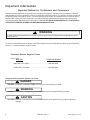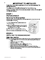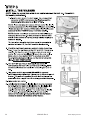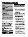
1
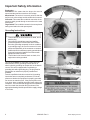
Service
This manual is to be used by qualified appliance
technicians only. Maytag does not assume any
responsibility for property damage or personal
injury for improper service procedures done by
an unqualified person.
Compact
Washer
This Base Manual covers general information
Refer to individual Technical Sheet
for information on specific models
This manual includes, but is
not limited to the following:
MAH2400AW*
16023430
Revision 0
©2004 Maytag Services
Important Information
Important Notices for Technicians and Consumers
Maytag will not be responsible for personal injury or property damage from improper service procedures. Pride and
workmanship go into every product to provide our customers with quality products. It is possible, however, that during
its lifetime a product may require service. Products should be serviced only by a qualified service technician who is
familiar with the safety procedures required in the repair and who is equipped with the proper tools, parts, testing
instruments and the appropriate service information. IT IS THE TECHNICIANS RESPONSIBILITY TO REVIEW ALL
APPROPRIATE SERVICE INFORMATION BEFORE BEGINNING REPAIRS.
!
WARNING
To avoid risk of severe personal injury or death, disconnect power before working/servicing on appliance to avoid
electrical shock.
To locate an authorized technician, please consult your telephone book or the dealer from whom you purchased this
product. For further assistance, please contact:
Customer Service Support Center
CAIR Center
Web Site
Telephone Number
WWW.MAYTAG.COM ............................................. 1-800-688-9900
CAIR Center in Canada ........................................... 1-800-688-2002
Recognize Safety Symbols, Words, and Labels
! DANGER
DANGER—Immediate hazards which WILL result in severe personal injury or death.
!
WARNING
WARNING—Hazards or unsafe practices which COULD result in severe personal injury or death.
!
CAUTION
CAUTION—Hazards or unsafe practices which COULD result in minor personal injury, product or property
damage.
2
16023430 Rev. 0
©2004 Maytag Services
Table of Contents
Important Information .................................................... 2
Important Safety Information ......................................... 4
General Information
Model Identification .................................................... 8
Serial Label Location ................................................. 8
Model Nomenclature .................................................. 9
Model Specifications ................................................. 10
Troubleshooting
Troubleshooting General Symptoms ......................... 11
Disassembly Procedures
Top Removal ............................................................. 16
Water Valve Removal ................................................ 16
Pressure Valve Removal ........................................... 16
Drain Pump Removal ................................................ 17
EMI Filter Removal ................................................... 18
Console/Machine Control Board Removal ................. 18
Boot Removal ........................................................... 19
Door Assembly Removal ........................................... 19
Disassemble Door .................................................... 20
Front Panel/ Door Latch Removal .............................. 20
Motor and Belt Removal ............................................ 21
Tub Pulley Removal .................................................. 22
Tub Removal ............................................................. 22
Appendix A
Installation Instructions ............................................. 27
Appendix B
Use And Care ........................................................... 36
©2004 Maytag Services
16023430 Rev. 0
3
Important Safety Information
To reduce the risk of fire, electric shock, serious injury
or death to persons when using your washer, follow
these basic precautions:
• Read all instructions before using the washer.
• Refer to the Grounding Instructions in the Installation
Manual for the proper grounding of the washer.
• Do not wash articles that have been previously
cleaned in, washed in, soaked in, or spotted with
gasoline, dry-cleaning solvents, or other flammable or
explosive substances as they give off vapors that
could ignite or explode.
• Do not add gasoline, dry-cleaning solvents, or other
flammable or explosive substances to the wash
water. These substances give off vapors that could
ignite or explode.
• Under certain conditions, hydrogen gas may be
produced in a hot water system that has not been
used for two weeks or more. Hydrogen gas is
explosive. If the hot water system has not been used
for such a period, before using a washing machine or
combination washer-dryer, turn on all hot water
faucets and let the water flow from each for several
minutes. This will release any accumulated hydrogen
gas. The gas is flammable, do not smoke or use an
open flame during this time.
• Do not allow children to play on or in the washer.
Close supervision of children is necessary when the
washer is used near children. This is a safety rule for
all appliances.
• Before the washer is removed from service or
discarded, remove the lid to the washing
compartment.
• Do not reach into the washer if the wash tub is
moving.
• Do not install or store the washer where it will be
exposed to water and/or weather.
• Do not tamper with the controls.
• Do not repair or replace any part of the washer, or
attempt any servicing unless specifically
recommended in the User-Maintenance instructions
or in published user-repair instructions that you
understand and have the skills to carry out.
• To reduce the risk of an electric shock or fire, do not
use an extension cord or an adapter to connect the
washer to the electrical power source.
• Use your washer only for its intended purpose,
washing clothes.
• Always disconnect the washer from electrical supply
before attempting any service. Disconnect the power
cord by grasping the plug, not the cord.
• Install the washer according to the Installation
Instructions. All connections for water, drain,
electrical power and grounding must comply with
local codes and be made by licensed personnel
4
16023430
•
•
•
•
•
•
•
•
•
•
•
•
when required. Do not do it yourself unless you know
how!
To reduce the risk of fire, clothes which have traces
of any flammable substances such as vegetable oil,
cooking oil, machine oil, flammable chemicals,
thinner, etc. or anything containing wax or chemicals
such as in mops and cleaning cloths, must not be
put into the washer. These flammable substances
may cause the fabric to catch on fire by itself.
Do not use fabric softeners or products to eliminate
static unless recommended by the manufacturer of
the fabric softener or product.
Keep your washer in good condition. Bumping or
dropping the washer can damage safety features. If
this occurs, have your washer checked by a qualified
service person.
Replace worn power cords and/or loose plugs.
Be sure water connections have a shut-off valve and
that fill hose connections are tight. Close the shut-off
valves at the end of each wash day.
Loading lid must be closed any time the washer is in
operational fill, tumble, or spin. Do not attempt to
bypass the loading lid switch by permitting the
washer to operate with the loading lid open.
Always read and follow manufacturer’s instructions
on packages of laundry and cleaning aids. Heed all
warnings or precautions. To reduce the risk of
poisoning or chemical burns, keep them out of the
reach of children at all times (preferably in a locked
cabinet).
Always follow the fabric care instructions supplied by
the garment manufacturer.
Never operate the washer with any guards and/or
panels removed.
Do not operate the washer with missing or broken
parts.
Do not bypass any safety devices.
Failure to install, maintain, and/or operate this
washer according to the manufacturer’s instructions
may result in conditions which can produce bodily
injury and/or property damage.
NOTE: The Warnings and Important Safety Instructions
appearing in this manual are not meant to cover
all possible conditions and situations that may
occur. Common sense, caution and care must
be exercised when installing, maintaining, or
operating the washer.
Always contact your dealer, distributor, service agent or
the manufacturer about any problems or conditions you
do not understand.
Rev. 0
©2004 Maytag Services
Important Safety Information
To avoid personal injury or death from improper servicing,
make sure you read and understand the descriptions and
meaning of various safety symbols, words and labels
used in this manual, before attempting any procedures
described in the manual. Failure to understand and
comply with safety information may result in severe
personal injury or death.
General Information
This Service Manual describes the operation,
disassembly, troubleshooting, and repair of the Compact
washer. It is intended for use by authorized technicians
who troubleshoot and repair these units.
NOTE: It is assumed that users of this manual are
familiar with the use of tools and equipment used
to troubleshoot and repair electrical, and
mechanical systems; and understand the
terminology used to describe and discuss them.
Related Publications
This is a base service manual, covering a range of similar
models. It is intended to be used in conjunction with the
Parts Manual and Technical Sheet covering the specific
model being serviced.
Electrical Service Information
Proper Grounding and Polarization of
120 Volts Wall Outlets
For the safety of our customers and the Service
Technician ALL appliances have a three–prong power cord
and MUST be connected to a properly polarized AND
grounded wall outlet.
This information was written for those who do not
understand grounding and polarization of a wall outlet.
A 120 volt wall outlet must always be wired as shown
below.
Ground
L1
Neutral
side
Round
grounding
prong
©2004 Maytag Services
115±12
V.A.C.
About Ground Wires
In the event of an electrical short circuit, a ground wire
reduces the risk of electric shock by providing an escape
wire for the electric current.
Standard accepted color coding for ground wires is green
or green with a yellow stripe.
Grounding wires and wires colored like grounding wires
are NOT to be used as current carrying conductors.
To reduce the risk of fire, electric shock, serious injury
or death, all wiring and grounding must conform with
the latest edition of the National Electric Code, ANSI/
NFPA 70, or the Canadian Electrical Code, CSA
C22.1, and such local regulations as might apply. It is
the customer’s responsibility to have the wiring and
fuses checked by a qualified electrician to make sure
your home has adequate electrical power to operate
the washer.
To avoid risk of personal injury or death due to
electrical shock:
•
•
•
•
•
•
•
•
•
•
•
Observe all local codes and ordinances.
Disconnect electrical power to unit before servicing.
Ground appliance properly.
Check with a qualified electrician if you are not sure
this appliance is properly grounded.
DO NOT ground to gas line.
DO NOT ground to cold water pipe if pipe is
interrupted by plastic, nonmetallic gaskets, or other
insulating (nonconducting) materials.
DO NOT modify plug on power cord. If plug does not
fit electrical outlet, have proper outlet installed
by qualified electrician.
DO NOT have a fuse in the neutral or ground circuit.
A fuse in the neutral or ground circuit could result in
an electrical shock.
DO NOT use an extension cord with this appliance.
DO NOT use an adapter plug with this appliance.
DO NOT pinch power cord.
Neutral
0
V.A.C.
115±12
V.A.C.
16023430 Rev. 0
5
Important Safety Information
Explanation
Polarization–This means that the larger slot must be
neutral and the small slot must be at line voltage.
Mispolarized–The outlet is incorrectly wired so that the
larger slot is at line voltage and the smaller slot is neutral.
Grounded–This means the round hole connection is connected to earth ground through a connection to the main
power panel.
Ungrounded–The round hole connection is not complete to
earth ground and/or the main power panel.
Grounding Instructions
• To avoid the risk of electrical shock or death, do not
alter the plug.
• Do not remove grounding prong when installing
grounded appliance in a home that does not have
three wire grounding receptacle. Under no condition
is grounding prong to be cut off or removed. It is the
personal responsibility of the consumer to contact a
qualified electrician and have properly grounded three
prong wall receptacle installed in accordance with
appropriate electrical codes.
• To avoid the risk of electrical shock or death, this
equipment must be grounded.
This equipment MUST be grounded. In the event of an
electrical short circuit, grounding reduces the risk of
electric shock by providing an escape wire for the electric
current. This unit is equipped with a cord having a
grounding wire with a grounding plug. The plug must be
plugged into an outlet that is properly installed and
grounded.
Consult a qualified electrician or technician if grounding
instructions are not completely understood, or if doubt
exists as to whether the equipment is properly grounded.
Do not use an extension cord. If the product power cord
is too short, have a qualified electrician install a three-slot
receptacle. This unit should be plugged into a separate 60
hertz circuit with the electrical rating as shown in the
appropriate drawing. Models operate with a supply voltage
of 120 Volts.
6
16023430 Rev. 0
©2004 Maytag Services
Important Safety Information
©2004 Maytag Services
16023430 Rev. 0
7
General Information
Service
Model Identification
Complete registration card and promptly return. If
registration card is missing:
• For Maytag product call 1-800-688-9900 or visit the
Web Site at www.maytag.com
• For product in Canada call 1-866-587-2002 or visit the
Web Site at www.maytag.com.
When contacting provide product information located on
rating label. Record the following:
Model Number:
___________________
Manufacturing Number:
___________________
Serial or S/N Number:
___________________
Date of purchase:
___________________
Dealer’s name and address:
___________________
Keep a copy of sales receipt for future reference or in
case warranty service is required. To locate an authorized
technician:
• For Maytag call 1-800-462-9824 or visit the Web Site at
www.maytag.com.
• For product in Canada call 1-866-587-2002 or visit the
Web Site at www.maytag.com.
Warranty service must be performed by an authorized
technician. We also recommend contacting an authorized
technician, if service is required after warranty expires.
Parts and Accessories
Purchase replacement parts and accessories over the
phone. To order accessories for your product call:
• For Maytag product call 1-800-462-9824 or visit the
Web Site at www.maytag.com.
• For product in Canada call 1-866-587-2002 or visit the
Web Site at www.maytag.com.
Extended Service Plan
We offer long-term service protection for this new washer.
• Dependability PlusTM Extended Service Plan is
specially designed to supplement Maytag’s strong
warranty. This plan covers parts, labor, and travel
charges.
Call 1-800-925-2020 for information.
Serial Label is located in the Lower side of the door
opening and back panel.
8
16023430 Rev. 0
©2004 Maytag Services
General Information
Compact Washer Nomenclature
M
A
H
2
4
0
0
A
Y
W
Color
Brand
W
Q
M= Maytag
Product Type
Listing
W
Y
Z
Y
AH= Automatic
Horizontal
120V-60hz
240V-60hz
Canada 240V-60hz
220-240 V / 50-60 Hz
Marketing Code
Feature Content
2400
White
Bisque
This identifies which
version of production the
unit is.
Feature Package
Trouble Shooting and Diagnostic Guide is
Located Behind Toe Panel.
©2004 Maytag Services
16023430 Rev. 0
9
General Information
10
16023430 Rev. 0
©2004 Maytag Services
Troubleshooting Procedures
!
WARNING
To avoid risk of electrical shock, personal injury or death, disconnect power to unit before servicing, unless testing
requires power.
Place washer into Service Mode and check for diagnostic codes. See Technical Data Sheet behind Toe
Panel.
Will Not Start
• Plug cord into live electrical outlet. Check for proper
voltage.
• Check fuse or reset circuit breaker.
• Push the START/PAUSE button to start the clothes
washer.
• Close door and push the START/PAUSE button to
start the clothes washer. START/PAUSE LED should
change from flashing to on continuously.
• Check to see if the washer in a pause or soak period
in the cycle. Wait briefly and it may start.
• Check for restricted drain system.
• Check the line filter connection terminals for good
connections.
• Check the Machine Control Board terminal
connections. See Technical Sheet or Mini Manual
packed inside washer.
• Check for stuck buttons on Console, pushing in on
board tact switches. Readjust buttons on inside of
Console.
• Replace Console Control Board.
Leaking
• Make sure inlet hose connections are not leaking.
Check for rubber gasket damage due to overtightening.
• Check standpipe for leak. Wrap a dry rag around the
standpipe opening. If rag becomes wet, leak is fault
of home plumbing. Be sure the standpipe is capable
of accepting the flow of water from the washer.
• Make sure end of drain hose is correctly inserted and
secured to drain standpipe.
• Check internal hose connections (fill, drain systems,
dispenser hoses & clamps).
• Check rubber boot. Remove, reposition and reinstall,
if necessary.
• Check for possible kinked dispenser to outer tub
hose. Hot water pressurization may force door open.
No Tumble
• Start normal cycle with an empty machine and allow
a fill to check tumble.
• Fabric cycles such as NORMAL, DELICATES,
HAND WASH, & WRINKLE CONTROL only tumble
periodically, every 60 seconds.
• Washer does not tumble during most fills or during
presoak.
• Perform Board Output Test. See Technical Sheet
or Mini Manual packed behind Toe Panel.
• Check for loose connections at Machine Control
Board, Pressure Switch, Motor, Tach Harness and
Motor Control.
• Check motor windings resistance. (Connector CN1
Pins 8 & 9 = 3.6 ohms, pins 1 & 10 = 1.1 ohms, Pins
5 & 10 = 1.1 ohms)
• Check belt.
• Washer with heat option does not tumble while
heating. (Export washers only)
Will Not Spin
• Check to make sure the door is fully closed.
• Check for water left inside the washer. If present,
see Will Not Drain.
©2004 Maytag Services
•
•
•
Perform Board Output Test. See Technical Sheet
or Mini Manual packed behind Toe Panel. Will
washer spin? Possible unbalanced load scenario
previously.
Check for loose connections at Machine Control
Board, Pressure Switch, Motor, Tach Harness and
Motor Control.
Check belt.
No Water Fill
• Test water fill. Perform Board Output Test. See
Technical Sheet or Mini Manual packed behind Toe
Panel.
• Check to make sure water supply is turned on fully.
• With no clothes in washer normal water level is
between the 4th and 5th hole on the spinner back wall.
• Check electrical circuit and connections at the Water
Valve, and Pressure Switch.
• Check for kinks in inlet hoses.
• Check for clogged inlet screens.
• Visually check hot and cold separately for fill.
• Check for low water pressure. May be dependent on
pressure entering home. Variations may occur due
to usage in the home at the time machine is used.
• Check for frozen pipes and hoses.
• Check resistance of water valve coils. (Normal 1.18K
ohms; CN3 connector – Cold (BU) – Bleach (OR) –
Hot (RD) and the White wire pin 1 on main.
• Check for loose connections at the Pressure Switch
or on the Machine Control Board, connector 5P.
Tub Full of Suds
• Check for restricted drain system. See Will Not
Drain and Will Not Spin.
• Check for loose wire connections at Control Board
and Drain Pump.
• Perform Board Output Test. See Technical Sheet
or Mini Manual packed behind Toe Panel.
• Use high efficiency or low sudsing detergent
specially formulated for front load washers.
• Reduce detergent amount for that specific load size
and soil level. Towel loads have a minimal amount of
soil present and typically create more suds.
• Check to see if belt is off motor and pulley.
• Run the clothes washer through another complete
cycle using the coldest water, tablespoon of salt and
no detergent.
Wet Clothes
• Very small clothes loads can cause unbalanced
loads. Add additional towels.
• Excessive suds may have been present, due to not
using High-efficiency detergent. Reduce amount of
detergent usage.
• See Will Not Spin.
• Low Spin Speed was selected.
Will Not Lock
• Door not all the way closed or not properly aligned.
Possible laundry load is too large to close door.
• Place washer into Service Mode and check for
diagnostic codes 4 &18. See Technical Sheet or Mini
16023430 Rev. 0
11
Troubleshooting Procedures
!
WARNING
To avoid risk of electrical shock, personal injury or death, disconnect power to unit before servicing, unless testing
requires power.
•
•
Manual packed behind Toe Panel.
Perform Board Output Test. Check door lock
system. See Technical Sheet or Mini Manual packed
behind Toe Panel.
Check electrical connections at lock switch assembly
and Machine Control Board (CN2).
Will Not Unlock
• Push door closed to make sure nothing from inside
is pressing against it, which may keep it from
unlocking.
• Display shows LO. Press Off, Start/Pause or unplug
washer. Door will unlock after 3 minutes.
• Door locked from water level too high. Opening door
will result in water draining from door opening.
• Place washer into Service Mode. See Technical
Sheet or Mini Manual packed behind Toe Panel.
• Perform Board Output Test. See Technical Sheet
or Mini Manual packed behind Toe Panel. Check
door lock system for loose connections.
Will Not Drain
• Check for restricted drain system.
• In cold climates check for frozen drain hose.
• Check for 120 VAC at the Drain Pump when a spin
cycle is selected.
• Check pump motor winding resistance. (14.2 ohms)
• Check that the machine control correctly senses the
water level in the washer. See Board Input Test.
See Technical Sheet or Mini Manual packed behind
Toe Panel.
• Go to Board Output Test and perform Pump out
test. See Technical Sheet or Mini Manual packed
behind Toe Panel.
• Check the Machine Control Board connections at
CN3 (Pin 1) for the pump and relay (Pin 2).
• Should see 110-120VAC.
• Check tub to pump hose for twist in hose.
Wrong Water Temperature
• Check that both faucets are turned on fully.
• Make sure water heater is set to deliver a minimum
of 120°F (49°C) hot water at the tap. Also check
water heater capacity and recovery rate.
• If the water heater is located a long distance from
washer, the water line may need to be purged prior
to starting wash cycle.
•
•
•
Too Hot/Too Cold: This washer uses a reduced
amount of water, while the control board meters the
incoming flow to regulate the actual temperature of
the water in the tub. This may appear to be
significantly warmer/cooler than expected.
Make sure the temperature selection is correct.
Disconnect inlet hoses from the Water Valve and
clean the valve screens of any debris.
Noisy and/or Vibration/Walking
•
•
•
•
•
Check if the washer was properly leveled and the
locking nuts are securely tightened up against the
base frame of the washer.
Check and determine all five of the shipping bolts
and spacers have been fully removed from the rear
panel of the washer.
Check for proper load size and distribution. If clothes
load is too small, add a few towels to balance the
clothes load better.
Check the tightness of the rear pulley bolt. Tighten if
necessary.
Clean floor and bottom side of washer feet.
Rubber Feet Leaving Marks on Floor
•
•
Use a pencil eraser to remove mark.
Walk washer into location, do not drag.
Additive Cups Full of Water
•
•
•
Small amount of water in bottom of additive cups is
normal.
Remove and wash Dispenser Tray, removable Cup,
and Rinse Cap.
Level washer.
Buttons do not Respond
•
•
•
Options cannot be changed while cycle is running.
Press Start/Pause once to pause cycle while making
selections. Press Start/Pause again to restart
washer.
Child Lock feature has been selected. To disable
feature press and hold Chime and Delay Start
simultaneously until a beep is heard.
When display shows "End", only the Power Off
button will function. Press Power Off and make new
cycle selections.
2
1
12
16023430 Rev. 0
©2004 Maytag Services
Troubleshooting Procedures
!
WARNING
To avoid risk of electrical shock, personal injury or death, disconnect power to unit before servicing, unless testing
requires power.
Component Diagnostics
NOTE: For ohm checks unplug harness connector on
console and test from wire insertion side of the harness
connectors.
Main
5 4 3 2 1
DRAIN PUMP
1
Tub Sump
Thermistor/
Pressure SW
2
4 3 2 1
CN3
CN4
Yellow wire Pin 3 on CN4 to Pink
wire Pin 4 (5V+DC or approx 12,000 ohms)
Blue wire Pin 2 on CN6 to Gray wire Pin 1 on CN3 120V
or approx 16 ohms
WATER VALVE
2
8
4 3 2 1
1
CN3
MAIN
(Hot Valve) Red wire Pin 4 on CN3 to White wire Pin 1 on Main. Approx 11,000 ohms or 120 volts.
(Bleach Valve) Orange wire Pin 3 on CN3 to Whitewire Pin 1 on Main. Approx 11,000 or 120 volts.
(Cold Valve) Blue wire Pin 2 on CN3 to White wire Pin 1 on Main. Approx 11,000 ohms or 120 volts.
©2004 Maytag Services
16023430 Rev. 0
13
Troubleshooting Procedures
!
WARNING
To avoid risk of electrical shock, personal injury or death, disconnect power to unit before servicing, unless testing
requires power.
Motor windings
6
5
3
2
4
1
CN1
(CN1) Unplug connector and test Resistance at plug.
Rotor Orange Pin 1 to Gray Pin 3 = approx 2.5 ohms);
Stator Yellow Pin 5 to Violet Pin 4 = approx 1 ohms),
Stator Yellow Pin 5 to Blue Pin 6 = approx 1 ohms)
1 3
2 4 5
6 78 9
10
Dispenser Circuit
Water temperatures
Non ATC Cold Wash and Rinse = tap temperature
Non ATC Hot Wash = tap temperature
ATC Cold Wash = 65 Degrees +/- 10
ATC Warm Wash = 105 Degrees +/- 10
ATC Warm Rinse = 80 Degrees +/- 10 for final
rinse only, all others are tap cold
14
16023430 Rev. 0
©2004 Maytag Services
>>
>>
>
>>
>>
>
>
>
>>
>>
>
>>
>>>>>>>>>
>>
<
<<
>>>>>>>> >>>
<<
<<
>>
>
>
>
> > > >>
> > > > >>>>>>>>>>
>>>
>
<
>>>> >>> >>>
<<
>>
<<
<<
>>
>>>
>>>
>>>>>>>>
>
>>>>>>>
>>
>>
>>
>>
>>
>>
>>
>
>>
>
>>>>>>>>>>>>>>>>
>
>
<
<<
<<
<<
>>>>>> >>
>>
>>
>>
>>>>>>>>> >
>>>>>>>>>>>> >>
>>
>>
>
>>
>>
>>
>
>
>
>
>
>>
>>
>
>>
>
>
>
>>
>>>>
>> >
>
>>
>
>>
>
>>
>
> >
>
>
> > > > > > > > > > >>
> >
> > > >> > >> > > > >>
>>>>>>>>>>>
>>>>>>>>>>>>
>
>
The two streams of
cold water are designed to collide redirecting the path of the
water to fill the
softener reservior.
>>
>>
>>
>
>>>>> >>
>>
>>
> >>>>>>>>>>>> >>>
>>>>>>>
>>
>
>>
>
>
>
>
>>>
>>
>
>>
>>
>>
>
>>
>>
>>
>
>>
>>
>>
<<
WARNING
!
15
16023430 Rev. 0
©2004 Maytag Services
>> > >>
>>>>> >>
<<<
Troubleshooting Procedures
To avoid risk of electrical shock, personal injury or death, disconnect power to unit before servicing, unless testing
requires power.
Fill Circuit
Disassembly Procedures
!
WARNING
Top Removal
To avoid risk of electrical shock, personal injury or
death; disconnect power to unit before servicing.
4. Remove connectors.
1. Disconnect power supply to unit.
2. Remove 2 screws from washer back.
3. Slide Top Cover to the rear of the washer and
separate from cabinet.
5. Remove screws retaining Water Valves.
Pressure Valve Removal
Water Valve Removal
1. Disconnect power supply to unit.
2. Remove Top Cover.
3. Remove hoses.
16
1.
2.
3.
4.
Disconnect power supply to unit.
Remove Top Cover.
Remove Wiring connectors.
Remove mounting screw.
16023430 Rev. 0
©2004 Maytag Services
Disassembly Procedures
!
To avoid risk of electrical shock, personal injury or
death; disconnect power to unit before servicing.
WARNING
Drain Pump Removal
1. Disconnect power supply to unit.
2. Gain access to bottom of unit.
3. Remove 4 screws securing panel to the bottom of the
cabinet.
6. Remove 4 screws and slide pump mounting bracket
to free tabs and remove motor.
.
4. Remove drain hose and tub hose from pump.
5. Disconnect electrical connector .
©2004 Maytag Services
16023430 Rev. 0
17
Disassembly Procedures
!
To avoid risk of electrical shock, personal injury or
death; disconnect power to unit before servicing.
WARNING
EMI Filter Removal
1. Disconnect power supply to unit.
2. Remove Top Cover.
3. Remove wiring connectors and ground wires.
4. Tip Console to access connectors.
NOTE: Clip wire ties if necessary to gain access to
Control Board.
Console/Machine Control Board Removal
1. Disconnect power supply to unit.
2. Remove Dispenser drawer.
3. Remove 2 screws located behind dispenser. Remove
1 screw on console right side.
18
CAUTION: Do not reassemble washer without
replacing clipped wire ties. Do not remove
wire ties if replacement are not available.
5. Remove connectors from Control Board back.
16023430 Rev. 0
©2004 Maytag Services
Disassembly Procedures
!
To avoid risk of electrical shock, personal injury or
death; disconnect power to unit before servicing.
WARNING
6. Remove 5 screws retaining Control Board to Console.
3. Remove boot retainer wire from groove.
8. Separate the Control Board from the Console.
4. Pull boot over lip on Front Panel.
Boot Removal
1. Disconnect power supply to unit.
2. Remove Boot retainer spring.
Door Assembly Removal
1. Remove Door Hinge with screwdriver and 5/16”
wrench.
©2004 Maytag Services
16023430 Rev. 0
19
Disassembly Procedures
!
WARNING
Disassemble Door Assembly
To avoid risk of electrical shock, personal injury or
death; disconnect power to unit before servicing.
6. Remove glass sight window from frame.
1. Disconnect power supply to unit.
2. Remove Door Assembly
3. Remove screws on door inner panel.
NOTE: Align indent in glass with drain hole in frame
during reassembly.
4. Remove pin through door strike.
Front Panel/ Door Latch Removal
1. Disconnect power supply to unit.
2. Remove Console.
3. Remove Toe Panel.
5. Unsnap handle from retainer.
4. Remove 3 screws on Front Panel bottom.
20
16023430 Rev. 0
©2004 Maytag Services
Disassembly Procedures
!
To avoid risk of electrical shock, personal injury or
death; disconnect power to unit before servicing.
WARNING
5. Remove 6 screws on Front Panel top and bottom.
8. Remove 2 screws retaining Door Latch to Front
Panel.
Motor and Belt Removal
1. Disconnect power supply to unit.
2. Remove 3 screws retaining Back Cover.
6. Lift front Panel from hanger hooks.
3. Remove belt by pulling belt while rotating pulley
causing belt to derail from motor.
7. Disconnect Door Latch wire connector.
4. Remove Motor wiring connector and ground wires.
©2004 Maytag Services
16023430 Rev. 0
21
Disassembly Procedures
!
To avoid risk of electrical shock, personal injury or
death; disconnect power to unit before servicing.
WARNING
5. Remove Motor wiring connector and ground wires.
6. Remove 2 1/2” Motor mounting bolts. Bolt torque is
10.8-18.1 ft. lbs.
4. Insert a 3/8” drive extension into hole in bearing cover
to lock pulley from rotating.
5. Loosen bolt retaining pulley. Bolt torque is 21.7-28.9
ft. lbs.
Tub Removal
7. Swing Motor down and to the left to remove.
1.
2.
3.
4.
5.
6.
7.
Disconnect power supply to unit.
Remove Top Cover.
Remove Back Cover.
Disconnect and remove Drive Motor and belt.
Disconnect Drain Pump hose and wiring.
Remove Front Panel.
Remove wire harness and hose from Pressure
Switch. Remove the Pressure Hose from tub bottom.
8. Remove Console mounting bracket.
Tub Pulley Removal
1. Disconnect power supply to unit.
2. Remove Back Cover.
3. Remove Belt.
22
16023430 Rev. 0
©2004 Maytag Services
Disassembly Procedures
!
To avoid risk of electrical shock, personal injury or
death; disconnect power to unit before servicing.
WARNING
9. Remove Fill Hose and Dispenser Hose from Tub.
12. Remove Dispenser from washer.
13. Remove 1/2” bolts retaining upper counter weight.
Bolt torque is 10.8 to 18.1 ft. lbs.
14. Remove Upper Counter Weight.
10.Remove Dispenser Feeder Hoses.
15. Disconnect Sump Thermistor wire harness.
11. Remove screw retaining Dispenser.
16.Remove 3 1/2” bolts retaining Lower Counter Weight.
Bolt torque is 10.8 to 18.1 ft. lbs.
©2004 Maytag Services
NOTE: Mark the counter weight front surface for ease of
reassembly.
16023430 Rev. 0
23
Disassembly Procedures
!
To avoid risk of electrical shock, personal injury or
death; disconnect power to unit before servicing.
WARNING
17.Remove Lower Counter Weight.
20.Move Struts to center of washer.
21.Mark location and position of Suspension Springs.
18.Remove remaining wire harnesses and hose from
tub.
19.Remove 2 1/2” bolts retaining the Struts. All Strut bolts
are torqued to 18.1-25.3 ft. lbs.
24
22.Reinstall Upper Counter Weight bolts to tub without
weight in place. Use these as handles when lifting
tub.
16023430 Rev. 0
©2004 Maytag Services
Disassembly Procedures
!
To avoid risk of electrical shock, personal injury or
death; disconnect power to unit before servicing.
WARNING
23.Use weight bolts to lift tub and unhook Suspension
Springs.
26. Remove rear Spinner Pulley.
NOTE: After Spinner Pulley bolt is removed Spinner can
fall from tub. Block Spinner to prevent Spinner
from falling free.
27. Remove bolts around perimeter and separate the tub
halves.
24.Grasp the front and rear of the tub and remove from
cabinet.
25.Loosen screw and remove boot from tub lip.
©2004 Maytag Services
NOTE: During reassembly snug bolts in a cross pattern
before tightening to prevent tub warp.
28. Remove Spinner.
16023430 Rev. 0
25
Disassembly Procedures
!
To avoid risk of electrical shock, personal injury or
death; disconnect power to unit before servicing.
WARNING
29.Install new Gasket between front and rear tub halves.
30.Install new Spinner and reassemble washer by
reversing the preceding steps.
26
16023430 Rev. 0
©2004 Maytag Services
Appendix A
©2004 Maytag Services
16023430 Rev. 0
27
HIGH-EFFICIENCY WASHER INSTALLATION INSTRUCTIONS
MACHINE À LAVER HAUTE EFFICACITÉ
GUIDE DE MISE EN SERVICE
INSTRUCCIONES PARA LA INSTALACIÓN
DE LA LAVADORA DE ALTA EFICIENCIA
LEAVE THESE INSTRUCTIONS WITH THE OWNER
LAISSER CE GUIDE DE MISE EN SERVICE AU PROPRIÉTAIRE
DEJAR ESTAS INSTRUCCIONES CON EL PROPIETARIO
(7/28/04 Revision)
(0623/04
28
16023430 Rev. 0
2201459
©2004 Maytag Services
READ THIS BEFORE YOU START…
ELECTRICAL
Tools needed for installation:
Refer to serial plate for specific
electrical requirements. For
more detailed information refer
to section on Electrical
Requirements.
• Multi wrench
• Utility knife
• Channel lock
• Level
WATER
Washer needs two standard
3/4 inch water supply faucets
with a pressure between
20–120 pounds per square inch.
For more detailed information
refer to section on Water
Requirements.
PARTS supplied for installation:
Cable tie to secure drain hose to standpipe, inlet hose or laundry tub
CABINET DIMENSIONS
WASHER DIMENSIONS
A. Height – Overall*
B. Depth to Front of Control Dial
C. Width
D. Depth – With Washer Door Open 90°
E. Depth
INCH (CM)
33.25” (84.5)
26” (66.1)
23.5” (59.7)
41.25” (104.3)
24” (60.9)
E
Note:
The height of the washer from top to floor is 33 1\4" this includes the leveling leg screwed all the way in. The customer
can unscrew the leg out an additional 7\8" for a total overall height of 34 1\8".
2
©2004 Maytag Services
16023430 Rev. 0
29
BASIC LOCATION REQUIREMENTS:
ELECTRICAL
•
•
•
120 Volt 60 Hz 15 AMP Fuse or Circuit Breaker
Individual branch circuit serving only the washer is recommended.
The washer is equipped with a power cord.
NEVER USE AN EXTENSION CORD.
GROUNDING
ELECTRICAL GROUND IS REQUIRED ON THIS APPLIANCE.
Appliance is equipped with a power cord having a 3-prong grounding plug for use in a properly installed and
grounded outlet.
! WARNING
•
Improper connection of the equipment-grounding conductor can result in a risk of electrical
shock. Check with a qualified electrician or serviceman if you are in doubt as to whether
the appliance is properly grounded. Do not modify the plug provided with the appliance – if
it will not fit the outlet, have a proper outlet installed by a qualified electrician.
IMPORTANT SAFETY PRECAUTIONS
•
To prevent unnecessary risk of fire, electrical shock or personal injury, all wiring and
grounding must be done in accordance with the National Electrical Code ANSI/FNPA, No.
70-Latest Revision and local codes and ordinances. It is the personal responsibility and obligation of the appliance owner to provide adequate electrical service for this appliance.
ADDITIONAL GROUNDING CONNECTIONS
A grounding kit (Part No. 12001875) is available. It contains the ground wire,
clamp, ground screw and washer. Connect the ground wire to back of unit
with the cabinet ground screw and washer. Secure the other end of ground
wire to a grounded COLD metal water pipe.
NEVER CONNECT GROUND WIRE TO PLASTIC PLUMBING LINES, GAS LINES OR HOT WATER
PIPES.
WATER
To correctly fill the washer in the proper amount of time, Water pressure of 20 to 120 p.s.i. is required.
Water pressure less than 20 psi may cause a failure in the water valve and may not allow the water
valve to shut off completely. Or may extend the fill time beyond what the washer controls will normally
allow and result in the washer turning off. A time limit is built into the controls in the event of an
internal hose becoming loose and avoids a flooded home.
The water valve Hot and Cold water faucets must be within 4 feet of the back of the washer for inlet
hoses provided with the washer. NOTE: Accessory inlet hoses are available in various lengths up to
10 feet for faucets more than 4 feet from the back of the washer.
30
16023430 Rev. 0
©2004 Maytag Services
To Avoid The Possibility Of Water Damage:
•
•
Have Water Faucets Easily Accessible
Turn Off Faucets When Washer Is Not In Use.
DRAIN FACILITY
Recommended height of the standpipe is 18”. The drain hose must be routed through the drain hose clip to
the standpipe. Standpipe must be large enough to accept the outside diameter of the drain hose. The drain
hose is attached at the factory.
FLOORING
For best performance the washer must be installed on a solidly constructed floor. Wood floors may need to
be reinforced to minimize vibration and/or unbalanced load situations. Carpeting and soft tile surfaces are
contributing factors in vibration and/or tendency for a washer to move slightly during the spin cycle. Never
install the washer on a platform or weakly supported structure.
LOCATION CONSIDERATIONS
It is recommended the washer never be installed in areas where water may freeze since the washer will
always maintain some water in the water valve, pump and hose areas. This can cause damage to belts,
pump, hoses and other components. Operating temperature should be above 60 °F.
ALCOVE OR CLOSET INSTALLATION
MINIMUM CLEARANCES FOR CLOSET AND ALCOVE INSTALLATIONS:
0 in / 250 mm
Sides – 0 in / 0 mm Rear – 1
0 mm Closet Front – 0 in / 0 mm
Top – 0
2 in / 51
The closet front must have a total unobstructed air opening of 72 in 2. / 465 cm 2 minimum, if both washer and
dryer are installed together. A louvered door with equivalent air opening is acceptable. Washer alone does
not require specific air opening.
UNDERCOUNTER INSTALLATION
MINIMUM CLEARANCES FOR UNDERCOUNTER INSTALLATIONS:
Sides – 0 in / 0 mm Rear – 0 in / 0 mm
Top – 0 in / 0 mm Front – 0 in / 0 mm
33 1/4" - 34 1/8"
26” m
in.
”
23 1/2
©2004 Maytag Services
16023430 Rev. 0
31
32
16023430 Rev. 0
©2004 Maytag Services
©2004 Maytag Services
16023430 Rev. 0
33
34
16023430 Rev. 0
©2004 Maytag Services
©2004 Maytag Services
16023430 Rev. 0
35
Appendix B
36
16023430 Rev. 0
©2004 Maytag Services
©2004 Maytag Services
16023430 Rev. 0
37
38
16023430 Rev. 0
©2004 Maytag Services
©2004 Maytag Services
16023430 Rev. 0
39
40
16023430 Rev. 0
©2004 Maytag Services
©2004 Maytag Services
16023430 Rev. 0
41
42
16023430 Rev. 0
©2004 Maytag Services
©2004 Maytag Services
16023430 Rev. 0
43
44
16023430 Rev. 0
©2004 Maytag Services
©2004 Maytag Services
16023430 Rev. 0
45
46
16023430 Rev. 0
©2004 Maytag Services
©2004 Maytag Services
16023430 Rev. 0
47
48
16023430 Rev. 0
©2004 Maytag Services
©2004 Maytag Services
16023430 Rev. 0
49
50
16023430 Rev. 0
©2004 Maytag Services
©2004 Maytag Services
16023430 Rev. 0
51
52
16023430 Rev. 0
©2004 Maytag Services