1
PDX-5
4 CHANNEL + MONO POWER AMPLIFIER
• OWNER'S MANUAL
Please read this manual to maximize your
enjoyment of the outstanding performance and
feature capabilities of the equipment, then retain
the manual for future reference.
• MODE D'EMPLOI
Veuillez lire ce mode d'emploi pour tirer
pleinement profit des excellentes performances et
fonctions de cet appareil, et conservez-Ie pour
toute reference future.
• MANUAL DE OPERACION
Lea este manual, por favor, para disfrutar al
maximo de las excepcionales prestaciones y
posibilidades funcionales que ofrece el equipo,
luego guarde el manual para usarlo como
referencia en el futuro.
ALPINE ELECTRONICS MARKETING, INC.
1-1-8 Nishi Gotanda,
Shinagawa-ku,
Tokyo 141-0031, Japan
Phone 03-5496-8231
ALPINE ELECTRONICS OF AMERICA, INC.
191 45 Gramercy Place, Torrance,
California 90501, U.S.A.
Phone 1-800-ALPINE-1 (1-800-257-4631)
ALPINE ELECTRONICS OF CANADA, INC.
777 Supertest Road, Toronto,
Ontario M3J 2M9, Canada
Phone 1-800-ALPINE-1 (1-800-257-4631)
ALPINE ELECTRONICS OF AUSTRALIA PTY. LTD.
161-165 Princes Highway, Hallam
Victoria 3803, Australia
Phone 03-8787-1200
Qingdao Dongli Xinhaiyuan
Printing Co.,Ltd.
NO.17,jiushuidong road,
Qingdao,China
ALPINE ELECTRONICS GmbH
Frankfurter Ring 117, 80807
MOnchen, Germany
Phone 089-32 42 640
ALPINE ELECTRONICS OF U.K. LTD.
Alpine House
Fletchamstead Highway,
Coventry CV4 9TW, U.K.
Phone 0870-33 33 763
ALPINE ELECTRONICS FRANCE S.A.R.L.
(RCS PONTOISE B 338 101 280)
98, Rue de la Belle Etoile,
Z.1. Paris Nord II, B.P. 50016,
95945 Roissy Charles de Gaulle
Cedex, France
Phone 01-48638989
ALPINE ITALIA S.pA
Viale C. Colombo 8,20090
Trezzano Sui Naviglio (MI), Italy
Phone 02-484781
ALPINE ELECTRONICS DE ESPANA, SA
Portal de Gamarra 36,
Pabell6n,32
01013 Vitoria (Alava) - APDO
133, Spain
Phone 945-283588
ALPINE ELECTRONICS (BENELUX) GMBH
Leuvensesteenweg 51 0-B6,
1930 Zaventem, Belgium
Phone 02-725-13 15
68-10872Z28-A
Printed in China(Y)
M351 4334010
ENGLISH
Introduction:
Please read this OWNER'S MANUAL thoroughly to familiarize yourself with each control and function. We at
ALPINE hope that your new PDX-5 will give you many years of listening enjoyment.
In case of problems when installing your PDX-5, please contact your authorized ALPINE dealer.
CAUTION: These controls are for tuning your system. Please consult your authorized Dealer for adjustment.
&
This symbol means important instructions.
WARNING Failure to heed them can result in serious injury or death.
&
CAUTION
This symbol means important instructions.
Failure to heed them can result in injury or property damages.
&
WARNING
• DO NOT OPERATE ANY FUNCTION THAT TAKES YOUR ATTENTION AWAY FROM SAFELY DRIVING YOUR VEHICLE. Any function that requires your prolonged attention should only be performed after coming to a complete stop.
Always stop the vehicle in a safe location before performing these functions. Failure to do so may result in an accident.
• KEEP THE VOLUME AT A LEVEL WHERE YOU CAN STILL HEAR OUTSIDE NOISES WHILE DRIVING.
Excessive volume levels that obscure sounds such as emergency vehicle sirens or road warning signals (train crossings, etc.) can be dangerous and may result in an accident. LISTENING AT LOUD VOLUME LEVELS IN A CAR MAY
ALSO CAUSE HEARING DAMAGE.
• DO NOT DISASSEMBLE OR ALTER. Doing so may result in an accident, fire or electric shock.
• USE THIS PRODUCT FOR MOBILE 12V APPLICATIONS. Use for other than its designed application may result in
fire, electric shock or other injury.
• USE THE CORRECT AMPERE RATING WHEN REPLACING FUSES. Failure to do so may result in fire or electric
shock.
• DO NOT BLOCK VENTS OR RADIATOR PANELS. Doing so may cause heat to build up inside and may result in fire.
• MAKE THE CORRECT CONNECTIONS. Failure to make the proper connections may result in fire or product damage.
• USE ONLY IN CARS WITH A 12 VOLT NEGATIVE GROUND. (Check with your dealer if you are not sure.) Failure to
do so may result in fire, etc.
• BEFORE WIRING, DISCONNECT THE CABLE FROM THE NEGATIVE BATTERY TERMINAL. Failure to do so may
result in electric shock or injury due to electrical shorts.
• DO NOT ALLOW CABLES TO BECOME ENTANGLED IN SURROUNDING OBJECTS. Arrange wiring and cables in
compliance with the manual to prevent obstructions when driving. Cables or wiring that obstruct or hang up on places
such as the steering wheel, gear lever, brake pedals, etc. can be extremely hazardous.
• DO NOT SPLICE INTO ELECTRICAL CABLES. Never cut away cable insulation to supply power to other equipment.
Doing so will exceed the current carrying capacity of the wire and result in fire or electric shock.
• DO NOT DAMAGE PIPE DR WIRING WHEN DRILLING HOLES. When drilling holes in the chassis for installation, take precautions so as not to contact, damage or obstruct pipes, fuel lines, tanks or electrical wiring. Failure to take such precautions may result in fire.
• DO NOT USE BOLTS OR NUTS IN THE BRAKE OR STEERING SYSTEMS TO MAKE GROUND CONNECTIONS.
Bolts or nuts used for the brake or steering systems (or any other safety-related system), or tanks should NEVER be
used for installations or ground connections. Using such parts could disable control of the vehicle and cause fire etc.
• KEEP SMALL OBJECTS SUCH AS BATTERIES OUT OFTHE REACH OF CHILDREN. Swallowing them may result
in serious injury. If swallowed, consult a physician immediately.
&
CAUTION
• HALT USE IMMEDIATELY IF A PROBLEM APPEARS. Failure to do so may cause personal injury or damage to the
product. Return it to your authorized Alpine dealer or the nearest Alpine Service Center for repairing.
• HAVE THE WIRING AND INSTALLATION DONE BY EXPERTS. The wiring and installation of this unit requires special technical skill and experience. To ensure safety, always contact the dealer where you purchased this product to
have ihe work done.
• USE SPECIFIED ACCESSORY PARTS AND INSTALL THEM SECURELY. Be sure to use only the specified accessory parts. Use of other than designated parts may damage this unit internally or may not securely install the unit in
place. This may cause parts to become loose resulting in hazards or product failure.
• ARRANGE THE WIRING SO IT IS NOT CRIMPED OR PINCHED BY A SHARP METAL EDGE. Route the cables and
wiring away from moving parts (like the seat rails) or sharp or pointed edges. This will prevent crimping and damage to
the wiring. If Wiring passes through a hole in metal, use a rubber grommet to prevent the wire's insulation from being
cut by the metal edge of the hole.
• DO NOT INSTALL IN LOCATIONS WITH HIGH MOISTURE OR DUST. Avoid installing the unit in locations with high
incidence of moisture or dust. Moisture or dust that penetrates into this unit may result in product failure.
SERVICE CARE
• IMPORTANT NOTICE
This Amplifier has been type tested and found to
comply with the limits for a Class B computing
device in accordance with the specifications in
Subpart J of Part 15 of FCC Rules. This eqUipment
generates and uses radio frequency energy, and it
must be installed and used properly in accordance
with the manufacturer's instructions.
SERIAL NUMBER:
INSTALLATION DATE:
INSTALLATION TECHNICIAN:
PLACE OF PURCHASE:
• IMPORTANT
Please record the serial number of your unit in the
space prOVided here and keep it as a permanent
record. The serial number plate is located on the rear
of the unit.
SPECIFICATIONS
RMS Continuous Power (at 14.4V, 20Hz - 20kHz, FULL RANGE)
..
75W x 4
• Per channel into 4 ohms (,;;1 % THD + N) ....
RMS Continuous Power (at 14.4V, 20 - 200Hz, MONO)
...... 300W x 1
..
• Per channel into 4 ohms (,;;1% THD + N)
...300W x 1
• Per channel into 2 ohms (,;;1% THD + N)
..
SIN Ratio (IHF A Weighted, Reference: rated power into 4 ohms)
..
.
96 dBA
• FULL RANGE
..
100 dBA
• MONO
SIN Ratio (IHF A Weighted, CEA2006, Reference: 1W into 4 ohms)
.......... 77 dBA
..
.
• FULL RANGE.
.. ....... 75 dBA
..
..
• MONO
Input Impedance
.
10k ohms
• FULL RANGE.
.
10k ohms
• MONO ....
Frequency Response
.. 20Hz - 20k Hz
• FULL RANGE (+ 0, - 1dB) .....
........ 20 - 200 Hz
• MONO (200Hz 1- 3dB)
.
Crossover Frequency ( FULL RANGE, OFF I LPF I HPF Selectable, Independent Variable)
·112 ch
.. 30 - 400 Hz (-12 dB I oct.)
·314 ch
.. 30 - 400 Hz (-12 dB I oct.)
Crossover Frequency ( MONO, LPF, Variable)
.. .. 50 - 200 Hz (-24 dB I oct.)
..
..
• MONO
......................... 0.2- 4V
input Sensitivity (at 10k ohms)
..
Dimensions
.................................. 257mm (10 -1/8")
• Width
...................................................... 62mm (2 -7/16")
• Height
192mm (7 - 9/16")
• Depth
3.11kg
Weight ......
NOTES:
• "FULL RANGE" and "MONO" described above indicate the following channels.
FULL RANGE: CH1 - CH4
MONO:
SUB W. CH
• For product improvement, specifications and design are subject to change without notice.
ACCESSORIES
• Self-Tapping Screw (M4 x 40, see
• Speaker Plug....
• Hexagonal Wrench
CD of Fig. 2 on the left)
..
4
5
1 SET
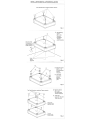
INSTALLATION (Fig. 1 - Fig. 4)
With this series of amplifiers, up to three units can be stacked together in a typical installation.
Depending on the number of units you wish to install, refer to instructions A to C below.
'&CAUTION
• Caution on connection terminals/parts
• Do not allow other objects (particularly electrically conductive) to get too close or in contact with
any of the unit's terminals/parts (power supply, fuse, speaker output terminal, RCA connector,
etc.). Doing so may result in short circuit or accident.
Note:
When stacking amplifiers, do not install horizontally or at an incline. Any installation other than
parallel to the vehicle floor, invalidates the warranty.
Preparation for installation
1.
2.
3.
4.
Using the amplifier as a template, mark the four screw locations.
Make sure there are no objects behind the surface that may become damaged during drilling.
Drill the screw holes.
Position the PDX-5 over the screw holes, and secure with four self-tapping screws.
NOTE:
To securely connect the ground lead, use an already installed screw on the metal part of the vehicle
(marked *). Be sure this is a good ground by checking continuity to the battery (-) terminal. As
much as possible connect all equipment to the same ground point. These procedures will help
eliminate noise.
A. Single unit installation
1. Position the unit over the screw holes you prepared earlier.
2. Remove the four corner top caps on top using the hexagon wrench (large, supplied). Refer to fig.1.
3. Fasten the unit down with the four self-tapping screws (M4 x 40, supplied).Refer to fig.2.
NOTE:
A magnetic screwdriver is recommended to prevent the screw being dropped while tightening.
4. Re-attach the four top caps and hand-tighten.
B. Stack installation of two units
1. Firstly, securely install one unit, as described in steps 1-3 of A above.
2. Attach the four joint caps (supplied with connected amplifier) in the four corners of the first unit
with 2 machine screws (M2.6 x 14, supplied with connected amplifier) per each cap. Refer to fig.3.
3. Stack the second unit on top of the installed unit, aligning the second unit's feet with the joint
caps of the first unit.
4. Remove the four corner top caps of the second unit using the hexagon wrench (Iarge,supplied).
5. Insert the four machine screws (M4 x 36, supplied with connected amplifier) through the top of
the second unit into the four joint caps of the lower unit to connect them together. Refer to fig.4
6. Re-attach the four top caps and hand-tighten.
C. Stack installation of three units
1. Firstly, securely install the first two units firmly as described in steps 1 to 5 of B above.
2. Next, install the third unit as described for the second unit in B above. With this, stack installation
of the 3 units is completed.
INSTALLATION/INSTALLATION/INSTALACION
Top Cap!Capuchon superieurlTapon superior
Fig. 1
CD
Hole! ~=------_---.J.
Trous!
Agujeros
Self-Tapping
Screw
(M4 x 40)!
Vis autotaraudees!
Tornillos
autorroscantes
---j~
Fig. 2
....._-
~~--~=="""'-_
@ Machine Screw
(M2.6 x 14)!
Vis mecanique!
Tornillo
mecanico
@ Joint Cap!
Capuchon
de joint!
Tapon de
junta
Fig.3
Top Cap!Capuchon superieurlTapon superior
@ Machine Screw
(M4 x 36)!
Vis mecanique!
Tornillo mecanico
@ Joint Cap!
Capuchon de joint!
Tapon de junta
Second uniV
Deuxieme unitel
Segunda unidad
First unit!
premiere unite!
Primera unidad
Fig.4
;:
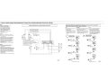
CONNECTIONS (Fig. 5 - Fig. 8)
CONNECTIONS/CONNEXIONS/CONEXIONES
Before making connections. be sure to turn the power off to all
audio components. Connect the yellow battery lead from the amp
directly to the positive (+) terminal of the vehicle's battery. Do not
connect this lead to the fuse block
&
•
o
c""': 0
Fig.S
~~~~~~=O&:§O
Wire Terminal/Borne de conducteurl
Terminal del conductor
Fig. 6
Hexagon screwNis
Tornillo hexagonal
G(
~
.
__
a six pansl
Fig.7
Speaker plug/Prise du haut-parleurfToma del
altavoz
@
Hexagon screw hole/Orifice de la vis
panslAgujero de tornillo hexagonal
@
Negative lead terminal hOle/Orifice de la borne
du conducleur negatillAgujero del terminal del
a six
"C:OJ.~j..n
@
Speaker negative terminal/Borne negative du
haul-parleurfTerminal negativQ del altavoz
®
Speaker wire {negative)/Cable du haut-parleur
(negatil)/Cable de! altavoz (negativo)
®
Positive lead terminal hole/Orifice de la borne
du conducteur positil/Agujero del terminal del
conductor positive
o
2.
Note;
Fully insert the speaker plug to avoid poor connection, or the
wire coming loose due 10 vehicle vibration, etc.
The speaker plug can be connected either way, regardless of
polarity indication
Do not connect speaker leads together or to chassis ground
The speaker ptug is the same shape for both full-range and
monaural connection. Be sure 10 connect the lull range plugs
to the CH·l - CH-4 terminals. and the monaural plug to the
SUB W. terminal.
3.
4
•
Battery Lead (sold separately)
Be sure to add a a fuse as close as possible to the battery's positive (+) terminal. This fuse will protect your vehicle's electrical sys·
tem in case of a short circuit. If you need to extend this lead. only
use AWG4 (the wire gauge) for this connection.
1.
2.
o
Remote Turn-On Lead (sold separately)
Connect this lead to the remote turn-on or power antenna
(positive trigger, (+) 12V only) lead of your head unit.
G
Ground Lead (sold separately)
Connect this lead securely to a clean. bare metal spot on the
vehicle's chassis. Verify this point to be a true ground by checking
for continuity between that point and the negative (-) terminal 01
the vehicle's battery. Ground all your audio components to the
same point on the chassis to prevent ground loops.
Only use AWG4 (the wire gauge) for this connection
Check the wire gauge.
Notes;
Only AWG4 (the wire gauge) is recommended to use for
this connection
o
If in doubt, consult your dealer or Customer Support
regarding correct wire gauge to use
Strip back between 7-10mm (9/32"-318") of the power
wire's insulation to expose the conductor.
Notes;
If the length of the exposed conductor is too short. a poor
connection may occur causing operation failure or sound
interruption.
Conversely. if the exposed conductor is too long. an
electrical short-circuit may occur
Loosen the unil's wire terminal hexagon screws. and
insert the exposed conductor into the terminal and finally
tighten to secure the connection.
Verify lhatthe power wire is connected securely.
Cautions on speaker wire connections
When you connect the speaker wire to the unit, you need to inser.
the speaker wire into the speaker plug. Below explains how to
insert the speaker wire into the speaker plug
o
G)
®
Power Supply Terminal
t.
Fuse
RCA Input Jacks
Connect these lacks to the line out leads on your head unit using
RCA extension cables (sold separately)
Wire/Conducteur/Condctor
condllctor
o
a
e
o
Wire Terminal/Borne de
conducteurlTerminal del
conductor
'jJ
;f------
To prevent external noise from entering the audio system.
Locate the unit and route the leads at least 10 cm (3-15116")
away from the car harness.
Keep the battery power leads as far away from other leads as
possible
Connect the ground lead securely to a bare metal spot
(remove any paint or grease if necessary) of the car chassis.
If you acid an optional noise suppressor, connect it as far away
from the unit as possible. Your Alpine dealer carries various
noise suppressors, contact them for lurther information.
Your Alpine dealer knows best about noise prevention
measures so consult your dealer for further information.
Cautions on Power Wire connections
Note;
Use the supplied hexagon screws forthis connection. It is highly
recommended that this be carried out by the dealer
II you make this connection yourself. ensure the connection is
correct by fOllowing the instructions below carefully.
Be sure to use the supplied hexagon screws for this
connection
For safety reasons, connect the battery wire last
To prevent disconnection of the leads or dropping of the unit.
do nol carry the unit by the wire
Be sure to add a fuse as close as possible to the ballery.
Make sure to use a fuse of the correct rating for the power
wire
Speaker Output Terminals
Referring to "Cautions on speaker wire connections", insert the
speaker wire into the speaker plug, which is Ihen inserted in the
speaker output terminal.
Wire/Conducteur/Conductor 7-10 mm (9/32" -3/8")
~~ \
CAUTION
Caution on connection terminals/parts
Do not allow other objects (particularly electrically
conductive) to get too close or in contact with any of the
unit's terminals/parts (power supply. fuse, speaker output
terminal, RCA connector. etc.). Doing so may result in
short circuit or accident.
•
The power wire cannot be connected until its end has been
stripped. Below explains how to connect the stripped end of the
power wire.
3.
4.
5.
Check the wire gauge
Notes;
The available speaker wire gauge for this unit is AWG8AWG16
o
If in doubt, consult your dealer regarding correct wire
gauge to use
Strip back between 7·10mm (9/32 0 -318 0 ) of the wire's
insulation to expose the conductor.
Notes;
If the length of the exposed conductor is too shore a poor
connection may occur causing operation tailure or sound
interruption.
Conversely, il the exposed conductor is too long, an
electrical short-circuit may occur
Loosen fully the speaker plug's 2 hexagon screws using
the hexagon wrench (small, supplied).
Insert fully the exposed conductor of the speaker wire into
the wire terminal hole. Refer to Fig.8
Note;
Insertlhe speaker wire observing the +/- indications on
the speaker plug. Insert the positive speaker wire into
the positive speaker terminal. and the negative speaker
wire into the negative speaker terminaL
Tighten the 2 hexagon screws using the hexagon wrench
(small, supplied).
Positive speaker terminal/Borne positive du
haul-parleur~erminalpositivo del allavoz
Speaker wire (positive)/Cable du haul-parleur
(posilif)/Cable del altavoz (positivo)
Fig.8
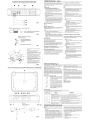
SWITCH SETTINGS (Fig. 9)
To make adjustments 8 - 15 below, remove the hexagon screw
(indicated by in the illustration) using the small, hexagon wrench
(supplied). Remove the control cover.
*
SWITCH SETTINGS/REGLAGES DE COMMUTATEUR/AJUSTES DEL INTERRUPTOR
0, '-D
Input Gain Adjustment Control (CH.112, CH-314)
Set the PDX-5 input gain to the minimum (4V) position. Using a
dynamic CD as a source, increase the head unit volume until the
output distorts. Then, reduce the volume 1 step (or until the output is no longer distorted). Now, increase the amplifier gain until
the sound from the speakers becomes distorted. Reduce the gain
slightly so the sound is no longer distorted to achieve the optimum gain setting.
I·
0,0
Crossover Mode Selector Switch
FILTER
a) ~et to the "LP" position when the amplifier
IS used to drive a subwoofer. The frequen·
cies above the crossover point will be atu..--.tenuated at 12 dB/octave.
~..J,~~
LC
Dr-----
FILTER
~p
FILTER
~~p
b) Set to the "HP" position when the amplifier
is used to drive a tweeter/midrange system. The frequencies below the crossover
point will be attenuated at 12 dB/octave
e, tV Crossover Frequency Adjustment Knob
Permits the adjustment of the crossover frequency. Rotate the
knob to select any frequency between 30 and 400 Hz as the cross·
over point.
o Input Gain Adjustment Control (SUB W.)
Set the PDX·5 input gain to the minimum position. Using a dynamic CD as a source. increase the head unit volume until the
output distorts. Then. reduce Ihe volume t step (or until the output is no longer distorted). Now. increase the amplifier gain unlil
the sound from the speakers becomes distorted. Reduce the gain
slightly so the sound is no longer distorted to achieve the opUmum gain selling
6' Crossover Frequency Adjustment Knob (LP FILTER)
Permits the adiustment of the crossover frequency. Rotate the
knob to select any frequency between 50 and 200 Hz as the crossover point.
$.~ Power Indicator
Lights up when power is on
Is off when power is off
c) Set to the "OFF" position when the amplifier will be used fordriving fUll-range speakers. The full Irequency bandwidth will be
output to the speakers with no high or low
frequency attenuation.
U) Status Indicator
Lights up when power is on. You can confirm the amplifier status by how the indicator
is lit. as shown in the table below. Turn off when power is off.
Indicator status
Blue
Red
Solution
Status
Amplifier circuit is normal.
Amplifier circuit is abnormal. An Remove the battery cable and eliminate the cause. Then turn on the
electrical short has occurred, or unit and verify thaI the indicator color has changed 10 blue. If it
supply current is too high.
remains red, turn off the unit and consult your dealer.
Batlery voltage is too high
Find the cause of the excessive voltage. Eliminate the cause and the
indicator color changes to blue
Ambient temperature is too high Decrease the vehicle's interior temperature to a normal level. The
indicator color changes to blue.
Blinking
PDX-5
0-+--1
I
®
_ _ ..J
®
~®
(j)
®
@
Fig.10
@
Decrease the vehicle's interior temperature to a normal level. Output
protection is released and the indicator color changes to blue
CONNECTION CHECK LIST (Fig.l0)
,
eD
Output protection (due to high
temperature) is activated.
Please check your head unit for the conditions listed below:
(Fig. 10)
a. The head unit does not have a remote tum-on or power antenna lead
b The head unit's power antenna lead is activated only when
the radio is on (turns off in the tape or CD Mode).
c. The head Ilnifs powAr ~ntenna lead is logic level output (...)
5V. negative trigger (grounding type), or cannot sustain (+)
12V when connected to other equipment in addition to the
vehicle's power antenna. 1/ any of the above conditions exist,
the remote turn-on lead of your PDX·5 must be connected to
a switched power source (ignition) in the vehicle. Be sure to
use a 3A fuse as close as possible to this ignition tap. Using
this connection method. the PDX-5 will turn on and stay on as
long as the ignition switch is on
If this is objectionable. a SPST (Single Pole, Single Throw) switch,
in addition to the 3A fuse mentioned above, may be installed inline on the PDX-5 turn-on lead. This switch will then be used to
turn on (and off) the PDX-5. Therefore. the switch should be
mounted so that is accessible by the driver. Make sure the switch
is turned off when the vehicle is not running. Otherwise, the amplifier wil! remain nn And drilin the l)iltlerv.
ill Remote Turn-On Lead
® Power Antenna
@ Remote Turn-On Lead
@ To other Alpine components' Remote Turn·On Leads
@ SPST Switch (optional)
® Fuse(3A)
(f) As close as possible to the vehicle's ignition tap
® Ignition Source
TYPICAL SYSTEM CONNECTIONS/CONNEXIONS TYPIQUES DU SYSTEME/CONEXIONES TIPICAS DEL SISTEMA
[English]
o
o
o
fIt
o
f!l
fll
Battery lead (sold separately)
Remote Turn-on Lead (sold separately)
Important Tips on Bridging an Amplifier/Conseils importants lors de la mise en pont d'un ampliflcateurl
Consejos importantes cuando conecte en puente un amplificador
5 Speaker System/Systeme de 5 haut-parleurs/Sistema de 5 altavoces
Ground Lead (sold separately)
Front Left Speaker (sold separately)
Front Right Speaker (sold separately)
NOTE:
The following problems may occur when
not properly connected
1) If only one input per channel is used,
low output results.
2) Using only one input per channel may
cause overheating. This could result
in prematurely triggering overheating
protection.
Rear Left Speaker (sold separately)
Rear RighI Speaker (sold separately)
m SubwQofer (sold separately)
f.D
ACA Extension Cable (sold separately)
@> Head Unit. etc.
€El
V-Adaptor (sold separately)
REMARQUE:
Les problemes suivants peuvenl se produire
quand il n'est pas correctement relie
1) L'utilisation d'une seule entree par canal
reduitle niveau de sortie
2) L'utilisation d'une seule enlree par canal
peut provoquer une surchaulle. Celle-ci peut
entrainer un declenchement premature de
la protection de surchauffe
[Franlfsisj
o
o
G
fIt
tD
Conducteur de la batterie (vendu separement)
Conducleur de mise SQUS tension teh3commandee
(vendu separemenl)
O
Conducteur de mise a la terre (vendu separement)
Haut-parleur avant gauche (vendu separement)
Haut-parleur avant droit (vendu separement)
fIl
€il
Cable d'extension RCA (vendu separement)
[Espanal]
Cable de la bateria (vendido separadamente)
Cable para encendido remoto (vendido
separadamente)
G Cable de tierra (vendido separadamente)
fIt Altavoz delantero izquierdo (vendido separadamente)
f) Altavoz delantero derecho (vendido separadamente)
@l Altavoz trasero izquierdo (vendido separadamente)
fIl Altavoz trasero derecho (vendido separadamente)
@) Altavoz de sUbgraves (vendido separadamente)
flil Prolongador electrico RCA (vendido separadamente)
fD Toma del al1avoz
@l Unidad principal, etc.
@) Adaptador en forma de "Y· (vendido separadamente)
43
o
CO Head unit (sold separately, CDA-9387 etc.)!
Unite principale CO (vendu separement, CDA-9887 etc.)!
Unidad principal de CD (vendido per 5eparado, CDA-9887 etc,)
Sub~feroutputle(mioall
(L) ~ ~ (Rl
:::~~::::::::,':::=;:Xl..
1 (Ai
•
~ ~
'
• , '
"
(POX 5)
tD
f&
IR}
0
i.0...
8
~ M~IIID
.
l·J,:L::!::::::::lL::::::::::::::::::::::::=..T
!..l..l.
:.. c
..lL
:.,
¥~
IJ:::::::::::::=::=:::=:::::::::~::::)i.......................¥
Improper connection!
Connexion incorrectel
Conexi6n Incorrects
iiD
. . 1~
_- _ _
~
~
IA}
{L}
~mm:J
U
C£JC~oY~
iL}
blg[)
IRI
~
~~~
(LI
~mt©
:
~~J)~
ill
~",.[D
~'
Fig.11
x
c:u-c:~~
~~.,;t'~
ill
Haut-parleur arriere droit (vendu separement)
@l Unite principale, etc
f!) Adaptateur en torme de "Y " (vendu separement)
Con.,IOn co"ecl,
IRI
@l Haut-parleur arriere gauche (vendu separement)
@) Haut-parleur de sous-graves (vendu separement)
Proper connectionl
Connexion correctel
NOTA:
Podrian surgir los siguientes problemas si la
conexi6n no se realiza correctamente.
1) Si solamente sa utiliza una entrada por
canal, la potencia obtenida sera baja
2) Si solamente se utiliza una entrada por
canal, la unidad podria sobrecalentarse.
Como resultado, podria activarse antes
de tiempo el dispositivo de protecei6n
frente a sobrecalentamiento.
>Itlc;.~m
~~!¥ .
,
~~J)~
IL}
{OnesignallUnsignallUnasenalj
IRI~~
cue
ILl
(One signal I Un signal I Una senal)
Fig. 12
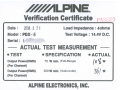
~LPlNEe
Verification Certificate
2008. 3. 21
Date :
Model : PDX- 5
Serial:
Load Impedance : 40hms
Test Voltage : 14.4V D.C.
L
ACTUAL TEST MEASUREMENT
• TEST
• SPECIFICATION
Output Power(RMS)
(Per Channel)
75 W min. (Full-Range)
Output Power(RMS)
(Per Channel)
300 W min. (Subwoofer)
• ACTUAL
ALPINE ELECTRONICS, INC.
(
0 if>
W
I
W
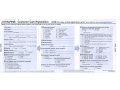
.#/#"ALPINE. Customer Care Registration
.... For easy on-line registration, go to ..www.alpine-usa.com/registration ..
Thank you for choosing Alpine! Please register your product with us so we can serve you better.
First name:
_
Last name:
1. 0 Cassette Player
2.0 CD Player
3. 0 MD Player
4. 0 DVD Player
5. 0 CD Changer
6. 0 Amplifier
7. 0 Speaker
8. 0 Subwoofer
Home address: =St-re~et-ad~dr-es-s-----------
City
State/Provo
Zip Code
May we contact you at this address? 1.0 Yes 2.0 No
Phone number: (
--------------May we contact you at this number?
UJ
a:
UJ
::I:
...J
«
UJ
(J)
E-mail Address:
May we contact you bye-mail?
Gender
1.0 Yes 2.0 No
-----------==------;=--
1.0 Male
2.0 Female
• Date of Birth Month:
Marital Status
1.0Yes 2.0 No
Year:
1.0 Single
=---2.0 Married
Which ethnicity best describes yourself:
1. 0 Caucasian
2.0 Hispanic
3. 0 African-American
4. 0 Asian
5.0 Other
_
c)
9. 0 Monitor Controller
10.0 Video Monitor
11 . 0 Navigation
12.0 Mobile Mayday
13.0 Video Tape Player
14.0 Processor/Equalizer
15.0 Security
16.0 Other
1.0Yes
J,
_
• Serial Number:
_
• Date of Purchase:
2.0 Other
--7
--7
(Model No.)
_
(Brand Name)
_
--7
1.0 Factory installed
2.0 Alpine
3.00ther
Have you purchased Alpine products before?
Thank you for your cooperation! We value your privacy. This information will remain confidential with Alpine and its affiliates.
Secretarial/Clerical
Sales
General Labor
Professional
1.8 Less than $30,000
2.
$30,000 - $50,000
3.0 $50,000 - $70,000
*Previous brand replaced?
1. 0 First time
2.
3.
4.
5. 0
6. 0 Engineering!Technical
7. 0 Farming/Fishing
8.8 Retired
9.
Student
10.0 Other'
_
(J)
m
»
r::I:
m
m
:c
Household Income
• Purpose of buying this unit?
1. 0 Addition
2.0 Replacement
1. 0 I usually have more electronic equipment than my friends
2.0 I am usually one of the first of my friends to buy the newest
electronic equipment
3. 0 I usually wait until a product has been out for a while before
I purchase it
4. 0 I am usually on of the first of my friends to know about the
newest car
5. 0 I usually know more about cars than my friends
Occupation
1. ~ Executive/Managerial
Year:
If navigation system, which monitor?
1.0 Alpine
_
Which of the following statements best describes you?
_
Month:
2.0No.
(Brand Name)
Model Number:
Your highest level of education completed:
1. 0 High School Student
2.0 High School Graduate
3.02 Yr. Degree/Some College
4.0 Completed 4 Yr. College
5. 0 Completed Graduate School
When you purchased this Alpine unit, did you
compare it with other brands?
Product purchased
_
2. 0 Two or more times
4.0 $70,000 - $90,000
5.0 $90,000 - $110,000
6.0 Over $110,000
Type of vehicle in which this unit is installed.
_
Make:
Purchased Year:
Model:
_
_
Model Year:
_
How was this vehicle purchased?
1. 0 Bought
Customer Care Registration is for Product registration.
Failure to complete and return this card does not diminish your warranty rights.
2. 0 Leased
PART NO. 68P04190K17-A
M3544084010
II I I II
NO POSTAGE
NECESSARY
IF MAILED
IN THE
UNITED STATES
BUSINESS REPLY MAIL
FIRST-CLASS MAIL
PERMIT NO. 320
TORRANCE CA
POSTAGE WILL BE PAID BY ADDRESSEE
ATTENTION MARKETING SERVICES
ALPINE ELECTRONICS OF AMERICA INC
PO BOX 2859
TORRANCE CA 90509-9939
11,1,,11,",1,1,11",1,1,,1,1,,1,1,,"11,1,1"1",11
i
FOR USE IN USA, PLEASE FOLD HERE AND ENSURE THAT
AMERICAN ADDRESS FACES UP,
'dn S38'v':l SS3tlOO'v' N'v'IO'v'N'v'8
1'v'H13tlnSN3 ON'v' 3tl3H OlO:l 3S'v'31d "v'O'v'N'v'8 NI 3Sn tlO:l
1
1'1'1"'11'1"'1'1"1"1'111'""'11'1'1""11"1'11
VJI~3VIJ''if
::10 S31V1S 0311Nn
VJ 3JNV~~01
ld AJ~3VIJV~8 917~6~
SJINO~lJ313 3NldlV
9LB6-~0906
BSIJIm AI lid II TIIl1IV1...
m.lII&I
UAVd lSNOdlBlllVW AldlB SSl.sna lVNon¥NBUM
-
AIVSUIJl
1IV1... 1II
..
HE lIN IUIISI111
DmSDIM
11101
IJMI:I
-.
II
II
~
II
ffDY/iLPINEA
GARANTIE L1MITEE
Fideles a leur engagement de ne fournir que des produits de qualite, ALPINE ELECTRONIQUE DE L'AMERIQUE, INC. et
ALPINE ELECTRONIQUE DU CANADA, INC, (Alpine) sont heureuses de vaus offrir cette garantie, Nous vous suggerons de Ie
lire attentivement et en entier. Si va us avez la maindre question, veuillez contacter I'un de nos concessionnaires ou appeler
directement Alpine aux numeros listes ci-dessous.
.PRODUITS COUVERTS PAR LA GARANTIE
@ Vous devez donner une description detaillee des
Cette garantie couvre les produits audio de voiture et les
accessoires connexes ("Ie produit"). Elle ne couvre les
produits que dans Ie pays ou ils ont ete achetes.
Cette garantie est en vigueur pendant un an a partir de la date
du premier achat du client.
problemes qui sont a I'origine de votre deman de de
reparation.
@ Vous devez joindre la preuve de votre achat du produit.
(4) Vous devez emballer soigneusement Ie produit pour eviter
tout dommage durant son transport. Pour eviter la perte
de I'envoi, il est conseille de choisir un transporteur qui
propose un service de suivi des envois .
• PERSONNES PROTEGEES PAR LA GARANTIE
.L1MITATION DES GARANTIES TACITES
Seul I'acheteur original du produit. s'il resisde aux Etats-Unis,
a Porto Rico ou au Canada, peut se prevaloir de la garantie.
LA DUREE DE TOUTES LES GARANTIES TACITES, Y
COMPRIS LA GARANTIE D'ADAPTATION A L'UTILISATION
ET LA GARANTIE DE QUALITE LOYALE ET MARCHANDE,
EST L1MITEE A CELLE DE LA GARANTIE EXPRESSE
DETERMINEE CI-DESSUS. PERSONNE N'EST AUTORISE
AENGAGER AUTREMENT LA RESPONSABILITE D'ALPINE
EN VERTU DE LA VENTE D'UN PRODUIT
.DUREE DE LA GARANTIE
.CE QUI EST COUVERT
Cette garantie couvre tous les defauts de materiaux et de
fabrication (pieces et main d'ceuvre) du produit.
.CE QUI N'EST PAS COUVERT
Cette garantie ne couvre pas ce qui suit:
Les dommages survenus durant Ie transport des produits
renvoyes a Alpine pour etre repares (Ies reclamations
doivent etre adressees au transporteur);
(?) Les degats provoques par un accident ou une mauvaise
utilisation, y compris des bobines acoustiques grillees
suite a une surexcitation des enceintes (augmentation
du niveau de I'amplificateur jusqu'a atteindre un effet de
distorsion ou d'ecretage), une defaillance mecanique
des enceintes (perforations. dechirures ou fentes),
panneaux LCD fissures ou endommages, disques durs
endommaqes ou ayant subi une chute.
(3) Tout degat provoque par negligence. usage inapproprie,
mauvaise utilisation ou par Ie non-respect des
instructions indiquees dans Ie manuel de I'utilisateur.
@ Les dommages dus a la force majeure, notamment aux
tremblements de terre, au feu, aux inondations, aux
tempetes ou aux autres cataclysmes naturels;
Les frais ou les depenses relatifs a I'enlevement ou a la
reinstallation du produit;
(5) Les services rendus par une personne, physique ou
morale nan autorisee;
® Les produits dont Ie numero de serie a ete efface, modifie
ou retire;
(7) Les produits qui ont ete adaptes ou modifies sans Ie
consentement d'Alpine;
@ Les produits qui ne sont pas distribues par Alpine aux
Etats-Unis, a Porto Rico ou au Canada;
@ Les produits qui n'ont pas ete achetes par I'entremise d'un
concessionnaire Alpine autorise;
',f
.COMMENT SE PREVALOIR DE LA GARANTIE
CD
II vous faut remettre Ie produit necessitant des reparations
a un centre de service autorise Alpine ou a Alpine meme et
en assumer les frais de transport. Alpine a Ie choix entre
reparer Ie produit ou Ie remplacer par un produit neuf ou
revise, Ie tout sans frais pour vous. Si les reparations sont
couvertes par la garantie et si Ie produit a ete envoye a un
centre de service Alpine ou a Alpine, Ie paiement des frais
de reexpedition du produit incombe Alpine,
.EXCLUSIONS DE LA GARANTIE
ALPINE STIPULE EXPRESSEMENT QU'ELLE N'EST PAS
RESPONSABLE DES DOMMAGES-INTERETS ET
DOMMAGES INDIRECTS PROVOQUES PAR LE PRODUIT
LES DOMMAGES-INTERETS SONT LES FRAIS DE
TRANSPORT DU PRODUIT VERS UN CENTRE DE
SERVICE ALPINE, LA PERTE DE TEMPS DE L'ACHETEUR
ORIGINAL, LA PERTE D'UTILISATION DU PRODUIT, LES
BILLETS D'AUTOBUS, LA LOCATION DE VOITURES ET
TOUS LES AUTRES FRAIS LIES A LA GARDE DU
PRODUIT.
LES DOMMAGES INDIRECTS SO NT LES FRAIS DE
REPARATION OU DE REMPLACEMENT D'AUTRES BIENS
ENDOMMAGES SUITE AU MAUVAIS FONCTIONNEMENT
DU PRODUIT
LES RECOURS PREVUS PAR LES PRESENTES
EXCLUENT ET REMPLACENT TOUTE AUTRE FORME DE
RECOURS
ellEN ENTRE LA GARANTIE ET LA LOI
La garantie vous donne des droits specifiques, mais vous
pouvez aussi jouir d'autres droits, qui varient d'un etat ou
d'une province a I'autre. En outre, certains etats et certaines
provinces interdisent de limiter la duree des garanties tacites
ou d'exclure les dommages accessoires ou indirects. Dans ce
cas, les limites et les exclusions de la garantie peuvent ne pas
s'appliquer a vous.
.CLAUSE APPLICABLE AU CANADA SEULEMENT
Pour que la garantie soit valable. II faut qU'un centre
d'installation autorise ait installe Ie systeme audio pour I'auto
dans votre vehicule et qu'il ait ensuite appose son cachet sur
la garantie.
.NUMEROS D'APPEL DU SERVICE
A LA CLIENTELE
Si vous avez besoin de nos services, veuillez appeler Alpine
aux numeros ci-dessous pour Ie centre de service autorise
Alpine Ie plus proche.
AUDIO DE VOITURE
NAVIGATION
1-800-ALPINE-1 (1-800-257-4631)
1-888-NAV-HELP (1-888-628-4357)
Ou visitez notre site Web a I'adresse httpJ/www.alpine-usa.com
ALPINE ELECTRONIOUE DE L'AMERIOUE, INC., 19145 Gramercy Place, Torrance, California 90501, USA
ALPINE ELECTRONIOUE DU CANADA, INC., 777 Supertest Road, Toronto, Ontario M3J 2M9, Canada
N'envoyez aucun produit aces adresses.
Appelez notre numero gratuit ou visitez notre site Web si vous recherchez un centre de service.
~/iLPINER
LIMITED WARRANTY
ALPINE ELECTRONICS OF AMERICA, INC. AND ALPINE OF CANADA INC. ("Alpine"), are dedicated to quality
craftsmanship and are pleased to offer this Warranty. We suggest that you read it thoroughly. Should you have any
questions, please contact your Dealer or contact Alpine at one of the telephone numbers listed below.
• PRODUCTS COVERED:
This Warranty covers Car Audio Products and Related
Accessories ("the product"). Products purchased in the
Canada are covered only in the Canada. Products
purchased in the USA are covered only in the U.S.A.
@ You must supply proof of your purchase of the product.
@ You must package the product securely to avoid
damage during shipment. To prevent lost packages it is
recommended to use a carrier that provides a tracking
service.
.LENGTH OF WARRANTY:
.HOW WE LIMIT IMPLIED WARRANTIES:
This Warranty is in effect for one year from the date of the
first consumer purchase.
This Warranty only covers the original purchaser of the
product, who must reside in the United States, Puerto Rico
or Canada.
ANY IMPLIED WARRANTIES INCLUDING FITNESS FOR
USE AND MERCHANTABILITY ARE LIMITED IN
DURATION TO THE PERIOD OF THE EXPRESS
WARRANTY SET FORTH ABOVE AND NO PERSON IS
AUTHORIZED TO ASSUME FOR ALPINE ANY OTHER
LIABILITY IN CONNECTION WITH THE SALE OF THE
PRODUCT.
• WHAT IS COVERED:
.HOW WE EXCLUDE CERTAIN DAMAGES:
This Warranty covers defects in materials or workmanship
(parts and labor) in the product.
ALPINE EXPRESSLY DISCLAIMS LIABILITY FOR
INCIDENTAL AND CONSEQUENTIAL DAMAGES
CAUSED BY THE PRODUCT. THE TERM "INCIDENTAL
DAMAGES" REFERS TO EXPENSES OF
TRANSPORTING THE PRODUCT TO THE ALPINE
SERVICE CENTER, LOSS OF THE ORIGINAL
PURCHASER'S TIME, LOSS OF THE USE OF THE
PRODUCT, BUS FARES, CAR RENTALS OR OTHERS
COSTS RELATING TO THE CARE AND CUSTODY OF
THE PRODUCT. THE TERM "CONSEQUENTIAL
DAMAGES" REFERS TO THE COST OF REPAIRING OR
REPLACING OTHER PROPERTY WHICH IS DAMAGED
WHEN THIS PRODUCT DOES NOT WORK PROPERLY.
THE REMEDIES PROVIDED UNDER THIS WARRANTY
ARE EXCLUSIVE AND IN LIEU OF ALL OTHERS.
.WHO IS COVERED:
.WHAT IS NOT COVERED:
This Warranty does not cover the following:
Damage occurring during shipment of the product to
Alpine for repair (claims must be presented to the
carrier).
1.2; Damage caused by accident or abuse, including burned
voice coils caused by over-driving the speaker (amplifier
level is turned up and driven into distortion or clipping).
Speaker mechanical failure (e.g. punctures, tears or
rips). Cracked or damaged LCD panels. Dropped or
damaged hard drives.
(3) Damage caused by negligence, misuse, improper
operation or failure to follow instructions contained in the
Owner's manual.
(~) Damage caused by act of God, including without
limitation, earthquake, fire, flood, storms or other acts of
nature.
Any cost or expense related to the removal or
reinstallation of the product.
(5) Service performed by an unauthorized person, company
or association.
iii) Any product which has the serial number defaced,
altered or removed.
(7) Any product which has been adjusted, altered or
modified without Alpine's consent.
(,13) Any product not distributed by Alpine within the United
States, Puerto Rico or Canada.
(§) Any product not purchased from an Authorized Alpine
Dealer.
(,1)
.HOW STATE/PROVINCIAL LAW RELATES TO THE
WARRANTY:
This Warranty gives you specific legal rights, and you may
also have other rights which vary from state to state and
province to province. In addition, some states/provinces do
not allow limitations on how long an implied warranty lasts,
and some do not allow the exclusion or limitation of
incidental or consequential damages. Accordingly,
limitations as to these matters contained herein may not
apply to you.
.IN CANADA ONLY:
This Warranty is not valid unless your Alpine car audio
product has been installed in your vehicle by an Authorized
Installation Center. and this warranty stamped upon
installation by the installation center.
.HOW TO OBTAIN WARRANTY SERVICE:
• HOW TO CONTACT CUSTOMER SERVICE:
CD
Should the product require service, please call the follOWing
number for your nearest Authorized Alpine Service Center.
You are responsible for delivery of the product to an
Authorized Alpine Service Center or Alpine for repair
and for payment of any initial shipping charges. Alpine
will, at its option, repair or replace the product with a
new or reconditioned product without charge. If the
repairs are covered by the warranty, and if the product
was shipped to an Authorized Alpine Service Center or
Alpine, Alpine will pay the return shipping charges.
@ You should prOVide a detailed description of the
problem(s) for which service is required.
CAR AUDIO 1-800-ALPINE-1 (1-800-257-4631)
NAVIGATION 1-888-NAV-H ELP (1-888-628-4357)
Or visit our website at; http://www.alpine-usa.com
ALPINE ELECTRONICS OF AMERICA, INC., 19145 Gramercy Place, Torrance, California 90501, USA
ALPINE ELECTRONICS OF CANADA, INC., 777 Supertest Road, Toronto, Ontario M3J 2M9, Canada
Do not send products to these addresses.
Call the toll free telephone number or visit the website to locate a service center.
68-00493Z72-A (Y)
M3544091010