1
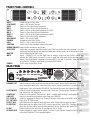
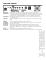
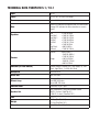
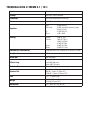
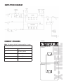
OFFICIAL WARWICK
AMP OWNER MANUAL
ENGLISH
SAFETY HINTS
- Read these instructions
- Keep these instructions
- Heed all warnings
- Follow these instructions
Caution: To reduce the risk of electrical shock, do
not remove the cover. Or expose this appliance to
rain or moisture. No user serviceable parts inside; refer serving to qualified personnel.
Apparatus shall not be exposed to dripping or
splashing and no objects filled with liquids, such
as vases shall be placed on the apparatus.
ENGLISH
This symbol, wherever it appears, alerts you to
the presence of uninsulated dangerous voltage
inside the enclosure - voltage that may be sufficient to constitute risk of shock.
!
This symbol, wherever it appears, alerts you to
important operating and maintenance instructions in the accompanying literature. Read the
manual.
Use only with cart, stand, tripod, bracket or table
specified by the manufacture, or cart/apparatus
combination to avoid injury from tip-over.
Congratulations on the purchase of the new Warwick amplifier head. Please read through these
instructions before connecting and operating the device. If you keep to the guidelines set out in this
manual, you will soon be able to appreciate the quality of this new Warwick amplifier. Please keep this
instruction booklet handy in case you need to consult it again. Please send the PASSPORT to the
address indicated therein.
RECOMMENDATIONS
The following recommendations are designed to ensure that the device always functions reliably:
• Never open the casing! To do so would expose you to the risk of an electric shock. Should repairs prove necessary, leave
them to qualified service personnel.
• Avoid dust and high moisture levels, direct sunlight and extremely high or low temperature.
• Safeguard the device from excessive vibration. Always place the unit on a stable and horizontal surface.
• See to adequate ventilation. The device should not be placed on soft surfaces (carpet, cushions, etc.). When mounting
it in a rack, make sure that the rear and lateral cooling vents remain unobstructed.
• Avoid leaving the unit near radiators or other objects producing heat.
• Internal components should only be adjusted or cleaned by qualified service technicians. Ensure no object or liquid
penetrates the device through its cooling vents.
• When replacing a fuse make sure you fit in one of identical value!
HINTS
ENGLISH
Have the device examined by a qualified service technician in the following cases:
• the mains lead or mains switch have been damaged,
• objects or liquids have penetrated the device,
• it has been exposed to excessive moisture,
• malfunctions or abnormal operating conditions have occurred,
• the device has been dropped or the casing damaged.
- This apparatus shall not be exposed dripping or splashing and that no objects filled with liquids, such as vases, shall
be placed on the apparatus.
- This apparatus should be connected to a MAINS socket outlet with a protective earthing connection.
- Mains plug or appliance connector shall be used as the disconnect device, so mains plug or appliance connector should
always remain readily opearable.
- If the apparatus shows any malfunction, immediately disconnect the main power cord from the mains socket.
- Do only operate effects pedals in-between the instrument and the amplifier, as these devices are not designed for the
supplied load of an effects loop.
- Remove the plug whenever changing a fuse.
- Only ever replace a fuse with another of the same type. Never bridge defective fuses.
- Make sure the top and bottom of the device are properly ventilated and that the vents are not blocked.
- Do not subject the device to excessive vibration or hard jolts as these could damage the device.
- Don't undertake repairs yourself.
- Only allow the case to be opened by qualified personnel. (Remove the plug).
- Repairs should only be undertaken by qualified personnel.
SHOULD YOU FIND YOURSELF ONE DAY WONDERING: "WHY IS THERE NO SOUND COMING OUT?"
please check:
- all stub cables,
- all connections of these cables
and proceed anew by following the guidelines of the chapter GETTING STARTED. Possibly the problem reveals to be an
operational error.
PROTECTIVE CIRCUITS
Your new Warwick amplifier is equipped with a series of circuits to prevent it from destruction in case of inadequate operating conditions:
Power-up delay:
When the unit is switched on, the SPEAKER OUT sockets are activated with a slight delay to
protect the loudspeakers.
Short-circuit:
In the event of a short-circuit at the power amp outputs, this feature prevents the output stage
transistors from destruction by quickly reducing current.
Direct current (DC): This circuit continuously monitors the power amp output for direct current and protects the loud
speakers from overload should a transistor burn out.
HF oscillation:
Excessive
temperatures:
Note:
By switching the power amp off, this safety feature prevents from damages that could be caused
by frequencies in excess of 20 kHz (feedback, etc.).
Should the temperature-regulated fan cooler prove to be insufficient in extreme conditions, this
circuit protects the output stage transistors from destruction by switching the device off.
Note: You can recognise that one of these circuits has been activated as a result of a fault, when
the MUTE LED glows continuously even though you have not selected the MUTE mode. In case
of a shortcircuit please check the speaker cable. The amplifier must then be switched off and on
again, to get back into playing mode after having removed the short-circuit. In any other situati
on the amplifier switches automaticallyback to playing mode as soon as it detects the fault has
disappeared (e.g. the amplifier has overheated and cooled down again).
ENGLSIH
GETTING STARTED
1. Make sure that loudspeakers capable of sustaining the load of a bass signal are connected to the SPEAKER OUT
sockets (the speaker cables should meet a cross-section of at least 2 x 1.5 mm).
2. Check that the mains supply has been plugged in and that all external (effects) units possibly used are correctly connected and operational.
3. Set the MASTER control to zero.
4. Plug your bass guitar into the amplifier's INPUT with a shielded line-cable.
5. Press the POWER switch to turn the device on.
6. The tubes need a few minutes until they have reached their optimal operating temperature (TubaPath).
7. Switch MUTE off and the red LED will extinguish.
8. Turn all volume controls of your bass guitar on to their maximum.
9. Adjust the GAIN control until the (loudly) played bass signal flashes the Clip LED (X-Treme).
10 Set the MASTER control to the volume you wish to play at.
11. Adjust the sound that you wish with the controls and switches described in the respective chapters FRONT PANEL
CONTROLS.
12. If necessary readjust GAIN setting. The Tube Sat LED indicates the saturation of the tubes, which will produce a more
compressed and overdriven sound (TubePath).
FRONT PANEL CONTROLS
6
4
2
10
0
6
6
TUBE
SAT
8
4
4
8
2
0
12
GAIN
12
10
0
ROUGH/
SMOOTH
CONTOUR
8
2
10
2ND STAGE
TUBEPATH 5.1
12
MUTE
MASTER
POWER
500 WATTS TUBE DRIVEN BASS AMPLIFIER
6
6
4
8
2
MASTER
MUTE
POWER
FOOTSWITCH
TUNER OUT
LINE OUT
EFF. SEND &
EFF. RETURN
EFFECT MIX
DI PRE/POST
DI OUT
SPEAKER OUT
2
10
0
SHIFT
SHIFT
2
4
6
12
MID 1
2
4
6
MID 2
2
4
4
6
6
TREBLE
HI
BOOST
PHONES
Socket to plug in a bass guitar.
Switch + LED to boost low end.
Control to Cut or Boost deep frequencies.
Control to Cut or Boost low-mid frequencies
Switch + LED to set the operating frequency of MID 1
Control to Cut or Boost high-mid frequencies
Switch + LED to set the operating frequency of MID 2
Control to Cut or Boost high frequencies.
Switch + LED to boost treble.
Headphone socket (min 200 Ω)
Control + LEDs to adjust the input level.
Control boosts lows and highs, while cutting mids.
Switch to alter the timbre of the contour.
Switch adds one output stage tube into the circuit. This feature offers the choice between a so called
hybrid amplifier (tube preamp with transistor power amp) and the sound of an all tube amplifier head.
Control determines the mains level.
Switch + ON/MUTE LED cuts the signal from all outputs, except from the PHONES socket, and
activates the TUNER output (rear panel). In case of signal flow at the power section (Input or Effects
Return), there might appear a popping noise when MUTE is pressed. To avoid this, mute your strings
or have effects like delays muted when pressing the MUTE button.
On/Off switch for the Mains Power.
REAR PANEL
MAINS IN AC
GROUND LIFT
12
BASS
8
2
0
TUBEPATH
INPUT
LOW BOOST
BASS
MID 1
SHIFT 1
MID 2
SHIFT 2
TREBLE
HIGH BOOST
PHONES
GAIN
CONTOUR
ROUGH/SMOOTH
2ND STAGE
LO
BOOST
4
10
0
INPUT
0
AC Terminal with integrated fuse compartment for connection to the mains power supply.
Switch isolates the earth connection from the ground of signal. Should several devices be simultaneously connected to earth by the same conductor as well as via line connections, a so called hum loop
might appear. In this case operate GROUND LIFT to eliminate the current hum (when pressed).
Socket to connect a double latch footswitch with a stereo jack. The tip switches Contour on/off, the
ring switches the 2nd Stage on/off.
Socket for a tuning device. The pure bass signal is available when the amp is switched MUTE.
Output for connection to an external power stage (post MASTER)
Sockets to implement the effects loop. Connects the input of the effects to the SEND socket and its
output to the RETURN socket.
control determine the degree to which the effects within the parallel loop affect the signal.
When depressed, the signal at the DI OUT socket is the pure bass signal (PRE). Otherwise it is the
signal after the tone controls and any connected effects devices have done their work (POST).
Balanced output for the connection to a mixing desk (PA or Studio).
Sockets designed to supply speaker cabinets. Lockable Coaxial Speaker Connection and 1/4" jack
socket (only TubePath 5.1) are connected parallel.
FRONT PANEL CONTROLS
INPUT
GAIN
-10 dB PAD
COMPRESSOR
COMPRESSION
BOOST
EQ ON
EQ BALANCE
socket to plug in a bass guitar.
control + CLIP LED to adjust the input level*.
switch to set the range of the GAIN control. Use it with high output basses.
switch + 2-colored ON/COMPRESS LED to compress the signal.
In position up the compressor is on, in middle position off, in down position it is
on if the EQ section is activated.
control to set the compression ratio.
switch to activate a second volume level. In down position +2dB, in up position
+6dB, in middle poistion the boost is off. Activating the BOOST does automatic
ally activate the Compressor.*
switch activates the EQ section*.
control to balance the volume level with EQ on and EQ off.*
VOICING SECTION:*
BOTTOM
X-TREME
CONTOUR
GROWL
ATTACK
control to extend the low frequency range. Use this at lower volume settings or for
ultra low sounds. At higher volumes it might be better to reduce the low range.
control boosts lows and highs, while cutting mids.
control for boosting/cutting low mids.
control for boosting/cutting presence.
EQ SECTION:*
BASS
MID FREQ.
MID LEVEL
TREBLE
control to boost/cut deep frequencies.
control to determine a frequency.
control to boost/cut the frequency adjusted with the MID FREQ. control.
control to boost/cut high frequencies.
MUTE
switch + ON/MUTE LED cuts the signal from all outputs, except from the PHONES
socket, and activates the TUNER output (rear panel). In case of signal flow at the
power section (Input or Effects Return), there might appear a popping noise when
MUTE is switched. To avoid this, mute your strings and have effects like delays
muted when switching MUTE.
control determines the mains level.
socket for connecting a headphone (min 200 Ω)
on/off switch for the Mains Power.
MASTER
PHONES
POWER
* Note: after adjusting the voicing section, the BOOST or activating the EQ section the Gain control needs to be adjusted that the level is under the
CLIP point.
REAR PANEL CONTROLS
115 V ~ 15 A
230 V~ 8 A
MAINS IN AC
GROUND LIFT
FOOTSWITCH
TUNER OUT
LINE OUT
EFF. SEND &
EFF. RETURN
EFFECT MIX
DI PRE/POST
DI OUT
SPEAKER OUT
AC Terminal with integrated fuse compartment for connection to the mains power supply.
Switch isolates the earth connection from the ground of signal. Should several devices be simultaneously connected to earth by the same conductor as well as via line connections, a so called hum loop
might appear. In this case operate GROUND LIFT to eliminate the current hum (when pressed).
Socket to connect a double latch footswitch with a stereo jack. The tip switches Boost on/off, the
ring switches the EQ on/off.
Socket for a tuning device. The pure bass signal is available at this socket when the amp is switched
MUTE.
Output for connection to an external power stage (post MASTER)
Sockets to implement the effects loop. Connects the input of the effects to the SEND socket and its
output to the RETURN socket.
control determine the degree to which the effects within the parallel loop affect the signal.
When this switch is depressed, the signal at the DI OUT socket is the pure bass signal (PRE).
Otherwise it is the signal after the tone controls and any connected effects devices have done their
work (POST)
Balanced output for the connection to a mixing desk (PA or Studio).
Lockable Coaxial Speaker Connection and 1/4" jack socket (only X-TREME 5.1) are connected parallel.
X-TREME
FUSE:
TECHNICAL DATA TUBEPATH 5.1 / 10.1
Input
25 mV
Tubes
2x ECC 83 / 1x EL84 (2nd Stage)
Poweramp
fan cooled (temperature controlled)
Gain
Green LED Indicates the optimal level for clean sound
Orange LED Indicates the tube saturation for crunch
sound.
Equalizer
Contour
Low
Low Mid 1
Low Mid 2
Hi Mid 1
Hi Mid 2
Hi
Low Boost
Hi Boost
±12dB @ 80Hz
±10dB @ 180Hz
±10dB @ 320Hz
±11dB @ 600Hz
±11dB @ 1,1kHz
±13dB @ 9kHz
+8dB @ 50Hz
+13dB @ 18kHz
Smooth
0dB @ 50Hz /
-16dB @ 300Hz /
+12dB @ 16kHz
+2dB @ 100Hz /
-16dB @ 1,1kHz /
+8dB @ 18kHz
Rough
Switches (FS-Foot Switch)
Contour Rough / Smooth (FS), 2nd Stage (FS), Low
Boost, High Boost, 2 x Mid shift, Mute
Headphone
200 ohms min.
Direct Out
0dB, 600 ohms
Effects Loop
mono parallel
send 0dB, 600 ohms
return 0dB, 10k ohms
Switches Rear
Groundlift, DI pre / post
Speaker Out
jack (TubePath 5.1 only) and lockable coaxial
500 W / 4 ohms (TubePath 5.1)
1.000 W / 4 ohms (TubePath 10.1)
THD
< 0.1 %
Weight
17.7 kg (TubePath 5.1)
21.5 kg (TubePath 10.1)
Dimensions
19" / 483 x 90 x 410 (w*h*d)
CONNECT SPEAKERS
Note: The minimum load of the power amplifier is 4 ohms.
Speaker Set-up
Quantity
Impendance
4
16 ohms Cabinets
2
8 ohms Cabinets
1
6 ohms Cabinet
1
4 ohms Cabinet
TUBEPATH
SIMPLIFIED DIAGRAM
1
TECHNICAL DATA X-TREME 5.1 / 10.1
Input
25 mV
Preamp
transistor; active controlled
Poweramp
fan cooled (temperature controlled)
Gain
Clip LED
Indicates the optimal input level
Bass
Mid Level
±10dB @ 80Hz
±10dB (selectable frequency range
250Hz to 7kHz)
±12dB @ 9 kHz
+3dB / +6dB
Equalizer
Hi
Boost
Voicing
Bottom
Contour
Growl
Attack
+5dB @ 70Hz
-3dB @ 110Hz /
-16dB @ 320Hz /
+14dB @ 14kHz
±10dB @ 220Hz
±10dB @ 1,1kHz
Switches (FS-Food Switch)
-10dB pad, boost (FS), compressor, EQ on/off (FS), mute
Headphone
200 ohms min.
Direct Out
0dB, 600 ohms
Effects Loop
mono parallel
send 0dB, 600 ohms
return 0dB, 10k ohms
Switches Rear
Groundlift, DI pre/post
Speaker Out
jack (X-Treme 5.1 only) and lockable coaxial
500 W / 4 ohms (X-Treme 5.1)
1.000 W / 4 ohms (X-Treme 10.1)
THD
< 0.1 % (power amp)
Weight
15.2 kg (X-Treme 5.1)
19.0 kg (X-Treme 10.1)
Dimensions
19" / 458 x 90 x 410 (w*h*d)
SIMPLFITIED DIAGRAM
X-Treme
FUSE:
Note: The minimum load of the power amplifier is 4 ohms.
Speaker Set-up
Quantity
Impendance
4
16 ohms Cabinets
2
8 ohms Cabinets
1
6 ohms Cabinet
1
4 ohms Cabinet
115 V ~ 15 A
230 V~ 8 A
Cabinet WCA 411 Pro
(8 ohms)
Cabinet WCA 115 Pro
(8 ohms)
X-TREME
CONNECT SPEAKERS
Headquarters:
Branch China:
Branch UK:
Branch Switzerland:
Branch CZ/SK:
Branch PL:
Warwick GmbH&Co.Music Equipment KG • Gewerbepark 46 • 08258 Markneukirchen/Germany • E-Mail: [email protected]
Warwick Music Equipment (Shanghai) Ltd., Co.• Shanghai Waigaoqiao Free Trade Zone • Shanghai 200131/P.R.China • E-Mail: [email protected]
Warwick Music Equipment Trading (Manchester UK) Ltd. • 75 Bridge Street • Manchester M3 2RH / Great Britain • E-Mail: [email protected]
Warwick Music Equipment Trading (Zurich) GmbH • Kriesbachstrasse 30 • 8600 Dübendorf / Switzerland • E-Mail: [email protected]
Warwick Music Equipment Trading (Praha CZ) s.r.o. • Spálená 23/93 • 11000 Praha 1 / Czech Republic • E-Mail: [email protected]
Warwick Music Equipment Trading (Warsaw) Sp. z o.o. • Flory 7/18a • 00-586 Warsaw / Poland • E-Mail: [email protected]
Visit us on the World Wide Web: http://www.warwick.de & join us in WARWICK BASS FORUM: www.warwick.de/forum