1
SERVICE MANUAL
CODE: 00ZMXLCX3/S1E
DIGITAL FULL COLOR
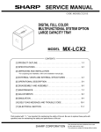
MULTIFUNCTIONAL SYSTEM OPTION
LARGE CAPACITY TRAY
MODEL
MX-LCX3
CONTENTS
[1] PRODUCT OUTLINE. . . . . . . . . . . . . . . . . . . . . . . . . . . . . . . . . . . . . . . . 1-1
[2] SPECIFICATIONS . . . . . . . . . . . . . . . . . . . . . . . . . . . . . . . . . . . . . . . . . . 2-1
[3] UNPACKING AND INSTALLATION
* For unpacking and installation, refer to the installation manual( [3] ).
[4] EXTERNAL VIEWS AND INTERNAL STRUCTURES . . . . . . . . . . . . . . 4-1
[5] OPERATIONAL DESCRIPTION . . . . . . . . . . . . . . . . . . . . . . . . . . . . . . . 5-1
[6] DISASSEMBLY AND ASSEMBLY . . . . . . . . . . . . . . . . . . . . . . . . . . . . . . 6-1
[7] MAINTENANCE. . . . . . . . . . . . . . . . . . . . . . . . . . . . . . . . . . . . . . . . . . . . 7-1
[8] ADJUSTMENTS . . . . . . . . . . . . . . . . . . . . . . . . . . . . . . . . . . . . . . . . . . . 8-1
[9] SIMULATION . . . . . . . . . . . . . . . . . . . . . . . . . . . . . . . . . . . . . . . . . . . . . . 9-1
[10] SELF DIAG MESSAGE AND TROUBLE CODE . . . . . . . . . . . . . . . . . 10-1
[11] ELECTRICAL SECTION . . . . . . . . . . . . . . . . . . . . . . . . . . . . . . . . . . . 11-1
Parts marked with " " are important for maintaining the safety of the set. Be sure to replace these parts with
specified ones for maintaining the safety and performance of the set.
SHARP CORPORATION
This document has been published to be used
for after sales service only.
The contents are subject to change without notice.
CONTENTS
[1] PRODUCT OUTLINE. . . . . . . . . . . . . . . . . . . . . . . . 1-1
[2] SPECIFICATIONS . . . . . . . . . . . . . . . . . . . . . . . . . . 2-1
[3] UNPACKING AND INSTALLATION
* For unpacking and installation, refer to the installation
manual( [3] ).
[4] EXTERNAL VIEWS AND INTERNAL STRUCTURES
1. Motor, clutch, solenoid . . . . . . . . . . . . . . . . . . . . 4-1
2. PWB, sensor, switch, heater . . . . . . . . . . . . . . . . 4-2
[5] OPERATIONAL DESCRIPTION
1. Lift operation . . . . . . . . . . . . . . . . . . . . . . . . . . . . 5-1
2. Paper feed operation . . . . . . . . . . . . . . . . . . . . . 5-2
3. Paper empty detection . . . . . . . . . . . . . . . . . . . . 5-3
[6] DISASSEMBLY AND ASSEMBLY
1. Maintenance parts replacement procedures. . . . 6-1
2. Each unit removal . . . . . . . . . . . . . . . . . . . . . . . . 6-1
3. Major parts removal . . . . . . . . . . . . . . . . . . . . . . 6-3
[7] MAINTENANCE
1. Maintenance system table . . . . . . . . . . . . . . . . . 7-1
[8] ADJUSTMENTS
1. List . . . . . . . . . . . . . . . . . . . . . . . . . . . . . . . . . . . 8-1
2. Details . . . . . . . . . . . . . . . . . . . . . . . . . . . . . . . . . 8-1
[9] SIMULATION
1. List . . . . . . . . . . . . . . . . . . . . . . . . . . . . . . . . . . . 9-1
2. Details of trouble code . . . . . . . . . . . . . . . . . . . . 9-1
[10] SELF DIAG MESSAGE AND TROUBLE CODE
1. Self diag . . . . . . . . . . . . . . . . . . . . . . . . . . . . . . 10-1
2. Trouble code list . . . . . . . . . . . . . . . . . . . . . . . . 10-2
3. Trouble code details . . . . . . . . . . . . . . . . . . . . . 10-2
[11] ELECTRICAL SECTION
1. Wiring diagram . . . . . . . . . . . . . . . . . . . . . . . . . .11-1
2. Block diagram . . . . . . . . . . . . . . . . . . . . . . . . . . .11-3
3. Circuit diagram . . . . . . . . . . . . . . . . . . . . . . . . . .11-5
MX-LCX3
[1]
PRODUCT OUTLINE
Service Manual
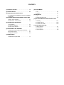
This model is a large capacity paper feed tray installed to the main unit.
It stores 3,000 sheets, eliminating troublesome paper supply.
MX-LCX3
MX-LCX3 PRODUCT OUTLINE 1 – 1
MX-LCX3
[2]
SPECIFICATIONS
Service Manual
Model
Transport reference
Heat reserving heater
Domestic
Overseas
Paper capacity
Normal paper(64g/m2 ,17 lbs bond)
Normal paper(80g/m2 ,21 lbs bond)
Paper size/type/weight
Paper size detection
Paper type setting
Changeover by user
Changeover by service man
(Adjustment of guide and entry of size)
Domestic
Overseas, Inch series
Overseas, AB series
Paper size change system
Factory setting of paper size
Remaining
paper detection
Up
Down
Tray lift time
Troubleshooting of paper jam
Reliability
Life
Power source
Power consumption
Dimensions(W×D×H)
Occupying area(W×D)
Weight
Installation/Maintenance
Maintenance parts
Optional detection
Bundled item
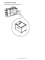
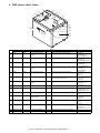
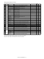
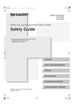
Table 1:Paper size, type, weight
Paper size
Thin paper
Kind/weight
of
applicable
paper
Normal
paper
Cardboard
1(including
gloss paper)
Cardboard 2
Envelope
A3W
A3
B4
A4
A4R
B5
B5R
A5R
12×18
11×17
8.5×14
8.5×13
8.5×11
8.5×11R
7.25×10.5R
5.5×8.5R
8K
*
16K
*
16KR
Postcard
Envelope
Special
55-59g/m2
15-16- lbs bond
60-105g/m2
16-28 lbs bond
106-209g/m2
28+-56- lbs bond
210-256g/m2
56-68 lbs bond
75-90g/m2
20-24 lbs bond
OHP paper
Label paper
Tab paper
* : Available for products for China only.
AB Series
Yes
Yes
Yes
Yes
Yes
Yes
No
No
Yes
Yes
Yes
Yes
Yes
Yes
No
No
No
No
No
No
No
No
Inch
Yes
Yes
Yes
Yes
Yes
Yes
No
No
Yes
Yes
Yes
Yes
Yes
Yes
No
No
No
No
No
No
No
No
Large capacity tray
Center reference
Domestic: Heater kit support
Overseas: Service parts support
3500 sheets
3000 sheets
Refer to Table 1
Not provided (Manually setting from the control panel of the main unit)
Refer to Table 2
Yes (Changeover by manager is allowed)
No
A3
11x17
A3
Paper empty and 6 steps
(100% ,83.3% ,66.7% ,50% ,33.3% ,16.7% ,Paper empty)
max. 30 sec.
max. 15sec.
Can be corrected without separating the unit.
MCBJ:Conforms to the main unit
MCBF:Conforms to the main unit
Conforms to the main unit
Supplied from the main unit
Normal operation:50.4W Lift up:40.8W
670×570×525mm, 26 3/8 × 22 7/16 × 20 21/32 inch
670×570mm, 26 3/8 × 22 7/16 inch
* The rear cabin motor restrictor (10mm) is not included.
Approx. 50kg, 110.1 lbs
Implemented by service man
Paper feed roller
Automatic detection
Parts for installation
Table2:Paper type setting
Normal paper
Printed paper
Recycled paper
Letter head
Perforated paper
Color paper
Cardboard 1
Paper type
Cardboard 2
Thin paper
Label paper
OHP
Tab paper
Envelope
Use type 1 to 7
No
Yes
Yes
No
No
No
No
No
MX-LCX3 SPECIFICATIONS 2 – 1
Yes
Yes
Yes
Yes
Yes
Yes
Yes
No
No
No
No
No
No
Yes
MX-LCX3
Manual
[4]
EXTERNAL VIEWS AND INTERNAL Service
STRUCTURES
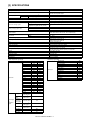
1. Motor, clutch, solenoid
1
Code
LPFM
Signal name
LPFM
Name
Transport motor
Type
Brushless motor
Parts
Function/Operation
Drives the paper feed, and the paper
transport section.
2
LLM
LLM
Lift motor
Brush motor
Lifts or lowers the paper feed table.
3
LPFS
LPFS
Paper feed solenoid
Presses the paper pickup roller onto paper.
4
LTLS
LTLS
Tray lock solenoid
Controls ON/OFF of the tray lock.
5
LTRC
LTRC
Transport clutch
Controls ON/OFF of the transport roller.
6
LPFC
LPFC
Paper feed clutch
Controls ON/OFF of the paper feed roller.
7
LFAN
LFAN
Separation assist
fan
No.
Brushless motor
Assists feeding of paper.
Active condition
CN-G
5pin → Motor rotation clock
4pin → Sync signal: Normal HIGH
3pin → Enable signal: LOW when rotating
CN-B
Lifting: 10pin "24V", 15pin "L"
Lowering: 10pin "L", 15pin "24V"
CN-E 8pin
ON: "L"
OFF: "24V"
CN-D
Lock: "L" ("24V" after 0.5sec)
Release: "L" ("24V" after 0.5sec)
CN-F 15pin
ON: "L"
OFF: "24V"
CN-F 11pin
ON: "L"
OFF: "24V"
CN-D 15, 16pin
ON: "L"
OFF: "5V"
MX-LCX3 EXTERNAL VIEWS AND INTERNAL STRUCTURES 4 – 1
2. PWB, sensor, switch, heater
4
5
3
6
2
1
7
8
9
10
11
12
14
13
15
No.
Parts
1
Code
LPUD
Signal name
LPUD
Name
LCC paper front surface
sensor
Type
Function/Operation
Detects paper front surface position
2
LUD
LUD
Upper limit sensor
Detects the paper upper limit position.
3
LPFD
LPFD
Transport sensor
Detects paper transport.
4
LTOD
LTOD
The main unit connection
sensor
Detects connection to the main unit.
5
LDSW
LDSW
Upper open/close switch
Detects open/close of the upper door.
6
LLSW
LLSW
Upper limit switch
Protects the paper feed unit from breakage
due to lifting the tray too much.
7
LPED
LPED
Paper presence/empty
sensor
Detects paper presence/empty on the paper
tray.
8
9
A3-LCC PWB
LCSW
—
LCSW
A3-LCC PWB unit
Cassette detection switch
Controls and drives the LCC.
The tray insertion is detected.
10
LRE
LRE
Lift motor encoder
The lift motor rotation is detected.
11
LWRSW
LWRSW
LCC reverse-winding
detection switch
Detects lift motor reverse-winding
12
LTLD
LTLD
Tray lock sensor
Detects the tray lock
13
LDD
LDD
Lower limit sensor
The lower limit of the tray is detected.
14
15
DOWN SW PWB
LTLLED
—
LTLLED
Lowering SW PWB unit
Tray LED
Shifts the tray to the paper supply position.
The tray state is displayed with LED.
MX-LCX3 EXTERNAL VIEWS AND INTERNAL STRUCTURES 4 – 2
Active condition
CN-C 8pin
Paper detected: "L"
Paper not detected: "H"
CN-E 5pin
Upper limit: "H"
Other than Upper limit: "L"
CN-E 11pin
Paper detected: "L"
Paper not detected: "H"
CN-F 19pin
Connected: "L"
Not connected: "H"
CN-F 4pin 6pin
Open: "L"
Close: "24V"
CN-F 7pin
Normal: "24V"
Detection: "L"
CN-E 2pin
Paper present: "L"
Paper empty: "H"
CN-B 7pin
Cassette insertion: "24V"
Cassette puling out: "L"
CN-C 4pin
Pulse
CN-B 14pin
Normal: "24V"
Detection: "L"
CN-C 7pin
Lock: "H"
Release: "L"
CN-C 3pin
Lower limit: "H"
Other than Lower limit: "L"
MX-LCX3
[5] OPERATIONAL DESCRIPTION
Service Manual
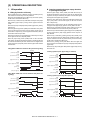
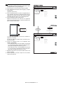
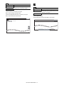
1. Lift operation
B. Lowering operation by paper empty detection
or pressing the tray SW
A. Lifting by insertion of the tray
When insertion of the tray is detected, the tray is locked by the tray
lock solenoid so that the tray cannot be pulled out.
When tray lock is settled by turning ON the tray lock sensor (LTLD),
the lift motor is turned ON to lift the tray.
When the tray is lifted, the tray LED blinks and stops at the paper
feed position (upper limit) by turning ON the upper limit sensor
(LUD).
When the tray stops at the paper feed position (upper limit), the tray
LED turns on.
When the paper empty sensor (LPED) turns ON within 1097 pulses
of the encoder signal from start of the tray lifting, the lift motor is
turned OFF to stop the tray, and the paper feed solenoid (LPFS) is
turned ON to lower the pick roller.
After that, the lift motor is turned ON again to lift the tray and stop it
at the upper limit sensor (LUD) ON position.
When the paper empty sensor (LPED) does not turn ON within
1097 pulses, the paper feed solenoid (LPFS) is turned ON with the
lift motor ON to lower the pick roller. The lift motor is stopped at the
upper limit sensor (LUD) ON position and the paper feed solenoid
is turned OFF.
Lifting (When LPED turns ON within 1097 pulses during lifting)
When the paper empty sensor (LPED) turns OFF with the tray at
the paper feed position (upper limit) or when the tray SW (LTLSW)
is pressed, the tray is lowered by 542 pulses of the encoder signal
and stopped at the paper supply position.
When the lower limit sensor (LDD) turns ON before lowering the
tray by 542 pulses of the encoder signal, the lift motor is turned
OFF to stop the tray.
When the tray is moving down, the tray LED blinks. When the tray
is stopped at the paper supply position, the tray LED turns OFF.
When the tray is stopped at the paper supply position, the tray lock
solenoid releases the lock so that the tray can be pulled out.
When the tray is lowered with the paper empty sensor (LPED) OFF,
the tray remains at the paper supply position and the tray lock is
kept released.
When the tray is lowered by pressing the tray SW (LTLSW), if the
tray is not pulled out from the paper supply position for 90sec, the
tray lock solenoid locks the tray. When the tray is locked securely,
the lift motor is turned ON to lift the tray.
When the tray is lifting, the tray LED blinks. When the upper limit
sensor (LUD) is turned ON, the tray stops at the paper feed position
(upper limit).
When the tray stop at the paper feed position (upper limit), the tray
LED turns ON.
200msec
Lowering operation (when paper empty is detected)
LLM
(Lift motor output)
LDD
(Lower limit sensor)
LLM
(Lift motor output)
LDD
(Lower limit sensor)
LUD
(Upper limit sensor)
LUD
(Upper limit sensor)
LPED
(Paper empty detection)
LPSL
(Solenoid)
LPED
(Paper empty detection)
Within 1097 pulses
LTLSW
(Tray SW)
LRE
(Encoder signal)
Lifting (When LPED does not turn ON within 1097 pulses during lifting)
LLM
(Lift motor output)
LDD
(Lower limit sensor)
LUD
(Upper limit sensor)
LPED
(Paper empty detection)
LRE
(Encoder signal)
Lowering operation (when tray SW is pressed)
LLM
(Lift motor output)
LDD
(Lower limit sensor)
LUD
(Upper limit sensor)
LPSL
(Solenoid)
542
LRE
(Encoder signal)
LPED
(Paper empty detection)
1097
LTLSW
(Tray SW)
LRE
(Encoder signal)
MX-LCX3 OPERATIONAL DESCRIPTION 5 – 1
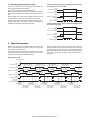
Less than 542
C. Lowering operation by paper supply
If the tray is pulled out when it is at the paper supply position, the
tray lock solenoid keep the lock released.
When the tray is pulled out, the tray LED turns OFF.
When the paper front surface sensor (LPUD) is turned ON for 2sec
while the tray is pulled out, the lift motor is turned ON to lower the
tray.
When the paper front surface sensor (LPUD) is turned OFF while
the tray is lowered, the lift motor is turned OFF to stop the tray.
When the lower limit sensor (LDD) is turned ON while the tray is
lowered, the lift motor is turned OFF to stop the tray regardless of
the state of the paper front surface sensor (LPUD).
Lowering operation (when paper is supplied or when the paper
front surface sensor is turned ON)
LLM
(Lift motor output)
LDD
(Lower limit sensor)
LPUD
(Paper front surface
sensor)
2 [sec]
LRE
(Encoder signal)
Lowering operation (when paper is supplied or when the lower
limit sensor is turned ON)
LLM
(Lift motor output)
LDD
(Lower limit sensor)
LPUD
(Paper front surface
sensor)
2 [sec]
LRE
(Encoder signal)
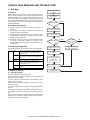
2. Paper feed operation
When the tray is stationary at the paper feed position (upper limit
sensor: LUD ON position) and there is paper on the tray, paper
feed operation can be performed.
Paper feed operation is performed by the transport motor (LPFM),
the transport clutch (LTRC), the paper feed clutch (LPFC), and the
paper feed solenoid (LPFS) at the following timing.
When the transport clutch (LTRC) is turned ON with the transport
motor (LPFM) ON (rotating), the transport roller rotates. When the
paper feed clutch (LPFC) is turned on under this state, the paper
feed roller and the take-up roller rotate. When the paper feed solenoid (LPFS) is turned ON, the take-up roller is pushed down to
press paper.
Paper feed time chart
Paper feed start
LPFM
(Transport motor)
LTD
(Transport sensor)
LPFS
(Paper feed solenoid)
Clearance-betweenpapers control timer
Clearance-betweenpapers control timer
Clearance-betweenpapers control timer
Clearance-betweenpapers control timer
PIC drop timer
PIC drop timer
PIC drop timer
PIC drop timer
Paper feed clutch
OFF timer
Paper feed clutch
OFF timer
Paper feed clutch
OFF timer
Paper feed clutch
OFF timer
Paper feed clutch
OFF timer
LPFC
(Paper feed clutch)
LTRC
(Transport clutch)
TRC-LCC
(Main unit
synchronous signal)
Preliminary
paper feed start
First sheet
Resist stop
Resist stop
Resist stop
Resist stop
Preliminary
Preliminary
Preliminary
Preliminary
paper feed start
paper feed start
paper feed start
paper feed start
Second sheet
Third sheet
Fourth sheet
Fifth sheet
Preliminary paper
Preliminary paper
Preliminary paper
Preliminary paper
Preliminary paper
feed complete
feed complete
feed complete
feed complete
feed complete
Paper feed start
Paper feed start
Paper feed start
Paper feed start
Paper feed start
MX-LCX3 OPERATIONAL DESCRIPTION 5 – 2
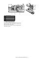
1
5
6
7
2
1
2
3
4
5
6
7
3
4
Paper feed roller clutch
Take-up roller
Paper feed roller
Paper feed solenoid
Transport clutch
Transport motor
Lift-up motor
3. Paper empty detection
When the tray lifts and stops at the paper feed position and during
paper feed operation, paper presence/empty is detected by the
paper presence/empty sensor (LPED).
When paper empty is detected in the tray during paper feeding,
paper feeding is stopped.
MX-LCX3 OPERATIONAL DESCRIPTION 5 – 3
MX-LCX3
[6]
DISASSEMBLY AND ASSEMBLY
Service Manual
1. Maintenance parts replacement
procedures
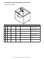
2. Each unit removal
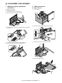
A. Paper feed roller
1)
Pull out the tray.
2)
Remove the screw, and remove the left front cabinet.
3)
Open the upper cover, and remove the screws.
4)
Remove the upper cabinet.
1)
Pull the lever, and open the upper cover.
2)
Remove the screw, and remove the sheet.
3)
Remove the pawl, and remove the pickup roller and the paper
feed roller.
4)
Loosen the screw, and remove the paper guide block.
5)
Remove the pawl, and remove the reverse roller.
A. Paper feed unit
MX-LCX3 DISASSEMBLY AND ASSEMBLY 6 – 1
5)
Disconnect the connectors.
C. Lift drive unit
6)
Remove the screws, and remove the paper feed unit.
1)
Check that there is no paper, and lower the paper feed table to
the lower limit with the main unit simulation mode.
2)
Remove the screws, and remove the rear cabinet.
3)
Remove the connectors.
4)
Remove the screws, and remove the lift drive unit.
B. Paper feed tray
1)
Pull out the tray.
2)
Remove the upper cabinet. (Refer to "A. Paper feed unit")
3)
Remove the left front cabinet. (Refer to "A. Paper feed unit")
4)
Remove the harness.
5)
Remove the screws from the left and right rail sections, and
remove the tray unit from the rail.
MX-LCX3 DISASSEMBLY AND ASSEMBLY 6 – 2
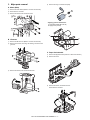
3. Major parts removal
4)
Remove the ring, and remove the pulley.
A. Motor (Main)
1)
Remove the rear cabinet. (Refer to "2. Each unit removal")
2)
Disconnect the connector.
3)
Remove the screws, and remove the motor.
* Applying grease at maintenance
A: Apply MOLYKOTE (BR-2 PLUS)
B: Apply FLOIL (G313S)
A
A
B. Lift motor
1)
Remove the lift drive unit. (Refer to "2. Each unit removal")
2)
Remove the screws, the E-ring, the bearing, and remove the
gear unit.
B
C. Paper feed solenoid
3)
1)
Remove the paper feed unit. (Refer to "2. Each unit removal")
2)
Remove the cover.
3)
Remove the screw, and remove the unit.
Remove the screws, and remove the lift motor.
Disconnect the connector.
MX-LCX3 DISASSEMBLY AND ASSEMBLY 6 – 3
4)
Remove the screws, and remove the solenoid.
5)
Remove the E-ring, and remove the torque limiter.
1
2
3
4
D. Torque limiter
1)
Remove the paper feed unit. (Refer to "2. Each unit removal")
2)
Remove the screw, and remove the paper guide block.
E. Transport roller
1)
Remove the paper feed unit. (Refer to "2. Each unit removal")
2)
Loosen the screws, and remove the paper guide block.
3)
Remove the rear cover, and disconnect the connector. (Refer
to "D. Torque limiter")
4)
Remove the screw and the E-ring, and remove the parts.
Remove the transport roller.
3)
Remove the screws, and remove the rear cover.
F. Handling solenoid
4)
1)
Check that there is no paper, and lower the paper feed table to
the lower limit with the main unit simulation mode.
2)
Pull out the tray.
3)
Remove the screws.
Disconnect the connector.
MX-LCX3 DISASSEMBLY AND ASSEMBLY 6 – 4
4)
Remove the front cabinet, and disconnect the connector.
4)
Disconnect the connector, and remove the harness.
Remove the drive frame.
5)
Remove the connector and the screw.
5)
Remove the clutch unit.
Remove the E-ring, and remove the clutch.
6)
Remove the screws, and remove the solenoid.
2
3
1
G. Clutch
1)
Remove the upper cabinet.
2)
Remove the rear cabinet.
3)
Remove the left rear cabinet.
MX-LCX3 DISASSEMBLY AND ASSEMBLY 6 – 5
[7] MAINTENANCE
MX-LCX3
Service Manual
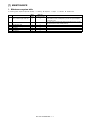
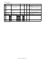
1. Maintenance system table
✕ : Checking (clean, replace or adjust as required)
No.
Part name
When
calling
{ : Cleaning
▲ : Replace
∆ : Adjust
Main unit
maintenance cycle
1
Pick-up roller/each paper feed roller
✕
{
2
Torque limiter
✕
✕
3
4
5
6
Each transport rollers
Each transport paper guides
Each gears
Each belts
✕
{
✕
{
{
✕
✕
7
Each sensors
✕
✕
✩ : Lubricate
: Position shift
Remarks
As a rough guide, these rollers should be replaced when the LCC paper feed
counter reaches a value of 100K (Sim22-9) or when one year has elapsed
since the start of use.
As a rough guide, the torque limiter should be replaced when the LCC paper
feed counter reaches a value of 800K (Sim22-9).
MX-LCX3 MAINTENANCE 7 – 1
MX-LCX3
[8]
ADJUSTMENTS
Service Manual
Each adjustment item in the adjustment item list is indicated with its JOB number. Perform the adjustment procedures in the sequence of Job
numbers from the smallest to the greatest.
However, there is no need to perform all the adjustment items. Perform only the necessary adjustments according to the need.
Unnecessary adjustments can be omitted. Even in this case, however, the sequence from the smallest to the greatest JOB number must be
observed.
If the above precaution should be neglected, the adjustment would not complete normally or a trouble may occur.
1. List
Job No.
ADJ 1
ADJ 2
Adjustment item list
Print off-center adjustment
Resist amount adjustment
ADJ 2A
ADJ 2B
Change in the resist amount adjustment/deflection amount correction value
Adjustment of the print lead edge adjustment
Simulation to
be used
50-10
51-02
50-05
2. Details
[Switching of screen]
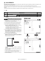
ADJ 1 Print off-center adjustment
1)
Execute SIM.50-10 by the key operation of the machine. Then,
the displays shown on the right side appear.
2)
The print off-center adjustment value can be set for each tray.
3)
Press the [↓] key on the touch panel to select “G:50:LCC”.
4)
Then, enter your desired adjustment value with the [10] key.
(Default: 50
0
TEST
PAPER CENTER OFFSET SETUP
G:
50
㨇
㨉
Adjustment range: from 1 to 99)
* If the adjustment value is decreased by 1, the main scanning
print position is shifted to the front side by 0.1mm.
* If the adjustment value is increased by 1, the main scanning
print position is shifted to the rear side by 0.1mm.
5)
6)
CLOSE
SIMULATION NO50-10
When the [EXECUTE] button is pressed, the [EXECUTE] button is highlighted, currently set value is saved into the
EEPROM and the RAM, and printing for adjustment pattern
image is started. After printing is finished, the [EXECUTE] button returns to the normal display status.
A㧦100
㧧
B㧦 50
㧧 MFT
BK-MAG
C㧦 50
㧧 CS1
D㧦 50
㧧 CS2
E㧦 50
㧧 CS3
F㧦 50
㧧 CS4
G㧦 50
㧧 LCC
H㧦 50
㧧 ADU
I㧦
1
㧧 MULTICOUNT
J㧦
2
㧧 PAPER㧦CS1
K㧦 1
㧧 DUPLEX㧦NO
OK
EXECUTE
Check the adjustment pattern image position.
Measure the dimensions of the void area in the adjustment
pattern front and rear frame directions, and ensure that they
satisfy the conditions shown below.
10
Key
EXECUTE
EXECUTE
Printing is finished
A
0
TEST
CLOSE
SIMULATION NO50-10
PAPER CENTER OFFSET SETUP
+ 3.0mm
A-B = 0 -
G:
60
㨇
B
If condition of A - B = 0±3.0mm is satisfied, no adjustment is
necessary.
If it does not satisfy the condition above, execute the procedures shown below.
7)
Change the adjustment value. Repeat the steps from 4) to 6)
until the condition described in the step 6) is satisfied.
8)
After the adjustment is finished, escape from the simulation
mode with the reset key.
MX-LCX3 ADJUSTMENTS 8 – 1
㨉
A㧦 100
㧧 BK-MAG
B㧦 50
㧧 MFT
C㧦 50
㧧 CS1
D㧦 50
㧧 CS2
E㧦 50
㧧 CS3
F㧦 50
㧧 CS4
G㧦 50
㧧 LCC
H㧦 50
㧧 ADU
I㧦
1
㧧 MULTICOUNT
J㧦
2
㧧 PAPER㧦CS1
K㧦 1
㧧 DUPLEX㧦NO
EXECUTE
OK
<<Description of items>>
Item
A
B
Display item and details
BK-MAG
MFT
C
D
E
F
G
H
I
J
CS1
CS2
CS3
CS4
LCC
ADU
MULTI COUNT
PAPER
K
DUPLEX
MFT
CS1
CS2
CS3
CS4
LCC
YES
NO
Descriptions
Main scanning print magnification BK
Print off-center adjustment value (manual)
Print off-center adjustment value
(cassette 1)
Print off-center adjustment value (cassette 2)
Print off-center adjustment value (cassette 3)
Print off-center adjustment value (cassette 4)
Print off-center adjustment value (LCC)
Print off-center adjustment value (ADU)
Number of printed sheets
Cassette selection
Manual
Cassette 1
Cassette 2
Cassette 3
Cassette 4
LCC
Double sided print selection
Select
Not select
ADJ 2 Resist amount adjustment
2-A Changing resist amount adjustment/
deflection amount correction value
1)
Execute SIM.51-2 by the key operation of the machine. Then,
the displays shown on the right side appear.
Default
100
50
Writing
Yes
Yes
1 to 99
1 to 99
1 to 99
1 to 99
1 to 99
1 to 99
1 to 999
50
50
50
50
50
50
1
2
(CS1)
Yes
Yes
Yes
Yes
Yes
Yes
No
No
1(NO)
No
1 to 6
0 to 1
[Switching of screen]
0
TEST
REGIST ROLLER ADJUSTMENT
;
MANUAL HEAVY PAPER1(L)
;
MANUAL OHP1
P: 50
;
MANUAL ENV
Q: 50
;
ADU PLAIN PAPER(S)
R: 50
;
ADU PLAIN PAPER(L)
Then, enter your desired adjustment value with the [10] key.
S:
50
;
ADU HEAVY PAPER1(S)
(Default: 50
T: 50
;
ADU HEAVY PAPER1(L)
U: 50
;
A4LCC
V: 50
;
A3LCC(S)
W: 50
;
A3LCC(L)
X: 50
;
A3LCC HEAVY PAPER‚P(S)
Y: 50
;
Select the [ENGIN] button.
Press the [↓] key on the touch panel to select “V:50:A3LCC
(S)”.
V:
50
㨇
㨉
Ajustment range: from 1 to 99)
* As the adjustment value is increased, the deflection amount
is also increased. As the adjustment value is decreased, the
deflection amount is also decreased.
(If the adjustment value is changed by “1”, the stop timing is
changed by 0.1mm (1.0msec).)
6)
CLOSE
SIMULATION NO51-02
O: 50
3)
5)
1
2
3
4
5
6
0
1
N: 50
2)
4)
Setting range
60 to 140
1 to 99
After the adjustment value is entered, press the [OK] key on
the touch panel to save the set value.
REGI2
REGI1
A3LCC HEAVY PAPER‚P(L)
ENGIN
After the adjustment is finished, escape from the simulation
mode with the reset key.
㪈㪇
OK
Key
OK
0
TEST
CLOSE
SIMULATION NO51-02
REGIST ROLLER ADJUSTMENT
V:
60
㨇
REGI1
MX-LCX3 ADJUSTMENTS 8 – 2
㨉
REGI2
N: 50
;
MANUAL HEAVY PAPER1(L)
O: 50
;
MANUAL OHP1
P: 50
;
MANUAL ENV
Q: 50
;
ADU PLAIN PAPER(S)
R: 50
;
ADU PLAIN PAPER(L)
S:
;
ADU HEAVY PAPER1(S)
T: 50
;
ADU HEAVY PAPER1(L)
U: 50
;
A4LCC
V: 60
;
A3LCC(S)
W: 50
;
A3LCC(L)
X: 50
;
A3LCC HEAVY PAPER‚P(S)
Y: 50
;
A3LCC HEAVY PAPER‚P(L)
50
ENGIN
OK
<<Setting range and defaults of set values>>
Item
Button
A
B
C
D
E
F
G
H
I
J
K
L
M
N
O
P
Q
R
S
T
U
V
W
X
Y
ENGIN
Item to be displayed
TRAY1(S)
TRAY2(S)
TRAY3 PLAIN PAPER
(S)
TRAY3 PLAIN PAPER
(L)
TRAY3 HEAVY
PAPER1 (S)
TRAY3 HEAVY
PAPER1 (L)
TRAY4 PLAIN PAPER
(S)
TRAY4 PLAIN PAPER
(L)
TRAY4 HEAVY
PAPER1 (S)
TRAY4 HEAVY
PAPER1 (L)
MANUAL PLAIN
PAPER (S)
MANUAL PLAIN
PAPER (L)
MANUAL HEAVY
PAPER1 (S)
MANUAL HEAVY
PAPER1 (L)
MANUAL OHP1
MANUAL ENV
ADU PLAIN PAPER (S)
ADU PLAIN PAPER (L)
ADU HEAVY PAPER1
(S)
ADU HEAVY PAPER1
(L)
A4LCC
A3LCC (S)
A3LCC (L)
A3LCC HEAVY
PAPER1 (S)
A3LCC HEAVY
PAPER1 (L)
Host machine tray 1, deflection adjustment value (small size)
Host machine tray 2, deflection adjustment value (small size)
Host machine tray 3, deflection adjustment value
(normal paper, small size)
Host machine tray 3, deflection adjustment value
(normal paper, large size)
Host machine tray 3, deflection adjustment value
(Cardboard 1, small size)
Host machine tray 3, deflection adjustment value
(Cardboard 1, large size)
Host machine tray 4, deflection adjustment value
(Normal paper, small size)
Host machine tray 4, deflection adjustment value
(Normal paper, large size)
Host machine tray 4, deflection adjustment value
(Cardboard 1, small size)
Host machine tray 4, deflection adjustment value
(Cardboard 1, large size)
Not more than LT size
Not more than LT size
Setup
range
1 to 99
1 to 99
Not more than LT size
1 to 99
50
Not less than LT size
1 to 99
50
Not more than LT size
1 to 99
50
Not less than LT size
1 to 99
50
Not more than LT size
1 to 99
50
Not less than LT size
1 to 99
50
Not more than LT size
1 to 99
50
Not less than LT size
1 to 99
50
Manual tray, deflection adjustment value (Normal paper, small size)
Not more than LT size
1 to 99
50
Manual tray, deflection adjustment value (Normal paper, large size)
Not less than LT size
1 to 99
50
Manual tray, deflection adjustment value (Cardboard1, small size)
Not more than LT size
1 to 99
50
Manual tray, deflection adjustment value (Cardboard1, large size)
Not less than LT size
1 to 99
50
Manual tray, deflection adjustment value (OHP1)
Manual tray, deflection adjustment value (Envelope)
ADU, deflection adjustment value (normal paper, small size)
ADU, deflection adjustment value (normal paper, large size)
Not more than LT size
Not less than LT size
1 to 99
1 to 99
1 to 99
1 to 99
50
50
50
50
ADU, deflection adjustment value (Cardboard1, small size)
Not more than LT size
1 to 99
50
ADU, deflection adjustment value (Cardboard1, large size)
Descriptions (Mode, original, paper feeed speed)
Feed direction
Default
50
50
Not less than LT size
1 to 99
50
A4LCC, deflection adjustment value
A3LCC deflection adjustment value (Normal paper, small size)
A3LCC deflection adjustment value (Normal paper, large size)
Not more than LT size
Not less than LT size
1 to 99
1 to 99
1 to 99
50
50
50
A3LCC deflection adjustment value (Cardboard, small size)
Not more than LT size
1 to 99
50
A3LCC deflection adjustment value (Cardboard, large size)
Not more than LT size
1 to 99
50
<Notation of (Large size), (Small size)>
(Small size): Length of paper in the feeding direction is not more than LT size (216mm).
(Large size): Length of paper in the feeding direction exceeds LT size (216mm).
MX-LCX3 ADJUSTMENTS 8 – 3
2-B Print lead edge adjustment
1)
Execute SIM.50-5 by the key operation of the machine. Then,
the displays shown on the right side appear.
2)
Press the [↓] key on the touch panel to select “E:PAPER”.
3)
Then, enter the adjustment value 6 with the [10] key, and press
the [OK] button.
(Adjustment value 6: LCC)
4)
5)
When the [EXECUTE] button is pressed, the [EXECUTE] button is highlighted, and printing for adjustment pattern image is
started with the currently set value. After printing is finished,
the [EXECUTE] button returns to the normal display status.
[Switching of screen]
0
CLOSE
SIMULATION NO50-05
TEST
LEAD EDGE ADJUSTMENT VALUE(PRINTER)
A:
[
30
1 㨪 99
A㧦 30
㧧
B㧦 20
㧧 DEN-B
C㧦 20
㧧 FRONT/REAR
]
DEN-C
D㧦 1
㧧 MULTI COUNT
E㧦 2
㧧
PAPER : CS1
F㧦 1
㧧
DUPLEX : NO
Check the adjustment pattern image position.
Measure the dimensions of the void area in the adjustment
pattern right and left frame directions, and ensure that they satisfy the conditions shown below.
A
EXECUTE
OK
EXECUTE
+ 2.0mm
A = 4.0 + 2.0mm
B = 4.0 -
EXECUTE
Printing is finished
0
B
TEST
If condition of A=4.0±2.0mm, B=4.0±2.0mm is satisfied, no
adjustment is necessary.
If it does not satisfy the condition above, execute the procedures shown below.
6)
CLOSE
SIMULATION NO50-05
LEAD EDGE ADJUSTMENT VALUE(PRINTER)
A:
㨇 1㨪
40
99 㨉
Change the adjustment values of the adjustment items
A(DEN-C) and B(DEN-B).
A㧦 40
㧧
B㧦 20
㧧 DEN-B
C㧦 20
㧧 FRONT/REAR
DEN-C
D㧦 1
㧧 MULTI COUNT
E㧦 2
㧧
PAPER : CS1
F㧦 1
㧧
DUPLEX : NO
* As the adjustment value of the item A(DEN-C) is decreased
by 1, the print start position is moved to the lead edge side of
paper against the paper feed direction by 0.1mm.
* As the adjustment value of the item B(DEN-B) is decreased
by 1, the print range is increased to the trailing edge side of
paper against the paper feed direction by 0.1mm.
7)
Repeat the steps from 4) to 6) until the condition shown in the
step 5) is satisfied.
8)
After the adjustment is finished, escape from the simulation
mode with the reset key.
MX-LCX3 ADJUSTMENTS 8 – 4
EXECUTE
OK
<Description of items>
Item
Display items and
details
Descriptions
Setup range
Default
Writing
A
DEN-C
Print lead edge adjustment
1 to 99
30
Yes
B
DEN-B
Sub scanning direction print area
adjustment
1 to 99
20
Yes
C
FRONT/REAR
FRONT/REAR void amount
adjustment
1 to 99
20
Yes
D
MULTI COUNT
Number of printed sheets
1 to 999
1
No
2
(CS1)
No
1
(NO)
No
E
PAPER
F
DUPLEX
MFT
CS1
CS2
CS3
CS4
LCC
YES
NO
Cassette selection
Double-sided print
selection
Manual 1
Cassette 1
Cassette 2
Cassette 3
Cassette 4
LCC
Selected
Not selected
1 to 6
0 to 1
1
2
3
4
5
6
0
1
* The item name for the items J and K is detailed display.
Example: PAPER: CS1
MX-LCX3 ADJUSTMENTS 8 – 5
Remarks
Adjustment value for matching to the print lead
edge for printer.
As the adjustment value of this item is decreased
by 1, the print start position against the paper
feeding direction is moved to the leading edge side
by 0.1mm.
Amount of void to be created at the trailing edge of
paper. As the adjustment value of the item B(DENB) is decreased by 1, the sub scanning print range
adjustment value is decreased by 0.1mm.
Amount of void to be created at the right and left
edges of paper. As the value is increased, the void
amount is increased.
MX-LCX3
[9]
SIMULATION
Service Manual
1. List
Code
Main
Function (purpose)
Sub
2
4
3
15
Purpose
Used to check the operations of the sensors and detectors in the large capacity tray
(LCC) and the control circuit.
Used to check the operations of the loads in the large capacity tray (LCC) and the
control circuit.
Operation test/Check
Operation test/Check
5
Used to check the operations of the clutch (LTRC) in the LCC and the monitor.
Operation test/Check
-
Used to cancel the self-diag "U6-09 (large capacity paper feed tray)" trouble.
Clear/cancel (Trouble
etc.)
2. Details of trouble code
Section
Large capacity tray
(LCC)
Large capacity tray
(LCC)
Large capacity tray
(LCC)
LCC
4-3
Operation test/Check
Purpose
4
Function (Purpose) Used to check the operations of the loads
in the large capacity tray (LCC) and the
control circuit.
4-2
Function (Purpose) Used to check the operations of the sensors and detectors in the large capacity tray
(LCC) and the control circuit.
The operating conditions of the sensors and detectors are displayed.
Sensors and detectors which are turned on are highlighted.
TEST
LCC transport sensor
LCC tray upper limit detection
LCC tray lower limit detection
LCC tray paper empty detection
LCC tray insertion detection
LCC upper open/close detection SW
LCC lift motor encoder detection
LCC 24V power monitor
LCC upper limit SW
LCC paper upper surface detection SW
LCC reverse winding detection SW
LCC tray lift SW
LCC tray lock sensor
LCC illegal paper detection SW
LCC main unit connection sensor
2) Press [EXECUTE] key.
MX-LCX3
LPFM
LLM
LPFC
LPFS
LTRC
LTLED
LTLC
LFAN
TEST
LCC transport motor
LCC lift motor
LCC paper feed clutch
LCC paper feed solenoid
LCC transport clutch
LCC tray LED lamp
LCC tray lock clutch
LCC separation auxiliary fan
CLOSE
SIMULATION NO.04-03
LCC LOAD CHECK
LPFM
LLM
LPFC
LPFS
LTRC
CLOSE
SIMULATION NO.04-02
LCC SENSOR CHECK
LPFD
1) Select a target of the operation check with the touch panel.
When [EXECUTE] is pressed, the operation is stopped.
Operation/Procedure
<MX-LCX3>
LPFD
LUD
LDD
LPED
LCD
LDSW
LRE
L24VM
LLSW
LPUSW
LRRSW
LTLSW
LTLD
LIPSW
LTOD
Operation/Procedure
The selected load is operated.
Large capacity tray (LCC)
Section
Large capacity tray (LCC)
Section
Operation test/Check
Purpose
LUD
LDD
LPED
LCD
LDSW
LRE
L24VM
LLSW
LTOD
EXECUTE
1/1
MX-LCX3 SIMULATION 9 – 1
1/1
4-5
15
Operation test/Check
Purpose
Function (Purpose) Used to check the operations of the clutch
(LTRC) in the LCC and the monitor.
Large capacity tray (LCC)
Section
15-Clear/cancel (Trouble etc.)
Purpose
Function (Purpose) Used to cancel the self-diag "U6-09 F3-12,
F3-22(large capacity paper feed tray, paper
feed tray1, 2)" trouble.
Operation/Procedure
1) Press LTRC key to check the sync signal.
When normal: ON When abnormal: OFF
LCC
Section
2) Press the highlighted LTRC key to check the sync signal.
Operation/Procedure
When normal: OFF When abnormal: ON
1) Press [EXECUTE] key.
2) Press [YES] key to execute cancellation of the trouble.
TEST
SIMULATION NO.04-05
CLOSE
LCC SYNCRONIZING SIGNAL CHECK
LTRC
TEST
:
CLOSE
SIMULATION NO.15
LTRC OFF
LCC TROUBLE CANCELLATION
ARE YOU SURE?
1/1
MX-LCX3 SIMULATION 9 – 2
YES
NO
EXECUTE
Service
Manual
[10] SELF DIAG MESSAGE AND TROUBLE
CODE
MX-LCX3
1. Self diag
Monitors the machine
conditions.
A. General
When a trouble occurs in the machine or when the life of a consumable part is nearly expired or when the life is expired, the machine
detects and displays it on the display section or notifies to the user
or the serviceman by voice messages. This allows the user and the
serviceman to take the suitable action. In case of a trouble, this feature notifies the occurrence of a trouble and stops the machine to
minimize the damage.
B. Function and purpose
1)
Securing safety. (The machine is stopped on detection of a
trouble.)
2)
The damage to the machine is minimized. (The machine is
stopped on detection of a trouble.)
3)
By displaying the trouble content, the trouble position can be
quickly identified. (This allows to perform an accurate repair,
improving the repair efficiency.)
4)
Preliminary warning of running out of consumable parts allows
to arrange for new parts in advance of running out. (This
avoids stopping of the machine due to running out the a consumable part.)
C. Self diag message kinds
The self diag messages are classified as shown in the table below.
Class 1
User
Serviceman
Class 2
Other
Warning
Trouble
Other
Warning of troubles which can be recovered by
the user. (Paper jam, consumable part life
expiration, etc.)
Warning of troubles which can be recovered only
by a serviceman. (Motor trouble, maintenance,
etc.)
—
Warning to the user, not a machine trouble
(Preliminary warning of life expiration of a
consumable part, etc.)
Warning of a machine trouble. The machine is
stopped.
—
D. Self diag operation
Detects/analyzes
the content.
Warning
Trouble/Warning
Trouble
The machine is stopped.
The content is displayed.
Trouble/Warning
Warning
Trouble
Troubleshoot the cause.
Repair
Cancel the selfdiagnostic message with
the diagnostics
(test commands).
Reset
Standby state
(1) Self diag operation
The machine always monitors its own state.
When the machine recognizes a trouble, it stops the operation and
displays the trouble message.
A warning message is displayed when a consumable part life is
nearly expired or is expired.
When a warning message is displayed, the machine may be or
may not be stopped.
The trouble messages and the warning messages are displayed by
the LCD.
Some trouble messages are automatically cleared when the trouble is repaired. Some other troubles must be cleared by a simulation.
Some warning messages of consumable parts are automatically
cleared when the trouble is repaired. Some other warning messages must be cleared by a simulation.
MX-LCX3 SELF DIAG MESSAGE AND TROUBLE CODE 10 – 1
A consumable
part has reached
its lifetime.
YES
Replace or supply
the consumable part.
NO
2. Trouble code list
MAIN
CODE
U6
SUB
CODE
09
20
21
22
23
24
51
Title (Content)
Lift motor trouble
Communication trouble
Transport motor trouble
24V trouble
Tray descending trouble
Tray lock trouble
LCC incompatibility trouble
Section
LCC
LCC
LCC
LCC
LCC
LCC
LCC
Operation mode
Countermeasure (Remedy)
When the tray is working
LCC communication
Paper feed
Power ON
When the tray is working
When the tray is working
Power ON
Note
Check connection.
Turn OFF/ON the power.
Check connection.
Check connection.
Check connection.
Check connection.
Check connection.
3. Trouble code details
U6-09
LCC lift motor trouble
Trouble content
Section
Case 1
Cause
Check
and
Remedy
U6-20
LCC communication trouble
Trouble content
Section
Case 1
Cause
Check
and
Remedy
U6-21
Cause
Check
and
Remedy
U6-22
LCC communication error. Communication line test
error after turning ON the power or canceling the
exclusive simulation. LCC and machine model
codes discrepancy error
PCU
Connector and harness connection trouble or
disconnection, LCC control PWB trouble, control
(PCU) PWB trouble, malfunction due to electrical
noises
Turn OFF/ON the power to cancel the trouble.
Check the connector and the harness of the
communication line.
LCC transport motor trouble
Trouble content
Section
Case 1
• The encoder input value is not changed in
0.2sec (1st time)/0.5sec (2nd time and later)
after rotation of the motor.
• The motor is rotated for 48sec or more.
PCU
Sensor trouble, LCC control PWB trouble, gear
breakage, lift motor trouble
Use SIM4-2 and 4-3 to check the operation of the
sensor and the lift motor. Use SIM15 to cancel the
trouble.
After passing 1 sec from turning ON the motor, the
lock state of the motor lock signal is detected
continuously for 1 sec.
PCU
Motor lock, motor RPM abnormality, an overcurrent
to the motor, LCC control PWB trouble
Use SIM4-3 to check the operation of the transport
motor.
LCC 24V power abnormality
Trouble content
Section
Case 1
Cause
Check
and
Remedy
DC24V power is not supplied to LCC.
PCU
Connector and harness connection trouble or
disconnection, LCC control PWB trouble, power
unit trouble
Check the connector and the harness of the power
line. Check that the power unit and the LCC control
PWB is of 24V.
U6-23
LCC tray descending trouble
(reverse winding detection)
Trouble content
Section
Case 1
Cause
Check
and
Remedy
Case 2
Cause
Check
and
Remedy
Case 3
Cause
Check
and
Remedy
U6-24
Case 2
Case 3
Cause
Check
and
Remedy
Cause
Check
and
Remedy
Cause
Check
and
Remedy
U6-51
Reverse winding detection SW-ON, reverse
winding detection SW trouble, LCC control PWB
trouble
Replace the reverse winding SW and the LCC
control PWB.
Malfunction of the LCC tray lock mechanism is
detected.
PCU
Tray lock mechanism trouble
Check the tray lock mechanism.
Connector and harness connection trouble
Check connection of the connector and the
harness.
Tray lock detection sensor trouble, LCC control
PWB trouble
Replace the tray lock detection sensor and the
LCC control PWB.
LCC incompatibility trouble
Trouble content
Section
Case 1
Connector and harness connection trouble
Check connection of the connector and the
harness.
LCC tray lock detection trouble
Trouble content
Section
Case 1
Reverse winding of the LCC tray wire is detected.
PCU
Reverse winding of the wire
Check the wire.
Cause
Check
and
Remedy
Detection of LCC connection which is incompatible
with the MX-5500N/6200N/7000N series.
PCU
Connection of the LCC, which is incompatible with
the MX-5500N/6200N/7000N series is detected.
Connect the MX-LCX3.
MX-LCX3 SELF DIAG MESSAGE AND TROUBLE CODE 10 – 2
M E M O
MX-LCX3 SELF DIAG MESSAGE AND TROUBLE CODE 10 – 3
MX-LCX3
[11]
ELECTRICAL SECTION
Service Manual
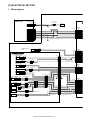
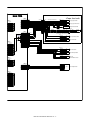
1. Wiring diagram
Main unit
Connected
to the main body
Heater harness
ELR-12V
4
AC-L(H)
F.G.
5
12
AC-N(H)
ELP-12V
4
5
12
ELR-15V
1
N.C.
2
N.C.
TXD-LCC
3
4
RXD-LCC
/DTR-LCC
5
6
/DSR-LCC
RES-LCC
7
F.G.
8
9
+5V
GND
10
+24V
11
GND
12
/TRC-LCC
13
N.C.
14
N.C.
15
ELP-15V
1
2
3
4
5
6
7
8
9
10
11
12
13
14
15
ELP-02V
1
2
MAIN PW
ELR-02V
1
2
Heater
Safty earth
Cassete detection
switch
LPISW
LCD(24V)
LCD
CN-A
PAP-12V-S
1
1
2
2
3
3
4
4
5
5
6
6
77
8
8
9
9
10 10
11 11
12 12
Main unit relay harness A3
PS-187-2V
1
2
3
CN-B
<Cassette unit>
Reverse-winding
detection switch
LWRSW
+24V
ON
LWRSW(24V)
LLM+
LLM-
Lift motor
1
2
Lower limit sensor
Paper front surface sensor
LTLLED
LTLSW
+5VR
LTLLED
LTLSW
GND
LTLS
LFAN1
GND
LTLD
+5V
SMR-03V-N
1
2
3
SMP-03V-NC
1
2
3
179228-3
SMR-04V-N SMP-04V-NC
11
2
2
3
3
4
4
PHNR-09-H
1
2
3
SMR-03V-N SMP-03V-NC
1
1
2
2
3
3
1
2
3
4
5
6
1
2
3
4
55
6
7
8
9
6
5
4
3
2
1
PHNR-09-H
9
8
7
6
4
3
2
1
PHNR-16-H
16
15
14
13
12
11
10
9
8
7
6
5
4
3
2
1
PHNR-16-H
1
2
3
4
5
6
7
8
9
10
11
12
13
14
15
16
Cassette unit side harness A3 CD
SMP-03V-NC
1
2
3
SMR-03V-N
1
2
3
SMP-03V-NC
1
2
3
SMR-03V-N
1
2
3
Cassette unit front harness A3 CD
LFAN2
4
B16B-PHDSS
LLSW(24V)
GND
GND
LIPSW(24V)
GND
LIPSW(24V)
LCD(24V)
GND
GND
LLM(+)
+24V(PS)
GND
GND
LWRSW(24V)
LLM(-)
GND
CN-C
Lowering SW PWB relay harness
Tray lock sensor
PHR-3
PHNR-06-H
LTLD
3
4
55
6
7
88
9
10
11
12
13
14
15
16
17
18
1
2
3
+5V
LPUD
GND
PHR-4
1
2
3
4
2
3
1
2
3
4
5
6
7
8
9
10
11
12
13
14
15
16
PHR-9
LRE
Lock release PWB
SNP-18V-NC
1
2
1
2
3
Lift motor encoder input
LPUD
ELP-03V
1
2
3
1
PHDR-16VS-2
1
2
3
4
5
6
7
8
9
10
11
12
13
14
15
16
PHR-3
+5VR
GND
LDD
LDD
SMR-18V-N
PS-187-3V
1
2
3
ELR-03V
1
2
3
B12B-PASK
N.C.
/TRC-LCC
RES-LCC
/DSR-LCC
/DTR-LCC
RXD-LCC
TXD-LCC
GND
GND
+5V
GND
+24V
1
2
3
4
5
6
7
8
9
6
7
9
10
11
12
13
14
15
16
17
18
1
2
3
4
5
6
7
8
9
B9B-PH-K-S
+5VR
GND
LDD
LRE
GND
+5VR
+5V
LPUD
GND
CN-D
SMR-11V-N
1
22
33
44
5
6
7
8
9
10
11
Cassette unit
rear harness A3 CD
MX-LCX3 ELECTRICAL SECTION 11 – 1
SMP-11V-NC
1
5
6
7
8
9
10
11
Cassette relay harness CD
PHDR-18VS-2
1
2
3
4
5
6
7
8
9
10
11
12
13
14
15
16
17
18
1
2
3
4
5
6
7
8
9
10
11
12
13
14
15
16
17
18
B18B-PHDSS
+5VR
LTLLED
LTLSW
GND
+5V
GND
LTLD
N.C.
24V-ICP
LTLSL
N.C.
LTLSU
24V
24V
LFAN1
LFAN2
GND
GND
MAIN PWB
<Paper feed unit>
CN-E
+5V
/LPED
GND
GND
/LUD
+5V
+24V
LPFS
+5V
GND
/LPFD
CN-A
1
2
3
4
5
6
8
9
10
11
12
B12B-PASK
N.C.
/TRC-LCC
RES-LCC
/DSR-LCC
/DTR-LCC
RXD-LCC
TXD-LCC
GND
GND
+5V
GND
+24V
B11B-PH-K-S
1
2
3
4
5
6
7
8
9
10
11
SMP-18V-NC
1
2
3
4
5
6
7
8
9
10
11
12
13
14
15
16
17
18
PHR-11
1
2
3
4
5
6
7
8
9
10
11
CN-F
ICP-N15
CN-B
1
2
3
4
5
6
7
8
9
10
11
12
13
14
15
16
B16B-PHDSS
LLSW(24V)
GND
GND
LIPSW(24V)
GND
LIPSW(24V)
LCD(24V)
GND
GND
LLM(+)
+24V(PS)
GND
GND
LWRSW(24V)
LLM(-)
GND
B20B-PHDSS
1
+24V(PS)
2
GND
GND
3
LDSW(24V)
4
5
GND
6
LDSW(24V)
7
LLSW(24V)
8
GND
GND
99
LDSW(24V)-ICP
10
LPFC
11
GND
12
GND
13
LDSW(24V)-ICP
14
15
LTRC
GND
16
GND
17
+5VR
18
LTOD
19
GND
20
PHDR-20VS-2
1
2
3
4
5
6
7
8
Paper feed side
10
11
12
13
14
15
16
17
18
19
20
SMR-18V-N
1
2
3
4
5
6
7
8
9
10
11
12
13
14
15
16
17
18
Paper feed unit harness A3
B9B-PH-K-S
+5VR
GND
LDD
LRE
GND
+5VR
+5V
LPUD
GND
SMP-03V-NC
1
2
3
1
1
1
2
2
2
3
3
3
SMP-03V-NC
SMR-03V-N
SMR-03V-N
LPED
Tray paper sensor
GND
/LUD
+5V
LUD
Tray upper limit sensor
LPFS
SMP-04V-NC
11
22
3
Paper feed solenoid
179228-3
1
+5V
2
/LPFD
3
GND
3
SMR-04V-N
LPFD
Paper feed sensor
Transport sensor relay harness A3
main harness
Transport sensor harness A3 CD
Transport sensor relay harness A3 CD
FPS-187
1 +24V
1
LDSW
Upper open/close switch
LLSW
Upper limit switch
LPFC
Paper feed clutch
LTRC
Paper transport clutch
LTOD
Main unit
communication sensor
LDSW(24V)
PS-187-3V
1 LDSW(24V)
2 NC
3 LLSW(24V)
CZHR-03V-S
1 +24V
2 N.C.
3 LPFC
CZHR-03V-S
1 +24V
2 N.C.
3 LTRC
179228-3
+5VR
1
LTOD
2
3
GND
CN-G
B5B-PH-K-S
1
+24V
2
GND
3
LPFM
4
LPFM-T
LPFM-CLK
5
PHR-5
1 +24V
2 GND1
3 LPFM
4 LPFM-T
5 LPFM-CLK
PHR-5
1
2
3
4
5
CN-D
1
2
3
4
5
6
7
8
9
10
11
12
13
14
15
16
17
18
+5V
/LPED
GND
1
1
2
2
SMP-02V-BC SMR-02V-B
CN-C
1
2
3
4
5
6
7
8
9
179228-3
1
2
3
PHR-3
1
2
3
B18B-PHDSS
+5VR
LTLLED
LTLSW
GND
+5V
GND
LTLD
N.C.
24V-ICP
LTLSL
N.C.
LTLSU
24V
24V
LFAN1
LFAN2
GND
GND
MX-LCX3 ELECTRICAL SECTION 11 – 2
LPFM
LCC transport motor
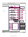
2. Block diagram
Main unit
RXD-LCC
TXD-LCC
DSR-LCC
Communication
buffer circuit
DTR-LCC
RES-LCC
TRC-LCC
Input circuit
5V
5V
Xtal
GND2
7.37MHz
+24V
24V
GND1
Onboard
writing circuit
F.G.
Communication
writing circuit
EEPROM
DOWN SW PWB
LCC tray LED(LTLLED)
LED drive
circuit
LCC tray SW(LTLSW)
Sensor
input circuit
+24V
LCC separation
auxiliary fan(FAN1)
Buffer
circuit
LCC separation
auxiliary fan(FAN2)
LDSW(24V)-ICP
LCC paper feed
clutch(LPFC)
IC protector
+24V ICP-N15
IC protector
ICP-N20
IC protector
LCC paper feed
clutch(LTRC)
LCC tray lock solenoid
Lock release(LTLSU)
Solenoid clutch drive circuit
Lock(LTLSL)
LCC paper feed solenoid(LPFS)
ICP-N15
A3-LCC P
A3-LCC
MX-LCX3 ELECTRICAL SECTION 11 – 3
+24V
24V monitor
circuit
LCC transport motor(LPFM)
LCC upper open/close
detection switch(LDSW)
LDSW(24V)-ICP
Poly switch1.1A
CPU(H8/3687)
Upper door detection
monitor circuit
LCC upper limit switch(LLSW)
Calculating section
Upper limit detection
monitor circuit
LCC illegal paper detection switch(LIPSW)
Illegal paper detection
monitor circuit
LCC cassette detection switch(LCSW)
Cassete detection
monitor circuit
LCC reverse-winding
detection switch(LWRSW)
Reverse-winding detection
monitor circuit
Rising
circuit
Lowering
circuit
Lift motor drive circuit
LCC lift motor(LLM)
Current limt
circuit
LCC paper front surface sensor(LPUD)
LCC tary upper limit sensor(LUD)
LCC tary lower limit sensor(LDD)
LCC tary paper empty sensor(LPED)
LCC transport sensor(LPFD)
Sensor input circuit
LCC main unit connection sensor(LTOD)
LCC lift motor encoder sensor(LRE)
LCC tray lock sensor(LTLD)
C PWB
C
MX-LCX3 ELECTRICAL SECTION 11 – 4
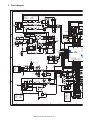
3. Circuit diagram
7
1
3
5
7
9
11
13
15
GND
LIPSW(24V)
LIPSW(24V)
GND
LLM(+)
GND
LWRSW(24V)
GND
LLSW(24V)
GND
GND
LCSW:LC7 , LCD:LCX3
GND
24V(PS)
GND
LLM(-)
VD
DAN202K
R30
10KJ x 3
R31
1SS133 ZD1
CN-B
D
D13
10KJ
TP49
1
3
5
7
9
11
13
15
D8
1SS133 ZD2
RT1N141C
R21
10KJ
NO ASSEMBLY
TP5
HZ16BP
Q7
RT1N141C
LLM(-)
D9
B16B-PHDSS-B
DAN202K
TP4
HZ16BP
2
4
6
8
10
12
14
16
LLM(+)
R20
D12
R32
Q6
D7
5
TP8
R46
10KJ
TP9
R47
10KJ
TP7
R48
10KJ
NO ASSEMBLY
R53
1MJ
TP50
1SS133 ZD3
R22
10KJ
TP6
Q5
RT1N141C
HZ16BP
IC5
1
2
3
4
TP51
Xin
VDD
Xout
S0
S1 FSOUT
LF
VSS
TP30
3
2
4
6
8
10
12
14
16
6
C15 C16 C17
FS781
1
8
R64
3.3KJ
X1
222Z/50V x 3
C30
103Z
2
CSTLS7M37G53
TP29
NO ASSEMBLY
1SS133
15KF
TP54
TP58
TP59
+5V
+5V
R17
TP2
+5V
R18
2.4KJ
R14
1KJ
4.7KJ
OUT1 Vcc
-IN1 OUT2
+IN1
-IN2
GND +IN2
8
7
6
5
R15
1KJ
Q2
C2
47uF/16V
2SD2162
R12
1KJ
E
TP55
2SD2162
E
R13
1KJ
C11 104Z/16V
C9
BA10393F
TP1
R16
TP14
TP15
1SR153-400 x 2
D6
C10
R11
0.22J(1W)
D3
C8
103Z/50V
YOBI_1
YOBI_2
LLUM
LLDM
100J
TP16
TP17
TP10
TP18
TP11
VD
1
2
3
4
10KJ
A0
Vcc
A1
WP
A3 SCL
Vss SDA
8
7
6
5
R38
R39
R40
R37
TP12
TP13
4.7KJ
4.7KJ
0J
0J
LCSW 17
LWRSW18
YOBI_1 19
N.C._I/O20
N.C._I/O21
YOBI_2 22
LLUM 23
LLDM 24
/LTLSW 25
SDA
26
SCLK 27
N.C._I/O
P36
P37
P52/WKP2
P53/WKP3
P54/WKP4
P55/WKP5/ADTRG
P10/TMOW
P11
P12
P56/SDA
P57/SCL
P74/TMRIV
P75/TMCIV
P76/TMOV
P24
P63/FTIOD0
28
/LDD
29
/LPUD 30
LTLSU 31
N.C._I/O32
CAT24WC04
C18
C19
104Z/16V
222Z/50V
+5V
CN-C
1
2
3
4
5
6
7
8
9
R1
VD
220J(1/4W)
D2
R5
4.7KJ
R7
10KJ
R4
10KJ
R74
4.7KJ
TP40
TP19
TP22
TP20
B
+5VR
GND
/LDD
LRE
GND
+5V
+5V
/LPUD
GND
P17/IRQ3/TR
P16/I
P15/I
P14/I
P72/TX
P71/RX
DSR_LCC
LTLLED
/NMI
LPFM-CLK
/LED
LFAN
DTR_LCC
/TRC_LCC
EM_P85
EM_P86
EM_P87
N.C._I/O
TXD_LCC
RXD_LCC
LTLSL
N.C._I/O
D1
DAN202K
+5V
1
2
3
4
5
6
7
8
9
IC6
H8/3687
VD
R41
R42
DAP202K
B9B-PH-K-S
C3
10KJ
10KJ
Q20
C2
C4
/LRE
NO ASSEMBLY
C34
222Z/50V
D14
DAN202K
1
222Z/50V x 3
SW1
3
T3B-SQ / JM-2W-96
+5V
D15
C22
DAP202K
VD
Q12
R45
4.7KJ
R35
4.7KJ
R44
4.7KJ
222Z/50V
TP57
10KJ
4.7KJ
4.7KJ
1KJ
4 7KJ
+24V
+5V
ICP1
ICP-N20
1
3
5
7
9
11
13
15
17
+5V
R8
R9
10KJ
R10
10KJ
Q8
220J(1/4W)
R36
R73
10KJ
10KJ
R56
R63
R62
R61
R52
CN-D
Q11
C5
222Z/50V
+5V
C6
222Z/50V
/RESET_LCC
104Z/16V
222Z/50V
2
4
6
8
10
12
14
16
18
Q9
C20
104Z/16V
R2
1KJ
Q15 RT1N141C x 2
/LTLLED
GND
GND
N.C.
/LTLSL
/LTLSU
+24V
/FAN2
GND
8
1
3
5
7
9
11
13
15
17
+5VR
/LTLSW
+5V
/LTLD
+24V-ICP
N.C.
+24V
/FAN1
GND
Q14
7
6
MX-LCX3 ELECTRICAL SECTION 11 – 5
RES_LCC
/TXD_LCC
GND
GND
+5V
+5V
/RES_LCC
/NMI
P85
P86
P87
TXD_LCC
RXD_LCC
N.C.
5
VD
1
3
5
7
9
11
13
A
RT1N141C x 3
1
2
3
4
5
6
7
8
9
10
11
12
13
14
CN-W
B14B-PHDSS-B
2
4
6
8
10
12
14
R3
1KJ
C29
C27
B18B-PHDSS-B
2
4
6
8
10
12
14
16
18
10KJ x 4
R60
R59
R58
R50
R51
2
RT1N141C
/LTLSL
/LTLSU
PB5/
PB4/
PB0/
PB1/
PB2/
PB3/
33
34
35
36
37
38
39
40
41
42
43
44
45
46
47
48
+5V
104Z/16V
P62/FTIOC0
P61/FTIOB0
NMI
P60/FTIOA0
P64/FTIOA1
P65/FTIOB1
P66/FTIOC1
P67/FTIOD1
P85
P86
P87
P20/SCK3
P21/RXD
P22/TXD
P23
P70/SCK3_2
R33
IC3
TP25
TP27
104Z/16V
+ C21
TP60
TP3
R19
510J
C24
104Z/16V
LLM(-)
LLM(+)
C
+5V
1SR153-400 x 2
B
683K/50V(2012)
C12
C
Q4
IC1
1
2
3
4
C
B
C14
473K/50V(2012)
LLDM
2SB1431 D5
TP53
TD62503
C
C
R6
TP24
1KJ
R34
C13
473K/50V(2012)
D11
TP23
D4
B
2SB1431
TP31
VD
TP28
TP26
100J
JP1
B
R55
0J
R57
R28
16
15
14
13
12
11
10
9
I1
O1
I2
O2
I3
O3
I4
O4
I5
O5
I6
O6
I7
O7
GND N.C.
R23
2.4KJ(1/4W)
R24
2.4KJ(1/4W)
IC2
1
2
3
4
5
6
7
8
R54
0J
NO ASSEMBLY
L1
MMZ1608S121AT
Q1
N.C._IN
L24VM
1SS133
15KF
R27
E
LIPSW
LPFC
LPFS
LTRC
LLUM
+24V
E
Q3
16
15
14
13
12
11
10
9
8
7
6
5
4
3
2
1
100J
R25
2.4KJ(1/4W)
47uF/35V
10KJ
R29
R26
2.4KJ(1/4W)
+ C7
47uF/35V
P35
P34
P51/WKP1
P50/WKP0
Vcc
OSC1
OSC2
Vss
TEST
RES
Vcl
X1
X2
AVcc
PB7/AN7
PB6/AN6
+ C1
D10
+5V
5
4
3
2
+5V
1
2
4
6
8
10
12
14
16
18
20
ICP2
ICP-N15
+24V
20
18
16
14
12
10
8
6
4
2
+24V
R6
10KJ
ZD4
MTZJ20BT
VD
NO ASSEMBLY
R53
1MJ
TP50
IC5
1
2
3
4
TP51
R64
3.3KJ
X1
YOBI_1
104Z/16V
YOBI_2
FS781
1
3
TP30
C25
8
7
6
5
Xin
VDD
Xout
S0
S1 FSOUT
LF
VSS
C30
103Z/50V
I1
O1
I2
O2
I3
O3
I4
O4
I5
O5
I6
O6
I7
O7
GNDCOM
PS1
RXE110
16
15
14
13
12
11
10
9
D
/LTLSU
/LPFS
/LTLSL
1SS133 x 2
2
TP29
R88
TP31
10KJ
R65
TP23
TP24
10KJ x 3
C26
47uF/16V
TP25
104Z/16V
/LPFS
Q21
D22
D23
DAN202K x 2
RT1N141C x 3
TP47
TP56
R83
N.C._IN
L24VM
LIPSW
LPFC
LPFS
LTRC
CN-E
B11B-PH-K-S
ICP3
ICP-N15
TP48
VD
+ C21
V
ZD5
R87
Q18
TP52
24
R86
10KJ x 3
VD
T
+24V
ZD6
ZD7
R79
R81
+5V
R78
220J(1/4W)
Q17
TP43
TP46
TP44
TP45
+5V
R78
+5V
R78
LC7:220J 1/4W
LCX3:JUMPER
16
15
14
13
12
11
10
9
8
7
6
5
4
3
2
1
10KJ x 4
C33 C31 C32
P35
P34
P51/WKP1
P50/WKP0
Vcc
OSC1
OSC2
Vss
TEST
RES
Vcl
X1
X2
AVcc
PB7/AN7
PB6/AN6
7
8
9
0
1
2
3
4
5
6
7
8
9
0
1
2
IC6
H8/3687
222Z/50V x 3
D24
PB5/AN5
PB4/AN4
PB0/AN0
PB1/AN1
PB2/AN2
PB3/AN3
P30
P31
P32
P33
P17/IRQ3/TRGV
P16/IRQ2
P15/IRQ1
P14/IRQ0
P72/TXD_2
P71/RXD_2
64
63
62
61
60
59
58
57
56
55
54
53
52
51
50
49
LDSW
LLSW
/LUD
/LPFD
/LPED
N.C._IN
LPFM
/LPFM-T
/LPFD1
N.C._I/O
N.C._I/O
/LTLD
/LRE
/LTOD
N.C._I/O
N.C._I/O
TP32
TP33
TP34
TP35
TP36
R66
R67
R68
R69
R70
10KJ
10KJ
10KJ
10KJ
10KJ
TP37
TP38
TP39
R71
R72
10KJ
10KJ
D26
R80
R77
R82
R84
C37
C39
C40
D25
D27
C38
NO ASSEMBLY
+5V
DAP202K x 2
TP41
TP42
R75
/LRE
10KJ
222Z/50V x 4
R85
220J(1/4W)
CN-H
3
2
1
+5V
33
34
35
36
37
38
39
40
41
42
43
44
45
46
47
48
B3B-PH-K-S
DSR_LCC
LTLLED
/NMI
LPFM-CLK
/LED
LFAN
DTR_LCC
/TRC_LCC
EM_P85
EM_P86
EM_P87
N.C._I/O
TXD_LCC
RXD_LCC
LTLSL
N.C._I/O
R89
10KJ
TP21
TP27
C41
B
R57
1KJ
VD
VD
CN-G
10KJ x 4
R60
R59
R58
R50
R43
220J(1/4W)
4.7KJ x 2
Q13
R76
R49
RT1N141C x 2
Q19
Q16
LED1
LED
Q10
D15
222Z/50V
TP57
D17
/LPFM-CLK
/LPFM-T
/LPFM
GND
LOSW(24V)
RT1N141C x 2
D19
+5V
DAN202K x 2
R56
R63
R62
R61
R52
Q8
5
4
3
2
1
5
4
3
2
1
B5B-PH-K-S
+5V
10KJ
4.7KJ
4.7KJ
1KJ
4.7KJ
C22
DAP202K
GND
/LPFD1
5VR
222Z/50V
R51
D14
DAN202K
3
2
1
+24V
TP28
TP26
VD
10KJ
TP19
TP22
TP20
40
C
DAN202K x 2
P62/FTIOC0
P61/FTIOB0
NMI
P60/FTIOA0
P64/FTIOA1
P65/FTIOB1
P66/FTIOC1
P67/FTIOD1
P85
P86
P87
P20/SCK3
P21/RXD
P22/TXD
P23
P70/SCK3_2
P36
P37
P52/WKP2
P53/WKP3
P54/WKP4
P55/WKP5/ADTRG
P10/TMOW
P11
P12
P56/SDA
P57/SCL
P74/TMRIV
P75/TMCIV
P76/TMOV
P24
P63/FTIOD0
+5V
/LPED
GND
GND
/LUD
+5V
+24V
/LPFS
+5VR
GND
/LPFD
11
10
9
8
7
6
5
4
3
2
1
Y
R55
0J
D21
HZ16BP x 3
/RESET_LCC
R54
0J
1
2
3
4
5
6
7
8
9
10
11
+24V
TD62003AP
D16
7G53
+24V(PS)
GND
GND
LLSW(24V)
GND
/LPFC
GND
/LTRC
GND
/LTOD
C23
222Z/50V
IC4
1
2
3
4
5
6
7
8
1
3
5
7
9
11
13
15
17
19
19
17
15
13
11
9
7
5
3
1
NO ASSEMBLY
CN-F
B20B-PHDSS-B
GND
LDSW(24V)
LDSW(24V)
GND
LDSW(24V)-ICP
GND
LDSW(24V)-ICP
GND
+5V
GND
+24V
Q11
+ C35
47uF/16V
D18
C36
223K/50V(1608)
+ C42
47uF/35V
D20
DAP202K x 2
C29
C27
104Z/16V
222Z/50V
C28
104Z/16V
N141C x 3
5
1
2
3
4
5
6
7
8
9
10
11
12
1
3
5
7
9
11
13
VD
CN-W
B14B-PHDSS-B
B12B-PASK
CN-A
2
4
6
8
10
12
14
S_LCC
D_LCC
D
D
V
V
S_LCC
MI
5
6
7
D_LCC
D_LCC
.
4
1
2
3
4
5
6
7
8
9
10
11
12
N.C.
/TRC_LCC
RES_LCC
/DSR_LCC
/DTR_LCC
/RXD_LCC
/TXD_LCC
GND
GND
+5V
GND
+24V
3
MX-LCX3 ELECTRICAL SECTION 11 – 6
A
2
1
LEAD-FREE SOLDER
The PWB’s of this model employs lead-free solder. The “LF” marks indicated on the PWB’s and the Service Manual mean “Lead-Free” solder.
The alphabet following the LF mark shows the kind of lead-free solder.
Example:
<Solder composition code of lead-free solder>
Lead-Free
5mm
Solder composition
code (Refer to the
table at the right.)
a
Solder composition
Solder composition code
Sn-Ag-Cu
a
Sn-Ag-Bi
Sn-Ag-Bi-Cu
b
Sn-Zn-Bi
z
Sn-In-Ag-Bi
i
Sn-Cu-Ni
n
Sn-Ag-Sb
s
Bi-Sn-Ag-P
Bi-Sn-Ag
p
(1) NOTE FOR THE USE OF LEAD-FREE SOLDER THREAD
When repairing a lead-free solder PWB, use lead-free solder thread.
Never use conventional lead solder thread, which may cause a breakdown or an accident.
Since the melting point of lead-free solder thread is about 40°C higher than that of conventional lead solder thread, the use of the
exclusive-use soldering iron is recommendable.
(2) NOTE FOR SOLDERING WORK
©
Since the melting point of lead-freeCOPYRIGHT
solder is about 220°C, which
is about
40°C higher
than that of conventional lead solder, and its soldering
XXXX
BYSHARP
CORPORATION
capacity is inferior to conventional one, it is apt to keep the soldering iron in contact with the PWB for longer time. This may cause land
separation or may exceed the heat-resistive temperature
components.
Use enough care to separate the soldering iron from the PWB when
ALLofRIGHTS
RESERVED.
completion of soldering is confirmed.
Since lead-free solder includes a greater quantity of tin, the iron tip may corrode easily. Turn ON/OFF the soldering iron power frequently.
If different-kind solder remains on the soldering iron tip, it is melted together with lead-free solder. To avoid this, clean the soldering iron
tip after completion of soldering work. No part of this publication may be reproduced,
in a retrieval
orfile
transmitted
If the soldering iron tip is discolored black stored
during soldering
work,system,
clean and
the tip within
steel wool or a fine filer.
any form or by any means, electronic, mechanical,
photocopying, recording, or otherwise, without
prior written permission of the publisher.
* Applicable to battery-operated equipment
* Applicable to battery-operated equipment
SHARP CORPORATION
Digital Document System Group
CS Promotion Center
Yamatokoriyama, Nara 639-1186, Japan
2006 June Printed in Japan