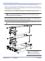
1
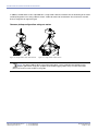
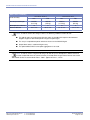
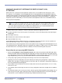
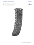
ASSEMBLY GUIDE
MG-MICA MULTIPURPOSE GRID AND ACCESSORIES
M SERIES
© 2005 Meyer Sound. All rights reserved.
MG-MICA Multipurpose Grid and Accessories Assembly Guide
The contents of this manual are furnished for informational purposes only, are subject to change without notice, and should not be construed
as a commitment by Meyer Sound Laboratories Inc. Meyer Sound assumes no responsibility or liability for any errors or inaccuracies that
may appear in this manual. Except as permitted by applicable copyright law, no part of this publication may be reproduced, stored in a
retrieval system, or transmitted, in any form or by any means, electronic, mechanical, recording or otherwise, without prior written permission
from Meyer Sound.
MICA, GuideALink and MAPP Online Pro are trademarks of Meyer Sound. Meyer Sound and QuickFly are registered trademarks of Meyer
Sound Laboratories Inc. (Reg. U.S. Pat. & Tm. Off.). All third-party trademarks mentioned herein are the property of their respective
trademark holders.
Printed in the U.S.A.
Part Number: 05.147.034.01 A
MG-MICA MULTIPURPOSE GRID AND ACCESSORIES
CONTENTS
This assembly guide provides instructions on how to safely assemble and use the MG-MICA multipurpose grid and accessories. In addition to descriptions of the MG-MICA grid’s major components, this guide will show how the components
work together with examples of common uses.
1.
Safety, Regulatory, Inspection & Maintenance Information
4
2.
The MICA GuideALink™ Rigging System
6
MICA GuideALinks
6
The MG-MICA Multipurpose Grid
8
3.
Attaching the Grid Links
Front and Rear Positions
10
10
Using the MG-MICA Multipurpose Grid to Fly MICA™ Loudspeaker Arrays
11
MG-MICA Grid with MICA Loudspeakers in Forward Position for Maximum Downtilt
MG-MICA Grid with MICA Loudspeakers in Rearward Position for Maximum Uptilt
MG-MICA Pickup Configurations
Common Pickup Configurations Using Two Motors
Common Pickup Configurations Using One Motor
Load Ratings Overview
Prerequisite Conditions
Using MAPP Online Pro™ to Determine the Center of Gravity (COG) of the Array
11
12
13
13
14
15
15
17
5.
Using the MG-MICA Grid to Ground-Stack MICA Loudspeaker Arrays
22
6.
600-HP Rigging
24
4.
600-HP to 600-HP
Flown 600-HP to MICA
Ground-Stacked 600-HP to MICA
7.
8.
9.
25
27
28
Using the MG-MICA with 600-HP Subwoofers
29
Flown Configuration
Ground-Stacked Configuration
29
29
Accessories for the MG-MICA Grid, MICA, and 600-HP
31
MGCP-MICA Center Point Rigging Beam
MGCP-MICA Installation Procedure
MTF-MILO/MICA Transition Frame
MDTL-MICA Downtilt Link
MDTL-MICA with MG-MICA Grid
MDTL-MICA with 600-HP
MCF-MICA Caster Frame
MCF-MICA for 600-HP
31
31
33
34
34
35
37
39
Assembling an Array of MICA Loudspeakers to the MG-MICA Grid
41
Meyer Sound Laboratories Inc.
www.meyersound.com
T: +1 510 486.1166
F: +1 510 486.8356
PN: 05.147.034.01 A
Page 3 of 44
MG-MICA MULTIPURPOSE GRID AND ACCESSORIES
1. SAFETY, REGULATORY, INSPECTION & MAINTENANCE INFORMATION
Please read this Statement carefully and in its entirety. It contains important information regarding safety issues, including
guidelines for general safe use of rigging systems as well as advisories on government regulations and liability laws.
SCOPE OF THIS MANUAL
Although this manual contains much useful information on rigging in general, it does not claim to be a comprehensive
resource on the subject. This manual assumes that the owners and/or users of a QuickFly® system are knowledgeable and
experienced in the areas of rigging and flying loudspeaker systems. MANY ISSUES OF CRUCIAL CONCERN, SUCH AS
THE DETERMINATION OF APPROPRIATENESS AND CONDITION OF VENUE RIGGING POINTS, CANNOT BE ADDRESSED
HERE. THEREFORE, THE USER MUST ASSUME ALL RESPONSIBILITY FOR THE APPROPRIATE USE OF QUICKFLY SYSTEMS IN ANY PARTICULAR LOCATION OR CIRCUMSTANCE.
The suspension of large, heavy objects in public places is subject to numerous laws and regulations at the national/federal,
state/provincial, and local levels. This manual does not address the specifics of any such applicable laws and government
regulations. This manual details procedures and practices consistent with those generally acknowledged as allowable and
safe in the United States. However, the user must assume responsibility for making sure that use of any QuickFly system and
its components in any particular circumstance or venue conforms to all applicable laws and regulations in force at the time.
LOAD RATINGS AND SPECIFICATIONS
Long-term safe operation is a central concern in the design and manufacture of any rigging/flying system. Meyer Sound has
taken great care in material selection and component design. After manufacture, all load-critical system components are
individually inspected.
All load ratings and other specifications given in this manual are the result of accepted engineering practice and careful testing. However, such specifications and ratings are subject to change. USERS SHOULD CHECK THE QUICKFLY SECTION OF
THE MEYER SOUND WEB SITE AT
http://www.meyersound.com
OR CONTACT TECHNICAL SUPPORT AT REGULAR INTERVALS TO CHECK FOR UPDATED OR REVISED INFORMATION.
REGULATORY COMPLIANCE
The design and safe working load (SWL) ratings of the QuickFly system are intended to be in compliance with all known
regulatory statutes currently applicable in the United States. Unless otherwise specified, all working loads are based on either
a 5:1 or 7:1 safety factor. However, as noted above, there are wide variations internationally in the regulations and practices
applying to suspension of sound systems in public places. Although regulations in the United States are generally among the
most stringent, safety codes may be even stricter in a few localities (such as those highly prone to earthquakes). In addition,
applicable safety codes are open to interpretation: Government officials in one location may have a stricter interpretation than
another local official, even when operating under the same regulations and in the same legal jurisdiction.
CONSEQUENTLY, USERS OF QUICKFLY RIGGING SYSTEMS SHOULD BE PREPARED TO TAKE ADDITIONAL SAFETY ASSURANCE MEASURES BEYOND THOSE OUTLINED IN THIS MANUAL. IN ALL CASES, IT IS THE RESPONSIBILITY OF THE
USER TO MAKE CERTAIN THAT ANY MEYER SOUND LOUDSPEAKER SYSTEM IS SUSPENDED IN ACCORDANCE WITH
ALL APPLICABLE NATIONAL/FEDERAL, STATE/PROVINCIAL, AND LOCAL REGULATIONS.
SAFETY RESPONSIBILITIES “ABOVE THE HOOK”
In most touring applications of rigging systems, the touring sound provider is normally responsible for ensuring the safety of
the suspension system only below the attachment point. The safety and suitability of the attachment point is generally seen
as the responsibility of the venue owner or operator. However, this distinction (“above the hook” versus “below the hook”)
can be open to interpretation. Touring system operators should double-check to make certain that attachment points are
approved and suitably load rated, and that the points used are those identified as such by the venue owner or operator. AS
AN EXTRA PRECAUTION, CAREFUL INSPECTION OF THE ATTACHMENT POINTS IS ADVISED BEFORE FLYING, PARTICULARLY IN OLDER VENUES OR THOSE HOSTING FREQUENT EVENTS USING LARGE SOUND AND LIGHTING SYSTEMS.
In any case, Meyer Sound QuickFly systems are intended only for suspension from approved rigging points, each known to
have ample SWL margins for the system components suspended below them.
Meyer Sound Laboratories Inc.
www.meyersound.com
T: +1 510 486.1166
F: +1 510 486.8356
PN: 05.147.034.01 A
Page 4 of 44
MG-MICA MULTIPURPOSE GRID AND ACCESSORIES
INSPECTION AND MAINTENANCE
The Meyer Sound QuickFly systems are an assembly of mechanical devices, and are therefore subject to wear and tear over
prolonged use, as well as damage from corrosive agents, extreme impact, or inappropriate use.
BECAUSE OF THE SAFETY ISSUES INVOLVED, USERS MUST ADOPT AND ADHERE TO A SCHEDULE OF REGULAR INSPECTION AND MAINTENANCE. IN TOURING APPLICATIONS, KEY COMPONENTS MUST BE INSPECTED BEFORE EACH
USE. Such inspection includes examination of all load-bearing components for any sign of undue wear, twisting, buckling,
cracking, rusting, or other corrosion. In regard to rust and corrosion, the main components of a QuickFly system are either
protected by an exterior coating or made from stainless steel, which is impervious to rust and resistant to most corrosive
fluids. Nevertheless, normal use and shipping vibrations can wear through the protective coatings, and extremely corrosive
fluids (such as battery acid) can cause severe damage with prolonged exposure even to protected parts. Particular attention should be given to screws, bolts, and other fasteners to make certain the fittings are tight and secure. Metal seams and
welds should be examined for any sign of separation or deformation. Meyer Sound strongly recommends that written documentation be maintained on each QuickFly system, noting date of inspection, name of inspector, points of system checked,
and any anomalies discovered.
Annual Comprehensive Examination and Test Program
In addition to routine checks on the road for touring systems, Meyer Sound also recommends a careful, comprehensive
system examination and testing “at home” in the warehouse or other appropriate location at regular intervals. Such at home
examinations and tests should occur at least once a year, and should include a careful inspection of each component under
ideal lighting conditions, and then a final comprehensive check of the entire system after it has been flown.
If any anomalies or defects are discovered that could possibly affect the safety or integrity of the system, affected parts or
subsystems should be replaced in their entirety before that part of the system is flown again.
REPLACEMENT PARTS
Any component found to be defective, or any safety-related component you even suspect might be defective, should be replaced with the equivalent, approved part. Parts specific to a QuickFly system should be ordered directly from Meyer Sound.
No attempt should be made to substitute what appears to be equivalent or “mostly the same” generic replacements. Some
parts used in QuickFly systems are identical to those used in other rigging applications. To the best of our knowledge, most
of these suppliers are reputable and their products are reliable. However, Meyer Sound has no way of assuring the quality of
products made by these various suppliers. Therefore, Meyer Sound is not responsible for problems caused by components
that were not supplied by Meyer Sound.
TRAINING
QuickFly systems are relatively straightforward and easy to use. However, they should only be used by persons trained in the
use of loudspeaker rigging systems who have mastered key points of assembly, rigging and flying. Users should read this
manual in its entirety before attempting to deploy any QuickFly system. You may make additional copies of this manual as
necessary for in-house use; copies may not be made for any other purpose.
CAUTION: All Meyer Sound products must be used in accordance with local, state, federal and
industry regulations. It is the owner’s and/or user’s responsibility to evaluate the reliability of any
rigging method for their application. Rigging should be carried out only by experienced professionals.
CAUTION: Always use properly rated rigging hardware.
CAUTION: It is important to inspect rigging hardware regularly and replace worn or damaged
components immediately.
Meyer Sound Laboratories Inc.
www.meyersound.com
T: +1 510 486.1166
F: +1 510 486.8356
PN: 05.147.034.01 A
Page 5 of 44
MG-MICA MULTIPURPOSE GRID AND ACCESSORIES
2. THE MICA™ GUIDEALINK™ RIGGING SYSTEM
MICA loudspeakers feature Meyer Sound’s QuickFly® rigging system with rugged, reliable and simple components.
QuickFly facilitates deploying the loudspeakers in a variety of applications. MICA is designed to be rigged using
professional components, and its custom front and rear GuideALinks rigidly couple the individual MICA enclosures for
flying, stacking, or transporting in stacks while still in various splayed positions.
MICA GUIDEALINKS
MICA’s captive QuickFly rigging hardware features rigid GuideALinks contained within recessed guides in the bottom
front and rear corners of the enclosure. A slot and convenient pinned knob allow each link to be moved and pinned for
arraying and storage. In normal use, the front links are used as the pivot point, and the splay between enclosures is
introduced with the rear links.
Front
Rear
The MICA GuideALink (below left) has two rows with angles. The MICA frame includes engraved angles for the rear
GuideALink (right). The rear links permit 10 splay angles between 0 and 6 degrees for optimum acoustical performance. These angles are: 0º, 0.5º, 1º, 1.5º, 2º, 2.5º, 3º, 4º, 5º, and 6º.
First Row
0º
0.5 º
1º
1.5 º
2º
0 .5 1 1.5
2
2.5 3 4 5
6
First Row
Angles
Second Row
Angles
Second Row
6º
Meyer Sound Laboratories Inc.
www.meyersound.com
5º4º
T: +1 510 486.1166
F: +1 510 486.8356
3º
2.5 º
PN: 05.147.034.01 A
Page 6 of 44
MG-MICA MULTIPURPOSE GRID AND ACCESSORIES
CAUTION: As part of the regular inspection and maintenance procedure for MICA loudspeakers, check
each of the captive GuideALink pins to ensure that they are tight by turning them counterclockwise by
hand. If a pin turns, it must be reset into the link using Loctite 290, and be allowed to cure for 48 hours and
retested before the loudspeaker is flown.
The front links may be set in two different positions:
■ 0°: This is the standard position (below left) and it is used to achieve splay angles between 0 and 6 degrees (adjusted on the rear) for optimal acoustical performance.
■ 7°: This is the extended position (below right) to add 7 degrees to the angles set on the rear link. These extended
angles (7 to 13 degrees) can be use to extend the coverage or to create a break in high frequencies of the array, for
example, to miss balcony fronts and other architectural obstacles.
NOTE: Optimal
acoustical
performance for MICA
is achieved by using
angles between 0 and
6 degrees in a MICA
array; use extended
angles (7 to 13
degrees) with caution
and only if necessary.
The rigid connections created by the QuickFly rigging hardware allow easy adjustment of the array tilt, often eliminating the need for pull-back straps in flown configurations.
NOTE: The numeric designations on the MICA rigging and the actual achieved angles are equivalent
when one MICA loudspeaker is connected to another (for example, setting the front link at 0 and the
rear link at 4 achieves a 4-degree downtilt of the lower enclosure relative to the upper). These are relative
angles between the two enclosures. How they relate to the floor, stage, and seating angles in the venue depends on the orientation of the grid, the other angles already set by the loudspeakers in the array above them,
whether they are used with the MG-MICA grid in a ground-stacked configuration, and other factors. Use
MAPP Online Pro to determine the actual angles and coverage pattern of the array.
Meyer Sound Laboratories Inc.
www.meyersound.com
T: +1 510 486.1166
F: +1 510 486.8356
PN: 05.147.034.01 A
Page 7 of 44
MG-MICA MULTIPURPOSE GRID AND ACCESSORIES
3. THE MG-MICA MULTIPURPOSE GRID
The MG-MICA multipurpose grid allows multiple MICA compact high-power curvilinear array loudspeakers to be flown
or ground-supported in numerous configurations. In addition, the MG-MICA grid can be used with 600-HP subwoofers
that have been fitted with MRF-600 rigging frames.
In flown configurations, the first MICA loudspeaker in the array is always connected to the MG-MICA grid at the 0°
position. The up and down tilt of the MG-MICA and the complete array hung underneath can additionally be adjusted
using chain motors, or differing lengths of steel or span set.
List of Contents: MG-MICA Multipurpose Grid Kit (Part # 40.147.034.01)
Required for use with MICA loudspeaker(s)
Meyer Sound Laboratories Inc.
www.meyersound.com
Qty
Part Number
Description
1
40.147.034.01
MG-MICA Multipurpose Grid
2
61.147.040.01
MICA Grid Link Front
2
61.147.042.01
MICA Grid Link Rear
8
134.023
3/8" x 1.5" Quick-Release Pin
(Red button and lanyard)
4
124.078
Leveling Foot
T: +1 510 486.1166
F: +1 510 486.8356
PN: 05.147.034.01 A
Page 8 of 44
MG-MICA MULTIPURPOSE GRID AND ACCESSORIES
MG-MICA Multipurpose Grid Dimensions and Weight:
41.98
[1066.20mm]
6.55
[166.28mm]
35.00
[889.00mm]
20.99
[533.10mm]
4.99
[126.70mm]
5.00
[127.00mm]
32.00
[812.80mm]
MG-MICA Multipurpose Grid Weight: 113.5 lbs (51.4 kg)
Meyer Sound Laboratories Inc.
www.meyersound.com
T: +1 510 486.1166
F: +1 510 486.8356
PN: 05.147.034.01 A
Page 9 of 44
MG-MICA MULTIPURPOSE GRID AND ACCESSORIES
ATTACHING THE GRID LINKS
Please note that the front and rear links are different. The rear link is wider than the front.
Also, note that in the rear link the spacing between the two end holes and the center hole is not identical; the shorter
distance should go up into the grid in order to pin correctly. The arrow stamped on the link indicates which way goes
into the grid.
CAUTION: The front and
rear grid links are of different widths, and should not be
substituted for each other. The
rear link is wider than the front.
CAUTION: Always use two
red button pins (3/8" x 1.5")
to secure each grid link to the
MG-MICA. These pins have lanyards
that allow them to be attached to
and remain with the MG-MICA grid.
Avoid using the blue button pins
(3/8" x 1.125") since they are shorter
and will not lock in place.
Red button pins
FRONT AND REAR POSITIONS
The MG-MICA grid allows you to fly MICA loudspeakers in two positions with respect to the grid. Two sets of link positions are provided, labeled Front (and Rear) Link, Maximum Uptilt and Front (and Rear) Link, Maximum Downtilt. Select
the appropriate set of holes on each side of the grid, and pin the front and rear grid links in place with two quick-release pins each.
Once the links are attached, they can remain with the grid as it is removed and transported in touring applications. By
pulling the lower quick-release pins, the links can be rotated clockwise into the grid, and then re-pinned in the stowed
position (when they are in the Maximum Uptilt position). Alternately, the grid can remain connected to the top MICA
loudspeaker and be transported with that stack using the MCF-MICA caster frame.
Meyer Sound Laboratories Inc.
www.meyersound.com
T: +1 510 486.1166
F: +1 510 486.8356
PN: 05.147.034.01 A
Page 10 of 44
MG-MICA MULTIPURPOSE GRID AND ACCESSORIES
4. USING THE MG-MICA MULTIPURPOSE GRID TO FLY MICA LOUDSPEAKER ARRAYS
MG-MICA GRID WITH MICA LOUDSPEAKERS IN FORWARD POSITION FOR
MAXIMUM DOWNTILT
MICA loudspeakers can be connected to the MG-MICA grid in the “forward” position in order to obtain the maximum
amount of downtilt for the array. The front and rear links are pinned to the grid on both sides in the positions labeled
“MG-MICA FRONT LINK Maximum Downtilt” and “MG-MICA REAR LINK Maximum Downtilt”. The downtilt of the
MG-MICA and the complete array hung underneath can be adjusted using chain motors, or differing lengths of steel or
span set.
CAUTION: Always use two red button pins (3/8" x 1.5") to secure each grid link to the MG-MICA. Avoid
using the blue button pins (3/8" x 1.125") since they are shorter and will not lock in place.
Follow the labeling on the grid to orient the loudspeakers; a large arrow on each side is labeled Front. Attach the top
MICA enclosure to the grid links with one 3/8" x 1.125" quick-release pin (with blue release button; part #134.021)
per link.
SAFETY WARNINGS!
1. Always use two quick release pins on each MG-MICA link.
2. DO NOT use ground-stack holes for flying points.
MICA / 600-HP
REAR LINK
Ground-Stacked
Position
Stowed
Position
MG-MICA REAR LINK
Maximum Uptilt
MICA / 600-HP
FRONT LINK
Ground-Stacked
Position
FRONT
MG-MICA REAR LINK
Maximum Downtilt
Stowed
Position
MG-MICA FRONT LINK
Maximum Uptilt
MG-MICA
MG-MICA FRONT LINK
Maximum Downtilt
Link Positions for Maximum Downtilt
CAUTION: The
front and rear
grid links are of different
widths, and should not be
substituted for each other.
The rear link is wider than
the front.
CAUTION: The
leveling feet must
always be detached from
the MG-MICA grid before
flying a system. Unscrew
the entire assembly,
including the threaded leg,
and remove completely.
Meyer Sound Laboratories Inc.
www.meyersound.com
T: +1 510 486.1166
F: +1 510 486.8356
PN: 05.147.034.01 A
Page 11 of 44
MG-MICA MULTIPURPOSE GRID AND ACCESSORIES
MG-MICA GRID WITH MICA LOUDSPEAKERS IN REARWARD POSITION FOR MAXIMUM UPTILT
MICA loudspeakers can be connected to the MG-MICA grid in the “rearward” position in order to obtain the maximum
amount of uptilt for the array. The front and rear links are pinned to the grid on both sides in the positions labeled
“MG-MICA FRONT LINK Maximum Uptilt” and “MG-MICA REAR LINK Maximum Uptilt”. The uptilt of the MG-MICA
and the complete array hung underneath can be adjusted using chain motors, or differing lengths of steel or span set.
Follow the labeling on the grid to orient the loudspeakers; a large arrow on each side is labeled Front. The first MICA is
pinned to the grid at 0 degrees using the provided grid links.
CAUTION: Always use two 3/8" x 1.5" quick-release pins (with red release button; part #134.023) for
each link in the provided holes.
Attach the top MICA enclosure to the grid links with one 3/8" x 1.125" quick-release pin (with blue release button; part
#134.021) per link.
SAFETY WARNINGS!
1. Always use two quick release pins on each MG-MICA link.
2. DO NOT use ground-stack holes for flying points.
MICA / 600-HP
REAR LINK
Ground-Stacked
Position
Stowed
Position
MG-MICA REAR LINK
Maximum Uptilt
MICA / 600-HP
FRONT LINK
Ground-Stacked
Position
FRONT
MG-MICA REAR LINK
Maximum Downtilt
Stowed
Position
MG-MICA FRONT LINK
Maximum Uptilt
MG-MICA
MG-MICA FRONT LINK
Maximum Downtilt
Link Positions for Maximum Uptilt
CAUTION: The
front and rear
grid links are of different
widths, and should not
be substituted for each
other. The rear link is
wider than the front.
TIP: When the
links are inserted
in the rear position they
can be stowed inside the
MG-MICA for transportation.
SAFETY WARNINGS!
1. Always use two quick release pins on each MG-MICA link.
2. DO NOT use ground-stack holes for flying points.
MICA / 600-HP
REAR LINK
Ground-Stacked
Position
Stowed
Position
MG-MICA REAR LINK
Maximum Uptilt
MICA / 600-HP
FRONT LINK
Ground-Stacked
Position
FRONT
MG-MICA REAR LINK
Maximum Downtilt
Stowed
Position
CAUTION: The leveling feet must always be detached from the MG-MICA grid before flying a system.
Unscrew the entire assembly, including the threaded leg, and remove completely.
Meyer Sound Laboratories Inc.
www.meyersound.com
T: +1 510 486.1166
F: +1 510 486.8356
PN: 05.147.034.01 A
Page 12 of 44
MG-MICA FRONT LINK
Maximum Uptilt
MG-MICA MULTIPURPOSE GRID AND ACCESSORIES
MG-MICA PICKUP CONFIGURATIONS
The MG-MICA grid can accommodate a variety of pick-up configurations using its six pickup points – three on each
side of the grid. When possible it is recommended to use front and rear pick up points in order to be able to change
the tilt of the grid and the array by using the front and rear motors.
NOTE: The design of the MG-MICA allows the use of any pickup configuration without affecting the
load rating.
It is also possible to bridle between pickup points to give better stability to the grid compared to a single point per side.
CAUTION: If a bridle is used between pick-up points on the MG-MICA, the angle of the bridle at the
apex should not be greater than 90 degrees to avoid increasing the load on the bridles and damaging
the grid.
Common pickup configurations using two motors:
Figure 4.1. Two points, front and rear
Figure 4.2. Three points, front bridle
Figure 4.3. Three points, rear bridle
CAUTION:
Always use
properly rated rigging
hardware. The use of
3/4” shackles for the
MG-MICA grid’s pick-up
points is recommended.
Figure 4.4. Four points, front and rear bridle
Meyer Sound Laboratories Inc.
www.meyersound.com
Figure 4.5. Four points, front and rear bridles on sides
T: +1 510 486.1166
F: +1 510 486.8356
PN: 05.147.034.01 A
Page 13 of 44
MG-MICA MULTIPURPOSE GRID AND ACCESSORIES
In addition, the MG-MICA can be suspended from a single motor. However, limitations like the load rating of the motor
and the pickup point in the ceiling “above the hook” need to be taken into consideration. Also, it becomes more difficult to change the tilt angle of the grid.
Common pickup configurations using one motor:
Figure 4.6. Single motor, center front and rear
Figure 4.7. Single motor, to four corners
NOTE: The optional MGCP-MICA center point rigging beam can be installed on the MG-MICA multipurpose grid to allow single pick-up points to be used for rigging a MICA array. For more information
please see the Accessories chapter in this guide.
Meyer Sound Laboratories Inc.
www.meyersound.com
T: +1 510 486.1166
F: +1 510 486.8356
PN: 05.147.034.01 A
Page 14 of 44
MG-MICA MULTIPURPOSE GRID AND ACCESSORIES
LOAD RATINGS OVERVIEW
All of the load ratings in this assembly guide take the following into consideration:
Prerequisite Conditions
The following conditions must be met to achieve the load ratings shown in Tables 1, 2 and 3:
■ Any combination of pick-up points can be used. If a bridle is used between pick-up points on the MG-MICA, the
angle of the bridle at the apex is no greater than 90 degrees.
■ The optional MGCP-MICA center point rigging beam is not used.
■ The tilt of the grid must be no larger than the one achieved by the natural rotation of the array or the limit described
in each table.
■ The array is not pulled from points other than the ones on the MG-MICA grid and no pull-back motor should be
used for tilting the array.
■ The weight of the MG-MICA grid itself has not been included (unless it is noted). These tables rate the grid. For
pick-up points and/or motors where the grid will be supported, the weight of the grid needs to be added – 113.5
lbs (51.4 kg).
■ The maximum number of MICA loudspeakers that may be hung in each configuration is based on the MICA weight
of 155 lbs (70.3 kg) to give some margin and/or allow the use of the optional rain hood with respect of the 150 lbs
published specification.
■ The load ratings and maximum weights allowed regard the MG-MICA grid and flown loudspeakers as a system,
including links and pins. Thus, the maximum stress point could change from one element to another in the system.
CAUTION: Using a bridle leg shorter than the recommended length for each configuration will reduce
the load rating and may damage the MG-MICA grid.
CAUTION: Always use properly rated rigging hardware. The use of 3/4" shackles for the MG-MICA
grid’s pick-up points is recommended.
With the use of transition accessories, you can also integrate other M Series loudspeakers, to form combined arrays.
CAUTION: The weight of any additional items hung with the array, such as downfill loudspeakers and
transition accessories and cable, must be considered when calculating maximum load.
The load rating of the MG-MICA depends on two main factors:
■ Where on the grid the center of gravity (COG) of the array underneath falls.
■ The grid tilt angle.
The maximum grid tilt angle depends on whether the array is connected to the grid in the front flown or rear flown
configuration.
Meyer Sound Laboratories Inc.
www.meyersound.com
T: +1 510 486.1166
F: +1 510 486.8356
PN: 05.147.034.01 A
Page 15 of 44
MG-MICA MULTIPURPOSE GRID AND ACCESSORIES
Table 1. Basic Load Rating
Front Flown Position
Factor of Safety
Total Suspended Weight
MICA Equivalent Cabinets
Maximum Grid Tilt
Rear Flown Position
FS5
FS7
FS5
FS7
2480 lbs
(1,127 kg)
1860 lbs
(845 kg)
2480 lbs
(1,127 kg)
1860 lbs
(845 kg)
16
12
16
12
-40º to +45º
-40º to +45º
-34º to +45º
-34º to +45º
NOTE: In order to achieve the ratings in Table 1, the following conditions need to be met:
■
The grid tilt angle can not be greater than the angles in the table with respect to the horizontal.
Negative angles are downtilt and positive angles are uptilt angles.
■
The array is not pulled from points other than the ones on the MG-MICA grid.
■
No pull-back motor is used for tilting the array.
■
The optional MGCP-MICA center point rigging beam is not used.
NOTE: In order to achieve a higher load rating to be able to fly more loudspeakers, MAPP Online Pro
must be used to find where the Center of Gravity is located within the grid. Please refer to next section
about MAPP Online Pro and the Grid’s Zones. Table 1 applies for Zone 1, 2 and 3.
Meyer Sound Laboratories Inc.
www.meyersound.com
T: +1 510 486.1166
F: +1 510 486.8356
PN: 05.147.034.01 A
Page 16 of 44
MG-MICA MULTIPURPOSE GRID AND ACCESSORIES
USING MAPP ONLINE PRO TO DETERMINE THE CENTER OF GRAVITY (COG)
OF THE ARRAY
MAPP Online Pro is a powerful acoustical prediction software that is an invaluable tool when designing a system.
This software is a cross-platform, Java-based application for accurately predicting the coverage pattern, frequency
response, impulse response, and maximum SPL output of single or arrayed Meyer Sound loudspeakers. MAPP Online
Pro facilitates configuring arrays and, optionally, defines the environment in which they will operate — including air
temperature, pressure, and humidity, as well as the location and composition of walls. You can find MAPP Online at:
www.meyersound.com/products
NOTE: In order to use MAPP Online Pro, you will need to register by clicking “Apply for MAPP Online”
on the Web site listed above. After registration and upon approval, an e-mail will be sent to you with
a user name and password along with the address for the Web site where you can download MAPP Online.
Online instructions will guide you through the download and setup process.
In addition, MAPP Online Pro displays a wealth of information related to the rigging of the system:
■ Location of the MICA’s array center of gravity. This information is critical in the determination of the load rating of
the MG-MICA.
■ Total weight of the array.
■ Distribution of the load on the front and rear points.
■ Height and depth of the array.
Use the following procedures in MAPP Online Pro as you design the array and verify that it meets the conditions for
the desired load ratings in Tables 2 and 3, on pages 19 and 20 of this document.
Once the MICA array has been designed from the acoustical point of view, the rigging information displayed on the “Insert Loudspeaker System” dialog box needs to be compared to the conditions in Tables 2 and 3. This will give information about whether the use of the grid under those conditions will meet the load rating and safety factor.
Please follow the next steps using MAPP Online Pro:
1. Open the dialog Configure > Insert Loudspeaker System and create the array below the MG-MICA grid. Select
the MICA Forward or MICA Rearward grid position, depending on whether more downtilt or more uptilt is desired
as a starting place. Insert the necessary quantity of loudspeakers, set the initial splay angles, and set the initial grid
height and positioning. If necessary, consult the MAPP Online Pro manual for further information.
2. Change splay angles, grid angle and height until the design meets the acoustical requirements.
3. Depending on the array configuration, the Center of Gravity line will be passing through Zone 1 (Green), Zone 2
(Yellow), Zone 3 (Orange), or completely behind or in front of the grid. This information is displayed at the bottom of
the Insert Loudspeaker System dialog box.
4. Consult Tables 2 and 3 to determine the maximum load (number of enclosures) permissible for a 5:1 or 7:1 safety
factor for each zone.
5. If the conditions (Zone and tilt angle) are not met, the array configuration needs to be changed until the conditions
are met.
6. Click the Select button, click on the array to select it, and then go to the Edit Loudspeaker System dialog. You can
make changes to the splay angles, grid angle and trim height and configuration (front or rear) until the grid angle
and COG falls in a zone needed to meet the load ratings needed for the particular design.
Meyer Sound Laboratories Inc.
www.meyersound.com
T: +1 510 486.1166
F: +1 510 486.8356
PN: 05.147.034.01 A
Page 17 of 44
MG-MICA MULTIPURPOSE GRID AND ACCESSORIES
In order to give a visual representation and help to make modifications to the array’s configuration, the COG and where
it falls in the grid can be displayed in the sound field.
Please follow the next steps to see the COG graphically displayed::
1. If not active, Go to View > Array COG (Center of Gravity) and place a check mark next to it. You will see a magenta line that goes from the center of gravity of the array to the top of the sound field. Refer to Figure 4.8.
2. Click the Zoom button along the top right of the Sound Field, and left-click and hold while drawing a box around
the top of the grid. You will see the three Zones marked in different colors Zone 1 (Green), Zone 2 (Yellow), Zone 3
(Orange). Refer to Figure 4.9.
3. As you change the splay and grid angle, check the results by zooming into the top of the grid and/or checking the
zone information in Center of Gravity in the table at the bottom of Edit Loudspeaker System.
Repeat until the conditions needed to meet the load rating and safety factor requirements are met.
Zone 3
Zone 3
Zone 2
Zone 2
Zone 1
Figure 4.9. MG-MICA grid’s zones (zoomed view)
Figure 4.8. Center of Gravity displayed on the sound field
(vertical magenta line)
Meyer Sound Laboratories Inc.
www.meyersound.com
T: +1 510 486.1166
F: +1 510 486.8356
PN: 05.147.034.01 A
Page 18 of 44
MG-MICA MULTIPURPOSE GRID AND ACCESSORIES
Table 2. Load Rating if Center of Gravity falls in Zone 2
Front Flown Position
Factor of Safety
Total Suspended Weight
MICA Equivalent Cabinets
Maximum Grid Tilt
Rear Flown Position
FS5
FS7
FS5
FS7
3,355 lbs
(1,522 kg)
2,580 lbs
(1,170 kg)
3,355 lbs
(1,522 kg)
2,580 lbs
(1,170 kg)
21
16
21
16
-30º to +30º
-30º to +30º
-30º to +20º
-30º to +20º
NOTE: In order to achieve the ratings in Table 2, the following conditions need to be met:
■
The grid tilt angle cannot be greater than the angles in the table with respect to the horizontal.
Negative angles are downtilt and positive angles are uptilt angles.
■
The array is not pulled from points other than the ones on the MG-MICA grid.
■
No pull-back motor is used for tilting the array.
■
The optional MGCP-MICA center point rigging beam is not used.
■
The center of gravity of the array must be located in Zone 2 (or Zone 1). MAPP Online Pro
must be used to find out this information.
Figure 4.10. Example of a COG in Zone 2
Figure 4.11. Zone 2 Center of Gravity in the Edit Loudspeaker Systems dialog
Meyer Sound Laboratories Inc.
www.meyersound.com
T: +1 510 486.1166
F: +1 510 486.8356
PN: 05.147.034.01 A
Page 19 of 44
MG-MICA MULTIPURPOSE GRID AND ACCESSORIES
Table 3. Load Rating if Center of Gravity falls in Zone 1
Front Flown Position
Factor of Safety
Total Suspended Weight
MICA Equivalent Cabinets
Maximum Grid Tilt
Rear Flown Position
FS5
FS7
FS5
FS7
3875 lbs
(1,761 kg)
3410 lbs
(1550 kg)
3875 lbs
(1,761 kg)
3410 lbs
(1550 kg)
25
22
25
22
-4º to +4º
-4º to +4º
-4º to +4º
-4º to +4º
NOTE: In order to achieve the ratings in Table 3 (25 MICA loudspeakers with a 5:1 safety factor or 22
MICA loudspeakers with a 7:1 safety factor ), the following conditions need to be met:
■
The grid tilt angle cannot be greater than the angles in the table with respect to the horizontal.
Negative angles are downtilt and positive angles are uptilt angles.
■
The array is not pulled from points other than the ones on the MG-MICA grid.
■
No pull-back motor is used for tilting the array.
■
The optional MGCP-MICA center point rigging beam is not used.
■
The center of gravity of the array must be located in Zone 1. MAPP Online Pro must be used to
find out this information.
OR
Loads must be monitored using load cell sensors to show that the total rigging load at the front or
rear of the grid does not exceed 2541 lbs (1155 kg) for 5:1 safety factor or 1815 lbs (825 kg) for
7:1 safety factor.
Meyer Sound Laboratories Inc.
www.meyersound.com
T: +1 510 486.1166
F: +1 510 486.8356
PN: 05.147.034.01 A
Page 20 of 44
MG-MICA MULTIPURPOSE GRID AND ACCESSORIES
Figure 4.12. Example of a COG in Zone 1
Figure 4.13. Zone 1 COG showing array
Figure 4.14. Zone 1 Center of Gravity in the Edit Loudspeaker Systems dialog
Meyer Sound Laboratories Inc.
www.meyersound.com
T: +1 510 486.1166
F: +1 510 486.8356
PN: 05.147.034.01 A
Page 21 of 44
MG-MICA MULTIPURPOSE GRID AND ACCESSORIES
5. USING THE MG-MICA GRID TO GROUND-STACK MICA LOUDSPEAKER ARRAYS
In addition to its suspending capabilities, the MG-MICA grid forms a secure base for ground-stacking when the leveling feet are installed. For ground-stacking, secure the GuideALinks in the bottom MICA enclosure to the MG-MICA grid
using the red button 3/8" x 1.5" quick-release pins.
Use the link positions in the grid marked MICA / 600-HP Front Link Ground-Stacked Position and MICA / 600-HP Rear
Link Ground-Stacked Position. Pin additional MICA loudspeakers at the desired splay angles to form the array.
NOTE: Up to six (6) MICA loudspeakers can be easily ground-stacked on the MG-MICA grid. Because
of the increased difficulty of stacking more than this quantity, as well as for safety reasons, avoid
ground-stacking more than six MICA loudspeakers.
When the MICA loudspeaker is pinned directly to the MG-MICA grid, 10 positions from -2.5 to 3.5 degrees with respect of the grid can be achieved with the use of the positions on the rear GuideALink. This is due to an offset of -2.5
degrees from the position number since the grid is flat. Refer to Table 4 on page 23.
CAUTION: To further secure larger ground-stacked arrays, particularly in outdoor situations, use a tie
down or weight on the grid and/or a safety system on the array.
CAUTION: When ground-stacking with the MG-MICA grid,
always screw the four provided leveling
feet (part #124.878) into the four corners.
Meyer Sound Laboratories Inc.
www.meyersound.com
T: +1 510 486.1166
F: +1 510 486.8356
PN: 05.147.034.01 A
Page 22 of 44
MG-MICA MULTIPURPOSE GRID AND ACCESSORIES
Table 4. MICA Link Positions to MG-MICA (ground-stacked)
Rear
Front
Angle for MICA*
0
0
-2.5°
0.5
0
-2°
1
0
-1.5º
1.5
0
-1°
2
0
-0.5°
2.5
0
0°
3
0
+0.5°
4
0
+1.5°
5
0
+2.5°
6
0
+3.5°
*Negative angles are downtilt and positive angles are uptilt
angles relative to the grid.
NOTE: The optional MDTL-MICA downtilt link can be used between the MG-MICA grid and the first
MICA in the ground stacked array to add a fixed amount of downtilt to the first MICA and the array. For
more information please see the Accessories chapter in this guide.
Meyer Sound Laboratories Inc.
www.meyersound.com
T: +1 510 486.1166
F: +1 510 486.8356
PN: 05.147.034.01 A
Page 23 of 44
MG-MICA MULTIPURPOSE GRID AND ACCESSORIES
6. 600-HP RIGGING
600-HP subwoofers equipped with the optional MRF-600 rigging frame can be linked directly to the MG-MICA grid
and to MICA loudspeakers to form flown and ground-stacked arrays.
The 600-HP’s captive QuickFly rigging hardware – like MICA’s – features rigid GuideALinks contained within recessed
guides in the bottom front and rear corners of the enclosure. A slot and convenient pinned knob allow each link to be
moved and pinned for arraying and storage. In normal use, the front links are used as the pivot point, and the splay
between enclosures is introduced with the rear links.
���������
����������
��
��
�
�
�
��
�
��
��
������
������
��
�����
��
�����
�
�����
�
�����
�
������
�
��
The rear links provide seven positions, marked -3, 0, 3, 6, 9, 12, and 15. The resulting angle
these link positions represent depends on whether the 600-HP is linked to another 600-HP or to
a MICA loudspeaker.
CAUTION: As part of the regular inspection and maintenance procedure for 600HP loudspeakers, check each of the captive GuideALink pins to ensure that they
are tight by turning them counterclockwise by hand. If a pin turns, it must be reset into
the link using Loctite 290, and be allowed to cure for 48 hours and retested before the
loudspeaker is flown.
The front links may be set in two different positions:
■ 0°: This is the standard position (left figure) and it is used to
achieve a 0-degree angle between adjacent 600-HP enclosures.
■ +3°: The main purpose for this extended position (right figure)
is to curve a 600-HP stand-alone array that is flown next to a
MICA array, both for appearance and to keep the subwoofer
array from blocking the horizontal high-frequency coverage
from the MICA enclosures lower in the array.
Meyer Sound Laboratories Inc.
www.meyersound.com
T: +1 510 486.1166
F: +1 510 486.8356
+0
+3
+0
PN: 05.147.034.01 A
Page 24 of 44
MG-MICA MULTIPURPOSE GRID AND ACCESSORIES
RIGGING CONFIGURATIONS AND TILT ANGLES
The resulting angle from the positioning of the front and rear links depends on whether they are being used to link to
other 600-HP subwoofers or to MICA array loudspeakers.
600-HP to 600-HP
Flown
When 600-HPs are flown, the GuideALinks allow a variety of combinations. However, the most common is at 0 degrees. In addition, when flown it is possible to achieve to a 3-degree downtilt to curve a 600-HP stand-alone array that
is flown next to a MICA array, both for appearance and to keep the subwoofer array from blocking the horizontal highfrequency coverage from the MICA enclosures lower in the array.
Table 5. 600-HP Link Positions to 600-HP (flown)
Rear
Front
Angle for 600-HP below
0
0
0°
0
+3
3° Downtilt
0
0
+0
+3
+0
-3
+3
0
+0
+0
Figure 6.1. 600-HP at 0 degrees
Meyer Sound Laboratories Inc.
www.meyersound.com
T: +1 510 486.1166
F: +1 510 486.8356
Figure 6.2. 600-HP at -3 degrees
PN: 05.147.034.01 A
Page 25 of 44
MG-MICA MULTIPURPOSE GRID AND ACCESSORIES
NOTE: Not all mechanically possible combinations between two 600-HP are useful — for example,
concave angles between two subs. These combinations are possible because the 600-HP rigging was
designed to also allow a wide number of combinations between 600-HP when flown or ground-stacked with
MICA loudspeakers.
Ground-stacked
When 600-HPs are ground-stacked, the GuideALinks allow a variety of combinations. However, the most common is
at 0 degrees. In addition, it is possible when ground-stacked to achieve to a 3-degree uptilt to curve a 600-HP standalone array for purposes of appearance.
Table 6. 600-HP Link Positions to 600-HP (ground-stacked)
Rear
Front
Angle for 600-HP below
0
0
0°
0
+3
3° Uptilt
600-HP to MICA
Flown
MICA and 600-HP loudspeakers can be combined within the same array to supplement and extend low-frequency
headroom in the system. The rigging on both models is completely compatible. When flown, the 600-HP subwoofers
are typically positioned at the top, and linked to the MICA with an uptilt or downtilt as needed to meet the requirements of the installation.
This rigging capability allows all of the 600-HPs to be positioned at 0 degrees in relation to each other and to the MGMICA grid, while introducing the desired angle to the MICA array using the GuideALinks on the lowest 600-HP enclosure — without needing to adjust the angle of the remaining 600-HPs or the MG-MICA grid.
Table 7. 600-HP Link Positions to MICA (flown)
Rear
Front
Angle for MICA below
-3
+3
6º Downtilt
0
+3
3º Downtilt
0
0
0°
3
0
3° Uptilt
6
0
6° Uptilt
9
0
9° Uptilt
12
0
12° Uptilt
15
0
15° Uptilt
Meyer Sound Laboratories Inc.
www.meyersound.com
T: +1 510 486.1166
F: +1 510 486.8356
PN: 05.147.034.01 A
Page 26 of 44
MG-MICA MULTIPURPOSE GRID AND ACCESSORIES
0
-3
+0
+3
+0
-6
degrees
0
+0
15
+0
+3
+15
degrees
12
9
6
3
0
-3
Figure 6.3. 600-HP to MICA flown configuration maximum angles
Meyer Sound Laboratories Inc.
www.meyersound.com
T: +1 510 486.1166
F: +1 510 486.8356
PN: 05.147.034.01 A
Page 27 of 44
MG-MICA MULTIPURPOSE GRID AND ACCESSORIES
600-HP to MICA
Ground-stacked
When MICAs are ground-stacked above the 600-HP, the GuideALinks in MICA allow the same combinations as when
a MICA is linked with another MICA but it will create uptilt instead of downtilt. The use of the +7 position on the front
GuideALink is not recommended.
Table 8. MICA Link Positions to 600-HP (ground-stacked)
Rear
Front
Angle for MICA
0
0
0°
0.5
0
0.5° Uptilt
1
0
1° Uptilt
1.5
0
1.5° Uptilt
2
0
2° Uptilt
2.5
0
2.5° Uptilt
3
0
3° Uptilt
4
0
4° Uptilt
5
0
5° Uptilt
6
0
6° Uptilt
NOTE: The
optional MDTLMICA Downtilt Link can
be used between the top
600-HP and the first MICA
in the ground-stacked
array to add a fixed
amount of downtilt to the
MICA section. For more
information, please see
the Accessories chapter
in this guide.
Meyer Sound Laboratories Inc.
www.meyersound.com
T: +1 510 486.1166
F: +1 510 486.8356
PN: 05.147.034.01 A
Page 28 of 44
MG-MICA MULTIPURPOSE GRID AND ACCESSORIES
7. USING THE MG-MICA WITH 600-HP SUBWOOFERS
600-HP subwoofers equipped with the optional MRF-600 rigging frame can be linked directly to the MG-MICA grid to
form flown and ground-stacked arrays.
FLOWN CONFIGURATION
The 600-HP rigging frame receives the MG-MICA grid links exactly the same way as MICA. For complete information
on front and rear configurations as well as load ratings please refer in this manual to the load ratings overview and
center-of-gravity tables in the second half of Section 4, and to Section 6 for 600-HP rigging.
CAUTION: The weight of the 600-HP fitted with rigging is 215 lbs (97.52 kg). Never exceed the load rating of the MG-MICA grid.
Meyer Sound Laboratories Inc.
www.meyersound.com
T: +1 510 486.1166
F: +1 510 486.8356
PN: 05.147.034.01 A
Page 29 of 44
MG-MICA MULTIPURPOSE GRID AND ACCESSORIES
GROUND-STACKED CONFIGURATION
The MG-MICA ground-stacked pockets receive the 600-HP links directly. Many combinations are possible; the most
common are listed in the table below.
Table 9. 600-HP LInk Positions to MG-MICA Grid (ground-stacked)
Rear
Front
Angle for 600-HP with respect
to the MG-MICA
-3
0
0.5º Uptilt
0
0
2.5 º Downtilt
0
+3
0.5º Uptilt
Meyer Sound Laboratories Inc.
www.meyersound.com
T: +1 510 486.1166
F: +1 510 486.8356
PN: 05.147.034.01 A
Page 30 of 44
MG-MICA MULTIPURPOSE GRID AND ACCESSORIES
8. ACCESSORIES FOR THE MG-MICA GRID, MICA, AND 600-HP
MGCP-MICA CENTER POINT RIGGING BEAM
CAUTION: When the MGCP-MICA Center Point Rigging Beam is used to pick up the MG-MICA grid
use only the ratings on table 10 (page 32). Do not use the ratings for the MG-MICA grid on previous
pages which are rated for the grid’s own pick-up points.
The optional MGCP-MICA center point rigging beam can be installed on the MG-MICA multipurpose grid to allow
single pick-up points to be used for rigging a MICA array.
List of Contents: MGCP-MICA Center Point Rigging Beam Kit (40.147.050.01)
12
11
10
9
8
7
6
5
4
3
2
1
Qty
Part Number
Description
1
40.147.050.01
MGCP-MICA Assembly
2
101.277
1-8 x 2.25" Hex Head Screws
2
113.036
2" Flat Washer
3
66.147.050.01
MGCP-MICA Shims
2
116.026
1.6" Lock Washer
FRONT
MGCP-MICA Installation Procedure
The MGCP-MICA can easily be installed in the field with the following steps:
1. Using an adjustable crescent wrench or similar, remove each of the two 1-8 x 2.25" hex head bolts and washers
from the beam.
2. The orientation of the MGCP-MICA is critical to the correct operation. Position the beam as shown below, so that
the “L” angles are on the bottom part of the MG-MICA grid. Make sure that the “Front” arrow on the MGCP-MICA
is pointed in the same direction as the “Front” arrow on the MG-MICA grid, so that the numbering on the beam will
be in the correct orientation. Use shims as needed to take up any space between the beam and the grid.
3. Thread each of the bolts through the holes in the beam and into the MG-MICA grid. Make sure the washers are
placed as shown in the figure below.
4. Tighten the bolts securely.
Use shims as needed
MGCP-MICA Center
Point Rigging Beam
Weight: 26 lbs (11.8 kg)
Meyer Sound Laboratories Inc.
www.meyersound.com
CAUTION: Ensure
that the bolts are
firmly secure. Approximately
15 foot pounds of torque is
recommended.
Lock washer
T: +1 510 486.1166
F: +1 510 486.8356
PN: 05.147.034.01 A
Page 31 of 44
MG-MICA MULTIPURPOSE GRID AND ACCESSORIES
Table 10. MGCP-MICA Load Ratings
Factor of Safety
Total Suspended Weight
MICA Equivalent Cabinets*
Maximum Grid Tilt
FS5
FS7
1830 lbs (836 kg)
1365 lbs (621 kg)
11
8
-45º to +45º
-45º to +45º
*The load rating includes the MG-MICA grid.
CAUTION: Do not exceed the maximum rated weight for the MGCP-MICA Center Point Rigging Beam
when it is used to pick up the MG-MICA grid. The ratings in Table 10 should be used instead of the
MG-MICA load ratings, which are rated for the grid’s own pick-up points.
CAUTION: Make sure that the single suspension point in the venue is rated for the load of the entire
suspended array, including the loudspeakers, grid, rigging beam, and other attached connections and
accessories.
Using the Center of Gravity feature in MAPP Online Pro makes very simple to determine the pick-up hole in the MGCPMICA when installed in the MG-MICA grid. Please follow the next steps using MAPP Online Pro:
1. Open the dialog Configure > Insert Loudspeaker System and create the array below the MG-MICA grid. Select
the MICA Forward or MICA Rearward grid position with MGCP, depending on whether more downtilt or more uptilt
is desired as a starting place. Insert the necessary quantity of loudspeakers up to the load rating on Table 10, set
the initial splay angles, and set the initial grid height and positioning.
2. Change splay angles, grid angle and height until the design meets the acoustical requirements.
3. If not active, go to View > Array COG (Center of Gravity) and place a check mark next to it. You will see a magenta
line that goes from the center of gravity of the array to the top of the sound field.
4. Click the Zoom button along the top right of the Sound Field, and left-click and hold while drawing a box around
the top of the grid.
5. You will see the center of gravity line and the pick-up holes on the MGCP-MICA. Select the closest hole to the line.
Refer to Figure 8.1.
6. Rotate the grid until the CoG falls right into the center of the hole. This will give you the exact angle at which the
array will hang under those conditions.
7. Change grid angle and height until the design meets the acoustical requirements and the Center of Gravity falls
exactly on one of the pick-up holes.
Figure 8.1. MG-MICA with MGCP installed (zoomed view)
Meyer Sound Laboratories Inc.
www.meyersound.com
T: +1 510 486.1166
F: +1 510 486.8356
PN: 05.147.034.01 A
Page 32 of 44
MG-MICA MULTIPURPOSE GRID AND ACCESSORIES
MTF-MILO/MICA TRANSITION FRAME
When using MICA enclosures as downfill on a MILO array, the MTF-MILO/MICA transition frame is used between the
lowest MILO and the first MICA in the combined array.
List of Contents: MTF-MILO/MICA Transition Frame Kit (40.147.043.01)
Qty
Part Number
Description
1
40.147.043.01
MTF-MILO/MICA Transition Frame
The transition frame allows angles from 0 to 5 degrees between the MILO and the MICA underneath it. These nine
positions available are the same angles as between MILO to MILO (0.5-degree increments between 0 and 3 degrees,
and 1-degree increments between 3 and 5 degrees).
MTF-MILO/MICA Transition
Frame Weight: 75 lbs (34 kg)
Table 11. MTF-MILO/MICA Load Ratings
Factor of Safety
Total Suspended Weight
MICA Equivalent Cabinets
Maximum Grid Tilt
FS5
FS7
1860 lbs (844 kg)
1285 lbs (583 kg)
12
8
-45º to +45º
-45º to +45º
CAUTION: Do not exceed the maximum rated weight underneath the MTF-MILO/MICA transition
frame.
CAUTION: Do not exceed the maximum rated weight for the MILO’s MG-3D/M multipurpose grid with
combined MILO, transition frame, MICA, and any other elements in the array. For information on the
MG-3D/M load rating, please consult MG-3D/M Multipurpose Grid Assembly Guide (Part # 05.132.036.01).
Meyer Sound Laboratories Inc.
www.meyersound.com
T: +1 510 486.1166
F: +1 510 486.8356
PN: 05.147.034.01 A
Page 33 of 44
MG-MICA MULTIPURPOSE GRID AND ACCESSORIES
MDTL-MICA DOWNTILT LINK
The MDTL-MICA downtilt link adds a fixed amount of downtilt to ground-stacked MICA loudspeakers. The versatile
MDTL-MICA links connect to the rear GuideALinks of the bottom MICA and can be used to downtilt MICAs when they
are ground-stacked on top of the MG-MICA or the 600-HP subwoofer.
CAUTION: The MDTL-MICA downtilt link is only rated for ground-stacking applications, and should not
be used in any flown configuration.
List of Contents: MDTL-MICA Downtilt Link Kit (40.147.060.01)
Qty
Part Number
Description
2
40.147.059.01
MDTL-MICA Downtilt Link
2
134.021
3/8" x 1.125" Quick-Release Pin
(Blue button)
MDTL-MICA with MG-MICA Grid
The MDTL-MICA downtilt link adds 10 degrees of downtilt to ground-stacked MICA loudspeakers with respect to the
MG-MICA grid. With these additional 10 degrees, the MDTL-MICA provides a downtilt range between 12.5 degrees
and 18.5 degrees. Please refer to Table 12 on page 35.
The downtilt link connects between the MG-MICA grid and the lowest MICA loudspeaker’s rear GuideALinks. Use the
3/8" x 1.125" quick-release pins (with Blue release button) included in the kit to connect the MDTL-MICA downtilt links
to MICA’s rear GuideALinks, and the 3/8" x 1.5" (with Red release button) included with the MG-MICA to connect the
links to the grid. One downtilt link per side must be used.
NOTE: Up to six
(6) MICA loudspeakers can be easily
ground-stacked on the
MG-MICA grid. Because
of the increased difficulty
of stacking more than this
quantity, as well as for
safety reasons, avoid
ground-stacking more than
six MICA loudspeakers.
Meyer Sound Laboratories Inc.
www.meyersound.com
T: +1 510 486.1166
F: +1 510 486.8356
NOTE: When
groundstacking with the MGMICA grid, screw the
four provided leveling
feet (part #124.878)
into the four corners.
CAUTION: To
further secure
larger ground-stacked
arrays, particularly in
outdoor situations, use
a tie down or weight
on the grid and/or a
safety system on the
array.
PN: 05.147.034.01 A
Page 34 of 44
MG-MICA MULTIPURPOSE GRID AND ACCESSORIES
Table 12. MICA Link Positions Using the MDTL-MICA and MG-MICA
Rear
Front*
Angle for MICA
0
0
-18.5º
0.5
0
-18º
1
0
-17.5º
1.5
0
17°
2
0
-16.5º
2.5
0
-16°
3
0
-15.5º
4
0
-14.5º
5
0
-13.5º
6
0
-12.5º
*The use of the +7 position in the front link is not recommended when
using the MTDL-MICA
MDTL-MICA with 600-HP
The MDTL-MICA downtilt link adds 10-degree of downtilt to ground-stacked MICA loudspeakers on top of a 600-HP
subwoofer. With these additional 10 degrees the MDTL-MICA provides a downtilt range between 10 degrees and 16
degrees.
The downtilt link connects between the top 600-HP and the lowest MICA loudspeaker rear GuideALinks. Use the
3/8" x 1.125" quick-release pins (with Blue release button) to connect the MDTL-MICA downtilt links to MICA’s rear
GuideALinks and to the 600-HP rigging frame. One downtilt link per side must be used.
NOTE: When groundstacking with the
MG-MICA grid, screw the
four provided leveling feet
(part #124.878) into the four
corners.
CAUTION: To
further secure
larger ground-stacked
arrays, particularly in
outdoor situations, use
a tie down or weight on
the grid and/or a safety
system on the array.
Meyer Sound Laboratories Inc.
www.meyersound.com
T: +1 510 486.1166
F: +1 510 486.8356
PN: 05.147.034.01 A
Page 35 of 44
MG-MICA MULTIPURPOSE GRID AND ACCESSORIES
Table 13. MICA Link Positions Using the MDTL-MICA and 600-HP
Rear
Front*
Angle for MICA
6
0
-10º
5
0
-11º
4
0
-12º
3
0
-13º
2.5
0
-13.5º
2
0
-14º
1.5
0
-14.5º
1
0
-15º
0.5
0
-15.5º
0
0
-16º
*The use of the +7 position in the front link is not recommended
when using the MTDL-MICA
CAUTION: The MDTL-MICA downtilt link is only rated for ground-stacking applications, and should not
be used in flown configurations.
Meyer Sound Laboratories Inc.
www.meyersound.com
T: +1 510 486.1166
F: +1 510 486.8356
PN: 05.147.034.01 A
Page 36 of 44
MG-MICA MULTIPURPOSE GRID AND ACCESSORIES
MCF-MICA CASTER FRAME
The heavy-duty MCF-MICA Caster Frame is used to transport and maneuver stacks of up to four MICA enclosures.
The loudspeakers’ GuideALinks are fully compatible with the caster frame and connect them securely, allowing convenient transport of straight or splayed stacks.
List of Contents: MCF-MICA Caster Frame Kit (40.147.033.01)
Qty
Part Number
Description
1
40.147.033.01
MCF-MICA Caster Frame
4
134.023
3/8" x 1.5" Quick-Release Pin
(Red button and lanyard)
NOTE: Always
use the included
3/8" x 1.5" quick-release
pins (with red release
button) in the provided
holes to connect the
lowest MICA enclosure
to the caster frame.
CAUTION: Do
not exceed four
MICAs high to avoid
tipping over the stack.
Meyer Sound Laboratories Inc.
www.meyersound.com
T: +1 510 486.1166
F: +1 510 486.8356
PN: 05.147.034.01 A
Page 37 of 44
MG-MICA MULTIPURPOSE GRID AND ACCESSORIES
The MCF-MICA’s rugged steel frame facilitates the use of forklifts. Whether deploying or striking an array, the MCFMICA can temporarily support the weight – making it easy to assemble or disassemble the array in stacks of up to four
MICAs.
The MG-MICA should only be moved sideways when being transported on the MCF-MICA caster frame.
CAUTION: Avoid
moving the MCFMICA in the front-to-back
direction of the loudspeakers
(the long side); always move
the stack sideways to avoid
tipping it over.
The MICA GuideALinks allow multiple transport angles with the MCF-MICA caster frame.
■ Use the 5 position (below left) on the MICA rear GuideALink to get the first MICA at 0 degrees with respect to the
caster frame. This setting is preferred when all MICAs are at 0 degrees.
■ Use the 0 position (below right) to downtilt the first MICA with respect to the caster frame, to compensate if the
rest of the MICAs in the stack have severe angles.
0 position
5 position
for 0°
Meyer Sound Laboratories Inc.
www.meyersound.com
T: +1 510 486.1166
F: +1 510 486.8356
PN: 05.147.034.01 A
Page 38 of 44
���������������
������������������������������������������������
������������������������������������������
��������������
���������
���������������
��������
������
��������
�����������������
��������������
��������������
����������
���������������
��������
�����
������
��������
�����������������
����������������
������������������
��������������
MG-MICA MULTIPURPOSE GRID AND ACCESSORIES
�������
������������������
����������������
�����������������
����������������������������������������������������������
���������������������������������������������������
��������������
���������
���������������
��������
������
��������
�����������������
��������������
��������������
����������
���������������
��������
�����
�����������������
����������������
������
��������
������������������
��������������
�������
������������������
����������������
TIP: The MG-MICA
multipurpose grid can travel
installed on top of a MICA stack.
CAUTION: Avoid using the
front link in the extended
position (+7) when trs ansporting
MICAs on the MCF-MICA to avoid
tipping over the stack.
MCF-MICA for 600-HP
In addition, the MCF-MICA can be used to transport stacks up to three 600-HP subwoofers (fitted with the MRF-600
rigging frames) since it provides a dedicated set of holes for the 600-HP.
CAUTION: Always
use the dedicated
holes to transport the
MICAs or 600-HP to provide
a more stable center-ofgravity for the loudspeaker
stack on the caster frame.
MICA
positions
600-HP
positions
Meyer Sound Laboratories Inc.
www.meyersound.com
T: +1 510 486.1166
F: +1 510 486.8356
PN: 05.147.034.01 A
Page 39 of 44
MG-MICA MULTIPURPOSE GRID AND ACCESSORIES
The MCF-MICA also allows 600-HP subwoofers to be supported in a ground-stacked configuration.
CAUTION: When using the MCF-MICA caster frame to ground-stack 600-HP subwoofers, make sure all
four caster wheels are blocked to prevent the stack from rolling away.
CAUTION: Do
not exceed
three 600-HPs high
to avoid tipping over
the stack.
Meyer Sound Laboratories Inc.
www.meyersound.com
T: +1 510 486.1166
F: +1 510 486.8356
PN: 05.147.034.01 A
Page 40 of 44
MG-MICA MULTIPURPOSE GRID AND ACCESSORIES
9. ASSEMBLING AN ARRAY OF MICA LOUDSPEAKERS TO THE MG-MICA GRID
1. Lay the MG-MICA grid on the floor in the approximate location where the rigging points have been established
and the motors hung. Orient the grid so that the loudspeakers are pointing in the same direction as the arrows
indicating Front on the grid label. Attach 3/4” shackles to the desired points on the MG-MICA grid.
NOTE: If the grid’s downstage center point is being used, it is recommended that a two-foot length of
wire rope between the shackle and the motor hook be utilized to prevent the chain bag from obstructing
the high-frequency elements in the top MICA loudspeakers.
2. Lower the motors so that the motor chain hooks can be connected to the 3/4” shackles. Once secured, raise the
grid to slightly higher than the first stack of MICA (or 600-HP) loudspeakers to be linked.
3. Unstow the links if they are already stowed with the grid in the rear position, and move them to the forward
position if desired. If the links are not stowed, attach the links into either the forward (maximum downtilt) or
rearward (maximum uptilt) position. Ensure that two of the Red-button pins are securing each of the links to the
grid.
4. Roll the first MICA or 600-HP stack into position under the grid on its MCF-MICA caster frame. Up to four MICA
loudspeakers can be transported on the caster frame.
CAUTION: The front and rear grid links are of different widths, and should not be substituted for each
other. The rear link is wider than the front.
5. Lower the grid to within approximately an inch of the top MICA enclosure, move the MICA stack so that the link
pockets line up with the grid links, and bump the motors down. The links will nest in all four pockets of the top
MICA loudspeaker. Pin the links to the MICA using the 3/8” x 1.125” quick-release pins (with Blue buttons).
6. Check that each link is secured to the grid with two Red-button pins and the top MICA with one Blue-button pin
per corner. Check the rest of the stack to assure that each has a Blue-button pin in both the upper and lower
positions in all four corners where the loudspeakers link. Change and set the angles of each of these MICA
loudspeakers as desired.
NOTE: To reduce the tension on the pins when changing angles between loudspeakers, it may be
necessary to bump the motor(s) and/or lift loudspeakers by hand.
7. Connect the power, line-level audio, and RMS connections (or VEAM all-in-one) to each loudspeaker, and tie them
to the cable strain-relief points on the rear panel of the loudspeakers.
8. Pull the four Red-button pins securing the lowest MICA to detach the stack from the caster frame. Raise the grid
with its linked loudspeakers to slightly higher than the second set of MICA loudspeakers, and roll the empty caster
frame away. Retract the GuideALinks into the lowest suspended MICA loudspeaker (pull the Blue-button pins, use
the captive handle to slide the link completely into the enclosure, and re-pin it).
9. Roll the next stack of MICA enclosures into place under the suspended array. Lower the array until it is almost
touching the downstage edge of the top MICA to be attached. Line up the MICAs on the caster frame so that when
the links of the suspended loudspeaker are dropped, they will go directly into the link pockets.
10) Remove the Blue-button pins from the front link pockets on the top MICA loudspeaker to be attached. Pull the
pins on the lowest suspended MICA to drop the front GuideALinks into the pockets of the top MICA loudspeaker
being attached.
Meyer Sound Laboratories Inc.
www.meyersound.com
T: +1 510 486.1166
F: +1 510 486.8356
PN: 05.147.034.01 A
Page 41 of 44
MG-MICA MULTIPURPOSE GRID AND ACCESSORIES
CAUTION: If the links are not stowed as described in Step 8, you run the risk of denting or penetrating
the wood on the top loudspeaker in the stack by hitting it with an extended link.
11. Pin the front links in the 0 position (unless the +7 position is required). Position and pin the rear links of the
suspended MICA loudspeaker to the desired angle. “Bump” the motors to lower the rear GuideALinks into the link
pockets of the MICA to be attached, and pin.
12. Repeat the previous steps until the array has been assembled. All loudspeaker-to-loudspeaker links are made with
the Blue-button pins.
NOTE: As more loudspeakers are being added to the suspended array, keeping the grid as close to
parallel as practical to the stage surface will ease the process of adding more loudspeakers to the array.
This prevents the center of gravity from falling in front of the downstage motor, and making it virtually impossible
to control the angle of the grid — complicating the attachment of the rear links. In some cases when the array
length is longer than 10 - 12 loudspeakers, it may be necessary to push the suspended array toward the upstage
direction and lower the array to close the gap between the rear of the flown and stacked loudspeakers.
TIP: As the flown array is being assembled and raised, the front GuideALinks on MICA can rotate over
30 degrees forward while pinned, facilitating the connection of the flown, angled array to the stacks of
loudspeakers positioned on the caster frame. Roll the stack in place so that the front links mate, pin them, and
then lower the array slightly so that the rear links can be pinned. Finally, unpin the caster frame from the lowest
enclosure. Reverse the procedure when striking the array.
Figure 9.1. MICA can pivot over 30 degrees on front link to aid rigging
Meyer Sound Laboratories Inc.
www.meyersound.com
T: +1 510 486.1166
F: +1 510 486.8356
PN: 05.147.034.01 A
Page 42 of 44
Meyer Sound Laboratories Inc.
2832 San Pablo Avenue
Berkeley, CA 94702
www.meyersound.com
T: +1 510 486.1166
F: +1 510 486.8356
© 2005
Meyer Sound Laboratories Inc.
05.147.034.01 A