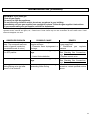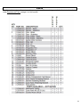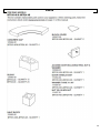
1
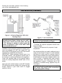
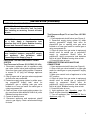
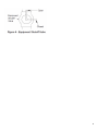
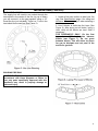
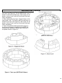
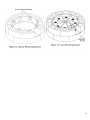
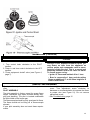
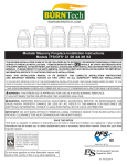
FIRE RING MODELS
BOFP16-48 AND BOFP24-48
NATURAL GAS BURNER
MODELS:
BOFP-48NG
OWNER’S OPERATION AND
INSTALLATION MANUAL
PROPANE/LP GAS BURNER
MODELS:
BOFP-48P
TABLE OF CONTENTS
Safety...................................................................2
Local Codes.........................................................3
Unpacking............................................................3
Specification.........................................................4
Installation............................................................5
Operation............................................................14
Inspecting Burners..............................................15
Wood Burning……………………………………..17
Cleaning and Maintenance.................................18
Troubleshooting..................................................19
Parts....................................................................22
Service Hints.......................................................25
Technical Service................................................25
Replacement Parts..............................................25
Warranty..............................................................26
SAFETY
Solid fuels shall not be burned in this
appliance
This appliance is only for use with the type of
gas indicated on the rating plate. This appliance is not convertible for use with other
gas.
WARNING: This product contains and/or
generates chemicals known to the state of
California to cause cancer or birth defects or
other reproductive harm.
IMPORTANT: Read this owner’s manual carefully and completely before trying to assemble,
operate or service this fireplace. Improper use
of this fireplace can cause serious injury or
death from burns, fire, explosion, electrical
shock and carbon monoxide poisoning.
DANGER: Carbon monoxide poisoning may
lead to death!
Carbon Monoxide Poisoning: Early signs of
carbon monoxide poisoning resemble the flu, with
headaches, dizziness or nausea. If you have these
signs, the fireplace may not be working properly.
Get fresh air at once! Have fireplace serviced.
Some people are more affected by carbon monoxide than others. These include pregnant women,
people with heart or lung disease or anemia, those
under the influence of alcohol and those at high
altitudes.
Natural and Propane/LP gases are odorless. An
odor-making agent is added to these gases. The
odor helps you detect a gas leak. However, the odor
added to the gas can fade. Gas may be present
even though no odor exists.
Make certain you read and understand all warnings.
Keep this manual for reference. It is your guide to
safe and proper operation of this fireplace.
WARNING: Any change to this appliance or its
controls can be dangerous.
Due to high temperatures, the appliance
should be located out of traffic and away from
furniture and draperies.
Do not place clothing or other flammable material on or near the appliance. Never place any
objects on the appliance.
Appliance base assembly becomes very hot
when running appliance. Keep children and
adults away from hot surface to avoid burns or
clothing ignition. Appliance will remain hot for
a time after shutdown. Allow surface to cool
before touching.
Carefully supervise young children when they
are in the vicinity of the appliance.
Keep the appliance area clear and free from
combustible materials, gasoline and other
flammable vapors and liquids.
Do not leave appliance in operation when
unattended.
2
SAFETY (Continued)
1. This appliance is only for use with the type of gas
indicated on the rating plate. This appliance is not
convertible for use with other gases.
2. Do not place propane/LP supply tank(s) inside or
under the fire ring. Locate propane/LP supply
tank(s) at least 10 feet away (propane/LP units
only).
3. If you smell gas
• shut off gas supply
• do not try to light any appliance
• do not touch any electrical switch; do not use
any phone in your building
• immediately call your gas supplier from a neighbor’s phone. Follow the gas supplier’s instructions
• if you cannot reach your gas supplier, call the
fire department
4. To prevent the creation of soot, follow the instructions in Cleaning and Maintenance, page 14.
5. Do not run appliance
• where flammable liquids or vapors are used or
stored
• under dusty conditions
6. Do not use this appliance to cook food or burn
paper or other objects.
7. Do not use this appliance if any part has been
exposed to or under water. Immediately call a
qualified service technician to inspect the room
appliance and to replace any part of the control
system and any gas control which has been under water.
8. Turn appliance off and let cool before
servicing, installing or repairing. Only a qualified
service person should install, service or repair
appliance.
9. This appliances must not be connected to any
external electrical source.
10.Operating appliance above elevations of 4,500
feet may cause pilot outage.
17.To prevent performance problems, do not use
propane/LP fuel tank of less than 100 lb. capacity
(propane/LP units only).
18.Provide adequate clearances around air openings.
LOCAL CODES
UNPACKING
Install and use appliance with care. Follow all local
codes. In the absence of local codes, use the latest
edition of The National Fuel Gas Code, ANSI
Z223.1/NFPA 54*.
*Available from:
American National Standards Institute, Inc.
1430 Broadway
New York, NY 10018
National Fire Protection Association, Inc.
Batterymarch Park
Quincy, MA 02269
1. Remove burner system and other components
from box. Do not grasp by burner tubes. If it is
evident that the burner is damaged, it must be
replaced prior to being put into operation. Set
lava rock boxes aside for further instruction.
2. Remove all protective packaging from pallet of
blocks for shipment.
3. Check for any shipping damage. If appliance is
damaged call Burntech Fireplace Solutions at 1818-564-4225 for replacement parts before
returning to dealer. www.burntech.com
3
SPECIFIATIONS
Figure 1 – BOFP16-48 AND BOFP24-48
BOFP-48NG
• Rating: 96,000 Btu/hr
• Gas Type: Natural Gas Only
• Ignition: Manual
• Manifold Pressure: 6.0" w.c.
• Minimum Inlet Supply Pressure: 7.0" w.c.
• Maximum Inlet Supply Pressure: 10.5" w.c.
• Orifice: #12
BOFP-48P
• Rating: 95,000 Btu/hr
• Gas Type: Propane/LP Gas Only
• Ignition: Manual
• Manifold Pressure: 10.5" w.c.
• Minimum Inlet Supply Pressure: 11" w.c.
• Maximum Inlet Supply Pressure: 14" w.c.
• Orifice: #33
4
INSTALLATION
WARNING: A qualified service person must
install appliance. Follow all local codes.
NOTICE: State or local codes may only allow
operation of this appliance in a vented configuration. Check your state or local codes.
CHECK GAS TYPE
Use the correct type of gas (natural or propane/LP). If
your gas supply is not the correct gas type, do not
install appliance. Call dealer where you bought
appliance for proper type appliance.
WARNING: This appliance is equipped for either
natural gas or propane/LP gas but not both. Gas
type is indicated on the rating plate. Field
conversion is not permitted.
INSTALLATION AND CLEARANCES
WARNING: Maintain the minimum clearances. If
you can, provide greater clearances from floor
and adjoining wall.
MINIMUM CLEARANCE TO COMBUSTIBLE
MATERIALS
Side Wall 16",
Bottom: 0" (For Wood Burning Installation- NonCombustible Floor is Required)
WARNING: DO NOT PLACE UNDER A CEILING
OR OVERHANG.
CONNECTING TO GAS SUPPLY
WARNING: This appliance requires a 1/2"
NPT (National Pipe Thread) inlet connection
to the pressure regulator.
WARNING: A qualified service person must
connect appliance to gas supply. Follow all
local codes.
CAUTION: Never connect propane/LP fire
ring directly to the propane/LP supply. This
appliance requires an external regulator (not
supplied). Install the external regulator between the appliance and propane/LP supply.
WARNING: Never connect natural gas
fire ring to private (non utility) gas wells.
This gas is commonly known as
wellhead gas.
Installation Items Needed
Before installing appliance, make sure you have
the items listed below.
• external regulator (supplied by installer)
• piping (check local codes)
• sealant (resistant to propane/LP gas)
• equipment shutoff valve *
• test gauge connection *
• sediment trap
• tee joint
• pipe wrench
• approved flexible gas line with gas connector
(if allowed by local codes) (not provided)
* An equipment shutoff valve with 1/8" NPT tap is
an acceptable alternative to test gauge
connection. Purchase the optional equipment
shutoff valve from your dealer.
For propane/LP units, the installer must supply
an external regulator. The external regulator will
reduce incoming gas pressure. You must reduce
incoming gas pressure to between 11" and 14" of
water. If you do not reduce incoming gas
pressure, appliance regulator damage could
occur. Install external regulator with the vent
pointing down as shown in Figure 2, page 6.
5
Pointing the vent down protects it from freezing
rain or sleet. www.burntech.com
INSTALLATION (Continued)
CAUTION: Use only new, black iron or steel pipe.
Internally-tinned copper tubing may be used in
certain areas. Check your local codes. Use pipe
of 1/2" diameter or greater to allow proper gas
volume to appliance. If pipe is too small, undue
loss of volume will occur.
Installation must include an equipment shutoff valve,
union and plugged 1/8" NPT tap. Locate NPT tap
within reach for test gauge hook up. NPT tap must be
upstream from appliance (see Figure 3).
IMPORTANT: Install equipment shutoff valve in an
accessible location. The equipment shutoff valve is
for turning on or shutting off the gas to the appliance.
Check your building codes for any special requirements for locating equipment shutoff valve to fireplaces.
Apply pipe joint sealant lightly to male NPT threads.
This will prevent excess sealant from going into pipe.
Excess sealant in pipe could result in clogged
appliance valves.
WARNING: Use pipe joint sealant that is
resistant to liquid petroleum (LP) gas.
* Purchase the optional equipment shutoff valve
from your dealer.
**Minimum inlet pressure for purpose of input
ad-justment.
We recommend that you install a sediment trap in
supply line as shown in Figure 3. Locate sediment
trap where it is within reach for cleaning. Install in
piping system between fuel supply and appliance.
Locate sediment trap where trapped matter is not
likely to freeze. A sediment trap traps moisture
and contaminants. This keeps them from going
into appliance controls. If sediment trap is not
installed or is installed wrong, appliance may not
run properly.
CAUTION: Avoid damage to gas control. Hold
gas control with wrench when connecting it
to gas piping and/or fittings.
6
INSTALLATION (Continued)
CHECKING GAS CONNECTIONS
WARNING: Test all gas piping and connections, internal and external to unit, for leaks
after installing or servicing. Correct all leaks
at once.
WARNING: Never use an open flame to check
for a leak. Apply a noncorrosive leak
detection fluid to all joints. Bubbles forming
show a leak. Correct all leaks at once.
CAUTION: Make sure external regulator has
been installed between propane/LP supply
and appliance. See guidelines under
Connecting to Gas Supply, page 6.
PRESSURE TESTING GAS SUPPLY PIPING
SYSTEM
Test Pressures In Excess Of 1/2 PSIG (3.5 kPa)
1. Disconnect appliance with its appliance main
gas valve (control valve) and equipment shutoff
valve from gas supply piping system. Pressures
in excess of 1/2 psig will damage appliance
regulator.
2. Cap off open end of gas pipe where equipment
shutoff valve was connected.
3. Pressurize supply piping system by either opening propane/LP supply tank valve for
propane/LP gas or opening main gas valve
located on or near gas meter for natural gas or
using compressed air.
4. Check all joints of gas supply piping system. Apply noncorrosive leak detection fluid to all joints.
Bubbles forming show a leak.
5. Correct all leaks at once.
6. Reconnect appliance and equipment shutoff
valve to gas supply. Check reconnected fittings
for leaks.
Test Pressures Equal To or Less Than 1/2 PSIG
(3.5 kPa)
1. Close equipment shutoff valve (see Figure 4).
2. Pressurize supply piping system by either
opening propane/LP supply tank valve for
propane/LP gas or opening main gas valve
located on or near gas meter for natural gas or
using compressed air.
3. Check all joints from gas meter to equipment
shutoff valve for natural gas or propane/LP
supply to equipment shutoff valve for
propane/LP. Apply noncorrosive leak detection
fluid to all joints. Bubbles forming show a leak.
4. Correct all leaks at once.
PRESSURE TESTING APPLIANCE GAS
CONNECTIONS
1. Open equipment shutoff valve (see Figure 4).
2. Open main gas valve located on or near gas
meter for natural gas or open propane/LP supply
tank valve.
3. Make sure control knob of appliance is in the
OFF position.
4. Check all joints from gas meter to equipment
shutoff valve for natural gas or propane/LP
supply to equipment shutoff valve for
propane/LP. Apply noncorrosive leak detection
fluid to all joints. Bubbles forming show a leak.
5. Correct all leaks at once.
6. Light appliance (see Operation, page 15).
Check all other internal joints for leaks.
7. Turn off appliance (see To Turn Off Gas to
Appliance, page 15).
7
8
INSTALLATION (Continued)
GAS LINE PLANNING
The supply line will need to run vertical through the
heat shield in the center of the fire ring up to where
you will connect it to the gas regulator using a 1/2"
flared flex line (not included). There is a 1" hole in the
heat shield for the gas line (See Figure 5).
1. Locate a flat even surface to build your fire
ring. See Specifications page 4 for sizing and
Minimum Clearances page 5 when selecting a
location.
2. Use 8 blocks to build the first layer (See
Figure 6). After laying out all blocks, using a
level, verify all the blocks are level. Shim if
necessary.
FOR PROPANE/LP ONLY: On the first
layer, leave 1/8" head joints between
blocks (see Figure 7). Do not grout
between blocks. This will allow air space
for gas to dissipate and not pool in the
event of a gas leak.
BUILDING FIRE RING
WARNING: Failure to position the parts in
accordance with these diagrams or failure to
use only parts specifically approved with this
appliance may result in property damage or
personal injury.
9
INSTALLATION (Continued)
3. When starting second layer, stagger blocks to the
first layer (see Figure 8). For the BOFP24-48, use 8
blocks to build the second layer. After laying out all
blocks, using a level, verify all the blocks are level.
Shim if necessary.
4 When starting the top layer, stagger blocks to the
layer below. Use 7 full blocks and one half block to
build the top layer (see Figure 9). After laying out all
blocks, using a level, verify all the blocks are level.
Shim if necessary.
5. Place 4 heat shield retaining brackets (longer of
the 2 types of brackets included with the BOFP-48
Series burner system) on the top layer of blocks in
the pattern shown in Figure 10.
Figure 10 - Heat Shield Retaining Brackets
(BOFP16-48 Shown)
Figure 9 - Top Layer (BOFP16-48 Shown)
10
INSTALLATION (Continued)
WARNING: Heat shield must be installed.
7. Place heat shield on the retaining brackets in the
center of the fire ring (see Figure 12).
8. Place 4 burner retaining brackets (shorter of the
2 types of brackets included with the MFRB
Series burner system) on the top layer of blocks
in the pattern shown in Figure 13.
9. Connect incoming gas line to regulator shown
in Figure 5 page 8 before placing burner system
into place.
10. Place burner system on the retainer
brackets in the center of the fire ring with the
controls going through the opening in the blocks
(see Figure 14). DO NOT GRASP BURNER
SYSTEM BY BURNER TUBES.
11. Place lava retaining bracket as shown in
Figure 15.
Figure 14 - Burner System
11
12
INSTALLATION (Continued)
12. Place concrete cap on the top layer of blocks.
Center cap on block. Level and shim if necessary
(See Figure 16).
13. Insert access door into hole as shown in Figure
17.
INSTALLING LAVA ROCK
Lava rock comes with the burner system in two
boxes each weighing around 42 pounds. Lava
rocks range in size. Begin by placing the smaller
rocks between the burner tubes filling the whole
pan in a single layer of rocks. Avoid placing rocks
on the pilot shield. They will obstruct the view of
the pilot when you go to light the pilot. You may
want to light the pilot first before adding the lava
rock (see Lighting Instructions, page 12). Place
larger rocks in a second layer in a smaller circle in
the center of the fire ring. Lastly place the largest
rocks in the center making a teepee formation.
13
OPERATION
FOR YOUR SAFETY READ BEFORE
LIGHTING
WARNING: Keep flue open when operating
unit.
WARNING: If you do not follow these instructions exactly, a fire or explosion may result
causing property damage, personal injury or
loss of life.
A. This appliance has a pilot which must be
lighted by hand. When lighting the pilot,
follow these instructions exactly.
B. BEFORE LIGHTING smell all around the appliance area for gas. Be sure to smell next to
the floor because some gas is heavier than
air and will settle on the floor.
WHAT TO DO IF YOU SMELL GAS
• Do not try to light any appliance.
• Do not touch any electric switch; do not use
any phone in your building.
• Immediately call your gas supplier from a
neighbor’s phone. Follow the gas supplier’s
instructions.
• If you cannot reach your gas supplier, call
the fire department.
C. Use only your hand to push in or turn the
gas control knob. Never use tools. If the knob
will not push in or turn by hand, don’t try to
repair it, call a qualified service technician or
gas supplier. Force or attempted repair may
result in a fire or explosion.
D. Do not use this appliance if any part has
been under water. Immediately call a
qualified service technician to inspect the
appliance and to replace any part of the
control system and any gas control which
has been under water.
smell gas, STOP! Follow “B” in the safety
information, column 1. If you don’t smell gas, go
to the next step.
5. Turn control knob counterclockwise to the
PILOT position and press in. Keep control knob
pressed in for five (5) seconds.
Note: You may be running this fire ring for the
first time after hooking up to gas supply. If so,
the control knob may need to be pressed in for
30 seconds or more. This will allow air to bleed
from the gas system.
• If control knob does not pop up when
released, contact a qualified service person or
gas supplier for repairs.
6. With control knob pressed in, push down and
hold ignitor button until pilot is lit. Visually locate
the pilot on the control valve cover by the edge
of the burner pan to look for flame. If needed,
keep pressing ignitor button until pilot lights.
Note: If the pilot will not stay lit after several tries,
turn the gas control knob to OFF and call your
service technician or gas supplier.
7. Keep control knob pressed in for 30 seconds
after lighting pilot. After 30 seconds, release
control knob.
Note: If pilot goes out, repeat steps 3 through 7.
8. Turn control knob counterclockwise to the ON
position. Burner should light. If burner does not
light, call a qualified service person.
9. To leave pilot lit and shut off burners only, turn
control knob clockwise to the PILOT position.
LIGHTINGINSTRUCTIONS
1. STOP! Read the safety information.
2. Make sure equipment shutoff valve is fully open.
3. Press in and turn control knob clockwise to the
OFF position.
4. Wait five (5) minutes to clear out any gas. Then
smell for gas, including near the floor. If you
14
OPERATION (Continued)
TO TURN OFF GAS TO APPLIANCE
1. Turn control knob clockwise to the PILOT
position.
2. Press in and turn control clockwise to the OFF
position.
3. Close equipment shutoff valve (see Figure 4,
page 7).
CURING
During 2-3 hour appliance break-in period, you
may detect an odor from the appliance as
various paints and compounds used in manufacturing of this fire ring. This is a normal and
temporary situation that is not cause for alarm.
To ensure proper curing:
• Ignite a 2" flame and maintain it for 1 hour.
• Burn in consecutive 1 hour periods raising
flame an additional 2" to full flame height for a
total of three hours.
INSPECTING BURNERS
Check pilot flame pattern and burner flame patterns
often.
PILOT ASSEMBLY
The pilot assembly is factory preset for proper flame
height. Alterations may have occurred during shipping and handling. The pilot is located underneath
the pilot shield on the burner pan.
The thermocouple should be fully enveloped in flame.
The flame should not be lifting off of thermocouple
element.
If your pilot assembly does not meet these requirements:
• Access pilot adjustment screw through slot in valve
cover. Turn adjustment screw clockwise to
decrease or counterclockwise to increase the flame
to proper size (see Figure 21). Do not remove
adjustment screw.
• See Troubleshooting, page 15
15
BURNER FLAME PATTERN
Burner flames will be steady, not lifting or floating.
Flames should go up through middle of the fire ring
burner in a tee pee formation.
Pilot Adjustment Screw
Electronic Ignitor
16
INSTALLATION/OPERATION (Wood Burning)
Wood Burning:
Starting the Fire:
The Burntech Fire Ring is able to burn wood instead
of Natural/Propane Gas. The Installation process is
shown below. (For Wood Burning InstallationNon-Combustible Floor is Required) (note: Wood
Burning installation does not include Half Block
Door, Brackets or burner system.)
Start the first fire slowly with a small amount of
paper and kindling (small dry wood splits or twigs)
stacked in a crossed or teepee fashion toward the
center. Slowly add small but larger pieces of dried
hardwood of about three inches (2”) to four inches
(4”) diameter. The temperature will begin to rise in
your Fire Ring however it may take about 15
minutes to begin a faster temperature ascent.
1. Locate a flat even surface to build your fire
ring. See Specifications page 4 for sizing and
Minimum Clearances page 5 when selecting a
location.
2. Use 8 blocks to build the first layer (See
Figure 6). After laying out all blocks, using a
level, verify all the blocks are level. Shim if
necessary.
3. When starting second layer, stagger blocks to the
first layer (see Figure 8). For the BOFP24-48, use 8
blocks to build the second layer. After laying out all
blocks, using a level, verify all the blocks are level.
Shim if necessary.
4. When starting the top layer, stagger blocks to the
layer below. Use 8 full blocks). After laying out all
blocks, using a level, verify all the blocks are level.
Shim if necessary.
5. Next be sure to line the inside with firebrick to
help radiate the heat out of the Fire Ring.
NOTE: Take care not to feed your fire too fast so as
to smother it. As you add more wood, a temporary
decrease in temperature my occur. This is normal
and as soon as the new wood begins to burn, your
temperature will rise.
The next step is to ensure that your fire continue to
build.
17
CLEANING AND MAINTENANCE
WARNING: Turn off appliance and let cool
before cleaning.
CAUTION: You must keep control areas,
burners and circulating air passageways of
appliance clean. Inspect these areas of
appliance before each use. Have appliance
inspected yearly by a qualified service person.
WARNING: Failure to keep the primary air
opening(s) of the burner(s) clean may result in
sooting and property damage.
BURNER INJECTOR HOLDER AND PILOT
AIR INLET HOLE
The primary air inlet holes allow the proper amount
of air to mix with the gas. This provides a clean
burning flame. Keep these holes clear of dust, dirt,
leaves, lint and pet hair. Clean these air inlet holes
prior to each heating season. Blocked air holes will
create soot. We recommend that you clean the unit
every three months during operation and have
appliance inspected yearly by a qualified service
person.
We also recommend that you keep the burner tube
and pilot assembly clean and free of dust and dirt.
To clean these parts we recommend using
compressed air no greater than 30 PSI. Your local
computer store, hardware store or home center
may carry compressed air in a can. If using
compressed air in a can, please follow the
directions on the can. If you don’t follow directions
on the can, you could damage the pilot assembly.
1. Shut off unit, including pilot. Allow unit to cool for
at least thirty minutes.
2. Inspect burner, pilot and primary air inlet holes
on injector holder for dust and dirt (see Figure
22).
3. Blow air through the ports/slots and holes in the
burner.
4. Check injector holder located at end of burner
tube again. Remove any large particles of dust,
dirt, lint or pet hair with a soft cloth or vacuum
cleaner nozzle.
5. Blow air into the primary air holes on the injector
holder.
6. In case any large clumps of dust have now been
pushed into the burner repeat steps 3 and 4.
Clean pilot assembly also. Additional cleaning may
be needed for proper pilot operation based on
use/lack of use. A yellow tip on the pilot flame may
indicate dust and dirt in the pilot assembly. There is
a small pilot air inlet hole about from where the pilot
flame comes out of pilot assembly (see Figure 23).
With unit off, lightly blow air through air inlet hole.
You may blow through a drinking straw if compressed air is not available.
MAIN BURNER
Periodically inspect all burner flame holes with
appliance running. All slotted burner flame holes
should be open with flame present. All round
burner flame holes should be open with a small
blue flame present. Some burner flame holes may
become blocked by debris or rust, with no flame
present. If so, turn off appliance and let cool.
Remove blockage, blocked burner flame holes will
create soot.
WARNING: The injector holders (air shutters)
are not adjustable. Do not move injector
holders from their original positions.
18
TROUBLESHOOTING
WARNING: Turn off appliance and let cool before servicing. Only a qualified service person should
service and repair appliance.
Note: All troubleshooting items are listed in order of operation.
OBSERVED PROBLEM
When ignitor button is pressed, there is
no spark at pilot
POSSIBLE CAUSE
1. Ignitor electrode not con
nected to ignitor cable
2. Ignitor cable pinched or
wet
3. Broken ignitor cable
4. Bad ignitor
5. Ignitor electrode positioned
wrong
6. Ignitor electrode broken
7. Battery not installed,
battery power low or battery
not installed correctly
When ignitor button is pressed, there is
spark at pilot but no ignition
1. Gas supply turned off or
equipment shutoff valve
closed
2. Control knob not in PILOT
position
3. Control knob not pressed
in while in PILOT position
4. Air in gas lines when
installed
5. Pilot adjustment screw
closed
6. Pilot is clogged
7. Low gas pressure
REMEDY
1. Reconnect ignitor cable
2. Free ignitor cable if
pinched by any metal or
tubing. Keep ignitor cable
dry
3. Replace ignitor cable
4. Replace ignitor
5. Replace pilot assembly
6. Replace pilot assembly
7. Install new alkaline
battery in electronic ignitor.
Verify battery is installed
correctly
1. Turn on gas supply or
open equipment shutoff
valve
2. Turn control knob to
PILOT position
3. Press in control knob
while in PILOT position
4. Continue holding down
control knob. Repeat igniting operation until air is
removed
5. Adjust pilot flame for approximately 2" blue flame
6. Clean pilot (see
Cleaning and Maintenance,
page 14) or replace pilot
assembly
7. Replace gas control
19
TROUBLESHOOTING (Continued)
OBSERVED PROBLEM
Pilot lights but flame goes out when
control knob is released
Burner does not light after pilot is lit
Delayed ignition of burner
Burner flame is too low or too high
POSSIBLE CAUSE
1. Contol knob not fully pressed in
2. Control knob not pressed in long
enough
3. Equipment shutoff valve not fully
open
4. Pilot flame not touching
thermocouple,
which
allows
thermocouple to cool, causing pilot
flame to go out. This problem could
be caused by one or both of the
following:
A) Low gas pressure
B) Dirty or partially clogged pilot
5. Thermocouple connection loose
at control valve
6. Thermocouple damaged
7. Control valve damaged
1. Inlet gas pressure is too low
2. Burner orifice clogged
REMEDY
1. Press in control knob fully
2. After pilot lights, keep control
knob pressed in 30 seconds
3. Fully open equipment shutoff
valve
4. A) Contact local natural or
propane/LP gas company
B) Clean pilot (see Cleaning
and Maintenance, page 14) or
replace pilot assembly
5. Hand tighten until snug, then
tighten 1/4 turn more
6. Replace thermocouple
7. Replace control valve
1. Contact local natural or propane/LP gas company
2. Clean burner (see Cleaning
and Maintenance, page 14)
3.
Thermocouple
leads
dis- 3. Reconnect leads
connected or improperly connected.
4. Burner orifice diameter is too
small
4. Replace burner orifice
1. Pilot flame needs adjusting
1. Adjust pilot flame for approximately 2" blue flame
2. Wrong pilot orifice
2. Replace pilot orifice set
1. Incorrect gas supply or pressure
1. Check for proper gas supply
pressure
2. Blocked burner orifice or burner 2. Free burner orifice and
manifold ports
manifold ports of any burrs,
paint or other blockage
3. Improper burner orifice size
3. Verify proper burner orifice
sizing
20
TROUBLESHOOTING (Continued)
WARNING: If you smell gas
• Shut off gas supply.
• Do not try to light any appliance.
• Do not touch any electrical switch; do not use any phone in your building.
• Immediately call your gas supplier from a neighbor’s phone. Follow the gas supplier’s instructions.
• If you cannot reach your gas supplier, call the fire department.
IMPORTANT: Operating fire ring where impurities in air exist may create odors. Cleaning supplies, paint, paint remover,
cigarette smoke, cements and glues, etc., create fumes. These fumes may mix with combustion air and create odors. These
odors will disappear over time.
OBSERVED PROBLEM
Burner is excessively noisy
(Note: The movement and combustion of gas will create low,
unavoidable levels of noise.)
Gas odor even when control knob
is in OFF position
Gas odor during combustion
Fire ring produces a
clicking/ticking noise just after
burner is lit or shuts off
POSSIBLE CAUSE
1. Passage of air/gas across
irregular surfaces
2. Excessive flame impingement or
blockage
1. Gas leak. See Warning at top of
page
REMEDY
1. Relieve any tight bends or kinks
in gas supply line
2. Check/reset gas regulator
pressure
1. Locate and correct all leaks
(See Checking Gas Connections,
page 7)
2. Control Valve defective
2. Replace control valve
1. Gas leak. See Warning at top of 1. Locate and correct all leaks
page
(See Checking Gas Connections,
page 7)
1. Metal expanding while heating or 1. This is normal. If noise is
contracting while cooling
excessive, contact qualified service
person
21
PARTS
BURNER MODELS BOFP-48NG, BOFP-48P
22
PARTS
This list contains replaceable parts used in your appliance. When ordering parts, follow the instructions listed
under Replacement Parts on page 21 of this manual.
23
PARTS
24
REPLACEMENT PARTS
SERVICE HINTS
Note: Use only original replacement parts. This
will protect your warranty coverage for parts
replaced under warranty.
Contact authorized dealers of this product. If they
can’t supply original replacement part(s), call
Burntech Fireplace Solutions at (818) 564-4253.
When calling, have ready:
• your name
• your address
• model and serial numbers of your appliance
• how appliance was malfunctioning
• purchase date
Usually, we will ask you to return the part to the
factory.
When Gas Pressure Is Too Low
• pilot will not stay lit
• burners will have delayed ignition
• appliance will not produce specified heat
• propane/LP gas supply may be low
You may feel your gas pressure is too low. If so,
contact your local propane/LP or natural gas
supplier.
TECHNICAL SERVICE
You may have further questions about installation,
operation or troubleshooting. If so, contact
Burntech Fireplace Solutions at (818) 564-4253.
When calling please have your model and serial
numbers of your appliance ready.
You can also visit our web site at
www.burntech.com.
25
Limited Warranty
Fire Ring
Burntech Fireplace Solutions warrants all Burntech manufactured products to be free from defects in materials
that adversely affect Fire Ring performance for a period of ten (10) years from the date of purchase, subject to the
terms and conditions of this limited warranty. Burner, Valves and electronic parts are only covered for one year,
parts and labor per the valve manufacturer’s warranty. The manufacturer’s warranty for the electronic ignition and
valve is for one year.
This warranty covers only products manufactured by Burntech Fireplace Solutions, and NO WARRANTY, EXPRESS
OR IMPLIED, EXTENDS TO ANY OF THE HARDWARE, FOUNDATION, VENTING, DUCTS, OR ACCESSORIES. THIS
WARRANTY DOES NOT COVER DRAFTING, SMOKING, OR SOOTING OF THE Burntech Fire Ring. Factors beyond the
manufacture’s control may affect drafting, smoking, and sooting, Burntech Fireplace Solutions cannot guarantee
these aspects of performance.
If a component is found to be defective under the terms of this warranty, the party this warranty is extended to
shall notify Burntech Fireplace Solutions, 6520 Platt Ave #577 West Hills, CA 91307 in writing, by registered mail,
within thirty (30) days following the discovery of the defect within the warranty period. The letter shall contain (1)
the date of the purchase; (2) place of purchase; (3) address of installation; (4) name, address and phone number of
the homeowner; and (5) a brief description of the defect.
Burntech Fireplace Solutions, or any entity thereof, is not responsible for any labor costs or indirect costs incurred
for the replacement of defective components.
Burntech Fireplace Solutions is not responsible for misuse or mishandling of the component parts. Nothing in this
warranty makes Burntech Fireplace Solutions, or any entity thereof, liable in any respect for any injury or damage
to the building or structure in which the Toscana Oven has been installed or to the persons or property therein
arising out of the use, misuse, or installation of property manufactured Burntech Fireplace Solutions product.
Burntech Fireplace Solutions, OR ANY ENTITY THEREOF, SHALL NOT BE HELD LIABLE FOR ANY INCENDENTAL OR
CONSEQUENTIAL DAMAGES OR EXPENSES ARISING OUT OF THE USE OF THE Burntech Fire RIng. ALL DAMAGES
AND EXPENSES ARE HEREBY EXCLUDED.
This warranty is null and void when the Fire Rings are not installed pursuant to the installation instructions
provided by Burntech Fireplace Solutions and local building codes have not been followed completely.
This warranty applies only to those Fire Rings installed in the continental United States, Hawaii, Alaska and Canada.
If any part of this warranty is found to be unenforceable, the remaining parts shall remain in force and effect.
Burntech Fireplace Solutions HEREBY DISACLAIMS ALL GUARANTEES AND WARRANTIES, EXPRESS OR IMPLIED,
BEYOND THE WARRANTIES SET FORTH HEREIN.
CUSTOMER SERVICE & PARTS REPLACEMENT:
Parts and accessories may be purchased from your local dealer. Additional information is available from Burntech
Fireplace Solutions Accessory orders will be accepted by mail, or you may call to order Monday thru Friday from
1:00 p.m. to 5:00 p.m. (Pacific Standard Time) at: (818) 564-4253
Please complete the following information for future reference and warranty verification:
Date of Purchase ____________________20_____
Serial # ____________________
26