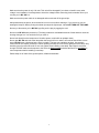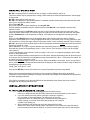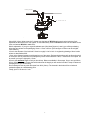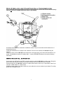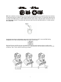
1
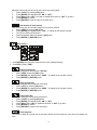
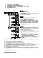
MY 250 USER MANUAL
(V1.12)
Elektralite is a division of Group One. 70, Sea Lane, Farmingdale, NY 11735, USA.
Tel: +1 (516)-249-3662. Fax: +1 (516)-249-8870
WWW.MYELEKTRALITE.COM
Introduction
Thank you for choosing Elektralite’s MY 250 fixture.
Please read the User Manual carefully and keep it in a safe place after reading it.
MY 250 is very easy to install and use once you have read the manual. Failure to do so could result in damage
to the fixture, which will not be covered under warranty so please take the time to read it.
When you unpack MY 250 you should find inside the box: the fixture, a 120 volt power cable, a 3 pin DMX
signal cable, a safety cable and of course this CD. Please check carefully that there is no damage caused by
transportation. Should there be any, consult your dealer immediately and don’t install it.
Features
Pan 630° / Tilt 265° with 16-bit resolution.
Speed control channel for Pan and Tilt.
Electronic focus.
8 colors plus white and rainbow effect
6 rotating gobos plus open white.
7 fixed gobos plus open.
Gobo shake and gobo indexing.
3 facet rotating prism with 16 in-built macro effects.
Strobe : with a frequency of 0~15 flashes per second with random function.
Dimmer 0 to 100%.
Automatic programs : 8 pre-built programs can be selected.
Display : digital address and function setting (also the display can be inverted if
fixture is hung upside down).
Local or remote resetting
Lamp switch ON/OFF locally
Auto test for all functions
Value of each DMX-channel can be displayed
Saved Program : You can edit and save a program internally in the fixture by using either the
display panel of the fixture or using an external controller (your Elektralite CP10xt or CP20xt). You
can save a maximum of 48 scenes. You can then run this saved program by using the “run” feature
from the menu on the display panel
SAFETY INSTRUCTIONS
A Word of Caution.
Please remember you will be working with 120 volts and you can suffer electric shock from any exposed lives
wires. So please be careful at all times and behave wisely.
Now you’re MY 250 left Elektralite’s factory in perfect condition. In order to maintain this condition and to
ensure a safe operation, it is absolutely essential that the installer and user follow the safety instructions and
warning notes written in this user manual. Remember any damage caused by disregarding the manual or not
reading it, will not be covered by warranty and Elektralite (or any of its dealers) will not accept responsibility for
any resulting damage or problems.
If MY 250 has been exposed to large environmental temperature changes in transit please do not switch it on
immediately it is unpacked. There maybe internal condensation. So leave MY 250 off until it has reached the
running temperature of the venue.
Elektralite’s MY 250 needs to be grounded. Do NOT cut the ground pin or try to use two-core cable to connect
it to a 120-volt receptacle. To be safe and to work properly you must have this fixture grounded.
A qualified electrician must do any electrical work.
1
Make sure that the power is only 120 volts. This unit will be damaged if you chose to install it at any other
voltage. In an installation it is always best to check the voltage before connecting. And remember never try to
connect you’re MY 250 live.
Make sure that the power cable is not damaged and never break off the ground pin.
Always disconnect the power, when the device is not in use or before cleaning it. If you don’t then you are
wasting the lamp life. Merely closing the shutter just stops the light output, it does NOT TURN OFF THE LAMP.
Never try to disconnect you’re MY 250 by pulling out the plug by tugging the cord.
Never touch MY 250 when powered up. The lamp produces a considerable amount of heat and as a result the
housing does get hot. You can be burnt if you touch it.
Never look directly into the lamp source. Sensitive person could suffer an epileptic shock.
Never open MY 250 and look at the lamp when the lamp is still on or when it is turned off but still hot or even
warm. MY 250 uses a discharge lamp, which is volatile. The lamp can explode at anytime. Use extreme
caution and do not expose yourself to it. When replacing the lamp do not touch any glass part of the lamp. Only
handle by the silver terminal ends. Do not over tighten when installing a new lamp. Hand tight is more than
enough. PLEASE make sure that power to the fixture is disconnected and allow the fixture to cool down to
room temperature before installing a new lamp.
Please keep out of reach of the general public, children and animals.
2
GENERAL GUIDELINES
MY 250 is a lighting effect for professional use on stages, in clubs, theatres, and so on.
This fixture should only be operated at the voltage, which stated in the technical specifications in the last page
of this manual.
MY 250 is designed for indoor use only.
MY 250 is not designed for permanent operation. Consistent operation breaks may ensure that the device will
serve you for a long time without defects.
Do not shake MY 250.
Do not use physical force when installing or operating MY 250.
While choosing the installation position, please make sure that MY 250 is not exposed to extreme heat,
moisture or dust.
The minimum distance from MY 250 output front lens to any illuminated surface must be more than 3 feet.
Please be careful what surface you shine the light onto; light also has heat and this can affect the illuminated
surface. Elektralite will not be responsible for fading, color distortion or heat distortion caused by the light
beam.
When you hang MY 250 please use an appropriate safety cable. Please make sure that any hanging
equipment, like threaded rod or C clamp is appropriate for the job. Remember, with a moving yoke fixture, that
the momentum of moving this large mass will cause extra “stress” on any mounting materials. When mounting
MY 250 in the air be sure to use bolts which are M10.The M10 bolts should be no less than 25mm long and the
thread type should be 1.5mm.
Metric explanation:- If you go to a good hardware store (like Home Depot or Lowe’s) you will be purchasing
bolts that have written on the packaging 10mm x 1.5mm x 25mm. [The last figure of 25mm can be a higher
value read on].
10mm is the diameter of the bolt itself. 10mm is roughly 0.4 of an inch. In engineering drawings 10mm is also
written or described as M10.
1.5mm is the distance between each thread or turn of the screw. Engineering drawings refer to this as the pitch
of the screw. Now in places like Home Depot they stock 10mm bolts with 1.0mm, 1.25mm and 1.5mm pitch. So
be careful you buy the right pitch: 1.5mm.
25mm is the minimum length of bolt you should use. Bolts are available in 5mm steps. So you can get 25mm,
30mm, 35mm and so on. Choose the bolt that best fits the length you will need to hold the C clamp or whatever
clamping device you will be using.
Finally, just FYI 25.4mm is 1 inch.
Only operate MY 250 you know its functions. Do not permit operation by persons not qualified.
Please use the original packaging if the device is to be transported. [Beware the majority of shipping
companies will not accept any liability for damage if the fixture is not shipped in the manufacturer’s original box
and insert packaging material].
If this fixture is operated in any other way different to that described in this manual, the fixture could be
damaged and any warranty would be void.
INSTALLATION INSTRUCTIONS
A). Installing or replacing the lamp
1. Install the lamp with the fixture unplugged from the electric source.
Never try to replace a lamp with the fixture still turned on and still hooked up to the electric.
2. If you are replacing the lamp, before opening the housing to replace it,
let it cool down to room temperature. The lamp burns at very high
temperatures and it is a discharge lamp. If the lamp has been running then
expect anything up to half an hour before the housing is cool enough to
consider even opening up.
3. When installing a new lamp do not touch any glass part of the lamp.
Always use a clean cloth to handle lamps. The sweat from your fingers will cause the lamp to
burn incorrectly and will shorten lamp life. If you do touch the glass, then check in the lamp box
3
for a special wipe to clean the lamp.
4. Only install Philips MSD 250 or MSD 250/2 GY9.5 lamp. Any other lamp is not acceptable.
Procedure:
1. Unscrew the 3 screws on the top of the housing. The lamp is underneath the plate. Carefully remove
the metal plate.
2. Then unscrew the 2 big screws and gently pull the socket holder using the knob in the middle.
3. Carefully insert the lamp into the socket making sure the spring clips secure the lamp socket
correctly. Then insert the plate back into the fixture and fasten the 2 screws back in place.
4. On the plate there are 3 small screws marked 1, 2 and 3. These are used to adjust the lamp. You can
adjust the 3 screws to fine-tune the position of the lamp. In this way you can achieve the maximum
output from the lamp.
Please remember the lamp is not a hot-restrike type. You must wait for approximately 10
Minutes, after having turned off the lamp, before you can turn it back on again.
Warning- Never ever operate the lamp when it is not inside the fixture. MSD lamps are volatile and could
possible explode. Only turn on the fixture with the lamp securely inside the fixture and the cover plate screwed
on.
B). Mounting MY 250.
Method 1: Installation using a C clamp.
The installation must always be secured with a backup safety attachment: namely an appropriate sized safety
cable. Don’t clamp the safety to a C clamp. That defeats the reason for a safety cable….namely a SEPARATE
backup to the primary hanging mechanism.
Never stand directly below the device when mounting, removing or servicing the MY 250.
Please make sure MY 250 has been installed correctly both from a mechanical and electrical aspect before
powering up and operating for the first time. Spending a few extra minutes double-checking everything is better
than rushing to turn the fixture on.
Care should be taken to mount MY 250. Make sure that MY 250 is mounted in such a way that no one can
touch it directly. For example, when hanging MY 250 make sure it is high enough up not to hit anyone’s head or
run into any obstruction in its movement. Always keep MY 250 away from any inflammable material.
Mounting MY 250 is a job that requires qualified personnel with experience. If the personnel doing the
installation lack these qualifications do not use them to do the installation.
4
Safety-chain
M 10 X 25m m
.
Using M10 (10mm) bolts screw the C clamps onto the base of MY 250 make sure that the bolts are firmly
tightened but take care not to over tighten. Fit a suitable safety chain to MY 250’s center hole and attach to the
truss or whatever MY 250 is attached to.
Metric explanation:- If you go to a good hardware store (like Home Depot or Lowe’s) you will be purchasing
bolts that have written on the packaging 10mm x 1.5mm x 25mm. [The last figure of 25mm can be a higher
value read on].
10mm is the diameter of the bolt itself. 10mm is roughly 0.4 of an inch. In engineering drawings 10mm is also
written or described as M10.
1.5mm is the distance between each thread or turn of the screw. Engineering drawings refer to this as the pitch
of the screw. Now in places like Home Depot they stock 10mm bolts with 1.0mm, 1.25mm and 1.5mm pitch. So
be careful you buy the right pitch: 1.5mm.
25mm is the minimum length of bolt you should use. Bolts are available in 5mm steps. So you can get 25mm,
30mm, 35mm and so on. Choose the bolt that best fits the length you will need to hold the C clamp or whatever
clamping device you will be using.
Do not attempt to use any other bolt apart from M10 (10mm). The threads in the holes will be ruined and
rendered useless as a load bearing point.
Finally, just FYI 25.4mm is 1 inch.
5
Method 2 : Installation using U Bracket Claps with half Cheeseboros/couplers.
[The U brackets and the appropriate base for the mounting these brackets are an after sales accessory.
They do not come as standard when the fixture is purchased].
U brackets can be used as an alternative installation method. They can have either half cheeseboros or C
clamps fitted to them.
Fit the half cheeseboros or C clamps to the U brackets. Then fit the U brackets to the MY 250 using the
camlocs.
Finally, fit a safety chain to MY 250 and remember don’t clamp the safety to the same half cheeseboros or C
clamp. That defeats the reason for a safety cable….namely a SEPARATE backup to the primary hanging
mechanism.
DMX-512 control connection.
Connect the 3 pin XLR cable to the DMX controller and then to the first MY 250 in the daisy chain. Doing this
way round avoids the pain of rewiring, if you get the wrong end of the cable back at the controller.
Continue wiring from one MY 250 to another in a daisy chain manner. Never try to Y split cables. Never try to
“star wire” a DMX cable run, it will not work.
If additional cable needs to be made up then two-core cable with a screen needs to be purchased. For wiring
please see the diagram below.
6
DMX has a maximum running distance of 330 feet. When long distances are involved then there is a tendency
for electrical noise to be evident. In which case a DMX terminator will be required. The terminator helps prevent
corruption of the DMX signal. To make a DMX terminator simply solder a 120 ohm resistor across pins 2 and 3
of an XLR male connector. Then place that connector at the very end of the DMX cable run. In other words at
the last MY 250.
It maybe the case that you will need to connect a 5 pin XLR to the 3 pin XLR. In a normal DMX wiring
configuration, the 5 pin is soldered identically to the 3 pin. So in the 5 pin
1: Ground
2: Signal (-)
3: Signal (+)
Pins 4 and 5 are not used. Be very sure you read the pin numbering on the connector when you solder up the
connector. Do not just wire up the three pins to the left or right because the male and female connector has the pins
on different “sides” of the connector! Read the pin numbers.
7
Projector DMX start address selection
In order for the controller like Elektralite’s CP10xt to control each MY 250 it has to know where it is in the daisy
chain of DMX. To do this all MY150s have to be set to a start address. To understand the concept of a starter
address we also have to understand the concept of channels and the features those channels have.
MY 250 uses 14 channels of DMX. Those channels control the features of MY 250. They are as follows:CHANNEL 1 : select one of the 9 colors, color cycle or rainbow effect
CHANNEL 2 : select one of the 6 gobo’s + open or gobo cycle+ gobo shake
CHANNEL 3 : select gobo rotation speed and direction
CHANNEL 4 : select one of the 7 gobos + open or gobo cycle + gobo shake.
CHANNEL 5 : pan movement (max. 630°)
CHANNEL 6 : tilt movement (max. 265°)
CHANNEL 7 : speed pan/tilt movement, blackout selection
CHANNEL 8 : select prism or normal lens + prism rotation and speed. Also 16 prism macros.
CHANNEL 9 : focus
CHANNEL10: select strobe (0 – 15 flashes per second). Both linear & random strobe.
CHANNEL11: dimmer 0-100%. (N.B. this channel only works when channel 10 is between dmx level 32-63).
CHANNEL12: auto program control + lamp on, motor reset and lamp switch off.
CHANNEL13: pan fine.
CHANNEL14: tilt fine.
So if we start with the first MY 250 its first channel is 1. So we refer to it as having a starter address of 1.
The second MY 250 will then have its first channel or starter address at channel 17.
The third MY 250 will then have its first channel or starter address at channel 33, the fourth MY 250 will start on
049 and so on. Now if you want two MY 250s to be always the same in color, movement and so on then you
can set both of them to the same address. In this way you can create groups of fixtures having the same effects
happen at the same time. There is no restriction on how many MY 250s you have on the same starter address
If you just bought four MY 250 and it came with an Elektralite CP10xt, the starter addresses in the
CP10xt have already been set. All you have to do is set the starter addresses on the four MY250s.
If you have another controller, then you will have to set it’s starter addresses for each MY 250 before you will be
able to control any MY 250
Tips & Tricks
1. If you change the address on MY 250 it may appear not to have accepted that address. Turn MY 250
off wait until the lamp cools down (remember it is not a hot re-strike lamp) and then turn it back on
again.
2. When you turn on MY 250, if it is receiving data, the display will show “A.001” or “A.017” or whatever
the address is for MY 250. If there is still no data getting to MY 250, then run a cable directly from the
controller to the fixture.
8
The display panel.
The display panel on MY 250 offers many features. For example, you can set the starting address, switch on
and off the lamp, run the pre-programmed program or make a reset.
The Main Menu is accessed by pressing the ENTER button until the display starts flashing which will be about
3 seconds. You can scroll through the menu using the UP button. Then use the ENTER button again to select
the menu you want. Confirm every selection by pressing the ENTER button. You can change the selection by
using the UP button and you can exit a sub-menu by pressing the EXIT button.
The features of the display panel are listed as follows:-
Default settings shaded.
Main
menu
Sub menu
Extension
Display
Function
ADDR
VALU
SLAV
A001~A511 (AXXX)
ON/OFF
(SLAV)
DMX address setting
Slave setting
EBOC
OFF
ALON
(AU-A)
MAST
(AU-M)
ALON
(SO-A)
MAST
(SO-M)
AUTO
0
MODE
RUN
SOUN
VALU
DISP
1
LAMP
2
SET
3
ADJU
4
TIME
5
EDIT
D–00 ~ D-30
(DXXX)
ON/OFF
ON/OFF
No functions
Automatic Program Run
in Stand Alone
Automatic Program Run
as Master
Sound-controlled Program
Run in Stand Alone
Sound-controlled Program
Run as Master
Display the DMX 512 value
of each channel
Reverse display
Shut off LED display
Lamp on/off
OPEN
RDIS
CLDI
ON/OFF
ONLI
ON/OFF
Lamp on/off via controller
DELA
D–00 ~ D-59,D-15
Delay lamp on
RPAN
ON/OFF
Pan Reverse
RTIL
ON/OFF
Tilt Reverse
16BI
REST
LODA
VER
LADJ
TEST
MATI
ON/OFF
ON/OFF
ON/OFF
V-1.0~V-9.9
ON/OFF
T–01 ~ T–30
0000~9999 (hours)
Switch 16 bit/8 bit
Reset
Restore factory settings
Software version
Lamp adjustment
Test function of each channel
Fixture running time
LATI
0000~9999 (hours)
Lamp running time
CLMT
ON/OFF
Clear fixture time
CLLT
ON/OFF
Clear lamp time
STEP
S–01 ~ S–48
SC01
~
SC48
C–01 ~ C–30
Steps of Program Run
Edit the channels of each
scene
Time for each scene
Edit program via controller
TIME (sec.)
CNIN
01XX (00~FFH)
30XX (00~FFH)
T – – X (1~9)
ON/OFF
9
Main functions
- Main menu 0
1. Press [ENTER] for 3 seconds to enter the main menu "MODE" (display flashing)
2. Press [ENTER] and select "ADDR", “RUN” or "DISP" by pressing [UP] button.
3. Press [ENTER] for selecting the desired sub menu.
- DMX address setting, Slave setting
- DMX address setting
This function, adjusts the desired DMX-address via the Control Board.
1. Select “VALU“ by pressing [UP] button.
2. Press [ENTER], adjust the DMX address by pressing [UP] or [DN].
3. Press [ENTER] to confirm.
4. Press [EXIT/DN] to return to main menu.
- Slave setting
This function, turns MY 250 into a slave.
1. Select “SLAV” by pressing [UP] button.
2. Press [ENTER], the display shows “ON” or “OFF”.
3. Press [UP] to select “ON” to enable this function or “OFF” if you don’t.
4. Press [ENTER] to confirm.
5. Press [EXIT/DN] to return to the main menu.
- No functions
- Program Run, Master setting
This function "RUN", runs the internal program. You can set the number of steps under Step. You can edit
the individual scenes under Edit. You can run the individual scenes either automatically (AUTO), i.e. with the
adjusted Step-Time or sound activated (SOUN). The selection "ALON" means Stand Alone-mode and
"MAST" means MY 250 is the master.
10
1.
2.
3.
4.
5.
Select "AUTO" or "SOUN" by pressing [UP].
Press [ENTER] for selecting the desired extension menu.
Select "ALON" or "MAST" by pressing [UP].
Press [ENTER] to confirm.
Press [EXIT/DN] to return to the main menu.
- Display the DMX-value, Reverse display, Shut off LED display
- Display the DMX 512 value of each channel
This function displays the DMX 512 value of each channel.
1. Select "VALU" by pressing [UP].
2. Press [ENTER] to confirm; the display shows“D-00”. In this setting, the DMX value will be adjusted
for every channel will be displayed.
3. Press [UP] in order to select the desired channel. If you select “D-14” the display will only show the
DMX-value of the 14th channel.
4. Press [ENTER] to confirm.
5. The display shows "D- XX“, ”X” stands for the DMX-value of the selected channel.
6. Press [ENTER] or [EXIT/DN] to exit.
- Reverse display
This function rotates the display by 180°.
1. Select "rDIS" by pressing [UP].
2. Press [ENTER], the display shows “ON” or “OFF”.
3. Press [UP] to select “ON” if you wish to enable this function or “OFF” if you don’t; the display will
rotate by 180°.
4. Press [ENTER] or [EXIT/DN] to exit.
- Shut off LED display
This function shuts off the LED display after 2 minutes.
1. Select "CLDI" by pressing [UP].
2. Press [ENTER], the display shows “ON” or “OFF”.
3. Press [UP] to select “ON” if you wish to enable this function or “OFF” if you don’t.
4. Press [ENTER] or [EXIT/DN] to exit.
- Main menu 1
11
1. Press [ENTER] for 3 seconds to enter the main menu (display flashing).
2. Press [UP] to select “LAMP”.
- Lamp on/off
This function switches the lamp on or off via the display panel.
1.
Select "OPEN" by pressing [UP] button.
2.
Press [ENTER], the display shows “ON” or “OFF”.
3.
Press [UP] to select “ON” if you wish to switch on the lamp or “OFF” if you wish to switch it off.
4.
Press [ENTER] to confirm.
5.
Press [EXIT/DN] to return to the main menu.
- Lamp on/off via external controller
This function switches the lamp on or off via an external controller like the Elektralite CP10xt.
1.
Select “ONLI” by pressing [UP] button.
2.
Press [ENTER], the display shows “ON” or “OFF”.
3.
Press [UP] to select “ON” if you wish to enable this function or “OFF” if you don’t.
4.
Press [ENTER] to confirm.
5.
Press [EXIT/DN] to return to the main menu.
- Delay lamp on
This function delays the lamp ignition.
1.
Select "DELA" by pressing [UP] button.
2.
Press [ENTER] to confirm; the display shows “D-00”. In “D-00”, the lamp strikes immediately.
3.
Press [UP] to select the desired delay between "00" and "59" minutes.
4.
If you select “D-03” the lamp will strike after 3 minutes.
5.
Press [ENTER] to confirm.
6.
Press [EXIT/DN] to return to the main menu.
- Main menu 2
1. Press [ENTER] for 3 seconds to enter the main menu (display flashing).
2. Press [UP] to select “SET”.
- Pan Reverse
This function reverses the Pan movement.
1.
Select “rPAN” by pressing [UP] button.
2.
Press [ENTER], the display shows “ON” or “OFF”.
3.
Press [UP] to select “ON” to enable this function or “OFF” if you don’t.
4.
Press [ENTER] or [EXIT/DN] to exit.
12
- Tilt Reverse
This function reverses the Tilt movement.
1.
Select “rTIL” by pressing [UP] button.
2.
Press [ENTER], the display shows “ON” or “OFF”.
3.
Press [UP] to select “ON” to enable this function or “OFF” if you don’t.
5.
Press [ENTER] or [EXIT/DN] to exit.
- Switch 16 bit/8 bit
This function switches MY 250 from 16 bit to 8 bit resolution.
1.
Select “16BI” by pressing [UP] button.
2.
Press [ENTER], the display shows “ON” or “OFF”.
3.
Press [UP] to select “ON” to set 16 bit, or “OFF” to set 8 bit. The channels PAN Fine
and TILT Fine will be disabled.
4.
Press [ENTER] or [EXIT/DN] to exit.
- Reset
This function resets MY 250 via the display panel.
1.
Select “rEST” by pressing [UP] button.
2.
Press [ENTER], the display shows “ON” or “OFF”.
3.
Press [UP] to select “ON” to enable this function or “OFF” if you don’t.
4.
Press [ENTER] or [EXIT/DN] to exit.
- Restore factory settings
This function restores the factory settings of the device. All settings will be reset to the default values
(shaded). Any edited scenes will be lost.
1.
Select “LODA” by pressing [UP] button.
2.
Press [ENTER], the display shows “ON” or “OFF”.
3.
Press [UP] to select “ON” to enable this function or “OFF” if you don’t.
4.
Press [ENTER] to confirm.
5.
Press [EXIT/DN] to return to the main menu.
- Software version
This function displays the software version of the device.
1.
Select “VER” by pressing [UP] button.
2.
Press [ENTER], the display shows “V-X.X”, “X.X“ stands for the version number, e.g. “V-1.0”,
“V-2.6”.
3.
Press [ENTER] or [EXIT/DN] to return to the main menu.
- Main menu 3
1. Press [ENTER] for 3 seconds to enter the main menu (display flashing).
2. Press [UP] to select “ADJU”.
- Lamp adjustment
With this function you can adjust the lamp via the Control Board. The shutter opens and the lamp can be
13
adjusted. In this mode, the device will not react to any control signal.
1.
Select “LADJ” by pressing [UP] button.
2.
Press [ENTER], the display shows “ON” or “OFF”.
3.
Press [UP] to select “ON” if you wish to enable this function or “OFF” if you don’t.
4.
Press [ENTER] to confirm.
5.
Press [EXIT/DN] in order to return to the main menu.
- Test function of each channel
With this function you can test each channel on its (correct) function.
1.
Select “tESt” by pressing [UP] button.
2.
Press [ENTER], the display shows “T-XX”, “X” stands for the channel number.
3.
The current channel will be tested.
4.
Select the desired channel by pressing [UP] button.
5.
Press [ENTER] or [EXIT/DN] to exit.
- Main menu 4
1. Press [ENTER] for 3 seconds to enter the main menu (display flashing).
2. Press [UP] to select “TIME”.
- Fixture running time
This function displays the running time of MY 250.
1.
Select “MATI” by pressing [UP] button.
2.
Press [ENTER], the display shows “XXXX”, “X“ stands for the number of hours.
3.
Press [ENTER] or [EXIT/DN] to exit.
- Lamp running time
This function displays the running time of the lamp.
1.
Select “LATI” by pressing [UP] button.
2.
Press [ENTER], the display shows “XXXX”, “X“ stands for the number of hours.
3.
Press [ENTER] or [EXIT/DN] to exit.
- Clear fixture time
This function clears the running time of the device.
1.
Select “CLMT” by pressing [UP] button.
2.
Press [ENTER], the display shows “ON” or “OFF”.
3.
Press [UP] to select “ON” to enable this function or “OFF” if you don’t.
4.
Press [ENTER] to confirm.
5.
Press [EXIT/DN] to return to the main menu.
- Clear lamp time
This function clears the running time of the lamp. Please clear the lamp time every time you replace the
lamp.
14
1.
2.
3.
4.
5.
Select “CLLT” by pressing [UP] button.
Press [ENTER], the display shows “ON” or “OFF”.
Press [UP] to select “ON” to enable this function or “OFF” if you don’t.
Press [ENTER] to confirm.
Press [EXIT/DN] to return to the main menu.
- Main menu 5
1. Press [ENTER] for 3 seconds to enter the main menu
(display flashing).
2. Press [UP] to select “EDIT”.
- Define the number of steps in Run
This function defines the number of steps in the Program
Run.
1. Select “STEP” by pressing [UP] button.
2. Press [ENTER], the display shows “S-XX”, “X” stands
for the total amount of steps you want to save, so you
can call up to 48 scenes in “RUN”. For example if the “XX”
is 05, it means that “RUN” will run the first 5 scenes you
saved in “EDIT”.
3. Press [ENTER] to save and exit.
- Editing the channels of the individual scenes
This function can edit the program to be called up in Run.
a) Editing via the Control Board
1. Select “SC01” by pressing [UP] button.
2. Press [ENTER], the display shows “SCXX”, “X” stands
for the scene no. to be edited.
3. Change the scene no. by pressing [UP].
4. Press [ENTER], the display shows “C-X”, “X” stands
for the channel no. Such as “C-01”, it means you are
editing channel 1 of the selected scene.
5. Select the channel number you would like to edit by
pressing [UP].
6. Press [ENTER] to enter editing for the selected channel,
the fixture reacts to your settings. The display shows the DMX value of the edited channel. Such as “ 11XX”, it
stands for in the channel 11 of the editing scene, the DMX value is XX , XX is a hexadecimal number value
“01-FF”.
7. Adjust the desired DMX value by pressing [UP] or [DN].
8. Press [ENTER] in order to edit other channels of this scene.
9. Repeat steps 5-9 until you finish setting all the DMX values for all channels of this scene.
10. Once all the channels completed, the display will flash “tIME”
11. Press [ENTER] to edit the time needed, the display shows “t--X”,“X” stands for the time needed to run the
current scene, value “1-9”. For example, “t--2” means you need 2 seconds to run the current scene.
12. Adjust the desired time by pressing [UP].
13. Press [ENTER] to save the settings for the scene you are editing, the display will change to the next scene
automatically.
14. Repeat step 3-14 to edit and other scenes, you can edit and save a maximum of 48 scenes.
15. Press [EXIT/DN] to exit. The number of steps can be defined under “STEP” and the scenes can be called
up under “RUN”
b) Editing via the external controller
15
Call up the first scene in your controller now.
1. Select “SC01” by pressing [UP] button.
2. Press [ENTER], the display shows “SC01”.
3. Press [ENTER], the display shows “C-01”.
4. Select "CNIN" by pressing [UP].
5. Press [ENTER], the display shows "OFF".
6. Press [UP], the display shows "ON".
7. Press [ENTER], the display shows "SC02". You successfully downloaded the first scene.
8. Adjust the Step-time as described above under point 12.
9. Call up the second scene in your controller now.
10. Repeat steps 5-11 until all desired scenes are downloaded.
11. Press [EXIT/DN] to exit. The number of steps can be defined under “STEP” and the scenes can be called
up under “RUN”
16
INSTRUCTIONS ON USE:
The moving head is controlled by 14 DMX channels
CHANNEL 1 : select one of the 9 colors, color cycle or rainbow effect
CHANNEL 2 : select one of the 6 gobo’s + open or gobo cycle+ gobo shake
CHANNEL 3 : select gobo rotation speed and direction
CHANNEL 4 : select one of the 7 gobos + open or gobo cycle + gobo shake.
CHANNEL 5 : pan movement (max. 630°)
CHANNEL 6 : tilt movement (max. 265°)
CHANNEL 7 : speed pan/tilt movement, blackout selection
CHANNEL 8 : select prism or normal lens + prism rotation and speed. Also 16 prism macros.
CHANNEL 9 : focus
CHANNEL10: select strobe (0 – 15 flashes per second). Both linear & random strobe.
CHANNEL11: dimmer 0-100%. (N.B. this channel only works when channel 10 is between dmx level 32-63).
CHANNEL12: auto program control + lamp on, motor reset and lamp switch off.
CHANNEL13: pan fine.
CHANNEL14: tilt fine.
17
DMX channel’s function and values:
Channel 1 – Color Wheel:
0-13
Open / white
14-27
Orange
28-41
Blue
42-55
Green
56-69
Yellow
70-83
Red
84-97
Magenta
98-111
Light Blue
112-128
Yellow & Green
128-187
188-193
Forwards rainbow effect from fast to slow
No rotation
194-255
Backwards rainbow effect from slow to fast
Channel 2 – Rotating gobos:
0-9
Open
10-19
Rot. gobo 1
20-29
Rot. gobo 2
30-39
Rot. gobo 3
40-49
Rot. gobo 4
50-59
Rot. gobo 5
60-69
Rot. gobo 6
70-89
Gobo 1 shake slow to fast
90-109
Gobo 2 shake slow to fast
110-129
Gobo 3 shake slow to fast
130-149
Gobo 4 shake slow to fast
150-169
Gobo 5 shake slow to fast
170-189
190-255
Gobo 6 shake slow to fast
Rot. gobo wheel cont. rotation slow to fast
18
Channel 3 – Rotation gobo index , rotating gobo
0-127
Gobo indexing
128-187
188-191
Forward gobo rotation from fast to slow
No rotation
192-255
Backwards gobo rotation from slow to fast
Channel 4 –Fixed Gobos
0-13
Open/hole
14-27
Gobo 1
28-41
Gobo 2
42-55
Gobo 3
56-69
Gobo 4
70-83
Gobo 5
84-97
Gobo 6
98-111
Gobo 7
112-127
Gobo 1 shake slow to fast
128-143
Gobo 2 shake slow to fast
144-159
Gobo 3 shake slow to fast
160-175
Gobo 4 shake slow to fast
176-191
Gobo 5 shake slow to fast
192-207
Gobo 6 shake slow to fast
208-223
Gobo 7 shake slow to fast
224-255
Gobo wheel rotation from slow to fast
Channel 5 – PAN coarse movement (8 bit)
Channel 6 – TILT coarse movement (8 bit)
Channel 7 –Speed pan/tilt movement
0-14
max speed
15-225
max to min speed
226-235
blackout by movement
236-245
blackout by all wheel changing
246-255
No rotation
19
Channel 8 –3 facet rotating prism, Prism / Gobo macros
0-3
open
4-63
64-67
Forwards rotation from fast to slow
No rotation
68-127
Backwards rotation from slow to fast
128-135
Macro 1
136-143
Macro 2
144-151
Macro 3
152-159
Macro 4
160-167
Macro 5
168-175
Macro 6
176-183
Macro 7
184-191
Macro 8
192-199
Macro 9
200-207
Macro 10
208-215
Macro 11
216-223
Macro 12
224-231
Macro 13
232-239
Macro 14
240-247
Macro 15
248-255
Macro 16
Channel 9 – Focus
0-255
Continuous adjustment from far to near
Channel 10 –Shutter, strobe
0-31
Shutter closed
32-63
Dimmer control (shutter open)
64-95
Strobe effect slow to fast
96-127
No function (shutter open)
128-159
Pulse-effect in sequences
160-191
No function (shutter open)
192-223
Random strobe effect slow to fast
224-255
No function (shutter open)
Channel 11 – Dimmer (intensity)
0-255
Intensity 0 to 100%
20
Channel 12 – Lamp on/off, reset, internal
0-19
color change normal by direction depend on distance
20-39
color change to any position by direction depend on distance
40-59
Lamp on
60-79
Lamp switch off
80-99
Motor reset
100-119
Internal program 1
120-139
Internal program 2
140-159
Internal program 3
160-179
Internal program 4
180-199
Internal program 5
200-219
Internal program 6
220-239
Internal program 7
240-255
Internal program 8
Channel 13 – Pan fine
Channel 14 – Tilt fine
ERROR MESSAGE
When you turn on the fixture, it will reset first. The display may show “Xer” while there are problems with one or
more channels. “XX” stands for channel 1,2,3,5,6,7 which has the testing sensor for positioning .
So, for example, when the display shows “02Er”, it means there is some error in channel 2. If there are errors
on channel 1, channel 2, channel 5 at the same time, you will see the error message “01Er”, “02Er”,”05Er” flash
repeated for 5 times. Then the fixture will generate a reset signal to all the stepper motors. If the error message
remains after performing reset more than 3 times, it will detect whether the fixture has more than 3 errors.
01Er:
Color wheel error. This message will appear after resetting MY 250 and the magnetic-indexing circuit
malfunctions (sensor failed or magnet missing) or the stepper motor is defective (or it could be the drive circuit
on the main circuit board). Normally after a reset, the color wheel will go to its default position.
02Er:
Rotating gobo wheel error. This message will appear after resetting MY 250 and the magnetic-indexing circuit
malfunctions (sensor failed or magnet missing) or the stepper motor is defective (or it could be the drive circuit
on the main circuit board). Normally after a reset, the rotating gobo wheel will go to its default position.
03Er:
Rotating gobo indexing error. This message will appear after resetting MY 250 and the magnetic-indexing
circuit malfunctions (sensor failed or magnet missing) or the stepper motor is defective (or it could be the drive
circuit on the main circuit board). Normally after a reset, the rotating gobo will go to its default position.
04Er:
Fixed gobo wheel error. This message will appear after resetting MY 250 and the magnetic-indexing circuit
malfunctions (sensor failed or magnet missing) or the stepper motor is defective (or it could be the drive circuit
on the main circuit board). Normally after a reset, the fixed gobo wheel will go to its default position
05Er:
Pan movement error. This message will appear after resetting MY 250 and the yoke’s magnetic-indexing circuit
malfunctions (sensor failed or magnet missing) or the stepper motor is defective (or it could be the drive IC on
the main circuit board). Normally after a reset, the yoke will go to its default position.
21
06Er:
Tilt head movement error. This message will appear after resetting MY 250 and the head’s magnetic-indexing
circuit malfunctions (sensor failed or magnet missing) or the stepper motor is defective (or it could be the drive
IC on the main circuit board). Normally after a reset, the head will go to its default position.
08Er:
Prism wheel error. This message will appear after resetting MY 250 and the magnetic indexing circuit
malfunctions (sensor failed or magnet missing) or the stepper motor is defective (or it could be the drive circuit
on the main circuit card). Normally after a reset, the head will go to its default position.
CLEANING AND MAINTENANCE
1. All bolts and safety chains must be tightly screwed into position and have no corrosion.
2. Regularly check all mechanic moving parts for wear. They must rotate freely and in no way stick or
squeak.
3. Regularly look for wear and tear on the 120 volt input cable and the DMX signal cable.
4.
Clean MY 250 at frequent intervals. Use a moist lint free cloth. Do not use a wet cloth or a cloth with
alcohol or solvents added. Clean lens and the reflector when the lamp is off, disconnected from the
120 supply and when it is cool.
TECHNICAL SPECIFICATIONS
Power supply : 120VAC, 60Hz
Power consumption : max. 400 VA
Lamp : MSD250/2 GY9.5 socket, Metal Halide
Motors : 11 micro motors
Packing dimensions :66cm x 56cm x52 cm [26” x 22” x 21”]
Net weight : 25 KGS; 55 lbs
Gross weight: 29 KGS; 64 lbs.
[Errors and omissions for all information given in this manual is excepted.
All information is subject to change without prior notice].
Registering your MY250
It is very important that you register your MY 250 so that you can receive any updates and have your warranty
in operation. To register please fill in the warranty form which can be found at www.myelektralite.com
[Manual Updates. V1.12 = V1.1 + explanation of M10 bolts & insert on 3 to 5 pin DMX XLRs].
22
Other Elektralite Products include :
[Also check out our website at www.myelektralite.com]
CP-3 Controller.
CP-10xt Controller.
CP-16 /24 Controller.
23
CP-20xt Controller.
TurboFog + Fog Machine.
24