1
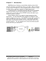
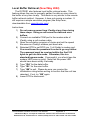
Remote Data Collection Device CE Model DCDSS1 Documentation Number DCDSS11702 This product designed and manufactured in Ottawa, Illinois USA of domestic and imported parts by International Headquarters B&B Electronics Mfg. Co. Inc. 707 Dayton Road -- P.O. Box 1040 -- Ottawa, IL 61350 USA Phone (815) 433-5100 -- General Fax (815) 433-5105 Home Page: www.bb-elec.com Orders e-mail: [email protected] -- Fax (815) 433-5109 Technical Support e-mail: [email protected] -- Fax (815) 433-5104 European Headquarters B&B Electronics Ltd. Westlink Commercial Park, Oranmore, Co. Galway, Ireland Phone +353 91-792444 -- Fax +353 91-792445 Home Page: www.bb-europe.com Orders e-mail: [email protected] Technical Support e-mail: [email protected] 2002 B&B Electronics July 2001 -- Revised May 2002 Documentation Number DCDSS11702 Manual Cover Page B&B Electronics Mfg Co – 707 Dayton Rd - PO Box 1040 - Ottawa IL 61350 - Ph 815-433-5100 - Fax 815-433-5104 B&B Electronics Ltd – Westlink Comm. Pk – Oranmore, Galway, Ireland – Ph +353 91-792444 – Fax +353 91-792445 B&B Electronics RESERVED. No part of this publication may be reproduced or transmitted in any form or by any means, electronic or mechanical, including photography, recording, or any information storage and retrieval system without written consent. Information in this manual is subject to change without notice, and does not represent a commitment on the part of B&B Electronics. B&B Electronics shall not be liable for incidental or consequential damages resulting from the furnishing, performance, or use of this manual. All brand names used in this manual are the registered trademarks of their respective owners. The use of trademarks or other designations in this publication is for reference purposes only and does not constitute an endorsement by the trademark holder. Table of Contents Chapter 1: Introduction .................................................... 1 Chapter 2: Operation ......................................................... 2 Data Storage......................................................................... 2 Data Buffer and Time Stamping .............................. 2 Polling Strings.......................................................... 2 Data Delivery Triggers .......................................................... 2 Time-Based Trigger ................................................. 2 Buffer-Based Trigger ............................................... 3 Digital Input Trigger ................................................. 3 Data Delivery Methods ......................................................... 3 Error Conditions.................................................................... 3 Serial Ports ........................................................................... 4 ISP Account .......................................................................... 4 Email Setup .......................................................................... 5 FTP Setup............................................................................. 5 Pager Setup.......................................................................... 5 Time Setup ........................................................................... 6 Bypass Mode ........................................................................ 6 Remote Buffer Retrieval (New! May 2002) ........................... 6 Local Buffer Retrieval (New! May 2002)……………………... 8 Chapter 3: Setup ................................................................ 8 Firmware Updates ................................................................ 8 Chapter 4: Specifications.................................................. 9 Appendix A: Declaration of Conformity .......................A-1 Documentation Number DCDSS11702 Manual Table of Contents B&B Electronics Mfg Co – 707 Dayton Rd - PO Box 1040 - Ottawa IL 61350 - Ph 815-433-5100 - Fax 815-433-5104 B&B Electronics Ltd – Westlink Comm. Pk – Oranmore, Galway, Ireland – Ph +353 91-792444 – Fax +353 91-792445 i Chapter 1: Introduction B&B Electronics iCaddy is a serial data collection device that uses the Internet to automatically deliver your data. Data is emailed or sent using FTP based on a user-programmable schedule or when its buffer level is reached or based on a digital alarm input. It replaces local or long distance phone calls with an automated Internet connection to your Internet Service Provider. Instead of calling out to remote sites, let the DCDSS1 deliver the data to you, virtually anywhere, anytime! Once installed, there is no need for human presence at the remote site. You can download cash receipts at midnight or track distant conditions at any time. The DCDSS1 works with a modem to call a local ISP near your remote location. User-friendly software with easy-to-read screens allows you to set automatic call-ins from multiple locations. You can change call-in times and data requests at any time from your central PC. Documentation Number DCDSS11702 Manual Appendix A 1 B&B Electronics Mfg Co – 707 Dayton Rd - PO Box 1040 - Ottawa IL 61350 - Ph 815-433-5100 - Fax 815-433-5104 B&B Electronics Ltd – Westlink Comm. Pk – Oranmore, Galway, Ireland – Ph +353 91-792444 – Fax +353 91-792445 Chapter 2: Operation Data Storage Data Buffer and Time Stamping The DCDSS1 has a 60 Kbyte data buffer for storing data collected through the local serial port and time stamp information. The time stamp can be enabled to record the time that the data came into the local serial port. A new time stamp is created when new data is received after one minute of inactivity. Polling Strings Many serial devices require data to be requested before responding. The DCDSS1 can be programmed with up to 10 polling strings, each string up to 35 bytes in length. Each polling string is individually configured and sent out of the local serial port on a timebased trigger. In the PC setup software, fields are chosen to schedule the polling interval of each polling string for minutes, hours and days. Instead of a fixed interval, you can also select which day of the month the polling string should be sent to the local device. Data Delivery Triggers The DCDSS1 will automatically connect through your ISP to deliver its data and notifications. Three different types of events can trigger the data delivery. Time-Based Trigger The time-based trigger can be user-configured to deliver data based on time and date. For example, data may be delivered once every hour, at 9:00 p.m. each Sunday, or on the first day of each month. In the PC setup software, fields are chosen to schedule the delivery interval for minutes, hours and days. Instead of a fixed interval, you can also select which day of the month that data should be delivered. 2 Appendix A Documentation Number DCDSS11702 Manual B&B Electronics Mfg Co – 707 Dayton Rd - PO Box 1040 - Ottawa IL 61350 - Ph 815-433-5100 - Fax 815-433-5104 B&B Electronics Ltd – Westlink Comm. Pk – Oranmore, Galway, Ireland – Ph +353 91-792444 – Fax +353 91-792445 Buffer-Based Trigger The buffer-based trigger automatically dials the modem after the data buffer is a determined percentage full. The range is from 10% to 80% in 5% increments. Keeping the buffer trigger below 100% capacity allows for additional data to be stored while the connection is being made. Digital Input Trigger The digital input trigger dials the modem when an input signal is detected on the DCDSS1 digital input. It is a +5 volt signal, which can be set to active high or active low. The signal must stay active for at least 5 milliseconds to be detected. Data Delivery Methods Data and error logs can be emailed using a MIME attachment or sent using FTP. Additionally, notifications can be configured to allow email or pager notification that data has been delivered. Error Conditions The DCDSS1 has a 2.9 Kbyte error log buffer for storing error conditions. Each error condition is time stamped. Error Condition Logged BYTE(S) LOST DATA OVERRUN DATA ERROR NOTIFICATION FAILED DATA ATTACHMENT FAILED ERROR ATTACHMENT FAILED FTP FAILED Cause Data received from the local serial port during ISP communications or when in Bypass Mode is not stored Onboard UART FIFO overflowed Character received with parity, framing or break error An error occurred in the email notification process (mail server connection, command structure, etc.) An error occurred in the email data process (mail server connection, command structure, etc.) An error occurred in the email error log process (mail server connection, command structure, etc.) An error occurred in the FTP process (FTP server connection, Documentation Number DCDSS11702 Manual Appendix A 3 B&B Electronics Mfg Co – 707 Dayton Rd - PO Box 1040 - Ottawa IL 61350 - Ph 815-433-5100 - Fax 815-433-5104 B&B Electronics Ltd – Westlink Comm. Pk – Oranmore, Galway, Ireland – Ph +353 91-792444 – Fax +353 91-792445 PAGER FAILED DATA OVERFLOW ERROR OVERFLOW PRIMARY DIALUP FAILED PRIMARY AUTHENTICATION FAILED SECONDARY DIALUP FAILED SECONDARY AUTHENTICATION FAILED command structure, etc.) Unable to contact pager or send message Data buffer filled, most recent data stored Error buffer filled, most recent errors stored Unable to connect to ISP1 Unable to verify username/password with ISP1 Unable to connect to ISP2 Unable to verify username/password with ISP2 Serial Ports The DCDSS1 has two serial ports. One connects to the modem; the other is for collecting the serial data. The modem side serial port is always set up for 8 data bits, one stop bit, and no parity bit. The baud rate for the modem side serial port can be set from 600 to 115.2 kbps. A 60-byte initialization string can be programmed to be sent to the modem before the ISP number is dialed. This port is configured as a DTE device; a standard serial modem cable should be used to connect it to a modem. The local serial port can be configured for 5 – 8 data bits, 1 or 2 stop bits, and even, odd or no parity. The baud rates for the local serial port can be set from 300 baud to 115.2k baud. This port is set up as DTE and supports TD and RD data lines. ISP Account The DCDSS1 allows for a primary and secondary (backup) ISP account. If the DCDSS1 is unable to connect to the primary ISP, three attempts will be made before switching to the secondary ISP for that delivery. Subsequent deliveries will revert back to the primary ISP. Note: The DCDSS1 supports Password Authentication Protocol (PAP) for logging into the ISP. Challenge Handshake Authentication Protocol (CHAP) is not supported by the DCDSS1. The user must supply a user name and password for each ISP account. The user name and password are limited to 30 bytes each. Note that AOL, Netzero, Juno, MSN, Earthlink, and others use non-standard protocols and cannot be used with the DCDSS1. 4 Appendix A Documentation Number DCDSS11702 Manual B&B Electronics Mfg Co – 707 Dayton Rd - PO Box 1040 - Ottawa IL 61350 - Ph 815-433-5100 - Fax 815-433-5104 B&B Electronics Ltd – Westlink Comm. Pk – Oranmore, Galway, Ireland – Ph +353 91-792444 – Fax +353 91-792445 Email Setup The DCDSS1 allows for a primary and secondary mail server. The primary mail server is used when the primary ISP is dialed. The secondary mail server is used when the secondary ISP is dialed. For the primary and secondary mail servers, the IP address, port number and MIME filename need to be supplied by the user. The DCDSS1 stores up to ten email addresses for notification and delivering the collected data. The email addresses can be up to 50 bytes each. A user email address for the reply field is also limited to 50 bytes. The subject for the DCDSS1’s email will be <the event> <the trigger> <user defined ID>. The user defined ID can be up to 32 characters long. Some sample subject lines are listed below. <data><buffer> SWfieldPump#1 <error><time>StorageTank4 <notification><digital>WestEntrance FTP Setup The DCDSS1 allows for a primary and secondary FTP server. The primary FTP server is always tried first. If the primary FTP server fails, the secondary FTP server is used. Both the primary and secondary FTP servers require the FTP server’s IP address, port number, FTP username, FTP password, file name, and pathname for the data file. The username and password can be up to 30 bytes each; the pathname can be up to 50 bytes. The filename can be up to 10 bytes long, and can be set to increment each time a file is downloaded by adding a two-digit number to the beginning of the filename. Pager Setup The DCDSS1 allows for one numeric pager to be dialed. The numbers dialed and message sent, including pauses and spaces, can be up to 50 characters long. The pager can be dialed any time one of the modem triggers has been tripped to notify that an event has occurred. Documentation Number DCDSS11702 Manual Appendix A 5 B&B Electronics Mfg Co – 707 Dayton Rd - PO Box 1040 - Ottawa IL 61350 - Ph 815-433-5100 - Fax 815-433-5104 B&B Electronics Ltd – Westlink Comm. Pk – Oranmore, Galway, Ireland – Ph +353 91-792444 – Fax +353 91-792445 Time Setup The DCDSS1 setup software uses the local clock from the computer to set the time during configuration. You can adjust the time and date using the supplied configuration software. The DCDSS1 keeps track of the hour, minute, day, month, year, and day of the week. It can also be set up to automatically adjust for daylight savings time. Bypass Mode The DCDSS1 features a Bypass Mode that allows you to make direct modem connections to the remote device. When the DCDSS1 detects an incoming call from the modem from your software, it automatically switches to bypass mode, allowing you to communicate directly to the remote serial device. Remote Buffer Retrieval (New! May 2002) The DCDSS1 now features a remote buffer retrieval mode. This feature allows the user to manually the gather data or error stored in the buffer at any time remotely. This mode uses modem-to-modem communication, so a modem and a simple emulation program (like SimpTerm, downloadable from www.bb-elec.com) are necessary. Instructions: 1) Connect the local modem to an available COM port. 2) Open the emulation program of choice. 3) Raise/set DTR and RTS. 4) Dial the number that iCaddy’s modem is on (like “ATDT 18454335100<carriage return>”) and wait for confirmation of connection. If successful, go on to 5. If not, lower DTR and go back to 3. 5) You must know the password in order to go any further. The password must be received within the first 100 bytes to get into this mode. Otherwise, this is a standard bypass mode. Next, type “!RT” (read time command). You should have received 3 bytes if successful. If not, re-enter password. 6) Type “!DA” for the data buffer. 7) Type “!EL” for the error buffer. 8) Type “!##” to exit. Please be sure you receive the initialization string before exiting to confirm the unit has rebooted. If not, try “!##” again. 9) Lower DTR and RTS to disconnect. 6 Appendix A Documentation Number DCDSS11702 Manual B&B Electronics Mfg Co – 707 Dayton Rd - PO Box 1040 - Ottawa IL 61350 - Ph 815-433-5100 - Fax 815-433-5104 B&B Electronics Ltd – Westlink Comm. Pk – Oranmore, Galway, Ireland – Ph +353 91-792444 – Fax +353 91-792445 Local Buffer Retrieval (New! May 2002) The DCDSS1 also features local buffer retrieval mode. This feature allows the user to manually gather the data or error stored in the buffer at any time locally. This mode is very similar to the remote buffer retrieval method. However, it does not require a modem. It still requires a simple emulation program (like SimpTerm, downloadable from www.bb-elec.com). Instructions: 1) Do not remove power from iCaddy at any time during these steps. Doing so will erase the data and error buffers. 2) Connect an available COM port to the modem side of iCaddy using a null modem cable. 3) Open the emulation program of choice and set the speed the same as iCaddy’s modem port baud rate. 4) Raise/set DTR to set DCD (pin 1) of iCaddy’s modem port. You must know the password in order to go any further. The password must be received within the first 100 bytes to get into this mode. Otherwise, this is a standard bypass mode. If successful, you should see the modem LED come on solid. Note that the power LED should have been solidly lit already. 5) Type “!DA” for the data buffer. 6) Type “!EL” for the error buffer. 7) Type “!##” to exit. Please be sure you receive the initialization string before exiting to confirm that the unit has rebooted. If not, try “!##” again. 8) Lower DTR to disconnect. Documentation Number DCDSS11702 Manual Appendix A 7 B&B Electronics Mfg Co – 707 Dayton Rd - PO Box 1040 - Ottawa IL 61350 - Ph 815-433-5100 - Fax 815-433-5104 B&B Electronics Ltd – Westlink Comm. Pk – Oranmore, Galway, Ireland – Ph +353 91-792444 – Fax +353 91-792445 Chapter 3: Setup The DCDSS1 comes with setup software to run on your PC. The latest version of the setup software can be downloaded from B&B Electronics web site at www.bb-elec.com. This setup software will allow Windows users (Win 95, 98, ME, 2000, XP, or NT 4.0) to quickly set up the DCDSS1 operational variables, or copy existing variables over to a new device. These variables can be set up through the local serial port, or from a dial-in modem so you can configure and modify the DCDSS1 whether it’s on your desk or at a remote site. The initial DCDSS1 setup must be done through the local serial port. To program the variables through the local serial port, the SETUP jumper found inside the enclosure must be set to CONFIG before the power is plugged in. This will set the DCDSS1 to configure mode. Use the provided null modem setup cable to connect the local serial port of the DCDSS1 to any available serial port of your computer and then run the iCaddy setup software. Follow the setup instructions in the software. When configuration is complete, unplug the power and move the SETUP jumper to the RUN position. Remove the configuration cable. Note that this cable is a Null Modem connection and can only be used during configuration. If a replacement setup cable is needed, it can be purchased from B&B Electronics as part number 232NM9. To program the DCDSS1 remotely through a dialup modem, a password has to be set. This is done for security and to prevent raw binary data from editing the variables inadvertently. The password is up to 10 bytes long. The iCaddy setup software allows you to select a modem from the computer, put the DCDSS1 into setup mode, send the variables, and restart the DCDSS1 in run mode. Firmware Updates The DCDSS1 is flash programmable, allowing its internal software to be updated. The firmware updates can be programmed only through the local serial port. Any update will be available on B&B Electronics web site, www.bb-elec.com. 8 Appendix A Documentation Number DCDSS11702 Manual B&B Electronics Mfg Co – 707 Dayton Rd - PO Box 1040 - Ottawa IL 61350 - Ph 815-433-5100 - Fax 815-433-5104 B&B Electronics Ltd – Westlink Comm. Pk – Oranmore, Galway, Ireland – Ph +353 91-792444 – Fax +353 91-792445 Chapter 4: Specifications Serial Ports Modem Port: Data Rates: ISP: Local Port: Data Rates: Data Bits: Stop Bit: Parity: Serial Data Buffer Size: RS-232, DTE, DB9 male connector 600 – 115,200 baud, N-8-1 only User configurable for primary and secondary (fallback) ISP accounts Supports standard (AT command set) modems RS-232, DTE, DB9 male connector 300 – 115.2 kbps 5, 6, 7, or 8 1, 1.5, or 2 None, even, or odd 60 Kbytes Triggers for Data Delivery Time Based Trigger: Configurable from once per minute to once per month Buffer Trigger: Configurable 10 – 80% of buffer capacity Digital Input: Active high or low, 0 – 5V input, 5 ms min. pulse width Removable terminal block connection Data/Fault Notification: E-mail or pager Data Delivery: FTP or e-mail attachment (MIME) Timestamp: User enabled, new data time-stamped after 1 minute of idle Number of Polling Strings: 10 user definable, each with independent transmit schedule Max. Polling Strings Length: 35 bytes per string Email Addresses Supported: 10 Pager Supported: 1 FTP Addresses Supported: 2 Mounting: Desktop or panel mount using provided holes in case flange Power Requirements: 10–30 VDC, 650 mW maximum Removable terminal block connection Indicators: 3 LED’s for power/status, modem, and local serial port activity Size: 6.5 x 4.9 x 1.5 in (16.5 x 11.2 x 3.5 cm) Shipping Weight: 0.9 lb (0.4 kg) Software (included): CD for Windows 95/98/ME/2000/XP/NT 4.0 Documentation Number DCDSS11702 Manual Appendix A 9 B&B Electronics Mfg Co – 707 Dayton Rd - PO Box 1040 - Ottawa IL 61350 - Ph 815-433-5100 - Fax 815-433-5104 B&B Electronics Ltd – Westlink Comm. Pk – Oranmore, Galway, Ireland – Ph +353 91-792444 – Fax +353 91-792445 Appendix A: Declaration of Conformity DECLARATION OF CONFORMITY Manufacturer’s Name: Manufacturer’s Address: Model Numbers: Description: Type: Application of Council Directive: Standards: B&B Electronics Manufacturing Company P.O. Box 1040 707 Dayton Road Ottawa, IL 61350 USA DCDSS1 Remote Data Collection Device Light industrial ITE equipment 89/336/EEC EN 50082-1:1998 EN 61000 (-4-2, -4-3, -4-4, -4-6) William H. Franklin III, Director of Engineering Documentation Number DCDSS11702 Manual Appendix A A-1 B&B Electronics Mfg Co – 707 Dayton Rd - PO Box 1040 - Ottawa IL 61350 - Ph 815-433-5100 - Fax 815-433-5104 B&B Electronics Ltd – Westlink Comm. Pk – Oranmore, Galway, Ireland – Ph +353 91-792444 – Fax +353 91-792445