1
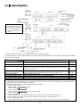
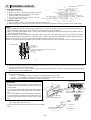
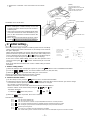
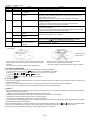
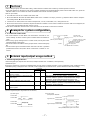
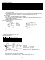
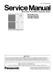
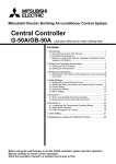
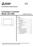
Mitsubishi Electric Air-conditioner Network System
Central Controller
Model: G-50A
Installation Manual
Contents
ON/OFF
CENTRAL CONTROLLER
G-50A
1.
2.
3.
4.
5.
6.
7.
8.
9.
Safety precautions to be observed without fail ........ 1
Confirmation of parts .............................................. 2
Outline dimensions ................................................. 2
System diagram ...................................................... 3
Installation method .................................................. 4
1. Part prepared at site ........................................ 4
2. Installation method .......................................... 4
Initial setting ............................................................ 5
1. Address setting method ................................... 5
2. Function selection method .............................. 5
3. IP address setting method ............................... 6
4. Group setting ................................................... 6
5. Others .............................................................. 6
Test run ................................................................... 7
Example for system configuration ........................... 7
1. To control a K control model ............................ 7
External input/output usage method ....................... 7
1. External signal input function .......................... 7
2. External signal output function ........................ 8
3. LAN connection function ................................. 9
4. RS232C connection function ........................... 9
Before using the controller, please read this Installation Manual carefully to ensure
correct operation. Store this Installation Manual in a location that is easy to find.
This manual describes the installation of the central controller and wiring to the air conditioner. Refer to the installation manual of the
air conditioner. Carefully read item 1 Safety precautions to be observed without fail before installing the unit.
1
Safety precautions to be observed without fail
* Hazards and levels of danger that can occur due to incorrect handling are classified by the following symbols.
Warning
Incorrect handling can result in death, serious injury, etc.
Cautions
Incorrect handling can result in injury or damage to the building or its contents.
* After reading this manual, keep in a handy place. When removing or repairing the unit, give this manual to the installer. When the user
changes, also give to the new user.
Warning
Ask your dealer or technical representative to install.
If incorrect installation is done by a customer, it may cause
an electric shock, fire, etc.
Securely install in a place which can withstand the
weight of the controller.
If it is not enough, the unit may fall and cause an injury.
Securely connect the wiring using the specified cables
and fix them so that the stress from the cables is not
applied to the terminal connection sections.
If connection or fixing is not sure, it may cause heat generation, a fire, etc.
Never modify or repair by yourself.
If the controller is modified or a repair is not correct, it may
cause an electric shock, fire, etc.
Consult your dealer if repairs are necessary.
Securely install the controller according to the installation manual.
If installation is not correct, it may cause an electric shock,
fire, etc.
The electric work should be perform by authorized personal according to the installation manual.
Any lack of electric circuit or any deficiency caused by installation may result in an electric shock or fire.
Do not move and re-install the unit by yourself.
If installation is not correct, it may cause an electric shock,
fire, etc.
Ask your dealer or technical representative.
Cautions
Do not install the controller in a place where flammable
gas could leak.
If gas leaks and collects around the unit, it may cause a fire
or explosion.
Do not install this controller in a place where steam is
generated such as bathroom, kitchen, etc.
Avoid placing where water condenses on the walls. It may
cause an electric shock or malfunction.
Do not use this controller in an abnormal environment.
If the controller is used in a place where there is much oil
(including machine oil), steam or sulfide gas, the performance of the controller may deteriorate or parts may be damaged.
Do not install this controller in a place where an acid or
alkaline solution, special spray, etc. is used frequently.
It may cause an electric shock or malfunction.
Perform wiring so the tension is not applied.
If tension is applied, it may cause disconnection, heat generation or a fire.
Seal the wire lead-in port with putty to prevent the entry
of dew, water, insects, etc.
It may cause an electric or malfunction.
Do not wash this controller with water.
It may cause an electric shock or malfunction.
Do not install this controller in a place where the ambient temperature exceeds 40°C (104°F) or drops below
0°C (32°F), also do not install in a place where it is exposed to direct sunlight.
It may cause a deformation or malfunction.
Use specified wires corresponding to the current capacity for wiring.
Otherwise it may cause power leakage, heat generation or
fire.
Do not touch the PCB (Printed Circuit Board) with your
hand or a tool. Also do not get dirt on the PCB.
It may cause a fire or malfunction.
Do not touch the switches with wet hands.
It may cause an electric shock or malfunction.
Do not press the switches with sharp objects.
It may cause an electric shock or malfunction.
Do not connect an AC power source to the M-NET and
Power (DC12V) terminal blocks of this device.
It may cause a breakdown or fire.
–1–
2
Confirmation of parts
* Please confirm that in addition to this Installation Manual the following items are enclosed in the box.
No.
1
2
3
4
5
6
7
Part name
Qty.
1
1
2
2
1
3
1
Central controller
Installation plate
Wood screw 4.1✕16 (use when directly installing on the wall)
M4 round head screw for main unit installation
M3 round head screw for cover fixing
M4 countersunk screw (M4✕40) for installation plate fixing
Instruction book
* If the screw enclosed for installation plate fixing cannot be used because the wall is thick, prepare an M4 countersunk screw with a
length matching the wall thickness.
* Besides the above parts, purchase a power supply unit (PAC-SC50KUA) that supplies power (DC12V) to the central controller and to
the M-NET transmission line.
3
Outline dimensions
Unit: mm (in)
300 (11-13/16)
70 (2-3/4)
120 (4-3/4)
ON/OFF
CENTRAL CONTROLLER
G-50A
3 (1/8)
46 (1-13/16)
104 (4-15/16)
116 (4-9/16)
19 (3/4)
57 (2-1/4)
34 (1-5/16)
Installation plate
280 (11)
288 (11-11/32)
138 (5-7/16)
–2–
83 .5 (3-9/32)
S
12VDC GND
RS232C
1 CN1 5
POWER
47 (1-27/32)
106 (4-3/16)
13 (1/2)
83.5 (3-9/32)
B
1
CN2
9
28 (1-1/8)
A
M-NET
91 (3-19/32)
Ethernet
21 (13/16)
47 (1-27/32)
4
System diagram
K control
outdoor unit
Group 13
Group 11
K transmission converter
211
Model:PAC-SC25KAA
NOTE
• This diagram does not show
the AC power supply wiring.
Only the configuration for
the transmission line is
shown.
M-NET
outdoor unit
K
K
Group No.
BC controller
Group 3
Central controller
Model: G-50A
The numbers in the
indicate the address No.
LOSSNAY
ME
Group 1
M-NET
Local remote controller
M-NET side: PAR-F27MEA(ME)
PAC-SE51CRA(CR)
MA side:
PAR-20MAA(MA)
PAR-FA(FL)31MA
M-NET transmission line
K transmission line
MA remote controller line
M-NET
outdoor unit
LAN
Group No.
Indoor unit
MA
Group 2
MA
Power supply unit (optional)
Model:PAC-SC50KUA
Power(DC12V)
* Address setting for each M-NET device (The same address cannot be duplicated.)
* The K transmission converter (PAC-SC25KAA) and OA processing unit (LOSSNAY) are not included in systems shipped to North
America (USA & Canada).
Indoor unit
Outdoor unit
BC controller/OS controller
K control side remote controller
M-NET remote controller
MA remote controller
OA processing unit/LOSSNAY
K transmission converter
Address setting method
Set the indoor unit you want to make the master unit in the same group to the minimum address, and sequentially set the indoor unit addresses in the same group.
Min.indoor unit address in same refrigerant system + No.50 unit.
Outdoor unit address in same refrigerant system + No.1 unit.
However, for Sub-BC controller, minimum indoor unit address that connects the local refrigerant piping + 50.
Same address as indoor unit master unit
Set to the minimum indoor unit master address in the same group + 100.
Address setting is unnecessary.
After setting all the indoor units, set an arbitrary address.
Min.address of K control indoor unit + No.200 unit.
Address
1~50
51~100
52~100
1~50
101~200
1~50
201~250
NOTE
* The following precautions will apply when using the K transmission converter (model:PAC-SC25KAA) and controlling the M-NET
model and K control model with the same controller.
Refer to the K transmission converter installation manual for details.
1 Central controller address
Always set the controller address to “000”.
(Refer to section 6 Initial setting .)
2 Central controller function selects
Always set the No.3 function selects of the controller to “ON”
(Refer to section 6 Initial setting .)
3 Indoor unit address
Set all M-NET model indoor units from the No.1 unit, and then set the K control model addresses.
Indoor unit No.1 unit ~M-NET indoor unit max. address->K control indoor unit min. address ~50
4 K control model group No.
The min.indoor address No. of that group becomes the group No. (Same for K control side local remote controller.)
–3–
5
Installation method
Unit: mm (in)
Center of electric box
1 (1/32)
1. Parts prepared at site
1 Prepare an electric box.
30 (1-3/16)
2 Prepare lock nuts and bushing that match the conduit.
3 Prepare an M-NET transmission line CVVS(2-wire):
1.25mm2 (AWG 16) or equivalent.
The controller outline
4 DC power supply line (3-conductor): Provide
2
Clearance around the controller
0.75mm (AWG 18) or greater.
181 (7-1/8)
179 (7-15/32)
30 (1-3/16)
30 (1-3/16)
Electric box
(Shaded section)
120
(4-23/32)
Center the controller
2. Installation method
1 Secure the space shown on the right when installing the electric box.
2 When installing the controller on the electric box, the controller will be shifted by 1mm (1/32 in) to the left as shown above.
NOTE
* When installing two controllers horizontally in parallel, secure a clearance of 30mm (1-3/16 in) or more between the products.
When installing vertically with the same clearance, removing of the cover will be difficult.
* When connecting a LAN and RS-232C, a space for the connector and wiring is required. Provide this space between this unit
and the rear of the electric box.
It varies depending on the specifications of the LAN cable and RS-232C cable that is procured, but the LAN connector may
protrude approximately 20mm (25/32 in) and the RS-232C connector may protrude approximately 40mm (1-9/16 in) from the
bottom of the unit cabinet. Provide a cable with the smallest possible connector to secure space.
Reference example) Example of installation when a 67mm (2-5/8 in) deep electric box is used with a 30mm (1-3/16 in) thick wall.
Wall
Central controller
Electric box
RS-232C cable
LAN cable
Radiated noise suppressor when RS-232C cable used.
(Model: PAC-YG11FC-E)
Approx. 40mm
(1-9/16)
57
mm (2-1/4)
30mm
(1-3/16)
67mm
(2-5/8)
(
): in
3 Connect the M-NET transmission line (centralized control line which is connected to TB7 of the outdoor unit) to M-NET transmission line terminal A and B. (Non Polarity)
Connect the DC power line from the power supply unit (PAC-SC50KUA) to the DC power supply terminal block of this device.
There is a 12VDC and a GND polarity.
* Type of wire. Use the cables which comply with the following specifications or equivalent.
M-NET transmission line:
CVVS
1.25mm2/AWG 16 (PVC-insulated, PVCsheathed shield control cable)
CPEVS ø1.2mm/AWG 17 (PE-insulated, PVC-sheathed shield communication cable)
DC power line: 0.75mm2/AWG 18 or greater 3-conductor power line
Controller rear surface
CAUTION
M-NET
* Do not connect the AC power line to the M-NET and
POWER (DC12V) terminal blocks of this device. It may
cause a failure.
* Do not connect to the M-NET transmission line of indoor
unit control line which is connected to TB3 of the outdoor
unit.
* The conduit outlet faces only vertically. When leading the
line out from above, seal the port so that water does not
enter along the transmission line and DC power supply
line.
A
B
When not using
bridge wiring
POWER
S
12VDC
GND
12VDC : +12V
GND : 0V
*When using bridge wiring of the shield,
use the S-terminal as shown below.
DC power line
M-NET transmission line
Conduit
4 Securely seal the line lead-in port with putty to prevent the
entry of dew, water and insects, etc.
* Seal the connecting section of the electric box and conduit with
putty.
Wall
Bushing
M-NET transmission line
and DC power line
–4–
Lock nut
Electric box
Seal with putty
(NOTE)
5 Remove the controller’s cover and install on to the electric
box.
The cover fixing screw is
packaged with the other enclosed
screws.
Insert a flat-tip screwdriver and
rotate it to remove the cover.
Electric box
Installation plate
M4 countersunk
screw
<Installation on to electric box>
NOTE
* When installing the controller directly on to a wall
instead of using the electric box, do not use the installation plate.
* If the screw enclosed for the installation plate, fixing
cannot be used because of the wall thickness, prepare an M4 countersunk screw that matches the
wall thickness.
* When using an LAN and external signal I/O, refer to
section 9 External input/output usage method .
6
Central controller
M4 round head screw
Initial setting
* Turn on the power supply unit (PAC-SC50KUA) power and run and initially
set this unit.When the power is first turned on, the startup screen shown at
the right is displayed.
(When changing the initially set contents after various initial settings were
performed and the system was already started, the initial setting menu
screen is displayed by pressing the ↑ and ↓ switches simultaneously for
2 seconds or longer during user operation menu screen display.)
At the end of various initial settings, return to the user operation menu
screen by pressing the ↑ and ↓ switches simultaneously for 2 seconds
or longer.
Refer to the attached instruction book section 5.Initial setting for further
information.
1
2
3
4
ADDRESS SETTING
FUNCTION SETTING
IPADDRESS SETTING
GROUP SETTING
PLEASE SET
INITIAL SETTING
1. Address setting method
1 When the startup screen is displayed at power on, press the 1 switch to select “1 ADDRESS SETTING”.
2 Press the 0 ~ 9 switches, and set the address of this unit. (000,201~250)
BACK
3 When the SCREEN
switch is pressed after setting, the screen returns.
←
* Always set to [000] when using K transmission converter.
* The M-NET address initial value of this unit is [000].
2. Function selection method
1 On the startup screen, press the 2 switch to select “2 FUNCTION SETTING”.
2 Switch the function by pressing the 1 ~ 8 switch of the same No. as the function No. you want to change.
Each time the switch is pressed, the ON/OFF state of that No. is changed.
No.1 and No.2 cannot be changed.
When Function No. 3 is set to ON, set the K transmission converter address.
Move the address and Function setting using the ↑ , ↓ , → , and ← keys.
·· ··· ·· ·· ·· ·· ·
····························
······· ·· ··········
3
ON
OFF
3
ON
OFF
(OFF)
3 When the
BACK
SCREEN
←
·· ··· ·· ·· ·· ·· ·
····························
······· ·· ··········
<Operation example>
1) When the 3 switch was pressed
(ON)
switch is pressed, the screen is returned.
<Function Selection Display>
No. 1
No. 2
No. 3
No. 4
No. 5
No. 6
No. 7
No. 8
OFF : Not used (Fixed to off)
OFF : Not used (Fixed to off)
OFF : K transmission converter not provided/ON:K trahsmission converter provided
OFF : Operation prohibit transmission valid/ON:Operation prohibit transmission invalid
OFF : Emergency stop broadcast enabled/ON: Emergency stop broadcast disabled
External input changeover
The range of a controller which the operation is prohibited.
OFF : Both of the systems controller and the local remote controller/ON:Only the local remote controller
–5–
<Meanings of function selects>
Name
State
Function
Fixed to OFF
No.1
Fixed to OFF
No.2
K transmission converter
No.3 *1 OFF
not provided
K transmission converter
ON
provided
No.4
No.5
OFF
Operation prohibit valid
ON
Operation prohibit invalid
OFF
Emergency stop broadcast
enabled.
Emergency stop broadcast
disabled.
External input changeover
ON
No.6,7
OFF/ON
No.8
OFF
ON
The range of a controller
which the operation is
prohibited.
Details
Not used. Always set this to “OFF”
Not used. Always set this to “OFF”
The packaged air conditioner to be used is only an M-NET model.
K control model is included in the packaged air conditioner being used.(In
this case, set the controller address “000”.) Set the K transmission converter address at this screen.
Prepare the K transmission converter (PAC-SC25KAA) separately.
Set this when using as a system controller for which local remote operation
prohibit can be set.
A system controller set to this can be used only for external input.
Note that only one unit can be used in the system.
Set this when using as a system controller for which local remote operation
prohibit cannot be used.
Set only one unit in the system to the operation prohibit transmission valid
setting, and set all other units to the invalid setting.
Please be sure to make it “OFF” setting.
This changes the input when using CN3 (external input I/F).
(Refer to section 9 External input/output usage method for details.)
Both of the system controller and the local remote controller.
Only the local remote controller.
*1 The K transmission converter (PAC-SC25KAA) is not included in systems shipped to North America (USA & Canada) Always set
this to “OFF”.
M-NET Gateway
management range
G-50A
management range
Another system controller
management range
Unit
Management range of
G-50A
Unit
Unit
When G-50A controls another system controller or when the
system contains only G-50A: G-50A is set as the master system
controller,
* G-50A performs the group setting in thls configuration.
Unit
* G-50A does not
support slaves.
When G-50A is controlled by another system controller:
G-50A is set as the slave system controller.
* The group setting is performed by Master system controller.
3. IP address setting method
When connecting an LAN to this unit, set the IP ADDRESS and MASK ADDRESS.
1 On the startup screen, press the 3 switch to select “3 IP ADDRESS SETTING”.
2 When the → ( ↓ ) or ← ( ↑ ) switch is pressed, the cursor moves to right or left.
3 Set both addresses using the 1 ~ 8 switches.
BACK
4 When the SCREEN
switch is pressed, the screen is returned.
←
4. Group setting
* Set the group configuration with indoor units, local remote controllers (only when M-NET type used) and slave system controller to be
controlled by this unit.
* Select “4 (or 1) Group Setting” on the menu screen in the initial setting mode, and set the group configuration.
* Refer to the attached instruction book section 5 Initial Setting for the initial setting method.
5. Others
* Since the screen switches from the startup screen to the initial setting menu screen after group setting, choose the menu and perform
setting and monitoring, as required.
• Interlocked setting (Sets interlocking between ventilator and indoor unit.)
• refrigerant monitor (Outdoor unit and indoor unit refrigeration connection can be monitored.)
• malfunction monitor (Past abnormality history can be monitored.)
• user setting (Real-time display information selection and setting)
Refer to the attached instruction book sections 5-5 Interlocked operation setting to 6-2 Malfunction log monitor function for a detailed
description of the functions and settings.
When all the initial settings are complete, initiate startup communication by holding down the ↑ and ↓ switches on the initial setting
menu screen simultaneously for at least 2 seconds. After a while, the display shifts to the user operation menu screen.
Refer to the attached instruction book section 5.Initial setting for further information.
–6–
7
Test run
* After setting the group or interlocked setting, confirm that the controller has started up, and then perform a test run.
* It may take approx. 10 minutes for local remote controller operation to be enabled after the power is turned ON. In this case, press the
ON/OFF button on the controller to enable immediate local remote controller operation.
(Test run procedure)
1. Turn ON the Power to the controller and all the units.
2. When the “INITIAL SETTING (PLEASE WAIT)” blink on the controller LCD stops, press the “1 ON/OFF switch” and the “temperature setting switcth ▲” at the same time.
3. Confirm the run state (indoor unit outlet air temperature, cool air, confirmation, etc.) during the test run.
4. When each unit has been confirmed, stop the unit with the controller or local remote controller. Even if the units are not stopped, the
test run will stop automatically after approx. 2 hours.
* Refer to the installation manual for the connected indoor unit for details on the test run method.
8
Example for system configuration
1. To control a K control model
* Set G-50A address to “000” When a K transmission converter is connected. Always set to the master system controller when the address is
“000”.
* When using a group setting for the K control model, set only the indoor
unit that belongs to that group.
* Set the min.indoor unit address in the group for the K control model group
No.
* Set the master system controller function select No.4 to “OFF” (operation
prohibit transmission valid) when the K transmission controller is connected.
9
20 indoor units
Group 1 to Group 10
M-NET
G-50A
20 indoor units (for control)
Group 21 to Group 38
K transmission converter
(Model:PAC-SC25KAA)
Power supply unit
(Model PAC-SC50KUA)
(Master system controller)
DC12V
External input/output usage method
1. External signal input function
* External signal input requires the external I/O adapter (Model: PAC-YG10HA-E) sold separately.
(1) External input
Emergency stop/normal, run/stop and prohibit/enable of local remote controller operation can be controlled for all air conditioners being
controlled by using a voltage (DC12V or DC24V) contact signal from an external source. (Select with the function select setting)
No.
External signal input function
Function
No.6
No.7
Do not use external input signal
(factory setting)
Execute emergency stop/normal with
level signal
OFF
OFF
OFF
ON
3
Perform ON/OFF with level signal
ON
OFF
4
Perform ON/OFF, prohibit/enable with
pulse signals.
ON
ON
1
2
Remarks
The local remote controller ON/OFF operations, and the
controller ON/OFF operation and prohibit/enable change
operations will be prohibited during emergency stop.
The local remote controller ON/OFF operations, and the
controller ON/OFF operations and prohibit/enable change
operations will be prohibited.
Set the pulse width while the contact is ON to 0.5 to 1 sec.
(2) Level signal and pulse signal (DC12V or DC24V)
(B) Pulse signal
(Example) for ON/OFF
(A) Level signal
Contact ON
Contact OFF
Contact ON
Contact OFF
Stop
Run
Signal 1(run) Contact ON
Contact OFF
Stop
Contact ON
Signal 2(stop)
Contact OFF
Emergency stop
Normal
0.5 to 1 sec
Normal
0.5 to 1 sec
OFF
ON
OFF
*The prohibit/enable input is the same.
–7–
(3) External input specifications
CN2
No.5
No.6
No.7
No.8
No.9
Lead wire
Orange
Yellow
Blue
Gray
Red
Emergency stop/normal level signal
Emergency stop/normal input
Not used
Not used
Not used
External DC source “+”
ON/OFF, level signal
ON/OFF input
Not used
Not used
Not used
ON/OFF, prohibit/enable pulse signal
ON input
OFF input
Local remote controller operation prohibit input
Local remote controller operation enable input
(A) For level signal
1 When the emergency stop/normal signal is selected, the status will change from normal to emergency stop when the
external input signal contact changes from OFF to ON, and will change from emergency stop to normal when the contact
changes from ON to OFF.
2 When the ON/OFF signal is selected, the status will change from OFF to ON when the external input signal contact
changes from OFF to ON, and will change from ON to OFF when the contact changes from ON to OFF.
(B) For pulse signal
1 Even if the ON signal is input during ON, the status will remain ON.
2 If the local remote controller is prohibited, the ON/OFF operation mode and temperature setting operations by the local
remote controller will be prohibited.
3 Set the pulse width (contact ON time) to 0.5 to 1 sec.
(4) Recommended circuit example
(A) For level signal
CN2
9
Power supply(*1)
(DC12V or DC24V)
CN2
Red
Orange X1
5
6
7
8
Max.10m
(32 ft)
X1
Run/stop or
Emergency stop
Power supply(*1)
(DC12V or DC24V)
9
Red
5
6
7
8
Orange
Yellow
Blue
Purple
This unit
This unit
X1
X2
Y1
Y2
X1
X2
Y1
Y2
Run
Stop
Prohibit
Enable
Max.10m
(32 ft)
1 The contact relay, DC power source, extension cable, etc., must be prepared separately at the site.
2 The connection cable can be extended up to 10m (32 ft). (Use a 0.3mm2 (AWG 22) or larger wire.)
3 Strip the extra cable near the connector, and securely insulate the exposed section with tape, etc.
2. External signal output function
* External signal output requires the external I/o adapter (Model: PAC-YG10HA-E) sold separately.
(1) External output
When one or more air conditioners are running, the “ON” signal will be output and if a malfunction occurs in one or more air
conditioners, the “Malfunction” signal will be shown.
(2) External output specifications
CN 2
No.1
Lead wire
Green
Details of each terminal
Common (External ground)
No.2
No.3
Black
Brown
ON/OFF
Malfunction/normal
No.9
Red
Common (External power supply) (*1)
1 “ON” signal and “Malfunction” signal will both be shown.
(3) Recommended circuit example
CN2
Diode(*2)
Z1
Black
Brown
Z2
Green
This unit
Max.10m
(32 ft)
Power (*1)
Supply
Use Z1 and Z2 relays having the following specifications.
Operation coil
Rated voltage
:DC12V,DC24V
Power Consumption : 0.9W or less
(*1) Prepare a power supply separately according to the relay
being used. (DC12V or DC24V)
(*2) Always insert a diode on both ends of the relay coil.
L1:Run display lamp
L2:Malfunction display lamp
1 Each element will turn on while ON operation or a malfunction occurs.
2 The connection cable can be extended up to 10m (32 ft).
3 The relays, lamps, diodes and extension cables, etc, must be prepared separately at the site.
–8–
CAUTION
Peel off the label
When connecting the external input/output cables to connector CN2 on the controller, Peel off the label on the controller connector section.
POWER
M-NET
Ethernet
A
B
S
12VDC GND
RS232C
3. LAN connection function
When using the LAN connection function, connect the LAN cable to the Ethernet connector of this device.
* Procure the LAN cable at the site, and use an enhanced category 5UTP cable.
* For a description of the IP address setting method, refer to section 6 Inital setting .
* LAN is 10 BASE-T Specification.
A
1
CN2
9
POWER
M-NET
Ethernet
1 CN1 5
B
S
12VDC GND
RS232C
1 CN1 5
1
9
CN2
NOTE
* Perform the LAN wiring before installation, and wire up to the body by the same method as wiring the M-NET transmission line.
* When a LAN is already connected, decide the IP address by consultation with the system administrator and connect to the LAN
body after changing the IP address.
* When connecting an LAN connector, space for the connector and wiring is required. Provide this space at this unit and the rear
of the electric box. Refer to section 5 Installation method .
* When the G-50A cover is opened, the LAN status lamp and LAN changeover switch are accessed. For detailed information, refer
to sections 3-2 and 5-9 of the Instruction Book.
4. RS232C connection function
When using an RS232C port, connect the cable to the RS232C connector of this device.
* The RS232C cable is procured at the site, and the connector of the cable that connects
to this device is a D-Sub9pin (female). RS-232C cable is maximum 15m (49 ft).
* When using an RS-232C cable, to suppress the noise radiated from the RS-232C
communication line, always procure the option Model PAC-YG11FC-E and install it so
that the RS-232C communication line is inserted near the D-sub connector of the G50A.
Ethernet
POWER
M-NET
A
B
S
12VDC GND
RS232C
1 CN1 5
1
CN2
9
Remove the cap
NOTE
* When installing G-50A to the electric box, the D-sub connector does not pass through the conduit.
In this case, use a type that can be separated from the D-sub connector cable. Remove the D-sub connector from the cable, pass
the cable through the conduit, connect the cable to the D-sub connector using solder, etc., and then connect the D-sub connector
to this unit.
* When connecting the RS-232C connector, a connector and wiring space is required. Provide this space at this unit and the rear
of the electric box. Refer to section 5 Installation method .
* Wire the RS-232C before installation, and wire up to the body by the same method as wiring the M-NET transmission line.
–9–
This product is designed and intended for use in the residential,
commercial and light -industrial environment.
The product at hand is
based on the following
EU regulations:
• Low Voltage Directive 73/23/EEC
• Electromagnetic Compatibility Directive 89/
336/EEC
HEAD OFFICE: MITSUBISHI DENKI BLDG. , 2-2-3, MARUNOUCHI, CHIYODA-KU, TOKYO 100-8310, JAPAN
WT03944X01
Printed in Japan
Recycled Paper