1
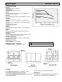
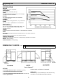
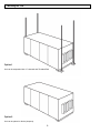
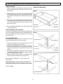
AAV1534
OPERATION AND
INSTALLATION MANUAL
For Models:
For Models:
HRV 1500 IFD
HRV
1500
SFD
HRV
1500
EFD
HRV 1500 SFDE
NOTE: ALTHOUGH SOME MODELS
DIFFER IN OPERATION, THE BASIC
INSTALLATION STEPS ARE SIMILAR.
APPLICATION WARNING !!!
It is always important to assess how the operation
of any Heat Recovery Ventilator may interact with
vented combustion equipment (i.e., Gas Furnaces,
Oil Furnaces, Wood Stoves, etc.)
NEVER install an Heat Recovery Ventilator in a
situation where the normal operation (including
defrost function), lack of operation or partial failure
may result in the backdrafting or improper functioning of vented combustion equipment!!
TO BE COMPLETED BY CONTRACTOR AFTER INSTALLATION
a
___________________________________________________________________
Installing Contractor
___________________________________________________________________
Telephone / Contact
___________________________________________________________________
Serial Number
_______________________________
Installation Date
_________________________________
Model
Do Not Attempt Installing Unit Without First Reading Entire Manual
Note: Due to ongoing research and product development, specifications,
ratings and dimensions are subject to change with notice
AL-04
9806
aav#1534
INTRODUCTION
TABLE OF CONTENTS
GENERAL
This Heat Recovery Ventilator (HRV) is designed
to provide fresh air into the building while exhausting an equal amount of stale air. During the winter
months, the incoming cold fresh air is warmed by
utilizing the heat recovered from the stale air before it is exhausted to the outdoors. During summer months when the indoor space is air conditioned, the Heat Recovery Ventilator will help in cooling the incoming fresh air with the stale air that is
being exhausted.
Cover & Installation Information...................... 1
These instructions are intended as a general guide
and do not supercede local codes in any way. Consult authorities who have jurisdiction before installing.
Roof Curb Assembly Instructions ................... 9
General ......................................................... 2
Engineering Data ........................................ 3-4
Function and Controls ................................... 5
Additional Features ....................................... 6
Servicing ....................................................... 7
Mounting the 1500 ......................................... 8
Roof Curb Detail ......................................... 10
Ducting ................................................... 11-12
The Integrated HVAC System ........................ 13
Pitot Tube Air Flow Balancing ........................ 14
Wiring Diagram .............................................15
Warranty ........................................................16
LEAVE WITH EQUIPMENT
Note: Due to ongoing research and product development,
specifications, ratings and dimensions are subject to
change without notice.
2
Model HRV 1500 SFD
Engineering Data
SPECIFICATIONS
AIRFLOW
1500cfm (705 L/s) at 1.0”wg ESP.
PERFORMANCE
65% effective at 1500 cfm (705 L/s).
CORES
Six patented aluminum heat recovery cores arranged for
efficient cross-flow ventilation.
MOTORS
Two single shaft ECM variable speed, 208/240V, 9.1 Amps, 1
ph, 1 hp.
BLOWERS
Two direct drive centrifugal blowers, one per airstream.
FILTERS
Two - 20” x 16” x 2” pleated filters in each airstream. MERV 6
efficiency.
CONNECTION DUCT SIZES
Four 18” x 18”
CABINET
20 gauge prepainted steel insulated 1” thick Elastomeric
insulation.
DRAIN
Two powder coated galvanized steel drain pans with 1/2”
O.D.drain connections.
MOUNTING
Unit to be set on support brackets hung by threaded rod type
apparatus. Brackets and rod not included.
CONTROLS & FUNCTION
Integrated microprocessor circuit board. 3 independently
adjustable motor speeds.
WEIGHT 480 lbs (218 kg)
SHIPPING WEIGHT 525 lbs (238 kg)
A
DIMENSIONS 1500SFD
inches
B
SFD 18
OPTIONS
C
D
E
F
G
H
I
J
L
2.5 18
12
37
66.75
18
18
10.25
2.5
44
All units conform to CSA and UL standards
28-879 Digital Electronic Timer - 20/40/60 min. (3 wire)
28-883 Dehumidistat Ventilation Control (DVC)
28-882 Remote Wall Mount Dehumidistat Control - 24 VAC only
28-885 3 Speed Control
3
WARRANTY
All units carry a 15 year warranty on the heat recovery
cores and a 2 year replacement parts warranty.
Model HRV 1500 SFDE
Engineering Data
SPECIFICATIONS
AIRFLOW
1500cfm (705 L/s) at 1.0”wg ESP.
PERFORMANCE
65% effective at 1500 cfm (705 L/s).
CORES
Six patented aluminum heat recovery cores arranged
for efficient cross-flow ventilation.
MOTORS
Two single shaft ECM variable speed, 208/240V,
9.1 Amps, 1 ph, 1 hp.
BLOWERS
Two direct drive centrifugal blowers, one per airstream.
FILTERS
Two - 20” x 16” x 2” pleated filters in each airstream.
MERV 6 efficiency.
DUCT CONNECTIONS
Two 19” x 16” to and from building under cabinet. Two
18” x 17” hoods included on side of cabinet with
washable screens.
CABINET
20 gauge powder coated steel insulated 1” thick Elastomeric insulation.
DRAIN
Two powder coated galvanized steel drain pans with 1/2” O.D. drain connections.
MOUNTING
Rooftop mounted on optional roof curb. (Part No. 28-125)
CONTROLS & FUNCTION
Integrated microprocessor circuit board. 3 independently adjustable motor speeds.
WEIGHT 480 lbs (218 kg)
SHIPPING WEIGHT 525 lbs (238 kg)
DIMENSIONS 1500SFDE
inches
A
SFDE 20
B
C
D
E
F
G
H
I
J
K
L
M
N
1.5
17
16.5
41
69.5
20
17
14.5
1.5
20
44
46.5
67
OPTIONS
All units conform to CSA and UL standards
28-879 Digital Electronic Timer - 20/40/60 min. (3 wire)
28-883 Dehumidistat Ventilation Control (DVC)
28-882 Remote Wall Mount Dehumidistat Control - 24 VAC only
28-885 3 Speed Control
4
WARRANTY
All units carry a 15 year warranty on the heat recovery
cores and a 2 year replacement parts warranty.
Model(s) HRV 1500 SFD / SFDE
Function & Controls
Basic Functions
Setup
Speed control is obtained by powering 24V to one of the
designated speed taps.
Select appropriate operational speed by installing the
jumper wire between one of the designated speed taps. (A
jumper wire is factory installed in the low speed position.)
Example:
Note:
A jumper between the R terminal and the G terminal will
result in low speed operation.
It is recommended to use the optional speed control Part
# 28-895 in order to obtain full fan speed control.
Optional Speed Control
Part #28 885
Micro Processor Board
Optional Remote
Dehumidistat
Part #28-882
Boosts unit to
high speed when
humidity is higher
than setpoint
Optional DET
Timer
Part #28-879
Optional DVC
Control
Part #28-883
Same as above
with On/OFF
switch and high
speed boost
switch
Boosts to high
speed for 20, 40,
60 minutes
5
Additional Features
HRV 1500 SFD or SFDE Speed Selection
electrical box. Both motors contain a separate ECM circuit
board to allow for independent adjustment of the motors.
The “adjust” tap will change the airflows on all three of the
speeds. Please note that this unit has been factory set to
obtain 1500CFM at 1" w.g. external static pressure. Adjustment of the high speed settings will produce higher flows
only in situations where the external static pressure is below 1" w.g.
The HRV 1500 SFD and HRV 1500 SFDE are equipped with
ECM motors that can be programmed to maintain various
different airflows. The HRV 1500 SFD and HRV 1500 SFDE
have three selectable speeds (High medium and low). Each
of these speeds can be further adjusted to obtain the desired
airflow.
This is done on the ECM circuit board located within the
6
Servicing
3. Remove filter divider panels (if only accessing from
one side).
4. Remove filters from behind filter divider panel.
5. Replace all filters. Ensure that filter divider panels are
reinserted into unit.
The HRV 1500 SFD and HRV 1500 SFDE are designed to be
serviceable from either side. If access to the unit will only
be available from one side, the unit must be set up accordingly. The unit is factory shipped to be serviced from the
front. (Blowers on the right when facing the unit. If servicing is only accessible from the other side follow the procedure below.
1. The Ebox must be removed from the front brackets and
mounted on the rear brackets provided on the other side
of the unit.
2. The filter divider panels must be removed and placed in
the unit so they can be removed from the opposite side.
3. The lower blower divider panel must be removed and
mounted in the unit from the other side.
Servicing Cores
1. Remove core service panel (one or both sides).
2. Slide cores out (regular core maintenance).
3. When placing the cores back into the unit, ensure that
there are no gaps between any of the cores.
Ensure all H channels are flush with the ends of the
cores before the core service panel is re-attached.
Servicing Blowers
Each panel on the unit can be removed by removing the
two bolts on the bottom.
1. Remove blower service panel (one or both sides)
2. Unscrew the 2 bolts that connect the blower to the blower
rails of the unit.
3. Remove all wiring to the motors.
4. Slide blower back and lift to remove blower assembly.
5. If access to the unit is not available from both sides,
remove the blower divider panel by removing the 8 bolts
holding this panel in place.
6. Repeat steps 2-4 with the other blower.
Servicing is easiest by removing the side panels on both
sides to gain access to either side of the unit.
Servicing Filters
1. Remove filter service panel (one or both sides).
2. Remove first set of filters.
7
Mounting the 1500
Option 1
Unit can be suspended with “U” channels and Threaded Rod
Option 2
Unit can be placed on blocks (sleepers)
8
Roof Curb Assembly Instructions for Model HRV 1500 SFDE
Frame Assembly
Roof Curb Assembly
1. Take one end piece (locking tabs) and one side piece
(slots). Stand both pieces vertically on the floor or roof.
See Figure 1.
2. Raise slightly the corner of the end piece (locking tabs)
and mate with side piece (slots), ensuring that lower locking tab with leading edge is through slot opening. See
Figure 2.
3. Push down on top edge of end piece. Ensure that all 3
of the locking tabs are feeding into each corresponding
slot. Once both pieces are flush, the process is complete. See Figure 3.
4. Drive one spike provided into wood nailer strips at each
corner. See Figure 3.
Frame Application and Location
This roof mounting frame provides necessary support when
the unit is installed. The frame can be installed directly on
deck having adequate structural strength or on roof supports under deck.
Securing the Frame
To ensure proper mating with unit, it is critical that mounting frame be squared to the roof, as follows:
1. With frame situated level in desired location on roof
trusses, tack weld one corner of frame.
2. Measure frame diagonally from one corner to the opposite corner. Repeat with the remaining two corners.
These dimensions must be equal for the frame to be
square.
3. It is extremely important to sight frame from all corners
to ensure that the frame is not twisted across top side.
Shim frame under any low sides.
4. After frame has been squared, straightened and
shimmed, weld or attach frame securely to roof.
MAX. SLOPE TOLERANCE: 1/16" per linear foot in
any direction.
Note specification of duct location on bottom of
HRV when positioning cross members (duct cavity).
See next page.
9
Roof Curb Detail for Model HRV 1500 SFDE
10
Ducting - General
Drains
Connect the drain pans in the bottom of the HRV to a drain
line fastened to the holes provided. Create a “P” trap to
prevent odors from being drawn through. Make sure the
drain line slopes down to drain properly and if this is not
possible a condensate pump will be required for removal
of the water. Note that stagnant water is a leading cause of
indoor air quality problems; confirm drainage after installation by pouring water into trays. Drain line must be installed
where it will not freeze.
The Ductwork System
A well designed ducting system will allow the HRV to operate at its maximum efficiency. Avoid the use of undersized
ducting and sharp radius bends and tees which can significantly increase the system pressure drop and reduce the
air flows.
NOTE: Fully insulated ducting with an integral vapor barrier must be used on all runs passing through unheated areas in order to avoid condensation problems and energy losses from the air streams.
* Consult local Codes
To minimize pressure drop and noise, galvanized metal
ducts sized for 1200 fpm (6.09 m/s) (maximum velocity)
are recommended. Keep ducting as short as possible and
use a minimum of elbows and tees. Connecting sections
and shorter runs may be flexible ducting one size larger
than the metal duct. Use flexible duct connectors at the
HRV to avoid noise transmission. All duct joints must be
secured with screws, rivets or duct sealant and sealed with
aluminum duct tape to prevent leakage.
The outside perimeter of the weatherhood must be caulked
to prevent leakage into the building. The design and size
of the weatherhoods or louvers chosen by the installer must
allow for adequate free area. Water and snow penetration
of the system is minimized when the airflow does not exceed 750 FPM (3.81m/s) free area velocity.
Ducting from the Weatherhoods
Galvanized sheet metal ducting with sufficient cross section with an integral single piece vapor barrier should be
used to connect the HRV to the weatherhoods. All ducting
must meet ULC Class 1 Fire Rating. A minimum R value of
insulation should be equal to 4 (RSI 0.75), or as stated in
local codes. A good bead of high quality caulking (preferably acoustical sealant) and taping with a high quality aluminum foil tape is recommended to seal the duct to both
the HRV and the weatherhood.
Warmside Ducting - General
Ducting from the HRV to different areas within the building
should be galvanized metal whenever possible. To minimize airflow losses in the ductwork system, all ducts should
be as short as possible and with as few bends or elbows as
possible. 45° elbows are preferred to 90° elbows, whenever possible. Use Y tees instead of 90° tees whenever
possible. All duct joints must be fastened securely and
wrapped with a quality duct tape to prevent leakage. We
recommend aluminum foil tape.
Outside Weatherhoods
The HRV 1500 SFDE is shipped with 2 weatherhoods inside
the cabinet which attach to the outer ends of the cabinet
using bolts provided. The HRV 1500 SFD requires exterior
hoods to be provided by the contractor.
NOTE: It is extremely important to design and install the
fresh air intake in an area where the hoods will
gather the freshest air, free from restriction.
Recommended:
•
•
•
•
No less than 10 ft. (3 m) apart from each other, or per
local code restriction.
At least 18 in. (46 cm) above ground level.
Away from sources of contaminants, such as automobile
exhaust fumes, gas meters, garbage containers, cooling
towers, etc.
Not exposed to prevailing winds, whenever reasonably
possible.
11
Ducting - Distribution
Stale Air Return System
Fresh Air Supply System
The stale air return system is used to draw air from the
points in the building where the worst air quality problems
occur. Balancing dampers and/or adjustable grilles are recommended on all return air lines which are used during
installation to help balance the “draw” from different areas
of the building. Note that the installation should incorporate the use of balancing dampers and/or adjustable grilles
on all return air lines coming back to the unit.
The fresh air supply ductwork from the HRV may be directly connected to the return air duct of the forced air system. When directly connected it is recommended that the
air handler blower be in constant operation to move the
fresh air about the building Also, it is advisable to include a
short length of fabric flex duct or other nonmetallic connector in this hard ducted line in order to keep the HRV acoustically isolated and separately grounded (electrically) from
the air handler. This will avoid a possible shock hazard to
service people if a short to ground develops in one of the
devices. It may be necessary to install a separate fresh air
supply ductwork system if the heating is other than forced
air.
Alternately, the stale air may be drawn directly from the
return air duct. When this system is used the air handler’s
blower will need to operate constantly when ventilation is
required. The exhaust takeoff connection must be at least
a meter from a directly connected HRV supply duct if both
are connected to the same duct run.
A damper located just prior to the HRV is required to balance the stale air exhausted with the fresh air supply
entering the building.
Return air suction points should be located at the opposite
side of the room to the fresh air inlet. The inlets may be
located in the ceiling or high on the walls and fitted with
inlet grilles.
Many commercial activities produce air contaminants in the
form of dusts, fumes, mists, vapors and gases. Contaminants should be controlled at the source so that they are
not dispersed through the building nor allowed to increase
to toxic concentration levels. The heat recovery ventilator
allows for economical operation of the HVAC system while
effectively removing contaminants from the space. In designing the exhaust portion of the system the exhaust grilles are
placed so as to remove the contaminants while not allowing
them to enter the breathing zone of the occupants.
When installing an HRV, the designer and installer should
be aware of local codes that may require smoke detectors
and/or firestats in the HVAC or HRV ductwork. Because an
HRV is designed to bring fresh air into the building, structures may require a supply voltage interrupt when smoke
or flame sensors are triggered or central fire alarm system
is activated.
Supply air grilles may be ceiling or high wall mounted. Avoid
locating incoming fresh air grilles that could cause a direct
draft on the occupants as the incoming air may be below
room temperature. A reheat duct heater can be installed to
improve occupant comfort. The use of balancing dampers
or adjustable grilles as supply air diffusers and air exhaust
grilles are recommended.
For contaminants that are lighter than air, grilles should be
located high on the wall. If contaminants are heavier than air,
a lower placement of the grilles will be required. Information
on a contaminants specific gravity and toxicity should be
available from the chemical data sheets.
12
The Integrated HVAC System
WARNING: This unit is a quiet, efficient, low pressure system. Special care and attention should be
given if connecting this unit to any other air handler that may draw more air than this unit is designed to accommodate.
but at a location closer to the air handler. The air handler
would have a constant running blower to effectively distribute the fresh air and remove the stale air. Balancing dampers would be located in both the HRV supply and exhaust
ducts between the return air plenum and the HRV.
In installations where it is satisfactory to provide general
exhaust from the space, the air to be exhausted may betaken directly from the return air plenum to the HRV as it is
drawn back to the air handler. Fresh air supplied by the
HRV is then introduced directly into the return air plenum
In installations where it is necessary or desirable to have
an extended ducting system, it is recommended to have a
qualified designer/engineer size and design the ducting
system to ensure optimum removal and distribution of air is
achieved.
Electrical Connections
System is 208/240V, 1 phase, 60 Hz. This unit meets all
local codes and requirements.
All electrical connections should be made by a qualified
electrician.
It is STRONGLY recommended that an electrical disconnect be installed prior to the HRV, and that it is turned off
and locked out before servicing the unit.
Two (2) knockouts are provided. One is to be used for line
voltage, and the other one for 24V control wires.
Balancing
The HRV 1500 SFD/SFDE have been programmed to provide
constant airflow on each airstream for external static pressures of up to 1” w.g.
Within this range, each airflow can be adjusted as described
on page 5. After 1” w.g. of external static pressure, the unit
acts as a regular system and the following balancing procedure should be used.
13
Pilot Tube Air Flow Balancing - Commercial
It is necessary to have balanced air flows in an HRV. The volume of
air brought in from the outside must equal the volume of air exhausted
by the unit. If the air flows are not properly balanced, then;
• The HRV may not operate at its maximum efficiency
• A negative or positive air pressure may occur
in the building
• The unit may not defrost properly
• Failure to balance HRV properly may void warranty
Excessive positive pressure may drive moist indoor air into the external walls of the building where it may condense (in cold weather)
and degrade structural components. May also cause key holes to
freeze up.
Excessive negative pressure may have several undesirable effects.
In some geographic locations, soil gases such as methane and radon gas may be drawn into the building through basement/ground
contact areas. Excessive negative pressure may also cause the
backdrafting of vented combustion equipment.
Read the Application Warning on the front of this manual!
Prior to balancing, ensure that:
1.
2.
3.
4.
5.
6.
7.
All sealing of the ductwork system has been completed.
All of the HRV’s components are in place and functioning properly.
Balancing dampers are fully open.
Unit is on HIGH speed.
Air flows in branch lines to specific areas of the house should
be adjusted first prior to balancing the unit. A smoke pencil used
at the grilles is a good indicator of each branch line’s relative air
flow.
After taking readings of both the stale air to the HRV duct and
fresh air to the house duct, the duct with the lower CFM ([L/s]
velocity) reading should be left alone, while the duct with the
higher reading should be dampered back to match the lower
reading.
Return unit to appropriate fan speed for normal operation
The Pitot tube should be connected to a magnehelic gauge or other
manometer capable of reading from 0 to 0.25 in. (0-62 Pa) of water,
preferably to 3 digits of resolution. The tube coming out of the top of
the pitot is connected to the high pressure side of the gauge. The
tube coming out of the side of the pitot is connected to the low pressure or reference side of the gauge. Insert the Pitot tube into the
duct; pointing the tip into the airflow.
For general balancing it is sufficient to move the pitot tube around in
the duct and take an average or typical reading. Repeat this procedure in the other (supply or return) duct. Determine which duct has
the highest airflow (highest reading on the gauge). Then damper that
airflow back to match the lower reading from the other duct. The
flows should now be balanced. Actual airflow can be determined
from the gauge reading. The value read on the gauge is called the
velocity pressure. The Pitot tube comes with a chart that will give the
air flow velocity based on the velocity pressure indicated by the gauge.
This velocity will be in either feet per minute or meters per second.
To determine the actual airflow, the velocity is multiplied by the cross
sectional area of the duct being measured.
The accuracy of the air flow reading will be affected by how close to
any elbows or bends the readings are taken. Accuracy can be increased by taking an average of multiple readings as outlined in the
literature supplied with the Pitot tube.
BALANCING PROCEDURE
The following is a method of field balancing an HRV using a Pitot
tube, advantageous in situations when flow stations are not installed
in the ductwork. Procedure should be performed with the HRV on
high speed.
The first step is to operate all
mechanical systems on high
speed, which have an influence
on the ventilation system, i.e. the
HRV itself and the forced air furnace or air handler if applicable.
This will provide the maximum
pressure that the HRV will need
to overcome, and allow for a
more accurate balance of the
unit.
Drill a small hole in the duct
(about 3/16"), three feet downstream of any elbows or bends,
and one foot upstream of any elbows or bends. These are recommended distances but the
actual installation may limit the
amount of straight duct.
14
Wiring Diagram
15
Commercial
Heat Recovery Ventilators
♦ TWO YEAR LIMITED WARRANTY - 15 YEAR CORE WARRANTY
AMERICAN ALDES VENTILATION CORPORATION warrants to the original purchaser of the Commercial ALDES HRV model and accessories referred to below, to be free from manufacturing defects.
This Warranty is person to ALDES and is in effect from the date of the original purchase for a period
of two years, save and except that a 15 YEAR WARRANTY is given to the ALDES HRV core should it
develop a condensation leak or become perforated due to corrosion caused by normal use.
Damage resulting from all other causes, including but not limited to: lightning, hurricane, tornado,
earthquake or any other acts of God; improper installation, modification, alteration or misuse of the ALDES
HRV or its operation in a manner contrary to the instructions accompanying the unit at the time of sale;
accidental or intentional damage, neglect, improper care, or other failure by the owner to provide reasonable
and necessary maintenance of the product; any attempt at repair by an unauthorized service representative or
not in accordance with this Warranty; or any other causes beyond the control of ALDES, are excluded from
this Warranty.
If you feel that the ALDES HRV you purchased is not free from manufacturing defects please contact
AMERICAN ALDES VENTILATION CORPORATION, 4537 Northgate Court, Sarasota, FL, 941-351-3441 - or
fax: 941-351-3442 to find the name of your nearest dealer in order to repair the product. The labor required to
install any replacement part(s) shall be dealt with at the option of the customer in either of the following ways:
a.
The customer may supply labor at their own expense:
or
b.
If the product was purchased from a dealer, then the dealer will supply
labor at cost to the customer.
ALDES reserves the right to replace the entire unit or to refund the original purchase price in lieu of repair.
ALDES MAKES NO EXPRESS WARRANTIES, EXCEPT FOR THOSE THAT ARE SET FORTH HEREIN
AND SHALL NOT BE LIABLE FOR ANY INCIDENTAL, SPECIAL OR CONSEQUENTIAL DAMAGES
WITH RESPECT TO ALDES HRV’S COVERED BY THIS WARRANTY. ALDES COMPLETE LIABILITY AND THE OWNER’S EXCLUSIVE REMEDY BEING LIMITED TO REPAIR OR REPLACEMENT
ON THE TERMS STATED HEREIN. ANY IMPLIED WARRANTIES, INCLUDING BUT NOT LIMITED
TO THE IMPLIED WARRANTY OF MERCHANTABILITY AND OF FITNESS FOR ANY PARTICULAR
PURPOSE, ARE EXPRESSLY EXCLUDED.
NO PERSON IS AUTHORIZED TO CHANGE THE WARRANTY IN ANY WAY OR GRANT ANY OTHER
WARRANTY UNLESS SUCH CHANGES ARE MADE IN WRITING AND SIGNED BY AN OFFICER OF
ALDES.
MODEL NO.:______________________________
UNIT SERIAL NO.:_________________________
INSTALLED BY:________________________________________________________________________
DATE:___________________________________
16