1
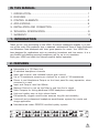
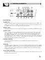
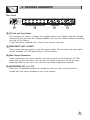
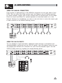
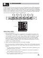
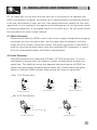
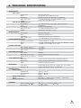
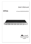
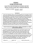
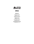
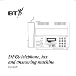
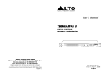
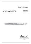
R
LTO
OWNER'S MANUAL
HPA6
6-CHANNEL HEADPHONE AMPLIFIER
www.altoproaudio.com
Version 2.4 SEPTEMBER 2007
English
IMPORTANT SAFETY INSTRUCTION
CAUTION
RISK OF ELECTRIC SHOCK
DO NOT OPEN
TO REDUCE THE RISK OF ELECTRIC SHOCK
PLEASE DO NOT REMOVE THE COVER OR
THE BACK PANEL OF THIS EQUIPMENT.
THERE ARE NO PARTS NEEDED BY USER
INSIDE THE EQUIPMENT. FOR SERVICE,
PLEASE CONTACT QUALIFIED SERVICE
CENTERS.
WARNING
To reduce the risk of electric shock
and fire, do not expose this equipment
to moisture or rain.
Dispose of this product should
not be placed in municipal waste
and should be separate collection.
11. Move this Equipment only with a cart,
stand, tripod, or bracket,
This symbol, wherever used, alerts you to the
specified by the
presence of un-insulated and dangerous voltages
manufacturer, or
within the product enclosure. These are voltages that
sold with the
may be sufficient to constitute the risk of electric
Equipment. When
shock or death.
a cart is used, use
This symbol, wherever used, alerts you to
caution when
important operating and maintenance instructions.
moving the cart /
Please read.
equipment
Protective Ground Terminal
combination to
AC mains (Alternating Current)
avoid possible
Hazardous Live Terminal
injury from tip-over.
ON: Denotes the product is turned on.
12. Permanent hearing loss may be caused by
OFF: Denotes the product is turned off.
exposure to \ extremely high noise levels.
CAUTION
The US. Government's Occupational Safety
Describes precautions that should be observed to
and Health Administration (OSHA) has
prevent damage to the product.
specified the permissible exposure to noise
1. Read this Manual carefully before operation.
level.
2. Keep this Manual in a safe place.
These are shown in the following chart:
3. Be aware of all warnings reported
with this symbol.
HOURS X DAY SPL EXAMPLE
4. Keep this Equipment away from water and
90 Small gig
8
moisture.
92 train
6
5. Clean it only with dry cloth. Do not use
95 Subway train
4
solvent or other chemicals.
97 High level desktop monitors
3
6. Do not damp or cover any cooling opening.
100 Classic music concert
2
Install the equipment only in accordance with
the Manufacturer's instructions.
102
1,5
105
1
7. Power Cords are designed for your safety. Do
110
0,5
not remove Ground connections! If the plug
does not fit your AC outlet, seek advice from
0,25 or less 115 Rock concert
a qualified electrician. Protect the power
According to OSHA, an exposure to high SPL in
cord and plug from any physical stress to
excess of these limits may result in the loss of
avoid risk of electric shock. Do not place
heat. To avoid the potential damage of heat, it is
heavy objects on the power cord. This could
cause electric shock or fire.
recommended that Personnel exposed to
equipment capable of generating high SPL use
8. Unplug this equipment when unused for long
hearing protection while such equipment is
periods of time or during a storm.
under operation.
9. Refer all service to qualified service personnel
The apparatus shall be connected to a mains
only. Do not perform any servicing other than
those instructions contained within the
socket outlet with a protective earthing
User's Manual.
connection.
10. To prevent fire and damage to the product,
use only the recommended fuse type as
indicated in this manual. Do not short-circuit
the fuse holder. Before replacing the fuse,
make sure that the product is OFF and
disconnected from the AC outlet.
The mains plug or an appliance coupler is used
as the disconnect device, the disconnect device
shall remain readily operable.
IN THIS MANUAL:
1. INTRODUCTION..............................................................................1
2. FEATURES.....................................................................................1
3. CONTROL ELEMENTS....................................................................2
4. APPLICATIONS...............................................................................5
5. INSTALLATION AND CONNECTION..................................................7
6. TECHNICAL SPECIFACATION...........................................................9
7. WARRANTY...................................................................................10
1. INTRODUCTION
Thank you for your purchasing of the HPA6, 6-channel headphone amplifier. It is just
one of the many Alto products that a talented, multinational Team of Audio Engineers
and Musicians have developed with their great passion for music. Your HPA6 has
been designed for applications such as recording, broadcast and Live events. It is a
very flexible tool allowing personal headphone mix for up to six musicians.
Enjoy your HPA6 and read this Manual carefully before operation!
2. FEATURES
Mountable in a 19" Rack Unit
6 individual headphone channels
Input gain control, and individual output gain control
Up to 3 headphone outputs per channel for a total of 18 headphones
Direct In and Headphone Output on the front panel for easy operation, when
mounted in a rack
Input and Output Level Led Meter
Balance Control to mix up the Main In and the Aux In signal
Main Outputs for linking additional HPA6 headphone amplifiers
High-end quality even at high volume levels
Exceptionally rugged construction ensures long life and durability
Universal and professional headphone amplification system for studio and
stage application
Manufactured under QS9000 certified quality system
INPUT LEVEL(dBu)
24
18
12
6
0
6
LTO
DIRECT IN
3
OUTPUT LEVEL(dBu)
12
18
24 0
2
12 CLIP
L MUTE R
3
2
R
1
MAININ
AUX
BALANCED
5
1
6
0
INPUT GAIN
MAIN SECTION
3
OUTPUT LEVEL(dBu)
4
24 0
5
2
12 CLIP
L MUTE R
1
3
OUTPUT LEVEL(dBu)
4
24 0
5
2
12 CLIP
L MUTE R
1
3
OUTPUT LEVEL(dBu)
4
24 0
5
2
12 CLIP
L MUTE R
1
3
OUTPUT LEVEL(dBu)
4
24 0
5
2
12 CLIP
L MUTE R
1
3
OUTPUT LEVEL(dBu)
4
24 0
5
2
12 CLIP
L MUTE R
1
4
5
4
AUX IN
6
0
OUTPUT GAIN
HEADPHONE OUT
MAININ
AUX
BALANCED
AUX IN
6
0
OUTPUT GAIN
HEADPHONE OUT
MAININ
AUX
BALANCED
AUX IN
6
0
OUTPUT GAIN
HEADPHONE OUT
MAININ
AUX
BALANCED
AUX IN
6
0
OUTPUT GAIN
HEADPHONE OUT
MAININ
AUX
BALANCED
AUX IN
6
0
OUTPUT GAIN
HEADPHONE OUT
MAININ
AUX
BALANCED
AUX IN
MONO
MONO
MONO
MONO
MONO
MONO
STEREO
STEREO
STEREO
STEREO
STEREO
STEREO
CHANNEL 1
CHANNEL 2
CHANNEL 3
CHANNEL 4
CHANNEL 5
CHANNEL 6
HPA6
6
0
OUTPUT GAIN
HEADPHONE OUT
ON
OFF
6-CHANNEL
HEADPHONE
AMPLIFIER
POWER
1
SP
OT
L
IG
3. CONTROL ELEMENTS
HT
5
3
INPUT LEVEL(dBu)
24
18
12
6
0
6
18
DIRECT IN
9
24 0
10
3
2
12 CLIP
L MUTE R
3
LTO
5
OUTPUT LEVEL(dBu)
12
2
R
11
4
5
1
4
MAININ
AUX
BALANCED
5
1
AUX IN
6
0
OUTPUT GAIN
HEADPHONE OUT
MONO
6
0
INPUT GAIN
STEREO
MAIN SECTION
1
2
CHANNEL 1
7
6
4
8
MAIN SECTION:
1 DIRECT IN
You can use this socket to feed and additional stereo signal into your HPA6. This
socket is in "priority". It means that when you insert the jack, the signal fed into
the MAIN input on the rear panel will be disconnected.
2 INPUT GAIN
This knob controls the level of the signal applied to the MAIN or DIRECT IN inputs.
3 INPUT LEVEL
This Led Meter informs you about the level of the input signal. The range goes
from 24 dBu to +18 dBu. For the best quality of input signal the operating
leds should be those from +6 to +18 dBu. The CLIP led should light up only
occasionally. If CLIP led is always on, you must reduce the input level through the
input gain control. If only -18 and -12 dBu leds are operating, you will experience
a bad S/N ratio and increase the input level.
CHANNEL SECTION
There are 6 identical channels on your HPA6 with identical functions and
performance.
4 AUX IN
This stereo input is useful when you want to feed an additional signal with the signals
applied to MAIN or DIRECT IN inputs. If you have a stereo signal depress the MONO
switch. If you have a mono signal, press the MONO switch if you want such signal
to appear on both ears.
5 L&R MUTE SWITCHES
Through these switches you can mute the respective input signals one at a time
or both at the same time.
2
SP
OT
L
IG
3. CONTROL ELEMENTS
HT
6 MODE SWITCH
Depress the switch if you want to hear a stereo signal. Press it again if you
want to hear a mono signal.
7 MONO Led:
When the MODE switch is engaged this Led will light up.
8 HEADPHONE OUT
This connector is wired in parallel with the correspondent output connector on
the rear panel. It is useful to connect headphones when your HPA6 is installed
into a rack.
9 BALANCE CONTROL
This knob has a double function. When the AUX IN input is not in use it will
regulate the stereo imaging of the input signal. When a signal is fed into the
AUX IN input, the balance control will regulate the ratio of MAIN IN (or
DIRECT IN) and AUX IN input signals.
10 OUTPUT GAIN
This knob controls the output volume of the channel. Both right and left signals
are regulated at the same time.
11 OUTPUT LEVEL
This 4-digit led meter tells you about the level of the output signal, and the
range goes from -24 dBu to +12 dBu. When the Clip LED lights up, please
turn down the Output Gain Control to avoid any distortion.
3
SP
OT
L
IG
3. CONTROL ELEMENTS
HT
Rear Panel
Rated Power
Consumption 40W
FUSE:
210-240V: T315mAL 250VAC
95-120V: 500mA 250VAC
REPLACE FUSE WITH
CORRECT TYPE ONLY
Apparaten skall anslutas
till jordat uttag nar den
ansluts till ett natverk
A101
DESIGNED IN ITALY
MADE IN CHINA
12
TIP/PIN 2
RING/PIN 3
SLEEVE/PIN 1
TIP:
L- CHANNEL
RING:
R- CHANNEL
MIN. LOAD
100OHMS
TIP/PIN 2
RING/PIN 3
SLEEVE/PIN 1
TIP/PIN 2
RING/PIN 3
SLEEVE/PIN 1
TIP/PIN 2
RING/PIN 3
SLEEVE/PIN 1
2
2
1
HEADPHONE OUT 6 HEADPHONE OUT 5 HEADPHONE OUT 4 HEADPHONE OUT 3 HEADPHONE OUT 2 HEADPHONE OUT 1
15
MAIN OUTPUT RIGHT
MAIN OUTPUT LEFT
14
1
3
3
MAIN INPUT LEFT
MAIN INPUT RIGHT
13
12 AC Inlet and Fuse Holder
This connector is used to connect the supplied power cord. Please check the Voltage
accepted by the unit and the Voltage available from your AC sockets before connecting
the unit to the Mains.
If the fuse blows, replaced with a fuse of the correct type only.
13 MAIN INPUT LEFT & RIGHT
These connectors are used to input the stereo signal. You can input the main signal
via the balanced 1/4" TRS phone jack or XLR connector.
14 Main Output Connectors
These connectors are used to output the stereo signal via the balanced 1/4" TRS
phone jack or XLR connector. You can also use these connectors to link as many
additional HPA6 as you wish if you need to use many headphones channels.
15 HEADPHONE OUT (1 to 12)
These are 12 additional outputs for headphone (two for every channel) wired in
parallel with the output available on the front channel.
4
4. APPLICATIONS
USING THE MAIN IN CONNECTORS
First connect a signal source to the MAIN IN connectors on the rear panel of your
HPA6. Set the Input Gain (Main section) and the Balance control (Channel section)
on center position. Output gain of each channel must be turned down at this stage.
Check the input level Meter for optimal operation as described earlier on in this
Manual. Connect the headphones you want to use and start to raise the output gain
of each channel for the desired listening volume.
INPUT LEVEL(dBu)
24
18
12
6
0
6
DIRECT IN
3
OUTPUT LEVEL(dBu)
12
24 0
18
2
12 CLIP
L MUTE R
3
2
R
LTO
3
OUTPUT LEVEL(dBu)
4
24 0
5
1
2
12 CLIP
L MUTE R
3
OUTPUT LEVEL(dBu)
4
24 0
2
12 CLIP
L MUTE R
5
1
3
OUTPUT LEVEL(dBu)
4
24 0
5
1
2
12 CLIP
L MUTE R
3
OUTPUT LEVEL(dBu)
4
24 0
5
1
2
12 CLIP
L MUTE R
3
OUTPUT LEVEL(dBu)
4
24 0
5
1
2
12 CLIP
L MUTE R
4
5
1
4
MAININ
AUX
BALANCED
5
1
AUX IN
6
0
INPUT GAIN
6
0
OUTPUT GAIN
HEADPHONE OUT
MAININ
AUX
BALANCED
AUX IN
6
0
OUTPUT GAIN
HEADPHONE OUT
MAININ
AUX
BALANCED
AUX IN
6
0
OUTPUT GAIN
HEADPHONE OUT
MAININ
AUX
BALANCED
AUX IN
6
0
OUTPUT GAIN
HEADPHONE OUT
MAININ
AUX
BALANCED
AUX IN
6
0
OUTPUT GAIN
HEADPHONE OUT
MAININ
AUX
BALANCED
AUX IN
MONO
MONO
MONO
MONO
MONO
MONO
STEREO
STEREO
STEREO
STEREO
STEREO
STEREO
MAIN SECTION
CHANNEL 1
CHANNEL 2
CHANNEL 3
CHANNEL 4
CHANNEL 5
HPA6
6
0
OUTPUT GAIN
HEADPHONE OUT
ON
OFF
6-CHANNEL
HEADPHONE
AMPLIFIER
POWER
CHANNEL 6
TO MAIN INPUT
DIGITAL MIXER
USING THE AUX IN INPUTS
You can playback a signal and feed in additional vocals through a microphone and
mixer/preamplifier connected into the AUX IN socket. Use the balance control to give
the vocalist the desired mix in between his voice and the playback signal. Use the
OUTPUT GAIN control to regulate the overall desired volume.
INPUT LEVEL(dBu)
24
18
12
6
0
6
R
LTO
DIRECT IN
3
OUTPUT LEVEL(dBu)
12
18
24 0
2
12 CLIP
L MUTE R
3
2
1
3
OUTPUT LEVEL(dBu)
4
24 0
2
12 CLIP
L MUTE R
5
1
3
OUTPUT LEVEL(dBu)
4
24 0
5
2
12 CLIP
L MUTE R
1
3
OUTPUT LEVEL(dBu)
4
24 0
5
2
12 CLIP
L MUTE R
1
3
OUTPUT LEVEL(dBu)
4
24 0
5
2
12 CLIP
L MUTE R
1
3
OUTPUT LEVEL(dBu)
4
24 0
5
2
12 CLIP
L MUTE R
1
4
5
4
5
1
6
0
INPUT GAIN
MAIN SECTION
6
0
MAININ
AUX
BALANCED
OUTPUT GAIN
AUX IN
HEADPHONE OUT
MONO
6
0
MAININ
AUX
BALANCED
OUTPUT GAIN
AUX IN
HEADPHONE OUT
MONO
6
0
MAININ
AUX
BALANCED
OUTPUT GAIN
AUX IN
HEADPHONE OUT
MONO
6
0
MAININ
AUX
BALANCED
OUTPUT GAIN
AUX IN
HEADPHONE OUT
MONO
6
0
MAININ
AUX
BALANCED
OUTPUT GAIN
AUX IN
HEADPHONE OUT
MONO
6
0
MAININ
AUX
BALANCED
OUTPUT GAIN
AUX IN
HEADPHONE OUT
MONO
STEREO
STEREO
STEREO
STEREO
STEREO
STEREO
CHANNEL 1
CHANNEL 2
CHANNEL 3
CHANNEL 4
CHANNEL 5
CHANNEL 6
HPA6
ON
OFF
6-CHANNEL
HEADPHONE
AMPLIFIER
POWER
AUX SEND
TO MAIN INPUT
R
2
1
3
2
1
3
L-6
LTO
6-CHANNEL MIXING CONSOLE
WITH DIGITAL EFFECTS
DIGITAL MIXER
L-6 MIXER
5
4. APPLICATIONS
Through the AUX IN inputs you can also use the 6 channels of your HPA6 independently
to give individual mixers to 6 different musicians. Connect the Aux Sends or Subgroups
outputs directly to the AUX IN input of your HPA6. You need a mixer with 6 Aux sends
output or with 6 subgroups such as the Alto L Series mixer. Now rotate the BALANCE
control on your HPA6 fully to the left. IN this way you will exclude the MAIN signal and
only the AUX IN signal will be sent to the headphones.
INPUT LEVEL(dBu)
24
18
12
6
0
6
LTO
DIRECT IN
3
OUTPUT LEVEL(dBu)
12
18
24 0
2
12 CLIP
L MUTE R
3
2
R
MAININ
AUX
BALANCED
5
6
0
INPUT GAIN
MAIN SECTION
3
OUTPUT LEVEL(dBu)
4
24 0
5
1
2
12 CLIP
L MUTE R
3
OUTPUT LEVEL(dBu)
4
24 0
5
1
2
12 CLIP
L MUTE R
1
3
OUTPUT LEVEL(dBu)
4
24 0
5
2
12 CLIP
L MUTE R
3
OUTPUT LEVEL(dBu)
4
24 0
2
12 CLIP
L MUTE R
5
1
1
3
OUTPUT LEVEL(dBu)
4
24 0
5
2
12 CLIP
L MUTE R
1
4
5
4
1
AUX IN
6
0
OUTPUT GAIN
HEADPHONE OUT
MAININ
AUX
BALANCED
AUX IN
6
0
OUTPUT GAIN
HEADPHONE OUT
MAININ
AUX
BALANCED
AUX IN
6
0
OUTPUT GAIN
HEADPHONE OUT
MAININ
AUX
BALANCED
AUX IN
6
0
OUTPUT GAIN
HEADPHONE OUT
MAININ
AUX
BALANCED
AUX IN
6
0
OUTPUT GAIN
HEADPHONE OUT
MAININ
AUX
BALANCED
AUX IN
MONO
MONO
MONO
MONO
MONO
MONO
STEREO
STEREO
STEREO
STEREO
STEREO
STEREO
CHANNEL 1
CHANNEL 2
AUX IN1
AUX IN 2
CHANNEL 3
AUX IN 3
CHANNEL 4
CHANNEL 5
AUX IN 4
R
LTO
AUX IN 5
HPA6
6
0
OUTPUT GAIN
HEADPHONE OUT
ON
OFF
CHANNEL 6
6-CHANNEL
HEADPHONE
AMPLIFIER
POWER
AUX IN 6
L-12
12 CHANNEL COMPACT INTEGRATED LIVE SOUND MIXER
WITH
DIGITAL EFFECTS
L-12 MIXER
SOME FINIAL NOTES
1. RACK MOUNTING
The most secure mounting is on a universal 19" rack available from various rack
manufacturers or your Dealer. The HPA6 6-Channel Headphone Amplifier fits into
one standard 19" rack unit of space. Please allow at least an additional 4" depth
for the connectors on the rear panel. Be sure that there is enough air space
around the unit for sufficient ventilation and please do not place your HPA6 the
6-Channel Headphone Amplifier close to high temperature devices such as power
amplifiers etc. to avoid overheating.
2. USING MULTIPLE HEADPHONES ON THE SAME CHANNEL
Each channel provides 3 Headphone Outputs. These jacks are all parallel connected.
For best results getting from the HPA6, please note the impedance information as
following:
1. For each channel connecting with 1 headphone, the minimum impedance of the
headphone should be 100 ohms.
2. For each channel connecting with 2 headphones, the minimum impedance of
each headphone should be 200 ohms.
3. For each channel connecting with 3 headphones, the minimum impedance of
each headphone should be 300 ohms.
6
5. INSTALLATION AND CONNECTION
Ok, you have got to this point and you are now in the position to operate your
HPA6 successfully. However, we advise you to read carefully the following section
to be the real master of your own mix. Not paying attention enough to the input
signal level, to the routing of the signal and the assignment of the signal will result
in unwanted distortion, a corrupted signal or no sound at all. So you should follow
this procedure for every single channel:
4.1 Mains Connection
Please ensure that the HPA6 is set to the correct supply voltage before plugging
the power cord into the wall outlet, use the same fuse as marked on the fuse
holder at the AC power connection socket. The mains connection of the HPA6 is
made by using the enclosed mains cord and a standard IEC receptacle. It meets
all of the international safety certification requirements.
4.2 Audio Connection
The HPA6 presents with balanced XLR and 1/4" TRS phones jack. It can be
interfaced by several ways to support a variety of applications without any
signal loss. The defective wiring may degrade the performance of HPA6, so
please use good quality screened audio cables only. Please follow the guide
below to interface HPA6 without experiencing any noise or signal loss.
For 1/4" Phone jack
+
-
+
Ring
Tip
+
Tip
Tip
Ring
Sleeve
Sleeve
Sleeve
TRS Type Balanced
TS Type Unbalanced
TRS Type Unbalanced
For XLR Connector
Pin2 (+)
Pin3 (-)
(Linked to Pin1 manually,
Pin1 (
)
XLR Type Unbalanced
Pin2 (+)
Pin3 (-)
)
Pin1 (
)
XLR Type balanced
7
5. INSTALLATION AND CONNECTION
Balanced
TIP RING SLEEVE
SLEEVE RING TIP
Tip
Ring
Sleeve
1
2
3
3
3
1
1
2
2
1
3
2
TIP RING SLEEVE
Tip
Ring
Sleeve
1
2
3
Tip
Ring
Sleeve
1
2
3
Unbalanced
1
3
2
TIP RING SLEEVE
1
2
3
Tip
1
2
3
1
Tip
Ring
Sleeve
3
2
TIP SLEEVE
2
3
1
Sleeve
1
2
3
Tip
TIP SLEEVE
TIP RING SLEEVE
SLEEVE TIP
SLEEVE RING TIP
Sleeve
Tip
Ring
Sleeve
Tip
TIP RING SLEEVE
Tip
Ring
Sleeve
1
1
Tip
Tip
Ring
Sleeve
Sleeve
3
3
Screen
Sleeve
TIP SLEEVE
2
2
Centre
1
2
3
Centre
Screen
Centre
Screen
1
2
3
8
6. TECHNICAL SPECIFICATION
AUDIO INPUT
Main Input
XLR and 1/4" jack
RF filtered, servo balanced input
50 kOhms balanced, 25 kOhms unbalanced
+21 dBu balanced and unbalanced(unity gain)
typ.40 dB, >55 dB @ 1kHz
Connectors
Type
Impedance
Max. input level
CMRR
AUX IN and DIRECT IN input
Connectors
Type
Impedance
Max. Input level
CMRR
1/4" TRS (tip=left, ring=right, sleeve=ground)
Unbalanced
25 kOhms Unbalanced
+21 dBu unbalanced(unity gain)
typ,40 dB, >55 dB @ 1 kHz
AUDIO OUTPUT
Connectors
Type
Impedance
Max. output level
SYSTEM SPECIFICATIONS
Frequency response
Noise
THD
POWER AMPLIFIER
Max. Output power
Min. Output impedance
MAX. Gain
XLR and 1/4" Jack
Balanced /Unbalanced
Dependent on the input impedance
+21 dBu Balanced and Unbalanced
10 Hz to 50 kHz,+/-3 dB
>90 dB, Unweighted, 22 Hz to 22 kHz(>95 dB@+4 dBu)
0.005% typ.@+4 dBu, 1kHz, Gain 1
+21 dBm
100 Ohms
+20dB
FUNCTION CONTROLS
Input level
Balanced per channel
Output level per channel
FUNCTION SWITCHES
Left mute
Right mute
Mode
INDICATORS
Input level
Output level
POWER SUPPLY
Mains voltage
USA/Canada
U.K./Australia
Europe
Power consumption
Fuse
Mains connection
variable
mix between aux and main signal
variable
mutes the left signal of the respective channel
mutes the right signal of the respective channel
switches channel to mono
8-digit LED display: -24/-18/-12/-6/0/+6/+12/+18 dBu
4-digit LED display: -24/0/+12 dBu/CLIP
120 V , 60 Hz
240 V~, 50 Hz
230 V~, 50 Hz
40 W
95-120 V~: T500 mA L/210-240 V~: T315 mA L
Standard IEC receptacle
PHYSICAL
Dimension(W
Net weight
D
H)
483 217 44 mm(19" 8.54" 1.7")
2.9 kg(6.39 lbs)
9
7. WARRANTY
1. WARRANTY REGISTRATION CARD
To obtain Warranty Service, the buyer should first fill out and return the enclosed
Warranty Registration Card within 10 days of the Purchase Date.
All the information presented in this Warranty Registration Card gives the
manufacturer a better understanding of the sales status, so as to provide a
more effective and efficient after-sales warranty service. Please fill out all the
information carefully and genuinely, miswriting or absence of this card will void
your warranty service.
2. RETURN NOTICE
2.1 In case of return for any warranty service, please make sure that the
product is well packed in its original shipping carton, and it can protect your
unit from any other extra damage.
2.2 Please provide a copy of your sales receipt or other proof of purchase with
the returned machine, and give detail information about your return address
and contact telephone number.
2.3 A brief description of the defect will be appreciated.
2.4 Please prepay all the costs involved in the return shipping, handling and
insurance.
3. TERMS AND CONDITIONS
3.1 LTO warrants that this product will be free from any defects in materials
and/or workmanship for a period of 1 year from the purchase date if you
have completed the Warranty Registration Card in time.
3.2 The warranty service is only available to the original consumer, who purchased
this product directly from the retail dealer, and it can not be transferred.
3.3 During the warranty service, LTO may repair or replace this product at its
own option at no charge to you for parts or for labor in accordance with the
right side of this limited warranty.
3.4 This warranty does not apply to the damages to this product that occurred
as the following conditions:
Instead of operating in accordance with the user's manual thoroughly, any abuse
or misuse of this product.
Normal tear and wear.
The product has been altered or modified in any way.
Damage which may have been caused either directly or indirectly by another
product / force / etc.
Abnormal service or repairing by anyone other than the qualified personnel or
technician.
And in such cases, all the expenses will be charged to the buyer.
3.5 In no event shall LTO be liable for any incidental or consequential damages.
Some states do not allow the exclusion or limitation of incidental or
consequential damages, so the above exclusion or limitation may not apply to
you.
3.6 This warranty gives you the specific rights, and these rights are compatible
with the state laws, you may also have other statutory rights that may vary
from state to state.
10
SEIKAKU TECHNICAL GROUP LIMITED
NO. 1, Lane 17, Sec. 2, Han Shi West Road, Taichung 40151, Taiwan
http://www.altoproaudio.com Tel: 886-4-22313737
email: [email protected] Fax: 886-4-22346757
All rights reserved to ALTO. All features and content might be changed
without prior notice. Any photocopy, translation, or reproduction of part of this
manual without written permission is forbidden. Copyright c 2007 Seikaku Group
NF00893-2.4