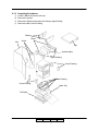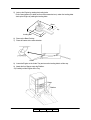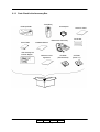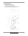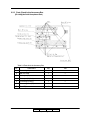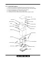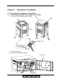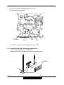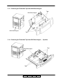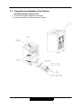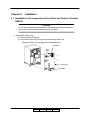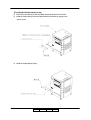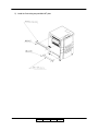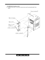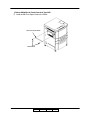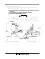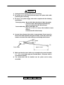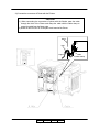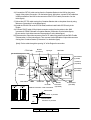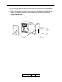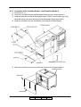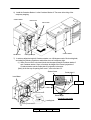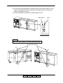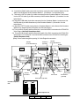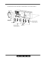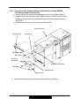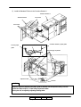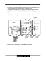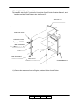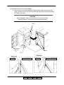
1
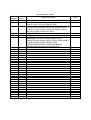
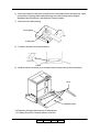
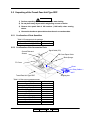
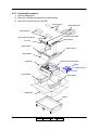
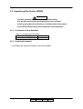
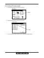
Installation
Manual
© 2005 Ricoh Printing Systems, Ltd.
March, 2007
N904116
Revision Table for manual
Rev. for
Manual
00
01
Machine
Rev.
-
02
U5
03
04
05
-
06
07
-
Page No.(Contents)
Date
First Edition
Table of Contents ii(01) 2-3(01), 2-4(01), 2-5(01),
4-4(01), 4-15(01), 5-1(01), 5-2(00) to 5-7(00)
RoHS Compliance. 2-4(02),2-5(02),2-7(01) to 2-10(01),2-16(01)
3-2(01),3-4(01),3-9(01) to 3-11(01),3-15(01),4-5(01),4-7(01),
4-10(01) to 4-12(01),4-19(01),4-21(01) to 4-23(01),4-25(01),
4-27(01) to 4-29(01),4-32(01) to 4-35(01),
2-4(03),2-5(03)
5-8(00)
Table of Contents i(01),ii(02),1-1(01),1-2(01) ,4-1(01), 4-37(02),
Added pages : 2-17(00),2-18(00),2-19(00),3-16(00) ,
4-5(00),4-14(00),4-15(00),4-16(00),4-17(00),4-18(00),4-19(00),
4-20(00),4-44(00),4-45(00),4-46(00),4-47(00),
4-48(00),4-49(00),4-50(00), 4-51(00),Appendix9(00),
Appendix10(00),Appendix11(00), Appendix12(00)
2-17(01),4-17(01),4-18(01)
2-17(02),2-18(01) ,4-17(02),4-18(02), 4-48(01),4-49(01)
May, 23. ’05
Oct, 21. ’05
Mar, 24. ‘06
Mar, 5. ‘07
Jan,22.’08
Mar,28.’08
Apl, 10.’08
Jun, 18.’08
© 2005 Ricoh Printing Systems, Ltd. All rights reserved.
No part of this document may be reproduced without the expressed permission of Ricoh Printing
Systems, Ltd.
The material in this document is for informational purposes and is subject to change without notice.
Ricoh Printing Systems, Ltd. assumes no responsibility for errors or omissions in this document. No
liability is assumed for any damages resulting from the use of the information it contains.
This manual describes information for handling and operating the DDP184 laser printer.
NOTICE TO USER
In an effort to meet the demands of a rapidly changing technology, the manufacturer is continually
developing new features and functions to meet your changing printing or printer needs. As a result,
this manual may not exactly reflect future changes made to the product. Please be sure to consult
all manual updates or addenda when using this product’s documentation.
INTRODUCTION
This manual provides essential information to install the DDP70 laser printer.
Carefully read and understand the safety instructions in this manual before starting installation.
Keep this manual on hand for reference.
DDP70 represent the model LB070B### laser printer.
(#:0-9, A-Z or blank).
BLANK
Table of Contents
SAFETY SUMMARY
1. General Safety Guidelines …………………………………………………………………. Safety-1
2. Hazard Warning Statements ……………………………………………………………… Safety-2
2.1 WARNING Statement …………………………………………………………………. Safety-2
CHAPTER 1. INSTALLATION REQUIREMENTS ........................................1-1
1.1
1.2
1.3
1.4
1.5
1.6
APPLICATION......................................................................................................................1-1
INSTALLATION AREA ...........................................................................................................1-1
INSTALLATION UNIT ............................................................................................................1-1
TOOLS REQUIRED .............................................................................................................1-2
ENVIRONMENTAL CONDITIONS ...........................................................................................1-2
INPUT LINE VOLTAGE .........................................................................................................1-2
CHAPTER 2. UNPACKING ............................................................................2-1
2.1 UNPACKING OF THE ENGINE...............................................................................................2-1
2.1.1
2.1.2
2.1.3
Components in the package................................................................................................ 2-1
Unpacking Procedures ........................................................................................................ 2-2
Parts Check in the Accessory Box ...................................................................................... 2-4
2.2 UNPACKING OF THE FINISHER ............................................................................................2-6
2.2.1
2.2.2
2.2.3
Components in the package................................................................................................ 2-6
Unpacking Procedures ........................................................................................................ 2-7
Parts Check in the Accessory Box ...................................................................................... 2-9
2.3 UNPACKING OF THE HIGH CAPACITY HOPPER ..................................................................2-11
2.3.1
2.3.2
Confirmation of Parts Quantities.........................................................................................2-11
Unpacking Procedures .......................................................................................................2-11
2.4 UNPACKING OF THE CONTAINER STACKER 1 OR 2............................................................2-13
2.4.1
2.4.2
2.4.3
Confirmation of Parts Quantities........................................................................................ 2-13
Unpacking Procedures ...................................................................................................... 2-14
Parts Check in the Accessory Box .................................................................................... 2-16
2.5 UNPACKING OF THE TRANSIT PASS UNIT TYPE DDP .......................................................2-17
2.5.1
2.5.2
2.5.3
Confirmation of Parts Quantities........................................................................................ 2-17
Confirmation of the Accessories Parts .............................................................................. 2-17
Unpacking Procedures ...................................................................................................... 2-18
2.6 UNPACKING OF THE FINISHER SR5000............................................................................2-19
2.6.1
2.6.2
Confirmation of Parts Quantities........................................................................................ 2-19
Unpacking Procedures ...................................................................................................... 2-19
CHAPTER 3. PREPARATION FOR INSTALLATION...................................3-1
3.1 PREPARATION FOR INSTALLATION OF THE PRINTER.............................................................3-1
II
L
01
Table of Contents i
3.1.1
3.1.2
3.1.3
3.1.4
3.2
3.3
3.4
3.5
Removing the Protection Tape and Mat from the Engine.................................................. 3-1
Set the PS Air Filter for the Engine Rear Cover.................................................................. 3-2
Removing the Protection Tape from 2000 Sheet Hopper. ................................................. 3-3
Removing the Protection Tape from 500 Sheet Hopper ; 2 portion................................ 3-3
PREPARATION FOR INSTALLATION OF THE FINISHER............................................................3-4
PREPARATION FOR INSTALLATION OF THE HIGH CAPACITY HOPPER..................................3-12
PREPARATION FOR INSTALLATION OF THE CONTAINER STACKER 1 OR 2............................3-14
PREPARATION FOR INSTALLATION OF THE TRANSIT PASS UNIT TYPE DDP ......................3-16
CHAPTER 4. INSTALLATION.........................................................................4-1
4.1 INSTALLATION IN THE COMPOSITION OF THE PRINTER AND FINISHER / FINISHER SR5000 ...4-1
4.2 INSTALLATION IN THE COMPOSITION WITH THE HIGH CAPACITY HOPPER ...........................4-21
4.3 INSTALLATION IN THE COMPOSITION WITH THE CONTAINER STACKER 1 OR 2.....................4-24
4.3.1
4.3.2
4.3.3
Connection of the Engine and Container Stacker 1 or 2.................................................. 4-24
Connection of the Container Stacker 1 and Container Stacker 2 .................................... 4-32
Connection of the Container Stacker 2 and Finisher / Finisher SR5000......................... 4-37
CHAPTER 5. CHECKS ...................................................................................5-1
5.1
5.2
5.3
5.4
5.5
CONFIRMATION OF THE PAPER SIZE INDICATION ..................................................................5-1
PRINTING OF THE STATUS REPORTS ...................................................................................5-4
CHECK THE PRINT CONTAMINATION ....................................................................................5-5
CONFIRMATION OF THE STAPLING.......................................................................................5-5
ADJUSTMENT OF PAPER FEEDING POSITION OF TRAY 1.......................................................5-6
APPENDIX 1. INSTALLATION AREA INFORMATION....................................1
APPENDIX 2. LOCATIONS OF THE LEVELING BOLT AND CASTER ......10
II
L
02
Table of Contents ii
SAFETY SUMMARY
The hazard warnings which appear on the warning labels on the machine or in the manual have one of
the following alert headings consisting of an alert symbol and a signal word, DANGER, WARINIG, or
CAUTION.
This is the safety alert symbol. It is used to alert you to potential personal
injury hazards. Obey all safety messages that follow this symbol to avoid
possible injury or death.
1.
DANGER:
Indicates an imminently hazardous situation which, if not avoided, will result
in death or serious injury.
WARNING:
Indicated a potentially hazardous situation which, if not avoided, can result
in death or serious injury.
CAUTION:
Indicates a hazardous situation which, if not avoided, will or can result in
minor or moderate injury, or serious damage of product.
CAUTION:
Indicates a potentially hazardous situation which, if not avoided, may result
in property damage.
General Safety Guidelines
Before operating the machine, read the following instructions carefully:
• Follow all the installation procedures provided in this manual.
• Pay special attention to and follow all the hazard warnings on the machine and in the manual.
Failure to do so can cause injury to yourself or damage to the machine.
• Do not perform any installation in any way other than as provided in this manual.
• Keep in mind that the hazard warnings in this manual or on the machine cannot cover every
possible case, as it is impossible to predict and evaluate all circumstances beforehand. Be alert
and use your common sense.
II
L
00
Safety 1
SAFETY SUMMARY (Continued)
2.
Hazard Warning Statements
The following are the hazard warning statements contained in this manual.
2.1
WARNING Statement
•
Leave over than 400mm at the rear of the Printer for ventilation. Otherwise print quality may be
degraded.
(Section 1.2,Page 1-1)
•
Be careful when unpacking using the crane or forklift. Do not to drop device, hit it
against something, or turn it over on its side.
(Section 2.1,Page 2-1)
(Section 2.2,Page 2-6)
(Section 2.4,Page 2-11)
•
Perform unpacking where there is no dust or water leaking.
(Section 2.1,Page 2-1)
(Section 2.2,Page 2-6)
(Section 2.3,Page 2-9)
(Section 2.4,Page 2-11)
(Section 2.5,Page 2-15)
•
Do not place heavy objects which weigh 5 kg or more on device.
(Section 2.1,Page 2-1)
(Section 2.2,Page 2-6)
(Section 2.3,Page 2-9)
(Section 2.4,Page 2-11)
•
Be careful when lifting device with the forklift so device is well-balanced on the arms of
the lift. Also put the packing (cushion) between device and the forklift so device is not
damaged.
(Section 2.1,Page 2-1)
(Section 2.2,Page 2-6)
(Section 2.4,Page 2-11)
II
L
00
Safety 2
SAFETY SUMMARY (Continued)
•
Observe the speed limit of 300 mm/sec. (1.08 km/hr) when moving device. Do not
move device on unleveled floor. Do not tilt device 15 ° or more.
(Section 2.1,Page 2-1)
(Section 2.2,Page 2-6)
(Section 2.3,Page 2-9)
(Section 2.4,Page 2-11)
•
Choose the location to place device where the slope is less than 15 °. (Only left and right
direction from view of operator’s side.)
(Section 2.1,Page 2-1)
(Section 2.2,Page 2-6)
(Section 2.3,Page 2-9)
•
Choose the location to place device where there is no condensation.
(Section 2.1,Page 2-1)
(Section 2.2,Page 2-6)
(Section 2.3,Page 2-9)
(Section 2.4,Page 2-11)
•
Choose the location to place device where the slope is less than 15 °.
(Section 2.4,Page 2-11)
•
The voltage is constantly in unless the machine is unplugged or Breaker Switch is turned off.
(Section 4.1,Page 4-3)
•
Unplug the Power Supply Cable prior to connecting the power supply source.
(Section 4.1,Page 4-3)
•
Be careful not to have other personnel plug in the power cable while performing the connecting.
(Section 4.1,Page 4-3)
(Section 4.1,Page 4-4)
II
L
00
Safety 3
SAFETY SUMMARY (Continued)
•
Unplug the Power Supply Cable prior to connecting.
(Section 4.1,Page 4-4)
•
Be careful not to have other personnel plug in the power cable while performing the connecting.
(Section 4.1,Page 4-4)
•
Be sure to use power supply cable which complies with the following specification :
Power plug rating ; Min. AC 250V, Min. 15A (2-Pole, 3-Wire, Grounded)
6-15P UL Listed, CSA Certified in North America
Type CA, Conformed to IEC 950 in Europe
Power cable rating ; Min. AC 250V, Min. 15A
Type SJT or SVT, UL Listed, CSA Certified in North America
Conformed to IEC 950 in Europe
(Section 4.1,Page 4-4)
•
Use the Power Supply Cable which is approximately 50 mm longer for the FG. The cable should be
designed as below, so the FG power cable remains connected if the other cables are accidentally
disconnected.
(Section 4.1,Page 4-4)
Make sure that the power cables are connected to the correct terminals (“L”, “N” ) on the power plug
and Terminal Block. ( FG power cable is connected to chassis.)
(Section 4.1,Page 4-4)
•
•
The socket-outlet shall be installed near the printer and be easily accessible.
(Section 4.1,Page 4-4)
II
L
00
Safety 4
Chapter 1.
Installation Requirements
1.1 Application
This specification is applied to the DDP70 Printer for Unpacking, Installing and Adjustment.
1.2 Installation Area
Installation area is shown in Appendix 1.1–1.12 corresponding to Table 1.1.
Table 1.1 Installation area
Finisher
Transit Pass
Unit Type
DDP
Finisher
SR5000
Appendix
Printer
1.1
X
X
1.2
X
X
1.3
X
1.4
X
1.5
X
1.6
X
1.7
X
X
1.8
X
X
1.9
X
X
X
1.10
X
X
X
1.11
X
X
X
1.12
X
X
X
High Capacity
Hopper
Container
Stacker 1
Container
Stacker 2
X
X
X
X
X
X
X
X
X
X
X
X
X
X
X
X
X: Composed
WARNING
Leave over than 400mm at the rear of the Printer for ventilation. Otherwise
print quality may be degraded.
1.3 Installation Unit
Locations of the leveling bolt and Caster is shown in Appendix 2.1–2.4.
L
01
II
00
Installation Requirements 1-1
1.4 Tools Required
Table 1.2 Tools Required
Item
Name
1 Cutter
2 Phillips Screw Driver NO.2 shaft
length; approx. 40 and 100mm
3 Adjustable Open End Wrench
4
Level Meter
Usage
Unpacking
Removing and installing the screw for covers
Leveling the bolt
Fixing the leveling the bolts
Installation the Container Stacker
1.5 Environmental Conditions
Table 1.3 Environmental Conditions
Items
Value
Temperature
10 ~32 °C (50 ~ 89.6°F)
Humidity
20 ~80 %RH
(Wet Bulb 26 °C (78.8 °F ) max.)
Altitude
0 to 2,100 m (0 to 7,000 feet) max.
1.6 Input Line Voltage
Table 1.4 Print Engine Input Line Voltage
Input Line Voltage
AC 200V ~ AC 240V
Phase
Single Phase, two wires and grounding wire
Frequency
50/60 Hz ±1Hz
Transient (Static)
±10%
Transient (Dynamic) –18% / +15% 500ms
Drop out
-100%, 20ms
II
L
00
01
Installation Requirements 1-2
Chapter 2.
Unpacking
2.1 Unpacking of the Engine
WARNING
1) Be careful when unpacking using the crane or forklift. Do not to drop
device, hit it against something, or turn it over on its side.
2) Perform unpacking where there is no dust or water leaking.
3) Do not place heavy objects which weigh 5 kg or more on device.
4) Be careful when lifting device with the forklift so device is well-balanced
on the arms of the lift. Also put the packing (cushion) between device
and forklift so device is not damaged.
5) Observe the speed limit of 300 mm/sec. (1.08 km/hr) when moving
device. Do not move device on unleveled floor. Do not tilt device 15 ° or
more.
6) Choose the location to place device where the slope is less than 15 °.
(Only left and right direction from view of operator’s side.)
7) Choose the location to place device where there is no condensation.
2.1.1 Components in the package
Table 2.1 Components in the package
Unit of Packing
Quantity
Engine
1
Accessory Box
1
II
L
00
Unpacking 2-1
2.1.2 Unpacking Procedures
1) Cut the V Bands and remove the Cap.
2) Remove the screws.
3) Remove the Packing, Accessory box, Ramps, Upper Packing.
4) Remove the Box, Corner Packing.
Packing
Ramp
Box
Screw
Cap
Accessory Box
Upper Packing
Corner Packing
Base Packing
Corner Packing
Under Tray
Flat Pallet
II
L
00
Unpacking 2-2
5) Jack up the Engine by rotating the leveling bolts.
Put the wood spacer (It is taken out from the accessories box.) under four leveling bolts.
Jack up the Engine by rotating the leveling bolts.
Down
Up
Leveling Bolt
6) Remove the Base Packing.
7) Place all Casters in the same direction.
Caster
8) Lower the Engine on the Under Tray and screw the leveling bolts in all the way.
9) Attach the four Ramps under the Platform.
10) Carefully roll the Engine off the Tray.
Ramp
Platform
II
01
L
00
Unpacking 2-3
2.1.3 Parts Check in the Accessory Box
Toner(Black)
Wood Spacer
Developer Bottle
Maintenance Panel Ass’y
User’s Guide
Notes For Users
CD-ROM
PS Air Filter
(Documentation)
Installation Manual
Wire Cleaning Tool
Interlock Stopper
Special Tool
Software
License
Cable Clamp
Agreement
Screws
II
L
00
03
Unpacking 2-4
CD-ROM
(S/W & Manual)
CD-ROM
(Driver / JT)
Table 2.2 Parts list in the Accessory Box
No.
Parts Name
Qty
Use
1
USER’S GUIDE
1
For Customer
2
DEVELOPER BOTTLE
1
For Developer exhaust
3
MAINTENANCE PANEL ASSY
1
For Customer Engineer
4
WIRE CLEANING TOOL
1
For Customer Engineer
5
INTERLOCK STOPPER
1
For Customer Engineer
6
TONER(BLACK)
1
For Customer
7
1
For Customer Engineer
1
For Customer
9
INSTALLATION MANUAL
SOFTWARE LICENSE
AGREEMENT
CD-ROM (DOCUMENTATION)
1
For Engineer
10
CD-ROM (DRIVER / JT)
1
For Engineer
11
WOOD SPACER
4
For Customer Engineer
12
PS AIR FILTER
1
For Customer Engineer
13
NOTES FOR USERS
1
For Customer
8
II
03
L
00
Unpacking 2-5
2.2 Unpacking of the Finisher
WARNING
1) Be careful when unpacking using the crane or forklift. Do not to drop
device, hit it against something, or turn it over on its side.
2) Perform unpacking where there is no dust or water leaking.
3) Do not place heavy objects which weigh 5 kg or more on device.
4) Be careful when lifting device with the forklift so device is well-balanced
on the arms of the lift. Also put the packing (cushion) between device
and forklift so device is not damaged.
5) Observe the speed limit of 300 mm/sec. (1.08 km/hr) when moving
device. Do not move device on unleveled floor. Do not tilt device 15 ° or
more.
6) Choose the location to place device where the slope is less than 15 °.
(Only left and right direction from view of operator’s side.)
7) Choose the location to place device where there is no condensation.
2.2.1 Components in the package
Table 2.3 Components in the package
Unit of Packing
Quantity
Finisher
1
Accessory Box
1
II
L
00
Unpacking 2-6
2.2.2 Unpacking Procedures
[FS-104H] (No RoHS Compliance Unit)
1) Cut the V Bands and remove the Outside Box.
2) Remove the two Upper packing, Accessory Box.
3) Remove the Tape of Protection Bag and take down the Protection Bag.
4) Carefully lift the Finisher by two persons and stand on Floor.
II
01
L
00
Unpacking 2-7
[FS-108R] (RoHS Compliance Unit)
1) Cut the V Bands and remove the Outside Box.
2) Remove the two Upper packing, Accessory Box.
3) Remove the Tape of Protection Bag and take down the Protection Bag.
4) Carefully lift the Finisher by two persons and stand on Floor.
Screws Packing
Main Fixed Plate/1 : 2
M4 Truss Screw : 3
M4 TP Screw
:9
M3 SEMS Screw : 2
Booklet Tray (Booklet model only)
IIII
01
LL
00
Unpacking 2-8
2.2.3 Parts Check in the Accessory Box
[FS-104H] (No RoHS Compliance Unit)
Table 2.4 Parts list in the Accessory Box
No.
Parts Name
Qty
Use
1
Connecting stay
1
---
2
Main MT Plate
1
---
3
Guide plate/(G)
1
---
4
Guide plate/(H) Ass’y
1
---
5
Connecting Cover(F)
1
---
6
Connecting Cover(R)
1
---
7
Rear MT plate
2
---
IIII
01
LL
00
Unpacking 2-9
[FS-108R] (RoHS Compliance Unit)
Table 2.5 Parts list in the Accessory Box
No.
Parts Name
Qty
Use
1
JOINT COVER /F
1
---
2
JOINT COVER /U
1
---
3
JOINT COVER /R
1
---
IIII
01
LL
00
Unpacking 2-10
2.3 Unpacking of the High Capacity Hopper
WARNING
1) Perform unpacking where there is no dust or water leaking.
2) Do not place heavy objects which weight 5 kg or more on device.
3) Observe the speed limit of 300 mm/sec. (1.08 km/hr) when moving
device. Do not move device on unleveled floor. Do not tilt device 15 ° or
more.
4) Choose the location to place device where the slope is less than 15 °.
(Only left and right direction from view of operator’s side.)
5) Choose the location to place device where there is no condensation.
2.3.1 Confirmation of Parts Quantities
Table 2.6 Components in the package
Unit of Packing
Quantity
High Capacity Hopper
1
2.3.2 Unpacking Procedures
1) Cut the V Bands and remove the Cap.
Cap
II
L
00
Unpacking 2-11
2) Remove the two Upper Packing, Outside Packing.
3) Remove the High Capacity Hopper.
II
L
00
Unpacking 2-12
2.4 Unpacking of the Container Stacker 1 or 2
WARNING
1) Be careful when unpacking using the crane or forklift. Do not to drop
device, hit it against something, or turn it over on its side.
2) Perform unpacking where there is no dust or water leaking.
3) Do not place heavy objects which weigh 5 kg or more on device.
4) Be careful when lifting device with the forklift so device is well-balanced
on the arms of the lift. Also put the packing (cushion) between device
and forklift so device is not damaged.
5) Observe the speed limit of 300 mm/sec. (1.08 km/hr) when moving
device. Do not move device on unleveled floor. Do not tilt device 15 ° or
more.
6) Choose the location to place device where the slope is less than 15 °.
7) Choose the location to place device where there is no condensation.
2.4.1 Confirmation of Parts Quantities
Table 2.7 Components in the package
Unit of Packing
Quantity
Container Stacker 1 or
Container Stacker 2
1
Accessory box
1
2.4.2
II
L
00
Unpacking 2-13
2.4.3 Unpacking Procedures
1)
2)
3)
4)
5)
Remove the V band from the shipping box using a cutter and remove the cap.
Remove the accessory box, spacer box, spacer packing, ramp, and upper packing.
Remove the shipping box, P.P band and four corner packing.
Peeling off the adhesive tapes, remove the plastic bag.
Cut the tape for corner on pallet, and push down the side of pallet to outside.
Cap
Spacer packing
Spacer box
Spacer packing
Ramp
Ramp
Upper packing
Upper packing
Accessory box
Spacer box
Shipping box
Corner packing
Plastic bag
Container Stacker
Corner packing
Base packing
Base packing
Pallet
II
L
00
Unpacking 2-14
6) Remove the tape for leveling bolt, and take out four wood spacers from accessory box, it puts
on the bottom of leveling bolts (under plastic bag), turned the leveling bolt by using the
Adjustable Open End Wrench, and raised the Container Stacker.
7) Remove the four base packing.
Wood spacer
Down
Up
Leveling bolt
8) Turned the all casters in the same direction.
Caster
9) Install the ramp to the bottom of an inclination board. (Ramp is two pieces to both sides).
ramp
Inclination board
10) Raised the leveling bolt and remove the wood spacer.
11) Carefully lift down the Container Stacker on the floor.
II
L
00
Unpacking 2-15
2.4.4 Parts Check in the Accessory Box
Basket (small)
Cover Guard
(Only Container Stacker2)
Screw *
Hopper spacer *
Joint bracket (L)
Wood spacer
Guide plate (L) *
Partition
Joint bracket (U)
User’s Guide
Guide plate (U)
Accessory box
Table 2.8 Parts list in the Accessory Box
No.
Parts Name
Qty
1
JOINT BRACKET (L)
1
2
JOINT BRACKET (U)
1
3
GUIDE PLATE (L)
1
4
GUIDE PLATE (U)
1
5
COVER GUARD
6
6
BASKET (SMALL)
2
7
HOPPER SPACER
6
8
WOOD SPACER
4
9
SCREW
12
10
USER’S GUIDE
1
Note
(1) M3 x 8 2 pieces
(2) M4 x 8 4 pieces
(3) M4 x 12 6 pieces
[Note]
In the case of composition of that the Container Stacker 1 and 2 connect, the Hopper
Spacer and the Guide plate (L) and the two M3 x 8 Screws in one of the two
Accessories are not used.
II
01
L
00
Unpacking 2-16
2.5 Unpacking of the Transit Pass Unit Type DDP
WARNING
1) Perform unpacking where there is no dust or water leaking.
2) Do not place heavy objects which weight 5 kg or more on device.
3) Observe the speed limit of 300 mm/sec. (1.08 km/hr) when moving
device.
4) Choose the location to place device where there is no condensation.
2.5.1 Confirmation of Parts Quantities
Table 2.9 Components in the package
Unit of Packing
Quantity
Transit Pass Unit Type DDP
1
2.5.2 Confirmation of the Accessories Parts
Signal Cable (CS)
Ground Plate and
Screws
SB Cover Paper Guide
Block Sponge
FC Cover
Sheet
Relay Cable x 2
N.P
Shipping box
Transit Pass Unit Type DDP
Table 2.10 List of the Accessories Parts
Unit of Packing
Ground Plate
FC Cover
SB Cover Paper Guide
M4x10 Tapping Screw
M4x8 Screw
M3x6 Screw
Block Sponge
Signal Cable (CS)
N.P
Relay Cable
Sheet
II
Quantity
1
1
1
4
6
2
1
1
1
2
1
2
L
00
Unpacking 2-17
2.5.3 Unpacking Procedures
1) Open the Shipping box.
2) Remove the Accessories parts and two Upper Packing.
3) Remove the Transit Pass Unit Type DDP.
Corner Packing
Signal Cable (CS)
Corner Packing
SB Cover Paper Guide
Ground Plate and Screws
Block Sponge
FC Cover
Upper Packing
Upper Packing
Side Packing
Plastic bag
Transit Pass Unit Type DDP
Sheet
Relay Cable x 2
N.P
Lower Packing
Lower Packing
Shipping box
Palette
II
1
L
00
Unpacking 2-18
2.6 Unpacking of the Finisher SR5000
WARNING
1) Perform unpacking where there is no dust or water leaking.
2) Do not place heavy objects which weight 5 kg or more on device.
3) Observe the speed limit of 300 mm/sec. (1.08 km/hr) when moving device.
4) Choose the location to place device where there is no condensation.
2.6.1 Confirmation of Parts Quantities
Table 2.11 Components in the package
Unit of Packing
Quantity
Finisher SR5000
1
2.6.2 Unpacking Procedures
1) According to the Unpacking Procedure of the Finisher SR5000.
II
L
00
Unpacking 2-19
Chapter 3.
Preparation for Installation
3.1 Preparation for Installation of the Printer
3.1.1 Removing the Protection Tape and Mat from the Engine
1) Remove the Tapes and Mats from the Engine.
Mat
Tape
Tape
Mat
Tape
Mat
Tape
Tape
Hopper Cover
2) Open the Front Cover.
3) Remove the Tapes and TH Packing.
Tape
Front Cover
Tape
TH Packing
II
L
00
Preparation for Installation 3-1
4) Turn the TH handle clockwise to open the TH Unit.
5) Remove the Tapes and Mat.
TH handle
TH Unit
Tape
Mat
6) Turn the TH Handle counterclockwise to close the TH Unit.
3.1.2 Set the PS Air Filter for the Engine Rear Cover
1) Take out the PS Air Filter from Accessory Box.
2) Install the PS Air Filter to Engine Rear Cover.(Refer to shown below)
PS Air Filter
Engine Rear Cover
01
IIII
LL
00
Preparation for Installation 3-2
3.1.3 Removing the Protection Tape from 2000 Sheet Hopper.
Tape
2000 Sheet Hopper
2000 Sheet Hopper
Tape
3.1.4 Removing the Protection Tape from 500 Sheet Hopper ; 2 portion
500 Sheet Hopper
Tape
II
L
00
Preparation for Installation 3-3
Tape
3.2 Preparation for Installation of the Finisher
[FS-104H] (No RoHS Compliance Unit)
1) Remove the Protection Tapes from the Finisher.
2) Remove the Shift Tray and Screws from the Finisher.
01
IIII
LL
00
Preparation for Installation 3-4
Unscrew the five screws to remove the Rear cover of the Finisher.
3) Remove two Lock materials attached to the Staple portion.
(Loosen the M3 x 6 Screws.)
II
L
00
Preparation for Installation 3-5
4) Remove three Lock materials from each guide plate.
(Loosen the M3 x 6 Screws.)
5) Remove the Lock material from the Staple plate unit.
(Loosen the M3 x 6 Screws.)
II
L
00
Preparation for Installation 3-6
6) Install the Rear MT plate.
7) Install the Connecting Cover (F).
II
L
00
Preparation for Installation 3-7
8) Install the Shift Tray to the up-down portion (paper exit side) of Finisher.
(Truss screw M4x6: 2)
CAUTION
When installing the Shift tray, fit the four auxiliary fittings to the guide holes of the
Main tray before fixing screws.
Shift Tray
II
L
00
Preparation for Installation 3-8
[FS-108R] (RoHS Compliance Unit)
1) Unscrew the five screws to remove the Rear cover of the Finisher.
2) Remove three lock materials from each guide plate.
3) Remove two stacker lock materials (right and left).
II
L
00
01
Preparation for Installation 3-9
4) Remove two lock materials inside the stacker (on the side to be joined to the main body).
5) Remove two lock materials inside the stacker (lower).
II
L
00
01
Preparation for Installation 3-10
6) Install the Main tray on the up-down portion (paper exit side) of the Finisher.
(Truss screw M4x6: 2)
CAUTION
When installing the Main tray, fit the four auxiliary fittings to the guide holes of the
Main tray before fixing screws.
Main tray
II
L
00
01
Preparation for Installation 3-11
3.3 Preparation for Installation of the High Capacity Hopper
1) Remove the Protection Tapes from the High Capacity Hopper.
2) Remove the Paper.
Tape
Tape
High Capacity Hopper
Tape
High Capacity Hopper
Paper
3) Remove the Protection Tape and Mirror Mat from the High Capacity Hopper.
II
L
00
Preparation for Installation 3-12
4) Confirm the Paper Guide position of the High Capacity Hopper. (LT or A4)
Usually, Paper Guide position is set in “LT” at the shipment. When the customer wish to use
the High Capacity Hopper in A4 paper, change the Paper Guide position according to the
following steps.
[Change procedure of the Paper Guide Position]
1. Open the Front door, and remove two M4 Screws.
2. Lift up the Paper Guide and move to the outside.
3. Insert the upper and lower of the Paper Guide to a Guide hole for“A4”. At that time, the Paper
Guide is outside of the Size Guide Sensor.
4. Fix the M4 Screw in a Screw hole for “A4”.
Paper Guide
Size Guide Sensor
Front Door
M4 Screw
A Screw hole
for “A4” (Outside)
A Screw hole
for “LT” (Inside)
A Screw hole
for “A4” (Outside)
Size Guide Sensor
Upper Guide hole
for “A4”(Outside)
Upper Guide hole
for “LT”(Inside)
Upper Guide hole
for “A4”(Outside)
Paper Guide
M4 Screw
Lower Guide hole
for “A4”(Outside)
Lower Guide hole
for “LT”(Inside)
II
L
00
Preparation for Installation 3-13
Lower Guide hole
for “A4”(Outside)
3.4 Preparation for installation of the Container Stacker 1 or 2
1) Peel off the Protection Tapes and cushion from the Container Stacker 1 or 2.
2) Open the Front Cover L and peel off the Protection Tapes.
3) Peel off the mat under the Basket.
Basket
Adhesive tape
Front cover L
Cushion
Adhesive
tape
Adhesive
tape
Adhesive
tape
Adhesive tape
Adhesive tape
Front cover L
< Opening procedure of the Front Cover L >
1) Open the front cover R.
2) Push A section in the direction of the arrow with Philips screwdriver and open the front
cover L.
Front Cover L
Container Stacker 1 or 2
Phillips Screwdriver
A
Front Cover R
Arrow
II
L
00
Preparation for Installation 3-14
4) Take the CP417 P/K(No RoHS Compliance Unit) or CP627 P/K(RoHS Compliance Unit)
out of the lower basket.
CP417 P/K
(No RoHS Compliance Unit)
CP627 P/K
(RoHS Compliance Unit)
Basket
II
L
00
01
Preparation for Installation 3-15
3.5 Preparation for installation of the Transit Pass Unit Type DDP
1) Remove the Protection Tapes from the Transit Pass Unit Type DDP.
Tape
Tape
Tape
II
L
00
Preparation for Installation 3-16
Chapter 4.
Installation
4.1 Installation in the composition of the Printer and Finisher / Finisher
SR5000
CAUTION
Don't install the Printer in any place where it will be subjected to direct sunlight since
it may cause adverse effects on performance of the Printer.
1) Releasing the Rear Cover
(2) Unscrew the six M4 Screws.
(3) Unhook the bottom of the Rear Cover and release the Rear Cover.
(Release the Rear Cover by lifting up and pulling forward.)
M4 screws
Rear cover
M4 screws
IIII
L
00
01
Preparation for Installation 4-1
[FS-104H] (No RoHS Compliance Unit)
2) Remove the two M3 x 8 Screws and Static electricity eliminator from Printer.
3) Install the Guide plate/(G) with the Static electricity eliminator by using the two
M3 x 8 Screws.
4) Install the Guide plate/(H) Ass’y.
II
L
00
01
Preparation for Installation 4-2
5) Install the Connecting stay and Main MT plate.
II
L
00
Preparation for Installation 4-3
[FS-108R] (RoHS Compliance Unit)
6) Install the Joint cover/U, Joint cover/F, and the Joint cover/R. and install the Main Fixed
plate/1.
II
L
00
01
Preparation for Installation 4-4
[Finisher SR5000] with Transit Pass Unit Type DDP
7) Install the SB Cover Paper Guide to the Printer.
SB Cover Paper Guide
M3x6 Screw
II
L
00
Preparation for Installation 4-5
8) Connecting the Power Supply Cable
Please connect the cable according to this procedure when you use cables other than the
cable appended to the machine.
(1) Put the Power Supply Cable and put it through the Cord Lock and pull it out of the
Terminal Block.
(2) Connect the Power Supply Cable to the Terminal Block and chassis.
(3) Fasten the Power Supply Cable by the Cord Lock.
WARNING
1) The voltage is constantly in unless the machine is unplugged or Breaker
Switch is turned off.
2) Unplug the Power Supply Cable prior to connecting the power supply
source.
3) Be careful not to have other personnel plug in the power cable while
performing the connecting.
M4
Cord Lock
Cord Lock
Power Supply Cable
Power Supply Cable
Star Washer
Protective Erathing Symbol
Rear internal view of Printer
View of Power Supply
01
II
L
00
Preparation for Installation 4-6
WARNING
1) Unplug the Power Supply Cable prior to connecting.
2) Be careful not to have other personnel plug in the power cable while
performing the connecting.
3) Be sure to use power supply cable which complies with the following
specification :
Power plug rating ; Min. AC 250V, Min. 15A (2-Pole, 3-Wire, Grounded)
6-15P UL Listed, CSA Certified in North America
Type CA, Conformed to IEC 950 in Europe
Power cable rating ; Min. AC 250V, Min. 15A
Type SJT or SVT, UL Listed, CSA Certified in North
America
Conformed to IEC 950 in Europe
4) Use the Power Supply Cable which is approximately 50 mm longer for
the FG. The cable should be designed as below, so the FG power cable
remains connected if the other cables are accidentally disconnected.
L
interna
N
FG
Power Cable
Approx. 50mm
5) Make sure that the power cables are connected to the correct terminals
(“L”, “N” ) on the power plug and Terminal Block. ( FG power cable is
connected to chassis.)
6) The socket-outlet shall be installed near the printer and be easily
accessible.
II
L
00
Preparation for Installation 4-7
[FS-104H] (No RoHS Compliance Unit)
9) Install the Finisher to the Printer.
CAUTION
Adjust the gap between Finisher and Printer by turning the adjustment bolt of Finisher.
(1) Adjust the gap between Finisher’s paper guide and Printer’s paper guide become 0 to
3mm.
(2) Adjust the gap between Finisher and Printer is equal from the top through the bottom.
II
L
00
01
Preparation for Installation 4-8
10) Connect the connectors of Printer with the Finisher.
CAUTION
1) When connecting the connectors of printer with the finisher, pass the cable
through the Hole of the Printer and clamp the cable with the cable clamp to
protect the cable from the flame edge.
2) Switch on No.8 of SW1 of on the print circuit board of the Printer.
CN10
Flame
CN9
Tube
Edge
Cable
Cable Cramp
II
L
00
Preparation for Installation 4-9
11) Install the Connecting Cover(R).
12) Install the Rear cover of Printer and Finisher.
II
L
00
Preparation for Installation 4-10
[FS-108R] (RoHS Compliance Unit)
13) Install the Finisher to the Printer.
(4) Fit the hooks on the main body installation plates (upper and lower) into the upper and
lower holes on the Finisher as illustrated below, then lock them by pushing the Finisher
to the back.
CAUTION
When installing the Finisher, don’t hit following “A” part to the Printer.
Confirm the SB cover opens and shuts smoothly after attaching.
M4x6 TP
(3 Places)
A
Printer
01
II
L
00
Preparation for Installation 4-11
Printer
CAUTION
If the gap between the Finisher and Printer is not equal from the top through the
bottom, adjust it by the height of the front and rear casters on the paper exit side of
the Finisher.
The jack of the printer is adjusted when the SB cover doesn't open and shut
smoothly, the printer is lowered, and the SB cover opens and shuts smoothly.
A=B
A
B
(5) Fix the Finisher to the Printer (front side only). (TP screw M4x6: 3)
II
L
00
01
Preparation for Installation 4-12
14) Connect the connectors of the Printer with the Finisher.
(1) When connecting the connectors of printer with the Finisher, pass the two cables
through the Hole of the Printer and Finisher.
(2) Connect the I/F Cable to the CN7 connector on the Print Circuit Board through the
cable clamps with other cables like following figure.
(3) Connect the Power Cable to the Relay Connector like following figure.
(4) Switch on No.8 of SW1 of on the Print Circuit Board of the Engine.
(5) Switch on No.8 of SW2 on the Print Circuit Board of the Printer.
(6) Switch off No.7 of SW2 on the Print Circuit Board of the Printer.
(7) Turn on the “L” of the SW1 mounted on the P/K of the Standard Finisher(FS-108R)
(8) Install the Rear Covers of the Printer and Finisher.
ON
SW1
1 2 3 4 5 6 7 8
MKK
MKK
SW2
1 2 3 4 5 6 7 8
OFF OFF
ON
OFF OFF
Flame
I/F
Cable
CN7
Print Circuit Board
Cable Cramp
Power
Cable
Relay Connector
H
L
SW1
IIII
LL
00
01
Preparation for Installation 4-13
[Finisher SR5000] with Transit Pass Unit Type DDP
15) Releasing the Rear Cover of the Transit Pass Unit Type DDP.
(1) Unscrew the three M4 Screws.
(2) Unhook the lower hook of the Rear Cover and release the Rear Cover.
(3) (Release the Rear Cover by lifting up and pulling forward.)
16) Install the Block Sponge to the Transit Pass Unit Type DDP.
Block Sponge
M4x8 Screw
Rear Cover
Transit Pass Unit Type DDP
17) Open the Front Cover and Lower paper guide.
Lower paper guide
Front Cover
II
L
00
Preparation for Installation 4-14
18) Install the Transit Pass Unit Type DDP to the Printer.
NOTE
Install it carefully so that Upper Paper Guide and SB Cover Paper Guide do not collide
SB Cover Paper Guide
Upper Paper Guide
M4x8 Screw
Projection
Transit Pass Unit Type DDP
M4x8 Screw
Projection
(1) Insert the two Projections in the Gap.
Printer Cover
Printer Cover
Gap
Projection of Transit Pass Unit Type DDP
II
L
00
Preparation for Installation 4-15
Gap
CHECK
Open and close the SB Cover.
When the SB cover does not open, adjust Transit Pass Unit Type DDP to an arrow direction.
Lower Paper Guide
SB Cover
Adjust arrow direction
Transit Pass Unit Type DDP
(2) Install the Transit Pass Unit Type DDP by using the four M4x8 Screws.
(3) Close the Lower paper guide and Front Cover.
CHECK
Open and close the Lower paper guide. When Lower Paper Guide and SB Cover Paper
Guide collide, repair it by hand because SB Cover Paper Guide may transform it.
Upper Paper Guide
Lower Paper Guide
Lower Paper Guide
SB Cover Paper Guide
SB Cover Paper Guide
II
L
00
Preparation for Installation 4-16
19) Connect the connector of cables to the Printer and Transit Pass Unit Type DDP.
(1) Pass the three cables through the Hole of Printer and Transit Pass Unit Type DDP from
Transit Pass Unit Type DDP to Printer.
- AC cable (white 2pin connector) x2
- Signal cable (black 20pin (small) / black 14pin connector / black 22pin)
- GND cable
(2) Pass the one cable through the Hole of Printer and Transit Pass Unit Type DDP from Printer
to Transit Pass Unit Type DDP.
- FNS IF cable (white 4pin / black 20pin connector)
(3) Remove OCxxx PK.
(4) Connect the Signal Cable to the connector on the CP board as follows.
(Connection 1)
- black 20pin connector (small size )
-> J747 (another side is not be connected)
- black 22pin connector
-> between J717 and the original cable
- black 14pin connector
-> J791(another side is not be connected)
(5) Attach the OCxxx PK.
(6) Discinnect the CE AC cable from J236 on the Low Voltage Power Supply of Printer.
Connect the AC cable to the J236 on the Low Voltage Power Supply of Printer.
And connect the CE AC cable that is disconnected from J236 to the white 2pin connector of
the AC cable.
(Connection 2)
(7) Mount the FG cable on Printer frame by using M4 screw.
(Connection 3)
(8) Connect the FNS IF cable to the white 4pin connector in the Transit Pass Unit Type DDP.
(Connection 4)
(9) Connect the FNS IF cable to the black 20pin (plug type with lock) connector in the Transit
Pass Unit Type DDP.
(Connection 5)
(10) Switch on No.8 of SW1 on the CP board of the Printer.
(11) Switch on No.6 of SW2 on the CP board of the Printer.
Note 1) Signal Cable (CS) in the Transit Pass Unit Type DDP is not used.
02
II
L
00
Preparation for Installation 4-17
CP board
CP board
connection 3
connection 4,5
J717
J791
J747
CE AC cable
L.V.P.S
connector : white 2pin
J236
AC cable
connector : white 2pin
Location of connection 1 and DIP SW
02
II
L
00
Preparation for Installation 4-18
Location of connection 2
20) Install the Rear Cover of the Printer and Transit Pass Unit Type DDP.
M4x8 Screw
M4x8 Screw
M4x8 Screw
Rear Cover of
the Printer
21) Install the Ground Plate to the Transit Pass Unit Type DDP.
Ground Plate
M4x8 Screw
II
L
00
Preparation for Installation 4-19
Rear Cover of
the Transit Pass Unit Type DDP
22) Install the Finisher SR5000 to the Transit Pass Unit Type DDP.
(1) Refer to the Installation Procedure of the Finisher SR5000.
(2) Install the FC Cover to the front door on the Finisher SR5000.
Finisher SR5000
FC Cover
Transit Pass Unit Type DDP
M4x8 Screw
Front door
II
L
00
Preparation for Installation 4-20
4.2 Installation in the composition with the High Capacity Hopper
1) Install components other than the High Capacity Hopper.
2) Draw the 2000 Sheet Hopper of the Engine.
3) Remove the two M4 screws and Side Cover.
II
L
00
Preparation for Installation 4-21
4) Connecting the two connectors (3pin and 14pin) to the HPxxx Ass’y of the Engine.
5) Connecting the High Capacity Hopper.
(1) Put the Positioning Pin in the hole A and slide the High Capacity Hopper in the arrow
direction.
(2) Make sure that the Cable does not get caught between the Printer and High Capacity
Hopper.
6) Tighten the two M4 screws.
7) Return the 2000 Sheet Hopper.
II
L
00
Preparation for Installation 4-22
8) Remove the six M4 screws and Rear Cover.
9) Switch on No.6 of SW1 on the CP P/K of the Engine.
10) Install the Rear Cover.
M4 Screw
11) Turn the leveling bolt ( 2 Places) to make the bottom of the High Capacity Hopper parallel with
the floor, judging by your eyes.
II
L
00
Preparation for Installation 4-23
4.3 Installation in the composition with the Container Stacker 1 or 2
4.3.1 Connection of the Engine and Container Stacker 1 or 2
1) Drawer the 2000 Sheets Hopper and set the paper guide at the position of 8.5” paper size.
2) Remove the M4 Screw and the 2000 Sheets Hopper.
Paper guide
Lever
M4 Screw
2000 Sheets Hopper
3) Turn the four leveling bolts until casters are floated.
4) Adjust the horizontal level of the printer with the Level Meter putting on the frame.
Caster
Floor
Gap
(Max 1mm)
Leveling Bolt
Level Meter
II
L
00
Preparation for Installation 4-24
5) Install the 2000 Sheets Hopper.
M4 Screw
2000 Sheets Hopper
6) Remove the two M3x8 Screws and Electrostatic Eraser from the Engine.
7) Install the Guide plate (U) with the Electrostatic Eraser (“FRONT” letter is surface.) by using
the two M3x8 Screws. (Be careful that the hair of the Electrostatic Eraser does not fall.)
8) Install the Guide plate (L) by using the two M3x8 Screws with washer.
9) Install the Joint Bracket (U) and Joint Bracket (L) by using the two M4x8 Screws.
Guide plate (U)
Guide plate (L)
Static electricity eliminator
M3x8 Screw
M3x8 Screw with washer
M4x8 Screw
M4x8 Screw
Joint bracket (L)
Guide Plate (L)
view from front side.
Joint bracket (U)
Guide Plate (U)
view from front side.
II
L
00
Preparation for Installation 4-25
10) Releasing the Rear Cover of the Engine.
(1) Unscrew the six M4 Screws.
(2) Unhook the lower hook of the Rear Cover and release the Rear Cover.
(3) (Release the Rear Cover by lifting up and pulling forward.)
M4 screws
Rear cover
M4 screws
11) Remove the six M4 screws and the Rear Cover of the Container Stacker
Container Stacker
M4 screws
Rear cover
II
L
00
Preparation for Installation 4-26
12) Attach the Container Stacker to the Engine.
(1) Pass the AC Relay cable (2-pin white connector) and FNS IF cable (20-pin black
connector) through opening “A” in the Engine, and then through opening “B” in the
Container Stacker.
(2) Pass the CST FG cable and CST AC cable (2-pin white connector) through opening
“B” in the Container Stacker, and then through opening “A” in the engine.
(3) Attach the Engine to the Container Stacker (6 M4x12 screws).
Important: Do not tighten the screws all the way.
M4x12 Screws
Engine
M4x12
Screws
Frame
projection part
Opening ”B”
Opening ”A”
13) In order to adjust the height of Container stacker, turn 180 degrees each of four leveling bolts,
and satisfy the following conditions, and bolt the screw of a temporary tight.
(1) When the Front cover R is shut and it looks into the space between the Printer and
Container stacker from front side, the height of the Frame’s projection of Container
stacker and the Guide plate U’s projection is the same.
[Note] As for the way of opening front cover L, refer to the item 3.3.
Level Meter
Stacker frame
Guide plate U
Projection
Projection
Front cover R
Same height
Connection part Details
Front cover L
Leveling bolts
II
L
00
01
Preparation for Installation 4-27
(2) It looks into the space between Printer and Container stacker from a rear side, the
height of the Frame’s upper part of Container stacker and the Guide plate U’s upper
part is the same.
(3) Put the Level Meter on two places of Container stacker is level.
Guide plate (U)
Frame
Connection part details
CHECK
Check the Gaps of A,B,C,D are nearly equal each other.
Adjust the gap in parallel
C
B
D
II
L
00
Preparation for Installation 4-28
CHECK
Open the L paper guide A of the Container Stacker make sure that the SB cover can be
opened.
When not open, re- adjusts to implement the item 4.3.1.12) and to lift the Container
Stacker.
L paper guide A
SB cover
14) Remove the OC P/K ass’y from the printer. Remove the CPXXX P/K and CP P/K holder.
15) Remove the nv-RAM from the CPXXX P/K by using IC gripper. Install the removed nv-RAM
into the CPXXX P/K(No RoHS Compliance Engine only)
CP P/K Holder
M4 Screw
Dent side
OC P/K Ass’y
M4 Screw
CPXXX P/K
CST AC Cable
CST FG Cable
II
L
00
01
Preparation for Installation 4-29
M4 Screw
nv-RAM
(No RoHS Compliance
Engine only)
16) Connect the CST AC cable coming from the Container Stacker to the J236 on the power
supply of the printer (Connection 1 on the below figure). At this time, connect CE AC cable that
is disconnected from the J236 to the connector of the CST AC cable (Connection 2 on the
below figure)
17) Mount the CST FG cable coming from Container Stacker side on the printer frame by using
M4 screw (Connection 3 on the below figure).
18) Install the CPXXX P/K on the CP P/K holder, and then install it with OC P/K ass’y in the
Engine.
19) Connect FNS IF cable of 20 pin black connector coming from the printer to the J680
connector of ST09X P/K board in Container Stacker (Connection 4 on the below figure).
(Do not use the 4 pin white connector Disconnection 2 on the below figure).
20) Disconnect the 4 pin white connector of the DC IF cable of the printer from the FNS IF cable
(Disconnection 1 on the below figure). Then connect it to the RB cable of 4 pin white connector
coming from Container Stacker. (Connection 5 on the below figure)
[Note] Put the cable through the opening “A” of the Engine for connection.
M4 screw
(Connection 3)
CTS AC cable
Opening “A”
FNS IF cable
[No RoHS Compliance Unit]
Engine
Container
Disconnection 2
(4 pin white)
Connection 4
(20 pin black)
Disconnection 3
Connection 1
(2 pin white)
PS
Connection 2
PS
CE AC cable
ON
SW1
1 2 3 4 5 6 7 8
MKK
MKK
SW2
1 2 3 4 5 6 7 8
OFF OFF
ON
OFF OFF
[RoHS Compliance Unit]
CST FG cable
RB cable
DC IF cable
Details of Connection 1 and Connection2.
Connection 5
(4 pin white)
CE AC Cable
Connector : 2 pin white
J236
PS
CST AC Cable
Connector : 2 pin white
II
L
00
01
Preparation for Installation 4-30
Disconnection 1
(4 pin white)
21) Turn on the No.5 and Turn off the No.2 and 8 of the SW1 mounted on the CPXXX P/K of the
Engine. (No RoHS Compliance Unit)
22) Turn on the No.5 and turn off the No.2 and 8 of the SW1 mounted on the CPXXX P/K of the
Engine. Turn off the No.7 and 8 of the SW2 mounted on the CPXXX P/K of the Engine.
(RoHS Compliance Unit)
23) Install the Rear Cover of the Engine and Container Stacker.
M4 screw
II
L
00
01
Preparation for Installation 4-31
4.3.2 Connection of the Container Stacker 1 and Container Stacker 2
1) Perform item 4.3.1.
2) Remove the two M3x8 Screws and Electrostatic Eraser from the Container stacker 2.
3) Install the Guide plate (U) with the Electrostatic Eraser (“FRONT” letter is surface.) by using
the two M3 Screws. (Be careful that the hair of the Electrostatic Eraser does not fall.)
4) Install the Joint Bracket (U) and Joint Bracket (L) by using the two M4x8 Screws.
5) Remove the six M4 screws and remove the rear cover from the Container Stacker 1.
Container Stacker 1
M4 screws
Rear Cover
II
L
00
Preparation for Installation 4-32
6) Install the Container Stacker 1 to the Container Stacker 2. The screw is the thing of the
temporary stopping.
Container stacker 1
M4x12 screws
M4x12 screws
Container stacker 2
M4x12 screws
Frame projection part
7) In order to adjust the height of Container stacker, turn 180 degrees each of four leveling bolts,
and satisfy the following conditions, and bolt the screw of a temporary tight.
(1) When Front cover R is shut and it looks into the space between Container stacker 2
and Container stacker 1 from a front side, the height of the Frame’s projection of
Container stacker and the Guide plate U’s projection is the same.
[Note] As for the way of opening front cover L, refer to the item 3.3.
Stacker frame
Guide plate U
Level Meter
Projection
Projection
Front cover R
Same height
Connection part details
Leveling bolt
Front cover L
IIII
LL
00
01
Preparation for Installation 4-33
(2) It looks into the space between the Container stacker 2 and Container stacker 1 from a
rear side, the height of the Frame’s upper part of Container stacker 1 and the Guide
plate U’s upper part is the same.
(3) Put the Level Mater on two places of Container stacker is level.
Guide plate (U)
Frame
Connection part details
CHECK
Check the Gaps of A,B,C,D are nearly equal each other.
Adjust the gap in parallel
A
C
B
D
II
L
00
Preparation for Installation 4-34
8) Connect the FNS IF cable (4 pin white connector) coming from the Container Stacker 2 to the
J680 on the ST09X P/K of the Container Stacker 1. (Connection 1 on the below figure)
9) Take out the CST AC cable (2 pin white connector) from the Container Stacker 1 and connect
it to the CST AC cable (2 pin white connector) of the Container Stacker 2. (Connection 2 on the
below figure)
10) Take out the RB cable (4 pin white connector) from the Container Stacker 1 and connect it to
the RB cable (4 pin white translucence) of the Container Stacker 2. (Connection 3 on the
below figure)
11) Mount the CST FG cable coming from the Container Stacker 1 on the frame of the Container
Stacker 2 by using M4 screw (Connection 4 on the below figure).
12) Turn on the No. 4 and 5 and turn off the No. 2 and 8 of the SW1 mounted on the CPXXX P/K
of the Engine. (No RoHS Compliance Unit)
13) Turn on the No.4 and 5 and turn off the No.2 and 8 of the SW1 mounted on the CPXXX P/K
of the Engine. Turn off the No.7 and 8 of the SW2 mounted on the CPXXX P/K of the Engine.
(RoHS Compliance Unit)
[Note] Put the cable through the opening “A” of the Engine for connection.
RB cable
(For Container Stacker 2)
Connection 3
(4 pin white)
RB cable
(For Container Stacker 1)
AF cable
Container Stacker 2
(W/ Through path)
Engine
Container Stacker 1
(W/ Sample tray)
14)
M4 screw
Connection 4
CST FG cable
Connection 2
(2 pin white)
Disconnection 1(4 pin white)
ON
SW1
1 2 3 4 5 6 7 8
MKK
MKK
SW2
1 2 3 4 5 6 7 8
OFF OFF
ON
Unit
OFF OFF
No RoHS Compliance
RoHS Compliance Unit
II
L
00
01
Preparation for Installation 4-35
Opening “A”
CST AC cable
Connection 1
(20 pin black)
Disconnection 2
(2 pin white)
14) Install the Rear Covers of the Engine, Container Stacker 1 and Container Stacker 2.
M4 screws
Rear Cover of
the Engine
Rear Cover of the
Container Stacker 1
M4 screws
Rear Cover of the
Container Stacker 2
M4 screws
IIII
LL
00
01
Preparation for Installation 4-36
4.3.3 Connection of the Container Stacker 2 and Finisher / Finisher SR5000
[FS-104H] (No RoHS Compliance Unit)
1) Remove the two M3 screws and the discharging brush from the Container Stacker 2.
2) Install the Guide plate (G) with the Static electricity eliminator (“FRONT” letter is surface.)
by using the two M3 Screws. (Be careful that the hair of the Static electricity eliminator
does not fall.)
3) Install the guide plate (H), connecting stay and main MT plate.
Container stacker 2
Connecting stay
Guide plate (G)
M4 screws
M3 screws
M3 screws
with washer
Static electricity eliminator
M4 screws
Guide plate (H)
Main MT plate
4) Remove the rear covers from the Engine, Container Stacker 2 and Finisher.
02
II
L
00
Preparation for Installation 4-37
5) Install the Standard Finisher to the Container Stacker 2.
Container stacker 2
Standard finisher
M4 screws
M4 screws
0 to 3 mm
Finisher paper
guide
Container stacker 2 paper guide
Adjust the gap in parallel.
A
Adjustment bolt
Loosen
CHECK
Adjust a difference between the paper guide of stacker side and printer side by 0-3 mm.
Check the Gaps of A, B, C, D are nearly equal each other.
If they are not, re-adjust by adjusting leveling bolts.
II
L
00
Preparation for Installation 4-38
6) Connect the FNS IF cable (4 pin white connector) coming from the Container Stacker 2 to the
4 pin white connector in the Finisher (Connection 1 on the below figure).
7) Connect the FNS IF cable (20 pin black connector) coming from the Container Stacker 2 to
the CN7 connector on the Finisher main P/K (Connection 2 on the below figure).
8) Turn on the No. 5 and 8 and turn off the No. 2 of the SW1 mounted on the CPXXX P/K of the
Engine.
[Note] Put the cable through the opening “A” of the Container Stacker 2 for connection.
Connection 2
Opening “A”
Printer
AF cable
(20 pin black)
Container Stacker 2
(W/ Through path)
Disconnection 1
(4 pin white)
Standard Finisher
Disconnection 2
(2 pin white)
9) Install the Rear Covers of the Printer, Container Stacker 2 and Finisher.
II
L
00
Preparation for Installation 4-39
Connection 1
(4 pin white)
[FS-108R] (RoHS Compliance Unit)
10) Install the Joint Cover /F, Joint Cover /U and Joint Cover /R to the Container Stacker 2, and
install the two Main Fixed Plate/1 to the Joint Cover /R.
Joint cover / U
M4x6 Truss screw
6-M4x6 TP screws
Main Fixed Plate/ 1
Joint cover / R
Main Fixed Plate/ 1
Joint cover / F
Container Stacker 2
11) Remove the rear covers from the Engine, Container Stacker 2 and Finisher.
II
L
00
01
Preparation for Installation 4-40
12) Install the Finisher to the Container Stacker
(1) Fit the hooks on the Container Stacker installation plates (upper and lower) into the
upper and lower holes on the Finisher as illustrated below, then lock them by pushing
the Finisher to the back.
CAUTION
When installing the Finisher, don’t hit following “A” part to the Printer.
Confirm the SB cover opens and shuts smoothly after attaching.
Holes
M4x6 screws
3 Places
Hooks
Lower view
Upper view
Finisher
Container Stacker 2
Finisher
IIII
LL
00
01
Preparation for Installation 4-41
Container Stacker 2
CAUTION
If the gap between the Finisher and Container Stacker is not equal from the top
through the bottom, adjust it by the height of the front and rear casters on the paper
exit side of the Finisher.
The jack of the printer is adjusted when the SB cover doesn't open and shut
smoothly, the printer is lowered, and the SB cover opens and shuts smoothly.
A=B
A
B
(2) Fix the Finisher to the Printer (front side only). (TP screw M4x6: 3)
01
IIII
LL
00
Preparation for Installation 4-42
13) Connect the FNS IF cable (4 pin white connector) coming from the Container Stacker 2 to
the 4 pin white connector in the Finisher (Connection 1 on the below figure).
14) Connect the FNS IF cable (20 pin black connector) coming from the Container Stacker 2 to
the CN7 connector on the Finisher main P/K (Connection 2 on the below figure).
15) Turn on the No. 5 and 8 and turn off the No. 2 of the SW1 mounted on the CPXXX P/K of the
Engine.
Turn on the No.8 and Turn off the No.7 of the SW2 mounted on the CPXXX P/K of the
Engine.
Turn on the No.2 and 4 of the SW1 mounted on the ST09X P/K of the Container Stacker 2.
Turn on the “L” of the SW1 mounted on the P/K of the Standard Finisher(FS-108R).
[Note] Put the cable through the opening “A” of the Container Stacker 2 for connection.
Opening “A”
AF cable
Connection 2
(20 pin black)
Standard Finisher
Container Stacker 2
(W/ Through path)
Printer
OFFMKK OFF
1 23 4
Disconnection 2
(2 pin white)
Connection 1
(4 pin white)
L
H
SW1
SW1
SW1
1 2 3 4 5 6 7 8
ON
ON
MKK
MKK
SW2
1 2 3 4 5 6 7 8
OFF OFF
ON
OFF OFF
Disconnection 1
(4 pin white)
16) Install the Rear Covers of the Printer, Container Stacker 2 and Finisher.
II
L
00
01
Preparation for Installation 4-43
[Finisher SR5000] with Transit Pass Unit Type DDP
17) Install the SB Cover Paper Guide to the Container Stacker.
SB Cover Paper Guide
M3x6 Screw
II
L
00
Preparation for Installation 4-44
18) Releasing the Rear Cover of the Transit Pass Unit Type DDP.
(1) Unscrew the three M4 Screws.
(2) Unhook the lower hook of the Rear Cover and release the Rear Cover.
(3) (Release the Rear Cover by lifting up and pulling forward.)
19) Install the Block Sponge to the Transit Pass Unit Type DDP.
Block Sponge
M4x8 Screw
Rear Cover
Transit Pass Unit Type DDP
20) Open the Front Cover and Lower paper guide.
Lower paper guide
Front Cover
II
L
00
Preparation for Installation 4-45
21) Install the Transit Pass Unit Type DDP to the Container Stacker.
NOTE
Install it carefully so that Upper Paper guide and SB Cover Paper Guide do not collide
SB Cover Paper Guide
Upper Paper Guide
M4x8 Screw
Projection
Transit Pass Unit Type DDP
M4x8 Screw
Projection
(1) Insert the two Projections in the Gap.
Container Stacker Cover
Container Stacker Cover
Gap
Projection of Transit Pass Unit Type DDP
Gap
(2) Install the Transit Pass Unit Type DDP by using the four M4x8 Screws.
II
L
00
Preparation for Installation 4-46
(3) Close the Lower paper guide and Front Cover.
CHECK
Open and close the Lower paper guide. When Lower Paper Guide and SB Cover Paper
Guide collide, repair it by hand because SB Cover Paper Guide may transform it.
Upper Paper Guide
Lower Paper Guide
Lower Paper Guide
SB Cover Paper Guide
SB Cover Paper Guide
II
L
00
Preparation for Installation 4-47
22) Connect the connector of cables to Container Stacker and Transit Pass Unit Type DDP.
(1) Disconnect the Signal Cable from EDxxx PK in the Transit Pass Unit Tyoe DDP.
(white 8pin connector and black 22pin connector)
(2) Connect the Signal Cable(CS) to EDxxx P/K of the Transit Pass Unit Type DDP.
(white 8pin connector and black 22pin connector)
(3) Pass the three cables through the Hole of Container Stacker and Transit Pass Unit Type
DDP from Transit Pass Unit Type DDP to Container Stacker.
- AC cable (white 2pin connector) x2
- Signal cable(CS) (black 20pin (big size) / black 20pin (small size) / black 14pin
/ black 22pin connector)
- GND cable
(4) Pass the one cable through the Hole of Container Stacker and Transit Pass Unit Type
DDP from Container Stacker to Transit Pass Unit Type DDP.
- FNS IF cable (white 4pin / black 20pin connector)
(5) Disconnect the FNS I/F cable from J681 connector on the ST board. (Disconnection 1)
Connect the Signal Cable(CS) to the connector on the ST board as follow. (Connection 1)
- black 20pin connector (big size) -> J681
(6) Pass the one cable through the Hole of Printer and Container Stacker from Container
Stacker to Printer.
- Signal cable(CS) (black 20pin (small size) / black 14pin connector / black 22pin
connector)
(7) Remove the OCxxx PK.
(8) Connect the Signal Cable(CS) to the connector on the CP board as follows.
(Connection 2)
- black 22pin connector
-> between J717 and the original cable
- black 20pin connector (small size)
-> J747(another side is not be connected)
- black 14pin connector
-> J791(another side is not be connected)
(9) Attach the OCxxx PK.
(10) Connect the AC cable (white 2pin connector).
Then, another side connector of AC cable is not used.
(Connection 3)
(11) Mount the FG cable on Container Stacker frame by using M4 screw.
(Connection 4)
(12) Connect the FNS IF cable to the white 4pin connector in the Transit Pass Unit Type DDP.
(Connection 5)
(13) Switch on No.5 of SW1 on the CP board of the Printer.
(14) Switch on No.8 of SW1 on the CP board of the Printer.
(15) Switch on No.6 of SW2 on the CP board of the Printer.
Note 1) Green flat cable (20pin) of FNS IF cable in the Container Stacker and Transit Pass
Unit Type DDP is not used.
01
II
L
00
Preparation for Installation 4-48
CP board
connection 2
disconnection 1 / connection1
connection 4
connection 3
CP board
J717
SW2
SW1
J791
J747
Location of connection 2 and DIP SW
01
02
II
L
00
Preparation for Installation 4-49
connection 5
23) Install the Rear Cover of the Printer, Container Stacker and Transit Pass Unit Type DDP.
M4x8 Screw
M4x8 Screw
Rear Cover of
the Printer
M4x8 Screw
Rear Cover of
the Container Stacker
M4x8 Screw
24) Install the Ground Plate to the Transit Pass Unit Type DDP.
Ground Plate
M4x8 Screw
II
L
00
Preparation for Installation 4-50
Rear Cover of
the Transit Pass Unit Type DDP
25) Install the Finisher SR5000 to the Transit Pass Unit Type DDP.
(1) Refer to the Installation Procedure of the Finisher SR5000.
(2) Install the FC Cover to the front door on the Finisher SR5000.
Finisher SR5000
FC Cover
Transit Pass Unit Type DDP
M4x8 Screw
Front door
II
L
00
Preparation for Installation 4-51
Chapter 5.
Checks
5.1 Confirmation of the paper size indication
1) Adjust the size guide of tray 1 to the A4 size or the Letter size.
Size Guide
2) Adjust the sensor plate of tray 1 to A4 or LTR.
Sensor Plate
3) Place the A4 size paper or the Letter size paper into the tray 1.
II
L
00
01
Installation 5-1
4) Adjust the size guide of tray 2 and tray 3 to the A4 size or the Letter size
Size Guide
5) Adjust the sensor plate of tray 2 and tray 3 to A4 or LTR.
Sensor Plate
6) Place the A4 size paper or the Letter size paper into the tray 2 and the tray 3.
II
L
00
Installation 5-2
7) Push the [information] switch in the main menu screen.
[Main Menu]
Information
8) Push the [Printer] switch in the information menu screen.
[Information Menu]
Printer
9) Confirm that the paper size of the tray 1,2,3 is the A4 size or the Letter size in the information printer screen.
10) Push
button twice, and return to the main menu screen.
II
L
00
Installation 5-3
5.2 Printing of the status reports
1) Push the [Reports] switch in the main menu screen.
[Main Menu]
Reports
2) Push the [Status] switch in the reports menu screen.
[Reports Menu]
Status
3) It is returned automatically to the main menu, and the Status page is printed.
II
L
00
Installation 5-4
5.3 Check the print contamination
1) Push the [Printer] switch in the main menu screen.
[Main Menu]
Printer
2) Push the [Test Print] switch in the printer menu screen.
[Printer Menu]
Test Print
3) The way of test printing is as follows.
Printer / Test Print / Print Quality / Text File 4% / Tray * / Elevator Tray /
Color Duplex / 1 (Copies)
* Input either tray
4) Confirm that there is no printing contamination when sampling print samples. If contaminated
print samples, clean the contaminated parts or continuous printing.
5.4 Confirmation of the stapling
When DDP92/184 Standard Finisher or DDP92/184 Booklet Finisher was installed.
1) The way of test printing is as follows.
Printer / Test Print / Finishing Test / Staple : Booklet / 1 (Tray)
2) It is returned automatically to the main menu, and three sheets of paper are stapled.
II
L
00
Installation 5-5
5.5 Adjustment of paper feeding position of Tray 1
When Container Stacker 1 or Container Stacker 2 was installed.
This adjustment is applied to DDP70 and DDP92.
When container stacker 1 and container stacker 2 are installed, confirm paper feeding position in
container stacker 2.
1)Print the same sized paper from tray 1 and tray 2, and check the paper feeding position.
2)In case that the configuration includes Container Stacker 1, check the paper feeding position
on the sample tray.
3)In case that the configuration includes Container Stacker 2, open the Top Cover of the
Container Stacker 2 , insert the cheater in the interlock switch, and check the paper feeding
position on the slit between paper guides.
-The cheater is in the accessory box of the printer.
4)Set a standard point in the sample tray and the frame of Container Stacker and check the gap
of the paper feeding position between tray 1 and tray 2, whether the paper is closer to the front
side or the rear side.
5)When the paper from Hopper 1 is closer to the front side compared with the paper from Hopper
2, there is no need to add Hopper Spacer.
6)When the paper from tray 1 is closer to the rear side by 1-2mm compared with the paper from
tray 2, add 1 piece of Hopper Spacer at each location as shown in the following figure.
7)When the paper from tray 1 is closer to the rear side by 2mm or more compared with the paper
from tray 2, add 2 pieces of Hopper Spacer at each location as shown in the following figure.
II
L
00
Installation 5-6
Top Cover
Container Stacker 2
Interlock switch
Measurement position
(slit between paper guides)
(20)
15
100
(20)
(20)
100
Hopper Spacer
Hopper Spacer
II
L
00
Installation 5-7
8) If printed-paper have “dog-eared corners”, check the next item.
Because paper may touch a tip of entrance paper guide.
(1) Check which of “Disable”, “Enable” and “Auto select” the de-curler function of the container stacker
selects in OCP.
(2) Install the container stacker slightly than the printer above.
Check the mark position of front side and the mark frame of rear side, and adjust the leveling bolt.
(3) Check contact condition of the feeding paper and tip of entrance paper guide on container stacker,
when the container’s de-curler function selects “Disable”.
(4) Check contact condition of the feeding paper and tip of entrance paper guide on container stacker,
when the container’s de-curler function selects “Enable”.
(5) If printed-paper have “dog-eared corners”, readjust the height of the container stacker in a leveling
bolt, and repeat work (3), (4).
(6) Return to original de-curler function of container stacker selects in OCP.
Upper
Upper
Mark position
Entrance paper guide
Details of connection part at front
Mark frame
Upper
Details of connection part at rear
II
L
00
Installation 5-8
Appendix 1.Installation Area Information
CAUTION
* Don't install the Server in the following place.
The position in which the Cover and the Tray cannot be opened.
Under the tray of the Finisher.
Front of exhaust fan.
Top of the Printer.
Appendix 1.1
Installation/maintenance area of the Printer and Finisher.
Finisher
Unit : mm
II
L
00
Appendix 1
Appendix 1.2
Installation/maintenance area of the Printer, High Capacity Hopper and Finisher.
2565
1200
Printer
High Capacity Hopper
(665)
Operator Side
Finisher
(650)
1200
2850
1000
700
Area for Maintenance work
(Unit: mm)
II
L
00
Appendix 2
Installation/maintenance area of the Printer and Container Stacker 1 (including
sample tray).
(Unit : mm)
Appendix 1.3
II
L
00
Appendix 3
Installation/maintenance area of the Printer, High Capacity Hopper and
Container Stacker 1 (including sample tray).
700
3270
Appendix 1.4
700
(622)
(671)
2565
II
L
00
Appendix 4
Installation/maintenance area of the Printer, Container Stacker 1 (including
sample tray) and Container stacker 2 (including through path unit).
700
3886
700
665
II
L
00
Appendix 5
1200
(Unit : mm)
Appendix 1.5
Installation/maintenance area of the Printer, High Capacity Hopper, Container
Stacker 1 (including sample tray) and Container stacker 2 (including through
path unit).
(Unit : mm)
Appendix 1.6
II
L
00
Appendix 6
Appendix 1.7
Installation/maintenance area of the Printer, Container Stacker 2 (including
through path unit) and Finisher.
665
1200
3468
700
(Unit : mm)
700
II
L
00
Appendix 7
Installation/maintenance area of the Printer, High Capacity Hopper, Container
Stacker 2 (including through path unit) and Finisher.
(Unit : mm)
Appendix 1.8
II
L
00
Appendix 8
Installation/maintenance area of the Printer, Transit Pass Unit Type DDP and
Finisher SR5000.
Printer
Transit Pass Unit
Type DDP
Operator Side
1215
Finisher SR5000
2804
(889)
700
Appendix 1.9
Area for Maintenance work
672
(728)
1200
2600
(Unit : mm)
II
L
00
Appendix 9
Printer
Operator Side
Finisher SR5000
Transit Pass Unit
Type DDP
(889)
1215
3104
1000
High Capacity Hopper
Appendix 1.10 Installation/maintenance area of the Printer, High Capacity Hopper, Transit Pass
Unit Type DDP and Finisher SR5000.
Area for Maintenance work
672
(728)
1200
2600
(Unit : mm)
II
L
00
Appendix 10
Printer
Container Stacker 2
Operator Side
Finisher SR5000
Transit Pass Unit
Type DDP
(1157)
1215
3722
(650)
700
Appendix 1.11 Installation/maintenance area of the Printer, Container Stacker 2 (including
through path), Transit Pass Unit Type DDP and Finisher SR5000.
Area for Maintenance work
672
(728)
1200
2600
(Unit : mm)
II
L
00
Appendix 11
Printer
Container Stacker 2
Operator Side
Finisher SR5000
Transit Pass Unit
Type DDP
(1157)
1215
4022
(650)
1000
High Capacity Hopper
Appendix 1.12 Installation/maintenance area of the Printer, High Capacity Hopper, Container
Stacker 2 (including through path), Transit Pass Unit Type DDP and Finisher
SR5000.
Area for Maintenance work
672
(728)
1200
2600
(Unit : mm)
II
L
00
Appendix 12
Appendix 2. Locations of the Leveling Bolt and Caster
Appendix 2.1
Locations of the Leveling Bolt and Caster of the Printer
CAUTION
Make sure that the ground under the floor where the Leveling Bolt is installed is
reinforced by the stand or other. If the ground is not reinforced, because of the holes
on the floor, the Printer may tilt and maybe the paper path will be affected.
Caster Circling Dia.
Leveling Bolt Dia.
Operator’s Side
II
L
00
Appendix 13
Appendix 2.2
Locations of the Leveling Bolt and Caster of the Finisher
Finisher
Appendix 2.3
Locations of the Leveling Bolt and Caster of the High Capacity Hopper
Engine
II
L
00
Appendix 14
Appendix 2.4
Locations of the Leveling Bolt and Caster of the Container Stacker.
Leveling bolt
Container Stacker
Caster
Operator’s side
II
L
00
Appendix 15