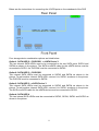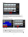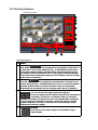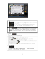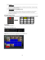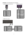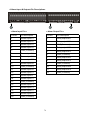
1
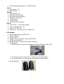
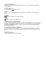
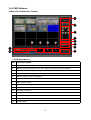
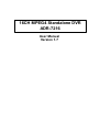
16CH MPEG4 Standalone DVR
ADR-7216
User Manual
Version 1.7
Statement
The information of the product in this manual is subject to change without prior notice and
does not represent a commitment on the part of vendor, who assumes no liability or
responsibility for any errors that may appear in this manual.
This manual contains materials protected under International Copyright Laws. All rights
reserved. No part of this manual may be reproduced, transmitted or transcribed without the
written consent of the manufacturer.
1
Table of Contents
Section1 Introduction...........................................................................................................................3
1.1 Overview....................................................................................................................................3
1.2 Features......................................................................................................................................3
1.3 Specifications.............................................................................................................................3
1.4 Package......................................................................................................................................4
Section2 Appearance............................................................................................................................5
2.1 Front Panel.................................................................................................................................5
2.2 Rear Panel..................................................................................................................................8
Section3 Installation...........................................................................................................................10
3.1 Before Installation....................................................................................................................10
3.2 HDD Installation......................................................................................................................12
3.3 DVD-RW Installation..............................................................................................................13
Section4 Menu....................................................................................................................................14
4.1 Menu Display...........................................................................................................................14
4.2 Menu Tree................................................................................................................................15
4.3 SYSTEM..................................................................................................................................17
4.4 DISPLAY.................................................................................................................................25
4.5 RECORD.................................................................................................................................27
4.6 EVENT....................................................................................................................................29
4.7 SCHEDULE.............................................................................................................................31
4.8 NETWORK.............................................................................................................................33
4.9 COPY(BACKUP) ...................................................................................................................36
4.10 HARD DISK..........................................................................................................................37
4.11 CAMERA..............................................................................................................................39
Section5 Searching for Playback .......................................................................................................41
Section6 Live Display .......................................................................................................................42
Section7 Backup using USB memory driver, CD or DVD ...............................................................43
Section8 PTZ Control ........................................................................................................................45
Section9 F/W Upgrade.......................................................................................................................46
Section10 Client Software..................................................................................................................48
10.1 Client Software (NetViewer, File Player, CMS) Installation ................................................48
10.2 NetViewer Software ..............................................................................................................50
10.3 File Play Software..................................................................................................................66
10.4 CMS Software........................................................................................................................70
APPENDIX 1. Pin Description of connectors ...................................................................................78
2
Section1 Introduction
1.1 Overview
Designed for globally increasing surveillance requirements, ADR-7216 is a high
performance standalone Digital Video Recorder. It takes the advanced MPEG4
compression format to solve the storage problem of huge amount of video, and the friendly
UI design also enables users even unfamiliar with computer operations can easily control
this DVR. Specially, Advanced network functions are added in ADR-7216 to fulfill the
growing IP applications. This product also supports Pentaplex, which enables Live,
Record, Playback, Backup and Network to be performed simultaneously. This high-quality
DVR is absolutely the best choice for your security surveillance.
1.2 Features
●
●
●
●
●
●
●
●
●
MPEG4 compression format, D1 resolution
16ch all real-time recording & display
eSATA interface for external storage expansion
Multiple recording modes
User-friendly GUI & Multi-language OSD
USB Interface for firmware update & data archiving
Mouse control
Pentaplex: Live, Record, Playback, Backup & Network
Advanced Network function
1.3 Specifications
Video
● Video Input:16ch (BNC)
● Loop Out:16ch (BNC)
● Main Monitor Out:BNC*2, S video*1 & VGA*1
● Call Monitor Out:BNC*1
● Video Compression Format:MPEG4
● Display Mode:Full, 4, 9 & 16
Audio
● Audio Input:16
● Audio Output:2
Record
● Resolution (Max.):D1:720x480 (NTSC), D1:720x576 (PAL)
● FPS:up to 480fps at CIF (NTSC), up to 400fps at CIF (PAL)
(Adjustable: 240fps at Half-D1 (NTSC), 200fps at Half-D1 (PAL)
120fps at D1 (NTSC), 100fps at D1 (PAL) )
● Mode:Manual, Schedule, Alarm & Motion
Storage
● HDDs:Support Internal SATA HDD*2/ 3 (3.5")
● Support built-in DVD-RW
3
External Storage Expansion:eSATA Interface
Alarm
● Alarm Input:16
● Alarm Output:4
Network
● Live video access
● Recorded video access
● Recorded video download
● Remote configuration
● CMS support
● e-map support
● Remote event notification
Others
● PTZ Control:15 protocols support
● Video loss detection:Yes
● Power:DC 12V / 7A
● Dimension:430 (W) x 88 (H) x 340(D) mm
●
1.4 Package
●
●
●
●
●
●
●
Digital Video Recorder ADR-7216*1
Power Adapter*1
Power Cord*1
Support CD (including PC_SW, User Manual)
IR Remote Controller*1
Batteries (AAA)*2 (used for IR remote controller)
Screw Bag*3
1. Black screws are used for screwing the two Mount Brackets to the DVR.
2. the 8 silver screws in one pack are used for screwing DVD-RW
3. the 24 silver screws in one pack are provided for screwing HDDs.
●
Mount Bracket*2
4
Section2 Appearance
2.1 Front Panel
1. DVD-RW
This can be used for backup video.
2. Jog and Shuttle
Jog and shuttle enable user to operate DVR easier in handling such as fast forward, fast
reverse playback and one frame movement in still picture.
3. LED Indicators
1) POWER
This red LED turns “ON” when Power is “ON”.
2) NET
This green LED will turn “ON”, while data through network is transmitting.
3) COPY
This green LED will turn “ON” during data COPY through DVD-RW or USB Memory driver.
4) REC
This red LED will turn “ON” during recording.
5) LOCK
This yellow LED will turn “ON” while LOCK button is working.
6) Remote Controller receiver
Remote controller sensor input window.
5
4. Channel Selection buttons
Channel selection button from CH1 to CH16 can be used to display given channel on
monitor.
5. Function buttons
1) FUNC
This button is reserved for future use.
2) LOCK
In order for only authorized person to operate buttons in front panel, this LOCK button can
be utilized. If this button is pressed, all of buttons in front panel are not operated at the
same time yellow LOCK LED ON. To release button locking, password will be just
requested after pressing LOCK button. If correct password is input, button LOCK will be
released
3) PTZ (Pan, Tilt and Zooming)
The camera(s) with panning, tilting and zooming function would be connected with one
and some of video inputs of rear panel of DVR. In order to control PTZ function of the
camera, PTZ button is pressed first. And then direction button for panning and tilt can be
pressed, ▶▶ and ◀◀ for zooming in/ out can be used in PTZ mode.
4) COPY button (Backup)
This COPY button can be used to retrieve some of recorded files into backup media like
USB memory drive or CD/ DVD after searching recorded files.
NOTE: the media for backup (USB memory driver or CD/ DVD) can be changed in the
COPY sub-menu.
5) (Sequential Display button)
If this button is pressed under given video display mode, each video display mode is
switched sequentially. For example, if this button is pressed in QUAD mode, QUAD
picture is switched sequentially from CH1-4, CH5-8 to CH13-16.
6) (Display mode selection button) Full, Quad, 9-split, 16-split
Whenever these button is pressed, display mode can be changed from QUAD, 9CH to
16CH display mode.
7) REC/ STOP button
REC button is pressed to start recording and to stop recording again. This is toggle
button. When DVR is under recording mode, this icon
will be appeared on each CH.
8) Search button
This can be used to find out proper recorded file for playback or copy (backup). Searching
list can be displayed by pressing this button.
9) REW
This button can be used for high speed backward playback. It support 2 to 16 times
playback speed.
6
10) PLAY/ PAUSE button
If this button is pressed, playback picture will be frozen. If it is pressed again, playback
will be restarted.
11) STOP button
To stop playback, STOP button is used.
12) FF
Press FF button to do high speed forward playback. It support 2 to 16 times playback
speed.
13) MENU
MENU button is pressed to enter menu system.
14) ESC
ESC button is used to return upper menu.
6. Direction button and Enter Button
Direction buttons are used to move LEFT, RIGHT, UP and DOWN in menu. They also can
be used to input password. ENTER button is used to save parameter, to select parameter
in the menu. And also in playback it is used to select one of listed file for playback after
searching recorded files .
7. Power Button (Power On/ Off button)
This Power button can be pressed to turn off DVR power. When this button is pressed,
password is requested. When right password is input to DVR, DVR power will be turned
off.
8. USB 2.0 connector
Used for data archiving and F/W upgrade.
7
2.2 Rear Panel
1. FAN
2. 16CH Video Inputs
16 channel composite video inputs with BNC connectors . Since this DVR automatically
detects video format (NTSC or PAL) as soon as power is ON, NTSC or PAL video sources
can be connected in DVR. But NTSC and PAL video sources for 16CH video inputs can
not be mixed. If they are mixed, DVR can’ not be operated properly.
3. 16CH Loop through outputs 16 channel composite video outputs with BNC
connectors. If the connection of loop-through video outputs into another video
equipments is requested, 16CH Loop-through outputs can be utilized for it.
4/5. 16CH Audio input (RCA) and 2CH Audio Output (RCA)
Unbalanced audio signal input and output with RCA jack. Connect the audio source to
audio input, audio output to your amplifier because the DVR don’t amplify audio output.
A speaker with an amplifier will be needed for audio playback. The audio input can be
from an amplified source or directly from a microphone.
6. 3CH composite Video Output and 1 S-Video Output
Two video output (MON1 and MON2) and one S-Video are used to monitor live,
playback pictures. They are same video output. The other is used to monitor SPOT
output which displays all of connected video channels sequentially.
7. Power Input (from Adapter)
Connect the adapter to the DVR for DC power supply. (DC 12V / 7A).
8
8. VGA Output
VGA output can be connected to LCD monitor or CRT monitor with progressive scan
directly which can receive analog R, G, B and synchronization signals.
9. RS232C (It can be utilized for future option.)
10/11. Alarm input and relay output
16 alarm inputs and 4 relay output with NO, NC
To make secure connections on the Alarm Connector Strip, press and hold the button
and insert the wire in the hole below of connector pin. After releasing the pin, pull
gently on the wire to make certain it is connected. To disconnect a wire, press and
hold the connector pin above the wire and pull out the wire.
1) 16 Alarm Inputs: 1,2,3,4,…, 16,G(Ground)
You can use external devices to signal the DVR responding to events. Mechanical or
electrical switches can be wired to the Alarm Inputs and GND (Ground) connectors.
The threshold voltage is 4.3V and should be stable at least 0.5 seconds to be detected.
2) G (Ground), COM (common):
Connect the ground side of the Alarm input to G (Ground). Connect the ground side of
relay output to COM connector.
3) 4 Relay output:
4 relay output with NO or NC can be sent to external device. You can select NO or NC,
according to characteristic of mechanical or electrical switch.
12. RS485
PTZ cameras can be controlled remotely through this RS485 port. Connect RX+, RX- of
the control system to the TX+, TX- (respectively) of the DVR.
13. Ethernet Port
Connect a Cat5 cable with an RJ-45 jack to the DVR connector. Remote PC viewer
software via network enable you to access live viewing, searching and other available
functions.
14. eSATA Port for External Storage Expansion
eSATA device like RAID system is supported for storage expansion, you can connect it to
eSATA port via eSATA cable. Make sure that you have turned on the eSATA external
storage device before DVR power on.
9
Section3 Installation
3.1 Before Installation
The DVR picture is shown below. First, open the upper casing by using a screwdriver to
loosen the screws. The screws are located at the top (1), on the sides (4) and at the back
(2) of DVR as indicated by the red circles. Remove the screws and keep them in a safe
place for latter use.
Once the upper casing is removed, the internal layout can be seen. The DVD-RW rack is
on the left side while the HDD racks are on the right side.
10
Below are the instructions for connecting the 4 SATA ports on the mainboard of the DVR
Four storage device combination options are listed below.
Option1. SATA HDD*2 + DVD-RW*1 + eSATA Device*1
The two internal SATA HDDs need to be connected to the two SATA ports, SATA3 and
SATA4 as shown in the picture. The SATA-to-eSATA cable for the eSATA device must be
connected to SATA1, the DVD-RW must be connected to SATA2.
Option2. SATA HDD*3 + DVD-RW*1
Two internal SATA HDDs must be connected to SATA3 and SATA4 as shown in the
picture. To add another internal SATA HDD, connect it to SATA1 as shown in the picture.
The DVD-RW must be connected to SATA2.
Option3. SATA HDD*3 + eSATA Device*1
Two internal SATA HDDs must be connected to SATA3 and SATA4 as shown in the
picture. To add another internal SATA HDD, connect it to SATA1 as shown in the picture.
The SATA-to-eSATA cable for the eSATA device must be connected to SATA2.
Option4. SATA HDD*4
The two internal SATA HDDs must be connected to SATA3, SATA4, SATA1 and SATA2 as
shown in the picture.
11
3.2 HDD Installation
Loosen the screws holding the two HDD racks in DVR case to remove the HDD rack, then
install the HDD in place as shown below using the screws.
Once the HDDs are installed into the HDD racks, place the racks back, align them with the
holes on the chassis and tighten the screws.
Finally, connect the SATA cable and SATA power cable to the back of the HDDs Installed.
12
3.3 DVD-RW Installation
Loosen the four screws holding the DVD-RW rack in place as shown below and remove
the DVD-RW rack then.
Remove the two screws on the DVD-RW rack and split it as the two part shown as below.
Position the two mounting plates on either side of the DVD-RW then tighten them with
screws. Now place the assembly inside the DVR chassis, align the mounting plates with
the mounting holes on the chassis and screw into place.
Finally, connect the SATA cable and SATA power cable to the back of the DVD-RW.
DVD-RW Installation is now complete.
13
Section4 Menu
4.1 Menu Display
Menu Icons
No.
ICON
NAME
No.
ICON
NAME
1
SYSTEM
6
NETWORK
2
DISPLAY
7
COPY
3
RECORD ING
8
HDD
4
EVENT
9
CAMERA
5
SCHEDULE
14
4.2 Menu Tree
LANGUAGE
VIDEO FORMAT
SEQ DWELL
PASSWORD
STOP KEY
SPOT DWELL
ADMIN LOCK
REC SETTING
TIME/DATE OSD
SUB-USER
CAM NO OSD
REMOTE CONT ID
VIDEO LOSS OSD
TIME FORMAT
POP-UP DISPLAY
DATE FORMAT
ADJUST CH
DATE/ TIME SET
PRIVATE
VERSION NO.
1
SYSTEM
CH QUALITY SET
FACTORY RESET
2
DISPLAY
QUALITY RESET
UPGRADE
3
RECORD
4
EVENT
5
SCHEDULE
6
7
NETWORK
COPY
SETUP1
SCHEDULE
CONNECT
IP ADDRESS
ON/ OFF
WEEKLY
SETUP2
MOTION AREA CH
MOTION AREA
DAILY
8
HDD
SUBNET
9
CAMERA
GATEWAY
DNS
PORT
TIME ZONE
NTP TIME SYNC
DEVICE
OVERWRITE
BACKUP LOG
CAMERA NO
FORMAT HDD
CD/DVD FORMAT
CAMERA ID
INFO
BACKUP INFO
PTZ TYPE
PTZ ID
BAUD RATE
15
<Enter the Menu >
For the first time using your DVR, you will want to establish the initial settings. This
includes setting items such as time and date, password, display, record mode, network
and so on.
In order to program Main Menu, first press MENU button of front panel in DVR.
If ADMIN LOCK is set as YES (factory default is YES), below figure will be appeared.
Then input password number using 1, 2, 3, … , 9 Channel Buttons (Factory default
password is 11111111), and press ENTER button. MAIN MENU will be appeared.
NOTE:
To access the DVR Main Menu, press MENU. To escape MENU, ESC button can be used.
Buttons for movement in Menu are ▲ or ▼. Button for selection is ENTER, Button for
increasing or decreasing setting value is ◀ or ▶. Press ESC to return to the previous
MENU after setting and to save the values of setup.
16
4.3 SYSTEM
To access SYSTEM SETUP, press ENTER button after moving highlight icon to SYSTEM
in MAIN MENU. Below menu will be appeared on monitor.
1) LANGUAGE
The OSD language which can be displayed in Menu can be selected.
Whenever left or right button is pressed , supported language can be selected.
For language selection by graphical user interface, ENTER button can be pressed.
Below GUI for language selection will be appeared.
By using up or down button, supported
language can be selected.
17
2) VIDEO FORMAT: NTSC/ PAL
Video format is automatically detected after power ON. The detected video information
will be displayed on VIDEO FORMAT. User don’t need to change video format.
NOTE: It is recommended that power is “ON” after camera(s) connection for video
format recognition.
3) PASSWORD:
Move Highlight icon to PASSWORD in the SYSTEM Menu using DOWN or UP button. And
press ENTER button to change password. Then below “old password” window will be
appeared. NOTE: Factory Default is “11111111”.
After inputting old password, input new password using from 0 to 9 button. And It needs to
input new password again to confirm new password.
18
5) SUB-USERS :
NOTE: This function is available only in ADMIN LOCK with “YES”.
Sub-User function can provide multiple user with the differentiated DVR accessing from
ADMIN, user1 to user4. The function(s) which each user can use is limited by ADMIN.
In order to assign different functions for each user, SUB USERS of SYSTEM SETUP
MENU can be selected.
The detail function selection for each SUB USER can be done like below
There are SETUP (for MENU configuration setup), SEARCH (for PB and COPY), PTZ
(for PTZ camera control), NETWORK, PRIVATE which can hide picture from monitor.
After doing setting, ESC button enable to return upper MENU.
NOTE: In the detail function selection for each SUB USER, SETUP item should be
“ON” for each user password changing.
19
<The procedure for SUB-USER password modification>
The initial password for SUB-USER is same as ADMIN’s password, “11111111”.
The modification for each sub-user can be followed by specific user selection in MENU.
NOTE: The SETUP (for MENU configuration setup) for the user should be “On” by
ADMIN in advance.
Click Password.
Initial password
is “11111111”.
Input new Password
(8 digit).
Confirm new Password
20
If SETUP (for MENU configuration setup) for the user isn’t set as “On” by ADMIN in
advance, below error message, “ACCESS DENIED!” will be appeared on monitor.
If password is not same, same window for password will be kept.
6) Remote ID :
DVR can set remote ID from 01 t0 16 by manual or mouse at first. If it set as “Off”, DVR
receives all the remote controller signal. It means that DVR don’t use remote ID. Factory
initial setting is “Off”.
Remote ID function:
This remote controller ID function (REMOTE ID function) can be useful in when only
one DVR among multiple DVR can be controlled by one remote controller. It is
described as infra-red signal locking function coming from remote controller in the DVR
which don’t have same remote ID
21
How to use Remote ID:
Remote ID in REMOTE ID of SYSTEM MENU of DVR can be set by manual or mouse.
Each DVR can have REMOTE ID from 01to 16. Factory initial setting is “Off”. It means that
DVR don’t use Remote ID.
If any number of Remote ID is pressed by FUNC + No. button from 1 to 16, other DVR
which don’t have same Remote ID will lock the signal from remote controller with
displaying the “remote Lock Icon” on the left top side of monitor.
NOTE: Remote Controller Lock function can be set only in live picture mode.
7) TIME FORMAT: 24/ 12 HOURS
Move Highlight icon to TIME FORMAT in the SYSTEM Menu using DOWN or UP button
and press the LEFT or RIGHT button to select 24 HOURS or 12 HOURS (AM/PM).
Whenever Time Format is changed, clock information on monitor and file information in
search list will be changed together.
8) DATE FORMAT: MM-DD-YY/ DD-MM-YY/ YY-MM-DD
Move Highlight icon to DATE FORMAT in the SYSTEM Menu using DOWN or UP
button. Date format can be changed using LEFT or RIGHT button.
22
9) DATE/ TIME SET :
Move Highlight icon to DATE/TIME SET in the SYSTEM Menu using DOWN or UP
button. And then press ENTER to set the time. Below GUI will be appeared.
NOTE:
If you set a date and time that is older than
some of your recorded images, it is not
easy to manage recorded files. Before
starting your DVR, DATE/ TIME should be
setting properly.
It can be moved to DATE or TIME using DOWN or UP button. The movement to year,
month, day is done by LEFT or RIGHT button. The year change can be done by DOWN
or UP button. Month, day can be adjusted as same way. After setting DATE/ TIME,
YES is used in order to save setting value and to return upper menu.
11) FACTORY RESET: Return to factory default setting value.
If ENTER is pressed for factory reset, below GUI will be appeared. If ENTER is pressed
again, all the setting value will be returned into factory initial value with “Default Complete”
message like below GUI.
23
12) UPGRADE
Firmware can be upgraded through USB memory driver. For more detail information,
Please see “Section9 F/W Upgrade”
NOTE:
When all of menu setting are finished, escape menu mode, below figure “SAVE?”
which ask to save all the setting will be appeared. If all the menu setting is needed to save,
“Check Mark” can be pressed. If not, “X” can be selected.
24
4.4 DISPLAY
To access DISPLAY SETUP, press ENTER button after moving highlight icon to DISPLAY
in MAIN MENU. DISPLAY SETUP will appear on monitor.
1) SEQ DEWLL TIME: NONE/ 1 to 60 seconds.
SEQ DWELL TIME can be adjusted using LEFT or RIGHT button. Or after pressing
ENTER button, SEQ DWELL TIME from none, 1 seconds to 60 seconds which decide a
period of channel by channel can be selected by UP or DOWN button. And then ENTER
button is used for confirming setting value.
2) SPOT DWELL: 1 to 60 seconds.
SPOT DWELL TIME can be changed using LEFT or RIGHT button. Or after pressing
ENTER button, SEQ DWELL TIME from none, 1 seconds to 60 seconds which
decide a period of channel by channel can be selected by UP or DOWN button. And then
ENTER button is used for confirming setting value. All of video channels connected with
video inputs of DVR can be sequentially switched for SPOT monitoring output.
3) TIME/DATE OSD: ON/ OFF
When it is set as OFF, characters which indicates time/ date will be disappeared on
monitor. But time and date information still are added into recording files.
TIME/DATE OSD ON/ OFF can be changed using LEFT or RIGHT button.
25
4) CAM NO OSD: ON/ OFF
When it is set as OFF, characters which indicates camera number will be disappeared on
monitor. CAM NO OSD ON/ OFF can be changed using LEFT or RIGHT button.
5) VIDEO LOSS OSD: ON/ OFF
VIDEO LOSS OSD ON/ OFF can be changed using LEFT or RIGHT button. When it is set
as OFF, black pictures will be displayed when video loss. When it is set as ON, “VIDEO
LOSS” character with white color will be displayed in blue screen.
6) POP-UP DISPLAY: ON/ OFF
POP-UP DISPLAY ON/ OFF can be changed using LEFT or RIGHT button. When it is
set as OFF, pop-up image of camera(s) which motion detection or alarm triggering is
occurred will not be displayed. When it is set as ON, the channel (s) which motion is
(are) detected or external alarm is (are) triggered will be POP-UP in monitor during
maximum 30 seconds. In case that motion detection or alarm event is occurred more
than two channels, POP-UP picture will be appeared in monitor turn by turn during 3
seconds for each channels. Total period of POP-UP display is 30 seconds.
7) ADJUST CH: CH1, CH2, CH3, CH4, … , CH16
The camera channel needed to adjust brightness, contrast, Hue & Saturation can be
selected.
8) PRIVATE
The video channel which don’t want to display on monitor can be selected by LEFT or
RIGHT button. Selected channel isn’t displayed on monitor while live or playback
display. The private channel is displayed black screen.
9) CH QUALITY SET
Quality control including brightness, contrast , hue and saturation can be adjusted.
BRIGHTNESS/ CONTRAST: 1 to 99 %
BRIGHTNESS can be changed using LEFT or RIGHT button. CONTRAST can be
changed using UP or DOWN button.
HUE/ SATURATION: 1 to 99 %
HUE can be changed using LEFT or RIGHT button. SATURATION can be changed using
UP or DOWN button.
NOTE: Minimum value is 1 (very dark), maximum value is 99 (very bright).
In order to move from BRIGHTNESS/ CONTRAST to HUE/ SATURATION adjust or
vice versa, ENTER button can be pressed. In the full screen, picture quality adjust
channel can be moved easily by pressing
or
button.
10) QUALITY RESET
Quality control including brightness, contrast, hue and saturation can be reset by
factory initial value by this QUALITY RESET.
26
4.5 RECORD
To access RECORDING SETUP, press ENTER button after moving highlight icon to
RECORD in MAIN MENU. RECORDING SETUP will appear on monitor.
1) STOP KEY: DISABLE/ ENABLE
In case of manual recording, manual recording is started and stopped by the REC/
STOP button in the front panel of DVR. This REC/ STOP button DISABLE can protect
the “recording stop” by unauthorized person intentionally. The “STOP KEY DISABLE/
ENABLE” can be changed using LEFT or RIGHT button. Or after pressing ENTER button,
“STOP KEY DISABLE/ ENABLE” can be selected by UP or DOWN button. And then
ENTER button is used for confirming setting value.
This DVR has the performance which can record real-time 16ch video and 16 audio at the
same time. Recording enable/ disable, resolution, recording quality, frame rate and audio
ON/ OFF, pre-recording ON/ OFF and so on related to individual video channel and audio
channel can be adjusted separately.
27
2) REC SETTING
- Resolution: FULL (4 CIF, D1), HALF(2 CIF, Half D1), NORMAL (CIF)
- Quality: VERY LOW, LOW, STANDARD, HIGH, VERY HIGH
- FPS: 30 to 1 FPS.(NTSC)/ 25 to 1 FPS (PAL)
- REC: MANUAL, Schedule, EVENT, OFF
- Audio: ON or OFF
- Lock: ON or OFF (If “Lock” is ON, this recorded file isn’t be deleted, even though
HDD over-writing is done. )
Resolution
Quality ( 5 Level)
FPS: 1 to 30 FPS
REC: MANUAL/ …/ Off
Audio: On/ Off
Lock: On/ Off
Exit current GUI
NOTE: FPS can automatically changed according to video resolution.
28
4.6 EVENT
4.
If EVENT is selected by ENTER button, below “EVENT SETUP” figure will be appeared.
All the parameters related to EVENT Recording from CH1 to CH16 which include
QUALITY, FRAME RATE, DURATION can be selected separately.
EVENT Setup1 Selection
EVENT Setup2 Selection
Motion Area CH selection
Motion Area Selection
1) Event Setup1 parameter Setting
Recording Quality (5 step):
Very Low, Standard, Very High
FPS: 1 to 30 FPS
EVT (Event):
ALARM or MOTION
Pre (Pre-recording): On/ Off
Duration: recording time
Selection. (30 sec to 60min.)
Exit this menu.
29
2) Event Setup2 parameter Setting
Sensitivity (5 step):
Very Low, Normal, Very High
Sensor: N.O or N.C
Input: CH1 to CH16
Output:
Trigger Output Selection
Any output OFF, CH1 to CH4
can be selected.
Buzzer: On/ Off
Exit this menu.
3) MOTION AREA CH and 4) MOTION AREA
Motion Area CH selection
Motion Area selection
The MOVE mode which can just
move motion area by LEFT or
RIGHT or UP or DOWN button.
Whenever ENTER button is pressed, marking within above red circle will changed from
“DIRECTION” mark to “+” and “-” mark. In the “Direction” mark, motion area can be
moved with direction button like LEFT or RIGHT or UP or DOWN button. In the “+”
mark, motion area can be enabled by direction button. In the “-” mark, motion area
can be disabled by direction button.
Motion channel can be changed by
or
button from CH1 to CH16.
30
4.7 SCHEDULE
SCHEDULE in the main menu can be selected by movement button such as LEFT, RIGHT
or UP, DOWN button. If SCHEDULE is selected by ENTER button, below “Schedule
Select” will be appeared.
1) “OFF” or “Weekly SET” or “ Daily SET” can be configured in Schedule Select. It can be
selected by LEFT or RIGHT button.
“OFF” means that there is no Schedule SETUP. It means that there is no recording
except manual recording, event recording.
31
2) Weekly SET
If “Weekly SET” is selected, below figure will be appeared. It is possible to configure
ALARM, MOTION and MANUAL together in Weekly SET figure. Each mode from
ALARM, MOTION to MANUAL can be changed by ENTER button. In Weekly SETUP
Figure, movement button consists of LEFT, RIGHT or UP, DOWN button. Schedule Setting
can be done by REW (◀◀) or FF (▶▶) button. To return upper menu, ESC button can be
used.
3) Daily SET
If “Daily SET” is selected, below figure will be appeared. It is also possible to configure
ALARM, MOTION and MANUAL together in Daily SET figure as Weekly SETUP. Each
mode from ALARM, MOTION to MANUAL can be changed by ENTER button. In Daily
SETUP Figure, movement button consists of LEFT, RIGHT or UP, DOWN button. Schedule
Setting can be done by REW (◀◀) or FF (▶▶) button. To return upper menu, ESC button
can be used.
When recording schedule of Weekly SET is finished,
or
mark in date
Box will be added.
This mark indicates there is MANUAL setting in specific day.
This mark indicates there is EVENT setting in specific day.
32
4.8 NETWORK
If NETWORK is selected by ENTER button, below “NETWORK SETUP” figure will be
appeared.
1) CONNECT: STATIC or DHCP
STATIC IP or DHCP of CONNECT can be selected by LEFT or RIGHT button. Or after
pressing ENTER button, STATIC or DHCP can be selected by UP or DOWN button. And
then ENTER button is used for confirming setting value.
2) IP ADDRESS, 3) SUBNET MASK, 4) GATEWAY, 5) DNS:
If DHCP is selected, IP ADDRESS/ SUBNET/ GATEWAY/ DNS will be automatically
assigned. But If STATIC is selected, manual input for IP ADDRESS/ SUBNET/ GATEWAY/
DNS will be needed.
33
For assigning IP ADDRESS, SUBNET, GATEWAY and DNS in STATIC IP mode, ENTER
button can be pressed on the column of IP address, SUBNET, GATEWAY and DNS. Then
below NETWORK SETUP figure will be appeared.
The 4 number group with 3 digit expressing IP ADDRESS, SUBNET, GATEWAY and DNS
can be increased by UP button or decreased by DOWN button. The position movement
between 4 numbers can be done by LEFT or RIGHT button. The position movement from
IP address, SUBNET to DNS can be done by UP or DOWN button. In order to save the
assigned number of IP address and so on, “Yes” should be selected by ENTER button in
“check” box.
6) PORT: Port number for TCP/IP connection in DVR
Net-Viewer software should have same port Number to access remote DVR through
network. Default Port No. is 10000. If Port is set as 10000, port number of from 10000 to
10020 is used in DVR. Therefore, If DVR is used in network environment with firewall, port
number of from 10000 to 10020 should be opened for DVR remote access. If IP sharing
machine or router is used with DVR, “port forwarding” should be done.
7) TIME ZONE: City Name
Time information can be synchronized with time server.
NOTE: Time zone setting can be useful for Summer Time setting.
34
8) NTP TIME SYNC: OFF/ON
DVR can synchronize “standard time” with Time Server using Network Time Protocol.
NOTE: If DNS server is not set properly in fixed IP address, this function will not be
operated.
9) DDNS STATUS: Dynamic DNS status display (This DDNS status is just readable.)
It is recommended not to use this DDNS service for fixed IP or IP sharing machine.
NONE- It indicate that DDNS is not used.
ERR- DDNS IP update failure
OK - Normal operation
35
4.9 COPY(BACKUP)
BACKUP in the main menu can be selected by movement button such as LEFT, RIGHT or
UP, DOWN button. If BACKUP is selected by ENTER button, below “BACKUP” figure will
be appeared.
1) DEVICE: USB Storage or CD/DVD
NOTE: the media type (USB Storage or CD/DVD) used for video backup also should be
selected here.
2) BACKUP LOG: NONE or ENTER
All of log information including DVR power ON/ OFF, recording time, event time and so on
can be BACKUP through USB Memory driver. After BACKUP log file, you can see
BACKUP log information using Word-Pad of PC. ENTER button is used to start the
BACKUP of LOG data. If there is no BACKUP media, “No BACKUP media !” message will
be appeared.
3) CD/DVD RW FORMAT / USB FORMAT
It is used for CD/DVD RW / USB FORMAT.
When recorded files in DVR is copied or backup into CD R/W or DVD R/W, it is
recommended to format CD R/W or DVD R/W using this CD/ DVD RW FORMT function
before backup.
4) BACKUP INFO:
First, connect USB memory drive in USB port of DVR front panel. And then enter menu
mode. You can see the information of USB Memory Drive inserted in DVR like USB
memory drive manufacturer, total memory size, available memory size.
36
4.10 HARD DISK
HDD DISK in the main menu can be selected by movement button such as LEFT, RIGHT
or UP , DOWN button. If HDD is selected by ENTER button, below “HARD DISK” figure
will be appeared.
1) OVERWRITE:
HDD OVERWRITE can be used for repetitive recording in to same HDD space. First
recorded area in HDD can be replaced with new recording data. OVERWRITE can be
selected by LEFT or RIGHT button. Or after pressing ENTER button, OFF or ON can be
selected by UP or DOWN button. And then ENTER button is used for confirming setting
value.
37
2) FORMAT HDD:
This support quick HDD format function. In order to format HDD in FORMAT HDD, after
pressing ENTER button, “YES” or “NO” can be selected by LEFT or RIGHT button for
HDD format
3) INFO: It shows total HDD capacity mounted in DVR.
38
4.11 CAMERA
CAMERA in the main menu can be selected by movement button such as LEFT, RIGHT
or UP, DOWN button. If CAMERA is selected by ENTER button, below “CAMERA
SETTING” figure will be appeared. The movement from CAMERA NO to PTZ type in
CAMERA SETTING can be done by UP or DOWN button.
1) CAMERA NO: CH01 – CH16
Camera ID and PTZ protocol for 16 cameras can be separately adjusted in CAMERA
SETTING menu. After selecting CAMERA NO., CAMERA ID and PTZ can be adjusted.
CAMERA NO can be selected by LEFT or RIGHT button.
2) CAMERA ID
After selecting CAMERA NO first for CAMERA ID changing, CAMERA ID can be changed
by OSD keyboard of below figure. When ENTER button is pressed, below figure will be
appeared.
Movement in OSD keyboard can be done by LEFT, RIGHT or UP , DOWN button. If
ENTER button is pressed under “SPACE” selection, under-bar character will be
generated. If ENTER button is pressed under “BACK” selection, one character which is
added last will be eliminated. If ENTER button is pressed under “MODE” selection,
alphanumeric small character and large character will be exchanged. If ENTER button is
pressed on alphanumeric character, that character will be added in CAMERA ID. In order
to save modified CAMERA ID, “OK” should be selected before leaving OSD keyboard.
39
3) PTZ TYPE (Pan, Tilt and zooming protocol selection ): Panasonic/ Pelco-D/ PelcoP/
Techwin/ Niko/ DRX502A_DSC230s /KRE_301_302/ GC_755_NP/ TOA_CC554/
AS716LS and so on.
The high end camera(s) with panning, tilting and zooming function would be connected
with some of video inputs. The camera(s) has(have) its own control protocol needed to
control panning, tilting and zooming, according to PTZ camera manufacturer.
NOTE: PTZ stands for pan, tilt and zooming.
4) PTZ ID: ID No. from 00 to 19.
PTZ camera ID can be selected for different channel connection.
5) BAUD RATE: Baud rate from 2400 to 19200 BPS can be selected according to PTZ
camera.
40
Section5 Searching for Playback
If search button is pressed for playback, all the search list with calendar style as below
figure will be appeared. The search category such as ALL/ SCHEDULE/ MOTION/
ALARM/ MANUAL and TIME to find out recorded file much faster which want to play can
be selected by DOWN or UP button.
After moving to Date using LEFT or RIGHT button, searching day in calendar can be
changed by DOWN or UP button. After pressing ENTER button, The specific day can be
selected.
After pressing ENTER button,
First, select specific time of
24 hours using LEFT or
RIGHT button. Then press
ENTER button for playback.
While your DVR is in playback mode, the display channel which want to watch could be
selected by display selection button or single channel button. Fast forward or fast
backward playback can be done by FF (▶▶) and REW (◀◀) button.
In order to freeze picture in playback, PLAY/PAUSE button is used. The movement of
single field in still picture mode can be fulfilled by LEFT or RIGHT button.
And Jog and shuttle dial also enable user to use FF, REW as well as single frame
movement easily. Your DVR supports x2,x4,x8,x16 playback for Fast Forward, x2,x4,x8,
x16 play back for Fast Backward.
For display channel selection,
can be pressed.
Whenever these button is pressed, display mode can be changed from QUAD, 9CH to
16CH display mode. Single channel display can be displayed by No 1 to No 16 button .
Playback audio selection for speaker output:
One of audio channels which want to output
through speaker can be selected by “MENU”
button just after pressing “F1” button.
Audio channel can be easily selected by
movement buttons in the figure.
41
Section6 Live Display
There are some of live display modes such as single (as full), QUAD, 9 picture, 16 picture.
A) Full Picture
C) 9 picture Display
B) QUAD picture
D) 16 picture Display
Live audio selection for speaker output:
One of audio channels which want to output
through speaker can be selected by “MENU”
button just after pressing “F1” button.
Audio channel can be easily selected by
movement buttons in the figure.
Status Symbols description
Function
Symbol
Details
Recording
Manual, Motion, Alarm
Key Lock
It is displayed in “left top” on monitor.
Network
It is displayed in “left top” on monitor.
PTZ
It is displayed in “left top” on monitor.
BACKUP
CD or DVD. It is displayed in “left top” on monitor.
USB. It is displayed in “left top” on monitor.
REMOTE ID
Multiple DVR installed same space can be
controlled by one Remote Controller using Remote
Cont ID. It is displayed in “left top” on monitor.
42
Section7 Backup using USB memory driver, CD or DVD
1) In order to search the file which is needed to copy in USB memory or CD or DVR,
search button of front panel of DVR can be pressed. Below GUI will be appeared.
2) When Option “ALL” is highlighted, you can select one of recording type including ALL,
manual, alarm, motion and schedule recording using UP or DOWN button. According to
selection of recording type, recorded files will be listed in below calendar. After moving to
Date using LEFT or RIGHT button, searching day in calendar can be changed by DOWN
or UP button. After pressing ENTER button, The specific day can be selected.
After selecting the file which want to copy using direction button including LEFT or RIGHT,
and pressing ENTER button, below figure will be appeared.
3) COPY (BACKUP) button of front panel of DVR can be pressed, and then COPY
(BACKUP) time can be decided.
43
4) If COPY(BACKUP) time is decided by ENTER button, Below GUI will be appeared. The
channel(s) which want to copy can be selected here. According to channel selection,
information about total file size to be copied will be shown.
5) It will start to copy the selected file, as soon as check box is pressed.
44
Section8 PTZ Control
a) Select the camera (which PTZ camera is connected) to control PTZ using Channel
Selection button from CH1 to CH16 in front panel of DVR.
b) Press PTZ button to select PTZ mode. PTZ MODE OSD
upper right corner of monitor.
will be displayed on
c) Use UP, DOWN button for up and down movement of PTZ camera, LEFT, RIGHT for
left and right movement and
,
buttons for zoom IN and OUT.
d) To escape PTZ control mode, press ENTER button or any button. Then the PTZ MODE
OSD on upper right corner of monitor will be disappeared.
NOTE:
Before using PTZ control mode, please check that PTZ protocol in PTZ TYPE of
CAMERA SETTING is correctly selected.
45
Section9 F/W Upgrade
1) Copy upgrade firmware file, “dvr535352xx.tgz” into USB Memory Drive in advance.
2) Insert USB Memory Drive into USB port in front panel of DVR.
3) Press MENU button.
4) Select SYSTEM SETUP menu in main menu.
5) Move to UPGRADE of SYSTEM SETUP. Press ENTER button of front panel in your
DVR. Below GUI will be appeared. For firmware upgrade, ENTER button can be
pressed again.
If there is no USB memory driver for firmware upgrade, below GUI will be appeared.
46
6) While “Please wait” is appearing, F/W upgrade will be executed. It takes around 10
minutes. After completing F/W upgrade, your DVR will be automatically rebooted.
7) F/W Upgrade Completion
S/W upgrade version will be seen on VERSION NO. of SYSTEM SETUP.
Upgrade Version No.
** CAUTION:
It will take about 10-15minute to finish F/W upgrade. Please don’t POWER OFF or
don’t remove USB Memory Drive from DVR.
47
Section10 Client Software
10.1 Client Software (NetViewer, File Player, CMS) Installation
CAUTION:
If an older version of Client software or similar viewer software has been already
installed on your computer, you should uninstall the software first.
**Please follow below steps to finish client software installation
1) Insert the installation CD.
2) Run the setup.exe file. And following dialog box will be appeared.
Please wait a few seconds.
3) When the following dialog box appears, click Next.
48
4) Please select installation style in following dialog box. “Complete” can selected
for normal installation. And then click Next.
5) Please wait for a while.
6) Installation is finished. And Net_View, File_Player and CMS icon will be shown
in PC as below picture.
49
Note: Client Software consist of NetViewer, File Player and CMS.
Requested PC System for Client Software are as below:
●
Operation System: MS Windows 2000, XP
●
CPU: Intel Pentium II 266MHz or higher
●
RAM: 64MB or Higher
●
VGA: AGP, Video RAM 8MB or Higher
10.2 NetViewer Software
NetViewer Program support such as functions;
●
●
●
●
●
●
Remote Live camera Monitoring
Remote file searching, Backup, Playback
PTZ camera control
Remote Configuration
Multi-user accessing support
Full duplex two way audio transmission
1) Main GUI of NetViewer Software
1
2
3
4
9
10
11
12
5
7
8
6
< ICON description >
No.
Icon Description
1
Network Connection and Disconnection
2
Display Channel Selection for Full screen, QUAD, 8 picture and 16 picture display
3
PTZ control for Pan, tilting, zooming and focusing
4
Local Setting for OSD display and saving directory.
5
Remote Setting for menu configuration
6
Program Exit
7
Audio Volume Control
8
Audio Mute ON/ OFF
9
Microphone ON/OFF for two way audio communication.
10
Recording in local PC.
11
Capture Start for single picture printing and saving.
12
Remote Searching
50
2) Network Connection
When this “CONNECT” icon is clicked, below “CONNECT ADDRESS” window will
be appeared.
A) How to add “CONNECT ADDRESS”
●
●
●
●
●
NAME: Arbitrary name which can be remembered easily or be differentiated
can be filled in “NAME”.
ADDRESS: The IP address of DVR which want to access can be written in
“ADDRESS”. This IP address can be confirmed in “IP address of NETWORK
menu” in DVR.
PORT number: default is “10000”. ( It can be changeable according to network
environment.)
USER is assigned as “ADMIN” .
PASSWORD: The “password of DVR” which want to access should be input here. If
the password is not correct, network connection will be failed.
Note: The requested password is the same as the DVR password.
If “ADD” is clicked after all the parameter including “ NAME”, “ADDRESS”, “PORT”,
51
“USER” and “ PASSWORD”, new “CONNECT ADDRESS” will be enrolled in address list.
NOTE: One of easier way to add “CONNECT ADDRESS” is to click “ADD” after
modification of “CONNECT ADDRESS” using “MODIFY”. It can be useful to add
“CONNECT ADDRESS”, when there is at least one address list.
B) How to delete “CONNECT ADDRESS”
First, select one of listed “ADDRESS” which want to remove and then click
“DELETE” to remove it.
C) How to modify “CONNECT ADDRESS”
First, select one of listed “ADDRESS” which want to modify and modify one of NAME,
ADDRESS usually. Then click “MODIFY” to modify it.
D) How to CONNECT Network
Select one of listed “ADDRESS” which want to connect. If network connection is
succeeded, below initial “NetViewer Software” will be appeared in PC with message “
Connect Success” in bottom of NetViewer software GUI. If not, error message will be
displayed after for a while.
3)Network Disconnection
When “DISCONNECT” is clicked for network disconnection, network connection
will be disconnected soon.
52
4)Display Widow Selection
A) Full Screen Display
B) QUAD Picture Display
C) 8 Pictures Display
D) 16 Pictures Display
Note: If one of 16ch pictures is double-clicked, the channel will become to be full picture. It
return to 16 picture display with double-click once again.
5)PTZ Control
Function
Button
Button Description
Pan
and
Tilting
Icon
Move to Left Up and move to Up.
Zoom
Zoon Out
Move to Right Up and move to Left.
Move to Left and move to Left Down.
Move to Down and move to Down Right
Zoon In
Focus
Focus Far
Focus Near
53
6)Local Setting
When the “LOCAL SETTING” icon, of Main GUI is clicked, above sub-menu related to local
setting will be appeared in main GUI. LOCAL SETTING consists of five parts which include
OSD addition/ deletion, Motion-Alarm window pop-up, local recording path selection.
Part1: OSD
to add or delete the information of “channel number” , “time information” and “Font color” in
each pictures.
Part2: Motion-Alarm Window
If motion is detected or alarm is triggered in any channels of remote DVR under the
condition that “Motion Window” and “Alarm Window” is selected, below sub-window will be
appeared with motion or alarm information like “Motion-Event CH3 – 18:18:59”. if “ VIEW”
is clicked, the channel with motion detection or alarm triggering will be displayed as single
picture. If “CLOSE” is clicked, sub-Window will be disappeared but event information will
be displayed on bottom of GUI like.
Part3: RECORD DIRECTORY (PATH) Selection
This Record Directory is the recording directory path which is automatically assigned,
when RECORD button is clicked for recording in local PC. The default directory is
C:\DVRBACKUP. If you want to change the directory for recording, recording directory can
be changed by pressing “SELECT” icon.
Part4: VERSION Dispaly
Whenever NetViewer software is upgraded, it shows its software VERSION number
54
7)Remote Setting
A) System configuration
Video Format Video format is automatically detected after DVR power ON. The
detected video information will be displayed on VIDEO FORMAT. User don’t need to
change video format.
Password Password can be changed using number button, 0 to 9 of keyboard.
NOTE: The password of Factory Default in DVR is “1111”.
Time Format Time format which include 24 HOURS (military time) or 12 HOURS
(AM/PM) can be changed.
Date Format Date format which include MM-DD-YY/ DD-MM-YY/ MM-DD-YY can be
changed according to country.
Version It shows DVR software version. Whenever upgrading software, upgraded
version number will be displayed.
NOTE: After system configuration, “UPDATE” icon should be clicked in order to
reflect configured data in remote DVR. If it is not requested to reflect configured
data in DVR, just “CLOSE” icon can be clicked.
B) Display configuration
SELECT CH All of 16ch video quality including brightness, contrast can be adjusted
separately. Before adjusting brightness, contrast, video channel selection is needed
first.
Bright The brightness can be controlled using slide bar from 1to 99%. Default setting
value is 85%.
Contrast The contrast can be controlled using slide bar from 1to 99%. Default setting
value is 80%.
Default It return the value of brightness and contrast to factory initial value.
SEQ. DWEL TIME It defines time interval of channel switching in live video or POP-UP
mode related to motion detection and alarm triggering. 1 to 60 seconds time interval
can be configured for sequence dwell time.
SPOT TIME It defines time interval of channel switching. 1 to 60 seconds time interval
can be configured for sequence dwell time.
55
TIME DATE OSG It defines that time and date OSG is added or deleted in display
picture.
POPUP It defines POP UP picture can be displayed as full screen or not, when motion
is detected or alarm is triggered. The channel with motion detection or alarm triggered
will be displayed as full screen during given seconds, about 30 sec.
NOTE: After system configuration, “UPDATE” icon should be clicked in order to
reflect configured data in remote DVR. If it is not requested to reflect configured
data in DVR, just “CLOSE” icon can be clicked.
C) Camera configuration
CAMERA No. All of 16ch camera ID and PTZ protocol can be adjusted separately.
Before selecting camera ID and PTZ protocol, video channel selection is requested
first. It can be selected by “Up” or “Down” key of keyboard or mouse wheel.
CAMERA ID The camera ID can be easily modified.
PTZ Protocol The high end camera(s) with panning, tilting and zooming function would
be connected with some of video inputs. The camera(s) has(have) its own control
protocol needed to control panning, tilting and zooming, according to PTZ camera
manufacturer. In order to control the camera with PTZ function in network viewer
software remotely, PTZ TYPE (PTZ protocol) should be same with PTZ protocol of
remote DVR. About 15 protocol for PTZ camera control can be available now. They
are: Panasonic/ Pelco-D/ Pelco/ PelcoP/ Techwin/ Niko/ DRX502A_DSC230s/
KRE_301_302/ GC_755_NP/ TOA_CC554/ RAS716LS and so on.
D) RECORD
STOP KEY: DISABLE/ ENABLE. In case of manual recording, manual recording is
started and stopped by the REC/ STOP button in the front panel of DVR. This REC/
STOP button ENABLE can protect the “recording stop” by unauthorized person
intentionally. It can be selected by “Up” or “Down” key of keyboard or mouse wheel.
SELECT CH, Resolution and RECORD
Video channel from CH1 to CH16 which need recording can be selected separately.
The video resolution for each channel can be selected separately from D1 (720x480),
Half D1 (720x240) to CIF (352x240) in NTSC.
After selecting channel in SELECT CH, recording can be selected as “DISABLE” or
“ENABLE in RECORD with video resolution in Resolution.
QUALITY: VERY LOW, LOW, NORMAL, HIGH, VERY HIGH
56
FRAME RATE: 60, 30, 15, 10, 5, 1, 0.5 IPS.(NTSC)
AUDIO: ON/ OFF It defines whether audio signal with video together can be recorded
or not. Recording of audio channel from CH1 to CH16 can be selected separately in 2)
SELECT CH. The audio channel which don’t have to record can be selected as “OFF”
after selecting channel in SELECT CH.
RECORD SCHEDULE
“Weekly Schedule” recording or “Monthly Schedule” recording can be selected for
schedule recording. If None is selected, there is no schedule recording.
E) MOTION AREA
1
2
1
SELECT CH: In order to assign the area for motion detection, first video channel can be
selected in 1 . Then area for motion detection can be selected using mouse like 2 .
57
F) EVENT
SELECT CH: Recording parameters of video channel from CH1 to CH16 including
quality, frame rate and so on can be adjusted separately. Before adjusting the
parameter, channel number should be selected first.
QUALITY: 5 levels (VERY LOW, LOW, STANDARD, HIGH, VERY HIGH)
SENSITIVITY: 5 steps (VERY LOW, LOW, STANDARD, HIGH, VERY HIGH)
FRAME RATE: 30, 15, 10, 5, 1FPS for NTSC. 25, 16, 10, 5, 1FPS for PAL
SENSOR TYPE: N.O (Normal Open) or N.C (Normal Close) can be selected.
EVENT: motion or alarm for recording can be selected for each channel.
INPUT: Alarm input from 1 to 16 can be selected for each channel.
PRE-RECORD: When event is occurred, pre-recording can be saved with recording file
together. Normally, it store 5 seconds in D1 resolution for each channel.
TRIGGER OUT It defines the selection of trigger output from trigger out1 to 4, when
motion or alarm is detected in some of channels.
Duration: It defines alarm recording time. 30sec, 1,2,3,4,5, …,10,20,..,60 minutes.
BUZZER It define beep sound ON/ OFF, when motion is detected.
G) WEEK SCHEDULE
Any day of a week from Monday to Sunday and any time of 24 hour can be reserved
for WEEK SCHEDULE recording.
NOTE:
The recording reservation by event (motion or alarm) is represented as blue color box.
The recording reservation for Record in red mark is represented as red color box
< How to setup “WEEK SCHEDULE” >
1. First, select one of recording condition among “None”, ”Record”, “Event”.
2. Time zone for schedule recording can be selected by mouse.
3. After doing WEEK SCHEDULE setting, “UPDATE” should be clicked to update
setting value to remote DVR.
58
H) MONTH SCHEDULE
1
2
3
4
5
6
Any day of a week from Monday to Sunday and any time of 24 hour can be reserved
for MONTH SCHEDULE recording. Row of MONTH SCHEDULE 1 consist of 24
hours. Column of MONTH SCHEDULE 2 consist of Day1, Day2 and Day31.
In the MONTH SCHEDULE, the schedule recording can be reserved separately.
Event schedule recording will be started when event will be happened (motion
detection or alarm triggering) within reserved time.
Schedule recording by Record in red mark will be started in reserved time zone.
NOTE:
The recording reservation by event (motion or alarm) is represented as blue color box
like 3 .
The recording reservation for Record in red mark is represented as red color box
like 4 .
< How to setup “MONTH SCHEDULE” >
1. First, select one of recording condition in 5 among “None”, ”Record”, “Event”.
2. Time zone for schedule recording can be selected by mouse.
3. After doing MONTH SCHEDULE setting, “UPDATE” 6 should be clicked to update
setting value to remote DVR.
59
I) HDD
1
2
3
“Total size” in 1 shows the total capacity of all the HDD in DVR. “Free size” in 2 is to
show the remaining recordable capacity of HDD.
“OVERWRITE” ON or OFF can be selected in 3 . It is used for repetitive recording in
to same HDD space. First recorded area in HDD can be replaced with new recording
data.
8)REMOTE SEARCH (for Playback and File downloading)
1
“REMOTE SEARCH” can be utilized for not only searching the files saved in remote
DVR, playback of searched files but also doing backup of some of important files.
“REMOTE SEARCH” icon 1 of main GUI of NetViewer is clicked, below sub GUI will
be appeared as below figure.
60
Playback procedure can be followed from 2 to 6 .
6
5
4
3
2
Click “Play” for
playback (PB).
Select “minute” for PB.
Select “hour” for PB.
Select “channel” for PB.
Select “date” for PB.
If mouse button is
double-clicked,
Small picture will be
changed and vice versa.
Display “Playback
time”.
Exit “RemoteSearch for
Playback.
61
File download
5
Click “Download”.
* When selecting the minute for download, drag by mouse can be used.
Select “minute” for PB.
4
3
2
1
Select “hour” for PB.
Select “channel” for PB
Select “date” for PB.
The downloaded files which was save in C:\DVRBACKUP\20080209 directory can be
played using “File Player”.
10)CAPTURE (Picture saving and Printing)
1
“CAPTURE” can be utilized for not only single picture saving but also picture printing.
When “CAPTURE” icon is pressed, sub-GUI of “CAPTURE” will be appeared as below
figure. “SAVE” or “PRINT” icon can be selected for either picture saving or picture
printing.
62
2
3
When “SAVE” icon 2 is pressed, below sub-GUI of “SAVE” will be appeared and
picture saving path will be requested as below figure. The file format for saving single
picture is standard JPEG.
When “PRINT” icon 3 is pressed, below sub-GUI of “PRINT” will be appeared and
picture printing path will be requested as below figure. The Selected picture will be
printed.
63
11)Record
“RECORD” can be utilized for saving live picture coming from remote DVR in local PC.
If there is no changing of saving path to save picture, picture will be save in
C:\DVRBACKUP. When “RECORD” icon is pressed, recording will be started with
brighter “RECORD” icon. If “RECORD” icon is pressed again, recording will be stopped
with dark “RECORD” icon.
12)MIC ON, Volume Control and Mute
2
1
3
For two way audio communication, the activation of microphone will be needed. “MIC
ON” icon 1 can be pressed for “Microphone ON”. “MIC ON” icon will be turn into
activation of “MIC ON” icon 3 . For audio reproduction, single channel which want to
listen audio should be selected first using Single Channel Select or double click of that
channel. The audio volume can be adjusted by dragging of left button of mouse in 2 .
64
4
Mute ON or OFF can be selectable by “MUTE” icon. If “MUTE” icon is pressed for
muting audio, volume indication will be disappeared like 4 .
13)Event Notification (Alarm, Motion) from remote DVR
If motion in any channel is(are) detected or alarm is (are) triggered in any remote DVR,
event information will be noticed to NetViewer as below picture. NetViewer shows
additional “Alarm/ Motion Window”
with corresponding event information . As
well as alert sound.
If “VIEW” icon in “Alarm/ Motion Window” is clicked, full screen will be displayed. If
“CLOSE” is clicked, “Alarm/ Motion Window” will be disappeared. But those event
information is stored in Log data and is displayed in continuously.
1
2
65
10.3 File Play Software
< File Player Program >
1
2
3
4
5
6
7
8
10
9
11
< Icon Description >
No. Name
1
Folder Open
This “Folder Open” selection is for playback all the recorded files in same folder. If
“Folder Open” icon is clicked, default directory, C:\DVR\BACKUP will be shown.
The directory related to backup media like USB or CD can be searched in there.
For example, DVR or CD R/W drive is E:\. For file playback, searched folder (the
folder which include recorded file to playback) can be selected. And then click play
button of No.8. to playback it.
2
File Open
This “File Open” selection is for playback one recorded files. If “File Open” icon is
clicked, default directory, C:\DVRBACKUP will be shown. The directory related to
BACKUP media like USB or CD can be searched in there. For file playback,
searched file can be selected. And then click play button of No.8. to playback it.
3
Channel Select
1ch, 4ch, 8ch and 16ch display window are supported.
For any 4ch display in the 4ch display, first picture can be selected in
16ch display. And then 4ch icon selection make any 4ch display
possible. For example, 4ch display from ch5 to ch8 is possible after ch5 selection
in 16ch display and 4ch display icon selection. Though File open for single file
playback is selected, 4ch or 8ch or 16ch selection in “Channel Select” enable
selected all the channel to display.
4
Single Channel Select
Each channel of 16 channel display can be selected for single
channel display.
66
5
Volume Control and mute
For audio playback with video, single channel which want to listen
should be selected first using Single Channel Select or double click
of that channel.
The audio volume can be adjusted by dragging of left button of
mouse. Mute ON or OFF can be selectable by mute icon.
6
Setting
It is used for OSD addition/ Deletion and directory assignment for local file saving
as below figure. The OSD with channel and time information can be separately
controlled. The directory to save live video or backup video also can be changed
by user.
67
4) Single Channel Select
“Each of 16 channel can be selected for full screen display by “ single channel select”
CH01
CH02
CH03
CH04
CH05
CH06
CH07
CH08
CH09
CH10
CH11
CH12
CH13
CH14
CH15
CH16
10) Capture
< CAPTURE procedure >
Step1 Click “CAPTURE” icon.
Step2 Then, this GUI will be appeared. Click “SAVE” icon.
68
Step3 Then, this GUI will be appeared for path assignment to save “CAPTURE” image.
Click “Confirm” (or “OK”)
11) File Conversion ( from MPEG4 to AVI)
The MPEG-4 file format recorded in HDD can be converted into AVI file format which can
be playback using common software like Windows media player installed in most of PC.
< CAPTURE procedure >
Step1 If MPEG-4 to AVI file conversion is
clicked, left figure will be appeared.
Step2 select file path including MPEG-4
file which is needed to convert into AVI
file. After assigning AVI input path, AVI
output path can be assigned to other
directory.
Step3 Click “Convert Raw MP4 to AVI”
for conversion, after filling recording frame
rate, image size in MP4 property.
Step4 When MPEG-4 to AVI file
conversion is finished, left figure will
be appeared. Then click “OK”.
69
10.4 CMS Software
1) Main GUI of NetViewer Software
1
2
3
4
9
10
11
12
5
6
14
7
13
8
< ICON description >
No
.1
Icon Description
2
Display Channel Selection for Full screen, QUAD, 8 picture and 16 picture display
3
PTZ control for Pan, tilting, zooming and focusing
4
Local Setting for OSD display and saving directory.
5
Remote Setting for menu configuration
6
Log View
7
Audio Volume Control
8
Audio Mute ON/ OFF
9
Microphone ON/OFF for two way audio communication.
10
Recording in local PC.
11
Capture Start for single picture printing and saving.
12
Remote Searching
13
Program Exit
14
E-MAP display
Network Connection and Disconnection
70
2) Network Connection
A) How to add Group in CONNECT GROUP for multiple DVR monitoring
When “CONNECT” icon in main Window of CMS is clicked, below “CONNECT
GROUP” window will be appeared. “Add Group” procedure is like 1 to 3
1
2
3
Fill Group name
(CMS_test5)
in Input Group.
Click “Add Group”
New Group Creation (CMS_test5)
71
B) How to add DVR in selected group
If the “Group” is selected,
same Group name will be
appeared.
1
Click “Group”
Example
NAME => MTG rm
2 ADDRES: 16777009.goddns.org
PORT => 10000
USER => admin
PASSWORD => 11111111
View Channel => CH1 –CH4
(Select the Channel which you want to
view in CMS
3
4
72
Click “ ADD”
Create “MTG rm which CH1 to CH4
will be displayed.
B) How to delete DVR in selected group
2
Click “ DELETE”
1
First, click what to delete
C) How to modify DVR in selected group
2
Modify what want to modify
3
1
73
Click “ MODIFY”
First, click what to modify
D) How to start CMS monitoring
1
Click “Group”
2
Click “CONNECT” for CMS monitoring.
74
E) How to delete group
1
First, Select the Group which want to delete
2
Click “Delete Group”
F) How to modify (Rename) group
1
First, Select the Group which want to delete
2
3
Rename “the Group name”
Click “Modify Group”
75
G) DVR movement between Group
1
If CMS_test1 is double-clicked, below detail
items will be appeared.
Any item of one Group can be easily moved
to another Group by drag and drop of mouse,
after selecting one of any items in a Group.
3) Network Disconnection
When “DISCONNECT” is clicked for network disconnection, network connection
will be disconnected soon.
76
**Below Function is the same as NetViewer software function.
Please refer to 10.2 NetViewer Software**
4) Display Widow Selection
5) PTZ Control
6) Local Setting
7) Remote Setting
8) CAPTURE
9) RECORD
10) MIC ON, Volume Control and Mute
11) Remote Search
12) Event Notification
If motion in any channel is(are) detected or alarm is (are) triggered in any remote DVR,
event information will be noticed to CMS software as below picture. CMS software shows
additional “Ëvent Window”
13) E-MAP function
In main GUI of CMS software, if ”E-MAP” icon is clicked, below default E-Map will be
appeared.
The path to load “Ë-Map” is C:\Program files\DVR_APP\. You
can add your E-Map picture in this path. It can be loaded by
“Image Load” icon.
Cameras No. can be placed in somewhere in E-MAP by
dragging the camera icon.
The camera layout in E-MAP can be stored by “Save Info”
icon.
If each camera No. in “E-MAP” is clicked, full picture will be
displayed. To return “Ë-MAP” mode again, ”E-MAP” icon can be
clicked.
77
APPENDIX 1. Pin Description of connectors
1. USB Pin Descriptions (Front panel)
2. VGA Pin Descriptions
1
1
15
5
Pin NO.
Pin description
Pin NO.
Pin description
1
R
1
VCC
2
G
2
D- (TX-)
3
B
3
D+(TX+)
4
No connected
4
GND
5
No connected
5
SHIELD
6
SYNC
7
No connected
15
No connected
3. RS485 Pin Descriptions
1
4
DVR
Slave Unit like PTZ Camera
Pin NO.
Pin description
Pin NO.
Pin description
1
GND
-
GND
2
RS485 D+ (TX +)
-
RS485 D+ (RX +)
3
RS485 D- (TX -)
-
RS485 D- (RX -)
4
GND
-
GND
78
4. Alarm Input & Outputs Pin Descriptions
1
1
12
< Alarm Input Pin >
< Alarm Output Pin >
Pin NO.
Pin description
Pin NO.
Pin description
1
Sensor input 01
1
Relay output NO1
2
Sensor input 02
2
Relay output NC1
3
Sensor input 03
3
GND (Common)
4
Sensor input 04
4
Relay output NO2
5
GND (Common)
5
Relay output NC2
6
Sensor input 05
6
GND (Common)
7
Sensor input 06
7
Relay output NO3
8
Sensor input 07
8
Relay output NC3
9
Sensor input 08
9
GND (Common)
10
GND (Common)
10
Relay output NO4
11
Sensor input 09
11
Relay output NC4
12
Sensor input 10
12
GND (Common)
13
Sensor input 11
14
Sensor input 12
15
GND (Common)
16
Sensor input 13
17
Sensor input 14
18
Sensor input 15
19
Sensor input 16
20
GND (Common)
79