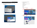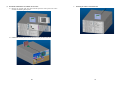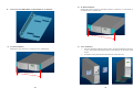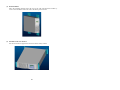
1
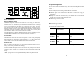
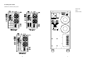
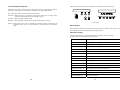
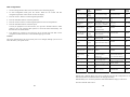
EMC Statements
CISPR 22
4K VA – 20K VA UPS
NOTICE: Pursuant to CISPR 22 rules, this product has been tested and thereby complies
with the conditions of a Class A digital device, which have been established for offering
sufficient protection against dangerous interference for installation in a residential area.
Installation and use of the equipment should comply with the instructions provided in order
to avoid such interference due to the amount of radio frequency energy that is radiated and
generated by the equipment. In spite of this, we cannot assure that a certain amount of
interference may not occur in some installations. If, by turning on and off, it can be deduced
that your radio or television reception is found to be influenced by harmful interference from
the equipment, it is recommended to use one of the following preventive measures:
z Place the receiving antenna in a separate location or orientation.
z Ensure a greater distance is achieved between the receiver and the equipment.
z Ensure that your equipment is connected to an outlet on a separate circuit than the
receiver.
z Contact a technician experienced with radio and TV or a dealer for further assistance.
Declaration of Conformity Request
Units labeled with a CE mark comply with the following standards and directives:
z Harmonic Standards: EN 50091-1-1 and EN 50091-2
z EU Directives:73/23/EEC, Council Directive on equipment designed for use within
certain voltage limits
93/68/EEC, Amending Directive 73/23/EEC
89/336/EEC, Council Directive relating to electromagnetic compatibility
92/31/EEC, Amending Directive 89/336/EEC relating to EMC
The EC Declaration of Conformity is available upon request for products with a CE
mark.
■User’s and Installation Manual■
I
CONTENTS
1. Introduction ...........................................................................................1
2. System description...............................................................................1
2.1 General description......................................................................................1
2.2 System configuration ...................................................................................3
3. Safety information ................................................................................4
4. Storage...................................................................................................5
IMPORTANT SAFETY INSTRUCTIONS
SAVE THESE INSTRUCTION
● CAUTION (UPS Having Internal Batteries): Risk of electric shock Hazardous live parts inside this unit are energized from the battery supply
even when the input AC power is disconnected.
●
CAUTION (No User serviceable Parts):
●
CAUTION (Non-isolated Battery supply):
5. Installation .............................................................................................5
5.1 Environment ................................................................................................5
5.2 Rear panel views .........................................................................................6
5.3 Connection to mains and loads (4000 - 20000 VA)....................................12
●
5.4 Default settings at the factory ....................................................................16
Risk of electric
shock, do not remove cover. No user serviceable parts inside. Refer
servicing to qualified service personnel.
Risk of electric
shock, battery circuit is not isolated from AC input, hazardous voltage may
exist between battery terminals and ground. Test before touching.
WARNING (Fuses):
To reduce the risk of fire, replace only with the
same type and rating of fuse.
6. Computer and alarm connections ....................................................17
●
6.1 EPO port (emergency power off) ...............................................................18
●
WARNING: Intend for installation in a controlled environment.
CAUTION:
Do not dispose of batteries in a fire, the battery may
explore.
7. User’s guide to operations ................................................................18
●
CAUTION:
●
7.4 Interpreting UPS messages.......................................................................25
CAUTION: A battery can present a risk of electric shock and high short
circuit current. The following precaution should be observed when working
on batteries
7.5 Trouble shooting ........................................................................................26
Remove watches, rings or other metal objects.
7.1 Starting and shutting down the UPS ..........................................................18
7.2 Button operation ........................................................................................19
7.3 Control panel functions ..............................................................................20
8. Maintenance ........................................................................................27
9. Technical Specifications ....................................................................28
10. VGD RM 6KVA(3U+3U) Mechanical...................................................34
Do not open or mutilate the battery, released electrolyte is
harmful to the skin and eyes.
Use tools with insulated handles.
● To reduce the risk of electric shock, disconnect the UPS from the mains
supply before installing a computer interface signal cable. Reconnect the
powers cord only after signaling interconnections have been made.
● Servicing of batteries should be performed or supervised by personnel
knowledge of batteries and the required precautions. Keep unauthorized
personnel away from batteries.
II
III
The instructions contained within this safety manual are deemed important and should be
closely followed at all times during installation and follow-up maintenance of the UPS and
batteries.
CAUTION
The unit has a dangerous amount of voltage. If the UPS indicator is on, the unit’s
outlets may have a dangerous amount of voltage even when not plugged into the
wall outlet because the battery may continue to supply power.
Care should be taken to undertake installation indoors free from
electrically-conductive particles which is under temperature and humidity control
in order to reduce the risk of electric shock.
It is best to disconnect the device using the power supply cord. Ensure that the
equipment is placed in a position near the outlet where easily accessible.
Except replacing the batteries, all servicing on this equipment must be carried out
by qualified service personnel.
Before conducting any maintenance, repair or shipment, first ensure that
everything is turned off completely and disconnected.
For additional safety instructions, please use the Safety Manual as reference.
Special Symbols
The following symbols used on the UPS warn you of precautions:
RISK OF ELECTRIC SHOCK – Please observe the warning that a risk of electric
shock is present.
CAUTION: REFER TO OPERATOR’S MANUAL - Refer to the operator’s
manual for additional information, such as important operating and maintenance
instructions.
1. Introduction
The information provided in this manual covers single phase 5000 – 20000 VA,
uninterruptible power systems, their basic functions, operating procedures, and emergency
situations, also including information on how to ship, store, handle and install the equipment.
Only detailed requirements of the UPS units are described herein, and installation must be
carried out in accordance with this manual. Electrical installations must also carefully follow
local legislation and regulations. Only qualified personnel should conduct these installations
as failure to acknowledge electrical hazards could prove to be fatal.
2. System description
Several different kinds of sensitive electrical equipment stay protected by a UPS
(Uninterruptible Power System) including computers, workstations, process control systems,
telecommunications systems, sales terminals, other critical instrumentation, etc. The purpose
of the UPS is to protect these systems from poor quality utility power, complete loss of
power, or other associated problems.
Electrical interference abounds in many forms causing problems in AC power, from
lightning, power company accidents and radio transmissions to motors, air conditioners, and
vending machines, among others. So protection of sensitive electrical equipment is vital to
protect against power outages, low or high voltage, slow voltage fluctuations, frequency
variations, differential and common-mode noises, transients, etc.
In order to prevent power line problems reaching critical systems causing damage to
software, hardware and causing equipment to malfunction, the UPS helps by maintaining
constant voltage, isolating critical load output if needed, and cleaning the utility AC power.
2.1 General description
SAFE GROUNDING TERMINAL - Indicates primary safe ground
As a double conversion on-line UPS, it is able to supply uninterrupted, clean single-phase
power to your critical systems while keeping batteries charged continuously, regardless of
whether utility power fails or not.
LOAD ON/OFF - Pressing this button turns on/off the output receptacles and the
Indicator light.
In event that a power failure lasts longer than a UPS backup time, it will shut down avoiding
battery discharge, and as soon as voltage comes back, the UPS will automatically charge up
and start recharging the batteries.
Please do not discard the UPS or UPS batteries as the UPS may have valve
regulated, lead–acid batteries. Please recycle batteries.
As shown in fig.1 block diagram:
z An input filter reduces transients on the mains
z For maintaining full battery charge, AC-power is rectified and regulated in the rectifier
feeding power to the inverter and battery converter.
z DC power is converted to AC in the inverter passing it on to the load.
z Power is maintained from the battery during a power failure.
z The converter increases voltage appropriately for the inverter.
IV
1
2.2 System configuration
Filter
PFC&Booster
Charger &
Battery
switch
Battery
Inverter
By-pass
switch
Control
&
Monitoring
Filter
Monitoring
panel
RS232 or
USB
Slot
The UPS device and the internal backup battery make up the system. Depending on the site
and load requirements of the installation, certain additional options are available as a tailored
solution.
Planning a UPS system, the following should be taken into consideration:
z The total demand of the protected system shall dictate the output power rating (VA).
Allow a margin for future expansion or calculation inaccuracies from measuring power
requirements.
z Backup time needed will indicate the battery size needed. If load is less than the UPS
nominal power rating then actual backup time is longer.
z The following options are available:
Fig.1. Block diagram
z External Battery Cabinets
Efficiency Optimizer function
z Transformer cabinets
The Efficiency Optimizer function is a new feature for the UPS adding cost effectiveness,
minimizing power loss and reducing power consumption. Alternating between bypass and
on-line modes is achieved automatically and in accordance with the conditions of the utility
power. On-line mode may be used during times of intermittent power supply, and bypass
mode when power flows smoothly in order to obtain greatest efficiency. Irregularities can be
detected in less than a second, and on-line mode reactivated immediately. Switching back to
online mode occurs when input voltage is outside ±10% or nominal (±15% selectable), when
input frequency is outside of ±3Hz or when no input line is available.
Although high efficiency is standard, the default operation is in on-line mode. Bypass can be
activated in the LCD panel, though on-line can be run permanently if preferred.
Free Run Mode
The UPS operates in free run mode when input frequency is outside of the selected input
frequency range. Free run mode is when output frequency does not match input frequency.
When starting the UPS, the frequency regulation detected is 50 or 60 Hz ±0.25Hz. Please
refer to chapter 7.2 if you want bypass available while running in free run mode.
Diagnostic tests
When you start the UPS, a diagnostic test is automatically executed that checks electronics,
battery, and reports any problems on the LCD display.
z Maintenance bypass switches
z Connectivity options (relay card, SNMP/WEB card)
The following UPS models are available
Model
Backup time
Internal batteries
Recharge time to 90% capacity
UPS 4000VA
4min
4 hours
UPS 5000VA
4min
4 hours
UPS 6000VA
7min
4 hours
UPS 8000VA
4min
4 hours
UPS 10000VA
4min
4 hours
UPS 12000VA
8min
4 hours
UPS 15000VA
6min
4 hours
UPS 20000VA
4min
4 hours
Additional External Battery Cabinets are available if more back-up time is needed.
An advanced battery management system always monitors the conditions of the batteries
sends any forewarnings if replacement is needed. Otherwise every 30 days of normal mode
operation, a battery discharge test is performed and any problems reported on the LCD
display.
Except during the first 24 hours after startup while the UPS is in charging mode (please see
chapter 7.2), diagnostic tests can be performed manually from the front panel at any time.
2
3
3. Safety information
4. Storage
Information presented here is vital to all personnel and please also read the UPS safety
manual.
Please adhere to the following instructions if the UPS is not installed immediately:
Storage and Transportation
z Do not store in temperatures outside the range of +15°C to +25°C.
Please handle with extreme caution since a high amount of energy is contained with the
batteries. Always keep the unit in position as marked on the packaging and never drop the
unit.
z Ensure that the equipment is fully protected from wet or damp areas and from moist air.
z Store the equipment as is in its original packing and shipping carton
In order to maintain the vitality of the batteries, ensure that the UPS is recharged every 6
months for at least 8 hours.
Installation
If flammable substances such as gases or fumes are present or if the room is airtight, a safety
hazard situation exists, in which no electrical equipment should be operated.
The instructions in this manual explain how to install the UPS safely. Not acknowledging
such electrical hazards may be fatal, so keep this manual for all future reference.
5. Installation
5.1 Environment
Ensure that all environmental concerns and requirements are met according to these
technical specifications, otherwise the safety of installation personnel cannot be
guaranteed and the unit may malfunction.
WARNING!
Ensure that you remember the following when locating the UPS system and battery options:
It is strongly advisable not to open the UPS cabinet as the components have very
high voltage and touching them may be fatal. Only a technician from the
manufacturer or an authorized agent may service the unit.
This UPS unit’s output receptacles carry live voltage even when not connected to a
power supply as it has its own energy source.
z Avoid extremes of temperature and humidity. Maximal battery life can be attained with a
recommended temperature range of 15 °C to 25 °C.
z Provide protection for the equipment from moisture.
z Space and ventilation requirements must be met. Ensure there is 100mm behind and
50mm on the sides of the UPS for ventilation.
z Ensure that the front of the UPS remains clear for user operation.
User’s operations
The External Battery Cabinets has to be installed next to the UPS or under the UPS.
The only operations that users are permitted to do are:
z Turning the UPS unit on and off
Caution! The UPS and the External Battery Pack are to be installed at the same location.
In case, the UPS and the External Battery Pack are installed outside of visible distance, then
subject to the local inspection authority, User will need to add a Safety disconnect adjacent
to the UPS to provide safety isolation.
z Operating the users interface
z Connecting data interface cables
All such operations are to be performed exactly as instructed in this manual. The greatest
care possible must be taken for any of these operations and any change thereof may prove
very hazardous to the operator.
4
5
5.2 Rear panel views
4K/5KVA (120VDC) Rear panel
6KVA Rear
panel
(Without ISO)
6
7
8
6KVA Rear
panel
8K~10KVA
Rear panel
(With ISO)
(Without ISO)
9
8K~10 KVA
Rear panel
12KVA Rear panel
(ISO and With ISO)
(With ISO)
10
11
5.3 Connection to mains and loads (4000 - 20000 VA)
15/20 KVA Rear panel
(ISO and With ISO)
Only qualified specialists or technicians who conform to applicable safety
standards may carry out the installation of this equipment. The installation must
further comply with all local legislation and regulations.
Follow all installation and safety instructions very carefully, otherwise those
performing installation may suffer from a hazardous situation and the UPS or
load connections may also be damaged.
The high voltage and current contained within the UPS equipment can injure
or kill personnel and damage equipment.
For electrical installation, closely observe the nominal current rating of the source.
Installing External battery cabinets
z
First disconnect the UPS from mains and loads before attempting an
External Battery Cabinet installation.
z
Use the battery cable provided with the External Battery Cabinet to
connect the External Battery Cabinet to the UPS. Connect a second
battery cabinet to the first one with the cable provided if more than one is
to be installed.
z
Be aware of UPS parameters and changing the Battery pack quantity
when using the external battery cabinets (see chapter 7.2)
Installing UPS
12
z
Ensure that the installation site has all electrical connections properly
carried out. In addition, refer to figures 2 and 3 to check the fuse and
cable dimensions.
z
Isolate and secure the source against reclosing. Both input and output
circuit breakers (located in the back) must be “OFF”.
z
Refer to figure 2 for single cable input and figure 3 for dual cable input.
Connect the UPS according to these diagrams. If installing dual cables,
the interconnection jumper (b*) needs to be removed as in figure 2. Fuse
and cable sizes are given in figure 3.
z
During installation, if it cannot be determined that neutral is grounded or
the identification of the neutral status of the mains supply is unreliable,
an additional two pole disconnect device is necessary in the building
installation.
z
At the back of the unit you will find the Emergency Power Off (EPO),
which when open will immediately shut down the logic circuit output of
the UPS as in figure 2 and 3. Wiring the EPO signal is optional.
z
Caution! Local safety requirements may require a separate external
Emergency Power Off that opens output circuit breakers, and if so, use
13
figures 2 and 3 for proper installation. Refer to local wiring rules.
z
Should computer or alarm connections be used, use connections
according to chapter 6 of the manual provided with that option. The
connections can be referred to on the rear panel.
z
The installation is now complete.
b*) removable jumper when dual input used
Fig. 2
Fig. 3.
* Only required if demanded by that of local wiring rules.
14
15
5.4 Default settings at the factory
6. Computer and alarm connections
On the LCD display you will find several of the UPS parameters to select.
Default settings are as follows:
At the back of the UPS is an interface allowing direct communication with your computer
system, the location of which can be found in figure 4. There is a RS232 serial data
interface, one USB data interface and an emergency power off switch supplied. However,
the RS232 port cannot be used when the USB interface is in use.
Settings
Selection
Factory default
Output Voltage Setting
208/220/230/240 Vac 230V (FOR HV series)
In addition there is an optional interface slot that allows you to install different
communications cards. It can be used parallel with either the RS232 or USB ports.
Input/Bypass Voltage
±10%
+10/-15%
+15/-20%
+10/-15%
Currently there are two cards available for the optional interface slot. An SNMP/WEB
card allows management and monitoring over a network or internet, and the AS/400 card
allows voltage free relay contacts. Your local dealer will have more information about
these option cards.
Input/Frequency
±2%
±5%
±7%
±5%
HE Mode Setting
On/Off
Off
Free Run Mode
On/Off
On
Connecting the UPS to a Computer
Bypass Enable/Disable at free run mode Disable/Enable
Disable
Alarm silence
On/Off
Off
Site wiring alarm
Enable/Disable
Disable
External Battery pack setting
0, 1, 2
0
The communication device for the UPS and PC comes as a complete package with power
management software. Only the communication cable provided with UPS may be used to
connect to your computer, which is accomplished through the UPS RS232 port. Also
ensure that the operating system on your computer is supported. Instructions provided in
the power management software will help with this installation.
Other advanced power protection solutions such as SNMP are provided by your dealer.
RS-232 Standard Interface port
You may change default settings, but we recommend that this is done after installation and
before starting up loads. Read UPS configurations in chapter 7.2 for more information.
The RS-232 interface uses a 9-pin female D-sub connector. This information consists of
data about utility, load and the UPS. The interface port pins and their functions are
identified in the following table.
Pin #
Signal name
Direction (re UPS)
Functions
2
TxD
Output
TxD Output
3
RxD
Input
RxD / Inverter Off Input
5
Common
6
CTS
Output
Ac Fail Output
8
DCD
Output
Low Battery Output
9
RI
Output
+12 VDC Power
Common
Caution! Max rated values 12Vdc/50mA
Fig.4
16
17
USB port (option)
Connecting the UPS to your computer is accomplished through the USB port on the back
of your computer. USB compliant hardware and operating system will be necessary
including installation of a UPS driver. The serial port cannot be used when using the USB
port. The USB cable is standard and can be bought separately.
7.2 Button operation
Please note the five operating buttons on the front panel:
1.
(a) Push “ON/OFF” button (at least 1 seconds) to turn on the UPS.
6.1 EPO port (emergency power off)
A customer-supplied switch located remotely can be used to open the EPO connection
and allows UPS output receptacles to be switched off. Since the EPO shuts down the
equipment immediately, orderly shutdown procedures are not followed and not by any
power management software. The UPS will have to be manually restarted in order to
regain power to the outlets.
“ON/OFF” button:
(b) When UPS is working, push the “ON/OFF” button(at least 2 seconds) to turn
off the UPS.
2.
“STATUS” button:
Use this button to check content of UPS and the method is listed below:
(a) Push the “STATUS” button (at least 2 seconds) to check content of UPS.
Each content can be displayed by pressing at once, and it has fifteen kinds of
7. User’s guide to operations
Necessary information for operation of the unit is covered in this chapter.
Normally the UPS runs automatically, but on those few occasions such as
just after installation, all the starting and shutting down procedures are
described herein.
function to be checked.
(b) If no pressing within 10 seconds, it will return to original status.
3.
“FUNC” button:
Each function can be enabled by pressing this button & “ENTER” button.
7.1 Starting and shutting down the UPS
(a) Push the “FUNC ” button (at least 2 seconds) to choose which function that
Starting the UPS
you want. Each content can be displayed by pressing at once, and it has
z Ensure that installation was correct and successful and that the input power cable is
connected to a well-grounded outlet.
fourteen kinds of function to be checked.
z The UPS can be started by pushing the “ON/OFF” button on the front panel.
(b) After choosing the function, push the “ENTER” button to enter the function
z The UPS should now start its inspection of: internal functions, main synchronization
and inverter startup. Then power should start to be supplied via the terminal block.
that you want.
(c) Push the “FUNC” button to choose other function again.
z During this inspection, the LCD will display “Ready on”. The LED shall light up
when output power has commenced and the LCD will display “Line mode”.
(d) Push the “ENTER” button to enable your function.
z Switch on the loads.
(e) Push the “ENTER” button to confirm and enable your function.
Shutting down the UPS
(f)
z Shut down and turn off the loads.
4.
z Push the “ON/OFF” button on the front panel for two seconds. The alarm will sound
and the UPS will shut down.
z The LCD will display UPS OFF for a few seconds.
z In emergency situations, the EPO located on the back of the unit should be used.
18
If no pressing within 10 seconds, it will return to original status.
“ENTER” button:
Use this button to enter、enable or confirm the function that you want.
5.
“ESCAPE” button:
Use this button to return to main display(Line mode or Battery Mode).
19
Status of the UPS, measurements and alarms are all indicated on the LCD screen.
7.3 Control panel functions
Operation of the UPS is indicated on the monitor panel with five LED indicators and an
LCD screen. This display is also capable of alerting the user with audible alarms.
ON:This green LED is lit when UPS has been turned on.
ON-LINE:When the UPS is in normal or static bypass modes, there is voltage at the
output terminals and this LED will light up in green.
ON-BAT:While operating in battery mode.
BYPASS:While operating in bypass mode, this LED will light up in yellow.
FAULT:If any internal error occurs in the UPS, this LED will light up in red and give off
an audible alarm. Press any of the buttons on the front panel to turn off the
alarm.
Control panel
Normal display
The UPS status is shown in normal display mode. From here you have a choice to go to UPS
meters display and the Setting display by pushing the button.
UPS meters display
Various measurements are available through the UPS meters display; pressing
the button will scroll through the following meters:
LCD message
Description
O/P VOLT= xxx, xV
Shows Output AC voltage
O/P FREQ= xx, x Hz
Shows Output Frequency
I/P VOL T= xxx, xV
Shows Input AC voltage
I/P FREQ= xx, x Hz
Shows Input Frequency
BAT VOLT= xx,xV
Shows Battery Voltage
O/P LOAD%= xx%
Shows Load % of max load
O/P W= xW
Shows Output Watts
O/P VA= xVA
Shows Output VA
O/P CURR= xA
Shows Output Current
BACKUP TIME= xx min Shows Estimated Backup time in minutes
20
BAT CHARG= xx%
Shows approximate percentage of Battery capacity
TEMPERATURE= xxC
Shows approximate ambient temperature
BAT PACK NUM= x
Shows External Battery Pack Number
RATING = xxxxVA
Shows UPS Rating
CPU VERSION xx.x
Shows CPU Version
21
UPS configurations
1. Various settings that have been chosen are shown in the UPS setting display.
Settings
LCD
display
Explanation
Selection
Factory
default
2. To enter configuration mode, press the “FUNC” button for one second. The first
configuration parameter will be shown on the LCD display.
Output Volt.Setting
O/P V
Setting
Select Nominal Voltage
208/220/230/240 V
230V
Input/Frequency
Select input frequency
I/P F Setting range when UPS goes into
free run mode
Input/Bypass
Voltage
I/P Bypass
Set
Select Input Voltage range
when bypass is available
Free Run Mode
Free Run
Set
Select if UPS can run in
Free run mode
(unsynchronized)
7. If no buttons are pressed (or user inactivity) for ten seconds, the UPS shall exit the
configuration mode and return to normal mode displaying Line mode.
Bypass
Enable/Disable at
Free run mode
Bypass
disable
If Enable is chosen, the
UPS can go to bypass when Disable/Enable
unsynchronized.
Disable
Caution!
He mode Setting
HE Mode
Set
Select if UPS runs in high
efficiency mode
ON/OFF
OFF
Force Manual
Bypass
Manual
bypass
Permanently force UPS to
ON/OFF
bypass. For service only.**
OFF
Do Battery Test
Battery Test
Detect battery is normal or
not.
Silence Function
Silence Set
Enable or disable silence
function
Number of
External battery
Packs
This setting is needed
Bat Cabinet
For UPS to predict
Set
Backup time
Site wiring alarm
Sit Fault Set
Select Language
Language
3. Press the “FUNC” button to scroll through the parameters.
4. Press the “ENTER” button to select the parameter.
5. Press the “FUNC” button to scroll through the options for the selected parameter.
6. Press the “ENTER” button to select the option.
You may be prompted to save the selection, if so press the “ENTER” button to either
confirm or save your selection. Other options are saved and started automatically. See
the table below for further details.
The factory default settings do not necessarily have to be changed, although you are free to
tailor the UPS to your specific needs.
±2%
±5%
±7%
±10%
+10/-15%
+15/-20%
ON/OFF
±5%
+10/-15%
ON
ON/OFF
OFF
0 (only internal batteries)
1(one external cabinet)
2 (two external cabinets)
0
You can enable or disable
the site wiring alarm
Enable /Disable
Disable
Select load language
English, German, French,
English
Spanish, Italian.
Set Generator Mode Generator
Set unit in generator mode.
ON/OFF
***
OFF
Set RS232
communication
Set RS232 communication
enable or disable
Enable
RS232
Control
Enable/Disable
Manual test of the UPS
Manual UPS or Manual Battery tests can be conducted from the UPS configuration as well
and are functional even when the UPS is not charging the battery.
Manual Battery test: Scroll the parameters until Manual Bat test displays on the LCD.
Press the “ENTER” button twice.
22
23
**) Note: In order for the UPS and power management software to operate normally,
Manual Bypass should always be set to OFF as the load will not be protected by the unit
when Manual Bypass is ON. This is aimed for operating an external maintenance bypass
switch.
7.4 Interpreting UPS messages
***) Note: You should turn UPS off and keep the AC power before you use “Generator”
function. (even you want to select “\Generator\OFF” to back to normal mode).
Start the troubleshooting procedure if you witness any alarm indication on the control panel.
Troubleshooting procedures described here give simple instructions in determining UPS
malfunctions.
Alarm indicators
The UPS gives the following audible alarms:
z If UPS is on battery and the ON BATTERY LED is on, UPS will beep every 5 seconds.
z If the battery capacity is low and the ON BATTERY LED is flashing, the UPS will beep
twice every 5 seconds.
z If UPS is on bypass and the BYPASSED LED is on, UPS will no beep.
z If UPS has an internal fault and the ALARM LED is on, the UPS will give a constant
audible alarm displaying the cause on the LCD display.
Silencing an alarm
By pressing any of the three buttons on the front panel, the alarm can be turned off, except
when the battery is low, which will cause the alarm to resound.
On the LCD display, you can also choose silent alarm mode which will not warn you of any
malfunction audibly.
24
25
8. Maintenance
7.5 Trouble shooting
Displayed on LCD
Output Overload
Audible Alarm Alarm Description
The UPS is overloaded (in
Line Mode). Your
Two Beeps per equipment needs more
power than the UPS can
second
provide. The UPS operates
in bypass.
Battery Test
No Beeps
The UPS is doing a battery
test.
Over-Charge
Constant beep
Batteries are
overcharged.
Low Battery
2 beeps every
5seconds
On-Battery
Charger Failure
Once every 5
seconds
Constant beep
Over-Temperature
Constant beep
Output Short
High output Voltage
Low Output Voltage
Constant beep
Constant beep
Constant beep
Bus Fault
2 Beeps per
second
Site wiring Fault
1 Beep per
second
Line abnormal
1 Beep per
second
The unit is operating on
Battery Power and will shut
down soon due to very low
battery voltage
The unit is operating on
Battery Power.
Charger has failed.
What You Should Do
Shut off the least important
equipment connected to the
UPS. If this solves the
overload problem, the UPS
will switch from bypass back
to normal operation.
No action needed. The UPS
will return to normal operation
when it successfully completes
the battery test.
Turn off protected loads. Turn
off UPS and call your local
dealer
The unit will restart
Automatically when
acceptable power returns.
Save your data and perform a
controlled shutdown.
Phone the local dealer
Make sure the unit’s fans and
vent holes are not blocked, and
make sure the ambient
surrounding temperature is not
High ambient Temperature.
above 40 degree C. If these
conditions did not solve the
problem, call your service
representative.
Output short circuit
Call the Local dealer
High output voltage
Call the Local dealer
Low output voltage
Call the Local dealer
Turn off protected loads. Turn
High internal DC bus
off UPS and call your local
Voltage.
dealer
UPS mains connector polarity
Wrong. Rotate the connector
Voltage detected Between (Schuko). UPS installed to
mains supply without ground.
Neutral and Ground
See page 15 on how to disable
the Site wiring alarm
Wrong AC Line backed up
during auto restart
26
With a minimal amount of maintenance, you can expect the UPS to application, otherwise
consider changing the batteries. have a long life free of trouble. The most critical issues for
the reliability of the UPS are environmental issues. Ensure that the temperature and humidity
are always according to specifications and keep the area around the unit clean and dust free.
At a temperature of 25°C, the typical battery lifetime is 4 years.
Also check at regular intervals of 6 to 12 months whether the back-up time of the battery is
adequate for its
WARNING!
Batteries may cause electrical shock or burn from high short circuit
currents. Please observe the following precautions: 1. Remove jewelry and metal
objects such as watches and rings. 2. Use tools that have insulated handles. 3. Keep
tools and other metal objects from contacting and away from the batteries.
ELECTRIC ENERGY HAZARD. Do not attempt to rewire, alter, or change any
battery wiring or connectors. Attempting to make such alterations can cause
injury.
Replace the batteries with the same number and type as originally installed
batteries.
DO NOT DISCONNECT the batteries while UPS is in Battery mode.
27
9. Technical Specifications
For model with 3 Phase in 1 Phase out
Tower model (with LCD display)
Capacity
8K31
10K31
12K31
15K31
20K31
Capacity (VA)
8000VA
10000VA
12000VA
15000VA
20000VA
Capacity (W)
5600W
7000W
8400W
10500W
14000W
Environment
Input
Voltage/Load
208~241V
0~25%
242~276V
0~40%
277~311V
0~75%
Frequency
Voltage (on battery)
Battery
Battery Protection
Physical
3:1
125% for 1 minutes and 150% for 10 seconds 130% for 10 seconds and 150% for 1.5
seconds (On-battery)
Input / output voltage, input / output frequency, on-line mode, back up mode, battery
capacity, load level
Net Weight kg (lb) W/O
ISOTR
Shipping Weight kg (lb)
W/O ISOTR
Dimensions W x D x
H mm (inch) W/
ISOTR
Net Weight kg (lb)
W/ ISOTR
System/Display
/Warning
RS-232 Serial Port and USB
240V /
12V9AH x 20
x 2SET
4 hours
Self-test, adjustable battery transfer points and alarm settings
Battery
Cut off without draining any current when battery is low
YES
About 4~6 min Full load / 10~15min Half load
342 x 863 x 905
(13.5" x 34.0" x 35.6")
80.0 (176.0)
176.5 (388.3)
175.0 (385.0)
101.5 (223.3)
206.5 (454.3)
196.0 (432.3)
342 x 690 x 715
(13.4" x 27.2" x 28.1")
342 x 690 x 878
(13.5"x27.2"x34.6")
342 x 863 x 905
(13.5" x 34.0" x 35.6")
130.0 (286.0)
176.5 (388.3)
225.0 (495.0)
28
Surge Protection
Overload
Protection
Short Circuit
Protection
Visual Display
(LED model)
Visual Display
(LCD model)
Audible Alarm
(Battery back-up)
UPS Fault
VGD-4000
VGD5000
VGD-6000
VGD-8000
4000VA
5000VA
6000VA
8000VA
2800W
3500W
4200W
5600W
208V, 220V, 230V, 240V +/-2% (Selectable Output Voltage) For 4K / 5K / 6K
100V, 110V, 115V, 120V / 208V, 220V, 230V, 240V +/-2% (Selectable Output Voltage)
For 6K / 8K with output isolation transformer
50 / 60 Hz +/-0.5%
0 ms
Auto transfer to UPS
> 95 %
> 97 %
On-Line / Fully digitized microprocessor controlled
Sine wave
< 3% of T.H.D. at linear load
3:1
IEC61000-4-5 level 3
125% for 1 minutes and 150% for 10 seconds (On-line) 130% for 10 seconds and 150%
for 1.5 seconds (On-battery)
UPS output cut off immediately or input fuse / circuit breaker protection
UPS on(green), line-mode(green), battery mode(yellow), bypass(yellow), fault(red)
Input / output voltage, input / output frequency, on-line mode, back up mode, battery
capacity, load level
Beep every 5 sec
Continuous beeping sound and LCD display
Communication
RS-232 Serial Port and USB
Type
DC Voltage (V)
Battery (Tower )
Sealed, maintenance-free lead acid batteries
Management
Hardwire
342 x 690 x 878
(13.5"x27.2"x34.6")
0 ~ 95% humidity, non-condensing
120V / 12V7AH
x 10
120V / 12V9AH
x 10
Typical Recharge
Time to 90% Full
Hardwire
257 x 690 x 715
(10.1" x 27.2" x 28.1")
< 55 dB
Crest Factor
Protection and
Filtering
Beep every 5 sec
Continuous beeping sound and LCD display
Receptacles
3,500 meters max
Harmonic distortion
UPS output cut off immediately or input fuse / circuit breaker protection
UPS on(green), line-mode(green), battery mode(yellow), bypass(yellow), fault(red)
240V /
12V7.2AH x
20
-20~50°C / -4~122°F
Overload Recovery
High Efficiency
mode (AC to AC)
UPS Design
Technology
Output Wave Form
IEC61000-4-5 level 3
Sealed, maintenance-free lead acid batteries
240V /
240V /
240V /
12V7.2AH x 20 x
12V7.2AH x
12V9AH x 20
2SET
20 x 2SET
0~40°C / 32~104°F
Frequency (on
battery)
Transfer Time
< 3% of T.H.D. at linear load
Cold Start (DC start)
Back Up Time (Tower
model)
Input Inlet
Dimensions W x D x H
mm (inch) W/O ISOTR
Voltage (on battery)
Sine wave
Type
Typical Recharge Time
to 90% Full
Management
Output
> 97 %
Communication
Capacity (VA)
Capacity (W)
On-Line / Fully digitized microprocessor controlled
Surge Protection
DC Voltage (V) Battery
(Tower )
Capacity
Auto transfer to UPS
Crest Factor
246.5 (542.3)
For Tower model
Tower model (with LCD display)
0 ms
Harmonic distortion
System
Display/
Warning
0~100%
50 / 60 Hz +/-0.5%
Overload Recovery
High Efficiency mode
(AC to AC)
UPS Design
Technology
Output Wave Form
Short Circuit Protection
Visual Display (LED
model)
Visual Display (LCD
model)
Audible Alarm (Battery
back-up)
UPS Fault
312~478V
206.5 (454.3)
Relative Humidity
100V, 110V, 115V, 120V / 208V, 220V, 230V, 240V +/-2% (Selectable Output Voltage)
Transfer Time
Protection
and Filtering Overload Protection
Load Capacity
50/60 Hz Auto Sensing
Frequency (on battery)
Output
Voltage/Range
151.5 (333.3)
Audible Noise (1
meter from surface)
208/360V, 220/380V, 230/400V, 240/415V(3Ф5W)
Load Capacity
Shipping Weight kg
(lb) W/ ISOTR
Operating
Temperature
Storage
Temperature
Altitude
Physical
Battery Protection
Cold Start (DC
start)
Back Up Time
(Tower model)
Input Inlet
Receptacles
Dimensions W x D
x H mm (inch) W/O
ISOTR
240V / 12V7.2AH
x 20
240V / 12V7.2AH
x 20
4 hours
Self-test, adjustable battery transfer points and alarm settings
Cut off without draining any current when battery is low
YES
4 min. Full load /
10 min. Half load
5 min. Full load /
About 4~6 min Full load / 10~15min Half load
13 min. Half load
Hardwire
IEC C13*8 ; C19*2
257*537*440
(10.1”x21.1”x17.3”)
29
Hardwire
257 x 690 x 715
(10.1" x 27.2" x
28.1")
257 x 590 x 570
(10.1"x23.2"x22.4")
Environment
Net Weight kg (lb)
W/O ISOTR
Shipping Weight kg
(lb) W/O ISOTR
Dimensions W x D
x H mm (inch) W/
ISOTR
Net Weight kg (lb)
W/ ISOTR
Shipping Weight kg
(lb) W/ ISOTR
Operating
Temperature
Storage
Temperature
Altitude
50 (110)
86.0 (189.2)
53 (116.7)
106.0 (233.2)
101.5(223.3)
257 x 590 x 700
(10.1"x23.2"x27.6")
342 x 690 x 715
(13.4" x 27.2" x
28.1")
123.0 (270.6)
130 (286.0)
145.0 (319.0)
151.5 (333.3)
Physical
0~40°C / 32~104°F
-20~50°C / -4~122°F
3,500 meters max
Audible Noise (1
meter from surface)
50 dBA
< 55 dBA
Relative Humidity
Conformance
80(176)
0 ~ 95% humidity, non-condensing
Safety
UL 1778, CE
EMC (EMS / EMI)
Equipment
Protection Policy
Environment
IEC 61000-4, FCC Part 15, CISPR 22
Warranty policy may vary depends on region
Cold Start (DC
start)
Back Up Time
(Tower model)
Input Inlet
Receptacles
Dimensions W x D
x H mm (inch) W/O
ISOTR
Net Weight kg (lb)
W/O ISOTR
Shipping Weight kg
(lb) W/O ISOTR
Dimensions W x D
x H mm (inch) W/
ISOTR
Net Weight kg (lb)
W/ ISOTR
Shipping Weight kg
(lb) W/ ISOTR
Operating
Temperature
Storage
Temperature
Altitude
YES
About 4~6 min Full load / 10~15min Half load
Hardwire
Hardwire
257 x 690 x 715
(10.1" x 27.2" x
28.1")
342 x 690 x 905
(13.5"x27.2"x35.6")
342 x 760 x 905 (13.5" x 29.9" x 35.6")
80 (176)
130 (286)
207 (455.4)
101.5 (223.3)
151.5 (333.3)
225 (495.0)
342 x 690 x 715
(13.4" x 27.2" x
28.1")
342 x 690 x 905
(13.5"x27.2"x35.6")
342 x 760 x 905 (13.5" x 29.9" x 35.6")
130 (286)
180 (396)
274 (602.8)
151.5 (333.3)
201.5 (443.3)
292 (642.4)
0~40°C / 32~104°F
-20~50°C / -4~122°F
3,500 meters max
Audible Noise (1
meter from surface)
Tower model (with LCD display)
Capacity
Capacity (VA)
Capacity (W)
Output
VGD-10000
VGD-12000
VGD-15000
VGD-20000
10000VA
12000VA
15000VA
20000VA
7000W
8400W
10500W
14000W
Voltage (on battery)
Frequency (on
battery)
Transfer Time
100V, 110V, 115V, 120V / 208V, 220V, 230V, 240V +/-2% (Selectable Output Voltage)
Overload Recovery
High Efficiency
mode (AC to AC)
UPS Design
Technology
Output Wave Form
Auto transfer to UPS
System/Display
/Warning
Short Circuit
Protection
Visual Display (LED
model)
Visual Display
(LCD model)
Audible Alarm
(Battery back-up)
UPS Fault
Type
DC Voltage (V)
Battery (Tower )
Battery Protection
RM model (with LCD display)
On-Line / Fully digitized microprocessor controlled
Capacity
Output
< 3% of T.H.D. at linear load
3:1
IEC61000-4-5 level 3
125% for 1 minutes and 150% for 10 seconds (On-line) 130% for 10 seconds and 150%
for 1.5 seconds (On-battery)
UPS output cut off immediately or input fuse / circuit breaker protection
UPS on(green), line-mode(green), battery mode(yellow), bypass(yellow), fault(red)
Input / output voltage, input / output frequency, on-line mode, back up mode, battery
capacity, load level
IEC 61000-4, FCC Part 15, CISPR 22
Warranty policy may vary depends on region
RS-232 Serial Port and USB
Sealed, maintenance-free lead acid batteries
240V / 12V7.2AH
x 20 x 2SET
240V / 12V9AH
x 20 x 2SET
4 hours
Self-test, adjustable battery transfer points and alarm settings
Cut off without draining any current when battery is low
30
VGD5000
VGD-6000
VGD-10000
4000VA
5000VA
6000VA
10000VA
2800W
3500W
4200W
7000W
Voltage (on battery)
Frequency (on
battery)
Transfer Time
208V, 220V, 230V, 240V +/-2% (Selectable Output Voltage)
Overload Recovery
High Efficiency
mode (AC to AC)
UPS Design
Technology
Output Wave Form
Auto transfer to UPS
50 / 60 Hz +/-0.5%
0 ms
> 95 %
System/Display
/Warning
Surge Protection
Overload
Protection
Short Circuit
Protection
Visual Display
(LED model)
Visual Display
(LCD model)
Audible Alarm
(Battery back-up)
UPS Fault
> 97 %
On-Line / Fully digitized microprocessor controlled
Sine wave
Harmonic distortion
Protection and
Filtering
Continuous beeping sound and LCD display
240V / 12V7.2AH
x 20 x 2SET
VGD-4000
< 3% of T.H.D. at linear load
Crest Factor
Beep every 5 sec
240V / 12V9AH
x 20
Capacity (VA)
Capacity (W)
Sine wave
Typical Recharge
Time to 90% Full
Management
UL 1778, CE
EMC (EMS / EMI)
Equipment
Protection Policy
For Rack mount model
> 97 %
Communication
Battery
0 ~ 95% humidity, non-condensing
Safety
0 ms
Crest Factor
Surge Protection
Overload Protection
Relative Humidity
Conformance
50 / 60 Hz +/-0.5%
Harmonic distortion
Protection and
Filtering
< 55 dB
3:1
IEC61000-4-5 level 3
125% for 1 minutes and 150% for 10 seconds (On-line) 130% for 10 seconds and 150%
for 1.5 seconds (On-battery)
UPS output cut off immediately or input fuse / circuit breaker protection
UPS on(green), line-mode(green), battery mode(yellow), bypass(yellow), fault(red)
Input / output voltage, input / output frequency, on-line mode, back up mode, battery
capacity, load level
Beep every 5 sec
Continuous beeping sound and LCD display
31
Battery
RS-232 Serial Port and USB
Type
DC Voltage (V)
Battery (Tower )
Sealed, maintenance-free lead acid batteries
TBD
Cut off without draining any current when battery is low
YES
TBD
TBD
428*658*260
18.9”*25.9”*10.2”
TBD
86Kg (189lb)
110Kg (242lb)
TBD
100Kg (220lb)
130Kg (286lb)
Net Weight kg (lb)
Shipping Weight kg
(lb)
Operating
Temperature
Storage
Temperature
Altitude
8/10/12K-3Ø TB
8/10/12K TB
0~40°C / 32~104°F
-20~50°C / -4~122°F
3,500 meters max
50 dBA
8/10/12K-ISO-3Ø TB
5/6/8/10/12K-ISO TB
< 55 dBA
0 ~ 95% humidity, non-condensing
Safety
EMC (EMS / EMI)
Equipment
Protection Policy
4 m in. Full load /
13 min. Half load
428*597*260
18.9”*23.5”*10.2”
TBD
Relative Humidity
Conformance
6 min. Full load /
15 min. Half load
Hardwire
Hardwire
Dimensions W x D
x H mm (inch)
Audible Noise (1
meter from surface)
240V / 12V9AH
x 20
Self-test, adjustable battery transfer points and alarm settings
Receptacles
Environment
5/6K-ISO TB
4 hours
Management
Battery Protection
Cold Start (DC
start)
Back Up Time
(Tower model)
Input Inlet
240V / 12V7.2AH
x 20
TBD
Typical Recharge
Time to 90% Full
Physical
5/6K TB
Communication
UL 1778, CE
IEC 61000-4, FCC Part 15, CISPR 22
Warranty policy may vary depends on region
15/20K 3Ø TB
15/20K TB
15/20K-ISO- 3Ø TB
15/20K-ISO TB
32
33
10. VGD RM 6KVA(3U+3U) Mechanical
A.
VGD 6K RACK-MOUNT(3U+3U) DESIGN:
(1) BASIC COMPONENT: INCLUDING 3U-UPS & 3U-BATT. CABINET
(2) UPS REAR PANEL COMPONENTS:
H. TERMINAL BLOCK
I. BREAKER
J. EXTERNAL BATTERY CONNECTOR
K. BYPASS SWITCH
FRONT VIEW
L. SNMP SLOT
M. RS232 + EPO
N. TVSS
O. USB
P. REMOTE CONTROL PORT
H
O
P
L
K
I
REAR VIEW
N
M
J
(3) Connect the Battery cabinet to UPS:
34
35
(4) FEATURE of REMOTE CONTROL FUNCTION:
c.
Running the remote-control function.
a. Remove the original right side panel and take apart the control panel unit. Then
assemble the blank right side panel.
b. Connect the Control panel unit and Remote control port from rear side.
36
37
(2) 23” Rack installation:
B.
5 in 1 FUNCTION BRACKETS on RACK-MOUNT 3U DESIGN:
Change the position of the two mounting brackets to mount the 3U rack-mount in a
23-inch EIA 310 C standard rack.
23” rack width
(1) 19” Rack installation:
(3) Tower installation:
Mount the 3U rack-mount in a 19-inch EIA 310 C standard rack.
a.
Move the mounting brackets from the front to the side and attach the brackets by
screws. Then let the UPS stand with the vertical direction as the below pictures
shown.
b.
Rotate the control panel unit from horizontal to vertical direction.
19” rack width
38
39
(4) Wall installation:
Move the mounting brackets from the front to the side and attach the brackets by
screws. Then mount the UPS to the wall as the below pictures shown.
(5) Installation with rear Bracket:
We can use bracket to support the rear side of UPS or battery cabinet.
40