1
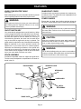
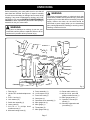
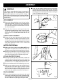
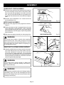
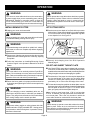
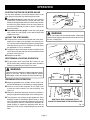
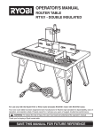
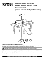
OPERATOR'S MANUAL
Model RT100 Router Table
Double Insulated
(For use only with the Ryobi R161 router)
THANK YOU FOR BUYING A RYOBI ROUTER TABLE
Your new router table has been engineered and manufactured to Ryobi's high standard for dependability, ease of operation,
and operator safety. Properly cared for, it will give you years of rugged, trouble-free performance.
CAUTION: Carefully read through this entire operator's manual before using your new router table.
Pay close attention to the Rules for Safe Operation, Warnings, and Cautions. If you use your router table properly and only
for what it is intended, you will enjoy years of safe, reliable service.
Please fill out and return the Warranty Registration Card so that we can be of future service to you.
Thank you again for buying a Ryobi router table.
SAVE THIS MANUAL FOR FUTURE REFERENCE
TABLE OF CONTENTS
■ Table of Contents and Introduction .............................................................................................................. 2
■ Rules for Safe Operation .......................................................................................................................... 3-4
■ Symbols ....................................................................................................................................................... 5
■ Features ....................................................................................................................................................... 6
■ Unpacking .................................................................................................................................................... 7
■ Assembly ................................................................................................................................................... 8-9
■ Operation .............................................................................................................................................. 10-11
■ Maintenance ............................................................................................................................................... 12
■ Notes .......................................................................................................................................................... 13
■ Parts Ordering / Service ............................................................................................................................. 14
INTRODUCTION
Your router table has many features for making router
operations more pleasant and enjoyable. Safety,
performance, and dependability have been given top
priority in the design of this router table making it easy to
maintain and operate.
CAUTION:
Carefully read through this entire Operator's Manual
and the entire R161 Operator’s Manual before using
your new router table. Pay close attention to the Rules
for Safe Operation and all Safety Alert Symbols including
Danger, Warning, and Caution. If you use your router
table properly and only for what it is intended, you will
enjoy years of safe, reliable service.
SPECIFICATIONS
Table Dimensions
12 in. x 24 in. x 1-1/8 in.
Table Footprint
16 in. x 24 in.
Dust Hookup
2-1/4 in.
Fence Width
16 in.
Maximum Stock Height
2-3/4 in.
Maximum Cutter Diameter
2-3/8 in.
Table Height
12 in.
Recommended Working Height (approximately)
37 in.
Miter Slot
3/8 in. x 3/4 in.
Maximum Stock Removal
1/8 in.
Maximum Incremental Removal per Pass
1/32 in.
WARNING:
WEAR YOUR
SAFETY
GLASSES
FORESIGHT IS BETTER
THAN NO SIGHT
The operation of any router can result in foreign objects being thrown into your eyes, which can
result in severe eye damage. Before beginning power tool operation, always wear safety goggles
or safety glasses with side shields and a full face shield when needed. We recommend Wide
Vision Safety Mask for use over eyeglasses or standard safety glasses with side shields. Always
wear eye protection which is marked to comply with ANSI Z87.1.
Page 2
RULES FOR SAFE OPERATION
READ ALL INSTRUCTIONS
Know your power tool. Safe operation of this power tool
requires that you read and understand this operator’s
manual, the Operator’s Manual for the R161 router and
all labels affixed to the tool. Learn the applications and
limitations as well as the potential hazards.
WARNING:
Do not connect your router or router table to a power
source until you have assembled and adjusted the
router table as described in this manual and have read
and understood all precautions and operating instructions in the manual and printed on the tool.
Protect your lungs. Wear a face or dust mask if the cutting operation is dusty.
Protect your hearing. Wear hearing protection during
extended periods of operation.
Secure the work. Use clamps or a vise to hold the work
when practical. It’s safer than using your hand and frees
both hands to operate the tool.
Do not overreach. Keep proper footing and balance at
all times.
Maintain the tool with care. Keep cutters sharp and clean
for the best and safest performance. Follow instructions
for lubricating and changing accessories.
Disconnect power tools before servicing or before
changing accessories such as blades, bits and cutters.
WARNING:
Reduce the risk of unintentional starting. Make sure
When using electric tools, basic safety precautions
should always be followed to reduce the risk of fire,
electric shock, and personal injury. Use common
sense. Some of these basic safety precautions include
the following:
Always keep all guards in place and in good working order.
Remove adjusting keys and wrenches. Get in the habit
switch is in the OFF position before plugging in the tool.
Use only the manufacturer’s recommended accessories. Consult this operator’s manual for recommended accessories. Using improper accessories may cause risk of
injury.
Never stand on tool. Serious injury could occur if the
tool is tipped or if the cutter is unintentionally contacted.
Periodically check for worn or damaged parts. Check
for alignment of moving parts, binding of moving parts,
breakage of parts, loose mounting brackets, and any other
conditions that may affect operation. A guard or any other
part that is damaged should be properly repaired or replaced. Before the tool is used again, make sure that the
repaired or replaced part is operating properly and performing its intended function.
of checking to see that hex keys and adjusting wrenches
are removed from the tool before turning it on.
Keep the work area clean. Cluttered work areas and
work benches invite accidents.
Do not use in dangerous environments. Do not use
power tools near gasoline or other flammable liquids, in
damp or wet locations, or expose them to rain. Keep the
work area well lighted.
Direction of feed. Feed work into a blade or cutter against
Keep children away from power tools. All visitors should
Never leave tool running unattended. Turn the power
be kept at a safe distance from the work area.
Make the workshop child-proof with padlocks and master switches or by removing starter keys.
Do not force the tool. It will do the job better and safer at
the rate for which it was designed.
Use the right tool. Do not force the tool or attachment to
the direction of rotation of the blade or cutter only.
off. Do not leave tool until it comes to a complete stop.
Do not abuse cord. Never yank the cord to disconnect it from the receptacle. Keep the cord from heat,
oil, and sharp edges.
Keep cutters clean and sharp. Sharp cutters minimize
stalling. Dirty and dull cutters may cause misalignment of
the material and possible operator injury.
do a job for which it was not designed.
Wear proper apparel. Do not wear loose clothing, gloves,
Keep hands away from cutting area. Keep hands away
neckties, rings, bracelets, or other jewelry that could get
caught in moving parts. Nonslip footwear is recommended.
Wear protective covering over long hair.
from the cutter. Do not reach underneath table or in the
cutting path with your hands or fingers at any time while
tool is connected to power source.
Always wear safety glasses with side shields. Every-
Firmly clamp or bolt your router table to a workbench
day eyeglasses have only impact resistant lenses; they
are not safety glasses.
Page 3
so the router table surface is at approximately hip height.
RULES FOR SAFE OPERATION
Keep tool dry, clean, and free from oil and grease.
WARNING:
Always use a clean cloth when cleaning. Never use brake
fluids, gasoline, petroleum-based products, or any solvents
to clean tool.
Some dust created by power sanding, sawing, grinding,
drilling, and other construction activities contains
chemicals known to cause cancer, birth defects or
other reproductive harm. Some examples of these
chemicals are:
Stay alert. Never operate a power tool when tired or
while under the influence of drugs, alcohol or medication.
lead from lead-based paints,
crystalline silica from bricks and cement and other
Do not use tool if switch does not turn it on and off.
Have defective switches replaced by an authorized service center.
masonry products, and
Always turn switch off before disconnecting it to avoid
chromium from chemically-treated lumber.
accidental starting.
Your risk from these exposures varies, depending on
how often you do this type of work. To reduce your
exposure to these chemicals, work in a well ventilated
area, and work with approved safety equipment, such
as those dust masks that are specially designed to filter
out microscopic particles.
All repairs, whether electrical or mechanical, should
be made at a Ryobi Authorized Service Center. Use only
Ryobi identical replacement parts.
Save these instructions. Refer to them frequently and
use to instruct other users. If you loan someone this tool,
loan them these instructions also.
SPECIFIC SAFETY RULES FOR THE RT100 ROUTER TABLE
For your own safety, read this RT100 Operator’s Manual
and the R161 Operator’s Manual before operating the
router or router table.
Feed workpiece against rotation of cutter.
Always use guard/dust cover.
Do not use awkward hand positions.
Keep fingers away from revolving cutter - use fixtures
when necessary.
When using the router on the router table, the router must
be plugged into the on-board switch outlet.
Look for this symbol to point out important safety precautions.
It means attention!!! Your safety is involved.
SAVE THESE INSTRUCTIONS
Page 4
SYMBOLS
The purpose of safety symbols is to attract your attention to possible dangers. The safety symbols, and the
explanations with them, deserve your careful attention and understanding. The safety warnings do not by themselves
eliminate any danger. The instructions or warnings they give are not substitutes for proper accident prevention
measures.
SYMBOL
MEANING
SAFETY ALERT SYMBOL: Indicates danger, warning, or caution. May be used in conjunction with
other symbols or pictographs.
DANGER: Failure to obey a safety warning will result in serious injury to yourself or to others. Always
follow the safety precautions to reduce the risk of fire, electric shock and personal injury.
WARNING: Failure to obey a safety warning can result in serious injury to yourself or to others.
Always follow the safety precautions to reduce the risk of fire, electric shock and personal injury.
CAUTION: Failure to obey a safety warning may result in property damage or personal injury to
yourself or to others. Always follow the safety precautions to reduce the risk of fire, electric shock and
personal injury.
NOTE:
Advises you of information or instructions vital to the operation or maintenance of the equipment.
EXTENSION CORD
When using a power tool at a considerable distance from a
power source, be sure to use an extension cord that has the
capacity to handle the current the tool will draw. An undersized cord will cause a drop in line voltage, resulting in overheating and loss of power. Use the chart to determine the
minimum wire size required in an extension cord. Only round
jacketed cords listed by Underwriter’s Lab (UL) should be
used.
Length of Extension Cord
Wire Size (A.W.G.)
Up to 50 feet
14
When working with a tool outdoors, use an extension cord
that is designed for outside use. This is indicated by the letters "WA" on the cord's jacket.
Before using any extension cord, inspect it for loose or exposed wires and cut or worn insulation.
WARNING:
The double insulated system is intended to protect the
user from shock resulting from a break in the tool's
internal wiring. Observe all normal safety precautions
related to avoiding electrical shock.
DOUBLE INSULATION
Your Ryobi power tool is double insulated. This means you
are separated from the tool’s electrical system by two complete sets of electrical insulation. This extra layer of insulation is intended to protect the user from electrical shock
due to a break in the wiring insulation. All exposed metal
parts are isolated from the internal metal motor components
with protecting insulation. Double insulated tools do not need
to be grounded.
SAFETY AND INTERNATIONAL SYMBOLS
This operator’s manual describes safety and international symbols and pictographs that may appear on this product.
Read the operator’s manual for complete safety, assembly, operating and maintenance, and repair information.
MEANING
Do not expose to rain or use in wet locations
Page 5
FEATURES
KNOW YOUR ROUTER TABLE
GUARD/DUST COVER
See Figure 1.
Before attempting to use your router table, familiarize yourself
with all operating features and safety requirements.
Provides a barrier to protect the operator from careless contact with the cutter. The guard/dust cover is adjustable for all
types of cuts and materials.
LOWER GUARDS
WARNING:
If any parts are missing do not use your router table until
the missing parts are replaced. Failure to do so could
result in possible serious injury.
Ensures that your hand, loose clothing, and other objects do
not come in contact with the cutter or collet during operation.
ON/OFF SWITCH KEY
Your router table is equipped with an on/off switch key. When
router is plugged into switch outlet and switch key is removed,
the switch key prevents the router from being turned on. The
key must be in place to turn the switch on. If the key is
removed during operation, the router can be turned off but
may not be turned on again until the key is replaced. The
switch outlet is located on the rear of the switch box assembly.
Note: As explained in your router operator’s manual, the
spindle lock on your router must be in unlocked position.
Otherwise, the interlocking mechanism of the spindle lock
will not let your router turn on. Also the lock-on button in the
router switch must be engaged in order for the on/off switch
key in your router table to activate your router.
FENCE ASSEMBLY
WARNING:
The lower guards must be securely in place before using
the router table. Failure to do so could result in serious
personal injury.
CAUTION:
Keep the cord away from the router table surface and
position the cord so that it will not be caught on lumber,
tools, or other objects during routing.
WARNING:
Do not allow familiarity with your router or router table to
make you careless. Remember that a careless fraction of
a second is sufficient to inflict severe injury.
Provides an adjustable surface to support and guide work.
The fence may be adjusted to compensate for the stock reduced in the cut.
FENCE ASSEMBLY
GUARD/DUST COVER
MITER GAUGE
TABLE SURFACE
LOWER GUARDS
SWITCH
BOX ASSEMBLY
TABLE LEGS
THROAT PLATES
Fig. 1
Page 6
UNPACKING
Before assembling your router table check to see that all
parts listed are included. See Figure 2. Inspect it carefully
to make sure no breakage or damage has occurred during
shipping. If any parts are damaged or missing, call 1-800525-2579 for your nearest RYOBI AUTHORIZED SERVICE
CENTER to obtain replacement parts before attempting to
assemble or use your router table.
WARNING:
WARNING:
To prevent accidental starting or electrical shock that
could cause possible serious personal injury, assemble
all parts to your router table before connecting it to power
supply. Neither the router nor the table should be
connected to power supply when you are assembling
parts, making adjustments, installing or removing cutters,
cleaning, or when not in use.
If any parts are damaged or missing, do not use your
router table until the parts are replaced. Failure to do so
could result in possible serious personal injury.
5
13
18
11
7
16
10
4
6
1
8
2
17
19
20
3
14
15
9
12
1. Table leg (4)
2. 1/4-20 x 1/2 in. socket head cap screw
(22)
3. 3/16 in. hex key (1)
4. Lock washer (16)
5. Switch box assembly (1)
6. Lower guard (2)
7. 5/16-18 x 1 in. phillips head
machine screw (3)
8. #6 thread cutting screw (2)
9.
10.
11.
12.
13.
14.
15.
16.
Fig. 2
Fence assembly (1)
1/4-20 square nut (2)
Fence lock knob (2)
Guard post (1)
Guard/dust cover assembly (1)
Miter gauge bar (1)
Miter gauge (1)
Throat plate (5)
17. Miter gauge knob (1)
Page 7
18. Router table surface (1)
19. #6-32 x 5/8 in. pan head
phillips machine screw (1)
20. Miter gauge pointer (1)
21. Operator’s manual (not
shown) (1)
22. Warranty registration card
(not shown) (1)
ASSEMBLY
WARNING:
Locate the two square nuts and two fence lock knobs.
Your router or router table should never be connected to
power supply when you are assembling parts, making
adjustments, installing or removing cutters, cleaning, or
when not in use. Disconnecting your router and router table
will prevent accidental starting that could cause serious
personal injury.
Position a square nut inside the channel located underneath
the table. Insert the lock knob through the hole in the fence
assembly and screw it into the square nut below. See Figures
7a and 7b. Repeat for the other side.
LEG ASSEMBLY
Place router table upside down on a flat, level surface,
so that the front edge is closest to you. Position legs as
shown in Figure 3. With the router table upside down,
the leg with the rectangular cutout should be in the front
left corner of the table.
Align the four holes in each leg with the four
Fig. 3
corresponding threaded holes in each corner of the table.
Use the hex wrench provided to secure each leg with
four 1/4-20 x 1/2 in. socket head screws and four lock
washers.
LOWER GUARD ASSEMBLY
Locate the two gray lower guards. Position them
around the throat of the table so that the three holes
of each guard line up with the three threaded holes in
the table. Use the hex wrench provided to secure each
lower guard with three 1/4-20 x 1/2 in. socket head
screws. See Figure 4.
Fig. 4
SWITCH BOX ASSEMBLY
Hold the switch box so that the words ON and OFF on the
toggle switch are upside down. Carefully insert switch box
through the cutout in the left front leg as shown in Figure 5.
Align the two small holes in the mounting tabs with the
two small holes in the leg. Using a #2 Phillips screwdriver, securely tighten each #6 thread cutting screw.
ATTACH ROUTER TO TABLE
Carefully turn table right side up and check to make sure
it rests on all four legs and does not rock. Locate the
three large holes surrounding the throat of the table and
the three 5/16-18 x 1 in. phillips head machine screws.
Fig. 5
Remove the subbase screws and subbase from your router.
Hold the router upside down so that the Ryobi label is
facing the front of the table. Align the holes in the table
with the holes in the router. Holding the router with one
hand, use the other hand to securely tighten each of the
three screws with a phillips screwdriver. See Figure 6.
FENCE ASSEMBLY
Turn the fence assembly over and locate the four small
circular tabs. Position the fence on the router table so that
the two tabs on the left engage the left channel of the table
and the two tabs on the right engage the right channel.
Page 8
Fig. 6
ASSEMBLY
GUARD/DUST COVER ASSEMBLY
Securely screw guard post into threaded hole located on
the fence assembly. Loosen knob on clear plastic guard/
dust cover and slide guard/dust cover down over guard
post. See Figures 8a and 8b. Make sure guard/dust cover
is centered over the throat of the router table and retighten
knob.
If desired, insert a standard 2-1/4 in. vacuum hose in the
top of guard/dust cover.
VIEW FROM ABOVE TABLE
Fig. 7a
MITER GAUGE ASSEMBLY
Assemble miter gauge and miter gauge bar as shown in
Figure 9.
Position the pointer so that it is perpendicular to the scale
on the miter gauge. Locate the #6-32 x 5/8 in. pan head
screw and feed it through the hole in the pointer and into
the threaded hole in the miter gauge. Tighten using a phillips
head screwdriver.
Slide entire miter gauge assembly into miter gauge track.
VIEW FROM BELOW TABLE
Fig. 7b
WARNING:
Do not wear loose clothing or jewelry when operating
table-mounted router. They could get caught in moving
parts causing serious injury. Keep head away from router
and routing area. Hair could be drawn into spinning cutter causing serious injury.
MOUNTING TO A STABLE WORK SURFACE
Using the predrilled holes in the legs, mount the four legs of
Fig. 8a
Fig. 8b
your router table securely on a sturdy surface such as a
work stand, workbench or counter top. If your router table
is to be used in a portable application, it is recommended
that you fasten it permanently to a mounting board that can
be easily clamped to a workbench. Position the router table
surface at approximately hip height.
WARNING:
All four legs must be securely bolted to a stable work
surface. Failure to heed this warning could result in
serious personal injury.
WARNING:
Check extension cords before each use. If damaged, replace
immediately. Never use tool with a damaged cord since
touching the damaged area could cause electrical shock,
resulting in serious injury.
Page 9
Fig. 9
OPERATION
WARNING:
WARNING:
Your router or router table should never be connected to
a power supply when you are assembling parts, making
adjustments, installing or removing cutters, or when not
in use. Disconnecting your router and router table will
prevent accidental starting that could cause serious injury.
INSTALL/REMOVE CUTTER
Unplug your router and router table.
Never operate the router table unless both lower guards
are securely in place. Failure to do so could allow loose
clothing, cords and hands to come in contact with the
spindle while in operation and could result in serious personal injury.
SET CUTTING DEPTH
Set the cutter at zero depth of cut (flush with top or router
table surface). Rotate depth indicator ring to desired depth
of cut on the scale, then turn depth adjustment ring back
to zero depth of cut. See Figure 10.
WARNING:
Failure to unplug your router and router table could result
in accidental starting causing serious injury.
WARNING:
To prevent damage to the spindle or spindle lock, always
allow motor to come to a complete stop before engaging
spindle lock.
Remove two of the hex cap screws securing the rear lower
guard to the table. Rotate guard out of the way, exposing
the spindle.
Follow the instructions on Installing/Removing Cutters
found on Page 8 in the Operator’s Manual for the R161
Router.
WARNING:
This router table is to be used only with the Ryobi R161
Router. Do not attempt to use any other router with this
table. Failure to heed this warning could result in improper
operation of the tool and serious personal injury.
Fig. 10
Securely lock clamping lever. See R161 Operator’s
Manual page 9.
SELECT AND INSERT THROAT PLATE
Your Ryobi RT100 router table is shipped with an assortment of five circular throat plates. The throat plate provides
a stable surface around the cutter and prevents objects from
falling through the throat and damaging the spindle.
The selection of the proper size throat plate depends on
the size and shape of the cutter you are using. When
inserted, the throat plate opening should be within approximately 1/4 in. of the outer most edge of the cutter.
Return the lower guard to its proper position and secure
by inserting and tightening the two hex screws previously
removed.
WARNING:
If you are changing a cutter immediately after use, be
careful not to touch the cutter or collet with your hands or
fingers. They will get burned because of the heat buildup
from cutting. Always use the wrench provided.
To insert the throat plate, position the throat plate over the
throat opening in the router table and snap throat plate down
and into place as shown in Figure 11. To remove throat
plate, pull gently until the throat plate snaps out.
Note: If using a cutter larger than 1-7/8 in. but less than
2-3/8 in. in diameter you may operate the router table without a throat plate. This is the only situation in which the
router table should be used without the throat plate.
WARNING:
WARNING:
Always wear safety goggles or safety glasses with side
shields marked to comply with ANSI Z87.1 during power
tool operation or when blowing dust. If operation is dusty,
also wear a dust mask.
Page 10
Never attempt to operate router table without the throat
plate in place. Failure to do so could result in the workpiece jamming or objects falling into rotating spindle which
could cause serious personal injury.
OPERATION
POSITION THE FENCE OR MITER GAUGE
For any router operation, you will use either the fence or the
miter gauge to help guide your work through the cutter.
To position the fence: Loosen the fence lock knobs by
turning them counterclockwise. Loosen the fence lock
knobs just enough so that the fence moves freely. Position
the fence the proper distance from the cutter based on
the amount of material you plan to remove. Tighten the
fence lock knobs.
Fig. 11
To position the miter gauge: Loosen the miter gauge
knob, rotate the miter gauge to the desired angle and
retighten the knob.
ADJUST THE STEP RISERS
The step risers, located on the outfeed side of the fence,
WARNING:
Do not use cutters with undersized shanks. Undersized
shanks will not tighten properly and could be thrown from
the tool, causing injury.
enable you to support your workpiece as it exits the cutter. The step risers will provide support for routing operations that remove up to 1/8 in. of material. The step risers
are adjustable in 1/32 in. increments.
To adjust the step risers loosen the two knob bolts on the
rear of the fence and push the riser forward and toward
the throat. See Figure 12.
Retighten knob bolts.
PERFORMING A ROUTING OPERATION
For the proper use of your Ryobi R161 router on your
RT100 router table, carefully read the entire Operator’s
Manual included with your Ryobi R161 router.
Fig. 12
WARNING:
Direction of feed for workpiece is always against the sharp
edges of the cutter. Failure to feed workpiece against
sharp edges of cutter can result in serious personal injury.
PREPARING FOR OPERATION
Adjust the guard/dust cover so that it will not come in contact with the workpiece or cutter during a cutting operation.
Direction of feed of the workpiece is from right to left
or with the cutter located in the fence opening. See
Figure 13.
Direction of feed must always be so that the workpiece is
being fed against the sharp edges of the rotating cutter.
The workpiece must always be tight against the fence
assembly, unless a ball-bearing piloted cutter is being
used. The infeed fence should be adjusted to support the
uncut workpiece while the outfeed fence should be adjusted properly to support the workpiece after the cut
passes the router cutter, compensating for the removed
stock.
Page 11
DIRECTION OF FEED IS FROM RIGHT TO LEFT
AGAINST THE SHARP EDGES OF THE ROTATING CUTTER.
Fig. 13
MAINTENANCE
GENERAL MAINTENANCE
Avoid using solvents when cleaning plastic parts. Most
WARNING:
When servicing, use only identical Ryobi replacement
parts. Use of any other parts may create a hazard or cause
product damage.
plastics are susceptible to damage from various types of
commercial solvents and may be damaged by their use.
Use clean cloths to remove dirt, carbon dust, etc.
Periodically check all clamps, nuts, bolts and screws for
tightness and condition. Make sure that the throat plate,
guard/dust cover assembly and lower guards are properly positioned and securely attached.
WARNING:
Always begin any maintenance procedure by disconnecting the router and router table from the power supply to
avoid risk of serious personal injury
WARNING:
Do not at any time let brake fluids, gasoline, petroleumbased products, penetrating oils, etc. come in contact with
plastic parts. They contain chemicals that can damage,
weaken, or destroy plastic.
IMPORTANT
Servicing of a tool with double insulation requires extreme
care and knowledge of the system and should be performed
only by a qualified service technician. For service we suggest
you return the tool to your nearest RYOBI AUTHORIZED
SERVICE CENTER for repair. When servicing use only
identical Ryobi replacement parts.
To reduce the risk of electric shock, this equipment has a
polarized plug (one blade is wider than the other). This plug
will fit in a polarized outlet only one way. If the plug does not
fit fully in the outlet, reverse the plug. If it still does not fit,
contact a qualified electrician to install the proper outlet. Do
not change the plug in any way.
Page 12
NOTES
Page 13
OPERATOR'S MANUAL
Model RT100 Router Table
Double Insulated
(For use only with the Ryobi R161 router)
EXTENSION CORD CAUTION
Make sure your extension cord is in good condition. When using a power tool at a considerable distance from a power source,
be sure to use an extension cord that has the capacity to handle
the current the tool will draw. An undersized cord will cause a
drop in line voltage, resulting in overheating and loss of power.
Use the chart to determine the minimum wire size required in
an extension cord. Only round jacketed cords should be used.
When working with a tool outdoors, use an extension cord that
is designed for outside use. This is indicated by the letters "WA"
on the cord's jacket.
Before using any extension cord, inspect it for loose or exposed
wires and cut or worn insulation.
**Ampere rating
(on tool data plate)
0-2.0
Cord Length
2.1-3.4
3.5-5.0
5.1-7.0
7.1-12.0 12.1-16.0
Wire Size (A.W.G.)
25'
16
16
16
16
14
14
50'
16
16
16
14
14
12
100'
16
16
14
12
10
—
CAUTION:
Keep the extension cord clear of the working area. Position
the cord so that it will not get caught on workpiece, tools, or
other obstructions while you are working with a power tool.
**Used on 12 gauge - 20 amp circuit.
• SERVICE
Now that you have purchased your tool, should a need ever exist for repair parts or service,
simply contact your nearest Ryobi Authorized Service Center. Be sure to provide all
pertinent facts when you call or visit. Please call 1-800-525-2579 for your nearest Ryobi
Authorized Service Center. You can also check our web site at www.ryobitools.com for a
complete list of Authorized Service Centers.
• MODEL NO. AND SERIAL NO.
The model number and serial number of this tool will be found on a plate attached to the
motor housing.
Please record the serial number in the space provided below.
•
MODEL NUMBER
•
SERIAL NUMBER
RT100
Ryobi Technologies Inc.
972000-943
1428 Pearman Dairy Road
Anderson, SC 29625
Post Office Box 1207 Anderson, SC 29622-1207
Phone 1-800-525-2579
www.ryobitools.com