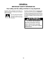
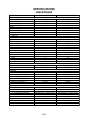
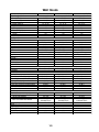
1
KAC-30
TECHNICAL EDUCATION
36″ & 48″ ISLAND
AND WALL CANOPY
RANGE HOODS
JOB AID 4317332
FORWARD
This Job Aid, KitchenAid “36″ and 48″ Island And Wall Canopy Range Hoods,” (Part No. 4317332),
provides the technician with information on servicing the Island And Wall Canopy Range Hoods.
It is to be used as a training Job Aid and Service Manual. For specific information on the model being
serviced, refer to the “Use and Care Guide” provided with the hood.
The Wiring Diagrams used in this Job Aid are typical and should be used for training purposes only.
Always use the Wiring Diagram supplied with the product when servicing the unit.
GOALS AND OBJECTIVES
The goal of this Job Aid is to provide detailed information that will enable the service technician to
properly diagnose malfunctions and repair the KitchenAid Island And Wall Canopy Range Hoods.
The objectives of this Job Aid are to:
• Understand and follow proper safety precautions.
• Successfully troubleshoot and diagnose malfunctions.
• Successfully perform necessary repairs.
• Successfully return the range hood to its proper operational status.
WHIRLPOOL CORPORATION assumes no responsibility for any repairs made
on our products by anyone other than Authorized Service Technicians.
Copyright © 2001, Whirlpool Corporation, Benton Harbor, MI 49022
- ii -
TABLE OF CONTENTS
Page
GENERAL ............................................................................................................................... 1-1
Important Safety Information ............................................................................................. 1-1
KitchenAid Model & Serial Number Designations .............................................................. 1-2
Model & Serial Number Label Location ............................................................................. 1-3
Specifications ..................................................................................................................... 1-4
KitchenAid Range Hood Warranty ..................................................................................... 1-7
COMPONENT ACCESS ......................................................................................................... 2-1
Wall Hood Component Locations ...................................................................................... 2-1
Removing A Slide Switch, The Indicator Lamp, & The Blower Motor ................................ 2-2
Removing A Halogen Lamp Socket ................................................................................... 2-5
Island Hood Component Locations .................................................................................... 2-6
Removing The Ballast Transformer ................................................................................... 2-7
Removing The Control Board ............................................................................................ 2-8
Removing The Blower Motor ........................................................................................... 2-10
COMPONENT TESTING ........................................................................................................ 3-1
Blower Motor ...................................................................................................................... 3-1
Ballast Transformer ........................................................................................................... 3-1
2- & 3-Position Slide Switches ........................................................................................... 3-2
Speed (Variable) Control ................................................................................................... 3-2
WIRING DIAGRAMS .............................................................................................................. 4-1
Island Hood ........................................................................................................................ 4-1
Wall Hood .......................................................................................................................... 4-2
- iii -
— NOTES —
- iv -
GENERAL
IMPORTANT SAFETY INFORMATION
Your safety and the safety of others is very important.
All safety messages will be preceded by the
safety alert symbol and the word “WARNING.”
All safety messages will identify the hazard, tell
you how to reduce the chance of injury, and tell
you what can happen if the instructions are not
followed.
Important safety messages have been provided in this Job Aid. Always read and obey all
safety messages.
This is the safety alert symbol.
This symbol alerts you to hazards that can kill or hurt you
and others.
WARNING
ELECTRICAL SHOCK HAZARD
Disconnect power before servicing.
Replace all panels before operating.
Failure to do so could result in death or
electrical shock.
1-1
KITCHENAID MODEL & SERIAL NUMBER DESIGNATIONS
MODEL NUMBER
MODEL NUMBER
INTERNATIONAL SALES IND.
OR MARKETING CHANNEL
IF PRESENT
K
WC
U
38
0
J
SS
0
PRODUCT GROUP
K = KITCHENAID BRAND
PRODUCT IDENTIFICATION
IC = ISLAND HOOD
IV = ISLAND VENT
IR = ISLAND RETRACTABLE
WV = WALL VENT
PI = POWER INTERIOR
PE = POWER EXTERIOR
SV = SIDE VENT
WC = WALL CANOPY
MERCHANDISING SCHEME
D = DOWNDRAFT
U = UPDRAFT
CAPACITY / SIZE / SERIES / CONFIGURATION
1ST POSITION
2ND POSITION
0 = 30″ WIDE
0 = SIDE DOWNDRAFT
5 = 500 CFM
1 = STANDARD UPDRAFT
6 = 36″ WIDE
2 = SLIDE-OUT UPDRAFT
8 = 48″ WIDE
3 = CANOPY
9 = 900 CFM
8 = DOWNDRAFT
FEATURES
0 = STANDARD
1 = INTERIOR POWER
2 = EXTERNAL POWER
5 = ELECTRONIC CONTROLS
YEAR OF INTRODUCTION
H = 1999
J = 2000
K = 2001
COLOR CODE
WT = WHITE
BT = BISCUIT
SS = BRUSHED STAINLESS STEEL
ENGINEERING CHANGE (0, 1, 2, ETC.)
SERIAL NUMBER
SERIAL NUMBER
MANUFACTURING SITE
YEAR OF PRODUCTION
J = 1999, K = 2000, L = 2001, M = 2002
WEEK OF PRODUCTION
46TH WEEK
PRODUCT SEQUENCE NUMBER
FJ
J
46
1-2
02453
MODEL & SERIAL NUMBER LABEL LOCATION
The Model/Serial Number label locations are shown below.
Model & Serial Number Location
(Island Range Hood)
Model & Serial Number Location
(Wall Range Hood)
1-3
SPECIFICATIONS
Island Hoods
Model Number
Dimensions/Specifications
Overall Width (in)
Overall Depth (in)
Canopy Height (in)
Chimney Height (in)
Weight
Net Weight (lbs)
Shipping Weight (lbs)
Ratings
120v AC
Circuit Amps
Exterior
Hood Exterior
Type/Configuration
Size (Inches)
Color
Grease Filters
CFM
Sones
Light
Brand Logo Location
Controls
On/Off
Variable Speed
Auto Off
Interior
Ducting
Dimension
Accessories
Backsplash
Backsplash Kit Part/Description
Ductless Operation Kit Part/Description
Chimney Extension Kit
Wire Rack Kit Part/Description
Wire Rack Hanger Kit Part/Description
Utensil Bar-15 Inch Sides Kit
Utensil Bar-Back
Miscellaneous
Product Literature
Installation Instructions Part/Comment
Job Aid Part/Comment
Use & Care Guide Part/Comment
Wiring Diagram Part/Comment
Other
Agency Approvals
Warranty
Full (Months)
Power System Motor
KICU265H
SS, WT, BT
KICU285H
SS, WT, BT
35 3/8"
23 5/8"
10 1/4"
24 5/8" to 34 3/4"
47 1/4"
23 5/8"
10 1/4"
24 5/8" to 34 3/4"
77
82
84
90
Yes
15 AMP
Yes
15 AMP
Canopy-Updraft
36 Inches
Stainless
3 Heavy Duty (DW Safe)
600
6.5
2 Fluorescent Bulbs
KitchenAid
Canopy-Updraft
48 Inches
Stainless
3 Heavy Duty (DW Safe)
600
6.5
2 Fluorescent Bulbs
KitchenAid
Yes
Yes
No
Yes
Yes
No
Convertible with kit
3 1/4" x 10"
Convertible with kit
3 1/4" x 10"
4378625/Stainless
4378625/Stainless
4378619
4378619
4360369
4317332
4360369/English; 4360370/French
In Use and Care Guide
4360369
4317332
4360369/English; 4360370/French
In Use and Care Guide
UL,CUL
UL,CUL
12
48 Mo
12
48 Mo
1-4
Wall Hoods
Model Number
Dimensions/Specifications
Overall Width (in)
Overall Depth (in)
Canopy Height (in)
Chimney Height (in)
Weight
Net Weight (lbs)
Shipping Weight (lbs)
Ratings
120v AC
Circuit Amps
Exterior
Hood Exterior
Type/Configuration
Size (Inches)
Color
Grease Filters
CFM
Sones
Light
Brand Logo Location
Controls
On/Off
Variable Speed
Auto Off
Interior
Ducting
Dimension
Accessories
Backsplash
Backsplash Kit Part/Description
Ductless Operation Kit Part/Description
Chimney Extension Kit
Wire Rack Kit Part/Description
Wire Rack Hanger Kit Part/Description
Utensil Bar-15 Inch Sides Kit
Utensil Bar-Back
Miscellaneous
Product Literature
Installation Instructions Part/Comment
Job Aid Part/Comment
Use & Care Guide Part/Comment
Wiring Diagram Part/Comment
Other
Agency Approvals
Warranty
Full (Months)
Power System Motor
KWCU205H SS, WT, BT KWCU265H
SS, WT, BT
KWCU285H SS, WT, BT
29 7/8"
19 1/4"
9 1/2"
23" to 42"
35 3/8"
19 1/4"
9 1/2"
23" to 42"
47 1/4"
19 1/4"
9 1/2"
23" to 42"
45
49
52
57
59
65
Yes
15 AMP
Yes
15 AMP
Yes
15 AMP
Wall-Updraft
30 Inches
Stainless
2 Heavy Duty (DW Safe)
600
6.5
1 Fluorescent Bulb
KitchenAid
Wall-Updraft
36 Inches
Stainless
3 Heavy Duty (DW Safe)
600
6.5
1 Fluorescent Bulb
KitchenAid
Wall-Updraft
48 Inches
Stainless
3 Heavy Duty (DW Safe)
600
6.5
1 Fluorescent Bulb
KitchenAid
Yes
Yes
No
Yes
Yes
No
Yes
Yes
No
Convertible with kit
3 1/4" x 10"
Convertible with kit
3 1/4" x 10"
Convertible with kit
3 1/4" x 10"
8171295/Stainless
4378621/Stainless
N/A
8171297
4378617
4378619
8171299
4378615/Stainless
4378621/Stainless
N/A
4378616
4378617
4378619
4378618
8171296/Stainless
4378621/Stainless
N/A
8171298
4378617
4378619
4317332
4360367/English;
4360368/French
In Use & Care Guide
4317332
4360367/English;
4360368/French
In Use & Care Guide
4317332
4360367/English;
4360368/French
In Use & Care Guide
UL,CUL
UL,CUL
UL,CUL
12
48 Mo
12
48 Mo
12
48 Mo
1-5
Model Number
Size-Configuration
Feature Level/Series
Dimensions/Specifications
Exterior Dimensions
Overall Width (in)
Overall Depth (in)
Canopy Height (in)
Chimney Height (in)
Other Dimensions
Net Weight (lbs)
Shipping Weight (lbs)
Ratings
Electric Voltage/Phase/Frequency (Hz)
120v AC
Circuit Amps
KWCU380JSS
48" - Wall Canopy
Professional Series
KWCU360JSS
36" - Wall Canopy
Professional Series
48"
25"
18"
Accessory
36"
25"
18"
Accessory
79
116
54
84
60 HZ
Yes
15
60 HZ
Yes
15
Wall-Updraft
48 Inches
Stainless
Baffle
Internal
1200
Maximum 6.5
4 Halogen Lights (12V 20 watt, Included)
No Heat Lamps
Under Canopy
3 Slide Switches
Yes
Yes
No
3
No
Wall-Updraft
36 Inches
Stainless
Baffle
Internal
600
Maximum 6.5
3 Halogen Lights (12 V 20 watt, Included)
No Heat Lamps
Under Canopy
3 Slide Switches
Yes
Yes
No
3
No
Top or Rear Vented
Rectangular 3 1/4" x 10"
Top or Rear Vented
Rectangular 3 1/4" x 10"
Optional
8284755/Stainless; telescopic, height
extends up to 39" high
Optional - 2 Choices
8284752: 48"(W) x 12"(H) or 8284754:
24"(W) x 12" to 24"(H) (Height expands
to 8' - 9' ceilings)
Optional
8284756/Stainless; telescopic, height
extends up to 39"
Optional - 2 choices
8284753: 36"(W) x 12"(H) or 8284754:
24"(W) x 12" to 24" (H) (Height expands
to 8' - 9' Ceilings)
Exterior
Hood Exterior
Type/Configuration
Size (Inches)
Color
Grease Filters
Power System
CFM
Sones
Light
Warming Lamp
Control Area
Controls
Light On/Off
Blower On/Off
Variable Speed
Number of Speeds
Auto Off
Interior
Ducting
Dimension
Accessories
Backsplash
Backsplash Kit Part/Description
Chimney Extension Kit
Chimney Extension Kit Part/Description
Comment
Miscellaneous
Product Literature
Installation Instructions Part/Comment
Use & Care Guide Part/Comment
Job Aid
Other
Agency Approvals
Warranty
Full (Months)
Power System Motor
Discharge Transition = 8284757:
Transitions from two 3 1/4" x 10" to One
10" Rnd (not for use w/chimney kit
8284754)
8284601
w/installation instructions, 8284601
4317332
8284601
w/installation instructions, 8284601
4317332
UL,CUL
UL,CUL
12
48 Mo
12
48 Mo
1-6
KITCHENAID RANGE HOOD WARRANTY
LENGTH OF
WARRANTY:
KITCHENAID
WILL PAY FOR:
KITCHENAID
WILL NOT PAY FOR:
LIMITED ONEYEAR WARRANTY
From Date of
Purchase.
Labor and any
parts of your range
hood (except light
bulbs and filters)
which are defective
in materials or
workmanship.
A. Consumable parts such as light bulbs and
filters.
B. Service calls to:
1. Correct the installation of the range hood.
2. Instruct you how to use the range hood.
3. Replace house fuses or correct house
wiring.
C. Repairs when range hood is used in other
than normal single-family household use.
D. Pickup and delivery. This product is designed to be repaired in the home.
E. Damage to the range hood resulting from
accident, misuse, fire, flood, acts of God, or
use of products not approved by KitchenAid.
KITCHENAID SHALL NOT BE LIABLE FOR INCIDENTAL OR CONSEQUENTIAL DAMAGES.
Some states do not allow the exclusion or limitation of incidental or consequential damages, so
this exclusion or limitation may not apply to you. This warranty gives you specific legal rights
and you may also have other rights which vary from state to state.
Outside the United States, a different warranty may apply. For details, please contact
your authorized KitchenAid dealer.
1-7
— NOTES —
1-8
COMPONENT ACCESS
This section instructs you on how to service each component inside the island and wall canopy
range hoods. The wall hood components and their locations are shown below. The island hood
component access begins on page 2-6.
WALL HOOD COMPONENT LOCATIONS
Halogen Lamps
Blower Motor
2-1
Slide Switches
& Indicator Lamp
REMOVING A SLIDE SWITCH,
THE INDICATOR LAMP & THE BLOWER MOTOR
4.
WARNING
Remove the three mounting screws from
the control assembly cover and remove
the cover.
ELECTRICAL SHOCK HAZARD
Disconnect power before servicing.
Replace all panels before operating.
Failure to do so could result in death or
electrical shock.
NOTE: Sharp edges may be present.
1.
2.
3.
Disconnect the electrical power to the
hood.
Remove the three filters from the hood.
Remove the two screws from the control
assembly and pull the assembly around
through the filter section to the front.
Control
Assembly Cover
Screw (1 of 3)
5.
Control
Assembly
Screws
To remove a slide switch:
a) Disconnect the wire connectors from
the switch terminals.
b) Use a small screwdriver and pry the tab
on the control housing away from the
switch, and push the switch out of the
holder. NOTE: The control assembly
wiring is shown on the next page.
3 Slide Switches
REASSEMBLY NOTE: Before you reassemble
the control assembly, make sure that:
• You route the wiring carefully so that it
does not become pinched between the
housing sections.
• All of the switch lug wire connectors are
securely over the lugs. Also check to see
that the metal contacts remain inside the
plastic holders and have not been pushed
out.
• The slide switches operate properly before securing the housing sections.
Control Housing Tab
Push Switch Out
Of Housing
2-2
To remove the indicator lamp, pull it out
of the control housing and disconnect the
wires from the two slide switch terminals.
7.
To remove the blower motor:
a) Remove the three screws from the
motor mounting brackets on both sides
of the blower motor (6 total).
b) Disconnect the wire connectors from
the slide switch terminals.
Screw
Indicator Lamp
Screw
Screw
Blower Motor
MOTOR
Continued on the next page.
White
White
Orange
Indicator
Indicator
2-3
Violet
Black
Red
Black
Black
Black
Violet
e
Whit
Indicator
Black
Control Assembly Wiring
Br
ow
n
Gr
ay
Vio
let
Blu
e
Orang
e
6.
c) Lift the cable clamp, remove the motor
cable, and remove the blower motor
from the hood.
f) Remove the four motor bracket mounting screws from the center of the motor
housing, and pull the motor and bracket
out of the housing.
g) Remove the mounting nut from each of
the blower wheels and remove the
wheels from the blower motor.
Blower Wheel Nut
Cable Clamp
Motor Bracket
Screw (1 of 4)
d) Position the blower motor on a work
surface on one of its sides.
e) Remove the five screws from the blower
motor housing side cover that is facing
up and remove the cover. NOTE: Do
not remove the plastic grille from the
cover.
Housing Side Cover
Side Cover Screw
(1 of 5)
2-4
REMOVING A HALOGEN LAMP SOCKET
4.
WARNING
ELECTRICAL SHOCK HAZARD
Disconnect power before servicing.
Replace all panels before operating.
Failure to do so could result in death or
electrical shock.
Pull the halogen lamp out of the socket clip
and remove the lamp pins from the socket.
Socket
Clip
NOTE: Sharp edges may be present.
1.
2.
Disconnect the electrical power to the
hood.
Remove the two screws from the halogen
lamp holder and pull the holder away from
the hood so the wire connectors are exposed.
Lamp Pins
5.
Remove the clip from the socket by releasing the tabs from the slots.
Halogen Lamp
Screw
Screw
Clip Tab & Slot
6.
3.
Remove the two screws from the socket
and remove the socket from the holder.
Remove the twist-on wire nuts from the
two wires and untwist the wires.
Socket
Screws
Wire Nut
Wire Nut
2-5
ISLAND HOOD COMPONENT LOCATIONS
Ballast Transformer
Ballast Transformer
Control Board Assembly
Blower Motor
2-6
REMOVING THE BALLAST TRANSFORMER
6.
WARNING
ELECTRICAL SHOCK HAZARD
Disconnect power before servicing.
Replace all panels before operating.
Failure to do so could result in death or
electrical shock.
Lamp Holder Screws
NOTE: Sharp edges may be present..
1.
2.
3.
7.
Disconnect the electrical power to the
hood.
Remove the three filters from the hood.
Remove the screw from each of the fluorescent lamp lens retainers and remove
the retainers.
8.
9.
Lens Retainers
4.
Remove the two screws from the fluorescent lamp holder and remove the holder.
Remove the wire nut from one of the
ballast transformer wires and untwist the
wire ends.
Remove the plastic tubing from the transformer wires and cut the second transformer wire near the case.
Remove the two screws from the transformer and remove the transformer.
Slide the fluorescent lamp lens to either
end of the holder and remove it from the
holder tabs.
Ballast Transformer Screws
Lens Holder Tabs
Wire Nut
Slide Lens & Lift
End To Remove
Cut 2nd Wire Here
5.
Remove the fluorescent lamp from the
sockets.
REASSEMBLY NOTE: You will have to splice
the cut ballast transformer wire, (going to the
fluorescent lamp socket), to either of the two
wires coming from the new transformer, and
secure the ends with a wire nut. Cut the wires
to the appropriate length, as necessary.
Fluorescent Lamp
2-7
REMOVING THE CONTROL BOARD
6.
WARNING
Slide the control housing out of the plastic
frame and remove the plastic pin, spring,
and housing from the frame.
ELECTRICAL SHOCK HAZARD
Disconnect power before servicing.
Replace all panels before operating.
Failure to do so could result in death or
electrical shock.
Spring & Pin
NOTE: Sharp edges may be present.
1.
2.
3.
Disconnect the electrical power to the
hood.
Remove the three filters from the hood.
Remove the two screws from the control
assembly and pull the assembly around
through the filter section to the front.
Screw
Frame
7.
Screw
Remove the housing screw from the control assembly.
Control Assembly
4.
5.
Housing
Housing Screw
Pull the two pivot pins out of the ends of
the control assembly.
Remove the two screws from the cable
clamp and remove the clamp.
8.
Cable Clamp & 2 Screws
Separate the two sections by rotating the
slide switch section away from the housing and unsnapping the two tabs from their
slots.
Tab
Pivot Pins
2-8
Tab
Slide Switch Section
9.
Remove the wires from the screw terminals on the two terminal blocks, and remove the control board from the housing.
NOTE: Make sure to connect the wires to
the same terminal locations on the new
board (see the wiring illustration).
REASSEMBLY NOTES:
• Before you reassemble the control assembly, make sure that the slide switches operate properly, and that the indicator light is in
line with the red lens, before securing the
housing sections.
• Install the spring in the control assembly as
shown below. Keep the short end of the
spring on top of the boss (molded on the
side of the switch panel). Also keep the long
end of the spring against the inside of the
frame, and the pin in the grooved track.
Control Board
Terminal Block 2
Terminal Block 1
Position Pin
In Track Here
White
Black
2 Black
Blue
Orange
2 White
2 Black
Black
White
Keep Long End Of
Spring Against
Inside Of Frame
Control Board
Place Short End
Of Spring On Top
Of Boss Here
2-9
REMOVING THE BLOWER MOTOR
5.
WARNING
6.
ELECTRICAL SHOCK HAZARD
Disconnect power before servicing.
Replace all panels before operating.
Failure to do so could result in death or
electrical shock.
Position the blower motor on a work surface on one of its sides.
Remove the five screws from the blower
motor housing side cover that is facing up
and remove the cover. NOTE: Do not
remove the plastic grille from the cover.
Housing Side Cover
NOTE: Sharp edges may be present.
1.
2.
3.
4.
Disconnect the electrical power to the
hood.
Remove the three filters from the hood.
Remove the control assembly and disconnect the wires from the control board terminal block screws (see pages 2-8 & 2-9
for the procedure).
Remove the two screws from each side of
the blower motor mounting bracket, and
remove the blower motor from the hood.
Side Cover Screw
(1 of 5)
7.
Remove the four motor bracket mounting
screws from the center of the motor housing, and pull the motor and bracket out of
the housing.
Blower Wheel Nut
Blower Motor
Motor Bracket
Screw (1 of 4)
Blower Motor Screws (2 On Each Side)
8.
2-10
Remove the mounting nut from each of the
blower wheels and remove the wheels
from the blower motor.
COMPONENT TESTING
Before testing any of the components, perform
the following checks:
• The most common cause for control failure is
corrosion on connectors. Therefore, disconnecting and reconnecting wires will be necessary throughout test procedures.
• All tests/checks should be made with a VOM
or DVM having a sensitivity of 20,000 ohmsper-volt DC, or greater.
• Check all connections before replacing components, looking for broken or loose wires,
failed terminals, or wires not pressed into
connectors far enough.
• Voltage checks must be made with all connectors attached to the boards.
• Resistance checks must be made with power
cord unplugged from outlet, and with wiring
harness or connectors disconnected.
WARNING
ELECTRICAL SHOCK HAZARD
Disconnect power before servicing.
Replace all panels before operating.
Failure to do so could result in death or
electrical shock.
BLOWER MOTOR
BALLAST TRANSFORMER
(ISLAND HOODS ONLY)
Refer to page 2-2 (wall hoods), or 2-10 (island
hoods), for the procedure for accessing the
blower motor.
1. Disconnect the electrical power to the
hood.
2. Disconnect the wires from the blower motor
terminals.
3. Set the ohmmeter to the R x 1 scale.
4. Touch the ohmmeter leads to the blue and
white motor wires. The meter should indicate between 15 and 35 Ω.
Refer to page 2-7 (island hoods), for the procedure for accessing the ballast transformer.
1. Disconnect the electrical power to the
hood.
2. Set the ohmmeter to the R x 1 scale.
3. Touch the ohmmeter leads to the ballast
transformer wire ends at the wire nut and
the fluorescent lamp socket. The meter
should indicate between 18 and 28 Ω.
3-1
WARNING
ELECTRICAL SHOCK HAZARD
Disconnect power before servicing.
Replace all panels before operating.
Failure to do so could result in death or
electrical shock.
2- & 3-POSITION SLIDE SWITCHES
2-Position
1
2
1
SPEED (VARIABLE) CONTROL
(ISLAND HOODS ONLY)
3-Position
2
3
Touch Leads To These Two Screws
(With Blue & Orange Wires)
Contacts (Pos 1)
Contacts (Pos 1)
Refer to page 2-2 (wall hoods), or 2-8 (island
hoods), for the procedure for accessing the
slide switches.
NOTE: The island hood slide switches are
soldered to the control board and have to be
tested on the board. The wall hood slide
switches have wire connectors that can be
removed for testing.
1. Disconnect the electrical power to the
hood.
2. Disconnect the wires from the switch terminals (wall hoods).
3. Set the ohmmeter to the R x 1 scale.
4. Refer to the illustration above, and touch
the ohmmeter test leads to the switch pins
that have the slider in the “contact” position (1). The meter should indicate a closed
(0 Ω) circuit.
5. With the meter leads at the same pin
locations and the slider in another position, the meter should indicate an open
(infinite) circuit.
NOTE: If the readings do not indicate as specified, replace the switch (wall hoods) or the
control board (island hoods).
Slider
Refer to page 2-8 (island hoods), for the procedure for accessing the control board.
NOTE: The island hood speed control is soldered to the control board and can be tested on
the board.
1. Disconnect the electrical power to the
hood.
2. Set the ohmmeter to the R x 10K scale.
3. Position the speed control slider all the
way to the left (see above).
4. Touch the ohmmeter test leads to the two
indicated terminal screws (with the orange
and blue wires). The meter should indicate approximately 260K Ω.
5. Leave the leads touching the two terminal
screws, and slowly push the slider all the
way to the right. The meter resistance
should gradually change from 260 KΩ to
0 Ω.
NOTE: If the readings do not indicate within
20% of those specified, replace the control
board.
3-2
WIRING DIAGRAMS
ISLAND HOOD
Slide Switches
1
0
1
0
56KΩ
Speed Control (260 KΩ)
Ballast Trans.
(18 - 28 Ω)
WH
BK
WH
WH
BK
BK
OR
BU
BK
Indicator
BK
S
BK
Ballast Trans.
(18 - 28 Ω)
Fluorescent Lamp
BK
S
BK
Fluorescent Lamp
BU
BK
BU
M
WH
BK
BK
4-1
BK
GN
Line In
120 VAC
60 Hz
WH
Blower Motor
Wiring Box
OR
BK
BU
WH
11 µF
WALL HOOD
Slide Switches
1 2 3
VI
RD
BK
GY
BR
WH
11 µF
Directional Lamps
M
GN
Blower Motor
WH
GN
BK
Wiring Box
BK
WH
OR
BU
VI
BK
Transformer
120 VAC
Line Input
4-2
PRODUCT SPECIFICATIONS
AND
WARRANTY INFORMATION SOURCES
IN THE UNITED STATES:
FOR PRODUCT SPECIFICATIONS AND WARRANTY INFORMATION CALL:
FOR WHIRLPOOL PRODUCTS: 1-800-253-1301
FOR KITCHENAID PRODUCTS: 1-800-422-1230
FOR ROPER PRODUCTS:
1-800-447-6737
FOR TECHNICAL ASSISTANCE WHILE AT THE CUSTOMER’S HOME CALL:
THE TECHNICAL ASSISTANCE LINE: 1-800-253-2870
HAVE YOUR STORE NUMBER READY TO IDENTIFY YOU AS AN
AUTHORIZED SERVICER
FOR LITERATURE ORDERS:
PHONE: 1-800-851-4605
IN CANADA:
FOR PRODUCT SPECIFICATIONS AND WARRANTY INFORMATION CALL:
1-800-461-5681
FOR TECHNICAL ASSISTANCE WHILE AT THE CUSTOMER’S HOME CALL:
THE TECHNICAL ASSISTANCE LINE: 1-800-488-4791
HAVE YOUR STORE NUMBER READY TO IDENTIFY YOU AS AN
AUTHORIZED SERVICER