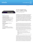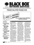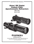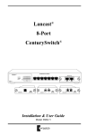
1
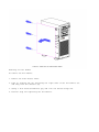
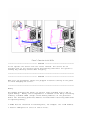
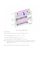
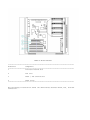
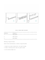
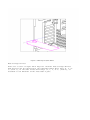
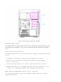
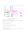
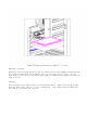
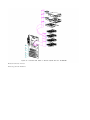
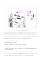
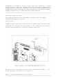
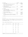
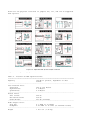
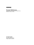
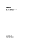
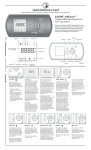
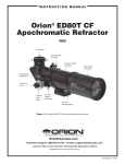
Addendum
Publication Date: October 1994
Document Name:
Addendum to the Maintenance and Service Guide ProSignia
500 Family of PC Servers (Document Number: 144257-001)
Document Number: 188389-001
This addendum only provides specific information for the Compaq ProSignia
500 Family of Servers. Refer to the Maintenance and Service Guide for
Compaq ProSignia PC Servers (144257-001) for general procedures not found
in this addendum.
o Illustrated Parts Catalog
- System Exploded View
- Spares Parts List
o Removal and Replacement Procedures
- Removing the Side Access Panel
- Removing the Air Baffle
- Memory
- Option Boards
- Mass Storage Devices
- Removable Media Storage
- Drive Installation Guidelines
- Mass Storage Devices in the Removable Media Area
- External Storage
- Cabling
- Miscellaneous Parts
- Battery Replacement
o Switch and Jumper Settings
- System Board
- SCSI Devices
o Physical and Operating Specifications
- CD-ROM Drive
Illustrated Parts Catalog
This section provides an illustrated parts breakdown and a spare parts list
for the Compaq ProSignia 500 Family of Servers.
Table 1. Spares Parts List
===========================================================================
Item
Description
Part Number
===========================================================================
CHASSIS
------1
CPU Chassis
211412-001
2
System Unit Hood
144208-001 *
3
Access Panel
144210-001 *
4
Front Bezel
211414-001 *
5
Fan Assembly
211410-001 *
6
Speaker Assembly (includes board guide)
211411-001
7
Power/Drive LED Bracket
119853-001
8
Blank Bezel, 1/2 Height
116793-001 *
9
Blank Bezel, 1/3 Height
116792-001 *
10
Blank Bezel, 1/6 Height
116791-001
11
Air Baffle
211413-001 *
12
Foot
149106-001
13
ProSignia 500 Logo
211419-001 *
14
Option Slot Cover
101144-001
15
Power Switch Cover
146799-001 *
SYSTEM COMPONENTS
----------------16
Power Supply
144206-001
BOARDS
-----17
System I/O Board
188307-001
18
90 MHz Processor Board, P54C/90, PCI
211420-001
18
120 MHz Processor Board without processor
169174-002 *
18
120 MHz Processor with heatsink
222906-001 *
19
32-Bit Fast-SCSI-2 Controller Board
142040-001 *
20
Compaq SMART SCSI Array Controller Board
142130-001 *
21
32-Bit NetFlex Controller Board
142041-001 *
22
DualSpeed Token Ring Module
142042-001 *
23
NetFlex-2 Token Ring Controller
199521-001 *
24
NetFlex-2 DualPort Token Ring Controller
142195-001 *
--------------------------------------------------------------------------Item
Description
Part Number
--------------------------------------------------------------------------MASS STORAGE
-----------25
1.2-MB Diskette Drive
112566-001
26
1.44-MB Diskette Drive with Bracket
144207-001
27
3.5 Inch Diskette Drive without Bracket
(3 Mode)
160788-201
28
Tray Load CD-ROM Drive
142223-201 *
29
2.1-GB Fast-SCSI-2 Hard Drive
142272-001
30
1.05-GB Fast-SCSI-2 Hard Drive
142039-001
31
535-MB Fast-SCSI-2 Hard Drive
137730-001
32
5.0-GB DAT Drive
142074-001 *
33
525-MB ACA Tape Drive
142073-001 *
34
1.2-GB ACA Tape Drive
199574-001 *
MEMORY
-----35
4-MB Memory Module (70 ns)
4-MB Memory Module (60 ns)
141754-001
139139-001
36
8-MB Memory Module (70 ns)
8-MB Memory Module (60 ns)
141755-001
139140-001
37
16-MB Memory Module (70 ns)
16-MB Memory Module (60 ns)
149947-001
139141-001
38
32-MB Memory Module (70 ns)
32-MB Memory Module (60 ns)
149948-001
139142-001
39
256-KB Secondary Write-Back Cache
190166-001 *
--------------------------------------------------------------------------Item
Description
Part Number
--------------------------------------------------------------------------CABLE KITS
---------40
Diskette Drive Signal Cable
143706-001 *
41
SCSI 2-Device Signal Cable with Terminator
211408-001 *
42
SCSI 7-Device Signal Cable with Terminator
211409-001 **
43
NetFlex-2 Token Ring Controller Cable
199539-001 *
KEYBOARDS/MOUSE
--------------44
Spacesaver Keyboard, U.S. English
160648-201 *
45
Spacesaver Keyboard, U.K. English
160648-203 *
46
Spacesaver Keyboard, German
160648-204 *
47
Spacesaver Keyboard, French
160648-205 *
48
Spacesaver Keyboard, Italian
160648-206 *
49
Spacesaver Keyboard, Spanish
160648-207 *
50
Spacesaver Keyboard, Danish
160648-208 *
51
Spacesaver Keyboard, Norwegian
160648-209 *
52
Spacesaver Keyboard, Swedish/Finnish
160648-210 *
53
Spacesaver Keyboard, Swiss
160648-211 *
54
Spacesaver Keyboard, French Canadian
160648-212 *
55
Spacesaver Keyboard, Portuguese
160648-213 *
56
Spacesaver Keyboard, Turkish
160648-214 *
57
Spacesaver Keyboard, Greek
160648-215 *
58
Spacesaver Keyboard, Latin American
160648-216 *
---------------------------------------------------------------------------
Item
Description
Part Number
--------------------------------------------------------------------------59
Spacesaver Keyboard, Arabic
160648-236 *
60
Spacesaver Keyboard, Belgian
160648-218 *
61
Spacesaver Keyboard, Japanese
160648-219 *
62
Spacesaver Keyboard, BHCSY **
160648-220 *
63
Spacesaver Keyboard, Hungarian
160648-221 *
64
Spacesaver Keyboard, Polish
160648-222 *
65
Spacesaver Keyboard, Slovakian
160648-223 *
66
Spacesaver Keyboard, Russian
160648-224 *
67
Spacesaver Keyboard, Czech
160648-229 *
68
Spacesaver Keyboard, Thai
160648-230 *
69
Spacesaver Keyboard, Chinese
160648-232 *
70
Spacesaver Keyboard, Korean
160648-233 *
71
Spacesaver Keyboard, Taiwanese
160648-234 *
72
Spacesaver Keyboard, Brazilian Portuguese
160648-235 *
73
Mouse
141189-201 *
MISCELLANEOUS
------------74
Battery (System Board)
149344-001 *
75
2.0-GB DAT Cartridge
131148-001 *
76
1.3-GB DAT Cartridge
131167-001 *
77
525-MB Tape Cartridge
119504-001 *
78
Shipping Box with Buns
211406-001 *
79
Shipping Box
211407-001 *
--------------------------------------------------------------------------*
Not Shown
**
Bosnia-Herzegovina, Croatia, Slovenia, and Yugoslavia
===========================================================================
Removal And Replacement Procedures
The following section provides removal and replacement procedures.
Preparation Procedures
Before beginning any of the removal and replacement procedures, complete
the following steps:
1. Turn the computer and any peripheral devices off.
2. Disconnect the AC power cord from the AC outlet then from the system
unit.
3. Disconnect all external peripheral devices from the computer.
Removing the Side Access Panel
To remove the Side Access Panel:
1. Loosen the three thumbscrews on the rear of the unit.
2. Slide the Side Access Panel toward the rear of the unit about half an
inch (1.5 cm).
3. Lift and remove the panel.
4. Reverse steps for replacing the Side Access Panel.
>>>>>>>>>>>>>>>>>>>>>>>>>>>>>>>>> CAUTION <<<<<<<<<<<<<<<<<<<<<<<<<<<<<<<<<
Do not operate the server with the covers removed. The covers are an
integral part of the cooling system and removing them while the system is
running may adversely affect data integrity.
>>>>>>>>>>>>>>>>>>>>>>>>>>>>>>>>>>>>><<<<<<<<<<<<<<<<<<<<<<<<<<<<<<<<<<<<<<
Removing the Air Baffle
To remove the Air Baffle:
1. Remove the Side Access Panel.
2. Push in locking tab [A] and swing the right side of the Air Baffle out
and away from the chassis [B].
3. Using a flat-head screwdriver pry and lift the bottom hinge off.
4. Reverse step for replacing the Air Baffle.
>>>>>>>>>>>>>>>>>>>>>>>>>>>>>>>>> CAUTION <<<<<<<<<<<<<<<<<<<<<<<<<<<<<<<<<
Do not operate the server with the covers removed. The covers are an
integral part of the cooling system and removing them while the system is
running may adversely affect data integrity.
>>>>>>>>>>>>>>>>>>>>>>>>>>>>>>>>>>>>><<<<<<<<<<<<<<<<<<<<<<<<<<<<<<<<<<<<<<
>>>>>>>>>>>>>>>>>>>>>>>>>>>>>>>>> CAUTION <<<<<<<<<<<<<<<<<<<<<<<<<<<<<<<<<
Make sure the peripheral cables are plugged in before turning on the power
to avoid damaging the server.
>>>>>>>>>>>>>>>>>>>>>>>>>>>>>>>>>>>>><<<<<<<<<<<<<<<<<<<<<<<<<<<<<<<<<<<<<<
Memory
The Compaq ProSignia 500 Family of Servers comes standard with 16 MB of
system memory. Memory can be expanded to a maximum of 144 MB by installing
industry standard SIMMs (Single Inline Memory Modules) on the processor
board. The following guidelines MUST be followed when installing additional
or replacing memory:
o SIMMs must be installed in matched pairs; for example: two 16-MB modules.
o Install SIMM pairs in slots J1 and J3 first.
o Install SIMM pairs in slots J2 and J4 second.
o SIMM modules must be 70 ns or faster. Do not install 80 ns SIMMs in the
server.
>>>>>>>>>>>>>>>>>>>>>>>>>>>>>>>>> CAUTION <<<<<<<<<<<<<<<<<<<<<<<<<<<<<<<<<
Use only JEDEC standard SIMMs.
integrity.
Non-JEDEC SIMMs may adversely affect data
>>>>>>>>>>>>>>>>>>>>>>>>>>>>>>>>>>>>><<<<<<<<<<<<<<<<<<<<<<<<<<<<<<<<<<<<<<
Removing a Memory Module
To remove a memory module, complete the following steps:
1. Remove the processor board retaining screw.
2. Remove the processor board from the processor slot.
3. Place the processor board, component side up, on a flat surface.
4. Press the memory module connector latches outward.
5. Tilt the memory module forward (perpendicular to the processor board)
and lift straight up.
6. To reinstall, reverse steps and rotate the module gently, allowing the
latches to snap back into place.
NOTE: A memory module can be installed in only one way. Match the notch on
the module with the tab on the memory socket. Push the module down
into the socket, ensuring that the module is fully inserted and
properly seated.
Option Boards
The ProSignia 500 Server contains five expansion slots:
o Three EISA expansion slots (slots 1, 2, and 3)
o One shared EISA/PCI expansion slot (slot 4).
o One dedicated PCI local bus expansion slot (slot 5)
NOTE: Although there are two physical connectors (one EISA and one PCI),
they are placed so that only one of the slots can have a board
installed at a time.
Option boards can be installed in the following locations:
===========================================================================
Reference
Component
===========================================================================
1
Processor board slot
2
PCI slot
3
EISA / PCI shared slot
4
EISA slots
===========================================================================
The following illustration shows the differences between EISA, PCI, and ISA
connectors:
===========================================================================
Reference
Component
===========================================================================
1
ISA board
2
EISA board
3
PCI board
===========================================================================
Removing an Option Board
Follow these instructions to remove an option board:
1. Remove any cables connected to the option board.
2. Remove retaining screw from the option board.
3. Pull board straight out.
Mass Storage Devices
There are a total of eight drive bays for internal mass storage devices.
SCSI devices can be installed in the removable media drive bays (4, 5, or
6) [Item 1], in the side access drive bays (0, 1, 2, or 3) [Item 2], or
attached to the External 32-Bit Fast-SCSI-2 port.
Removable Media Storage
A 1.44-MB diskette drive comes standard in removable media drive bay 7 and
a CD-ROM Drive is installed in bay 5. Two half-height removable storage
devices such as diskette, tape, or hard drives can be installed in bays 4,
and 6.
Drive Installation Guidelines
The following guidelines should be noted when adding or replacing SCSI hard
drives:
o A maximum of seven SCSI-2 devices may be added per controller.
o The SCSI ID for each device should be the same as the bay number
(Bay 0 = SCSI ID 0).
o If only one SCSI hard drive is used it should be installed in bay 0.
o Compaq SCSI cables for the Compaq ProSignia 500 are terminated, be sure
to remove all terminating jumpers from 3rd party SCSI devices.
NOTE: Supported Compaq SCSI options are not terminated.
The following guidelines apply when adding a SMART Controller and SCSI
arrayed hard drives:
o Bays 0, 1, 2, and 3 are recommended for hard drives configured as an
array.
o A maximum of seven SCSI-2 devices may be added.
o The SCSI ID for each device should be the same as the bay number
(Bay 0 = SCSI ID 0).
Mass Storage Devices in the Removable Media Area
To remove a mass storage device in the Removable Media Area:
1. Remove the Side Access Door.
2. Swing the Air Baffle open.
3. Remove power and signal cables.
4. Remove the retaining screws (2).
5. Slide the storage device out of the drive bay.
6. Secure with retaining screws (2).
7. Reverse steps for installation.
8. Replace Side Access door.
9. Run the EISA Configuration Utility if replaced drive is a different size
than the drive it is replacing.
Hard Drives in the Side Access Drive Bays
The side access drive bays provide room for four half-height 3.5 inch Fast
SCSI-2 hard drives. To remove a hard drive:
1. Remove the Side Access Door.
2. Remove power and signal cables.
3. Squeeze the two retaining clips on each side.
4. Slide the storage device out of the drive bay.
5. Reverse steps for installation.
6. Replace Side Access door.
7. Run the EISA Configuration Utility if replaced drive is a different size
than the drive it is replacing.
External Storage
Optional mass storage devices can be connected to the Compaq ProSignia 500
by using the External Fast-SCSI-2 Port on the back of the unit, or the
Fast-SCSI-2 Port on the optional Fast-SCSI-2 Controllers Cable Routing for
SCSI Devices
Cabling
The ProSignia 500 server uses a terminated cable. When installing a SCSI
devices make sure that it is not terminated. The figure below shows how
the cable is folded and routed.
Miscellaneous Parts
Battery/Clock Module
>>>>>>>>>>>>>>>>>>>>>>>>>>>>>>>>> CAUTION <<<<<<<<<<<<<<<<<<<<<<<<<<<<<<<<<
Do NOT try to remove the battery/clock module located on the system board.
The battery is permanently soldered to the board and cannot be replaced.
>>>>>>>>>>>>>>>>>>>>>>>>>>>>>>>>>>>>><<<<<<<<<<<<<<<<<<<<<<<<<<<<<<<<<<<<<<
Follow these instructions to install the replacement battery:
1. Remove the Side Access Panel.
2. Swing open the Air Baffle.
3. Remove all processor boards and option boards.
4. Remove protective strip from tape and press the external battery to the
chassis.
5. Connect the external battery connector to the E10 (Ext Battery) pins on
the system board.
6. Move jumper E22 on the system board from pins 1 and 2 to pins 2 and 3.
>>>>>>>>>>>>>>>>>>>>>>>>>>>>>>>>> WARNING <<<<<<<<<<<<<<<<<<<<<<<<<<<<<<<<<
If you are replacing an external battery, do not abuse, recharge,
disassemble, or dispose of in fire or heat above 90C, incinerate, or expose
to water or fire. Use only replacement battery/clock modules supplied by
Compaq Computer Corporation. Disposal of the battery/clock module should be
accomplished within compliance of local regulations or returned to Compaq
Computer Corporation by established parts return methods.
>>>>>>>>>>>>>>>>>>>>>>>>>>>>>>>>>>>>><<<<<<<<<<<<<<<<<<<<<<<<<<<<<<<<<<<<<<
Switch And Jumper Settings
This chapter provides switch and jumper information for the Compaq
ProSignia 500 Family of Servers.
System Board
Compaq ProSignia 500 switch locations on the system board are shown below.
Switch SW1 is a six-position switch bank (S1-S6), which sets the security
features and configuration of certain computer functions.
System Board Switch SW1
The function for each switch setting of SW1 is described in Table 2.
default positions are shown with an asterisk.
The
Table 2. System Maintenance Switch Settings
===========================================================================
Sw Function
Position
Status
===========================================================================
S1 VIDEO DISABLE
OFF *
ENABLED
This switch is ignored and the integrated
ON
DISABLED
video is disabled if ROM detects an
optional video board installed.
--------------------------------------------------------------------------S2 CONFIGURATION LOCK
OFF *
DISABLED
System configuration cannot be changed when
ON
ENABLED
this switch is on (enabled).
--------------------------------------------------------------------------S3 RESERVED
OFF *
--------------------------------------------------------------------------S4 DISKETTE BOOT ENABLE
OFF *
DISABLED
System can be booted from diskette drive no
ON
ENABLED
matter what Configuration reads when this
switch is on (enabled).
--------------------------------------------------------------------------S5 POWER-ON PASSWORD DEFEAT
OFF *
DISABLED
Password is set in configuration.
ON
ENABLED
--------------------------------------------------------------------------S6 NV RAM
OFF *
DISABLED
Invalidates nonvolatile RAM and configuration
ON
ENABLED
is cleared when this switch is on (enabled).
--------------------------------------------------------------------------*
Default
===========================================================================
SCSI Devices
The 32-Bit Fast-SCSI-2 Controller requires that a SCSI ID be set for each
SCSI device. The SCSI ID is set by jumpers ID2, ID1, and ID0 located on
each SCSI device. Table 3 shows the jumper settings for each SCSI ID and
its recommended drive bay.
Table 3. Jumper Settings For SCSI ID
===========================================================================
Pin 3
Pin 2
Pin 1
SCSI ID
Device in Drive Bay
ID2
ID1
ID0
===========================================================================
N/A
7
N/A
N/A
N/A
6
6
ON
ON
OFF
5
5
ON
OFF
ON
4
4
ON
OFF
OFF
3
3
OFF
ON
ON
2
2
OFF
ON
OFF
1
1
OFF
OFF
ON
0
0
OFF
OFF
OFF
--------------------------------------------------------------------------IMPORTANT: No two drives can have the same SCSI ID.
===========================================================================
Below are the physical locations of jumpers ID2, ID1, and ID0 on supported
SCSI options.
Physical and Operating Specifications
Table 4. Internal CD-ROM Specifications
===========================================================================
Capacity
680 MB or greater, dependent on disc
format
--------------------------------------------------------------------------Data Transfer Rate:
Sustained
300 or 150 KB/sec
Asynchronous
2.5 MB/sec
Synchronous
4.0 MB/sec
--------------------------------------------------------------------------Access Times:
Full Stroke
520 ms
One-Third Stroke
290 ms
Cache/Buffer
256 KB (minimum)
--------------------------------------------------------------------------Audio Output Level:
Line Out
0.7 VRMS at 47 Kohms
Headphone
0.55 VRMS at 32 ohms (at maximum volume)
--------------------------------------------------------------------------Weight
1 lb 2 oz (1.25 kg)
--------------------------------------------------------------------------Dimensions
(w x h x d excluding
projections)
5.9 x 1.7 x 0.8 in
(14.9 x 4.3 x 2.1 cm)
===========================================================================
Copyright Compaq Computer Corporation
All rights reserved. Printed in the U.S.A.
Compaq Registered U.S. Patent and Trademark Office
ProSignia 500 is a trademark of Compaq Computer Corporation.
ADDENDUM TO THE MAINTENANCE AND SERVICE GUIDE
PROSIGNIA FAMILY OF PC SERVERS (144257-001)
First Edition (October 1994)
Part Number 188389-001