1
HP IP Console Viewer
User Guide
March 2006 (First Edition)
Part Number 409053-001
© Copyright 2006 Hewlett-Packard Development Company, L.P.
The information contained herein is subject to change without notice. The only warranties for HP products and services are set forth in the express
warranty statements accompanying such products and services. Nothing herein should be construed as constituting an additional warranty. HP
shall not be liable for technical or editorial errors or omissions contained herein.
Confidential computer software. Valid license from HP required for possession, use or copying. Consistent with FAR 12.211 and 12.212,
Commercial Computer Software, Computer Software Documentation, and Technical Data for Commercial Items are licensed to the U.S.
Government under vendor’s standard commercial license.
Microsoft, Windows, and Windows NT are U.S. registered trademarks of Microsoft Corporation. Windows Server 2003 is a U.S. trademark of
Microsoft Corporation. Intel and Pentium are trademarks or registered trademarks of Intel Corporation or its subsidiaries in the United States and
other countries. UNIX is a registered trademark of The Open Group. Linux is a U.S. registered trademark of Linus Torvalds. Java is a U.S.
trademark of Sun Microsystems, Inc.
This SOFTWARE PRODUCT includes Hypersonic SQL.
©1995-2000 by the Hypersonic SQL Group. All rights reserved.
Hypersonic SQL is provided "as is" and any expressed or implied warranties, including, but not limited to, the implied warranties of
merchantability and fitness for a particular purpose are disclaimed. In no event shall the Hypersonic SQL Group or its contributors be label for
any direct, indirect, incidental special exemplary, or consequential damages (including, but not limited to, procurement of substitute goods or
services loss of use, data, or profits; or business interruption) however caused any on any theory of liability, whether in contract, strict liability, or
tort (including negligence or otherwise) arising in any way out of the use of Hypersonic SQL, even if advised of the possibility of such damage.
Hypersonic SQL consists of voluntary contributions made by many individuals on behalf of the Hypersonic SQL Group.
Redistributions of source code must retain the above copyright notice, this list of conditions and the following disclaimer.
Redistributions in binary form must reproduce the above copyright notice, this list of conditions and the following disclaimer in the documentation
and/or other materials provided with the distribution.
All advertising materials mentioning features or use of this software must display the following acknowledgment: "This product includes
Hypersonic SQL."
Products derived from this software might not be called "Hypersonic SQL" nor might "Hypersonic SQL" appear in their names without prior
written permission of the Hypersonic SQL Group.
Redistributions of any form whatsoever must retain the following acknowledgment: "This product includes Hypersonic SQL. "
This SOFTWARE PRODUCT includes JAVA™ 2 RUNTIME ENVIRONMENT (J2RE), STANDARD EDITION VERSION 1.4.2_X, ©1998-2003 Sun
Microsystems, Inc. All rights reserved.
March 2006 (First Edition)
Part Number 409053-001
Audience assumptions
This document is for the person trained in network software administration and who understands concepts
like TCP/IP, NTP, NFS, DNS, directory services (such as Active Directory and LDAP) ,and asynchronous
serial communications.
Contents
Product overview .......................................................................................................................... 8
HP IP Console Viewer overview................................................................................................................... 8
System components ................................................................................................................................... 8
Main window ................................................................................................................................. 8
Video Session Viewer ...................................................................................................................... 9
Serial Session Viewer....................................................................................................................... 9
Manage Console Switch windows ..................................................................................................... 9
Features and benefits ............................................................................................................................... 10
Directory services integration (LDAP) ................................................................................................ 11
Supported operating systems .................................................................................................................... 11
Browser requirements............................................................................................................................... 11
Supported directory services ..................................................................................................................... 11
System requirements ................................................................................................................................ 11
Installation ................................................................................................................................. 13
Setting up the HP IP Console Switch........................................................................................................... 13
Synchronizing your mouse pointers.................................................................................................. 13
Establishing LAN connections ................................................................................................................... 14
Windows XP SP1 or newer ............................................................................................................. 14
Installing the HP IP Console Viewer............................................................................................................ 15
Launching the HP IP Console Viewer .......................................................................................................... 16
Configuring the HP IP Console Viewer ....................................................................................................... 16
Navigating the HP IP Console Viewer ........................................................................................... 18
HP IP Console Viewer components overview ............................................................................................... 18
Viewing the main window ........................................................................................................................ 18
Main window features ............................................................................................................................. 19
Auto searching for a server in the list view.................................................................................................. 20
Searching for a server in the local database ............................................................................................... 20
Adding and discovering console switches...................................................................................... 21
Adding console switches .......................................................................................................................... 21
Adding a console switch without an assigned IP address .................................................................... 21
Adding a console switch with an assigned IP address ........................................................................ 25
Discovering one or more console switches with the Discover Wizard ............................................................. 27
Managing multiple connections................................................................................................................. 31
Server naming ........................................................................................................................................ 32
Server name displays ..................................................................................................................... 32
Sorting displays............................................................................................................................. 33
Managing cached credentials................................................................................................................... 33
Clearing login credentials............................................................................................................... 33
Accessing console switches.......................................................................................................... 34
Accessing console switches overview ......................................................................................................... 34
Managing KVM console switches ................................................................................................. 35
Manage Console Switch window overview for KVM console switches............................................................ 35
Viewing and configuring parameters through the Settings tab ....................................................................... 35
Configuring global parameters........................................................................................................ 35
Configuring user accounts .............................................................................................................. 42
Viewing interface adapter parameters.............................................................................................. 50
Configuring SNMP parameters........................................................................................................ 51
Contents
3
Viewing server parameters ............................................................................................................. 55
Configuring cascade switch parameters ........................................................................................... 60
Viewing version parameters............................................................................................................ 61
Viewing the Status tab ............................................................................................................................. 66
Disconnecting user session.............................................................................................................. 66
Using the Tools tab .................................................................................................................................. 67
Rebooting the console switch .......................................................................................................... 67
Upgrading console switch firmware ................................................................................................. 68
Upgrading interface adapter firmware simultaneously ........................................................................ 69
Managing console switch configuration files ..................................................................................... 69
Managing console switch user databases ......................................................................................... 71
Managing remote servers through the Video Session Viewer ........................................................... 73
About the Video Session Viewer................................................................................................................ 73
Video Session Viewer window ........................................................................................................ 74
Accessing the Video Session Viewer ................................................................................................ 74
Closing the Video Session Viewer.................................................................................................... 75
Video session types ....................................................................................................................... 75
Connection sharing (HP IP Console Switches with Virtual Media only) .................................................. 79
Expanding and refreshing the Video Session Viewer.................................................................................... 80
Adjusting the local cursors .............................................................................................................. 80
Refreshing the screen ..................................................................................................................... 80
Expanding to full screen mode ........................................................................................................ 80
Adjusting the Video Session Viewer ........................................................................................................... 81
Adjusting the Video Session Viewer size........................................................................................... 81
Adjusting the video quality ............................................................................................................. 81
Configuring session options ...................................................................................................................... 82
Configuring keyboard pass-thru....................................................................................................... 82
Selecting function buttons for the Video Session Toolbar ............................................................................... 82
Aligning the cursors ................................................................................................................................. 82
Mouse tuning.......................................................................................................................................... 83
Windows operating systems ........................................................................................................... 83
Linux operating systems .................................................................................................................. 83
Viewing multiple servers using Scan mode.................................................................................................. 83
Scanning your servers .................................................................................................................... 84
Navigating the thumbnail view........................................................................................................ 85
Using macros for KVM console switches ........................................................................................... 86
Using Virtual Media (HP IP Console Switches with Virtual Media only) .......................................................... 87
Virtual Media requirements ............................................................................................................. 87
Virtual Media resources.................................................................................................................. 87
Virtual Media sharing and preemption considerations ........................................................................ 88
Virtual Media window.................................................................................................................... 88
Virtual Media session settings.......................................................................................................... 89
Opening a Virtual Media session .................................................................................................... 89
Closing a Virtual Media session ...................................................................................................... 93
Managing serial console switches................................................................................................. 94
Manage Console Switch window overview for serial console switches ........................................................... 94
Viewing and configuring the Settings tab for serial console switches .............................................................. 94
Configuring global parameters for serial console switches .................................................................. 94
Configuring user accounts for serial console switches ....................................................................... 108
Configuring port parameters for serial console switches.................................................................... 120
Configuring SNMP parameters for serial console switches ................................................................ 126
Viewing server parameters for serial console switches ................................................................................ 131
Contents
4
Modifying server names for serial console switches.......................................................................... 131
Resynchronizing the server listing for serial console switches ............................................................. 132
Viewing version parameters for serial console switches .............................................................................. 136
Viewing the Status tab for serial console switches ...................................................................................... 137
Using the Tools tab for serial console switches .......................................................................................... 138
Rebooting the serial console switch ................................................................................................ 138
Upgrading serial console switch firmware....................................................................................... 139
Managing serial console switch configuration files........................................................................... 140
Managing serial console switch user databases .............................................................................. 142
Managing remote servers through the Serial Session Viewer.......................................................... 144
About the Serial Session Viewer .............................................................................................................. 144
Serial Session Viewer window ...................................................................................................... 144
Accessing the Serial Session Viewer .............................................................................................. 146
Closing the Serial Session Viewer .................................................................................................. 147
Customizing preferences ........................................................................................................................ 147
Customizing session properties ............................................................................................................... 148
Terminal session properties ........................................................................................................... 148
Login scripts session properties...................................................................................................... 151
Logging session properties............................................................................................................ 152
Using login scripts ................................................................................................................................. 152
Changing a default login script ..................................................................................................... 153
Enabling or disabling automatic login ............................................................................................ 154
Enabling or disabling debug mode for login scripts.......................................................................... 155
Using logging ....................................................................................................................................... 156
Enable or disabling automatic logging ........................................................................................... 157
Changing the default log file directory ........................................................................................... 158
Starting dynamic logging ............................................................................................................. 158
Pausing logging .......................................................................................................................... 159
Resuming logging........................................................................................................................ 159
Stopping logging......................................................................................................................... 159
Moving session data.............................................................................................................................. 159
Copying a session data................................................................................................................ 159
Pasting system clipboard contents .................................................................................................. 159
Printing a session screen............................................................................................................... 160
Using macros for serial console switches .................................................................................................. 160
Grouping macros for serial console switches............................................................................................. 161
Organizing the system .............................................................................................................. 164
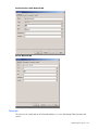
Customizing console switch and server properties ..................................................................................... 164
General tab ................................................................................................................................ 164
Telnet tab ................................................................................................................................... 166
Network tab ............................................................................................................................... 169
iLO tab ...................................................................................................................................... 171
Information tab............................................................................................................................ 171
Connections tab .......................................................................................................................... 173
Customizing options .............................................................................................................................. 174
Creating custom field labels .......................................................................................................... 174
Modifying the selected view on startup........................................................................................... 177
Changing the default browser ....................................................................................................... 177
Using Direct Draw ....................................................................................................................... 177
Assigning units to sites, departments, locations, or folders........................................................................... 177
Deleting and renaming a unit.................................................................................................................. 178
Deleting a unit, site, department, location, or folder ......................................................................... 178
Contents
5
Renaming a unit, site, department, location, or folder....................................................................... 179
Managing local databases ..................................................................................................................... 179
Saving local databases ................................................................................................................ 179
Exporting local databases ............................................................................................................ 180
Loading local databases............................................................................................................... 181
Using directory services integration............................................................................................. 182
Using LDAP .......................................................................................................................................... 182
LDAP Authentication Only mode.............................................................................................................. 182
LDAP Authentication and Access Control mode ......................................................................................... 183
LDAP Authentication and Access Control Query types ................................................................................ 183
Query modes .............................................................................................................................. 184
Enabling directory services integration ..................................................................................................... 186
Entering the default LDAP license key ....................................................................................................... 188
Configuring LDAP parameters ................................................................................................................. 189
Server Parameters tab .................................................................................................................. 190
Search Parameters tab ................................................................................................................. 190
Query Parameters tab .................................................................................................................. 191
Console switch and server query modes ................................................................................................... 193
Setting up the Active Directory for performing group attribute mode queries.................................................. 198
Troubleshooting ........................................................................................................................ 200
Troubleshooting chart ............................................................................................................................ 200
Upgrading the firmware ............................................................................................................ 203
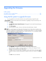
Using the file system to upgrade firmware ................................................................................................ 203
Using TFTP for firmware upgrades ........................................................................................................... 204
TFTP for Linux operating systems .................................................................................................... 204
Upgrading the firmware using TFTP on Linux operating systems ......................................................... 205
HP IP Console Switch directory services integration setup tutorial.................................................... 208
HP IP Console Switch directory service setup............................................................................................. 208
Hardware configuration used for this example .......................................................................................... 208
Settings used for this example ................................................................................................................. 209
Authentication and group-level access controls .......................................................................................... 209
Authentication only................................................................................................................................ 220
LDAP client behavior overview ................................................................................................... 222
UID masks (simple and complex) ............................................................................................................. 222
Active Directory attributes that can be used as credentials................................................................. 222
Attributes initialized during creation of a new user object ................................................................. 222
Additional attributes available in user properties ............................................................................. 226
Additional attributes available through the ADSI Editor..................................................................... 227
UID mask for single factor credentials ...................................................................................................... 228
UID mask for multiple factor credentials.................................................................................................... 236
Serial Session Viewer terminal emulation modes........................................................................... 238
Terminal emulation modes overview ........................................................................................................ 238
VT terminal emulation................................................................................................................... 238
VT102 terminal emulation............................................................................................................. 238
VT100 terminal emulation............................................................................................................. 239
VT220 terminal emulation............................................................................................................. 243
VT52 terminal emulation............................................................................................................... 245
VT320 terminal emulation............................................................................................................. 246
Keyboard and mouse shortcuts ................................................................................................... 249
Contents
6
Divider pane keyboard and mouse shortcuts ............................................................................................. 249
Group view control keyboard and mouse shortcuts .................................................................................... 249
List view keyboard and mouse operations................................................................................................. 250
Acronyms and abbreviations...................................................................................................... 251
Glossary .................................................................................................................................. 256
Index....................................................................................................................................... 263
Contents
7
Product overview
In this section
HP IP Console Viewer overview ................................................................................................................. 8
System components .................................................................................................................................. 8
Features and benefits.............................................................................................................................. 10
Supported operating systems ................................................................................................................... 11
Browser requirements ............................................................................................................................. 11
Supported directory services.................................................................................................................... 11
System requirements ............................................................................................................................... 11
HP IP Console Viewer overview
The HP IP Console Viewer is a cross-platform management application that enables you to view, control,
and group console switches and the servers and network devices that are attached to them.
The HP IP Console Viewer:
•
Ensures compatibility with most popular operating systems and hardware platforms
•
Provides secure authentication, data transfers, and user name and password storage
•
Provides directory-based authentication with Microsoft® Active Directory by using LDAP
•
Places system control at the point of need
The HP IP Console Viewer enables you to install, discover, configure, and operate the following products:
•
HP IP Console Switches
•
HP Serial Console Servers (referred to as serial console switches in the HP IP Console Viewer)
•
Interface adapters
•
USB 2.0 with Virtual Media
•
PS2 with Virtual Media
•
PS2
•
USB
•
Serial
•
HP Bladesystem CAT5 KVM
System components
The HP IP Console Viewer consists of the main window, Video Session Viewer, Serial Session Viewer,
and the Manage Console Switch window.
Main window
The HP IP Console Viewer utilizes a Microsoft® Windows® Explorer-like navigation with an intuitive splitscreen interface, providing you with a single point of access for all your servers. From the HP IP Console
Product overview 8
Viewer, you can easily perform tasks, such as installing and managing KVM console switches, installing
and managing serial console switches, launching a Video Session Viewer to a server or launching a
telnet/SSH session to a server. Built-in groupings, such as Servers, Sites, and Folders, provide an easy
way to view select console switches, serial console switches and servers. You can also create custom
groupings of console switches, serial console switches, and servers by adding folders that store shortcuts.
Additional groupings are provided based on the custom fields that you assign.
From the main window, you can select a server from a Unit list and then click an icon to launch a session
to it. You can also select a console switch and then click an icon to launch management and control
functions.
Video Session Viewer
The Video Session Viewer enables you to control the keyboard, video, and mouse functions of individual
servers. You can also use pre-defined macros for the server.
The Video Session Viewer can be launched to servers on the following console switches:
•
HP 2 x 1 x 16 IP Console Switch with Virtual Media [PN: AF601A]
•
HP 4 x 1 x 16 IP Console Switch with Virtual Media [PN: AF602A]
•
HP 1 x 1 x 16 IP Console Switch [PN: 262585-B21]
•
HP 3 x 1 x 16 IP Console Switch [PN: 262586-B21]
•
HP 2 x 16 Server Console Switch with Virtual Media (when tiered and integrated with an HP IP
Console Switch using a CAT5 cable) [PN: AF600A]
•
HP 1 x 8 Server Console Switch (when tiered and integrated with an HP IP Console Switch
using a CAT5 cable) [PN: 336044-B21]
•
HP 2 x 16 Server Console Switch (when tiered and integrated with an HP IP Console Switch
using a CAT5 cable) [PN: 336045-B21]
•
Compaq legacy analog switches (when attached to an interface adapter)
•
1 x 4 [PN: 400336 (-001)(-291)(-B31)]
•
1 x 8 [PN: 400337 (-001)(-291)(-B31)]
•
2 x 8 [PN: 400338 (-001)(-291)(-B31)]
•
2 x 8 (48 VDC) [PN: 400542-B21]
Serial Session Viewer
The Serial Session Viewer enables you to establish serial sessions with individual servers that support
telnet or SSH. You can configure user preferences for all sessions and session properties for each server.
The Serial Session Viewer offers a scripting function for automatic server login and a logging function for
saving session data to a file. The console switch settings indicate whether SSH or plaintext (non-encrypted)
sessions (or both) are allowed.
The Video Session Viewer can be launched to servers on the following serial console switches:
•
HP 16-Port Serial Console Server
•
HP 48-Port Serial Console Server
Manage Console Switch windows
Each Manage Console Switch window is implemented as a network management module that supports a
console switch. The Manage Console Switch window contains tabs, and each tab represents a top-level
function category for the console switch. For example, the Manage Console Switch window tabs might be
Settings, Status, and Tools. The number and content of tabbed panels differs for each console switch.
Product overview 9
Features and benefits
•
Ease of installation
Auto discovery of managed console switches enables you to locate and install new console switches.
An installation wizard simplifies the task of initial configuration, and an online help application is
available to assist you with installation tasks.
•
Ease of configuration
The HP IP Console Viewer has an intuitive GUI-based configuration with tools to load and save
managed console switch-based configuration tables and managed console switch groupings user
tables.
•
Ease of update
The HP IP Console Viewer contains easy-to-use tools to initiate flash upgrades, distribute database
files, and back up and restore managed console switch-based configurations.
•
Ease of management
The HP IP Console Viewer enables you to add and manage multiple console switches and servers in
one system. After a console switch or server is installed, you can configure the console switch
parameters, launch, share or preempt user video sessions, and execute numerous control functions.
From the intuitive Manage Console Switch window, you can enable SNMP traps, configure target
servers, cascade console switches, and manage user databases.
•
Increased customization capabilities
The HP IP Console Viewer can be customized to meet your specific needs. Unit names, field names,
icons, and macros can be customized for maximum flexibility and convenience.
•
Virtual Media capability
The HP IP Console Viewer enables you to map a mass storage device or a CD/DVD drive on the
local computer as a virtual drive on a target server. You can also add and map an .iso or floppy
image file on the local console switch as a virtual drive on the target server.
•
Increased capacity
NOTE: The HP IP Console Viewer database is designed to store up to 25 managed console switches and
up to 1,024 target servers (devices). If more units are added, performance may decrease.
Each managed KVM console switch supports up to 64 internal user accounts and has client support
for multiple simultaneous user sessions, depending on the model:
•
1 x 1, where one remote user session is supported
•
2 x 1, where two remote user sessions are supported
•
3 x 1, where three remote user sessions are supported
•
4 x 1, where four remote user sessions are supported
Each managed serial console switch supports up to 64 internal user accounts and can support client
sessions for all ports simultaneously.
•
Increased security
The HP IP Console Viewer provides secure managed switch-based authentication, data transfers, and
user name and password storage. With multiple levels of access control, Admin and User, you can
set server device-specific access rights and inter-operate with existing firewalls, VPN, and NAT-based
networks.
•
Serial console switch support
The HP IP Console Viewer enables you to install and manage serial console switches. You can also
launch a Serial Session Viewer to view connected serial devices.
Product overview
10
Directory services integration (LDAP)
Directory services integration, or LDAP, offers the following features and benefits:
•
Authenticates and authorizes users from a shared database
•
Controls user privileges (A user can be disabled globally with one change.)
•
Enables users to use their domain credentials
•
Does not require manual password synchronization when the user password is changed in the
directory (It is changed everywhere.)
•
Manages access controls from a single administration point
Supported operating systems
•
Microsoft® Windows® 2000 Workstation Service Pack 4
•
Microsoft® Windows® 2000 Server Service Pack 4
•
Microsoft® Windows® XP (Home and Professional) Service Pack 2
•
Microsoft Windows™ Server 2003 Service Pack 1
•
Red Hat Enterprise Linux 3.0 WS
•
Red Hat Enterprise Linux 4.0 WS
•
SUSE Linux Enterprise Server 8
•
SUSE Linux Enterprise Server 9
•
SUSE Linux 9.2
•
SUSE Linux 9.3
IMPORTANT: To ensure that you have the latest software, see the HP website
(http://www.hp.com/go/kvm).
Browser requirements
•
Microsoft® Internet Explorer 5.5 or higher (Microsoft® Windows® operating systems only)
•
Mozilla 1.4 or higher
•
Netscape 6.0 or later
•
Firefox 1.0 or later
Supported directory services
Microsoft® Active Directory on:
•
Windows® Server 2000
•
Windows Server™ 2003
System requirements
The following is a list of the hardware and browser requirements for running the HP IP Console Viewer on
the supported operating systems. Configurations with less than the recommended requirements are not
supported.
•
500-MHz Intel® Pentium® III processor
Product overview
11
•
256 MB RAM
•
10 or 100–BaseT NIC (100 recommended)
•
XGA video with graphics accelerator (minimum)
•
800 x 600 desktop size (minimum)
•
65, 536 (16-bit) colors (recommended)
Product overview
12
Installation
In this section
Setting up the HP IP Console Switch ......................................................................................................... 13
Establishing LAN connections .................................................................................................................. 14
Installing the HP IP Console Viewer .......................................................................................................... 15
Launching the HP IP Console Viewer......................................................................................................... 16
Configuring the HP IP Console Viewer ...................................................................................................... 16
Setting up the HP IP Console Switch
Before installing the HP IP Console Viewer, see the following sections to be sure that you have all the
items necessary for proper installation and that you synchronize your mouse pointers.
1.
Adjust the mouse acceleration on each server to none.
2.
Install the console switch hardware, connect the interface adapters, and connect the keyboard,
monitor, and mouse to the analog ports.
3.
Connect a terminal or a workstation running emulation software, such as HyperTerminal, to the
configuration serial port on the rear panel of the console switch, and set up the network parameters.
You can also set the network parameters from the HP IP Console Viewer, or the OSD on an HP IP
Console Switch with Virtual Media.
4.
Using the local analog workstation, input all server names through the OSD, or you can change the
server names of the interface adapters through the Manage Console Switch window.
Synchronizing your mouse pointers
When viewing a server attached to your console switch, the viewer displays the mouse pointer of the
accessed server and the mouse pointer for your local computer by default. The pointer for the server
follows the movement of the local pointer. To maintain pointer synchronization, the mouse speed and
accelerations must be configured correctly on the target server.
Before beginning, synchronize your mouse pointers through the local port, on servers attached to console
switches.
NOTE: HP recommends that all Windows® systems attached to the console switch use the default
Windows® mouse driver.
Windows operating systems
To synchronize the mouse pointers for Windows® operating systems (using the default drivers):
1.
From the desktop, select Start>Setting>Control Panel, and double-click Mouse.
2.
Select Motion.
3.
For Windows® 2000, set the Speed setting to 50% (default) and the Acceleration setting to None.
-or-
Installation 13
For Windows Server™ 2003, set the Speed setting to 50% (default), and clear the Enhance
Pointer Precision option.
Linux operating systems
NOTE: The following Linux example uses Red Hat 3.0. For more information, refer to your Linux operating
system's HELP or documentation.
To synchronize the mouse pointers for Linux operating systems (GNOME):
1.
Click the main menu.
2.
From the main menu task list, select Programs>Settings>Peripherals.
3.
From the Peripherals task list, select Mouse. The Mouse Configuration window appears. In this
window, you can set the mouse to be either right-handed or left-handed and adjust the mouse motion
by changing the threshold and adjusting the acceleration to the fourth position from the far left.
To synchronize the mouse pointers for Linux operating systems (KDE):
1.
Go to the main menu, and select K Menu>KDE Control Center>Input Devices>Mouse.
2.
Set the acceleration to 1X.
3.
Apply the settings, and click OK.
Establishing LAN connections
To connect an HP IP Console Switch to a network:
NOTE: Although 10Base–T Ethernet can be used, HP recommends a dedicated, switched 100Base–T
network (or better) for improved performance. HP IP Console Switches with Virtual Media are capable of
1G.
Connect the network cable from the LAN port on the rear panel of the HP IP Console Switch to the
network, and then power on all attached systems. The following ports must be open on your network, for
both UDP and TCP protocols, for the HP IP Console Viewer to work properly:
•
2068
•
8192
•
3211
•
161
•
162
•
389 (LDAP)
•
636 (secure LDAP)
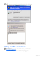
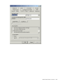
Windows XP SP1 or newer
To add a console switch without a preconfigured IP address and when the client software application is
not listed in the Windows® XP Firewall Exceptions List, the program must be added to the list of
Windows® XP Firewall Exceptions, and its scope must be set to the whole Internet.
NOTE: When installing the HP IP Console Viewer on a Windows Server™ 2003 server, if you do not get a
security dialog box and the installation program stops, you might need to restart the server to get the security
dialog.
Installation 14
NOTE: At the program startup, if you select Unblock, unblock is the default setting.
Installing the HP IP Console Viewer
IMPORTANT: To ensure that you have the latest software, see the HP website
(http://www.hp.com/go/kvm).
To install the HP IP Console Viewer on Windows® operating systems:
Installation 15
1.
Insert the HP IP Console Viewer CD in to the CD-ROM drive. If AutoPlay is supported and enabled,
the setup program starts automatically.
-orIf your system does not support AutoPlay, set the default drive to the CD-ROM drive letter, and
execute the following command to start the install program:
<CD-ROM drive>:\WIN32\SETUP.EXE
2.
Follow the on-screen instructions.
To install the HP IP Console Viewer on Linux operating systems:
1.
Insert the HP IP Console Switch Viewer CD into your CD-ROM drive.
•
If you are using Red Hat and SUSE Linux, the CD mounts automatically. Proceed to step 2.
•
If the CD does not mount automatically, issue the mount command manually. The following is an
example of a typical mount command:
mount -t iso9660 device_file mount_point
Where device_file is the system-dependant device file associated with the CD and
mount_point is the directory that is used to access the contents of the CD after it is mounted.
Typical values include /mnt/cdrom or /media/cdrom.
2.
Open a command window and navigate to the CD mount point. For example, cd/mnt/cdrom.
3.
Enter the following command to start the installation, sh ./linux/setup.bin.
4.
Follow the on-screen instructions.
Launching the HP IP Console Viewer
•
To launch the HP IP Console Viewer on all Windows® operating systems, select
Start>Programs>HP IP Console Viewer.
-orFrom the desktop, double-click HP IP Console Viewer. The HP IP Console Viewer launches.
•
To launch the HP IP Console Viewer on Linux operating systems:
If the product was installed in the default install directory (/usr/lib/IPViewer), then execute the
following command from a shell:
./IPViewer
-orIf the product was installed in a directory other than the default, then execute the following command
from a shell:
<path>/IPViewer
-orFrom the desktop, double-click HP IP Console Viewer. The HP IP Console Viewer launches.
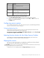
Configuring the HP IP Console Viewer
IMPORTANT: To ensure that you have the latest software, see the HP website
(http://www.hp.com/go/kvm).
1.
Install the HP IP Console Viewer on each HP IP Console Viewer client.
2.
From one of the HP IP Console Viewer clients, launch the HP IP Console Viewer.
Installation 16
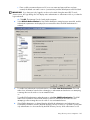
3.
Click New Console Switch to add the new console switch to the HP IP Console Viewer database.
The New Console Switch wizard appears.
4.
If you previously configured the IP address, select Yes, the product already has an IP
address. You are prompted to provide the IP address of the console switch and complete the
wizard.
-orIf you did not configure the IP address, select No, the product does not have an IP address.
You are prompted to assign an IP address, network mask, and gateway. The HP IP Console Viewer
finds the console switch and all interface adapters, or ports (for serial console switches), attached to
it. These names appear in the HP IP Console Viewer main window.
5.
(Optional) Add additional console switches.
6.
Set properties and group servers as desired into Sites or Folders through the main window.
7.
Configure the console switch for access by clicking Manage Console Switch.
When prompted for login credentials, login using the Override Administrator User name (Admin).
The password is not set on new console switches. Remember to set the Override Admin Password
and keep it secure.
If local authentication is to be used select the User category and configure user names. For
information on adding internal users, see "Configuring user accounts (on page 42)" or "Configuring
user accounts for serial console switches (on page 108)."
If LDAP is to be used for authentication and authorization the console switch must be configured to
access the directory server. For information on configuring LDAP Authentication, see "Using directory
services integration (on page 182)."
Serial console switches can be configured for internal authentication, LDAP authentication, and also
RADIUS authentication. For more information, see "Configuring authentication parameters for serial
console switches (on page 99)."
8.
After one HP IP Console Viewer client is configured, select File>Database>Save to save a copy
of the database with all the settings, and then share the file so that it can be loaded.
9.
From the second HP IP Console Viewer client, select File>Database>Load, and browse to find the
file you saved.
10. If interface adapters are added, moved, deleted, or renamed after you loaded this file,
resynchronize your local database with the console switch by clicking Manage Console Switch,
selecting Settings>Servers, and clicking Resync.
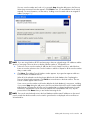
11. To access a server attached to your console switch, select the desired server in the main window,
and click Launch KVM Session to launch a server session.
-orTo access a server attached to your serial console switch, select the desired server in the main
window, and click Launch Serial Session to launch a server session.
If SSH is enabled on the serial console switch to which the selected server is connected, then HP IP
Console Viewer automatically launches a secure session using SSH2. If SSH is not enabled, then a
plaintext Telnet session launches. If both SSH and plaintext sessions are enabled, then you are
prompted to select between launching an SSH or plaintext session, and are given the option to save
your preference for future sessions launched during this HP IP Console Viewer session. To clear your
preference select the Tools>Clear Login Credentials menu option.
12. Adjust the resolution by selecting View>Auto Scale, and click Maximize. Select
Tools>Automatic Video Adjust for the server video in the Video Session Viewer.
13. After setting the mouse properties, click mouse synchronization in the HP IP Console Viewer
menu bar.
Installation 17
Navigating the HP IP Console Viewer
In this section
HP IP Console Viewer components overview.............................................................................................. 18
Viewing the main window....................................................................................................................... 18
Main window features ............................................................................................................................ 19
Auto searching for a server in the list view ................................................................................................ 20
Searching for a server in the local database.............................................................................................. 20
HP IP Console Viewer components overview
The HP IP Console Viewer consists of several components: the main window, the Manage Console Switch
window, the Video Session Viewer component, and Serial Session Viewer component. After you launch
the HP IP Console Viewer, the main window appears. The main window enables you to view, access,
manage, and create custom groupings for all the supported units in the data center.
When you select a server, you can click Launch KVM Session in the main window to launch the Video
Session Viewer. This component enables you to control the keyboard, monitor, and mouse functions of
individual servers. If the target device has a connection to a serial console switch, click the Launch Serial
Session icon to establish a telnet or SSH session to the target.
When you select a console switch, you can click Manage Console Switch in the main window to
launch the Manage Console Switch window. This window enables you to configure and control the
console switch.
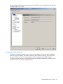
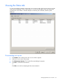
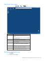
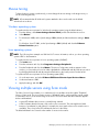
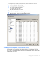
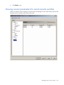
Viewing the main window
The main window is divided into several different views. These views change based on the type of servers
selected or the task you want to complete. Click one of the views to see your system organized by
categories, such as console switches, servers, sites, or folders. The default display for the main window
can be configured by the user. By default, each time you launch the main window, it reads the local
database to determine which view to display.
Navigating the HP IP Console Viewer 18
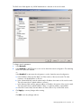
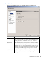
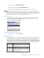
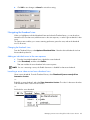
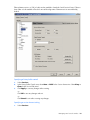
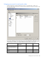
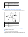
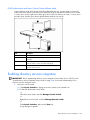
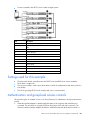
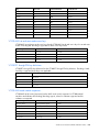
Main window features
Position
Feature
Function
1
Title bar
Provides the title of the HP IP Console Viewer
2
Menu bar
Contains six menus (File, Edit, View, Tools,
Window, and Help)
3
View Selector tabs
Contains four tabs (Console Switches, Servers,
Sites, and Folders)
4
Group view
Contains a tree view representing the groups
that are selected from the tab view (The group
view also controls what appears in the
selected view.)
5
List view
Displays a list in the currently selected group
view or the results of a search executed from
the search bar
6
Status bar
Displays the number of items shown in the list
view
7
Selected view
Displays the search bar, list view, and task
window
8
Search bar
Enables you to filter the list view displayed in
the selected view, based on the text entered
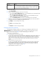
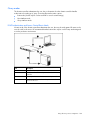
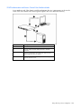
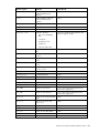
Navigating the HP IP Console Viewer 19
Position
Feature
Function
9
Task window
Contains buttons representing tasks that can
be executed (Some buttons are dynamic,
based on the type of items selected in the list
view, and other buttons are fixed and always
present.)
Auto searching for a server in the list view
1.
Click Servers, and click any item in the List view.
2.
Begin entering the first few characters of a server name. The highlight moves to the first server name
beginning with those characters.
To reset the search so you can find another server, pause for a few seconds, and enter the first few
characters of the next server.
Searching for a server in the local database
1.
Click Servers.
2.
Insert your cursor in the Search text box, and enter the search information.
3.
Click Search.
4.
Review the results of your search.
-orClick Clear Results to display the entire list again.
Navigating the HP IP Console Viewer 20
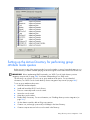
Adding and discovering console switches
In this section
Adding console switches ......................................................................................................................... 21
Discovering one or more console switches with the Discover Wizard ........................................................... 27
Managing multiple connections................................................................................................................ 31
Server naming ....................................................................................................................................... 32
Managing cached credentials.................................................................................................................. 33
Adding console switches
Before a console switch can be accessed through the HP IP Console Viewer, you must add it to the HP IP
Console Viewer database. After the console switch has been manually added or discovered, it appears in
the list view.
If an IP address has already been assigned to the console switch, the HP IP Console Viewer automatically
discovers it by searching for an exact IP address or an address range. If an IP address has not yet been
assigned, you must manually add the console switch. If you are installing multiple console switches, HP
recommends using the Discover Wizard. If you are installing a single console switch, HP recommends
using the New Console Switch Wizard.
NOTE: For KVM console switches, HP recommends that you assign names to the target servers in the
console switch OSD before adding them to the HP IP Console Viewer. For serial console switches, the server
name should be configured on the associated serial console switch port using the CLI. For more information,
refer to the documentation included with the serial console switch.
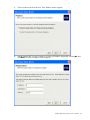
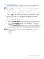
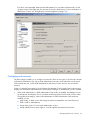
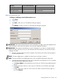
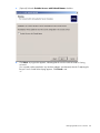
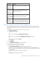
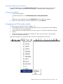
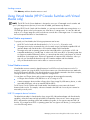
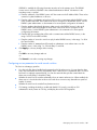
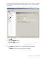
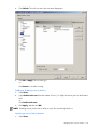
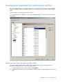
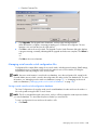
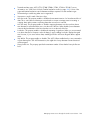
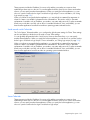
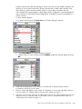
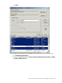
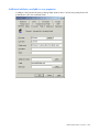
Adding a console switch without an assigned IP address
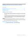
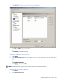
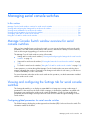
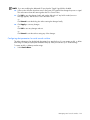
1.
Select File>New>Console Switch, or click New Console Switch.
Adding and discovering console switches 21
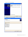
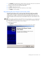
The New Console Switch Wizard appears.
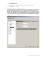
2.
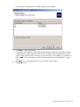
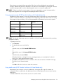
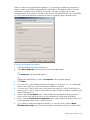
Click Next. The Product Type window appears.
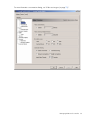
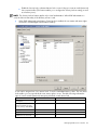
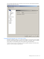
Adding and discovering console switches 22
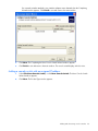
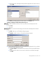
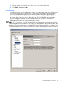
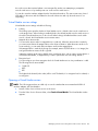
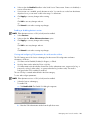
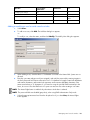
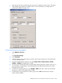
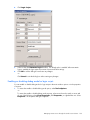
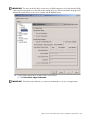
3.
Select a product from the product list. The IP Address window appears.
4.
Indicate that the HP IP Console Switch does not have an IP address assigned by selecting No, and
click Next. The Network Address window appears.
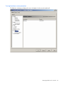
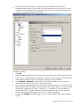
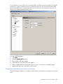
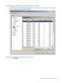
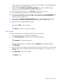
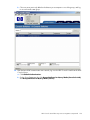
Adding and discovering console switches 23
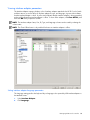
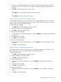
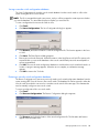
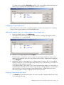
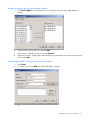
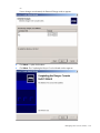
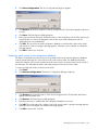
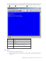
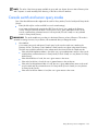
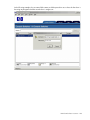
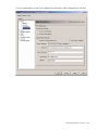
5.
Enter the IP address, subnet mask, and gateway for the console switch, and click Next. The HP IP
Console Viewer searches for the console switch and interface adapter IDs and server names
associated with the particular console switch. The Found window appears.
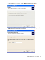
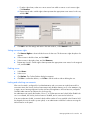
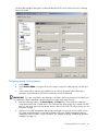
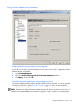
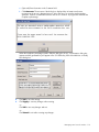
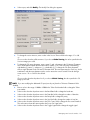
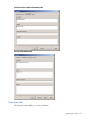
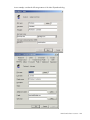
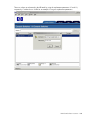
6.
Click Next. If a cascade legacy analog console switch attached to an interface adapter is detected,
then the Enter Cascade Switch Information window appears.
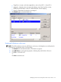
a. The Assign Cascade Switch dialog box displays a list of all the interface adapters attached to a
cascade switch. Associate the appropriate console switch from the dropdown list for each
interface adapter that has a console switch attached.
b. The Existing Cascade Switches dialog box contains a list of all the current console switches
defined in the database. Click Add, Modify, or Delete to alter the list.
The HP IP Console Viewer searches only for the number of servers designated by the console
switch type (user definable).
After a cascade switch has been added to an Existing Cascade Switches list, you can modify or
delete the cascade switch displayed by selecting the cascade switch and clicking Modify or
Delete.
-or-
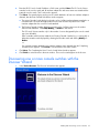
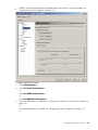
Adding and discovering console switches 24
If no cascade switches attached to any interface adapters were detected, then the Completing
Wizard window appears. Click Finish to exit and return to the main window.
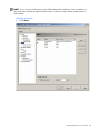
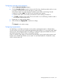
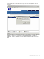
7.
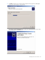
Click Next. The Completing the New Console Switch Wizard window appears.
8.
Click Finish to exit and return to the main window. The console switch displays in the list view.
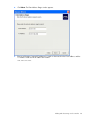
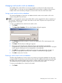
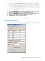
Adding a console switch with an assigned IP address
1.
Select File>New>Console Switch, or click New Console Switch. The New Console Switch
Wizard window appears.
2.
Click Next. The Product Type window appears.
Adding and discovering console switches 25
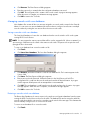
3.
Select a product from the product list, and click Next. The IP Address window appears.
4.
Indicate that the HP IP Console Switch has an IP address assigned to it by selecting Yes, and click
Next. The Locate IP Console Switch window appears.
Adding and discovering console switches 26
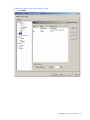
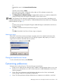
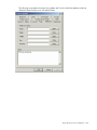
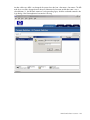
5.
Enter the HP IP Console Switch IP address or DNS name, and click Next. The IP Console Viewer
searches for the console switch and all interface adapter IDs and server names associated with the
particular console switch. The Found window appears.
6.
Click Next. If a cascade legacy analog console switch attached to at least one interface adapter is
detected, then the Enter Cascade Information window appears.
a. The Assign Cascade Switch dialog box displays a list of all the interface adapters attached to a
cascade switch. Associate the appropriate console switch from the dropdown list for each
interface adapter that has a console switch attached.
b. The Existing Cascade Switches dialog box contains a list of all the current console switches
defined in the database. Click Add, Modify, or Delete to alter the list.
The IP Console Viewer searches only for the number of servers designated by the console switch
type (user definable).
After a cascade switch has been added to an Existing Cascade Switches list, you can modify or
delete the cascade switch displayed by selecting the cascade switch and clicking Modify or
Delete.
-orIf no cascade switches attached to any interface adapters were detected, then the Completing
Wizard window appears. Click Finish to exit and return to the main window.
7.
Click Next. The Completing the New Console Switch Wizard window appears.
8.
Click Finish to exit and return to the main window. The console switch appears in the list view.
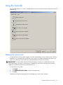
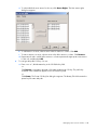
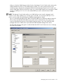
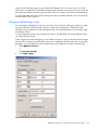
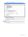
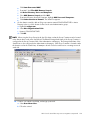
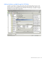
Discovering one or more console switches with the
Discover Wizard
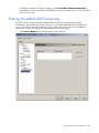
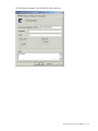
1.
Select Tools>Discover. The Discover Wizard window appears.
Adding and discovering console switches 27
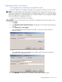
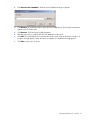
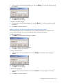
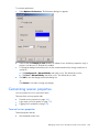
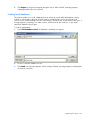
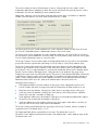
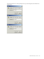
2.
Click Next. The Enter Address Range window appears.
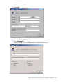
3.
Enter a valid range of network IP addresses to search on the network in the From Address: and the
To Address: fields. Use the IP address dot notation:
xxx.xxx.xxx.xxx.
Adding and discovering console switches 28
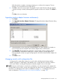
4.
Click Next. The Searching Network window appears. Progress text indicates how many addresses
have been probed from the total number specified by the range and the number of IP console
switches found.
If one or more new console switches are discovered, the Select Console Switches window appears.
From this window, you can select the console switches to add to the local database. Continue to step
6.
-or-
Adding and discovering console switches 29
If no new console switches are found or if you pressed Stop during the add process, the Discover
Wizard was unsuccessful window appears. Click Finish to exit. You must add the console switch
manually. For more information, see the section, "Adding a console switch without an assigned IP
address (on page 21)."
NOTE: If you are using Windows XP SP2 and are trying to discover a broad range of IP addresses and the
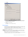
device you are trying to discover does not display, limit the number of TCP threads to ten.
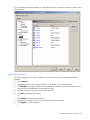
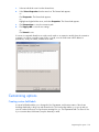
5.
Select one or more console switches to add from the Console Switch Found: box, and click the >
button to move the selection to the Console Switches to add: box. Repeat for all the console switches
that you want to add.
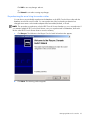
6.
Click Next. The Adding Console Switches window appears. A progress bar appears while new
console switches are added to the list.
When all of the selected consoles have been added to the local database, the Completing the
Discover Wizard window appears. Click Finish to exit and return to the main window. The new
console switches appear in the list view.
If one or more console switches could not be added to the local database for any reason, including
if you pressed Stop during the add process, the Discover Wizard Not All Console Switches Added
page appears. This page lists all of the console switches that you selected and the status for each.
The status is indicated if a console switch was added to the local database and if not, why the
process failed. Click Done when you are finished reviewing the list.
NOTE: If a console switch already exists in the local database with the same IP address as a discovered
console switch, then the discovered console switch is ignored and is not displayed on the next Discover
Wizard window.
Adding and discovering console switches 30
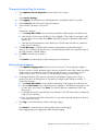
Managing multiple connections
A server that has connections to more than one console switch managed by the HP IP Console Viewer
usually appears as two different servers in the main window when the console switches are initially
discovered. For example, a server can have a serial console port connected to a serial console switch, in
addition to being connected to a kvm console switch.
You can configure such a server to appear only once, and the main window provides the valid
connection methods for accessing the server (for example, the Launch KVM Session and Launch Serial
Session task buttons). To configure a server to appear only once, the serial console switch port name and
the KVM console switch interface adapter must be set to the same name. You can rename the interface
adapter, or serial port, through the Servers category in the Manage Console Switch window.
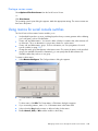
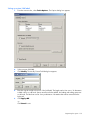
To rename an interface adapter through the HP IP Console Viewer:
1.
Access the console switch ("Accessing console switches" on page 34).
2.
Select Servers.
3.
Highlight the server in the Servers column that you want to modify. You can modify only one server
at a time.
4.
Click Modify. The Modify dialog box appears with the current name of the server as stored in both
the console switch and the client database (not necessarily the same).
5.
Enter the new name of the server in the New Name: field.
6.
Click OK to change the server name.
7.
Repeat steps 1 through 5 for every server name that you want to change.
8.
Click Apply to save any changes. This process dynamically updates the HP IP Console Viewer
database, the console switch and the interface adapter simultaneously.
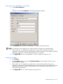
To rename the serial ports on the serial console switch through the HP IP Console Viewer:
1.
Access the serial console switch ("Accessing console switches" on page 34).
2.
Select Servers.
3.
Select the server in the Servers column that you want to modify. You can modify only one server at a
time.
4.
Click Modify. The Modify dialog box appears with the current name of the server as stored in both
the console switch and the client database (not necessarily the same).
5.
Enter the new name of the server in the New Name: field.
6.
Click OK to change the server name.
7.
Repeat steps 1 through 5 for every server name that you want to change.
8.
Click Apply to save any changes. This process dynamically updates the HP IP Console Viewer
database, the console switch and the interface adapter simultaneously.
To rename the server locally:
1.
Using the serial console switch CLI, issue a Port Set command with the Name parameter. For
example, if you want the server connection to the serial console switch to have the same name as its
KVM console switch connection, change the name using the serial console switch CLI. For more
information on CLI commands, see the documentation included with the serial console server.
2.
Using the KVM console switch OSD, configure the server name with the Names dialog box. For
more information on the OSD, see the user guide included with your KVM console switch.
3.
Resynchronize the server list in the appropriate Manage Console Switch window. For more
information, see "Resynchronizing the server listing for console switches (on page 57)" or
"Resynchronizing the server listing for serial console switches (on page 132)."
Adding and discovering console switches 31
For example, if you changed the server name on the serial console switch, resynchronize the server
list in the Manage Serial Console Switch window.
Server naming
The HP IP Console Viewer requires that each KVM console switch, serial console switch, and server have
a unique name. The HP IP Console Viewer uses the following procedure to generate a unique name for a
server whose current name conflicts with another name in the database.
During background operations (such as an automated operation that adds or modifies a name or
connection), if a name conflict occurs, the conflicting name is automatically made unique. This is done by
appending a tilde (~) followed by an optional set of digits. The digits are added in cases where adding
the tilde alone does not make the name unique. The digits start with a value of one and are incremented
until a unique name is created.
During normal operations, if you specify a non-unique name, a message appears informing you that the
server name is already in the database and you are prompted to merge server records. This option is
useful when a target server can be managed by both the KVM session and a serial interface. For more
information, see "Modifying server names (on page 56)" or "Modifying server names for serial console
switches (on page 131)."
Server name displays
When a KVM console switch is added, the server names retrieved from the KVM console switch or serial
console switch are stored in the HP IP Console Viewer database. The operator can then rename a server
in the main window, and the new name is stored in the database and used in various HP IP Console
Viewer component screens. This new server name is not communicated to the KVM console switch or
serial console switch.
Because HP IP Console Viewer is a decentralized management system, the name assigned to a server on
the console switch or serial console switch can be changed at any time without updating the HP IP
Console Viewer database. This feature enables each operator to customize a particular HP IP Console
Viewer view of the list of servers being managed.
Because there can be more than one name associated with a single server, one on the KVM console
switch or serial console switch, and one in the HP IP Console Viewer, the HP IP Console Viewer uses the
following rules to determine which name appears:
•
The main window shows only the servers listed in its database, with the name specified in the
database. In other words, the main window does not talk to the console switch or serial console
switch to obtain server information.
•
The Manage Console Switch window displays information retrieved from the console switch, except
where noted.
•
The Resync Wizard (which is used to resynchronize the server list in the Manage Console Switch
window) overwrites locally defined server names only if the console switch server name has been
changed from the server value in the Manage Console Switch window (its default value). For
example, in KVM console switches, the default server name values are the EID of the interface
adapter to which they are attached. In serial console switches, the default server name values are
comprised of the console switch's MAC Address and the port number of the port to which the server
is attached. Non-default server names that are read from the console switch during a
resynchronization are allowed to override the locally defined names.
Adding and discovering console switches 32
Sorting displays
In certain displays, an HP IP Console Viewer component displays a list of items with columns of
information about each item. If a column header contains an arrow, you can sort the display by that
column in ascending or descending order.
To sort a display by a column header, click the column header. The items in the list will be sorted
according to that column. An upward-pointing arrow indicates the list is sorted by that column header in
ascending order. A downward-pointing arrow indicates the list is sorted by that column header in
descending order.
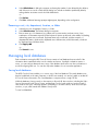
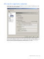
Managing cached credentials
To access KVM console switches, serial console switches, and servers, you must first enter a user name
and password (credentials). The HP IP Console Viewer uses credential caching, which captures
credentials upon first use and automates the authentication of subsequent unit connections.
After successfully authenticating, cached credentials are used whenever you access other units during that
HP IP Console Viewer session, and the user name and password prompt does not appear unless
authentication with the cached credentials fails.
Clearing login credentials
You can clear cached credentials at any time.
NOTE: Clearing login credentials also clears your preference for SSH versus plaintext serial sessions, if
previously saved.
To clear login credentials:
1.
Select Tools>Clear Login Credentials. A message appears.
2.
Click OK to exit.
Adding and discovering console switches 33
Accessing console switches
In this section
Accessing console switches overview........................................................................................................ 34
Accessing console switches overview
When you click the Console Switches icon, you see a list of the console switches currently defined in the
local database.
To access a console switch, first log in with a valid password and user name. After you log into the
console switch, the HP IP Console Viewer caches the user name and password into memory for the
duration of the HP IP Console Viewer session. All HP IP Console Switch Viewer communications to the
console switch use an SMP connection.
NOTE: You can clear the login credentials. For information on clearing the login credentials, see "Clearing
login credentials (on page 33)."
To access a console switch:
1.
Click Console Switches to display the console switches in the selected view.
2.
Double-click the desired console switch. A login dialog box appears.
-orSelect the console switch, and click Manage Console Switch. A login dialog box appears.
-orRight-click the console switch, and select Manage Console Switch from the resulting list. A login
dialog box appears.
-orClick Console Switches, and press Enter. A login dialog box appears.
3.
Enter a valid user name and password. If a new user name and password have not been created,
the Override Admin. account can be used. The default user name for this account is Admin (casesensitive), and the default password field is blank.
IMPORTANT: If you have previously logged in to the console switch during the same HP IP Console
Viewer session, the login dialog does not display unless authentication or authorization fails or you clear the
login credentials.
4.
Click OK. The Manage Console Switch window appears. For information on managing console
switches, see "Managing KVM console switches (on page 35) or "Managing serial console switches
(on page 94)."
-orClick Cancel to exit without logging in.
Accessing console switches 34
Managing KVM console switches
In this section
Manage Console Switch window overview for KVM console switches .......................................................... 35
Viewing and configuring parameters through the Settings tab...................................................................... 35
Viewing the Status tab ............................................................................................................................ 66
Using the Tools tab................................................................................................................................. 67
Manage Console Switch window overview for KVM
console switches
After you have installed a new KVM console switch, you can view and configure unit parameters, view
and control currently active video sessions, and execute a variety of control functions, such as rebooting
and upgrading your KVM console switch.
The Manage Console Switch window consists of three tabs:
•
Settings tab for KVM console switches ("Viewing and configuring parameters through the Settings
tab" on page 35)
•
Status tab for KVM console switches ("Viewing the Status tab" on page 66)
•
Tools tab for KVM console switches ("Using the Tools tab" on page 67)
Some operations that you initiate through the Manage Console Switch window can cause a dialog box to
appear, indicating that a reboot is required for the change to take effect. In such cases, you can choose
to reboot immediately or wait to reboot later.
NOTE: References to the local user refer to an OSD user connected to the console switch.
For more information about the KVM console switch and its operations, see the documentation included
with the KVM console switch.
Viewing and configuring parameters through the Settings
tab
The Settings tab enables you to display an expandable list of categories covering a wide range of
parameters for the console switch. When a category is selected, the parameters associated with that
category are read from the console switch, the database, or both. You can modify those parameters and
send changes securely back to the console switch through the SMP.
Configuring global parameters
The Global category enables you to view the Product Type, Serial Number (EID), and the Language
settings for the console switch.
Managing KVM console switches 35
The Serial Number (EID) field contains information for the HP IP Console Switch hardware and the EID
attached to that console switch.
Configuring network parameters
The Network subcategory enables you to view the network settings of a console switch, including the
Name (read-only), IP Address, Subnet Mask, Gateway, MAC Address (read-only), LAN Speed, DNS
Servers, and Bootp settings. You can change the console switch name in the SNMP category.
The DNS servers can be used to find domain controllers during LDAP authentication and authorization
operations, but HP recommends using IP addresses.
Managing KVM console switches 36
The DNS Server fields appear only if LDAP Authentication is licensed on the console switch.
To change network parameters:
1.
Select Network.
2.
Select Enabled if a BOOTP server is to be used to obtain the network configuration. The remaining
fields on this panel are disabled.
-orSelect Disabled if a static network configuration is used to obtain the network configuration.
a. In the IP Address field, enter the address in IP dot notation of the console switch. The value
cannot be a loopback address or all zeros.
b. In the Subnet Mask field, enter the subnet mask in IP address dot notation of the console switch.
The value cannot be a loopback address or all zeros.
c. In the Gateway field, enter the gateway address in IP address dot notation of the console switch.
The value cannot be a loopback address. If there is no gateway address, enter 0.0.0.0.
d. In the DNS Servers fields, enter the address in IP dot notation of up to three DNS servers.
3.
Click Apply to save any changes without exiting.
-orClick OK to save any changes and exit.
Managing KVM console switches 37
Configuring session parameters
The Sessions subcategory enables you to specify the active Video Session Timeout, which configures the
console switch to close an inactive video session after a specified number of minutes.
NOTE: If a video session is associated with a reserved Virtual Media session, then the video session is not
subject to the video session timeout.
This subcategory also enables you to configure the preemption warning settings. Enabling the Video
session preemption timeout option enables you to specify the time (5 to 120 seconds) for which a
preemption warning message appears before a video session is preempted. If this option is not enabled,
preemption occurs without warning.
You can also set the SSL encryption levels to use for the encryption of keyboard and mouse data of all
video sessions to the console switch. You can also enable video encryption.
Video encryption is optional, but at least one Keyboard/Mouse encryption level must be selected.
The Sessions subcategory can also be used to enable Connection Sharing options. In the Connection
Sharing area, select sharing options as needed.
•
If you select Enable Share Mode, users can share KVM sessions for the same server.
•
If you select Automatic Sharing, secondary users can share KVM sessions without first requesting
permission from the primary user.
•
If you select Exclusive Connections, primary users can designate a KVM session as exclusive
(exclusive sessions cannot be shared).
•
If you select Stealth Connections, administrators can monitor a server and remain undetected.
You can also specify in the Input Control Timeout field the number of seconds the console switch will wait
for activity before transferring keyboard and mouse control from the primary user to the secondary user.
NOTE: The highest encryption level will be used, based on the following order (highest to lowest):
•
128-bit encryption
•
3DES
•
DES
Managing KVM console switches 38
For more information on connection sharing, see "Video session types (on page 75)."
Managing KVM console switches 39
Configuring Virtual Media parameters
The Virtual Media subcategory enables you to specify the settings for Virtual Media sessions.
Parameter
Function
Lock to KVM Session
When selected, a Virtual Media session is not allowed to remain after the Video
Session Viewer that launched it closes. If not selected, the virtual media session is
allowed to remain when the associated video session is closed. This setting is
enabled by default.
Allow Reserved
Sessions
Enables Virtual Media sessions to be reserved. The user only allowed to establish a
KVM session to a reserved virtual media session is the owner of the Virtual Media
session. This setting affects the showing of the reserved setting in the Virtual Media.
If this feature is enabled, KVM sharing is not allowed while there is a reserved
Virtual Media session. If you select Allow Reserved Sessions, then the owner of the
Virtual Media session can choose to prevent other users from establishing a KVM
session to the same server. Also when the Virtual Media session is reserved, the
corresponding KVM session is not subject to inactivity timeouts and cannot be
preempted. This setting is disabled by default.
Read-Only Access
Prevents write access to the Virtual Media devices that allow it. CD-ROMs and other
media that do not allow write access are not affected by this setting. This setting is
enabled by default.
Managing KVM console switches 40
Parameter
Function
Encryption level
This control can be used to specify the encryption method to use for all Virtual Media
sessions. This information is used when new client connections are requested. At that
point, the console switch will attempt to negotiate for the highest enabled encryption
mechanism level. This setting is disabled by default.
To configure these settings:
1.
Select Virtual Media.
2.
Enable or disable the checkboxes in the Session Control area.
•
If you clear the Lock to KVM Session option, your Virtual Media sessions can remain after the
Video Session Viewer that launches the session closes.
•
If you select Allow Reserved Sessions, only the owner of the Virtual Media session can
establish a KVM session to a reserved Virtual Media session.
•
If you select Read-Only Access, write access to Virtual Media sessions is prevented.
3.
Select zero or more levels of encryption to encode Virtual Media data sent to the console switch in
the Encryption Level area. The highest level enabled will be used.
4.
Click Apply to save any changes without exiting.
-orClick OK to save any changes and exit.
-orClick Cancel to exit without saving any changes.
Configuring authentication parameters
The Authentication subcategory enables you to select the type of authentication method to be used.
IMPORTANT: Before implementing LDAP functionality, see "HP IP Console Switch directory services
integration setup tutorial (on page 208)" for a better understanding of how LDAP works.
The three types of authentication are:
•
Local Authentication (with local access control)
Provides secure managed switch based authentication, data transfers, and user name and password
storage. With two levels of access control, Console Switch Administrator and User, you can set
target server-specific access rights and inter-operate with existing firewalls, VPNs, and NAT-based
networks. This is the default setting and has the same functionality as in the previous software
release.
•
LDAP Authentication Only (with local ACL)
Provides a secure managed directory-based authentication for passwords and user names and a
local switch-based authorization for ACLs. ACLs are maintained and stored in each individual
console switch. Passwords are only in the directory server. For more information on LDAP, see
"Using directory services integration (on page 182)."
•
LDAP Authentication and Access Control
Managing KVM console switches 41
Provides a secure managed directory-based authentication for user names and passwords, as well
as access control. User rights and user accounts are stored in the directory. For more information on
LDAP Access Control, see "Using directory services integration (on page 182)."
Configuring user accounts
The Users category enables you to configure user accounts. There are two types of user accounts: internal
and external. Internal accounts, such as Local Authentication accounts, reside within the console switch,
while external accounts, such as LDAP Authentication and Access Control accounts, are stored in the
directory.
When you select the Users category for the first time, the Manage Console Switch function retrieves and
displays user information and current access levels based on the type of authentication you have selected.
•
When Local Authentication or LDAP Authentication Only modes are enabled, the Manage Console
Switch retrieves and displays a list of user names and current access levels from the console switch.
Through the Users category, when Local Authentication or LDAP Authentication Only modes are
enabled, you can:
•
Add, modify, or delete users in this listing (user names must match the user in the Directory if
LDAP is used for authentication)
•
Assign access levels: Console Switch Administrator or User
•
Assign individual server access rights to a user through the User Access Level function
Managing KVM console switches 42
•
Enable the Security Lock-out feature that can lock out users if they try to enter an invalid password
five consecutive times (This feature enables you to configure the Security Lock-out settings, as well
as unlock any users.)
NOTE: The Security Lock-out feature applies only to Local authentication. When LDAP authentication is
used, the lockout functionality of the directory service is used.
•
When LDAP Authentication and Access Control mode is enabled, the user names and access rights
are stored in and managed from the Active Directory.
A user can be assigned one of two access levels: Console Switch Administrator or User. The user access
level enables you to assign individual server access rights to a user. The table following indicates the
types of console switch operations that may be performed in each access level.
Operation
Console Switch Administrator
User
Preemption
All
No
Configure Global and
Network settings (security
mode, timeout, and SNMP)
Yes
No
Reboot
Yes
No
Upgrade
Yes
No
Administer user accounts
Yes
No
Managing KVM console switches 43
Operation
Console Switch Administrator
User
Configure port settings
Yes
No
Monitor server status
Yes
No
Server device access
Yes
Assigned by admin
Server resync
Yes
Yes
Adding or modifying a user
Adding or modifying a Local Authentication user
1.
Select Users.
2.
Select a user.
3.
Click Add to add a new user. The Add User dialog box appears.
-orClick Modify to modify a current user. The Modify User dialog box appears.
IMPORTANT: Passwords must be between five and 16 characters in length, contain both alphabetic and
numeric characters, and contain both uppercase and lowercase alphabetic characters.
IMPORTANT: User names must be between one and 16 characters. If you intend on using the optional
LDAP functionality in the future, be sure to follow the Microsoft® Active Directory user account rules when
creating a user name.
4.
.
Enter the user name and password (user assigned), and verify the password by entering it again in
the Verify Password field.
NOTE: The Access Rights button is enabled only when Access Level=User is selected.
NOTE: The password fields are disabled (grayed-out), when using LDAP Authentication Only mode.
5.
Select the appropriate access level for the user from the Access Level dropdown list. If you select the
User option, the Access Rights button activates.
a. Click Access Rights to select individual servers for that user. The User access rights dialog box
appears.
b. From the left column, select one or more servers for which this user should have access rights.
Click Add.
c. From the right column, select one or more servers from which to remove the access rights of a
user. Click Remove.
Managing KVM console switches 44
d. Repeat steps b and c until the right column represents the appropriate server access for this user,
and click OK.
6.
Click OK to save settings and return to the main window, or click Cancel to exit.
Adding or modifying an LDAP Authentication Only user
NOTE: For LDAP Authentication and Access Control users, add user accounts and passwords in the
directory.
1.
Select Users.
2.
Select a user.
IMPORTANT: The user name in the Users category must be the same as the display name in the active
directory.
3.
Click Add to add a new user. The Add User dialog box appears.
-orClick Modify to modify a current user. The Modify User dialog box appears.
4.
Select the appropriate access level for the user from the Access Level dropdown list. If you select the
User option, the Access Rights button activates.
a. Click Access Rights to select individual servers for that user. The User access rights dialog box
appears.
b. From the left column, select one or more servers for which this user should have access rights.
Click Add.
Managing KVM console switches 45
c. From the right column, select one or more servers from which to remove a user's access rights.
Click Remove.
d. Repeat steps b and c until the right column represents the appropriate server access for this user,
and click OK.
5.
Click OK to save the settings and return to the main window, or click Cancel to exit.
Setting user access rights
1.
Click Access Rights to select individual servers for that user. The User access rights dropdown list
appears.
2.
Select a server in the left column, and click Add.
3.
Select a server in the right column, and click Remove.
4.
Repeat steps 2 and 3 until the right column represents the appropriate server access for the assigned
user, and click OK.
Deleting a user
1.
Select Users.
2.
Select a user.
3.
Click Delete. The Confirm Deletion dialog box appears.
4.
Click Yes to confirm the deletion, or click No to exit the window without deleting the user.
Locking and unlocking user accounts
If the console switch is configured for Local Authentication and a user enters an invalid password five
consecutive times, the Security Lock-out feature temporarily disables that account. If a user attempts to log
in again, an error message appears from the software client application. All local accounts, except the
Override Admin account are subject to this lock-out policy.
An administrator can specify the number of hours (1 to 99) that accounts are locked. When Enable Lockouts is not selected, the Security Lock-out feature is disabled, and no users can be locked out.
If an account becomes locked, it remains locked until the number of hours specified in the Duration field
has elapsed, the console switch is power cycled, or an administrator unlocks the local account using the
Unlock function on this panel.
Managing KVM console switches 46
NOTE: If your account is locked and you have LDAP Authentication and Access Control enabled, your
account must be unlocked through the Active Directory. Contact your active directory administrator for
further details.
Unlocking an account
1.
Select Users.
Managing KVM console switches 47
2.
Click Unlock. The Lock icon next to the user name disappears.
3.
Click OK or Apply. The user can log in.
-orClick Cancel to exit without saving.
Enabling or disabling a security lock-out
1.
Select Users.
2.
Select Enable Lock-outs. Enter the number of hours (1 to 99) in the lock-out period in the Duration
field.
-orClear Enable Lock-outs.
3.
Click Apply, and then click OK.
NOTE: Disabling Security Lock-out has no effect on users who are already locked out.
Specifying a security lock-out duration
1.
Select Users.
2.
Select Enable Lock-outs.
Managing KVM console switches 48
3.
Enter the number of hours that a user is locked out (1 to 99) in the Duration field.
4.
Click Apply, and then click OK.
Override Admin
Override Admin is the one account that can be used to get into the console switch from a network, even if
the local accounts are locked or do not exist or if LDAP is not working properly. The Override Admin
account is a permanent account that cannot be deleted. It has the same access right privileges as a
Console Switch Administrator. The ID and password should be closely held by authorities and should not
be used as Admin or User accounts on a day-to-day basis. The Override Admin account name and
password settings are accessible only to the Override Admin user. The Override Admin account
authenticates only locally to the console switch and the directory.
NOTE: For 1 x 1 x16 and 3 x 1 x16 IP console switches when upgrading from a firmware version before
3.0.0, the upgrade procedure searches for an existing Console Switch Admin account named "Admin" and
migrates this user name and password to be the default Override Admin account. If the user "Admin" is not
found, then the default Override Admin user name will be "Admin" and the default password will not be set
(empty).
Managing KVM console switches 49
Viewing interface adapter parameters
The Interface Adapters category displays a list of interface adapters attached to the HP IP Console Switch
and their statuses, as well as the port, interface adapter ID, type, and language. A green circle indicates
that the interface adapter is online. A yellow circle indicates that the interface adapter is being upgraded,
and a red X indicates that interface adapter is offline. To clear offline adapters, click Clear Offline, and
then click OK when prompted to confirm.
NOTE: The interface adapter Status, Port, ID, Type, and Language columns can be sorted by selecting the
column name.
NOTE: The Clear Offline button is only enabled if at least one interface adapter is offline.
Setting interface adapter language parameters
The Language setting specifies the keyboard layout language to be reported by USB interface adapters to
the attached servers.
1.
Select Interface Adapter.
2.
Click Language.
Managing KVM console switches 50
3.
Select the keyboard layout from the dropdown menu.
4.
Click OK to select the keyboard layout.
-orClick Cancel to return without changing the language.
5.
Click Apply to save any changes without exiting.
-orClick OK to save any changes and exit.
-orClick Cancel to exit without saving any changes.
All online interface adapters report in the new language.
Configuring SNMP parameters
SNMP is a protocol used to communicate management information between network management
applications and console switches. Other SNMP managers can communicate with your console switch by
accessing MIB-II and the public portion of the enterprise MIB. MIB-II is a standard MIB that many SNMP
servers support.
When you select the SNMP category for the first time, the Manage Console Switch window retrieves the
SNMP parameters from the console switch. The SNMP category enables you to enter system information
and community strings, designate the management stations that can manage the console switch, and
retrieve SNMP traps from the console switch. If you select Enable SNMP, the console switch responds to
SNMP requests over UDP port 161. Port 161 is the standard UDP port used to send and retrieve SNMP
messages.
NOTE: The Manage Console Switch window uses SNMP within a secure tunnel to manage console
switches. For this reason, UDP port 161 must be open on firewalls. You must expose UDP port 161 to
monitor console switches through third-party SNMP-based management software.
Up to four allowable managers can be defined, and all IP addresses are defined as blank by default. If
all four entries are left blank, all IP addresses are authorized to read and write to the console switch,
provided that they have the correct SNMP community strings. If any of the SNMP allowable manager
entries are not blank, then only the defined SNMP allowable managers have access.
Managing KVM console switches 51
The allowable managers setting does not affect whether the HP IP Console Viewer can view or manage
the console switch.
Configuring general SNMP parameters
1.
Select SNMP.
2.
Select Enable SNMP to configure the console switch to respond to SNMP requests over UDP port
161.
3.
In the System section, enter the fully qualified domain name of the system in the Name field, a
description in the Description field, and a contact person in the Contact field.
IMPORTANT: If you are using LDAP or are planning to use LDAP in the future, the name in the Name field
must match the computer name that represents the console switch in the Active Directory.
4.
Enter the community names in the Read, Write, and Trap fields. These specify the community
strings that must be used in SNMP actions. The read and write strings apply only to SNMP over UDP
port 161 and act as passwords that protect access to the console switch. The values can be up to 64
characters in length.
5.
Add up to four SNMP management stations that are allowed to monitor the console switch, such as
HP Systems Insight Manager, or leave the field blank to allow any SNMP management station to
manage the console switch. For more information, see "Adding, modifying, and deleting allowable
managers (on page 53)."
Managing KVM console switches 52
6.
Add up to four SNMP trap destinations to which this console switch sends traps and in the Trap
Destination field. For more information, see "Adding, modifying, and deleting trap destinations (on
page 53)."
7.
Click OK to save the settings and close the window.
-orClick Apply to save the settings and remain in the open window.
-orClick Cancel to exit the window without saving.
Adding, modifying, and deleting allowable managers
In the Allowable Managers area, you can specify up to four SNMP management entities to monitor this
console switch or leave this area blank to allow any station to monitor the console switch. You can also
modify or delete an existing allowable manager.
To add an Allowable Manager:
1.
Click Add. The Allowable Manager dialog box appears.
2.
Enter the IP address of the management station.
3.
Click OK to add the management station.
To modify an Allowable Manager:
1.
Select and entry in the Allowable Managers list, and click Modify. The Allowable Manager dialog
box appears.
2.
Modify the entry as needed.
3.
Click OK to save the changes.
To delete an Allowable Manager:
1.
Select an entry in the Allowable Managers list, and click Delete. You will be prompted to confirm
the deletion.
2.
Click Yes to confirm the deletion.
Adding, modifying, and deleting trap destinations
In the Trap Destinations area, you can specify up to four SNMP trap destinations to which this console
switch sends traps. You can also modify and delete existing trap destinations.
To add a trap destination:
1.
Click Add. The Trap Destination dialog box appears.
2.
Enter the IP address of the trap destination.
3.
Click OK to add the trap destination.
To modify a trap destination:
1.
Select an entry in the Trap Destination list, and click Modify. The Trap Destination dialog box
appears.
2.
Modify the entry as needed.
3.
Click OK to save the changes.
To delete a trap destination:
1.
Select an entry in the Trap Destinations list, and click Delete. You are prompted to confirm the
deletion.
2.
Click Yes to confirm the deletion.
Managing KVM console switches 53
Configuring a cascade switch connection
1.
Select the Cascade Switches category.
2.
Click the Cascade Switch dropdown list next to the ID column, select the cascade switch you want
to configure, and select the console switch type you want to assign.
If the console switch is not in the dropdown list, add a console switch to the Existing Cascade
Switches list by clicking Add. The Add Console Switch dialog box appears.
a. Enter the name of the console switch, and select the console switch type from the list.
b. Click OK to add the console switch. The console switch is now in the Existing Switches list and in
the Cascade Switches dropdown list.
3.
Repeat step 2 for each interface adapter.
4.
When finished, click Apply>OK to save the new settings.
-orClick Cancel to close without saving.
Configuring trap parameters
An SNMP trap is a notification sent by the console switch to a management station to indicate that an
unusual event has occurred in the switch that might demand further attention. You can specify what SNMP
traps are sent to the management stations by clearing or selecting the appropriate checkboxes in the list
(the SNMP Authentication Failure Trap is not selected by default).
When you select the Traps category for the first time, the Manage Console Switch window retrieves and
displays a list of SNMP traps from the console switch. You can select Enable All or Disable All to easily
select or clear the entire list.
Managing KVM console switches 54
NOTE: The CPQKVM.MIB file is provided on the HP IP Console Viewer CD to be used with HP Systems
Insight Manager or other SNMP management stations to properly receive SNMP traps.
Viewing server parameters
When you select the Servers category for the first time, the Manage Console Switch window retrieves the
servers that exist in the HP IP Console Viewer database and information on how the servers are connected
to the selected console switch. The Servers category enables you to view the list of newly detected servers
and update the HP IP Console Viewer database.
The Connections column displays the current server connection to either an interface adapter or a
cascade switch. If the server is connected to an interface adapter, then the interface adapter ID displays
in the connection column. If the server is connected to a cascade switch, the cascade switch and all its
channels are displayed.
Managing KVM console switches 55
If you select either an interface adapter or a cascade switch in the Connections column, the Video Session
Viewer appears.
Modifying server names
The Servers category can be used to modify the server name on the console switch and in the client
database.
1.
Select Servers.
2.
Highlight the server that you want to modify. You can modify only one server at a time.
3.
Click Modify. The pop-up window lists the current name of the server as stored in both the console
switch and the client database (not necessarily the same).
4.
Enter the new name of the server in the New Name field.
5.
Click OK to change the server name.
-orClick Cancel to keep the server name as is.
6.
Repeat steps 1 through 5 for every server name that you want to change.
7.
Click Apply to save any changes.
-or-
Managing KVM console switches 56
Click OK to save any changes and exit.
-orClick Cancel to exit without saving any changes.
Resynchronizing the server listing for console switches
You can choose to periodically resynchronize the database on the HP IP Console Viewer client with the
database stored in the console switch. You can resynchronize if the local analog workstation has
changed server names or the interface adapters have been added, deleted, or moved.
NOTE: This procedure resynchronizes only the HP IP Console Viewer client that you use to resynchronize. If
you maintain multiple HP IP Console Viewer clients, save your resynchronized local database, and load it
into the other HP IP Console Viewer clients to ensure consistency.
1.
Click Resync. The Welcome to the Resync Console Switch Wizard window appears.
2.
Click Next. The Warning window appears.
Managing KVM console switches 57
3.
(Optional) Select the Exclude Servers with Default Names checkbox.
4.
Click Next. A progress bar appears, indicating that the console switch information is being
reviewed.
If no cascade switches attached to any interface adapters were detected, then the Completing the
Resync Console Switch Wizard page appears. Click Finish to exit.
-or-
Managing KVM console switches 58
If any changes were detected, the Detected Changes window appears.
5.
Click Next to update the database.
If a cascade switch attached to at least one interface adapter is detected, then the Enter Cascade
Switch Information window appears. Select the type of cascade switch connected to the console
switch from the dropdown menu. If the type you are looking for is not available, you can add it by
clicking Add. For more information, see the "Configuring cascade switch parameters (on page
60)."
6.
Click Next. The Completing the Resync Console Wizard window appears.
7.
Click Finish to exit.
Managing KVM console switches 59
Configuring cascade switch parameters
The Cascade Switches category enables you to view, modify, and add cascade switch information into
the HP IP Console Viewer database. The Assign Cascade Switch list displays only interface adapter IDs
currently attached to a cascade switch in the database.
Managing KVM console switches 60
Viewing version parameters
When you select the Versions category for the first time, the Manage Console Switch window retrieves the
firmware versions from the console switch itself. The Hardware subcategory displays the version
information for the console switch itself. The Interface Adapter subcategory enables you to view and load
all the interface adapters in the system.
Managing KVM console switches 61
Viewing hardware version parameters
The Hardware subcategory displays the version information for the console switch itself.
Managing KVM console switches 62
Viewing interface adapter version parameters
The Interface Adapter subcategory enables you to view and load all the interface adapters in the system.
Enabling automatic interface adapter firmware upgrades
For HP IP Console Switches with Virtual Media, you can set the console switch to upgrade the interface
adapter firmware automatically.
1.
Select Interface Adapters.
2.
Enable the Enable Auto-Upgrade for all Interface Adapters checkbox.
3.
Click Apply, and then click OK.
Manually loading and upgrading the interface adapter firmware
The interface adapter firmware can be loaded individually from the Settings tab, or it can be upgraded
simultaneously from the Tools tab ("Using the Tools tab" on page 67). When a load is initiated, a
message appears, indicating the current status. When a load is in progress, you cannot initiate another.
NOTE: This method of loading the interface adapter firmware will always overwrite the current version of
firmware in the interface adapter. HP recommends using the Tools tab to upgrade your interface adapter
Managing KVM console switches 63
firmware, which will only upgrade interface adapters needing a new version of firmware. For more
information, refer to the "Using the Tools tab" section in this chapter.
1.
Select Interface Adapters.
2.
Select the ID dropdown list, and select the interface adapter for which you would like to view
firmware information.
The IDs displayed in the dropdown list are a combination of the IDs and either the server names or
console switch names, depending on what is attached to the interface adapter. If the interface
adapter is not attached to anything, the dropdown list displays None.
After the interface adapter is selected, the firmware information appears in the Information box.
3.
Compare the contents of the Information box to the Firmware Available box to see the firmware
version available to the interface adapter. If the interface adapter requires upgrading, click Load
Firmware. During the load process, the progress message appears below the Firmware Available
dialog box and the Load Firmware button deactivates. When the load is complete, a message
appears, confirming the upgrade.
4.
Repeat steps 3 through 4 for each interface adapter upgrade.
5.
When finished, click OK.
Resetting an interface adapter
On occasions when a cascaded legacy console switch is not recognized by the console switch, it might
be necessary to reset the interface adapter that connects the cascade switch to the console switch. To
perform this action, use the Reset Interface Adapter button in the interface adapter Version subcategory.
NOTE: The Reset Interface Adapter button is only enabled when the interface adapter type is PS2 and
when a firmware upgrade is not in progress.
1.
From the Interface Adapter subcategory, select the interface adapter you want to reset from the ID
list.
2.
Click Reset Interface Adapter. A message appears, warning you that this function is reserved
for cascade switches and that resetting the interface adapter might result in the need to reboot the
attached server.
Managing KVM console switches 64
Viewing licensed options
When you click Licensed Options in the Management Console Switch window, the Licensed Options
window appears and enables you to configure options for use that are available on the console switch
firmware. The HP IP Console Switches with Virtual Media and the HP Serial Console Servers (serial
console switches) have the LDAP Authentication option enabled by default. The Licensed Options window
lists each option available on the console switch and if the option has been enabled by a license key. For
more information on adding a license key, see "Enabling directory services integration (on page 186)."
Managing KVM console switches 65
Viewing the Status tab
You can view and disconnect the current active user connections and unlock user accounts by using the
Status tab in the Manage Console Switch window. You can view the length of time users have been
connected, the server names or interface adapter to which they are connected, and their system
addresses.
Disconnecting user session
1.
Click Status. The currently active video sessions window appears.
2.
Select one or more users to disconnect.
3.
Click Disconnect Session. The Confirm Disconnect dialog box appears.
4.
Click Yes to confirm the disconnection.
-orClick No to exit without completing the disconnect command.
Managing KVM console switches 66
Using the Tools tab
The Tools tab enables you to reboot, upgrade firmware, and save and restore both configuration and user
database files.
Rebooting the console switch
You can reboot the console switch using the Tools tab on the Manage Console Switch window. Clicking
the Reboot Console Switch button causes the console switch to broadcast a disconnect message to any
active users, then logs out the current user, and immediately reboots the console switch.
IMPORTANT: You must wait a minimum of 60 seconds after powering up to complete the boot cycle
before performing any console switch operations. Attempting to access servers during the boot process
might cause system errors that require a hardware reboot.
To reboot the console switch:
1.
Click Tools.
2.
Click Reboot Console Switch. A reboot warning appears.
3.
Click Yes.
Wait 60 seconds after powering up before performing any console switch operations.
Managing KVM console switches 67
Upgrading console switch firmware
You can upgrade the console switch firmware by using TFTP or File System.
The interface adapter can be upgraded individually in the Settings tab or simultaneously in the Tools tab.
NOTE: If you made changes in the Settings tab of the Manage Console Switch window, but have not yet
applied those changes before starting the upgrade, a warning message prompts you to confirm the upgrade
because the upgrade process requires that the console switch be rebooted. If you do not apply the changes,
they are discarded before upgrading the firmware.
To perform TFTP downloads, TFTP must be enabled.
CAUTION: Do not power down the console switch while it is upgrading. This process can take up to 10
minutes to complete.
1.
Click Tools.
2.
Click Upgrade Console Switch Firmware. The Upgrade Console Switch Firmware dialog box
appears.
3.
Select TFTP Server or File System.
If you enabled File System, enter the firmware file name, or browse to the location where the
firmware is located.
-orIf you enabled TFTP Server, enter the TFTP Server IP Address where the firmware is located, the
firmware file name, and directory location.
4.
Click Upgrade. The Upgrade button deactivates, and a progress message appears.
Managing KVM console switches 68
When the transfer is complete, a message prompting you to confirm a reboot appears. The new
firmware is not used until the console switch reboots.
5.
Click Yes to reboot the console switch. The Upgrade Console Switch Firmware dialog box displays
a progress message, eventually indicating that the upgrade and reboot are complete. Click Close to
exit.
-orClick No to reboot at a later time.
Upgrading interface adapter firmware simultaneously
1.
Click Tools.
2.
Click Upgrade Interface Adapter Firmware. The Upgrade Interface Adapter Firmware dialog
box appears.
3.
Select the checkbox in front of the type of interface adapter you want to upgrade. The checkbox in
front of the type cannot be selected if all the interface adapters have current firmware.
4.
Click Upgrade. The Upgrade button deactivates. In the Last Status column, In Progress displays
until the upgrade for that interface adapter type is complete, and then Succeeded appears. A
Firmware upgrade currently in progress message appears until all the selected interface adapters are
upgraded.
5.
Click Close to exit.
Managing console switch configuration files
Configuration files contain all the settings for a console switch, including network settings, interface
adapter configurations, SNMP settings, and attached servers. Configuration files can also be written to
new console switches, avoiding the requirement to manually configure a new console switch.
NOTE: User account information is stored in the user database, not in the configuration file, except for the
Override Admin account, which is stored in the configuration file and not in the user database file. For more
information, see "Managing console switch user databases (on page 71)." or "Managing serial console
switch user databases. ("Managing serial console switch user databases" on page 142)"
Managing KVM console switches 69
Saving a console switch configuration database
The Save Configuration tool saves the console switch database from the console switch to a file on the
system running the HP IP Console Viewer.
NOTE: The file is encrypted during the save process, and you will be prompted to create a password when
you save the database. You must enter this password when you restore the file.
To save a configuration from a console switch to a file:
1.
Click Tools.
2.
Click Save Configuration. The Save Configuration dialog box appears.
3.
Click Browse, and select a location to save the configuration file. The location appears in the Save
to: field.
4.
Click Save. The Enter Password dialog appears.
5.
Enter a password in the Password: field and re-enter it in the Verify Password: field. This password is
requested when you restore this database to the console switch. Blank passwords are accepted but
are not recommended.
6.
Click OK. The console switch configuration database is read from the console switch and saved to a
location. A progress message appears. When the save is complete, a confirmation message
appears.
7.
Click OK to return to the Tools tab.
Restoring a console switch configuration database
The Restore Configuration tool restores a previously saved console switch configuration database from the
system running HP IP Console Viewer to the console switch. The database file can be restored to either the
console switch from which it was saved or to another console switch of the same type. This eliminates the
need to manually configure a new console switch.
To restore a configuration file to a console switch:
1.
Click Tools.
2.
Click Restore Configuration. The Restore Configuration dialog box appears.
3.
Click Browse, and select the location of the saved configuration file. The file name and location
appear in the File name: field.
Managing KVM console switches 70
4.
Click Restore. The Enter Password dialog appears.
5.
Enter the password you created when the configuration database was saved.
6.
Click OK. The configuration file is written to the console switch. A progress message appears.
When the restore is complete, a confirmation message appears.
7.
Click OK to return to the Tools tab.
Managing console switch user databases
User database files contain all the user accounts assigned to a console switch, except for the Override
Admin. You can save user account database files and use them to configure user accounts on multiple
console switches by writing the user account file to the new console switch.
Saving a console switch user database
The Save User Database tool saves this user database from the console switch to a file on the system
running HP IP Console Viewer.
NOTE: You are prompted to enter a password that will be used to encrypt the file. It does not matter if you
are restoring to a different console switch or the same console switch. The password is required to read
(decrypt) the file to be restored.
To save a user database from a console switch to a file:
1.
Click Tools.
2.
Click Save User Database. The Save User Database dialog box appears.
3.
Click Browse, and select a location to save the user database file. The location appears in the
Save to: field.
4.
Click Save. The Enter Password dialog box appears.
5.
Enter a password in the Password: field and re-enter it in the Verify Password: field. The
configuration file is read from the console switch and saved in the desired location. A progress
window appears. Blank passwords are accepted but not recommended.
6.
Click OK. The user database is read from the console switch and saved to a location. A progress
message appears. When the save is complete, a confirmation message appears.
7.
Click OK to return to the Tools tab.
Restoring a console switch user database
The Restore User Database tool restores a previously saved user configuration database from the system
running the HP IP Console Viewer to the console switch. The database file can be restored to either the
console switch from which it was saved or to another console switch of the same type. This eliminates the
need to manually configure users on a new console switch.
To restore a user database file to a console switch:
1.
Click Tools.
Managing KVM console switches 71
2.
Click Restore User Database. The Restore User Database dialog box appears.
3.
Click Browse, and select the location of the saved user database file. The file name and location
appear in the File name: field.
4.
Click Restore. The Enter Password dialog appears.
5.
Enter the password you created when the user database file was saved.
6.
Click OK. The user database file is read from the serial console switch and saved to a location. A
progress message appears. When the restore is complete, a confirmation message appears.
7.
Click OK to return to the Tools tab.
Managing KVM console switches 72
Managing remote servers through the Video
Session Viewer
In this section
About the Video Session Viewer .............................................................................................................. 73
Expanding and refreshing the Video Session Viewer .................................................................................. 80
Adjusting the Video Session Viewer.......................................................................................................... 81
Configuring session options..................................................................................................................... 82
Selecting function buttons for the Video Session Toolbar ............................................................................. 82
Aligning the cursors................................................................................................................................ 82
Mouse tuning......................................................................................................................................... 83
Viewing multiple servers using Scan mode ................................................................................................ 83
Using Virtual Media (HP IP Console Switches with Virtual Media only) ........................................................ 87
About the Video Session Viewer
After you have connected to a server, the server desktop appears in a separate window called the Video
Session Viewer. You see both the local and the server cursor. You might need to align these cursors if they
do not move together or adjust the video if they seem to behave sporadically. For more information on
aligning cursors, see "Aligning the cursors (on page 82)."
From the Video Session Viewer, you can access all the normal functions of the server. You can also
perform Video Session Viewer specific tasks, such as sending macro commands to the server.
You can also scan through a customized list of servers by enabling individual servers to display in the
Thumbnail Viewer. This view contains a series of thumbnail frames, each containing a small, scaled, noninteractive version of a screen image of the server. For more information, see "Viewing multiple servers
using Scan mode (on page 83)."
Managing remote servers through the Video Session Viewer 73
Video Session Viewer window
Item
Description
1
Title bar—Displays the name of the server you are
viewing
To access the menu bar, place your cursor in the middle
bottom of the title bar.
2
Menu bar—Enables you to access features
3
Server desktop—Enables you to interact with the server
through this desktop
4
Align Local Cursor icon—Enables you to reestablish
proper tracking of the local cursor to the remote server
cursor
5
Refresh Video icon—Enables you to regenerate the
digitized video image of the server desktop
6
Full Screen mode icon—Enables you to expand the
accessed server desktop to fill the entire screen
Accessing the Video Session Viewer
1.
Click Servers.
2.
Double-click the server name.
Managing remote servers through the Video Session Viewer 74
-orSelect a server, and click Launch KVM Session.
-orRight-click the server name, and select Launch KVM Session.
-orSelect a server, and press Enter. The Video Session Viewer launches in a new window.
NOTE: If this is the first unit access of the HP IP Console Viewer session, you might be prompted for a user
name and password. Requests for login credentials during subsequent access attempts are affected by the
credential caching settings. For more information on cached credentials, if you have not previously entered
and cached successfully, refer to "Managing cached credentials (on page 33)."
Selecting an action
If the HP IP Console Viewer receives more than one primary action for a selected unit, because it has
more than one connection type, the Action Chooser dialog box appears and prompts you to select a
single action from the list of possible actions to perform.
To select an action, highlight it and click OK.
Closing the Video Session Viewer
To close a Video Session Viewer, select File>Exit.
Video session types
When using the Video Viewer with console switches, you have several options of session types according
to the rights of each user. You can choose to operate the KVM session to the target server in exclusive
session, share a session, scan multiple servers, or monitor a server in stealth mode, depending on your
access rights. Video session types affect both the display characteristics of the Video Session Viewer and
the rights of other users to access the server. The current type of session is indicated by an icon displayed
on the right side of the video viewer toolbar. Video session types are outlined in the following table.
Session type
Description
Normal KVM
You are conducting a normal KVM session that is not
exclusive but is not currently shared. An active session
icon is displayed.
Scanning
You can monitor up to 16 servers in thumbnail view.
You have exclusive control over the target server. During
this KVM session, the connection to the server cannot be
(HP IP Console
shared, but it can be preempted or observed in stealth
Switches with
Virtual Media only) mode by an administrator.
Exclusive
Managing remote servers through the Video Session Viewer 75
Session type
Description
Digital share:
active (primary)
You are the first user to connect to the target server, and
you enable secondary users to share the KVM session.
(HP IP Console
Switches with
Virtual Media only)
Digital share:
active (secondary)
(HP IP Console
Switches with
Virtual Media only)
You can view and interact with the target server while
sharing the KVM session with a primary user and, if
needed, other secondary users.
Digital share:
You can view the video output of the target server if the
passive (HP IP
primary user accepts the share request. You do not have
Console Switches keyboard and mouse control over the computer.
with Virtual Media
only)
You can view the video output of the target server
without the permission or knowledge of the primary user.
(HP IP Console
You do not have keyboard and mouse control over the
Switches with
Virtual Media only) server. This session type is available for administrators
only.
Stealth
Using exclusive mode (HP IP Console Switches with Virtual Media only)
When operating a video session in exclusive mode, you will not receive any share requests from other
users. However, administrators can choose to preempt (terminate) your session or monitor your session in
stealth mode.
To enable exclusive Video Session Viewer session on a console switch:
1.
Click Console Switches.
2.
Double-click a console switch.
-orSelect a console switch, and click Manage Console Switch.
-orRight-click a console switch, and select Manage Console Switch from the menu.
-orSelect a console switch, and press Enter.
3.
Select Settings.
4.
Select Sessions.
5.
Select Exclusive Connections in Connection Sharing.
To access the Video Session Viewer in exclusive mode:
1.
Open a Video Session Viewer session to a server.
2.
Select Tools>Exclusive Mode from the Video Session Viewer toolbar.
If the Video Session Viewer is currently shared, only the primary user can designate the session as
exclusive. A message notifies the primary user that secondary sessions are terminated if an Exclusive
session is invoked.
3.
Select Yes to terminate the sessions of the secondary users.
-orSelect No to cancel the exclusive mode action.
Managing remote servers through the Video Session Viewer 76
Secondary users cannot share your Video Session Viewer session. However, administrators or users with
certain access rights can still terminate your session.
Using digital share mode (HP IP Console Switches with Virtual Media only)
Multiple users can view and interact with a target device using digital share mode. You can let users
share sessions as active users with keyboard and mouse control or as passive users that can view only the
video output.
To configure a console switch to share a Video Session Viewer session:
1.
Click Console Switches.
2.
Double-click a console switch.
-orSelect a console switch, and click Manage Console Switch.
-orRight-click a console switch, and select Manage Console Switch.
-orSelect a console switch, and press Enter.
3.
Select Settings.
4.
Select Network.
5.
Select Enable Share Mode in Connection Sharing.
NOTE: You can choose to select Automatic Sharing, which will allow secondary users to automatically
share a KVM session without first requesting permission from the primary user.
To share a connection in digital share mode:
1.
Click Servers.
2.
Double-click a server.
-orSelect a server, and click Launch KVM Session.
-orRight-click a server, and select Launch KVM Session.
-orSelect a server, and press Enter.
When another user is viewing this server, a message notifies you that the server is already involved
in a KVM session.
If the server has multiple session types enabled, you are prompted to choose the session type. If
connection sharing is enabled on the console switch and your access rights are sufficient, you are
prompted to either share or preempt the existing session. If the option is available, select Share.
3.
Select Yes or OK to save and complete your request.
If Automatic Sharing is not enabled, a share request is sent to the primary user, who can accept or
reject your request and choose Passive mode.
-orSelect No to cancel the share request.
If the primary user accepts the share request or if Automatic Sharing is enabled, a Video Session Viewer
of the target server sessions open, and the indicator icon displays the session status as active or passive.
Managing remote servers through the Video Session Viewer 77
If the primary user rejects the share request, the Video Session Viewer displays the request denied
message. Administrators then have the ability to close the session and attempt to connect again. The new
connection attempt could be used to either preempt the session or connect in stealth mode.
NOTE: If Share is not listed as a session type or if you are not prompted to connect in share mode, the
target server properties are not configured to accept digital share mode session.
Using preemption mode (HP IP Console Switches with Virtual Media only)
Preemption provides a means for users with sufficient access level to take control of a server from another
(remote or local) user with lesser or equal access level. Depending on the access level of the user issuing
the preemption request and that of the user being preempted, the preemption request can be rejected.
User level
Preempted by
Can the preemption be
rejected?
Local User
Console Switch
Administrator
Yes
Console Switch
Administrator
Local User
Yes
Console Switch
Administrator
Console Switch
Administrator
Yes
Remote User
Local User
No
Remote User
Console Switch
Administrator
No
NOTE: The Override Administrator account is treated as a Console Switch Administrator in the preceding
preemption scenarios.
To preempt a local user:
1.
Click Servers.
2.
Double-click the server in the Unit list.
-orSelect the server, and click Launch KVM Session.
-orRight-click the server. Select Launch KVM Session.
-orSelect the server, and press Enter.
When the local user is viewing this server, a message prompts you to terminate the local user’s
session (if you have appropriate access rights).
3.
Click Yes to terminate the local user’s connection. The local user receives a notification message.
The Video Session Viewer launches.
-orClick No to allow the local user to retain the connection.
Using stealth mode (HP IP Console Switches with Virtual Media only)
Administrators can connect to a server in stealth mode, viewing the video output of a remote user
undetected. When in stealth mode, the administrator does not have keyboard or mouse control over the
target server.
To enable stealth Video Session Viewer sessions on a console switch:
Managing remote servers through the Video Session Viewer 78
1.
Click Console Switches.
2.
Double-click a console switch.
-orSelect a console switch, and click Manage Console Switch.
-orRight-click a console switch, and select Manage Console Switch.
-orSelect a console switch, and press Enter.
3.
Select Settings.
4.
Select Sessions.
5.
Select Stealth Connections in Connection Sharing.
To monitor a server in stealth mode:
1.
Click Server.
2.
Double-click the server.
-orSelect the server, and click Launch KVM Session.
-orRight-click the server, and select Launch KVM Session.
-or
Select the server, and press Enter.
NOTE: When the local user is viewing this server, a message notifies you that the server is already involved
in a Video Session Viewer session. If the server has multiple session types available, you will be prompted to
choose the session type. If the option is available, choose Stealth.
3.
Click Yes or OK.
-orClick No to cancel the stealth request.
The Video Session Viewer of the target server session opens, and the administrator can view all video
output of the target server while remaining undetected.
NOTE: If Stealth is not listed as a session type or if you are not prompted to connect in stealth mode, either
the server properties are not configured to accept stealth mode sessions or you do not have the access rights
necessary.
Connection sharing (HP IP Console Switches with Virtual Media only)
Connection sharing allows multiple users to interact with a server at the same time. When you are a
primary user, you can be notified by a dialog box that another user would like to share your connection.
You can click Yes to accept sharing, No to reject sharing, or Passive Share to allow the new user to
share without having any control over the connection.
When you attempt to open a video session with a server that is already being viewed by another user,
you are notified that the server is already being viewed. Depending on the configuration of sharing
settings, you can be offered the option to share or preempt the video session. You can also be offered the
option to open a stealth video session.
Managing remote servers through the Video Session Viewer 79
NOTE: Stealth video sessions are passive video sessions, where the primary user is not aware of the
presence of the secondary user. The ability to open a stealth video session is governed by the privilege of
the user. If a user can preempt another user, they can also open a Stealth video session.
Access to the server is governed by the nature of the current connection of the user to the server.
There are two types of Video Session Viewer users, a primary user and up to 11 simultaneous secondary
users (a single console switch supports up to 12 simultaneous sessions across all attached servers). Only
the primary user can accept or reject preemption requests for all users sharing a connection. The primary
user also maintains control of video parameters and the display resolution of the video session.
Secondary users can be either active users who have the ability to input mouse and keyboard data or
passive users who may not input mouse and keyboard data.
If Automatic Sharing is enabled on the console switch (Global>Session), secondary users do not need the
permission of the primary user to join the session.
If a primary user leaves the session, then the oldest secondary user with active user privileges will become
the primary user. If there are no secondary users with active user privileges sharing the session when the
primary user leaves the session, then the session will be closed.
For more information about configuring connection sharing, see "Configuring session parameters (on
page 38)."
Expanding and refreshing the Video Session Viewer
You can adjust your view using the three icons at the top of the Video Session Viewer. The first icon,
Single Cursor Mode, hides the local cursor. Press the F10 key to return to dual cursor mode. The second
icon, Refresh Video, enables you to refresh the video. The third icon, Align Local Cursor, enables you to
align the mouse cursors.
Adjusting the local cursors
To adjust the local cursors, click Align Local Cursor. The local cursor aligns with the cursor on the
remote server. If the cursors drift out of alignment, turn off the mouse acceleration in the server.
-orTo adjust the local and remote cursors' tracking, perform an Automatic Video Adjust from the Tools
menu option.
Refreshing the screen
To refresh the screen, click Refresh Video.
-orFrom the Video Session Viewer menu, select View>Refresh. The digitized video image is completely
regenerated.
Expanding to full screen mode
From the Video Session Viewer menu, select View>Full Screen. The desktop window disappears, and
only the accessed server desktop is visible. The screen resizes up to 1280 x 1024. If the client desktop
has a higher resolution than the target desktop, a blank background surrounds the full screen image. A
floating toolbar appears.
To exit full screen mode, click Normal Window Mode on the floating toolbar in the upper right
corner.
Managing remote servers through the Video Session Viewer 80
Adjusting the Video Session Viewer
You can adjust both the resolution and the quality of the Video Session Viewer. You can also expand your
session to fit the entire screen or refresh the view at any time.
Adjusting the Video Session Viewer size
The Video Session Viewer enables you to set up automatic scaling or manual scaling for the viewer
window. When Auto Scale is selected, the desktop stays the same size and the Video Session Viewer
scales to fit the desktop. When manual scale is selected, a list containing a selection of supported Video
Session Viewer sizes appears.
To adjust the size of the Video Session Viewer size:
Select View>Scaling>Auto Scale to scale the Video Session Viewer automatically. The device image
is scaled automatically.
-orSelect View>Scaling><Dimensions from the list> to scale the Video Session Viewer manually.
Adjusting the video quality
The Video Session Viewer offers both automatic and manual video adjustment capability. In most
instances, the Automatic Video Adjustment optimizes the video for the best possible view.
The Performance Monitor provides feedback while adjusting the settings. Adjust the settings until the
Performance Monitor displays no values.
Item
Description
1
Image Capture Width–Adjusts the screen image width
2
Pixel Sampling Fine Adjust–Adjusts the screen image
pixel sharpness
3
Image Capture Horizontal Position–Adjusts the screen
image position left or right
Managing remote servers through the Video Session Viewer 81
Item
Description
4
Image Capture Vertical Position–Adjusts the screen
image vertical position up or down
5
Contrast–Increases or decreases screen image lightness
or darkness
6
Brightness–Increases or decreases screen image intensity
7
Noise Threshold–Adjusts the number of pixels in a block
for which a change must be detected for the video data
to be sent to the client
8
Priority Threshold–Adjusts the level of changes within a
video black to determine what would be sufficient to
cause a video block to be marked as high priority
To adjust the video quality of the Video Session Viewer window:
1.
Select Tools>Manual Video Adjust. The Manual Video Adjust dialog box appears.
2.
Click the icon to be adjusted, and move the slider bar or click the Min - or Max + buttons. The
adjustments are displayed immediately.
3.
Click Close to exit.
Configuring session options
You can enable keyboard pass-thru, select a Menu Activation Keystroke, and enable Background Refresh
Selection in the General Session Options dialog box.
Configuring keyboard pass-thru
Keyboard pass-thru eliminates the need for most macros by capturing the keystrokes before the local
operating system and passing them through to the target server.
To configure keyboard pass-thru, select Tools>Session Options>General, and select Pass-through
all keystrokes in regular window mode.
Selecting function buttons for the Video Session Toolbar
You can select up to 10 function buttons that appear on the toolbar display in the Toolbar Session
Options dialog box. You can also select the Toolbar Hide Delay time.
Aligning the cursors
If the cursors no longer respond properly, you can align them to reestablish proper tracking. Alignment
causes the local cursor to align with the cursor on the remote server.
CAUTION: If the server does not support the ability to disconnect and reconnect the cursors, then the cursor
becomes disabled and the server must be rebooted.
To align the cursor for most operating systems, click Align Local Cursor in the menu bar.
Managing remote servers through the Video Session Viewer 82
Mouse tuning
To have the mouse pointers synchronized, you must change the mouse settings on the target server you
will be controlling remotely.
NOTE: HP recommends that all Windows® systems attached to the console switch use the default
Windows® mouse driver.
Windows operating systems
To synchronize the mouse pointers for Windows® operating systems (using the default drivers):
1.
From the desktop, select Start>Settings>Control Panel, and double-click the Mouse icon.
2.
Select Motion.
3.
For Windows® 2000, set the Speed setting to 50% (default) and the Acceleration setting to None.
-orFor Windows Server™ 2003, set the Speed setting to 50% (default) and clear the Enhance
Pointer Precision option.
Linux operating systems
NOTE: The following Linux example uses Red Hat 3.0. For more information, refer to your Linux operating
system's HELP or documentation.
To synchronize the mouse pointers for Linux operating systems (GNOME):
1.
Click main menu.
2.
From the main menu task list, select Programs>Settings>Peripherals.
3.
From the Peripherals task list, select Mouse. The Mouse Configuration window appears. In this
window, you can set the mouse to be either right-handed or left-handed and adjust the mouse motion
by changing the threshold and adjusting the acceleration to the fourth position from the far left.
To synchronize the mouse pointers for Linux operating systems (KDE):
1.
Go to the main menu, and select K Menu>KDE Control Center>Input Devices>Mouse.
2.
Set the acceleration to 1X.
3.
Apply the settings, and click OK.
Viewing multiple servers using Scan mode
The Video Session Viewer enables you to simultaneously view multiple servers through the Thumbnail
Viewer of Scan mode. This view contains a series of thumbnail frames, each containing a small, scaled,
non-interactive version of the screen image of the server. The server name and status indicator appears
below each thumbnail.
•
A green LED indicates that a server is currently being scanned.
•
A red X indicates that the last scan of the server was not successful. The scan might have failed
because of a credential or path failure (for example, the server path on the console switch was not
available). The tool tip for the LED indicates the reason for the failure.
The default thumbnail size is based on the number of servers in the scan list.
Managing remote servers through the Video Session Viewer 83
Scanning your servers
Through the Thumbnail Viewer, you can set up a scan sequence of up to 16 servers to monitor your
servers. Scan mode moves from one thumbnail image to the next, logging in to a server and displaying
an updated server image for a user-specified length of time (View Time Per Service), before logging out of
that server and moving on to the next thumbnail image. You can also specify a scan delay between
thumbnails (Time Between Servers). During the delay, you can see the last thumbnail image for all servers
in the scan sequence, though you will not be logged in to any servers.
When you first launch the Thumbnail Viewer, each frame is filled with a white background until a server
image appears. An indicator light at the bottom of each frame displays the status of the server. A green
LED indicates that a server is currently being scanned. A red X LED indicates that the last scan of the
server was not successful. The scan might have failed because of a credential or path failure (the server
path on the console switch was not available). The tool tip for the LED indicates the reason for the failure.
Scan mode is a lower priority than an active connection. If you have an interactive session with a server,
that server is omitted in the scan sequence and the scan proceeds to the next server. No login error
messages display. After the interactive session is closed, the server is included in the scan sequence
again. If another user has an active connection to a server, you see that thumbnail in your scan list.
Accessing Scan mode
1.
From main window, click Server, Sites, or Folders.
2.
Select two or more servers by clicking the servers while pressing the Shift key or the Control key.
The Scan Mode button appears.
3.
Click Scan Mode. The Scan Mode window appears.
Setting scan preferences
1.
From the thumbnail view, select Options>Preferences. The Scan Mode Preference dialog box
appears.
2.
Enter the time each thumbnail is active during the scan (10 to 60 seconds) in the View Time Per
Server field.
3.
Enter the length of time the scan stops between each server (5 to 60 seconds) in the Time Between
Servers field.
Managing remote servers through the Video Session Viewer 84
4.
Click OK to save changes or Cancel to exit without saving.
Navigating the thumbnail view
When you highlight an individual thumbnail frame and select the Thumbnail menu, you can launch an
interactive session to that server, add that server to the scan sequence, or set the login credentials for that
server.
The Options menu enables you to access scanning preferences, pause the scan, and set the thumbnail
size for all servers.
Changing the thumbnail sizes
From the Thumbnail Viewer, select Options>Thumbnail Size. Select the desired thumbnail size from
the cascade dropdown list.
Adding an individual server to the scan sequence
1.
From the Scan Mode thumbnail view, right-click a server thumbnail.
2.
Select Thumbnail, and then select Enable.
That scan includes the server thumbnail in the scan sequence.
NOTE: If a user is accessing a server, the Enable Scan menu is disabled for that server thumbnail.
Launching a server video session from a thumbnail view
Select a server thumbnail. From the Thumbnail Viewer, select Thumbnail>[server name]>View
Interactive Session.
-orRight-click a server thumbnail, and select View Interactive Session. The video for that server launches
in an interactive Video Session Viewer window.
-orDouble-click a server thumbnail.
Managing remote servers through the Video Session Viewer 85
Pausing or restarting a scan sequence
From the Thumbnail Viewer, select Options>Pause Scan. The scan sequence pauses at the current
thumbnail, if the Thumbnail Viewer has a scan in progress, or restarts the scan if currently paused.
Setting server credentials
1.
Select a server thumbnail.
From the Thumbnail View, select Thumbnail>[server name]>Credentials.
-orRight-click a server thumbnail, and select Credentials. The login dialog box appears.
2.
Enter a user name and password for the selected server. Press the Enter key.
Using macros for KVM console switches
The Video Session Viewer macro function enables you to:
•
Send multiple keystrokes to a server, including keystrokes that you cannot generate without affecting
your local system, such as Ctrl+Alt+Delete.
•
Send a macro from a predefined macro group. Macro groups for Windows® and SUN are already
defined.
•
Change the macro group that displays by default. This action causes the macros in the specified
group to be available in that menu.
Macro group settings are server-specific; that is, they can be set differently for each server.
Managing remote servers through the Video Session Viewer 86
Sending a macro
Click Macros, and then select the macros to send.
Using Virtual Media (HP IP Console Switches with Virtual
Media only)
NOTE: The HP IP Console Viewer database is designed to store up to 25 managed console switches and
up to 1,024 target servers (devices). If more units are added, performance may decrease.
Using an HP IP Console Switch with Virtual Media, you can map a removable mass storage device or a
CD/DVD type device on the local computer as a virtual drive on a target server. You can also add and
map an .iso or floppy image file on the local client as a virtual drive on the target server. You cannot map
the local computer hard drive for Virtual Media use.
Virtual Media requirements
To properly use Virtual Media, the following requirements must be met:
•
An HP IP Console Switch with Virtual Media (2 x 1 x 16 or 4 x 1 x 16) must be used.
•
The target server must be connected to the console switch using a Virtual Media capable USB 2.0
interface adapter with Virtual Media or PS2 interface adapter with Virtual Media.
•
The target server and its operating system must be intrinsically able to use the types of USB 2.0
compatible media that you virtually map. In other words, if the server BIOS or operating system does
not support a portable USB memory device, you cannot map that on the local computer as a Virtual
Media drive on the target server. Devices are presented as composite USB 2.0 devices, unless you
map only one Virtual Media device through a PS2 interface adapter with Virtual Media.
•
Only one Virtual Media session can be active to a server at one time.
Virtual Media resources
Virtual Media resources cannot be shared between a local OSD console and a remote console. For
example, a remote user using the HP IP Console Viewer cannot use a Virtual Media resource attached to
the local OSD console USB hub. Only Virtual Media resources directly connected to the client's computer,
running the HP IP Console Viewer, can be mapped to a target server.
You can have one CD-type device and one mass-storage-type device mapped concurrently.
•
A CD-type device includes a CD/DVD drive or an .iso image of a CD.
•
A mass-storage-type device includes a floppy drive, floppy image file, USB memory device, or other
removable media type, such as an external USB hard drive.
For HP Server Console Switches with Virtual Media, Virtual Media resources cannot be shared
between local consoles. For example, a device connected to the USB hub of console port A cannot be
accessed by console port B.
USB 2.0 composite device limitations
The default functionality for Virtual Media, when using a USB 2.0 interface adapter with Virtual Media
capability, utilizes the composite high speed USB 2.0 capability of the protocol. Various target servers'
BIOS, and particular operating systems and installation programs, do not support composite USB 2.0
devices. If your target server BIOS or operating system does not support such devices, you must perform
one of the following actions:
Managing remote servers through the Video Session Viewer 87
•
Purchase a PS2 interface adapter with Virtual Media to map to a single non-composite Virtual Media
device.
•
Disable the USB 2.0 function of the USB 2.0 interface adapter with Virtual Media from the console
switch local OSD, allowing the interface adapter to operate in 1.1 mode. For more information on
this option, see the HP IP Console Switch with Virtual Media User Guide.
Currently, AMD Opteron-based HP ProLiant servers and Red Hat Enterprise Linux 4 do not support
composite USB 2.0 devices. However, the target server BIOS for Intel®-based HP ProLiant G4 and newer
servers support composite USB 2.0 devices. If the server's BIOS supports USB 2.0 composite devices, but
the operating system installation program does not, you will experience a failure at the time that the
control of the keyboard and mouse is switched from the BIOS to the installation program.
HP recommends using the PS2 interface adapter with Virtual Media for AMD Opteron-based HP ProLiant
servers and Red Hat Enterprise Linux 4.
Virtual Media sharing and preemption considerations
The KVM session and Virtual Media sessions are separate. Therefore, there are many options for sharing,
reserving, or preempting sessions. The HP IP Console Viewer has the flexibility to accommodate the
system needs.
For example, the console switch and Virtual Media sessions can be locked together. In this mode, when a
console switch session is disconnected, the associated Virtual Media session is also disconnected. If the
sessions are not locked together, the console switch session can be closed, but the Virtual Media session
remains active.
When a server has an active Virtual Media session without an associated active console switch session,
one of the two situations can occur:
•
The original user (User A) can reconnect.
-or-
•
A different user (User B) can connect to that channel.
You can set an option in the Virtual Media window (Reserved) that only allows User A access to that
channel with a console switch session.
If User B has access to that session (the Reserved option is not enabled), User B could control the media
that is being used in the Virtual Media session. In some environments, this configuration might not be
desirable.
By using the Reserved option in a cascaded environment, only User A could access the lower console
switch, and the console switch channel between the upper console switch and lower console switch would
be strictly reserved for User A.
Preemption levels offer additional flexibility of combinations.
Virtual Media window
The Virtual Media window is a program that manages the mapping and unmapping of Virtual Media.
The window displays all the physical drives on the client's workstation that can be mapped as virtual
drives (non-USB hard drives are not available for mapping). You can also add .iso and floppy image files
and then map them using the Virtual Media window.
After a target server is mapped, the Virtual Media window Details View displays information about the
amount of data transferred and the time elapsed since the target server was mapped.
You can specify that the Virtual Media session is reserved. When a session is reserved and the associated
console switch session is closed, another user cannot launch a console switch session to that server. If a
session is not reserved, another console switch session can be launched. Reserving the session can also
Managing remote servers through the Video Session Viewer 88
be used to ensure that a critical update is not interrupted by another user attempting to preempt the
console switch session or by inactivity time-outs on the console switch session.
You can also reset the interface adapter from the Virtual Media window. This action resets every form of
USB media on the server and should therefore be used with caution and only when the server is not
responding.
Virtual Media session settings
Virtual Media session settings include the following:
•
Locking
The locking option specifies whether a Virtual Media session is locked to the console switch session
on the target server. When locking is enabled (which is the default) and the console switch session is
closed, the Virtual Media session is also closed. When locking is disabled and the console switch
session is closed, the Virtual Media session remains active.
•
Mapped drives access mode
You can set the access mode for mapped drives to read-only. When the access mode is read-only,
you cannot write data to the mapped drive on the client workstation. When the access mode is not
set as read-only, you can read and write data to and from the mapped drive.
If the mapped drive is read-only by design (for example, certain CD/DVD drives or .iso images), the
configured read-wrote access mode is ignored.
Setting the read-only mode can be helpful when a read-write drive, such as a mass storage device or
a USB removable media, is mapped and you want to prevent the user from writing data to it.
•
Encryption level
You can configure up to three encryption levels for Virtual Media sessions. Any combination is valid.
The following choices are available:
•
128-bit SSL
•
3DES
•
DES
The highest level selected (in this order) will be used. The default, if no encryption level is selected, is
no encryption.
Opening a Virtual Media session
NOTE: The following procedures are valid only on console switches that are connected with USB 2.0
interface adapters with Virtual Media.
1.
Launch a Video Session Viewer session to the server.
2.
From the Video Session Viewer toolbar, select Tools>Virtual Media. The Virtual Media window
appears.
Managing remote servers through the Video Session Viewer 89
3.
If you want to make this a reserved session, on the Virtual Media window, click Details, and select
the Reserve checkbox.
Mapping to Virtual Media drives
NOTE: In a Windows® operating system, the USB 2.0 interface adapter with Virtual Media displays two
USB devices, one CD type and one mass storage type, when a Virtual Media mapping has not been
established. These two devices and a USB root hub also display in the Safely Remove Hardware utility in the
system tray of the desktop. If the devices or the rest hub are removed using the Safely Remove Hardware
utility, the Virtual Media function does not work until the USB devices are rediscovered.
Open a Virtual Media session from the Video Viewer toolbar by selecting Tools>Virtual Media.
Mapping to a physical drive as a Virtual Media drive
1.
In the Virtual Media window, click Mapped next to the drives you want to map.
2.
If you want to limit the mapped drive to read-only access click Read Only next to the drive before
to mapping the drive. If the Virtual Media session was previously configured so that all mapped
drives must be read-only, this checkbox is enabled and cannot be changed.
Managing remote servers through the Video Session Viewer 90
You might want to enable the Read Only checkbox if the session settings enabled read and write
access, but you wanted to limit a particular drive's access to read only.
Unmapping a Virtual Media drive
In the Video Session viewer window, using the appropriate procedure for the target server's operating
system, perform an eject operation on the Virtual Media device.
Adding and mapping to an .iso or floppy image as Virtual Media drive
1.
In the Virtual Media window, click Add Image.
The common file chooser window appears with the directory containing disk image files (that is,
those ending in .iso or .img) displayed.
2.
Select an .iso or floppy image file, and click Open.
The file's header is verified to be sure it is correct. If it is, the common file chooser window closes
and the chosen image file opens in the Virtual Media Session window, where it can be mapped by
clicking Mapped.
3.
Repeat steps 1 and 2 for any additional .iso or floppy images you want to add. You can add any
number of image files, up to the limits imposed by memory, but you can have only one virtual CD or
virtual mass storage mapped concurrently.
If you attempt to map too many drives (one CD and one mass storage device) or too many drives of
a particular type (more than one CD or mass storage device), a message appears. If you still want to
map a new drive, you must first unmap an existing mapped drive, and then map the new drive.
After a physical drive or image is mapped, it can be used on the server.
Displaying Virtual Media drive details
1.
Click Details in the Virtual Media window. The window expands to display the Details view. Each
row indicates the following:
Managing remote servers through the Video Session Viewer 91
2.
•
Target Drive—A name used for the mapped drive, such as Virtual CD 1 or Virtual CD 2.
•
Mapped to—Identical to drive information that displays in the Client View Drive column.
•
Read Bytes and Write Bytes—Amount of data transferred since the mapping.
•
Duration—Elapsed time since the drive was mapped.
Click Details again to close the Details view.
Resetting all USB devices on the server
NOTE: The USB reset feature resets every USB device on the server, including the mouse and keyboard. It
should only be used when the server is not responding.
1.
Click Details in the Virtual Media window. The Details view appears.
2.
Click USB Reset. A warning message appears, indicating the possible effects of the reset.
3.
Click Yes to confirm the reset.
-orClick No to cancel the reset.
Managing remote servers through the Video Session Viewer 92
4.
Click Details again to close the Details view.
Closing a Virtual Media session
1.
Click Exit.
-orClick X to close the window.
If you have any unmapped drives, a message appears, indicating that the drives will be unmapped.
2.
Click Yes to confirm and close the window.
-orClick No to cancel the close.
If you attempt to disconnect an active console switch session that has an associated locked Virtual Media
session, a confirmation message appears, indicating that any Virtual Media mappings will be lost. For
more information concerning factors that can possible effect virtual media session closings, see "Virtual
Media sharing and preemption considerations (on page 88)."
Managing remote servers through the Video Session Viewer 93
Managing serial console switches
In this section
Manage Console Switch window overview for serial console switches ......................................................... 94
Viewing and configuring the Settings tab for serial console switches ............................................................ 94
Viewing server parameters for serial console switches .............................................................................. 131
Viewing version parameters for serial console switches............................................................................. 136
Viewing the Status tab for serial console switches .................................................................................... 137
Using the Tools tab for serial console switches ......................................................................................... 138
Manage Console Switch window overview for serial
console switches
After you have installed a new serial console switch, you can view and configure serial console switch
parameters, view and control currently active video sessions, and execute a variety of control functions,
such as rebooting and upgrading your serial console switch.
The Manage Console Switch window consists of three tabs:
•
Settings tab for serial console switches ("Viewing and configuring the Settings tab for serial console
switches" on page 94)
•
Status tab for serial console switches ("Viewing the Status tab for serial console switches" on page
137)
•
Tools tab for serial console switches ("Using the Tools tab for serial console switches" on page 138)
Some operations you initiate through the Manage Console Switch window can cause a dialog box to
appear, indicating that a reboot is required for the change to take effect. In such cases, you can choose
to reboot immediately or wait to reboot later.
For more information about the serial console switch and its operations, see the documentation included
with the serial console switch.
Viewing and configuring the Settings tab for serial console
switches
The Settings tab enables you to display an expandable list of categories covering a wide range of
parameters for the serial console switch. When a category is selected, the parameters associated with
that category are read from the serial console switch, the database, or both. You can modify those
parameters and send changes securely back to the serial console switch through the Manage Console
Switch window.
Configuring global parameters for serial console switches
The Global category displays the product type and serial number (EID) for the serial console switch. This
information cannot be modified.
Managing serial console switches 94
The Serial Number (EID) field contains information for the serial console switch hardware and the EID
attached to that serial console switch.
Configuring network parameters for serial console switches
The Network subcategory enables you to view the network settings of a serial console switch, including
the Name (read-only), MAC Address (read-only), Bootp, IP Address, Subnet Mask, Gateway, and DNS
Servers settings. You can change the serial console switch name in the SNMP category.
The DNS servers can be used to find domain controllers during LDAP authentication and authorization
operations, but HP recommends using IP addresses.
Managing serial console switches 95
The DNS Servers field appears only if LDAP Authentication is licensed on the serial console switch.
To change network parameters:
1.
Select Network.
2.
Select Enabled if a BOOTP server is to be used to obtain the network configuration. The remaining
fields on this panel are disabled.
-orSelect Disabled if a static network configuration is to used to obtain the network configuration.
a. In the IP Address field, enter the address of the serial console switch in IP dot notation. The value
cannot be a loopback address or all zeros.
b. In the Subnet Mask field, enter the subnet mask of the serial console switch in IP address dot
notation. The value cannot be a loopback address or all zeros.
c. In the Gateway field, enter the gateway address of the serial console switch in IP address dot
notation. The value cannot be a loopback address. If there is no gateway address, enter
0.0.0.0.
d. In the DNS Servers fields, enter the address in IP dot notation of up to three DNS server.
3.
Click Apply to save any changes without exiting.
Managing serial console switches 96
-orClick OK to save any changes and exit.
-orClick Cancel to exit without saving any changes.
Configuring CLI parameters for serial console switches
The CLI subcategory specifies the CLI port terminal type and whether users can connect to other ports from
the CLI port. This subcategory also specifies the following:
•
Modem initialization—If this field contains a non-zero value, the serial console switch assumes a
modem is attached to the serial CLI port. At bootup and each time the serial console switch detects
modem power up, this string is sent to the modem to initialize it for call reception. Modem power up
is detected by a transition of serial console switch from low to high.
•
Connect control—When this feature is enabled, you can connect to other serial ports from the CLI
port. When disabled, connecting to another serial port from the CLI port is not allowed.
•
CLI access character—During a telnet session to a server, when you enter this character while
simultaneously pressing the Control key, the CLI mode is accessed.
Managing serial console switches 97
•
PPP settings—When PPP is enabled, you specify the local IP address that will be used to
communicate with this serial console switch over a PPP connection on the serial CLI port. You also
specify the remote IP address for the client that connects to the serial console switch over the PPP
connection. A subnet mask can also be included.
To change CLI settings:
1.
Select CLI.
2.
Select the terminal emulation type for the CLI port from the dropdown list in the Terminal Type field.
3.
Enter a zero- to 64-character string containing the command to set the modem to autoanswer mode
in the Modem Initialization field. If no modem is connected, leave this field blank.
4.
Select Enabled or Disabled from the dropdown list to indicate whether a user can connect to
other serial ports from the CLI port in the Connect Control field.
5.
Enter a caret (^) and the character that is used to access CLI mode during a server session in the CLI
Access Character field. The character entered after the caret can be a letter or one of the following:
left bracket ([), right bracket (]), caret (^), underscore (_), or backslash (\). The caret character
represents the <Ctrl> key, and in combination with the next character can be used to access the
console switch CLI mode during a server session. ^D or <Ctrl>D is the default.
6.
Select or clear Enabled in the PPP Settings area. If you enable the PPP Settings, set the IP address
for PPP.
Managing serial console switches 98
7.
Enter the address to be used to communicate with this serial console switch, in IP dot notation in the
Local IP Address field. The value cannot be a loopback address or all zeros.
8.
Enter the address of the client that will connect to this serial console switch in IP dot notation in the
Remote IP Address field. The value cannot be a loopback address or all zeros.
9.
Enter the subnet mask for the PPP connection in IP dot notation in the Subnet Mask field. The value
cannot be a loopback address or all zeros.
10. Click Apply to save any changes without exiting.
-orClick OK to save any changes and exit.
-orClick Cancel to exit without saving any changes.
Configuring authentication parameters for serial console switches
The Authentication subcategory enables you to specify the type of authentication method you want to use.
Select one of the following:
•
If RADIUS authentication is selected, the RADIUS server information is also specified in this panel.
•
If local authentication is selected, up to 64 users can be added in the Users category.
Managing serial console switches 99
•
If LDAP is selected, the Authentication Parameters tab becomes active. For more information, see
"Using directory services integration (on page 182)."
To change authentication settings:
1.
Select Authentication.
2.
Select Use Local Authentication.
-orSelect Use LDAP Authentication.
-orSelect Use RADIUS Authentication.
3.
If use local authentication is enabled, see "Configuring user accounts for serial console switches (on
page 108)."
-orIf use LDAP authentication is enabled, see "Using directory services integration (on page 182)."
-or-
Managing serial console switches 100
If RADIUS is enabled, the following information must be set for the primary server. The RADIUS
Servers area is valid only if RADIUS is the selected authentication method. Information for the
secondary server is optional.
a. Enter the addresses of the RADIUS servers in IP dot notation in the IP Address fields. These values
cannot be loopback addresses or all zeros.
b. Enter the eight- to 24-character strings that will be used to communicate with the RADIUS servers
in the Shared Secret field. These values must also be configured on the RADIUS servers. See the
RADIUS system administrator or documentation for server-specific configuration information.
c. Enter the attributes that identify the access rights stored on the RADIUS servers for this serial
console switch in the Access Rights Id. fields. These values must also be configured on the
RADIUS servers. See the RADIUS system administrator or documentation for server-specific
configuration information.
d. Enter the UDP port numbers that will be used to communicate with the RADIUS servers, in the
range 1-65535 in the UDP Port fields.
e. Enter the number of seconds to wait for a reply from the RADIUS servers, in the range 1 to 60 in
the Time-Out fields.
f.
4.
Enter the number of attempts that will be made to authenticate a user after a time-out on the
RADIUS servers, in the range 1 to 10 in the Retry Count fields.
Click Apply to save any changes without exiting.
-orClick OK to save any changes and exit.
-orClick Cancel to exit without saving any changes.
Configuring session parameters for serial console switches
The Sessions subcategory specifies:
•
How history buffer data is handled at the start and end of the telnet session. You can have the data
sent to the virtual terminal window automatically when a telnet session is established (Auto) or have it
held until it is explicitly requested (Hold). You can also retain the history buffer content when the
telnet session ends (Keep) or discard it (Clear).
•
Whether the serial console switch automatically closes an inactive telnet session. When enabled, the
telnet session is closed when the serial console switch does not receive any data within a specified
number of minutes.
•
Whether the serial console switch allows plaintext sessions.
•
SSH settings, including the ability to enable and disable SSH, specify or modify an SSH
authentication mode, create an SSH key, and display the current SSH fingerprints.
Managing serial console switches 101
Either plaintext sessions or SSH (or both) must be enabled to launch the Serial Session Viewer. Failure to
have either or both enabled will result in an invalid configuration. Plaintext sessions are enabled by
default.
Specifying a history buffer control
1.
Select Sessions.
2.
In the History Buffer Control area, select Auto or Hold for the Session Start action. Select Keep or
Clear for the Session End action.
3.
Click Apply to save any changes without exiting.
-orClick OK to save any changes and exit.
-orClick Cancel to exit without saving any changes.
Specifying a session time-out setting
1.
Select Sessions.
Managing serial console switches 102
2.
Select or clear the Enabled checkbox in the Serial Session Timeout area. If time out is disabled, a
session will not time-out.
3.
If session time–out is enabled, specify the time-out value. You can choose a value from the Minutes
dropdown list or you can enter a value in the range 1 to 90 minutes.
4.
Click Apply to save any changes without exiting.
-orClick OK to save any changes and exit.
-orClick Cancel to exit without saving any changes.
Enabling or disabling plaintext sessions
NOTE: Either plaintext sessions or SSH (or both) must be enabled.
1.
Select Sessions.
2.
Select or clear the Allow Plaintext Sessions option.
3.
Click Apply to save any changes without exiting.
-orClick OK to save any changes and exit.
-orClick Cancel to exit without saving any changes.
Viewing and configuring SSH parameters for serial console switches
The SSH Settings area of the Session subcategory lists the current SSH configuration and status
information, as follows:
•
SSH Status can be Enabled, Disabled, In Progress, or Failed.
•
Host Key Status can be either Key Exists or No Key.
•
SSH Authentication Mode indicates what will be used to authenticate users: a password, a key, a
password or a key (in either order), or a password and a key (in either order). The mode is
configured when SSH is enabled or modified.
The user SSH key is created and modified in the Users category.
To view and configure parameters:
NOTE: Either plaintext sessions or SSH (or both) must be enabled.
1.
Select the Sessions subcategory.
To enable SSH:
a. Click Enable SSH. The Enable SSH dialog box appears.
b. Select the SSH Authentication Mode from the pull-down menu.
Managing serial console switches 103
c. If an SSH key does not exist, the Create new key checkbox is automatically selected and a
new key is created. After a new key is created, you cannot disable it.
If an SSH key exists and you want to create a new key, select the Create new key checkbox.
-orTo use the existing key, clear the Create new key checkbox.
2.
Click OK to close the dialog box. SSH is now enabled.
Changing the SSH authentication mode
1.
Click Modify SSH. The Modify SSH dialog box appears.
2.
Select the SSH authentication mode from the dropdown list.
3.
Click OK to close the dialog box.
Disabling SSH
1.
Click Disable SSH. The Confirm Disable SSH dialog box appears.
2.
To delete the SSH key, select the Delete Key checkbox.
3.
Click Yes. SSH is now disabled.
or
Click No. SSH is still enabled.
Managing serial console switches 104
Viewing key information
1.
Click Fingerprints. The SSH Fingerprints dialog box appears and displays the MD5 hash and
bubble babble.
2.
Click OK to close the dialog box.
Configuring NTP parameters for serial console switches
The NTP subcategory enables you to synchronize the time on your serial console switch to the time on a
network server.
When NTP is enabled, the real-time clock on the serial console switch updates immediately after NTP is
enabled, each time the serial console switch reboots and optionally, at specified intervals.
Managing serial console switches 105
You can specify one or two NTP servers to provide the time. An NTP server can be external or an internal
server that you supply. The primary server is queried for the time first. If it does not respond with a valid
time, the secondary server is queried for the time. (The second server is also queried for status even if a
valid time was obtained from the primary server.)
To configure NTP parameters:
1.
Select NTP.
2.
Select the Enable NTP checkbox.
3.
Enter a primary NTP server address.
4.
(Optional) Enter a secondary NTP server address.
5.
Enter an update interval for sending time requests, in hours, or enter 0. If you select 0, the time
updates when the system is rebooted, or power cycles.
Configuring NFS parameters for serial console switches
The NFS subcategory enables you to configure an NFS share to write log files for serial ports to a network
server.
Managing serial console switches 106
When the NFS feature is enabled, the port history data is written to a file on an NFS server, in addition to
the local history buffer on the serial console switch. Each port has its own files on the NFS server where
data is written.
When the NFS feature is not enabled, all of the parameters in the NFS subcategory are disabled.
To configure NFS parameters:
1.
Select NFS.
2.
Select the Enable NFS checkbox.
3.
Select TCP or UDP for a network protocol that is used for communications between the serial
console switch and the NFS server.
4.
Enter an NFS server IP address.
5.
Enter a mount point on the NFS server.
6.
Select Linear to have a new file. A file is opened for writing at the end (appended).
-orSelect Daily to have a new file. A new file is created every midnight.
Managing serial console switches 107
Configuring user accounts for serial console switches
The Users category lists user names and their access levels. You can add, modify, or delete a user
account from this dialog box. Up to 64 user accounts can be created. The Security Lock-out feature is also
controlled from this panel.
A user can be assigned one of three access levels: Console Switch Administrator, Administrator, or User.
The user access level enables you to assign individual server access rights to a user. The table following
indicates the types of console switch operations that may be performed in each access level.
Operation
Console Switch
Administrator
Administrator
User
Preemption
All
Equal and lesser
No
Configure Global and Network
Yes
settings (security mode, timeout, and
SNMP)
No
No
Reboot
Yes
No
No
Upgrade
Yes
No
No
Administer user accounts
Yes
Yes
No
Managing serial console switches 108
Operation
Console Switch
Administrator
Administrator
User
Configure port settings
Yes
No
No
Monitor server status
Yes
Yes
No
Target server access
Yes
Yes
Assigned by
admin
Server resync
Yes
Yes
Yes
Adding or modifying a user for serial console switches
1.
Select Users.
2.
To add a new user, click Add. The Add User dialog box appears.
-orTo modify a user, select the name, and then click Modify. The Modify User dialog box appears.
3.
When adding a user, enter the three- to 16-character user name in the Name field. Spaces are not
allowed.
4.
Enter the user name and password (user assigned), and verify the password by entering it again in
the Verify Password field. Passwords must be five to 16 characters in length, contain both alphabetic
and numeric characters, and contain both uppercase and lowercase alphabetic characters. User
names must be three to 16 characters. If you intend on using the optional LDAP functionality in the
future, be sure to follow the LDAP version 3 syntax user account rules when creating a user name.
NOTE: The Access Rights button is enabled only when Access Level=User is selected.
NOTE: The password fields are disabled (grayed-out), when using LDAP Authentication Only mode.
5.
Select the appropriate access level from the dropdown list. If you select User, the Access Rights
button appears.
Managing serial console switches 109
a. To select individual server access for the user, click Access Rights. The User access rights
dialog box appears.
b. To add access to a server, select a server in the No access to: column. Click Add.
c. To remove access to a server, select a server in the Allow access to: column. Click Remove.
d. Repeat steps b and c until the Allow access to: column represents the appropriate server access
for this user, and then click OK.
6.
To configure the public SSH key of a user:
a. Enter a one- to 1,024-character key in the SSH Public Key field.
-orClick Browse to navigate to the path or file name containing an SSH key. The public key
contained in the selected file appears in the SSH Public Key field.
-orClick Create. The Create SSH Key Pair dialog box appears. The Identity File field contains the
private key file name and path.
Managing serial console switches 110
b. Click Browse to specify a path and file name for the public/private key files to change the
Identity File field content. By default, these key files are stored under "<user home
directory>\IPViewer\userkeys."
c. Enter a secret pass phrase for accessing the private key file in the Passphrase field. Asterisks
display instead of the actual data you enter. If you leave this field blank, your key is not
encrypted.
d. Repeat the pass phrase in the Retype Passphrase field.
e. (Optional) Enter information in the Comments field.
f.
Click Generate. The text area of the dialog box displays help information and senses
movement as the mouse is dragged across it. Move the mouse to assist the random number
generator. It passes a seed that is based on the mouse’s location. A progress bar indicates the
completion percentage.
Managing serial console switches 111
When the completion percentage reaches 100, the dialog box closes, a confirmation dialog box
displays and the generated key displays in the SSH Public Key field of the Add User or Modify
User dialog box.
7.
Click OK to save the settings and return to the Users category.
8.
Click Apply to save any changes without exiting.
-orClick OK to save any changes and exit.
-orClick Cancel to exit without saving any changes.
NOTE: Each user must have a password to be able to access the Manage Console Switch window. This
requirement is independent of any configured SSH authentication mode that may use the password.
Managing serial console switches 112
Setting user access rights for serial console switches
1.
Click Access Rights to select individual servers for that user. The User access rights dialog box
appears.
2.
Select a server in the No access to: and click Add.
3.
Select a server in the Allow access to: and click Remove.
4.
Repeat steps 2 and 3 until the right column represents the appropriate server access for the assigned
user, and click OK.
Configuring the public SSH key for serial console switches
1.
Select Users.
2.
To add a new user, click Add. The Add User dialog box appears.
-or-
Managing serial console switches 113
To modify a user, select the name, and then click Modify. The Modify User dialog box appears.
3.
To configure the SSH Public Key of a user:
a. Enter a one- to 1,024-character key in the SSH Public Key field.
-orClick Browse to navigate to the path or file name containing an SSH key. The public key
contained in the selected file will appear in the SSH Public Key field.
-orClick Create. The Create SSH Key Pair dialog box appears. The Identity File field contains the
private key file name and path.
b. Click Browse to specify a path and file name for the public or private key files to change the
Identity File field content. By default, these key files are stored under <install
directory>\"userkeys."
c. Enter a secret pass phrase for accessing the private key file in the Passphrase field. Asterisks are
displayed instead of the actual data you enter. If you leave this field blank, your key is not
encrypted.
d. Repeat the pass phrase in the Retype Passphrase field.
Managing serial console switches 114
e. (Optional) Enter information in the Comment field.
f.
Click Generate. The text area of the dialog box displays help information and senses
movement as the mouse is dragged across it. Move the mouse to assist the random number
generator. It passes a seed that is based on the mouse’s location. A progress bar indicates the
completion percentage.
When the completion percentage reaches 100, the dialog box closes, a confirmation dialog box
appears and the generated key will appear in the SSH Public Key field of the Add User or Modify
User dialog box.
4.
Click OK to save the settings.
5.
Click Apply to save any changes without exiting.
-orClick OK to save any changes and exit.
-orClick Cancel to exit without saving any changes.
Managing serial console switches 115
Deleting a user for serial console switches
1.
Select a user in the Users category.
2.
Click Delete. The Confirm Deletion dialog box appears.
3.
Click Yes to confirm the deletion.
-orClick No to exit the window without deleting the user.
Locking and unlocking user accounts for serial console switches
If the serial console switch is configured for Local Authentication and a user enters an invalid password
five consecutive times, the Security Lock-out feature temporarily disables that account. If a user attempts to
log in again, an error message appears from the software client application. All local accounts, except
the Override Admin account are subject to this lock-out policy.
An administrator can specify the number of hours (1 to 99) that accounts are locked. When Enable Lockouts is not selected, the Security Lock-out feature is disabled, and no users can be locked out.
If an account becomes locked, it remains locked until the number of hours specified in the Duration field
have elapsed, the console switch is power cycled, or an administrator unlocks the local account using the
Unlock function on this panel.
NOTE: If your account is locked and you have LDAP Authentication and Access Control enabled, your
account must be unlocked through the Active Directory. Contact your active directory administrator for
further details.
Managing serial console switches 116
Unlocking an account for serial console switches
1.
Select Users.
Managing serial console switches 117
2.
Click Unlock. The Lock icon next to the user name disappears.
3.
Click OK or Apply. The user can log in.
-orClick Cancel to exit without saving.
Enabling or disabling a security lock-out
1.
Select Users.
2.
Select Enable Lock-outs. Enter the number of hours (1 to 99) in the lock-out period in the Duration
field.
-orClear Enable Lock-outs.
3.
Click Apply, and then click OK.
NOTE: Disabling Security Lock-out has no effect on users who are already locked out.
Specifying a security lock-out duration
1.
Select Users.
Managing serial console switches 118
2.
Select Enable Lock-outs.
3.
Enter the number of hours that a user is locked out (1 to 99) in the Duration field.
4.
Click Apply, and then click OK.
Override Admin subcategory for serial console switches
Override Admin is the one account that can be used to get into the serial console switch from a network,
even if the local accounts are locked or do not exist or if LDAP is not working properly. The Override
Admin account is a permanent account that cannot be deleted. It has the same access right privileges as
a Console Switch Administrator. The ID and password should be closely held by authorities and should
not be used as Admin or User accounts on a day-to-day basis. The Override Admin account name and
password settings are accessible only to the Override Admin user (they must have access to the Users
category and then select Override Admin).
Managing serial console switches 119
Configuring port parameters for serial console switches
The Ports category lists all configuration parameters for the serial console switch ports. You can change
any port parameter except the name and type.
Modifying port parameters for serial console switches
1.
Select Ports.
Managing serial console switches 120
2.
Select a port, and click Modify. The Modify Port dialog box appears.
3.
To change the session time-out, enter a value in the Session Timeout field in the range of 1 to 90.
-orChoose a value from the pull-down menu. If you choose Global Setting, the values specified in the
Sessions category are used.
4.
To change the CLI access character, enter a caret (^) and a character in the CLI Access Characters
field. The character entered after the caret can be a letter or one of the following: left bracket ([),
right bracket (]), caret (^), underscore (_), or backslash (\). To change the CLI access character,
enter a single character in the CLI Access Character field. The caret represents the <Ctrl> key, and in
combination with the next character can be used to access the console switch CLI mode during a
server session. ^D or <Ctrl>D is the default.
-orChoose a value from the dropdown list. If you choose Global Setting, the value specified in CLI
category are used.
NOTE: If you are modifying the dedicated CLI port (console port), then the CLI Access Character field is
disabled.
5.
Enter a value in the range of 3000 to 65000 in the Telnet Port Number field to change the Telnet
port number.
6.
Select a value from the dropdown menu in the Baud Rate field to change the baud rate.
7.
Select a value from the dropdown menu in the Data Bits field to change the number of data bits.
8.
Select a value from the dropdown menu in the Parity field to change the parity.
9.
Select a value from the dropdown menu in the Stop Bits field to change the number of stop bits.
10. Select a value from the dropdown menu in the Flow Control field o change the flow control method.
This value cannot share the same signal as the Power On Signal value.
11. Select a value from the dropdown menu in the Toggle Signal field to change the toggle signal.
Managing serial console switches 121
NOTE: If you are modifying the dedicated CLI port, then the Toggle Signal field is disabled.
12. Select a value from the dropdown menu in the Power On Signal field to change the power on signal.
This value cannot share the same signal as the Flow Control value.
13. Click OK to save the changes locally and exit the dialog box. If any field is invalid, an error
message appears, and the focus is set to the field in error.
-orClick Cancel to exit the dialog box without saving the changes locally.
14. Click Apply to save any changes.
-orClick OK to save any changes and exit.
-orClick Cancel to exit the without saving any of the changes.
Configuring alert parameters for serial console switches
The Alerts subcategory lists the defined alert strings for a specified port. You can create, modify, or delete
alert strings for each port (except the dedicated CLI port). Each port can have up to 10 alert strings.
To create, modify, or delete port alert strings:
1.
Select Ports>Alerts.
Managing serial console switches 122
2.
Select a port or server from the Server dropdown menu. The Alert Strings list contains the alert strings
that have already been defined for that server. If fewer than 10 alert strings have been defined, the
list also contains a <new> entry.
3.
To create an alert string:
a. Select <new> in the Alert Strings list.
b. In the text box under the list, enter three to 32 characters.
c. When complete, click Check Mark next to the text box.
4.
To modify an alert string:
a. Select the string in the Alert Strings list. The selected string appears in the text box under the list.
b. Modify the alert string in the text box.
c. When complete, click Check Mark next to the text box.
5.
To delete an alert string:
a. Select the string in the Alert Strings list.
b. Click X below the list.
6.
To copy all the alert strings defined for one port to another port or to all ports:
Managing serial console switches 123
a. Select the port from which to copy the alert strings in the Server dropdown menu. The alert strings
from the port are listed.
b. Select the port to which the alert strings are copied from the Copy To dropdown menu.
-orSelect All, which copies the alert strings to all ports on this console switch.
c. Click Copy. You are prompted to confirm the copy operation.
d. Click Yes to confirm the copy.
-orClick No to cancel the copy.
7.
Click Apply to save any changes without exiting.
-orClick OK to save any changes and exit.
-orClick Cancel to exit without saving any changes.
Managing serial console switches 124
Viewing NFS parameters for serial console switches
The NFS subcategory enables you to configure NFS parameters on a port. For more information, see the
documentation included with your serial console switch.
Viewing statistics parameters for serial console switches
The Statistics subcategory displays serial console switch port statistics and EIA signal settings. To display
port statistics, select Ports>Statistics.
The following display:
•
The Port and Name columns contain the number and name of the port. The dedicated CLI port
contains the name "CLI" with no port number.
•
The Tx Bytes and Rx Bytes columns indicate the number of bytes transmitted and received.
•
The Errors column indicates the number or errors.
•
The Power Status column indicates the power status of the port.
The possible values are:
•
On = Power on *On = Power on and value toggled since last poll
•
Off = Power off *Off = Power off and value toggled since last poll
Managing serial console switches 125
•
The remaining columns contain strings that represent a portion of the EIA signals of the port:
•
TD = Transmit Data DSR = Data Set Ready
•
RD = Receive Data DCD = Data Carrier Detect
•
RTS = Request to Send RI = Ring Indicator
•
CTS = Clear to Send SIG3 = SIG3
•
DTR = Data Terminal Ready SIG4 = SIG4
The possible values in each of these columns are:
•
On = Power on *On = Power on and value toggled since last poll
•
Off = Power off *Off = Power off and value toggled since last poll
Configuring SNMP parameters for serial console switches
SNMP is a protocol used to communicate management information between network management
applications and serial console switches. Other SNMP managers can communicate with your serial
console switch by accessing MIB-II and the public portion of the enterprise MIB. MIB-II is a standard MIB
that many SNMP servers support.
Managing serial console switches 126
When you select the SNMP category for the first time, the Manage Console Switch window retrieves the
SNMP parameters from the unit. The SNMP category enables you to enter system information and
community strings, designate the management stations that can manage the serial console switch, and
retrieve SNMP traps from the serial console switch. If you select Enable SNMP, the unit responds to SNMP
requests over UDP port 161. Port 161 is the standard UDP port used to send and retrieve SNMP
messages.
NOTE: The Manage Console Switch window uses SNMP within a secure tunnel to manage console
switches. For this reason, UDP port 161 must be open on firewalls. You must expose UDP port 161 to
monitor console switches through third-party SNMP-based management software.
Up to four allowable managers can be defined, and all IP addresses are defined as blank by default. If
all four entries are left blank, all IP addresses are authorized to read and write to the serial console
switch, provided that they have the correct SNMP community strings. If any of the SNMP allowable
manager entries are not blank, then only the defined SNMP allowable managers have access.
The allowable managers setting does not affect whether the HP IP Console Viewer can view or manage
the serial console switch.
Managing serial console switches 127
Configuring general SNMP parameters for serial console switches
1.
Select SNMP.
2.
Select Enable SNMP to configure the serial console switch to respond to SNMP requests over UDP
port 161.
3.
In the System section, enter the fully qualified domain name of the system in the Name field, a
description in the Description field, and a contact person in the Contact field.
IMPORTANT: If you are using LDAP or are planning to use LDAP in the future, the name in the Name field
must match the computer name that represents the console switch in the Active Directory.
4.
Enter the community names in the Read field, Write field, and Trap field. These specify the
community strings that must be used in SNMP actions. The read and write strings apply only to
SNMP over UDP port 161 and act as passwords that protect access to the console switch. The
values can be up to 64 characters in length.
5.
Add up to four SNMP management stations that are allowed to monitor the serial console switch,
such as HP Systems Insight Manager, or leave the field blank to allow any SNMP management
station to manage the serial console switch. For more information, see "Adding, modifying, and
deleting allowable managers for serial console switches (on page 128)."
6.
Add up to four SNMP trap destinations to which this serial console switch sends traps and in the
Trap Destination field. For more information, see "Adding, modifying, and deleting trap destinations
for serial console switches (on page 129)."
7.
Click OK to save the settings and close the window.
-orClick Apply to save the settings and remain in the open window.
-orClick Cancel to exit the window without saving.
Adding, modifying, and deleting allowable managers for serial console switches
In the Allowable Managers area, you can specify up to four SNMP management entities to monitor this
serial console switch, or leave this area blank to allow any station to monitor the serial console switch.
You can also modify or delete an existing allowable manager.
To add an allowable manager:
1.
Click Add. The Allowable Manager dialog box appears.
2.
Enter the IP address of the management station.
3.
Click OK to add the management station.
To modify an allowable manager:
Managing serial console switches 128
1.
Select and entry in the Allowable Managers list, and click Modify. The Allowable Manager dialog
box appears.
2.
Modify the entry as needed.
3.
Click OK to save the changes.
To delete an allowable manager:
1.
Select an entry in the Allowable Managers list, and click Delete. You will be prompted to confirm
the deletion.
2.
Click Yes to confirm the deletion.
Adding, modifying, and deleting trap destinations for serial console switches
In the Trap Destinations area, you can specify up to four SNMP trap destinations to which this serial
console switch sends traps. You can also modify and delete existing trap destinations.
To add a trap destination:
1.
Click Add. The Trap Destination dialog box appears.
2.
Enter the IP address of the trap destination.
3.
Click OK to add the trap destination.
To modify a trap destination:
1.
Select an entry in the Trap Destination list, and click Modify. The Trap Destination dialog box
appears.
2.
Modify the entry as needed.
3.
Click OK to save the changes.
To delete a trap destination:
1.
Select an entry in the Trap Destinations list, and click Delete. You are prompted to confirm the
deletion.
2.
Click Yes to confirm the deletion.
Managing serial console switches 129
Configuring trap parameters for serial console switches
An SNMP trap is a notification sent by the serial console switch to a management station to indicate that
an unusual event has occurred in the switch that might demand further attention. You can specify what
SNMP traps are sent to the management stations by clearing or selecting the appropriate checkboxes in
the list (the SNMP Authentication Failure Trap is not selected by default).
When you select the Traps category for the first time, the Manage Console Switch retrieves and displays
a list of SNMP traps from the serial console switch. You can select Enable All or Disable All to easily
select or clear the entire list.
NOTE:
The CPQSERIAL.MIB file is provided on the HP IP Console Viewer CD to be used with HP Systems Insight
Manager or other SNMP management stations to properly receive SNMP traps.
Managing serial console switches 130
Viewing server parameters for serial console switches
The Servers category displays connection information for each server. The Connections column identifies
the port to which the server is connected. If there is no server connection, the Servers column indicates
None.
Click a connection to launch the Serial Session Viewer.
You can resynchronize the database on your system with the database on the serial console switch from
this category.
Modifying server names for serial console switches
The Servers category can be used to modify the port on the serial console switch that the server is
connected to and in the HP IP Console Viewer main window.
1.
From the Manage Console Switch window, select Servers.
2.
Highlight the port in the Servers column that you want to modify. You can modify only one port at a
time.
Managing serial console switches 131
3.
Click Modify. The Modify dialog box appears with the current name of the server as stored in both
the console switch and the client database (not necessarily the same).
4.
Enter the new name of the server in the New Name: field.
5.
Click OK to change the server name.
6.
Repeat steps 1 through 5 for every server name that you want to change.
7.
Click Apply to save any changes.
Resynchronizing the server listing for serial console switches
During the resynchronization process, a warning message indicates that the database is updated to
match the current configuration in the serial console switch. This warning contains a checkbox that
indicates whether servers that are configured with default names should be excluded. If servers are
excluded, they are not added to (or they can be removed from) the database if they already exist in the
database. Excluded servers are removed only from the database if there are no other connections to the
server.
NOTE: This procedure resynchronizes only the HP IP Console Viewer client that you use to resynchronize. If
you maintain multiple HP IP Console Viewer clients, save your resynchronized local database, and load it
into the other HP IP Console Viewer clients to ensure consistency.
To resynchronize the server list:
1.
Select Servers.
2.
Click Resync. The Welcome to the Resync Console Switch Wizard window appears.
Managing serial console switches 132
3.
Click Next. The Warning window appears, indicating that the database is updated to match the
current configuration in the serial console switch.
4.
Select or clear the Exclude Servers with Default Names checkbox.
Managing serial console switches 133
5.
Click Next. A Polling Console Switch message box appears with a progress bar, indicating that
serial console switch information is being retrieved.
If no changes were detected in the serial console switch, the Completing the Resync Console Switch
Wizard page appears. Click Finish to exit.
Managing serial console switches 134
-orIf server changes were detected, the Detected Changes window appears.
6.
Click Next to update the database.
7.
Click Next. The Completing the Resync Console Wizard window appears.
Managing serial console switches 135
8.
Click Finish to exit.
Viewing version parameters for serial console switches
When you select the Versions category for the first time, the Manage Console Switch window retrieves the
firmware versions from the serial console switch itself.
Managing serial console switches 136
Viewing the Status tab for serial console switches
You can view and disconnect the current active user connections and unlock user accounts by using the
Status tab in the Manage Console Switch window. You can view the length of time users have been
connected, the port on the serial console switch that the server is connected to, and their system
addresses.
Managing serial console switches 137
Using the Tools tab for serial console switches
The Tools tab enables you to reboot, upgrade firmware, and save and restore both configuration and user
database files.
Rebooting the serial console switch
You can reboot the serial console switch using the Tools tab on the Manage Console Switch window.
Clicking the Reboot Console Switch button causes the serial console switch to broadcast a disconnect
message to any active users, then logs out the current user, and immediately reboots the serial console
switch.
IMPORTANT: You must wait a minimum of 60 seconds after powering up to complete the boot cycle
before performing any console switch operations. Attempting to access servers during the boot process
might cause system errors that require a hardware reboot.
To reboot the serial console switch:
1.
Select Tools.
2.
Click Reboot Serial Console Switch. A reboot warning appears.
Managing serial console switches 138
3.
Click Yes.
Wait 60 seconds after powering up before performing any console switch operations.
Upgrading serial console switch firmware
You can upgrade the serial console switch firmware by using TFTP or file system.
NOTE: If you made changes in the Settings tab of the Manage Console Switch window, but have not yet
applied those changes before starting the upgrade, a warning message prompts you to confirm the upgrade
because the upgrade process requires that the console switch be rebooted. If you do not apply the changes,
they are discarded before upgrading the firmware.
To perform TFTP downloads, TFTP must be enabled.
CAUTION: Do not power down the console switch while it is upgrading. This process can take up to 10
minutes to complete.
1.
Select Tools.
2.
Click Upgrade Console Switch Firmware. The Upgrade Console Switch Firmware dialog box
appears.
3.
Select TFTP Server or File System.
NOTE: You must upload two firmware files, bootstrap and application.
4.
If you enabled File System, enter the Firmware file name, or browse for it on the file system.
-orIf you enabled TFTP Server:
a. Select the Firmware Type.
b. Enter the IP address in the TFTP Server IP address field.
Managing serial console switches 139
c. Enter the Firmware File.
5.
Click Upgrade. The Upgrade button deactivates, and a progress message appears.
When the transfer is complete, a message prompting you to confirm a reboot appears. The new
firmware is not used until the console switch reboots.
6.
Click Yes to reboot the console switch. The Upgrade Console Switch Firmware dialog box displays
a progress message, eventually indicating that the upgrade and reboot are complete. Click Close to
exit.
-orClick No to reboot at a later time.
Managing serial console switch configuration files
Configuration files contain all the settings for a console switch, including network settings, SNMP settings,
and attached servers. Configuration files can also be written to new console switches, avoiding the
requirement to manually configure a new console switch.
NOTE: User account information is stored in the user database, not in the configuration file, except for the
Override Admin account, which is stored in the configuration file and not in the user database file. For more
information, see "Managing console switch user databases (on page 71)." or "Managing serial console
switch user databases. ("Managing serial console switch user databases" on page 142)"
Saving a serial console switch configuration database
The Save Configuration tool saves the serial console switch database from the serial console switch to a
file on the system running the HP IP Console Viewer.
NOTE: The file is encrypted during the save process, and you will be prompted to create a password when
you save the database. You must enter this password when you restore the file.
To save a configuration from a serial console switch to a file:
1.
Click Tools.
Managing serial console switches 140
2.
Click Save Configuration. The Save Configuration dialog box appears.
3.
Click Browse, and select a location to save the configuration file. The location appears in the Save
to: field.
4.
Click Save. The Enter Password dialog appears.
5.
Enter a password in the Password: field and re-enter it in the Verify Password: field. This password is
requested when you restore this database to the serial console switch. Blank passwords are
accepted but are not recommended.
6.
Click OK. The serial console switch configuration database is read from the serial console switch
and saved to a location. A progress message appears. When the save is complete, a confirmation
message appears.
7.
Click OK to return to the Tools tab.
Restoring a serial console switch configuration database
The Restore Configuration tool restores a previously saved serial console switch configuration database
from the system running HP IP Console Viewer to the serial console switch. The database file can be
restored to either the serial console switch from which it was saved or to another serial console switch of
the same type. This eliminates the need to manually configure a new serial console switch.
To restore a configuration file to a serial console switch:
1.
Click Tools.
2.
Click Restore Configuration. The Restore Configuration dialog box appears.
3.
Click Browse, and select the location of the saved configuration file. The file name and location
appear in the File name: field.
4.
Click Restore. The Enter Password dialog appears.
5.
Enter the password you created when the configuration database was saved.
6.
Click OK. The configuration file is written to the serial console switch. A progress message appears.
When the restore is complete, a confirmation message appears.
7.
Click OK to return to the Tools tab.
Managing serial console switches 141
Managing serial console switch user databases
User database files contain all the user accounts assigned to a serial console switch, except for the
Override Admin. You can save user account database files and use them to configure user accounts on
multiple serial console switches by writing the user account file to the new serial console switch.
Saving a serial console switch user database
The Save User Database tool saves this user database from the serial console switch to a file on the
system running HP IP Console Viewer.
NOTE: You are prompted to enter a password that will be used to encrypt the file. It does not matter if you
are restoring to a different console switch or the same console switch. The password is required to read
(decrypt) the file to be restored.
To save a user database from a serial console switch to a file:
1.
Click Tools.
2.
Click Save User Database. The Save User Database dialog box appears.
3.
Click Browse, and select a location to save the user database file. The location appears in the
Save to: field.
4.
Click Save. The Enter Password dialog box appears.
5.
Enter a password in the Password: field and re-enter it in the Verify Password: field. The
configuration file is read from the serial console switch and saved in the desired location. A progress
window appears. Blank passwords are accepted but not recommended.
6.
Click OK. The user database is read from the serial console switch and saved to a location. A
progress message appears. When the save is complete, a confirmation message appears.
7.
Click OK to return to the Tools tab.
Restoring a serial console switch user database
The Restore User Database tool restores a previously saved user configuration database from the system
running the HP IP Console Viewer to the serial console switch. The database file can be restored to either
the serial console switch from which it was saved or to another serial console switch of the same type.
This eliminates the need to manually configure users on a new serial console switch.
To restore a user database file to a serial console switch:
1.
Click Tools.
Managing serial console switches 142
2.
Click Restore User Database. The Restore User Database dialog box appears.
3.
Click Browse, and select the location of the saved user database file. The file name and location
appear in the File name: field.
4.
Click Restore. The Enter Password dialog appears.
5.
Enter the password you created when the user database file was saved.
6.
Click OK. The user database file is read from the serial console switch and saved to a location. A
progress message appears. When the restore is complete, a confirmation message appears.
7.
Click OK to return to the Tools tab.
Managing serial console switches 143
Managing remote servers through the Serial
Session Viewer
In this section
About the Serial Session Viewer............................................................................................................. 144
Customizing preferences ....................................................................................................................... 147
Customizing session properties .............................................................................................................. 148
Using login scripts ................................................................................................................................ 152
Using logging ...................................................................................................................................... 156
Moving session data............................................................................................................................. 159
Using macros for serial console switches................................................................................................. 160
Grouping macros for serial console switches ........................................................................................... 161
About the Serial Session Viewer
The built-in Serial Session Viewer is a telnet client that enables you to establish serial sessions with servers
attached to serial console switches. You can tailor user preferences for all sessions, as well as session
properties for each server. The Serial Session Viewer offers a scripting function for automatic server login
and a logging function for saving session data to a file.
When launching a Serial Session Viewer session to a serial console switch, HP IP Console Viewer can use
either an SSH or plaintext (non-encrypted) session, depending on the settings of the serial console switch.
The serial console switch can be set to support SSH sessions only, plaintext sessions only, or both types of
sessions at the same time.
When the serial console switch is set to support both types of sessions, the Encryption Method ("Choosing
an encryption method" on page 146) dialog box appears. You can then choose a session type and
optionally save your choice for use in future Serial Session Viewer sessions. SSH settings are configured in
the Manage Console Switch window. For more information, see "Viewing and configuring SSH
parameters for serial console switches (on page 103)."
Serial Session Viewer window
After you have connected to a server, the server command prompt appears in a separate window called
the Serial Session Viewer.
Managing remote servers through the Serial Session Viewer 144
From the Serial Session Viewer, you can access all the normal serial console functions of the server. You
can also perform Serial Session Viewer specific tasks, such as sending macro commands to the server.
Item
Description
1
Title bar—Displays the name of the server you are
viewing
2
Toolbar—Provides button equivalents to many menu
commands
3
Server command prompt—Enables you to interact with
the server through this command prompt
4
Status bar—Displays the current session status
About options
The Serial Session Viewer options enable you to:
•
Customize global preferences for the Serial Session Viewer, that is, customize the settings that all
sessions use.
Managing remote servers through the Serial Session Viewer 145
•
Customize individual server session properties. These settings are server-specific. They can be set
differently for each server.
•
Use the logging feature to save session data to a file.
•
Copy, paste, and print the screen contents to and from other applications.
Accessing the Serial Session Viewer
1.
Click Servers.
2.
Double-click the server in the Unit list.
-orSelect the server, and click Launch Serial Session.
-orRight-click the server. Select Launch Serial Session.
-orSelect the server, and press Enter.
Enable Keep choice as default setting if you want the selection you make to be maintained for
subsequent launch requests during the current HP IP Console Viewer session.
When this checkbox is enabled, the Encryption Method dialog box will not reappear during the
current HP IP Console Viewer session unless login credentials are cleared by selecting Tools>Clear
Login Credentials from the main window. When this checkbox is disabled, the Encryption
Method dialog box appears each time the Serial Session Viewer is launched.
3.
Click Yes to launch the Serial Session Viewer using SSH. The Serial Session Viewer launches in a
new window.
-orClick No to launch the Serial Session Viewer in plaintext mode. The Serial Session Viewer launches
in a new window.
NOTE: If this is the first unit access of the HP IP Console Viewer session, you might be prompted for a user
name and password. Requests for login credentials during subsequent access attempts are affected by the
credential caching settings. For more information on cached credentials, if you have not previously entered
and cached successfully, refer to "Managing cached credentials (on page 33)."
Choosing an encryption method
When launching a Serial Session Viewer session to a server, the HP IP Console Viewer can use either an
SSH or plaintext (non-encrypted) session, depending on the settings of the serial console switch connected
to the server. The serial console switch can be set to support SSH sessions only, plaintext sessions only, or
both types of sessions at the same time.
When the serial console switch is set to support both types of sessions, the Encryption Method dialog box
appears. You can then use the dialog box to choose whether to use SSH and save your choice for future
Serial Session Viewer sessions.
SSH settings are configured in the Manage Console Switch window. For more information, see
"Configuring session parameters for serial console switches (on page 101)."
To choose an encryption method:
1.
Click Servers.
2.
Double-click the server in the Unit list.
-or
Select the server, and click Launch Serial Session.
Managing remote servers through the Serial Session Viewer 146
-orRight-click the server. Select Launch Serial Session.
-orSelect the server and press Enter.
If the serial console switch is configured to allow either an SSH or plaintext connection, the
Encryption Method dialog box appears.
3.
Click Keep choice as default setting to indicate that the selection you make be maintained for
subsequent launch requests during the current HP IP Console Viewer session.
NOTE: The Encryption Choice dialog box might reappear on your next server access, depending on the
credential caching settings. For more information, if cached credentials have been cleared, see "Managing
cached credentials (on page 33)."
-orContinue to the next step to display the Encryption Method dialog box each time the Serial Session
Viewer is launched.
4.
Click Yes to launch the Serial Session Viewer using SSH.
-orClick No to launch the Serial Session Viewer using no encryption.
Selecting an action
If the HP IP Console Viewer receives more than one primary action for a selected unit, because it has
more than one connection type, the Action Chooser dialog box appears and prompts you to select a
single action from the list of possible actions to perform.
To select an action, highlight it and click OK.
Closing the Serial Session Viewer
To close a Serial Session Viewer, select File>Exit.
Customizing preferences
Preferences are used for all sessions. There are three types of preferences:
•
Prompt on exit—When the exit warning prompt is enabled, a message appears when you try to exit
the session. You can then choose to exit or continue the session. When disabled, the session closes
without confirmation.
•
Colors—The Colors preferences specify the background and text colors for the virtual terminal
window during normal session operations (normal mode).
•
Caret—The Caret preference indicates whether the cursor appears as an underline or as a block.
Managing remote servers through the Serial Session Viewer 147
To customize preferences:
1.
Select Options>Preferences. The Preferences dialog box appears.
2.
Select or clear the Prompt on exit checkbox to indicate if users should be prompted to verify a
request to exit the session. The default is enabled.
3.
To change the background and text colors for the virtual terminal window during normal session
operations:
a. Click Background or Normal Mode, and select a color. The default value is blue.
b. Click Text or Normal Mode, and select a color. The default value is white.
4.
Click OK to save the changes and exit the dialog box.
-orClick Cancel to exit without saving any changes.
Customizing session properties
Session properties are set on a per-server basis.
There are three session properties tabs:
•
Terminal session properties (on page 148)
•
Login scripts session properties (on page 151)
•
Logging session properties (on page 152)
Terminal session properties
Terminal properties include:
•
Virtual terminal window size.
Managing remote servers through the Serial Session Viewer 148
•
Terminal emulation type: ASCII, VT52, VT100, VT100+, VT102, VT220 or VT320. For more
information, see "Serial Session Viewer Terminal emulation modes (on page 238)" for lists of the
supported terminal emulation control characters and byte sequences for each emulation type.
•
The terminal type used during telnet session negotiation.
•
Sequences to send for each of the Arrow keys.
•
New line mode. This property enables or disables the automatic insertion of a line after each line of
data. This is useful when connecting to servers that do not insert a carriage return in incoming or
outgoing data, and it prevents overwriting data when a new line is received.
•
Auto line wrap. This property enables or disables wrapping characters onto the next line when a
new character is received and the cursor is at the end of the line. When disabled, new characters
overwrite the last character on the line when the cursor is at the end of the line.
•
Local echo. This property enables or disables the repeating of typed text. When you are connected
to a device that does not repeat or echo the data you type, enabling local echo displays the typed
text. However, if your server echoes data, enabling local echo will cause all typed data to appear
twice.
•
Strip 8th bit. This property enables or disables 7-bit ASCII. When enabled and you are connected to
a server that requires 7-bit ASCII transmission, the eighth bit of every character sent and received
will be stripped.
•
History buffer size. This property specifies the maximum number of lines that the history buffer can
hold.
Managing remote servers through the Serial Session Viewer 149
•
Macro group. This option specifies the macro group to be used during a server session. The macros
in the specified group appear in the Macro menu. For more information, see "Using macros for
serial console switches (on page 160)."
Customizing terminal session properties
1.
Select Options>Sessions.
-orClick Session Settings.
2.
Select Terminal.
3.
Select the number of rows and columns in the Rows and Columns dropdown lists. The default value
is 24 rows and 80 columns.
4.
From the Terminal Emulation dropdown list, select ASCII, VT52, VT100, VT100+, VT102,
VT220, or VT320. The default value is VT102.
5.
The value in the Terminal Type field must exactly match what the telnet server expects of the unit. For
more information on requirements, see the documentation included with the serial console switch.
The default value is ANSI.
6.
From the Arrow Keys dropdown list, select VT100 or ANSI. (This field is valid only if the terminal
emulation is not ASCII.) The default value is VT100.
7.
From the Macro Group dropdown list, select a group name or All. The default value is All (all
macros will be available).
Managing remote servers through the Serial Session Viewer 150
8.
Select or clear the New Line Mode>Inbound option. When enabled, an inbound carriage
return from the server is treated as if both a carriage return and a linefeed were received. When
disabled, a linefeed is not added to an inbound carriage return. The default value is disabled.
9.
Select or clear the New Line Mode>Outbound option. When enabled, an outbound carriage
return to the server is always followed by a linefeed character. When disabled, a linefeed is not sent
with a carriage return. The default value is disabled.
10. Select or clear Auto Wrap Line option. The default value is enabled.
11. Select or clear Local Echo option. When enabled, typed characters are echoed to the virtual
terminal window. When disabled, they are not. The default value is disabled.
12. Select or clear Strip 8th bit option. When enabled, the eighth bit of every character sent and
received is stripped. When disabled, it is not. The default value is disabled.
13. Click OK to exit the dialog box and save any changes.
-orClick Cancel to exit the dialog box without saving any changes.
Login scripts session properties
The Login Scripts tab contains the dialog box for enabling or disabling and editing automatic login
scripts. For more information, see "Using login scripts (on page 152)."
Managing remote servers through the Serial Session Viewer 151
Logging session properties
The Logging tab enables or disables automatic logging during the next server session. For more
information, see "Using logging (on page 156)."
Using login scripts
The Serial Session Viewer has a login script function that enables you to automatically log in to a server.
A login script contains a sequence of Expect and Send strings and initial transmission characters that
work with them. The definition of a login script can also contain the strings that indicate a successful and
a failed login.
To use a login script, you must enable Automatic Login in Session Properties dialog box (the default
value is enabled) of the server.
The HP IP Console Viewer contains a default login script for supported console switches. When a Serial
Session Viewer telnet session is initiated to a supported unit, the default login script is run automatically. If
the login is successful (that is, the string defined to indicate success is received), the session continues. If
the login is not successful (that is, the string defined to indicate failure is received), the user is prompted
for login credentials.
You can use the default login script, customize the default login script or create an entirely different login
script. If you customize the default login script and later decide to return to the original, you can easily
restore the default script content.
Managing remote servers through the Serial Session Viewer 152
When you build the login script, you specify the Initial Character to be sent to the unit as soon as the
telnet session is established. The first Expect string indicates what the unit will send as its first prompt. The
first Send string indicates what the login script will send to the unit after it receives the first Expect string.
You can build additional Expect and Send strings according to what the particular server will prompt for
and what will be sent in response.
Changing a default login script
You can change a default login script of a server in the Session Properties dialog box. When you select
the Login Scripts tab, all the information from the current login script appears, including the Initial
Character to be transmitted, the Send and Expect strings, the string that indicates success and the string
that indicates failure.
You can change the content of the existing fields, and you can add additional Send and Expect strings,
up to the maximum allowed.
When a login script needs debugging, you can enable a property or option in the main menu that opens
the Serial Session Viewer before any login to the server is attempted. After the login script is successfully
debugged, you can disable this feature, and the Telnet window appears only after a successful login.
1.
Select Options>Sessions.
-orClick Session Settings.
2.
Click Login Scripts.
Managing remote servers through the Serial Session Viewer 153
3.
In the Default Login Timeout field, enter the number of seconds the Serial Session Viewer waits for a
valid response to automatic login information, in the range 1 to 99999. The default value is 30
seconds.
4.
In the Initial character dropdown list, select: CR (carriage return), CR+LF (carriage return and
linefeed), CR+CR (carriage return and carriage return), ESC (Escape), CTRL+P (Control+P sequence,
0x10 in hex), or None (no initial transmission character). The default value is None.
5.
In the first Expect field, enter the 1 to 32 alphanumeric character string that you expect from the unit.
Spaces are allowed. The Manage Console Switch Default Values lists the serial console switch
default values.
6.
In the first Send field, enter the 0 to 32 alphanumeric character string to be sent in response to the
Expect string. Spaces are allowed, and a blank field is valid. A CR or CR+LF is appended to the
string, based on the New Line Mode - Outbound setting. If a Send field contains an entry, the Expect
field cannot be blank. The Manage Console Switch Default Values lists the serial console switch
default values.
You can use the following macros in the field. The HP IP Console Viewer automatically replaces
these variables when the login script runs.
Macro are replaced with:
•
%U user name
•
%W Password
7.
Enter additional Expect and Send field entries, as needed, to a maximum of four each.
8.
In the Success String field, enter the string that indicates the login was successful. This field must
contain a value when automatic login is enabled.
9.
In the Failure String field, enter the string that indicates the login was unsuccessful. This field must
contain a value when automatic login is enabled.
10. Select or clear the Press the Reset to Default button checkbox to reset the login script to its
default content. The default values are restored and displayed.
11. Click OK to exit the dialog box and save any changes.
-orClick Cancel to exit the dialog box without saving any changes.
Field
Default value
Initial character
None
First expect
user name:
First send
%U
Second expect
Password:
Second send
%W
Success string
Authentication complete
Failure string
Invalid login
Enabling or disabling automatic login
1.
Select Options>Sessions.
-orClick Session Settings.
Managing remote servers through the Serial Session Viewer 154
2.
Click Login Scripts.
3.
Select or clear the Automate Login checkbox. The default value is enabled. When automatic
login is enabled, the login script must contain Success and Failure strings.
4.
Click OK to exit the dialog box and save any changes.
-orClick Cancel to exit the dialog box without saving any changes.
Enabling or disabling debug mode for login scripts
You can enable or disable debug mode for login scripts in the main window options or in the properties
of a server.
1.
To access the enable or disable debug mode option, select Tools>Options.
-orTo access the enable or disable debug mode property, select a serial console switch or server and
do one of the following, select View>Properties, click Properties, or right-click the unit. Select
Properties. The Properties dialog box appears.
Managing remote servers through the Serial Session Viewer 155
2.
Click Telnet.
3.
Select or clear the Open Window before login checkbox. When enabled, the Serial Session
Viewer window appears before login is attempted. When disabled, the Serial Session Viewer
window appears only after a successful login.
4.
Click OK to save the new setting.
-orClick Cancel to exit without saving the new setting.
Using logging
The Serial Session Viewer has a logging function that saves the contents of a session to a file. You can
enable automatic logging or dynamically start logging at any time. Additionally, you can pause, resume,
and stop logging, regardless of whether it was started automatically or dynamically.
While logging is occurring or when it is paused, the status bar at the bottom of the Serial Session Viewer
window contains a logging status label.
NOTE: When you select or clear automatic logging, the logging begins or ends at the start of the next
Serial Session Viewer session to that unit. If you change the default log file directory used for automatic
logging, the change does not take effect until the next session to that unit.
The format of log file names is shown as follows, where <mmddyy> represents the month, day and year,
and <hhmmss> represents the current hour, minute, and second in military time.
Managing remote servers through the Serial Session Viewer 156
scvTelnet<mmddyy>_<hhmmss>.log
The default log directory is session-specific. Each Serial Session Viewer session can have its own location
for storing log files. You can change the name of the file and the location of the directory that stores the
log files. By default, logs are created in the "IPViewer\logs" directory under your home directory.
You can view a log file at any time, using a standard text editor. The screen buffer is written to the log file
when the buffer is full or when logging is paused or stopped. To ensure the log file is up-to-date, either
pause or stop the logging.
Enable or disabling automatic logging
1.
Select Options>Session Properties from the Serial Session Viewer.
-orClick Session Settings.
2.
Click Logging.
3.
Select or clear the Logging checkbox. The default value is disabled.
When you enable logging, the Default Directory field displays the current default location for log
files. If that is the desired directory, click OK. To change the default log file directory, see
"Changing the default log file directory (on page 158)."
Automatic logging will start or stop when you initiate the next Serial Session Viewer session to that
server. When logging starts, the logging status label will indicate Logging.
Managing remote servers through the Serial Session Viewer 157
Changing the default log file directory
1.
Select Options>Session Properties from the Serial Session Viewer.
-orSelect Session Settings.
2.
Click Logging. The Default Directory field displays the current default location for log files.
3.
Click the Browse. The Set Directory dialog box appears.
4.
Select a directory from the Look in list box.
-orCreate a new directory:
a. Click Create New Folder. A new directory named New Folder appears in the directory list.
b. Select the New Folder entry in the directory list to highlight it. Then, click the entry again to edit
its name. Enter in a new name. Press Enter. The directory appears in alphabetical order in the
directory list.
c. Select the newly created directory in the directory list. The File name field will now contain the
name of the new directory.
5.
Click Set Directory to select the newly created or selected directory as the default log file
directory. The Set Directory dialog box closes. The Default Directory field now contains the name of
the newly created or selected directory.
6.
Click OK to save the new information.
-orClick Cancel to exit the dialog box without saving any new information.
Starting dynamic logging
1.
Select Options>Logging>Start from the Serial Session Viewer. The Log dialog box appears.
The Look in list box contains the default log file directory, and the File name field contains the default
log file name. HP recommends using this file name format. However, you can change it for the
duration of this session. If you choose to use the default log file name, proceed to step 3.
2.
To change the default log file name for the duration of the dynamic logging session, select a
directory from the Look in dropdown list. The directory list might contain directories and files. To
create a new directory:
a. Click Create New Folder. A new directory named New Folder appears in the directory list.
b. Select the New Folder entry in the directory list to highlight it. Then click the entry again to edit
its name. Enter a new name. Press Enter. The directory appears in alphabetical order in the
directory list.
c. Double-click the newly created directory in the directory list. The File name field now contains the
name of the new directory.
d. Enter a new file name in the File name field. If you enter a file name that already exists, the new
file overwrites the old file.
3.
Click Log to confirm the directory selection and begin logging.
-orClick Cancel to exit the dialog box and cancel the request to start logging.
When logging begins, the logging status label indicates Logging.
Managing remote servers through the Serial Session Viewer 158
Pausing logging
Select Options>Logging>Pause from the Serial Session Viewer. The logging status label indicates
Logging Paused.
Resuming logging
Select Options>Logging>Resume from the Serial Session Viewer. The logging status label indicates
Logging.
Stopping logging
Select Options>Logging>Stop from the Serial Session Viewer. The logging status label disappears.
Moving session data
During a Serial Session Viewer session, you can:
•
Highlight session data and copy it to the system clipboard
•
Copy a screen of session data to the system clipboard
•
Copy the entire history buffer contents to the system clipboard
•
Paste the contents of the system clipboard into a session
•
Print a screen of session data
Information that is copied from a session can be pasted in other applications. Similarly, information
copied from other applications can be pasted into a Serial Session Viewer session.
NOTE: Only textual (ASCII) data can be copied and pasted.
Copying a session data
There are three ways to copy data to the clipboard:
•
Highlight session data to be copied and press Copy Text in the toolbar or the Edit>Copy Text
menu.
•
Copy the visible session screen contents by pressing Copy Screen in the toolbar or the Edit>Copy
Screen menu.
•
Copy the entire session buffer by pressing Copy Buffer in the toolbar or the Edit>Copy Buffer
menu.
The copied data is saved to the system clipboard. You can then paste the clipboard contents into this or
another application.
Pasting system clipboard contents
1.
Place textual data on the system clipboard, using a text editor or other application.
2.
Initiate a Serial Session Viewer session.
3.
At the point where the clipboard contents should be pasted, select Options>Edit>Paste from the
Serial Session Viewer.
-orClick Paste.
Managing remote servers through the Serial Session Viewer 159
Printing a session screen
Select Options>File>Print Screen from the Serial Session Viewer.
-orClick Print Screen.
The operating system’s print dialog box appears. Make the appropriate settings. The screen contents are
then sent to the printer.
Using macros for serial console switches
The Serial Session Viewer macro function enables you to:
•
Send multiple keystrokes to a server, including keystrokes that you cannot generate without affecting
your local system, such as Ctrl+Alt+Delete.
•
Create, edit, and delete macros. You can also define a hotkey for a macro that, when entered, will
run the macro. This is an alternative to using a menu selection to run the macro.
•
Create, edit, and delete macro groups. For more information, see "Grouping macros for serial
console switches (on page 161)."
•
Change the macro group that appears in the Macros menu. This causes the macros in the specified
group to be available in that menu. Alternatively, you can specify that all defined macros be
available, rather than just those in one group.
To create or edit a macro:
1.
Select Macros>Configure. The Configure Macros dialog box appears.
2.
To create a macro, click Create.
-orTo edit a macro, click Edit. The Create Macro or Edit Macro dialog box appears.
3.
If you are creating a macro, enter a 1 to 32 character name in the Name field.
4.
Select a from the Key dropdown menu to define a hotkey for the macro.
5.
Enable Control, Shift, or Alt to add a modifier to the hotkey.
Managing remote servers through the Serial Session Viewer 160
6.
By default, the Include in Menu checkbox is disabled, indicating the macro will not appear in the
Macros menu (it appears only if this checkbox is enabled, and if it is a member of the macro group
that is selected for inclusion in the menu).
To exclude the macro from the Macros menu, disable this checkbox. In this case, if the macro’s
definition includes a hotkey, you will still be able to use the hotkey to run the macro, even if the
macro’s name does not appear in the Macros menu.
In the Enter Keystrokes field, enter the macro string. You can include the following special control
characters:
\n = Newline \b = Backspace
\r = Carriage return \d = Delay character (500 milliseconds)
\f = Form feed \0x?? = ?? is hexadecimal value
\t = Horizontal tab 0??? = ??? is octal value
You can also insert a telnet break sequence by selecting Send Telnet Break from the Control
Code dropdown list next to the Enter Keystrokes field.
7.
Click OK to save the new information and return to the Configure Macros dialog box. The newly
created macro appears in the Defined Macros list.
-orClick Cancel to return to the Configure Macros dialog box without saving any changes.
8.
Click Close.
To delete a macro:
1.
Select Macros>Configure. The Configure Macros dialog box appears.
2.
Select the macro from the Defined Macros list.
3.
Click Delete. You are prompted to confirm the deletion.
4.
Click Yes to confirm.
-orClick No to cancel the deletion. You are returned to the Configure Macros dialog box.
5.
Click Close.
Grouping macros for serial console switches
The Configure Macro Groups dialog box enables you to group macros into logical groups. The groups
can be altered or you can create an entirely new group. You can also rename and delete groups that
have been previously created.
Macro group settings are server-specific. They can be set differently for each server. Macros in the
selected group appear in the Macros menu.
If the definition of a macro has the Include in Menu checkbox disabled, that macro does not appear in the
menu, even if belongs to an enabled group. However, if the definition of a macro includes a hotkey, it
can be used to run the macro.
To create a macro group:
Managing remote servers through the Serial Session Viewer 161
1.
Select Macros>Configure Macro Groups.
2.
Click Create. The Configure Macro Groups dialog box appears.
3.
In the Create Macro Group panel, click Create.
4.
Position the cursor in the Group Name field, and enter the new group name. Duplicate macro group
names are not allowed.
5.
Press Enter.
6.
Select one or more macros to include in this group from the Macros Available list and press Add.
7.
Select one or more macros in the Macros In Group list to remove and press Remove.
8.
Select the Active Group checkbox to have the macros in this group appear in the Macros menu.
Only macros that have been individually enabled to be included in the menu display. For more
information, see "Using macros for serial console switches (on page 160)."
9.
Click OK to save the new information and return to the Configure Macro Groups dialog box.
-orClick Cancel to return to the Configure Macros Groups dialog box without saving any changes.
Managing remote servers through the Serial Session Viewer 162
10. Click Close.
To delete a macro group:
1.
Select Macros>Configure Macro Groups. The Create Macro dialog box appears.
2.
In the Configure Macro Groups panel, select the macro group name in the Group Name column. To
select multiple macro group names, press the Shift or Ctrl key while clicking.
3.
Click Delete. You are prompted to confirm the deletion.
4.
Click Yes to confirm or No to cancel the deletion. You are returned to the Configure Macro Groups
dialog box.
5.
Click Close.
Managing remote servers through the Serial Session Viewer 163
Organizing the system
In this section
Customizing console switch and server properties .................................................................................... 164
Customizing options ............................................................................................................................. 174
Assigning units to sites, departments, locations, or folders ......................................................................... 177
Deleting and renaming a unit ................................................................................................................ 178
Managing local databases.................................................................................................................... 179
Customizing console switch and server properties
Individual console switch and server properties can be altered by selecting a console switch or server
from the selected view and selecting the Properties dialog box.
The KVM console switch Properties dialog box contains the following:
•
General tab (on page 164)
•
Network tab (on page 169)
•
Information tab (on page 171)
The serial console switch Properties dialog box contains the following:
•
General tab (on page 164)
•
Network tab (on page 169)
•
Information tab (on page 171)
•
Telnet tab (on page 166)
The server Properties dialog box for contains the following:
•
General tab (on page 164)
•
iLO tab (on page 171)
•
Information tab (on page 171)
•
Connections tab (on page 173)
•
Telnet tab (on page 166)
General tab
The General tab enables you to specify a unit's name, Type (server only), icon, Site, Department and
Location.
1.
Select an individual unit from the selected view.
2.
Select View>Properties from the menu bar. The General tab appears.
-orClick Properties. The General tab appears.
-orHighlight and right-click the unit, and select Properties. The General tab appears
Organizing the system 164
3.
(Optional for servers only) Select the server type (user definable). If the selection is not in the
dropdown list, enter the name of the new type.
4.
(Optional) Select the icon to display for the unit.
5.
(Optional) Select the site, department, and location. If the selection is not in the dropdown list, enter
the name of the new assignment.
6.
Click Apply>OK to save the new settings.
-orClick Cancel to exit.
KVM console switch General tab
Organizing the system 165
Serial console switch General tab
Server General tab
Telnet tab
The serial console switch and server Telnet tabs enable you to view and change Telnet properties and
options.
Organizing the system 166
Telnet properties include the IP address (for servers only) and the port number to connect to when
establishing a telnet session to the unit. You can designate the built-in Serial Session Viewer as the telnet
client or you can specify another telnet application. When you specify the built-in application, you can
choose to open the window before login to troubleshoot login scripts. For more information, see "Using
login scripts (on page 152)."
When you indicate a user-specified telnet application, you can include its command line arguments. A
selection of macros is available for placement in the command line. This can be useful for automatic
replacement of variables such as IP address, port number, user name and password. For telnet commands
that do not provide their own GUI, such as those for standard Windows®, Linux, and UNIX®, you can
have the telnet application launched from within an operating system command window.
Serial console switch Telnet tab
The Tools>Options Telnet tab enables you to configure the global system settings for Telnet. These settings
can be overridden by individual console switch or server Telnet settings.
You can globally designate the built-in Serial Session Viewer as the telnet client, or you can specify
another telnet application. When you specify the built-in application, you can choose to open the window
before login to troubleshoot login scripts. For more information, see "Using login scripts (on page 152)."
When you indicate a user-specified telnet application, you can include its command line arguments. A
selection of macros is available for placement in the command line. This can be useful for automatic
replacement of variables such as IP address, port number, user name and password. For telnet commands
that do not provide their own GUI, such as those for standard Windows®, Linux, and UNIX®, you can
have the telnet application launch from within an operating system command window.
Server Telnet tab
Telnet properties include the IP address (for servers only) and the port number to connect to when
establishing a telnet session to the unit. You can designate the built-in Serial Session Viewer as the telnet
client or you can specify another telnet application. When you specify the built-in application, you can
choose to open the window before login to troubleshoot login scripts.
Organizing the system 167
When you indicate a user-specified telnet application, you can include its command line arguments. A
selection of macros is available for placement in the command line. This might be useful for automatic
replacement of variables such as IP address, port number, user name, and password. For telnet
commands that do not provide their own GUI, such as those for standard Windows®, Linux, and UNIX®,
you can have the telnet application launched from within an operating systems command window.
Viewing and changing telnet options
1.
Select an individual unit from the selected view.
2.
Select View>Properties from the menu bar. The General tab appears.
-orClick Properties. The General tab appears.
-orHighlight and right-click the unit, and select Properties. The General tab appears.
3.
Click Telnet.
4.
For servers only, in the IP Address field, enter an IP address in dot notation or a 1 to 128-character
domain name. Spaces are not allowed. Duplicate addresses are allowed.
5.
For servers only, in the Port field, enter a port number in the range 23 to 65535. If the field is left
blank, port 23 is used. For serial console switches, the console switch's IP address is used along with
default CLI telnet port 23.
6.
Select or clear the Use Default option. When enabled, the default global settings specified in
Options will be used, and all other portions of the Application to Launch area are disabled.
7.
Select or clear the Launch built-in application option. When enabled, the built-in Serial Session
Viewer application will be used to connect to this unit.
8.
If you select the Launch built-in application checkbox, you can also select or clear the Open
Window before login option. When this checkbox is selected, the Serial Session Viewer Telnet
Organizing the system 168
window opens before any login attempt is made to the unit. This feature is useful when debugging a
login script and is usually disabled otherwise.
9.
Select or clear the Launch user-specified application option. When enabled, the telnet
application specified in the field below the checkbox will be used.
10. Enter the directory path and name, or click Browse to locate the path and name.
11. Enter command line arguments in the box below the path and name.
12. To insert a predefined macro at the cursor location in the command line, click Insert Macros, and
select a macro from the dropdown list. The HP IP Console Viewer automatically replaces these
variables when the application runs.
13. Select or clear the Launch in command window option. When enabled, the user-specified
telnet application will be launched from within an operating system command window.
14. Click another tab to change additional properties.
-orIf finished, click OK to save new settings.
-orClick Cancel to exit without saving the new settings.
Network tab
The Network tab enables you to change the IP address for the console switch.
1.
Select an individual console switch from the selected view.
2.
Select View>Properties from the menu bar. The General tab appears.
-orClick Properties. The General tab appears.
-orHighlight and right-click the console switch, and select Properties. The General tab appears.
3.
Click Network.
4.
Enter an IP address in the Address: field. This field can contain an IP dot notation or a domain name.
Duplicate addresses are not allowed, and the field cannot be left blank. You can enter up to 128
characters.
5.
Click Apply>OK to save the new settings.
-orClick Cancel to exit.
Organizing the system 169
KVM console switch Network tab
Serial console switch Network tab
Organizing the system 170
iLO tab
The iLO tab enables you to populate the iLO URL field with the iLO address for the server. After you have
entered your iLO addresses, an iLO button appears at the bottom of the main window. By default, clicking
iLO launches the default system browser and goes to the specified URL.
1.
Select an individual server from the selected view.
2.
Select View>Properties from the menu bar. The General tab appears.
-orClick Properties. The General tab appears.
-orHighlight and right-click the server, then select Properties. The General tab appears.
3.
Click iLO.
4.
Enter a URL in the iLO URL: field. The field is optional and can be left blank. If the field contains a
value, then the iLO button appears in the Task window, launching the default browser to the
specified URL.
5.
Click Apply>OK to save the new settings.
-orClick Cancel to exit.
Information tab
The Information tab enables you to enter information about the unit, including a unit description, contact
information, and any comments you might want to add.
1.
Select an individual unit from the selected view.
2.
Select View>Properties from the menu bar. The General tab appears.
Organizing the system 171
-orClick Properties. The General tab appears.
-orHighlight and right-click the unit, and select Properties. The General tab appears.
3.
(Optional) Click Information, and
4.
Enter information into the appropriate fields.
5.
Click Apply>OK to save the new settings.
-orClick Cancel to exit.
KVM console switch Information tab
Organizing the system 172
Serial console switch Information tab
Server Information tab
Connections tab
The Connections tab enables you to view connections.
Organizing the system 173
1.
Select an individual server from the selected view.
2.
Select View>Properties from the menu bar. The General tab appears.
-orClick Properties. The General tab appears.
-orHighlight and right-click the server, and select Properties. The General tab appears.
3.
Click Connections to view the connection path.
4.
Click Apply>OK to save the new settings.
-orClick Cancel to exit.
If a server is connected directly into a serial console switch or an expansion module, then the connection
sequence is as follows: connection type (Video or Serial), console switch name with IP address in
parentheses, serial port number, and the server name.
Customizing options
Creating custom field labels
A custom field label enables you to change the Site, Department, and Location names of the column
headings that display in the group and selected views. This functionality enables you to group and sort
console switches and servers in ways that are meaningful to you. The Department field is a subset of Site.
If you customize these field names, keep this hierarchy in mind.
Organizing the system 174
Setting up custom field labels
1.
From the main window, select Tools>Options. The Options dialog box appears.
2.
Select a custom field label.
3.
Click Modify. The Modify Custom Field dialog box appears.
4.
Enter the singular and plural versions of the field label. The length can be from one to 32 characters.
A blank value is not allowed. Spaces are allowed in the middle, but leading and trailing spaces are
not allowed. The label can consist of any combination of characters that can be entered from the
keyboard.
5.
Click Apply>OK.
-orClick Cancel to exit.
Organizing the system 175
Creating new sites, departments, or locations
1.
Select View>Properties.
-orSelect the unit, and click Properties. The Properties dialog box appears.
2.
Click General, and select the site, department, or location from the dropdown list.
NOTE: The dropdown lists are empty until you enter more than one name for the selected category.
3.
Enter a name up to 32 characters long. Names are not case-sensitive and can consist of any
combination of characters entered from the keyboard. Spaces are allowed in the middle, but leading
and trailing spaces are not allowed. Duplicate names are not allowed.
4.
Click Apply>OK. The new site, department, or location is appears in the group view.
Creating new folders
1.
Click Folders.
2.
Click the Folders directory, and select File>New>Folder from the task bar. The New Custom
Folder dialog box appears.
3.
Enter a name up to 32 characters long. Names are not case-sensitive and can consist of any
combination of characters entered from the keyboard. Spaces are allowed in the middle, but leading
and trailing spaces are not allowed. Duplicate names are not allowed at the same level but are
allowed across different levels.
4.
Click Apply>OK. The new folder is appears in the group view.
Organizing the system 176
Modifying the selected view on startup
The main window can be resized. Each time the HP IP Console Viewer is displayed, the window appears
in the default size and location. The default size and location can be changes while the HP IP Console
Viewer is running, but the information is not saved. When the default option is cleared, the main window
displays the view selected in the dropdown list. The dropdown list is enabled only when the default
checkbox is cleared.
A split-pane divider runs from the top to the bottom and separates the group view and the selected view.
The divider can be moved left and right to change the viewing area of the group view and selected view.
Each time the HP IP Console Viewer is displayed, the divider appears in the default location.
To modify the selected view on startup:
1.
Click Tools>Options. The Options dialog box appears.
2.
Select the default checkbox, and click OK to exit.
-orLeave the default checkbox cleared, and proceed to step 3.
3.
Select either Console Switches, Servers, Sites, or Folders from the dropdown list.
4.
Click Apply>OK to save the changes.
-orClick Cancel to exit.
Changing the default browser
You can specify which browser is displayed when a server URL in a browser window is viewed. You can
select a specific browser or use the default browser.
To change the default browser:
1.
Select Tools>Options. The Options dialog box appears.
2.
Clear the Launch Default Browser option. The Browser button is enabled.
3.
Click Browse, and navigate to the browser.
4.
Click Apply>OK to save the changes.
-orClick Cancel to exit.
Using Direct Draw
(Microsoft® Windows® only) Direct Draw is a standard that enables direct manipulation of video display
memory, hardware video data transfers, hardware overlays, and page flipping without the intervention of
the GDI. This direct path results in smoother animation and display-intensive software that runs faster and
avoids screen flicker. By default, Java™ uses Direct Draw to enhance performance of the video.
Assigning units to sites, departments, locations, or folders
You can assign a console switch or server to a site, department, location, or folder. This menu item is
enabled only when a single console switch or server is selected in the selected view. These custom targets
are defined in the General tab of the Properties dialog box.
To assign a unit to a site, department, location, or folder:
1.
Select the unit in the selected view.
Organizing the system 177
2.
Select Edit>Assign To in the menu bar, or click Assign To in the Task window. The Assign To
dialog box appears.
3.
Select the category (Site, Department, Location, or Folder) from the dropdown list.
4.
Select the target from the list of available targets that the console switch can be assigned to within
the selected category. This list is empty if no site, department, location, or folder has been defined in
the local database.
5.
Click OK to save the assignment.
-orClick Cancel to exit.
To drag and drop a unit into a site, department, location, or folder:
1.
From the main window, click and hold the desired row in the selected view.
2.
Drag the item to the desired directory in the group view, and then release the mouse button.
NOTE: A unit cannot be moved to the All Departments, All Console Switches, All Servers, or Root Sites
directory. Units can be moved only one at a time.
Deleting and renaming a unit
The delete function is context-sensitive, based on what is currently selected in the group and selected
views. When a unit in the selected view is selected and deleted, the server is removed from the local
database. When an item is selected and deleted in the tree view of the group view, you can delete server
types, sites, departments, location, and folders. However, none of these actions results in console switches
being deleted from the local database. The HP IP Console Viewer also provides the ability to rename
items in the database, including individual devices, sites, departments, locations, and folders.
NOTE: For legacy analog console switches (such as HP 2 x 16 KVM Server Console Switches, HP 1 x 8 IP
Console Switches, and Compaq legacy analog switches) if you delete or rename a server through the HP IP
Console Viewer, the OSD server list becomes out of date. For KVM console switches with Virtual Media, you
can delete or rename a server through the Servers category in the Manage Console Switch window and the
interface adapter and server name in the main window are dynamically updated.
Deleting a unit, site, department, location, or folder
1.
Select the unit, site, department, location, or folder to be deleted from the group view.
Organizing the system 178
2.
Select Edit>Delete. A dialog box appears confirming the number of units affected by this deletion,
and if the unit is a console switch, then the dialog box includes a checkbox (enabled by default)
asking whether associates servers should be deleted also.
-orClick Delete.
3.
Click Yes. Additional message prompts might appear, depending on the configuration.
Renaming a unit, site, department, location, or folder
1.
Select the unit, site, department, location, or folder.
2.
Select Edit>Rename. The Rename dialog box appears.
3.
Enter a name up to 32 characters long. Names are not case-sensitive and can consist of any
combination of characters entered from the keyboard. Spaces are allowed in the middle, but leading
and trailing spaces are not allowed. Duplicate names are not allowed, with the exception of
departmental names, which can be duplicated across different sites, and folder names, which can
be duplicated across different levels.
4.
Click Apply>OK.
-orClick Cancel to exit.
Managing local databases
Each workstation running the HP IP Console Viewer contains a local database that records all of the
information that is entered about the console switches and servers. If multiple workstations access a
server, you can configure them and save a copy of the database and load it onto other workstations to
avoid reconfiguring each one. You can also export the database for use in another application.
Saving local databases
The HP IP Console Viewer enables you to save a copy of the local database. The saved database can
then be loaded back to the same computers on which it was created, or it can be loaded on another HP
IP Console Viewer client station. The saved database is compressed into a single .ZIP file.
While the database is being saved, no other activity is allowed. All other windows, including the Video
Session Viewer and Serial Session Viewer, and Manage Console Switch windows, must be closed. If
other windows are open, a message appears, prompting you to either continue, which closes all open
windows, or quit, which cancels the database save process.
To save local database:
Organizing the system 179
1.
Select Files>Database>Save. The Database Save dialog box appears.
2.
Enter a file name, and browse to where the file is saved.
3.
Click Save. A progress bar appears during the save. When finished, a message appears,
indicating that the save was successful.
Exporting local databases
This function enables you to export fields from the local database to an ASCII .CSV file or .TSV file.
NOTE: The Address field only applies to console switches, and the Browser URL field only applies to
servers. In the exported file, the Address field data is empty for servers and the Browser URL field data is
empty for console switches.
To export a local database:
1.
Select File>Database>Export. The Database Export dialog box appears.
2.
Enter a file name in the file name: field, and browse to the location where you want to save the
exported file.
3.
Select the type of export format from the Files of Type: dropdown list.
Organizing the system 180
4.
Click Export. A progress bar appears during the export. When finished, a message appears,
indicating that the export was successful.
Loading local databases
This function enables you to load a database that was previously saved. While the database is being
loaded, no other activity is allowed. All other windows, including Video Session Viewer and Serial
Session Viewer, and the Manage Console Switch windows, must be closed. If other windows are open, a
message appears, prompting you to either continue, which closes all open windows, or quit, which
cancels the database save progress.
To load a local database:
1.
Select File>Database>Load. The Database Load dialog box appears.
2.
Browse to select the database to load.
3.
Click Load. A progress bar appears. When loading is finished, a message appears, indicating that
the load was successful.
Organizing the system 181
Using directory services integration
In this section
Using LDAP ......................................................................................................................................... 182
LDAP Authentication Only mode ............................................................................................................ 182
LDAP Authentication and Access Control mode........................................................................................ 183
LDAP Authentication and Access Control Query types............................................................................... 183
Enabling directory services integration.................................................................................................... 186
Entering the default LDAP license key...................................................................................................... 188
Configuring LDAP parameters ................................................................................................................ 189
Console switch and server query modes.................................................................................................. 193
Setting up the Active Directory for performing group attribute mode queries................................................ 198
Using LDAP
You have two options for using LDAP:
•
LDAP Authentication Only
•
LDAP Authentication and Access Control
LDAP Authentication Only mode
In LDAP Authentication Only mode, the domain controller authenticates the user name and password, but
access rights are still held on the console switch itself. So the console switch authorizes access. This solves
the problem of distributed password management on the console switches and provides Directory based
security.
Using directory services integration 182
Item
Description
1
User sends request to console switch to access server
2
Switch sends ID and password to domain controller
3
Directory authenticates
4
If authenticated, console switch authorizes access from
its database
5
If authorized, console switch allows console session for
user
LDAP Authentication and Access Control mode
In LDAP Authentication and Access Control mode, the domain controller authenticates and authorizes
access.
Item
Description
1
User sends request to console switch to access server
2
Console switch sends ID and password to domain
controller
3
Directory authenticates and authorizes
4
If authenticated and authorized, console switch opens
console session for user
LDAP Authentication and Access Control Query types
You can make three different types of requests:
•
To administer the console switch
•
To administer users of a serial console switch
•
To set up a remote console session with a server (target device)
In LDAP Authentication and Access Control mode, the console switch forwards these requests, or query
types, to the domain controller.
Using directory services integration 183
Query modes
The domain controller authenticates the user, but you determine how the domain controller handles
authorization for each type of query. There are three authorization options:
•
Basic mode (should only be used to test LDAP or console switch settings)
•
User Attribute mode
•
Group Attribute mode
LDAP Authentication and Access Control Basic Mode
In basic mode, if the domain controller authenticates the user, the console switch grants full access to the
console switch or the server. HP recommends that the basic mode only be used for setup and testing and
not in the production environment.
Item
Description
1
User sends the request to console switch to access server
2
Console switch sends ID and password to domain
controller
3
Directory authenticates the user name and password
4
If authenticated the console switch opens a console
session for the user
Using directory services integration 184
LDAP Authentication and Access Control User Attribute Mode
In user attribute mode, if the domain controller authenticates the user, it grants access to the console
switch or the server based on the access rights assigned to the user in the Active Directory.
Item
Description
1
User sends request to console switch to access server
2
Console switch sends ID and password to domain
controller
3
Directory authenticates and authorizes based on the
rights assigned to the user object
4
If authenticated and authorized, console switch opens
console session for user
Using directory services integration 185
LDAP Authentication and Access Control Group Attribute Mode
In group attribute mode, if the domain controller authenticates the user, it grants access to the console
switch or the server based on the permissions granted to the group that the user and the console switch,
or server, are in. Access rights are set at the group level. If the user and console switch, or server, are in
the same group, then the group access rights determine what the user can do.
Item
Description
1
User sends request to console switch to access server
2
Console switch sends ID and password to domain
controller
3
Directory authenticates and authorizes if user and
console switch or server are in the same group
4
If authenticated and authorized, console switch opens
console session for user
Enabling directory services integration
IMPORTANT: Before implementing directory services integration functionality, refer to "HP IP Console
Switch directory services integration setup tutorial (on page 208)" for a better understanding of how
Directory Services integration works.
1.
Access the console switch.
a. Click Console Switches to display the console switches in the selected view.
b. Double-click the desired console switch.
-orSelect the console switch, and click Manage Console Switch.
-orRight-click the console switch, and click Manage Console Switch.
-orClick Console Switches, and press the Enter key.
A login dialog box appears.
Using directory services integration 186
c. Enter a valid user name and password. If a new user name and password have not been
created, the default user name is Admin (case-sensitive) and the default password field is blank.
IMPORTANT: If you have previously logged in to the console switch during the same HP IP Console
Viewer session, the login dialog does not display unless authentication or authorization fails or you clear the
login credentials.
d. Click OK. The Manage Console Switch window appears.
2.
Select Global>Authentication the Use LDAP Authentication setting becomes accessible, and the
Authentication parameters are displayed, but not accessible unless Use LDAP Authentication is
selected.
3.
To enable local authentication and authorization, select Use Local Authentication. The Local
method uses information from the Users subcategory to authenticate and authorize users attempting
to manage the console switch or view an attached server.
-orTo enable LDAP authentication and authorization, select Use LDAP Authentication. The LDAP
method uses information from the LDAP Directory Service to authenticate and authorize users
attempting to either manage the console switch or view and attached server.
4.
If Use LDAP Authentication is selected, then by default both authentication and authorization are
controlled by information stored in the LDAP Directory Service. However, it is possible to specify that
only authentication is to be controlled by the LDAP Directory Service, while authorization is to be
Using directory services integration 187
controlled by information in the Users category. Select Use LDAP for Authentication Only if
authentication is to be controlled by the LDAP Directory Service and authorization is to be controlled
by the console switch.
Entering the default LDAP license key
The HP IP Console Switches with Virtual Media and the serial console switches have the LDAP
Authentication option enabled by default. However, if you should accidentally delete the LDAP license
key, you can re-enter it through the Manage Console Switch window. This option is not available for
serial console switches. The license key is permanent and cannot be deleted.
1.
Select License Options. The Licensed Options window appears.
Using directory services integration 188
2.
Click Add. The Enter Key dialog box appears.
3.
Enter 387S9-M3228-JRM85-D2RZQ-NK8JR.
4.
Click OK.
-orClick Cancel to exit without saving changes.
Configuring LDAP parameters
There are differences between the LDAP-based access controls used by console switches and Kerberosbased access control that Windows® uses by default when users log in to workstations and servers. Some
of the user account properties in Active Directory apply only to Kerberos, while some apply to both
Kerberos and the LDAP-based access controls used by console switches. For example, configurable user
restrictions, like the "Log On To," "Logon Hours," and "Managed By" features, in Active Directory do not
apply to console switches and their attached servers. Other features, like user account expiration, user
account lockout, and the capability to disable a user account, do apply to console switches and attached
serves (subject to configuration of associated parameters in Active Directory). Because of the complexity
of Active Directory, it is always useful to run test cases to confirm it is correctly configured to enforce the
desired security policy. It is important to remember that LDAP cannot access the ACL data used by
Windows® to make its access control decisions. HP recommends following the configuration guidance
provided by this user guide. Configurations outside that guidance are not supported.
If individual user accounts are stored on an LDAP-enabled Directory server, such as Active Directory, you
can use the Directory service to authenticate users.
The settings made in the Authentication subcategory enable you to configure your authentication
configuration parameters. The HP IP Console Viewer sends the user name, password, and other
information to the console switch, which then determines whether the HP IP Console Viewer user has
permission to view or change configuration parameters for the console switch in the HP IP Console Viewer
main window.
CAUTION: Unless otherwise specified, use the LDAP default values unless Active Directory has been
reconfigured. Modifying the default values might cause LDAP server communication errors.
There are three tabs for configuring LDAP parameters.
Using directory services integration 189
Server Parameters tab
The Server Parameters tab displays the parameters that define LDAP server connection information.
Enter the primary and secondary server IP address of Directory servers in the IP Address fields. Each
address can be entered in numeric form or by specifying a symbolic name that is registered in the DNS
service.
NOTE: Entering information into the Secondary Server IP Address field is optional.
Enter the UDP port numbers that are used to communicate with the LDAP servers in the Port ID fields. The
default value is 389 for non-secure LDAP and 636 for secure LDAP. The HP IP Console Viewer
automatically enters the Port ID when an Access Type is specified.
Specify how a query is sent to each Directory server by selecting the appropriate Access Type radio
button. Selecting the LDAP radio button sends plaintext, while the LDAPS radio button sends LDAP over
SSL.
NOTE: When the LDAP radio button is selected, all communication is sent as non-secure plaintext between
a console switch and a Directory server are sent as non-secure plaintext. For secure, encrypted
communication between a console switch and the LDAP server, select the LDAPS radio button.
NOTE: LDAPS is only valid if the directory server is configured for LDAPS.
Search Parameters tab
The Search Parameters tab displays the parameters used when searching the LDAP Directory Service to
find user accounts and accounts that represent servers that are attached to console switches.
Using directory services integration 190
NOTE: The information in the Search DN and Search Base fields for dc=parameters must match. For
example, in the Search DN field, if you have dc=widget, in the Search Base field, the dc=parameters must
also say dc=widget.
The Search DN field enables you to define any user in the directory that the console switch uses to log in
to the Directory Service.
NOTE: HP recommends creating a user account specifically for LDAP queries instead of using the admin
account.
After the console switch is authenticated, the Directory Service grants it access to the directory to perform
the user authentication queries, specified on the Query Parameters tab. The default values are
cn=Administrator, cn=Users, dc=yourDomainName, and dc=com and should be modified for your
network environment. For example, to define an administrator DN for test.view.com, enter
cn=Administrator, cn=Users, dc=test, dc=view, dc=com. This is a required field unless the Directory
Service has been configured to allow anonymous search, which is not in the default.
NOTE: A comma must separate each Search DN value.
The Search Password field is used to authenticate the administrator or user specified in the Search DN
field.
The Search Base field enables you to define a starting point from which LDAP searches begin. The default
values are dc=yourDomainName and dc=com and should be modified for your network environment. HP
recommends that the Search Base field be set to the DN of the root of the LDAP Directory Service
namespace. For example, to define a search base for test.com, enter dc=test, dc=com.
NOTE: A comma must separate each Search Base value.
The UID Mask field specifies the search criteria for User ID searches of LDAP servers. The format should be
in the form <name>=<%1>, where <name> is the schema property name in the directory. The default
value is sAMAccountName=%1, which is correct for use with Active Directory. This field is required for
LDAP searches.
Query Parameters tab
NOTE: When the Use LDAP for Authentication Only checkbox is selected, all of the Query Parameters tab
fields are deactivated.
The Query Parameters tab specifies which query method is used to authenticate and authorize the user. It
also specifies the parameters associated with each query method.
Using directory services integration 191
The console switch performs two different types of queries. Query Mode (Console Switch) is used to
authenticate administrators attempting to access the console switch itself. Query Mode (Server) is used to
authenticate users who are attempting to access attached servers.
Additionally, each type of query has three modes that utilize certain types of information to determine
whether a user has access to a console switch connected servers, or both.
The Query Mode (Console Switch) parameters are used to determine whether an HP IP Console Viewer
has Console Switch Administrator or Administrator access to the console switch.
The Query Mode (Server) parameters are used to determine whether a user of the HP IP Console Viewer
has user access to servers attached to a console switch. The Query Mode (Server) cannot be used to grant
Console Switch Administrator access to a console switch.
The Group Container, Group Container Mask, and Target Mask fields are only used for Group Attribute
query modes and are required when performing a Console Switch or Server Group Attribute query.
The Group Container field specifies the OU created in the Active Directory by the administrator as the
location for group objects. Group Container is used when Query Mode is set to Group Attribute. Each
group object, in turn, is assigned members to associate with a particular access level for member objects
(people, console switches, and target servers). Setting the value of an attribute in the group object
configures the access level associated with a group. The Access Control Attribute field defines which field
in the Directory schema is used to assign access rights. For example, if the Notes property in the group
object is used to implement the access control attribute, the Access Control Attribute field in the Query
Parameters tab should be set to info, because the schema name of the Notes field is info.
Setting the Notes property to:
•
KVM Appliance Admin causes the members of that group to have administration access to the
console switches and access to target servers that are connected to the KVM switches as a user.
•
KVM User causes the members of that group to have access to any target servers in the group.
•
Serial User causes the members of that group to have access to the serial port that is named the
same as the server that is a member of that group.
•
Serial Appliance Admin causes the members of that group to have appliance administrator rights to
the serial console switches that are members of that group.
•
Serial User Admin causes the members of that group to have rights to add, delete, or modify user
accounts in the serial console switch internal user database.
The Group Container Mask field defines the object type of the Group Container, which is normally an
organizational unit. The default value is ou=%1.
The Target Mask field defines a search filter for the server. The default value is cn=%1.
The Access Control Attribute field specifies the name of the attribute that is used in Attribute query modes.
The default value is info.
Using directory services integration 192
NOTE: The value of the Notes property available in group and user objects shown in Active Directory User
and Computers is stored internally in the directory, in the value of the info attribute.
Console switch and server query modes
One of the three different modes might each be used for Query Mode (Console Switch) and Query Mode
(Server):
•
Basic (should only be used to test LDAP or console switch settings)
A user name and password query for the HP IP Console Viewer user is made to the Directory
Service. If they are verified, the HP IP Console Viewer user is given administrator access to the
console switch and any connected servers for Query Mode (Console Switch) or to any selected
server for Query Mode (Server).
IMPORTANT: This mode enables any user that is in the Active Directory to have full access. This mode is
valuable for testing. However, for production, HP recommends that you change this mode.
•
User Attribute
A user name, password, and Access Control query for the console switch user is made to the
Directory Service. The Access Control Attribute is read from the user object in the Active Directory.
The User account field is called info in the schema and is the Notes field in the Telephones tab.
•
If the value KVM Appliance Admin is found, the user is given administrator access to the console
switch and any connected servers for Query Mode (Console Switch) or to any devices for Query
Mode (Server).
•
If the value KVM User is found, the user is given access to the server.
•
If the value Serial User is found, the user is granted access to the serial ports.
•
If the value Serial Appliance Admin is found, the user is given administrator access to the serial
console switch and any connected servers for Query Mode (Console Switch) or to any devices
for Query Mode (Server).
•
If the value Serial User Admin is found, the user is given access to the server.
Using directory services integration 193
The following are examples showing how the Admin and Console Switch User attribute modes are
defined in Active Directory for a user named Charlie.
Using directory services integration 194
•
Group Attribute
A user name, password, and group attribute query is made to the LDAP Directory Service for a
console switch when using Query Mode (Console Switch) or for all servers when using Query Mode
(Server). If a group is found containing the user and the console switch, the user is given access to
the console switch, connected servers, or both, depending on the group contents, when using Query
Mode (Console Switch). If a group is found containing the user and server IDs, the user is given user
access to the specified servers connected to the console switch when using Query Mode (Server).
Access rights are granted based on the permissions in the Notes field.
•
If the value KVM Appliance Admin is found, the user is given administrator access to the console
switch and any connected servers for Query Mode (Console Switch) or to any servers for Query
Mode (Server).
•
If the value KVM User is found, the user is given access to the server.
•
If the value Serial User is found, the user is granted access to the serial ports.
•
If the value Serial Appliance Admin is found, the user is given administrator access to the serial
console switch and any connected servers for Query Mode (Console Switch) or to any devices
for Query Mode (Server).
•
If the value Serial User Admin is found, the user is given access to the server.
Groups can be nested to a maximum of 16 levels in depth. Nesting enables you to have groups
within other groups. For example, you might have a top-level group named Computers that contains
a member named R&D, which is a group. The R&D group might contain a member named Domestic,
which is a group.
Using directory services integration 195
IMPORTANT: Before implementing LDAP functionality, see "HP IP Console Switch directory services
integration setup tutorial (on page 208)" for a better understanding of how LDAP works.
IMPORTANT: When assigning more than one access permission to a group or user, you must have one or
more of the following delimiters to separate the permissions: <newline>, <c/r>, <comma>, <semicolon>, or
<tab>.
NOTE: Nesting to the maximum depth of 16 levels might not always be possible because of potential
complexities among the nested groups. For example, if the nested groups are in different LDAP servers, then
delays might occur when searching for all members of the nesting. These delays can cause the HP IP
Console Viewer application to be unable to resolve the membership of a nesting in a reasonable amount of
time.
Using directory services integration 196
The following are examples of groups defined in Active Directory.
Using directory services integration 197
Setting up the Active Directory for performing group
attribute mode queries
Before you can use any of the querying modes for console switches or servers, first make changes to your
Active Directory so that the selected querying mode can assign the correct authorization level for the user.
IMPORTANT: Before implementing LDAP functionality, see "HP IP Console Switch directory services
integration setup tutorial (on page 208)" for a better understanding of how LDAP works.
The following is an overview of how to set up group attribute mode queries. For more detailed
information, see "HP IP Console Switch directory services integration setup tutorial (on page 208)."
To set up group attribute mode queries:
1.
Name the interface adapters.
2.
Install and launch the HP IP Console Viewer.
3.
Discover or manually install a console switch.
4.
Access the console switch.
5.
Name the console switches.
6.
Enable LDAP, if necessary. For more information, see "Enabling directory services integration (on
page 186)."
7.
On the domain controller, add an OU group container.
8.
Create a user, and assign a password (consoleldap) in the Users Directory.
9.
Create a computer account for the console switch in the Directory.
Using directory services integration 198
10. Create groups for console switch administrators and users.
11. Add the users and servers (or console switches) to the appropriate groups.
12. From the HP IP Console Viewer application, log in to the console switch.
13. Test the LDAP communications from the HP IP Console Viewer application.
14. After the basic LDAP communication test succeeds, log in to the console switch from the HP IP
Console Viewer.
NOTE: The console switch names and server names used for group attribute queries are stored in the
console switches. The console switch name and server names specified in the SNMP and Servers categories
of the Manage Console Switch must identically match the object names in the Active Directory. Each console
switch name and server name might be composed of any combination of uppercase and lowercase letters (a
through z, A through Z), digits (0 to 9), and hyphens (-). Spaces and periods (.) are not allowed, and the
name may not consist entirely of digits. These are Active Directory constraints. The factory default console
switch name in earlier versions contains a space that must be removed by editing the system name in the
SNMP category of the Manage Console Switch window.
Use the information in "HP IP Console Switch directory services integration setup tutorial (on page 208)"
in a test environment before implementing LDAP Authentication in your production environment.
Using directory services integration 199
Troubleshooting
In this section
Troubleshooting chart ........................................................................................................................... 200
Troubleshooting chart
Issue
Resolution
You cannot access any
servers on the console
switch after changing
the IP address.
The IP address in the Network subcategory and under the console switch Properties
window must match to have full functionality.
The LAN connection in Wait one minute and verify the status of the LAN connection in the Diagnostics
the Diagnostic screen
screen.
displays as green when
the network cable has
been disconnected
from the console
switch.
You cannot select the
The checkbox cannot be selected if all interface adapters have current firmware.
checkbox in front of the
type of interface
adapters to upgrade.
The dropdown lists
under the console
switch Properties
window are empty.
The dropdown lists are empty until you enter more than one name for the selected
category.
You attempt to launch
the Video Session
Viewer, and a black
screen appears.
There is no communication from the server.
•
Be sure that the server is powered on.
•
Be sure that the power source is valid.
•
Be sure that the cables are connected properly.
•
See "Aligning the cursors (on page 82)."
•
See "Synchronizing your mouse pointers (on page 13)."
•
Select Tools>Automatic Video Adjust in the Video Session Viewer.
You have intermittent
Video Session Viewer
issues.
•
Click the Align Local Cursor icon in the Video Session Viewer.
•
Select Tools>Automatic Video Adjust in the Video Session Viewer.
The user name and
password are not
accepted when you try
to access Manage
Console Switch.
If a new user name and password have not been created, the default user name is
Admin (case-sensitive) and the default password field is blank.
The mouse cursor
flickers.
The video driver does not properly support Direct Draw. Clear the Direct Draw
checkbox under Tools>Options.
The local and remote
cursors do not align.
Troubleshooting 200
Issue
Resolution
The mouse leaves
pixels changed.
Reduce the noise threshold to refresh smaller pixel quadrant changes.
The Discover Wizard
does not discover
console switches.
Erase the IP address in the From Address: and the To Address: fields and enter the
correct information.
The Discover Wizard is It takes 4 seconds to scan each IP address. Enter a smaller range of IP addresses.
taking a long time to
scan a range of IP
addresses.
You get a login failure Resolve the following:
when LDAP is enabled. • The search credentials (DN and password) are not valid.
•
An invalid authentication mode (not basic, attribute, or group) is requested.
•
The group container cannot be found in the directory (Group Mode only).
•
The target computer cannot be found (Group Mode only).
You might also get this login failure when the LDAP client cannot contact any LDAP
server or DNS server.
After enabling Bootp
(in the Settings
Category) the Discover
Wizard does not get
an IP address or a
random IP address is
given.
The IP address must be statically assigned to the MAC address of the console switch.
The DHCP server must be enable to respond to Bootp.
The Video Session
Viewer is distorted
when a serial interface
adapter is connected.
Select Tools>Automatic Video Adjust in the Video Session Viewer.
You get an "Access
•
cannot be granted due
to Authentication Server •
errors" error when
correct user name and
password is used while
using LDAP for
authentication and
authorization.
The Linux HP IP
Console Viewer is
taking a while to
startup.
Verify that the console switch or interface adapter is named exactly the same as
in the LDAP directory.
Review the tutorial to gain a better understanding of LDAP functionality. For more
information, see "HP IP Console Switch directory services integration setup
tutorial (on page 208)."
•
Verify that the loopback interface is up.
•
Verify that the /etc/hosts contains a 127.0.0.1 localhost entry.
When connecting to
You must resolve the extra line feed by entering:
the HP 16- and 48-Port port x set out if=strip
Serial Console Switch, I
port x set flow=XonXoff
am getting an extra
line feed.
Unable to see local
USB devices remotely.
Local devices only able to be seen on local OSD.
Unable to see remote
devices on local OSD.
Remote devices only seen on client machine.
Troubleshooting 201
Issue
Resolution
Virtual Media is not
working properly.
Be sure that you are using a:
•
HP IP console switch with Virtual Media (2 x 1 x 16, 4 x 1 x 16), or an
HP Server Console Switch with Virtual Media (2 x 16)
•
USB 2.0 interface adapter with Virtual Media or a PS2 interface adapter with
Virtual Media
•
Server and operating system that supports high speed composite USB 2.0
devices
You must be able to see a Virtual Media CD drive and a mass storage drive on the
target server to be able to map a local resource to the remote server.
The keyboard does not
respond after opening
a Virtual Media
session.
See "USB 2.0 composite device limitations (on page 87)."
Virtual Media is
responding slowly.
See "Using Virtual Media."
While installing the HP Reboot the server and see "Windows XP SP1 or newer (on page 14)."
IP Console Viewer on a
Windows Server™
2003 server the
installation does not
start.
LDAP basic test settings •
fail.
Be sure that the port you are using for LDAP is open between the console switch
and the LDAP server. The default ports are 389 (LDAP) or 636 (secure LDAP).
•
Ping the LDAP server from the console switch verify connectivity.
The HP IP Console
Viewer does not work
properly over a VPN
connection, or from a
remote site.
•
Be sure that your default gateway and subnet mask is properly configured on the
console switch.
•
Open (or forward) ports 2068, 8192, 3211, 161, 162, 389, and 636 through
routers and firewalls between the HP IP Console Viewer and the console switch.
•
Ping the console switch from the client running the HP IP Console Viewer to
verify connectivity.
SNMP Authentication
Failure Traps are not
being received.
Be sure that port 162 for UDP is open on your firewall.
The SNMP Authentication Failure Traps are turned off by default in HP Systems
Insight Manager. For more information, see the documentation included with HP
Systems Insight Manager.
Troubleshooting 202
Upgrading the firmware
In this section
Using the file system to upgrade firmware ............................................................................................... 203
Using TFTP for firmware upgrades .......................................................................................................... 204
Using the file system to upgrade firmware
You can upgrade the console switch and serial console switch firmware by using the file system.
CAUTION: Do not power down the console switch while it is upgrading. This process can take up to 10
minutes to complete.
1.
Select Tools.
2.
Click Upgrade Console Switch Firmware. The Upgrade Console Switch Firmware dialog box
appears.
3.
Select File System.
4.
Enter the firmware file name, or browse to the location where the firmware is located.
NOTE: If you made changes in the Settings tab of the Manage Console Switch window, but have not yet
applied those changes before starting the upgrade, a warning message prompts you to confirm the upgrade
because the upgrade process requires that the console switch be rebooted. If you do not apply the changes,
they are discarded before upgrading the firmware.
5.
Click Upgrade. The Upgrade button deactivates, and a progress message appears.
When the transfer is complete, a message prompting you to confirm a reboot appears. The new
firmware is not used until the console switch reboots.
6.
Click Yes to reboot the console switch. The Upgrade Console Switch Firmware dialog box displays
a progress message, eventually indicating that the upgrade and reboot are complete. Click Close to
exit.
-orClick No to reboot at a later time.
Upgrading the firmware
203
Using TFTP for firmware upgrades
To upgrade the firmware using TFTP, you need a TFTP service application on the workstation or server that
will be used to perform upgrades. After the TFTP has been enabled, then begin the upgrade.
Before beginning the upgrade procedure, be sure that the Secure TFTP Server is installed and that the GET
access permissions for the folder that the updated file is in is selected. Also, be sure that the HP IP Console
Switch is on the same network as the computer that is being used for the upgrade.
For Windows® operating systems, follow the instructions in the \TFTP\TFTP Install Instructions.txt file on
the CD included with this kit or the Softpaq TFTP directory.
For Linux operating systems see "TFTP for Linux operating systems (on page 204)."
TFTP for Linux operating systems
For most systems using RPM packages, TFTP is provided by the TFTP server RPM (RPMIVH/Redhat/RPMS/). Depending on the type of distribution, the Internet services daemon is provided by
xinetd.
NOTE: The following Linux example uses Red Hat 3.0. For more information, refer to your Linux operating
system's HELP or documentation.
NOTE: By default, TFTP executes in secure mode and only provides readable files under the /tftpboot
directory. Other directories can be specified through the /etc/xinetd.d/tftp files. In secure mode, TFTP
expects the file to be relative to the /tftpboot directory.
To enable TFTP for Linux operating systems (GNOME):
1.
From the main menu, select Programs>System>Service Configuration.
2.
In the Service Configuration menu, verify that the xinetd checkbox is selected to start at boot.
-orIf the checkbox is not selected, select the checkbox, and click Save.
3.
Find the TFTP in the list of services, and highlight it.
4.
Select the checkbox to start TFTP at boot, and click Save.
To enable TFTP for Linux operating systems (KDE):
1.
Go to the main menu, and select Control Panel>Services.
2.
In the Service Configuration menu, verify that the xinetd checkbox is selected to start at boot.
-orIf the checkbox is not selected, select the checkbox, and click Save.
3.
Find TFTP in the list of services, and highlight it.
4.
Select the checkbox to start TFTP at boot, and click Save.
Verifying TFTP for Linux operating systems
NOTE: The following Linux example uses Red Hat 3.0. For more information, refer to your Linux operating
system's HELP or documentation.
1.
Verify that in.tftpd service is running with the following ps -ef | grep tftpd.
By default, the /etc/xinetd.d/tftp configuration files use /tftpboot as the directory.
2.
Create a /tftpboot directory, if it does not exist, and set the permissions for public access.
3.
Copy the firmware file to /tftpboot.
Upgrading the firmware
204
4.
Change directory to /tmp.
5.
From a shell prompt, enter tftp localhost (or the name of local system).
6.
Download the file by entering the following command:
get /tftpboot/file name
7.
Enter quit.
8.
From the shell prompt, verify that the file is in the /tmp directory.
If the TFTP was configured correctly, the preceding steps should transfer the file to the current directory.
Upgrading the firmware using TFTP on Linux operating systems
NOTE: The following Linux example uses Red Hat 3.0. For more information, refer to your Linux operating
system's HELP or documentation.
To upgrade the firmware on Linux operating systems:
1.
Connect one end of a serial cable to an available COM port on the server or workstation.
2.
Connect the other end of the above serial cable to the serial port on the console switch.
3.
Configure the terminal emulation software for the server, such as Minicom.
IMPORTANT: Minicom is a utility that is loaded during the installation of Linux. However, if you do not
select the option to install the Linux Utilities during the operating system installation, you cannot use Minicom
without downloading the Minicom X.X..i386.rpm file from the Red Hat website. (Refer to the procedure for
installing RPMs from the Red Hat website.)
To configure Minicom:
a. Log on to a Linux console, or open a terminal and enter minicom-s at the command prompt.
The Configuration menu appears.
b. Select Serial Port Setup. The Change which setting? menu appears.
c. Select Option A (Serial Device). Manually change the device type from "dev/modem" to
"/dev/ttyS0," and press the Enter key.
d. Select Option E (Bps/Par/Bits). The Comm Parameters menu appears.
e. Select E (Speed 9600 Bps), and press the Enter key. The designation 9600 8 N1 appears
next to Option E.
f.
Select Option F (Hardware Flow Control).
Be sure that the Change which setting? menu looks as follows:
A—Serial Device: /dev/ttyS0
B—Lockfile Location: /var/lock
C—Callin Program:
D—Callout Program:
E—Bps/Par/Bits: 9600 8 N1
F—Hardware Flow Control: No
G—Software Flow Control: No
g. Press the Enter key to return to the Confirmation menu. Scroll down to the Save setup as dfl
option, and press the Enter key.
h. Scroll down the Configuration menu to the Exit from Minicom option, and press the Enter key.
Upgrading the firmware
205
i.
From the Linux command prompt, enter minicom. As soon as a connection is established, the
Main menu for the console switch appears. Follow the on-screen options to configure the console
switch. The Main Menu with six options appears.
4.
Plug the supplied power cord into the rear of the console switch and then into a valid power source,
if not already connected.
5.
Power on the console switch, if not already powered on. The activity indicator on the rear panel
powers on. The activity indicator blinks for 30 seconds while performing a self-test. Approximately
10 seconds after it stops blinking, press the Enter key to access the main menu.
Upgrading the firmware
206
6.
Select Option 2—Firmware Management. The Firmware Management menu appears.
7.
Select Option 1—Flash Download.
8.
Enter the IP address of the TFTP server that has the updated file and the exact path of the updated
file (for example, C:\tftp\h3_0_0_english.fl).
9.
Enter Y at the prompt to download the upgrade file from the given IP address. The console switch
begins upgrading.
CAUTION: Do not cycle power to the console switch during this process. The update can take as long as
10 minutes. A loss of power might render the console switch inoperable and require that the unit be
returned to the factory for repair.
When the upgrading process is complete, the console switch reboots. The console switch is ready.
Upgrading the firmware
207
HP IP Console Switch directory services
integration setup tutorial
In this section
HP IP Console Switch directory service setup ........................................................................................... 208
Hardware configuration used for this example......................................................................................... 208
Settings used for this example ................................................................................................................ 209
Authentication and group-level access controls......................................................................................... 209
Authentication only............................................................................................................................... 220
HP IP Console Switch directory service setup
This section is intended as a tutorial to familiarize you with the LDAP directory functionality of the HP IP
Console Switch. It walks you through the steps to set up an HP IP Console Switch to work with a
Microsoft® Active Directory server in group attribute mode, in which users, interface adapters, and HP IP
Console Switches are members of the same group, and authenticate only mode, in which the directory is
used only to validate the use and access controls managed in the HP IP Console Switch. A mode to use
for testing communications with the directory server is explained as well.
NOTE: The reader is expected to understand the concepts of LDAP directories and how to use Microsoft®
Active Directory tools. This document is not intended to explain LDAP directories.
Hardware configuration used for this example
•
HP IP Console Switch
•
Windows Server™ 2003 Domain Controller
•
Windows® workstation running the HP IP Console Viewer
HP IP Console Switch directory services integration setup tutorial 208
•
Servers connected to the HP IP Console Switch as target systems
Item
Description
1
Keyboard, video display, and mouse
2
Windows Server™ 2003 Domain Controller (WidgetAD)
3
Interface adapter (Widget-AD-IA)
4
Server (Brahms)
5
Interface adapter (Brahms)
6
HP IP Console Switch (Rack-10-KVM)
7
Server (Handel)
8
Interface adapter (Handel)
9
Server (Bach)
10
Interface adapter (Bach)
11
Windows Server™ 2003 HP IP Console Viewer (Vivaldi)
12
Interface adapter (Vivaldi)
Settings used for this example
•
The Microsoft® domain controller acts as the DHCP server and DNS server in these examples.
•
The domain is widget.com.
•
The user account that is used to query the domain controller for authentication and access controls is
consoleldap.
•
The OU for grouping HP IP Console Switches and users is consoleswitches.
Authentication and group-level access controls
This procedure gives an example of how to use Active Directory for authentication and group-level access
controls.
1.
Name the interface adapters to match exactly the names of the computers with which they are
connected. This must be done using the OSD from the local port PS2 and video connectors. The
domain controllers interface adapters should have a different name than the domain controller. A
HP IP Console Switch directory services integration setup tutorial 209
computer with the same name representing the domain controller should be added separately to the
directory for console access because the domain controllers are not listed under computers in the
Active Directory, and the domain controllers folder is not browsable to the Admin accounts.
In this example, the interface adapter for the domain controller Widget-AD is named Widget-AD-IA,
and a computer is created with the name Widget-AD-IA. A standard user cannot authenticate for a
domain controller.
To name interface adapters:
a. From the local OSD, press the Print Scrn key. The Main dialog box appears.
b. Click Setup>Names. The Names dialog box appears.
c. Click the name you want to change, and click Modify, rename the interface adapter and click
OK.
2.
Install and launch the HP IP Console Viewer on a Windows® workstation that has network
connectivity to the HP IP Console Switch.
3.
Discover or manually add the console switch. For information on how to manually add or discover
console switches, see "Adding and discovering console switches (on page 21)."
4.
Access the console switch, and log in as admin with no password or with the admin-level user name
and password of your console switch. For information on how to access the console switch, see
"Accessing console switches (on page 34)."
HP IP Console Switch directory services integration setup tutorial 210
5.
Name the HP IP Console switches from the HP IP Console Viewer using the Manage Console Switch
window.
IMPORTANT: The HP IP Console Switch names must always be synchronized with the names used for
associated computer account objects in the directory LDAP Directory Service. It is also important to note that
active directory allows multiple computer accounts to have the exact same name, as long as each account is
in a different domain from the others. When using the Group query mode, it is important to have precisely
one account for each console switch and precisely one account for each attached server. If multiple accounts
in the Active Directory forest are allowed to have the same name, unexpected failures can occur when using
the Group query mode.
6.
Select SNMP to change the console switch name. This name is displayed on the Authentication
subcategory.
HP IP Console Switch directory services integration setup tutorial 211
7.
Select Global>Authentication.
8.
Enable LDAP on the HP IP Console Switch.
a. Click Use LDAP Authentication.
b. On the Server Parameters tab, enter the IP address of the Primary Server (domain controller).
c. On the Search Parameters tab, enter the Search DN:
cn=consoleldap,cn=users,dc=widget,dc=com
HP IP Console Switch directory services integration setup tutorial 212
NOTE: The first cn field must match the full name of the user, not the login name. For example, if the user
name is John Doe, then cn=John Doe (note the space in the name).
d. Enter the search password for the consoleldap user account.
e. Enter the search base: dc=widget,dc=com.
NOTE: The search base should always be at the root of the domain.
f.
On the Query Parameters tab, click Basic for Query Mode (Console Switch) and Basic for
Query Mode (Server).
g. Apply the settings.
NOTE: This query mode is used for testing and troubleshooting, but it should not be used in a production
environment. After the basic LDAP communication is tested successfully, change the query mode.
NOTE: In a production environment, work with your IT department to create the console query user account
and add the console switches OU. You need a level of access that enables you to create, delete, modify
groups, and add computer objects for interface adapters connected to non-domain systems within the
console switches OU. Use the Microsoft® MMC to access the Active Directory from another server or a
client workstation.
To administer the directory from the domain controller console, click Start>Programs>Administrative
Tools>Active Directory Users and Computers.
-orTo use MMC from another Windows Server™ 2003:
HP IP Console Switch directory services integration setup tutorial 213
9.
•
Click Start>Run>enter MMC.
•
From MMC, click File>Add/Remove Snap-in.
•
Add Active Directory Users and Computers.
•
Close Add/Remove Snap-in and click OK.
•
From Active Directory User and Computers, highlight Add Users and Computers.
•
Click Action>Connect to Domain. The domain list appears.
On the domain controller, add an OU group container named CONSOLESWITCHES to Active
Directory in the root of the domain for the console switch administrative groups.
a. Right-click widget.com.
b. Select New Organizational Unit.
c. Name it CONSOLESWITCHES.
d. Click OK.
NOTE: When using the Group Query Mode, the OU object used at the Group Container must be located
in the domain that is used as the Search Base. The Relative Distinguished Name of the Group Container is
configured in the Group Container field of the Authentication subcategory. The Distinguished Name of the
Search Base is also configured in the Authentication subcategory. If the Group Container is located outside
the domain used as the Search Base, all attempts to launch a console switch session or manage a console
switch fail.
10. Create a user named consoleldap, and assign a password.
a. Select User>New>User.
b. Follow the wizard.
HP IP Console Switch directory services integration setup tutorial 214
c. Set the password to not expire.
d. Click Finish.
11. Create two groups for console switch administrators and users.
a. Right-click CONSOLESWITCHES OU.
b. Choose New Group.
c. Create groups names ConsoleSwitchAdministration and ServerAdministration.
HP IP Console Switch directory services integration setup tutorial 215
NOTE: In a production environment, groups in the Active Directory console switches OU would match the
organization's hierarchy, usually by function, geography, or a combination.
•
Set up the default access control for the Server Administration group by right-clicking the group
object and selecting Properties for the group and entering KVM User and Serial User in
the group's notes field.
•
Set up the default access control for the Console Administration group by right-clicking
Properties for the group and entering KVM Appliance Admin in the group's notes field.
12. Add the users and interface adapters to the appropriate groups that associate them.
a. Right-click each of the two new groups.
b. Click Properties.
c. Click the Members tab.
d. Click Add.
e. Click Object Types.
f.
Select Computers and Users.
g. Click OK.
h. Click Advanced>Find Now.
i.
Add the computer and users that should belong together in the group by clicking the first object
holding the Ctrl key while clicking the others.
HP IP Console Switch directory services integration setup tutorial 216
j.
Click OK.
13. From HP IP Console Viewer, log in to the HP IP Console Switch from the HP IP Console Viewer.
a. Click Global>Authentication.
b. On the Query Parameters tab, click Basic for Query Mode (Console Switch) and Basic
for Query Mode (Server).
HP IP Console Switch directory services integration setup tutorial 217
IMPORTANT: This query mode should be used to test your LDAP configuration only. After the basic LDAP
communications configuration is successfully tested, change the query mode because Basic mode gives full
administration authorization to all console switches and all attached servers.
14. Test the LDAP communications from the HP IP Console Viewer.
a. Click Tools>Clear Login Credentials.
IMPORTANT: Perform this step each time you want to test authentication of a user to a target system.
HP IP Console Switch directory services integration setup tutorial 218
b. Choose a server previously added to the directory as a computer to one of the groups, and log
in as user from the same group.
15. After the basic LDAP communication test succeeds, log in to the HP IP Console Switch from the HP IP
Console Viewer.
a. Click Global>Authentication.
b. On the Query Parameters tab, click Group Attribute for Query Mode (Console Switch)
and Group Attribute for Query Mode (Server).
HP IP Console Switch directory services integration setup tutorial 219
16. Enter the Group Container CONSOLESWITCHES and test again.
Authentication only
This procedure gives an example of how to use Active Directory for authentication only.
1.
Perform steps 2 through 10 from the procedure in "Authentication and group-level access controls
(on page 209)."
2.
Enable LDAP, if necessary.
3.
Select Use LDAP Authentication Only.
4.
Create user accounts locally in the console switch.
IMPORTANT: The console switch user names must match exactly with their user logon name in Active
Directory.
5.
Set the access controls for the user locally on the console switch.
6.
Test the LDAP communication from the HP IP Console Viewer application.
7.
Select Tools>Clear Login Credentials.
IMPORTANT: Perform this step each time you want to test authentication of a user to a target system.
HP IP Console Switch directory services integration setup tutorial 220
8.
After the basic LDAP communication test succeeds, log in to the console switch from the HP IP
Console Viewer.
a. Select Global>Authentication.
b. Select Use LDAP for Authentication Only. The fields on the Query Parameters tab are
deactivated when this box is selected.
9.
Apply the settings.
10. Test again.
HP IP Console Switch directory services integration setup tutorial 221
LDAP client behavior overview
In this section
UID masks (simple and complex) ............................................................................................................ 222
UID mask for single factor credentials ..................................................................................................... 228
UID mask for multiple factor credentials .................................................................................................. 236
UID masks (simple and complex)
The client application login dialog enables you to enter two fields, labeled User name and Password.
Before the HP IP Console Viewer was enhanced with support for directory services integration (LDAP), the
product supported only one form of authentication, which used an internal database. Therefore, there was
no ambiguity about the use of these two fields because the internal database supports only one form of
user name. However, Active Directory supports many types of attributes that could sensibly be used as
credentials for the purposes of authenticating the user of the client application. After an administrator
chooses which Active Directory attributes to use as credentials, the choice is implemented using a feature
of the HP IP Console Switch called the UID Mask. This flexibility engenders several questions:
•
What are the Active Directory attributes that could sensibly be used as credentials?
•
How does the value of each of those attributes get set in Active Directory?
•
How is the UID mask in the Manage Console Switch window used to implement a customer's choice
of credentials?
These questions are addressed in the following subsections.
Active Directory attributes that can be used as credentials
Several attributes that are candidates for use as credentials are defined when a new user account is
initialized in Active Directory. Other candidates are found in the Properties dialog for user objects in
Active Directory. In addition, other candidates are available but not readily accessible in the default
Properties dialog for user objects. For these attributes, it is necessary to use an Active Directory tool, such
as ADSI Editor, to access the attribute and set its value.
Attributes initialized during creation of a new user object
When a new object is created in Active Directory to represent a user, the dialog presented by Active
Directory enables values to be set for the following attribute types:
•
First Name
•
Initials
•
Last Name
•
Full Name
•
User Logon Name
•
User Principal Name
NOTE: This attribute is not explicitly labeled in the dialog used to create a new user object.
LDAP client behavior overview 222
•
User Logon Name (pre-Windows® 2000)
When a new object is created, the values entered for each of these fields is stored in a specific attribute
type within the object. In some cases, a value gets stored in more than one attribute. Some of the values
are subsequently available for viewing and modification in the Properties dialog. The following table
shows these relationships and others.
Field label in new objectuser dialog
Field label in user
properties
Active Directory
attribute type
First Name
First Name
givenName
Initials
Initials
initials
Last Name
Last Name
sn
sn stands for surname.
Full Name
Display Name
DisplayName
The full name is stored in two
Active Directory
attributes:displayName and cn.
cn
Comments
cn stands for Common Name.
User Logon Name
sAMAccount Name
This name is also used in preWindows® 2000 logon name.
However, the pre-Windows®
2000 logon name might not be
stored as an attribute,
depending on the mode used to
create the Active Directory
domain (Native mode
compared to Mixed mode).
Displayed but not labeled Displayed but not
labeled
userPrincipal Name
The default value for the UPN
attribute has the form:
User Logon Name
<sAMAccountName>@<domai
n>
This default value can be
modified by replacing the
sAMAccountName with any
string of alphanumeric
characters and can include:
•
Period (.)
•
Forward slash (/)
•
Backward slash (\)
•
Pound (#)
•
Dollar ($)
•
Hat (^)
•
Horizontal bar (|)
•
Minus (-)
•
Plus (+)
The default domain can also be
replaced with the name of any
domain that is superior to the
domain in which the object is
being created.
-----
E-mail
mail
-----
-----
employeeID
Accessed by LDAP tool, such as
ADSI Editor.
LDAP client behavior overview 223
As an example, consider the following instance of the New Object-User dialog.
LDAP client behavior overview 224
LDAP client behavior overview 225
Additional attributes available in user properties
In addition to the Properties that are set during object creation, there is at least one property that could
potentially be useful as a credential: E-mail.
LDAP client behavior overview 226
Additional attributes available through the ADSI Editor
In addition to the attributes set during object creation and in the Properties dialog, at least two other
attributes could be useful as a credential: employeeID and employeeNumber. These attributes can be
viewed and set using a standard Microsoft tool, ADSI Editor. The following is an example of using the
ADSI Editor tool to set the value of employeeID.
LDAP client behavior overview 227
UID mask for single factor credentials
The UID Mask field is used to specify which attributes are used as credentials. The default value for UID
mask is shown in the following example.
In the preceding example, the UID mask value indicates that a single attribute, sAMAccountName, is
being used in the credentials. The mask is set to %1, which refers to the first token entered by the user into
the user name field of the login dialog of the client application. The contents of the user name field is
parsed into tokens using the following characters as token delimiters: @, !, and &.
LDAP client behavior overview 228
In the following example, the user name field contents would be parsed into two tokens: the first token is
the string anystringvalue and the second token is widget.com.
LDAP client behavior overview 229
These two tokens are referenced in the UID mask by using the replacement parameters %1 and %2,
respectively. Consider the use of UPN as an example of using two replacement parameters.
LDAP client behavior overview 230
When using UPN, enter the entire UPN in the User logon name field of the login dialog of the client
application.
In this example, the console switch firmware parses the user name field into two pieces: the replacement
parameter %1 gets the value "anystringvalue" and the replacement parameter %2 gets the value
"widget.com." The period (.) character is not a token delimited, and therefore widget.com is a single
token.
LDAP client behavior overview 231
The corresponding UID mask is shown in the following example.
LDAP client behavior overview 232
Another valid way to UPN is to change the first part to have the form: <first name>.<last name>. The UID
mask does not need to change because the period between the first name and the last name is not a
token delimiter. So, the UID mask remains as in the preceding figure, while the credentials entered in the
login dialog of the client application become the following.
LDAP client behavior overview 233
Of course, for this example, the user logon name would have to be changed in the Active Directory object
representing the user.
LDAP client behavior overview 234
To use the e-mail address as part of the credentials, the UID mask would be changed to the following.
LDAP client behavior overview 235
UID mask for multiple factor credentials
For added security, an administrator might want to implement a policy that says authentication is based
on UPN, password, and employeeID. In other words, the user logging in must know the UPN, password,
and employeeID. The UID mask must be changed to indicate there are two attributes used as the "user
name." The two attributes are separated by a # in the UID mask, as shown in the following figure.
LDAP client behavior overview 236
The string entered by the user in the login dialog can be any of the following three token delimiters from
which to choose.
LDAP client behavior overview 237
Serial Session Viewer terminal emulation modes
In this section
Terminal emulation modes overview ....................................................................................................... 238
Terminal emulation modes overview
The Serial Session Viewer supports several terminal emulation modes. This section lists the supported
terminal emulation control characters and byte sequences for the modes.
Encode refers to how the client application processes typed keys. Decode refers to how the client
application processes data coming from the server.
VT terminal emulation
In the VT terminal emulation modes, when a key on the keypad is entered, it is treated as its label. For
example, is you press the 7 on the keypad, it is encoded as a 7. Pressing the key containing a period
causes a period to be encoded.
VT100+ terminal emulation
The VT100+ emulation mode provides compatibility with the Microsoft headless server EMS serial port
interface. The Serial Console Viewer VT100+ terminal emulation works identically to VT100, with the
exception of support for the function keys listed in VT100+ Function Key Support.
Function
Sequence
Function
Sequence
Home
<Esc> h
F4**
<Esc> 4
End
<Esc> k
F5
<Esc> 5
Insert
<Esc> +
F6
<Esc> 6
Delete*
<Esc> -
F7
<Esc> 7
Page Up
<Esc> ?
F8
<Esc> 8
Page Down
<Esc> /
F9
<Esc> 9
F1**
<Esc> 1
F10
<Esc> 0
F2**
<Esc> 2
F11
<Esc> !
F3**
<Esc> 3
F12
<Esc> @
* ASCII, VT100 and VT102 modes send hex 7F when the Delete key is pressed.
** VT100 and VT102 modes map the F1 through F4 keys to the PF1 through PF4 keys.
VT102 terminal emulation
VT102 terminal emulation works identically to VT100 with additional support for decoding receive codes
as described in VT102 Receive Codes.
Serial Session Viewer terminal emulation modes 238
VT102 receive code
Action
Delete Character (DHC) Deletes n characters starting with the character at the current cursor position, and
moves all remaining characters left n positions. n spaces are inserted at the right
margin.
Insert Line (IL)
Inserts n lines at the line where the cursor is currently positioned. Lines displayed
below the cursor position move down. Lines moved past the bottom margin are lost.
Delete Line (DL)
Deletes n lines starting with the line where the cursor is currently positioned. As lines
are deleted, lines below the cursor position move up.
VT100 terminal emulation
VT100 Special Keys and Control Keys lists the VT100 special key and Control key combinations and
indicates HP encoding/decoding support, where Yes indicates supported and No indicates not
supported.
Key
Hex code
Function mnemonic
Encode/decode
Return
0D
CR
Yes/Yes
Linefeed
0A
LF
Yes/Yes
Backspace
08
BS
Yes/Yes
Tab
09
HT
Yes/Yes
Spacebar
20
(SP)
Yes/Yes
Esc
1B
ESC
Yes/No
Ctrl+Spacebar
00
NUL
Yes/No
Ctrl+A
01
SOH
Yes/No
Ctrl+B
02
STX
Yes/No
Ctrl+C
03
ETX
Yes/No
Ctrl+D
04
EOT
Yes/No
Ctrl+E
05
ENQ
Yes/No
Ctrl+F
06
ACK
Yes/No
Ctrl+G
07
BELL
Yes/Yes
Ctrl+H
08
BS
Yes/Yes
Ctrl+I
09
HT
Yes/Yes
Ctrl+J
0A
LF
Yes/Yes
Ctrl+K
0B
VT
Yes/No
Ctrl+L
0C
FF
Yes/No
Ctrl+M
0D
CR
Yes/No
Ctrl+N
0E
SO
Yes/No
Ctrl+O
0F
SI
Yes/No
Ctrl+P
10
DLE
Yes/No
Ctrl+Q
11
DC1 or XON
Yes/No
Ctrl+R
12
DC2
Yes/No
Ctrl+S
13
DC3 or XOFF
Yes/No
Ctrl+T
14
DC4
Yes/No
Ctrl+U
15
NAK
Yes/No
Serial Session Viewer terminal emulation modes 239
Key
Hex code
Function mnemonic
Encode/decode
Ctrl+V
16
SYN
Yes/No
Ctrl+W
17
ETB
Yes/No
Ctrl+X
18
CAN
Yes/No
Ctrl+Y
19
EM
Yes/No
Ctrl+Z
1A
SUB
Yes/No
Ctrl+[
1B
ESC
Yes/No
Ctrl+\
1C
FS
Yes/No
Ctrl+]
1D
GS
Yes/No
Ctrl+-
1E
RS
Yes/No
Ctrl+?
1F
US
Yes/No
VT100 ANSI set and reset mode cursor keys
VT100 ANSI set and reset mode cursor keys lists the VT100 ANSI mode and cursor keys for set and reset
modes. Encoding and decoding is supported for all the cursor keys listed.
Cursor key
Mode reset
Mode set
Up
Esc [ A
Esc O A
Down
Esc [ B
Esc O B
Right
Esc [ C
Esc O C
Left
Esc [ D
Esc O D
VT100 PF1 through PF4 key definitions
VT100 PF1 through PF4 key definitions lists the VT100 PF1 through PF4 key defintions. Encoding of each
listed key is supported; decoding is not applicable.
Key
Code sequence
F1
Esc [ O P
F2
Esc [ O Q
F3
Esc [ O R
F4
Esc { O S
VT100 ANSI mode control sequences
VT100 ANSI mode control sequences lists the ANSI mode control sequences for VT100 terminal
emulation and indicates HP encoding/decoding support, where Yes indicates supported and No
indicates not supported.
Control sequence
Definition
Encode/Decode
Esc [ Pn; Pn R
Cursor position report
No/No
Esc [ Pn D
Cursor backward
No/Yes
Esc [ Pn B
Cursor down
No/Yes
Esc [ Pn C
Cursor forward
No/Yes
Esc [ Pn; Pn H
Cursor position
No/Yes
Esc [ Pn A
Cursor up
No/Yes
Serial Session Viewer terminal emulation modes 240
Control sequence
Definition
Encode/Decode
Esc [ Pn c
Device attributes
No/No
Esc # 8
Screen alignment display
No/Yes
Esc # 3
Double height line- top half
No/No
Esc # 4
Double height line- bottom half No/No
Esc # 6
Double width line
No/No
Esc Z
Identify terminal
No/No
Esc =
Keypad application mode
No/No
Esc >
Keypad numeric mode
No/No
Esc [ Ps q
Load LEDs
No/No
Esc 8
Restore cursor
No/Yes
Esc [ <sol>; <par>; <nbits>;
<xspeed>; <rspeed>;
<clkmul>; <flags>x
Report terminal parameters
No/No
Esc [ <sol> x
Request terminal parameters
No/No
Esc 7
Save cursor
No/Yes
Esc [ Pn; Pn r
Set top and bottom margins
No/No
Esc # 5
Single width line
No/No
Esc [ 2; Ps y
Invoke confidence test
No/No
Esc [ Ps n
Device status report
No/Yes
Esc [ Ps J
Erase in display
No/Yes
Esc [ Ps K
Erase in line
No/Yes
Esc H
Horizontal tabulation set
No/No
Esc [ Pn; Pn f
Horizontal and vertical
position
No/Yes
Esc D
Index
No/Yes
Esc E
Next line
No/Yes
Esc M
Reverse index
No/Yes
Esc c
Reset to initial state
No/No
Esc [ Ps; Ps;..;Ps 1
Reset mode
No/No
Esc ( A
Select character set G0 U.K.
No/No
Esc ) A
Select character set G1 U.K.
No/No
Esc ( B
Select character set G0 ASCII
No/No
Esc ) B
Select character set G1 ASCII
No/No
Esc ( 0
Select character set G0 spec.
graphics
No/No
Esc ) 0
Select character set G1 spec.
graphics
No/No
Esc ( 1
Select character set G0 alt.
character ROM standard
character set
No/No
Esc ) 1
Select character set G1 alt.
character ROM standard
character set
No/No
Serial Session Viewer terminal emulation modes 241
Control sequence
Definition
Encode/Decode
Esc ( 2
Select character set G0 alt.
character ROM special
graphics
No/No
Esc ) 2
Select character set G1 alt.
character ROM special
graphics
No/No
Esc [ Ps;..; Ps m
Select graphic rendition
No/No
Esc Ps;..;Ps h
Set mode
No/No
Esc [ Ps g
Tabulation clear
No/No
Esc [ Ps;Ps;..; Ps m
Character attributes
No/Reverse and Bold supported; Blink and
Underscore appear as italic
•
0 or none- all Attributes
Off
•
1- Bold On
•
4- Underscore On
•
5- Blink On
•
7- Reverse Video On
Esc [ K or Esc [ 0 K
Erase from cursor to end of
line
No/Yes
Esc [ 1 K
Erase from beginning of line
to cursor
No/No
Esc [ 2 K
Erase entire line containing
cursor
No/No
Esc [ J or Esc [ 0 J
Erase from cursor to end of
screen
No/Yes
Esc [ 1 J
Erase from beginning of
screen to cursor
No/No
Esc [ 2 J
Erase entire screen
No/No
Esc [ Ps;Ps;..Ps q
Programmable LEDs
No/No
Esc [ Pt; Pb r
Scrolling region
No/No
Esc H
Set tab at current column
No/No
Esc [ g or Esc [ 0 g
Clear tab at current column
No/No
Esc [ 3 g
Clear all tabs
No/No
Esc [ 2 0 h
Modes to set- new line
No/Yes - Only supports linefeed/new line
column mode wraparound
Esc [ 2 0 l
Modes to reset- linefeed
No/Yes- Only supports linefeed/new line
column mode wraparound
Esc [ ? 1 h
Modes to set- cursor key mode No/No
appt.
Esc [ ? 1 l
Modes to rest- cursor key
mode cursor
No/No
Esc [ ? 2 l
Modes to reset VT52
No/No
Esc [ ? 3 h
Modes to set- 132 columns
No/No
Esc [ ? 3 l
Modes to reset- 80 columns
No/No
Esc [ ? 4 h
Modes to set- smooth scroll
No/No
Esc [ ? 4 l
Modes to reset- jump scroll
No/No
Serial Session Viewer terminal emulation modes 242
Control sequence
Definition
Encode/Decode
Esc [ ? 5 h
Modes to set- reverse screen
mode
No/No
Esc [ ? 5 l
Modes to reset- normal screen
mode
No/No
Esc [ ? 6 h
Modes to set- relative origin
mode
No/No
Esc [ ? 6 l
Modes to reset- absolute
origin mode
No/No
Esc [ ? 7 h
Modes to set- wraparound On No/No
Esc [ ? 7 l
Modes to reset- wraparound
Off
No/No
Esc [ ? 8 h
Modes to set- auto repeat On
No/No
Esc [ ? 8 l
Modes to reset- auto repeat
Off
No/No
Esc [ ? 9 h
Modes to set- interface On
No/No
Esc [ ? 9 l
Modes to reset- interface Off
No/No
Esc [ P1; Pc R
Report cursor positionresponse is
No/No
Esc [ 5 n
Status report- invoked by
No/No
Esc [ 0 n
Status report- response is
terminal OK
No/No
Esc [ 3 n
Status report- response is
terminal not OK
No/No
Esc [ x or Esc [ 0 c
What are you? Invoked by
No/No
Esc [ ? 1; Ps c
What are you? Response is
No/No
Esc c
Reset
No/No
Esc # 8
Fill screen with Es
No/Yes
Esc [ 2; Ps y
Invoke test(s)
No/No
VT220 terminal emulation
VT220 encoding lists the keystroke mapping (encoding) for VT220 emulation.
VT220 keyboard
PC keyboard
VT200 KB byte sequence
Delete
Delete
0x7F
Left arrow
Left arrow
Esc [ D
Right arrow
Right arrow
Esc [ C
Up arrow
Up arrow
Esc [ A
Down arrow
Down arrow
Esc [ B
Keypad /
Keypad /
/
Keypad *
Keypad *
*
Keypad -
Keypad -
-
Keypad +
Keypad +
+
Keypad .
Keypad .
.
Keypad 0..9
Keypad 0..9
0..9
Serial Session Viewer terminal emulation modes 243
VT220 keyboard
PC keyboard
VT200 KB byte sequence
F1
F1
Esc O P
F2
F2
Esc O Q
F3
F3
Esc O R
F4
F4
Esc O S
F6
F6
Esc [ 1 7 ~
F7
F7
Esc [ 1 8 ~
F8
F8
Esc [ 1 9 ~
F9
F9
Esc [ 2 0 ~
F10
F10
Esc [ 2 1 ~
F11
F11
Esc [ 2 3 ~
F12
F12
Esc [ 2 4 ~
F13
Ctrl - F5
Esc [ 2 5 ~
F14
Ctrl - F6
Esc [ 2 6 ~
F15
Ctrl - F7
Esc [ 2 8 ~
F16
Ctrl - F8
Esc [ 2 9 ~
F17
Ctrl - F9
Esc [ 3 1 ~
F18
Ctrl - F10
Esc [ 3 2 ~
F19
Ctrl - F11
Esc [ 3 3 ~
F20
Ctrl - F12
Esc [ 3 4 ~
VT220 decoding
VT220 decoding lists the VT220 terminal emulation decoding.
VT220 keyboard function
VT220 keyboard byte sequence
Index
Esc D
New line
Esc E
Reverse index
Esc M
Escape O
Esc O
Save cursor and attributes
Esc 7
Restore cursor and attributes
Esc 8
Up arrow
Esc [ A
Down arrow
Esc [ B
Right arrow
Esc [ C
Left arrow
Esc [ D
Set cursor to home position
Esc [ H
Set cursor to home position
Esc [ f
Character attributes
Esc [ m
Erase from cursor to end of line
Esc [ K
Erase from cursor to end of screen Esc [ J
Programmable LEDs
Esc [ q
What are You?
Esc [ c
Serial Session Viewer terminal emulation modes 244
VT220 keyboard function
VT220 keyboard byte sequence
Set mode
Esc [ ?
Delete 1 character
Esc [ P
Insert 1 line
Esc [ L
Delete 1 line
Esc [ M
Up arrow
Esc O A
Down arrow
Esc O B
Right arrow
Esc O C
Left arrow
Esc O D
Fill screen with Es
Esc # 8
Up arrow amount specified by Pn Esc [ Pn A
Down arrow amount specified by
Pn
Esc [ Pn B
Right arrow amount specified by
Pn
Esc [ Pn C
Left arrow amount specified by Pn Esc [ Pn D
Erase parts of current line
Esc [ Pn K
Erase parts of current screen
Esc [ Pn J
Direct cursor addressing
Esc [ Pn H
Direct cursor addressing
Esc [ Pn f
Programmable LEDs
Esc [ Pn q
Scrolling region
Esc [ Pn r
Clear tabs
Esc [ Pn g
Device status report
Esc [ Pn n
What are you?
Esc [ Pn c
Set mode
Esc [ Pn h
Delete Pn characters
Esc [ Pn P
Insert Pn lines
Esc [ Pn L
Delete Pn lines
Esc [ Pn M
Insert character
Esc [ Pn @
Erase Pn characters
Esc [ Pn X
VT52 terminal emulation
VT52 encoding lists the keystroke mapping (encoding) for VT52 terminal emulation.
VT52 keyboard
PC character sequence
VT52 keyboard byte sequence
Delete
Delete
0x7F
Up arrow
Up arrow
Esc A
Down arrow
Down arrow
Esc B
Right arrow
Right arrow
Esc C
Left arrow
Left arrow
Esc D
Shift-F1
PF1
Esc P
Shift-F2
PF2
Esc Q
Serial Session Viewer terminal emulation modes 245
VT52 keyboard
PC character sequence
VT52 keyboard byte sequence
Shift-F3
PF3
Esc R
Shift-F4
PF4
Esc S
VT52 decoding
VT52 decoding lists the decoding for VT52 terminal emulation.
VT52 keyboard function
VT52 keyboard byte sequence
Cursor up
Esc A
Cursor down
Esc B
Cursor right
Esc C
Cursor left
Esc D
Cursor home
Esc H
Reverse linefeed
Esc I
Erase to end of screen
Esc J
Erase to end of line
Esc K
VT320 terminal emulation
VT320 encoding lists the keystroke mapping (encoding) for VT320 terminal emulation.
VT320 keyboard
PC character sequence
VT320 keyboard byte sequence
Escape key
Esc
0x1B
F1
F1
Esc O P
F2
F2
Esc O Q
F3
F3
Esc O R
F4
F4
Esc O S
F5
F5
Esc O T
F6
F6
Esc [ 1 7 ~
F7
F7
Esc [ 1 8 ~
F8
F8
Esc [ 1 9 ~
F9
F9
Esc [ 2 0 ~
F10
F10
Esc [ 2 1 ~
F11
F11
Esc [ 2 3 ~
F12
F12
Esc [ 2 4 ~
F13
Ctrl - F5
Esc [ 2 5 ~
F14
Ctrl - F6
Esc [ 2 6 ~
F15
Ctrl - F7
Esc [ 2 8 ~
F16
Ctrl - F8
Esc [ 2 9 ~
F17
Ctrl - F9
Esc [ 3 1 ~
F18
Ctrl - F10
Esc [ 3 2 ~
F19
Ctrl - F11
Esc [ 3 3 ~
F20
Ctrl - F12
Esc [ 3 4 ~
Serial Session Viewer terminal emulation modes 246
VT320 keyboard
PC character sequence
VT320 keyboard byte sequence
Insert
Insert
Esc [ 1 ~
Home
Home
Esc [ 2 ~
Delete
Delete
0x7F
End
End
Esc [ 5 ~
Up arrow
Up arrow
Esc [ A
Down arrow
Down arrow
Esc [ B
Left arrow
Left arrow
Esc [ D
Right arrow
Right arrow
Esc [ C
VT320 decoding
VT320 decoding lists the decoding for VT320 terminal emulation.
VT320 keyboard function
VT320 keyboard byte sequence
Index
Esc D
New line
Esc E
Reverse index
Esc M
Escape O
Esc O
Save cursor and attributes
Esc 7
Restore cursor and attributes
Esc 8
Up arrow
Esc [ A
Down arrow
Esc [ B
Right arrow
Esc [ C
Left arrow
Esc [ D
Set cursor to home position
Esc [ H
Set cursor to home position
Esc [ f
Character attributes
Esc [ m
Erase from cursor to end of line
Esc [ K
Erase from cursor to end of screen
Esc [ J
Programmable LEDs
Esc [ q
What are You?
Esc [ c
Set mode
Esc [ ?
Delete 1 character
Esc [ P
Insert 1 line
Esc [ L
Delete 1 line
Esc [ M
Up arrow
Esc O A
Down arrow
Esc O B
Right arrow
Esc O C
Left arrow
Esc O D
Fill screen with Es
Esc # 8
Up arrow amount specified by Pn
Esc [ Pn A
Down arrow amount specified by
Pn
Esc [ Pn B
Serial Session Viewer terminal emulation modes 247
VT320 keyboard function
VT320 keyboard byte sequence
Right arrow amount specified by
Pn
Esc [ Pn C
Left arrow amount specified by Pn
Esc [ Pn D
Erase parts of current line
Esc [ Pn K
Erase parts of current screen
Esc [ Pn J
Direct cursor addressing
Esc [ Pn H
Direct cursor addressing
Esc [ Pn f
Programmable LEDs
Esc [ Pn q
Scrolling region
Esc [ Pn r
Clear tabs
Esc [ Pn g
Device status report
Esc [ Pn n
What are you?
Esc [ Pn c
Set mode
Esc [ Pn h
Delete Pn characters
Esc [ PN P
Insert Pn lines
Esc [ Pn L
Delete Pn lines
Esc [ Pn M
Insert characters
Esc [ Pn @
Erase Pn characters
Esc [ Pn X
Serial Session Viewer terminal emulation modes 248
Keyboard and mouse shortcuts
In this section
Divider pane keyboard and mouse shortcuts............................................................................................ 249
Group view control keyboard and mouse shortcuts................................................................................... 249
List view keyboard and mouse operations ............................................................................................... 250
Divider pane keyboard and mouse shortcuts
This table lists the keyboard and mouse shortcuts that can be used in main window.
Operation
Description
F6
Navigates between the split-screens and gives focus to the last element that had
focus.
F8
Gives focus to the divider.
Left arrow or Up arrow
Moves the divider left if the divider has the focus.
Right arrow or Down
arrow
Moves the divider right if the divider has the focus.
Home
Gives the right pane of the split-screen all of the area (left pane disappears) if the
divider has the focus.
End
Gives the left pane of the split-screen all of the area (right pane disappears) if the
divider has the focus.
Click + Mouse drag
Moves the divider left or right.
Group view control keyboard and mouse shortcuts
This table lists the keyboard and mouse shortcuts that can be used in main window.
Operation
Description
Mouse single-click
Clears the existing selection and selects the node the mouse pointer is over.
Mouse double-click
Toggles the expand/collapse state of an expandable node (a node with children).
Does nothing on a leaf node (a node with not children).
Up arrow
Clears the existing selection and selects the next node above the current focus point.
Down arrow
Clears the existing selection and selects the next node below the current focus point.
Spacebar
Alternately selects/clears the node that currently has the focus.
Enter
Alternately collapses/expands the node that has focus. Only applies to nodes that
have children. Does nothing if a node has no children.
Home
Clears the existing selection and selects the root node.
End
Clears the existing selection and selects the last node displayed in the tree.
Keyboard and mouse shortcuts
249
List view keyboard and mouse operations
This table lists the keyboard and mouse shortcuts that can be used in main window.
Operation
Description
Enter or Return
Launches the default action for the selected unit.
Up arrow
Clears the current selection and moves selection up one row.
Down arrow
Clears the current selection and moves selection down one row.
Page up
Clears the current selection and scrolls up one page, then selects the first item on the
page.
Page down
Clears the current selection and scrolls down one page, then selects the last item on
the page.
Delete
Performs the Delete function. Works the same as the Edit - Delete menu function.
Ctrl + Home
Moves the focus and the selection to the first row in the table.
Ctrl + End
Moves the focus and the selection to the last row in the table.
Shift + Up arrow
Extends the selection up one row.
Shift + Down arrow
Extends the selection down one row.
Shift + Page up
Extends the selection up one page.
Shift + Page down
Extends the selection down one page.
Shift + Mouse click
Clears any existing selection and selects the range of rows between the current focus
point and the row the mouse pointer is over when the mouse is clicked.
Ctrl + Mouse click
Toggles the selection state of the row the mouse pointer is over without affecting the
selection state of any other row.
Mouse double-click
Launches the default action for the selected console switch or server.
Keyboard and mouse shortcuts
250
Acronyms and abbreviations
3DES
Triple Data Encryption Standard
ACL
Access Control List
AD
Active Directory
ADAM
Active Directory Application Mode
ADSI
Active Directory Service Interface
ADUC
Active Directory users and computers
AMD
Advanced Micro Devices
ASCII
American Standard Code for Information Interchange
BDC
Backup Domain Controller
CLI
Command Line Interface
CN
common name
CSV
comma-separated value
Acronyms and abbreviations 251
DAP
directory access protocol
DES
Data Encryption Standard
DIT
Directory Information Tree
DN
distinguished name
DNS
domain name system
EID
electronic identification number
GC
global catalog
GDI
Graphics Device Interface
GUI
graphical user interface
IDE
integrated device electronics
iLO
Integrated Lights-Out
IP
Internet Protocol
KVM
keyboard, video, and mouse
LAN
local-area network
Acronyms and abbreviations 252
LDAP
Lightweight Directory Access Protocol
MAC
medium access control
MCS
manage console switch panels
MIB
management information base
MMC
Microsoft® Management Console
NAT
Network Address Translation
NFS
network file system
NTP
network time protocol
OSD
on-screen display
OU
organizational unit
PDC
Primary Domain Controller
PPP
point-to-point protocol
RDN
Relative Distinguished Name
RILOE
Remote Insight Lights-Out Edition
Acronyms and abbreviations 253
RPM
Red Hat Package Manager
SLES
SUSE LINUX Enterprise Server
SMP
secure management protocol
SN
surname
SNMP
Simple Network Management Protocol
SSH
Secure Shell
SSL
Secure Sockets Layer
TCP
Transmission Control Protocol
TFTP
Trivial File Transfer Protocol
TSV
tab-separated value
UDP
User Datagram Protocol
UID
unit identification
UPN
user principal name
USB
universal serial bus
Acronyms and abbreviations 254
VPN
virtual private networking
Acronyms and abbreviations 255
Glossary
active directory
Active directory is the latest generation of network directory services offered by Microsoft®. It is supported
by Windows® 2000 and Windows Server™ 2003. As a network directory system, active directory
provides a highly scalable distributed repository for information about objects that reside in the network
environment, such as users, applications, and console switches.
active directory users and computers MMC snap-in
MMC tool used to manage user and computer accounts in active directory. The tool also enables an
administrator to create organizational units and other types of containers. This tool is installed
automatically when active directory is installed.
attribute
Each active directory attribute constitutes a single property of an object stored in the active directory
database. An object is described by the values of its attributes. For example, one of the active directory
object classes is "person." One of the attributes for the object class person is named "info." The value of
the info attribute is set by entering the desired value into the Properties field, accessible by the ADUC
snap-in for the MMC. Another attribute associated with person is SAM Account Name
(sAMAccountName). The value of the sAMAccountName attribute is set by entering the desired value into
the Logon Name field, also accessible by the ADUC. The active directory schema defines the attributes
associated with each object class. Each attribute has a type and one or more values. The attribute type
defines the syntax of its values. The schema specifies the type of each attribute and whether it is multivalued. See also object and LDAP Display Name.
child domain
A domain that is not a domain tree root. See also descendant domains.
container
In the context of active directory, the word "container" is used in two general ways. First, it is an object
class defined in the schema and used in several objects created automatically when active directory is
installed. For example, one of these default containers is called "users," a repository for user accounts
and group objects containing user accounts. Group objects containing user accounts can be nested in
various ways, so this container might hold hierarchies of groups as well as ungrouped user accounts.
Active directory allows types of objects to be created in the users container as well. Similarly, there is a
default container called "computers" that is a repository for computer objects, groups thereof, and
hierarchies of (nested) groups. Each active directory install also automatically creates default container
objects for information related to the database schema and the topology of the distributed active directory
name space used to name individual active directory domains. There is no easy way to create new
objects of class container. It can be accomplished, but it would unusual for an active directory
administrator to do so, because such an object cannot have group policies applied to it. In contrast, the
second kind of container, an object class known as OU, is thought of a security boundary because it can
be explicitly controlled by group policies. This property makes objects of class OU the most significant
structural components that active directory administrators create and use.
Glossary
256
Continuation Reference
The LDAP searchResult might be returned by an active directory server when it holds the baseObject of a
searchRequest, but is unable to search all of the entries in the scope under the baseObject (that is, when
some of the entries in the scope might be held in other domains). Continuation References are non-specific
in the sense that the Continuation References returned in a searchResult always list all of the immediate
child domains below the domain that is generating the searchResult. Therefore, some of the domains listed
in a response containing Continuation References might not hold any of the target objects. This is in
contrast to referrals, which are completely specific. A referral always contains the desired baseObject of
the search.
descendant domains
Refers collectively to all the domains below a specific root domain, without regard to whether they are
immediate child domains of the root or are located lower in the contiguous name space. When it is
important to emphasize that a domain is an immediate subordinate of the root, use the term "child
domain." See also child domain.
Directory Information Tree
The DIT comprises the entire set of active directory objects deployed by an enterprise. This set forms a tree
structure in the sense that each forest tree deployed by the enterprise forms a hierarchy of active directory
servers whose Distinguished Names are embedded in the DNS name space, itself a tree structure. Inside
each active directory server, the objects form a micro-structure of hierarchically related containers and leaf
objects.
Distinguished Name
Each object in the active directory has a unique Distinguished Name. The DN identifies the domain that
holds the objects as well as the complete path through the container hierarchy (in that domain) by which
the object is reached.
A typical DN might be: cn=JohnSmith, cn=users, dc=widget, dc=com.
This DN identifies the "John Smith" user object in the widget.com domain. In this example, cn is an
abbreviation for common name, which is an attribute. Dc is an abbreviation for domain component,
which is another attribute used in active directory.
domain
A single security boundary of a Windows NT®-based computer network. Within a domain, objects and
hierarchies of objects are created, according to the rules in the schema. A deployment of active directory
is made up of one or more domains. On a stand-alone workstation, the domain is the computer itself. A
domain can span more than one physical location by placing peer master domain controllers at more
than one site. Every domain has its own security policies and security relationships with other domains.
When multiple domains are arranged to form a hierarchy beneath a root domain, the domains form a
contiguous name space and are collectively referred to as a domain tree. Within a domain tree, all
domains are connected by mutual trust relationships and share a common schema, configuration, and
global catalog. Multiple domain trees can be connected together, in terms of trust relationships, to create
a forest. Each active directory host computer holds a single domain. A single computer cannot host more
than one domain. There is a derivative product of active directory, known as ADAM, which does support
more than one domain in a single host platform.
domain controller (pre-Windows 2000)
A Windows NT® 4.0-based server configured as a PDC or as a BDC.
Glossary
257
domain controller (Windows 2000 and Windows Server 2003)
A Windows® 2000-based server with active directory installed and enabled. The act of installing and
enabling active directory necessarily causes a platform to become a domain controller. Each domain
controller holds a single domain. A single domain controller cannot host more than one domain. See also
Peer Master Domain Controller.
Domain Mode
See Mixed Domain Mode, Native Domain Mode, and functional levels.
Domain Name System
The DNS is a hierarchal distributed database used for name/address translation. DNS is the name space
used on the Internet to translate computer and service named into TCP/IP addresses. Active directory uses
DNS as its location service, and so clients find domain controllers using DNS queries. Active directory
can be used to hold the data (for example, zone and forwarding records) that constitutes the DNS
database used by the DNS service running on the domain controller. When DNS records in a Domain
Controller are held in its active directory database, DNS zone transfers are handled as active directory
replication operations and DNS and active directory are said to be "tightly integrated."
domain tree
See domain.
domain tree root
The first domain created in a domain tree. It might not be the forest root.
forest
A group of one or more active directory domain trees that mutually trust each other. All domain trees in a
forest share a common schema, configuration, and global catalog. Each tree has a root domain and zero
or more descendent domains, forming a contiguous name space. When a forest contains multiple trees,
the trees collectively do not form a single contiguous name space. All trees in a given forest trust each
other though transitive bidirectional trust relationships. Unlike a domain tree, a forest does not need a
distinct name. However, the root of the first tree created in the forest is always referred to as the root of
the forest. A forest exists as a set of cross-referenced objects and trust relationships known to all member
trees. See also domain and forest root.
forest root
The first domain created in an active directory deployment. After the first domain is created, additional
domains can be created as child domains of that root and/or as new roots of additional trees in the same
forest within an enterprise active directory deployment. See also forest, domain tree root, and domain.
functional levels (Windows Server™ 2003)
Windows Server™ 2003 expands on the domain mode concept introduced in Windows® 2000 (see
Mixed Domain Mode and Native Domain Mode). Functional levels apply to both forests and domains.
Like the domain mode, functional levels limit what type of operating systems can run on domain
controllers in a domain or forest. Each functional level also has an associated list of features that become
available when the domain or forest reaches that particular functional level. Functional levels become
relevant in a domain and forest when the first domain controller running Windows Server™ 2003 is
added to a domain. By default the domain functional level is set to "Windows 2000 Mixed," and the
forest functional level is set to "Windows 2000." Functional levels can be set using the ADUC snap-in.
Glossary
258
Like domain mode, after a functional level has been elevated to a higher status, it cannot be changed
back.
global catalog
Contains a partial replica of every object in every domain in the forest. The GC enables users and
application to find objects in the active directory forest given one or more attributes of the target object. It
also contains the schema and configuration of Directory partitions. This means the GC holds a replica of
every object in the active directory, but with only a small number of attributes. The attributes in the GC are
those most frequently used in search operations (such as a user's first and last names, log on names, and
so on). The GC enables users to find objects of interest quickly without knowing what domain holds them
and without requiring a contiguous extended name space in the enterprise. The GC is built automatically
by the active directory replication system. Attributes can be easily added to the GC content by active
directory administrators.
interim functional level
A Windows Server™ 2003 configuration of active directory that allows it to coexist in a domain that
includes one or more Windows NT® 4.0 BDCs. See also functional levels.
LDAP Display Name
The name by which LDAP clients identify a specific attribute in an abject. The LDAP Display Name is also
an attribute in its own right and is a mandatory item in each active directory object. The LDAP Display
Name for an attribute contains no spaces or hyphens and the first letter is always lowercase while each
distinct word in the name begins with a capital letter (for example, sAMAccountName, givenName, cn,
sn). The lDAPDisplayName attribute value for each object is normally made by capitalizing the first letter
of each word in the Common Name, then removing the hyphens and concatenating all the words
together (and making the first letter lowercase). See also attribute.
LDAP-enabled directory service
A distributed network directory service that has native support for LDAP.
Lightweight Directory Access Protocol
A protocol used to access a directory service such as active directory that has been enabled to
understand the protocol. LDAP is a simplified version of the DAP developed as part of the X.500
international standard for directory services. While LDAP is certainly a computer communication protocol,
the term "LDAP" is frequently used to denote more than just the protocol standard: it is inextricably tied to
a default schema for the active directory database and other essential aspects of interoperability.
Mixed Domain Mode
For Windows® 2000, Mixed Domain Mode refers to a configuration of active directory that allows it to
coexist in a domain that includes one or more Windows NT® 4.0 BDCs. In Mixed Mode the domain
features from previous versions of Windows NT® server are still enabled, while some Windows® 2000
features are disabled. Active directory domains are installed in mixed mode by default. Nested global
groups are not supported in a Mixed Mode Domain. In Mixed Mode, the active directory Domain
Controller emulates the behavior of a pre-Windows® 2000 PDC when interacting with the BDCs of that
domain. See also Native Domain Mode and functional levels.
NOTE: Within a multi-domain forest, running a particular domain controller in Mixed Domain Mode has no
bearing in any way on any other domain. It does not matter if it is the root domain or a descendant domain,
because the mode only impacts the ability of that domain to replicate data to older Windows NT® servers
Glossary
259
in the same domain. Running a domain controller in the Mixed Domain Mode does not affect its ability to
replicate and interact with Windows® 2000-based servers in other domains.
name resolution
The process of translating a name into some object or information that the name represents. Active
directory forms a name space in which the name of an object in the directory can be resolved into the
object itself.
name space
A name or group of names that are defined according to some naming convention. Any bounded area in
which a given name can be resolved. Active directory is primarily thought of as a name space, as is any
directory service.
Native Domain Mode
For Windows® 2000, Native Domain Mode refers to a configuration of active directory that allows
domain controllers for a given domain to run under Windows® 2000 only. For Windows Server™ 2003,
domain controllers for a given domain are allowed to run under Windows® 2000 or Windows Server™
2003. This mode allows active directory to enable features, such as nested global groups, that are not
possible under Mixed Mode operation. See also Mixed Domain Mode and functional levels.
object
An active directory object is a distinct, named set of attributes that represents something concrete, such as
a user, a printer, a network console switch, or an application. The attributes hold data describing the
thing that is identified by the directory object. Attributes of a user might include the user's given name,
surname, and e-mail address.
object class
Each object class is a structure defined in the active directory schema and subsequently used to describe
the attributes and other schema requirements associated with a particular type of object (for example,
Object Class = User).
organizational unit
Each OU created in active directory is a container that is an active directory administrative boundary,
controlled by group policy. OUs can contain users, groups, resources, and other OUs. An OU can be
thought of as providing the administrative functionality found in Windows NT® 4.0 domains. In other
words, the administrative control provided by Windows NT® 4.0 domains has been incorporated into
active directory organizational units.
Peer Master Domain Controller
A domain controller is called a Peer Master Domain Controller if it a controller for a domain that has
more than one domain controller. It is called a "peer master" for the domain because it can be modified
(unlike BDC under the older Windows NT® 4.0 network architecture). Each peer master for a domain
replicated data modifications it receives to communicate the changes to all the other peer masters in the
same domain. Under the older Windows NT® 4.0 network architecture, only the PDC can be written to
and the BDCs are read-only. Under active directory, every domain controller for a given domain can be
written to and is responsible for replicating changes to the other Peer Master Domain Controllers for the
same domain.
Glossary
260
referral
The LDAP searchResult returned by an LDAP server when it does not hold the base Object of a search
Request. A referral is specific in the sense that it always points to a server that holds the desired
baseObject (this is in contrast to Continuation Reference, which are non-specific in the sense that the
Continuation References returned in a searchResult always list all of the immediate child domains below
the domain that is generating the searchResult. Therefore, some of the domains listed in a response
containing Continuation References might not hold any of the target objects).
Relative Distinguished Name
This is a term used extensively in the X.500 standards to denote the name used to uniquely reference an
object relative to its parent container and the domain that holds the object. In Microsoft active directory,
the term "RDN" is rarely used explicitly, but the concept is frequently used. It is instantiated by the
rDNAttID attribute. For the object classes person, computer, and group, the value of rDNAttID is set to cn.
Similarly, for the object class organizationalUnit, the value of rDNAttID is set to OU. For example, if a
person distinguishedName of an object is: cn=John Smith,cn=users,dc=widget,dc=com, then that RDN is:
cn=John Smith.
Note that in this example, the RDN appears to be the concatenation of two attribute values: the user's
givenName and his surname (sn). However, in the default Microsoft® active directory schema, an object
of class person uses the displayName attribute value as the value of the RDN of the object. In the example
of John Smith, when the administrator created the user account, the Logon Name was set to JohnSmith.
The Logon Name gets stored in the attribute named sAMAccountName. Note that "Logon Name" is what
the field is called in the ADUC interface. Similarly, the fields in the ADUC interface labeled "First Name"
and "Last Name" are stored in the attributes names givenName and sn, respectively, as well as in
displayName. In Microsoft active directory, for objects of class person, Common-Name (cn) and DisplayName (displayName) get assigned the same value.
root domain
A domain that is not a child domain of any domain in the forest. A root domain can have child domains.
Each root domain might be a forest root. Each forest has only one root domain. See also domain tree root
and forest root.
SAM Account Name
See Relative Distinguished Name.
schema
The rules used to control the structure of active directory data within a domain. The schema defines the
object classes that can be used to create objects in a domain. For each object class, the schema defines
exactly what attributes an instance of that class must have, what additional attributes it might have, and
what object class can be its parent within nested hierarchies. Within an active directory forest, all
domains have the same schema. How objects may be arranged in hierarchal relationships within a
domain is left to the discretion of each vendor selling an LDAP-enabled Directory Service product. The
default hierarchies allowed by each vendor are controlled by that vendor's default schema.
subdomains
See descendant domains.
tree depth
Refers to the number of generational levels in a specific subtree of a specific domain. For a given forest,
the forest root domain is said to be at Tree Depth = 1. The immediate child domains of the forest root, if
Glossary
261
any, are said to be at Tree Depth = 2, and similarly for subsequent generation below the immediate child
domains of the forest root. A forest may have more than one tree (that is, more than one root domain),
although only one of them is known as the forest root. Each root domain in a forest is said to be at Tree
Depth = 1. The schema fr numbering tree depth is the same for all trees in a forest. It is the same as for
the tree whose root is the forest root domain.
Glossary
262
Index
A
accessing, Video Session Viewer 74, 146
Active Directory, attributes 222, 226, 227
Active Directory, performing group attribute 198
adding console switch, without assigned IP
address 21
adding console switches 21
adding console switches, with assigned IP
address 25
trap destinations 53, 129
allowable managers 53, 128
assigning devices to sites, departments, locations, or
folders 177
authentication parameters, configuring 41, 99
authentication, controls 209, 220
B
browser requirements 11
C
cached credentials 33
cascade switch, configuring connection 54
cascade switch, configuring parameters 60
changing SSH authentication mode 104
changing the default browser 177
clearing login credentials 33
CLI parameters, configuring 97
configuring CLI parameters 97
configuring parameters, authentication 41, 99
configuring parameters, general SNMP 52, 126,
128
configuring parameters, global 35, 94
configuring parameters, LDAP 189
configuring parameters, network 36, 95
configuring parameters, NFS 106
configuring parameters, NTP 105
configuring parameters, port 120
configuring parameters, session 38, 101
configuring parameters, trap 130
configuring parameters, user 42
configuring parameters, Virtual Media 40
configuring the HP IP Console Viewer 16
configuring, SSH parameters 103
configuring, user accounts 108
Connections tab 173
console switch configuration database, saving 70,
140
console switch configuration files, managing 69,
140
console switch configuration files, restoring 70, 141
console switch user database, saving 71, 142
console switch user databases, managing 71, 142
console switch user databases, restoring 71, 142
console switch, customizing properties 164
console switch, managing 35
console switches 34
field labels 176
creating, field labels 174
credentials 33
D
decoding, VT220 244
decoding, VT320 247
decoding, VT52 246
default browser, changing 177
deleting a device 178
device, deleting 178
device, renaming 178, 179
Direct Draw 177
directory service, example 208, 209
Directory services integration 11, 182
directory services integration, enabling 186
directory services, Console Switch setup 208
directory services, support 11
disabling SSH 104
Discover Wizard 27
discovering console switches 21, 27
E
encryption method, choosing 146
F
features and benefits 10
Index 263
features, main window 19
field labels, creating 174
field labels, creating new folders 176
field labels, setting up 175
file system 203
G
General SNMP parameters, configuring 126, 128
General tab 164
H
history buffer control, specifying 102
I
iLO tab 171
Information tab 171
installing the HP IP Console Viewer 15
K
keyboard and mouse shortcuts, divider pane 249
keyboard and mouse shortcuts, tree view
control 249
keyboard and mouse shortcuts, unit list 250
keyboard, shortcuts 249
L
LAN connections, establishing 14
language parameters, interface adapter 50
launching the HP IP Console Viewer 16
LDAP, access control query types 183
LDAP, authentication and access control 183
LDAP, authentication only 182
LDAP, basic mode 184
LDAP, default license key 188
LDAP, group attribute mode 186
LDAP, parameters 189
LDAP, query modes 184
LDAP, user attribute mode 185
loading individual interface adapter firmware 63
local database, exporting 180
local database, loading 181
local database, managing 179
local database, saving 179
logging 156
logging, automatic 157
logging, changing default log file directory 158
logging, dynamic 158
logging, pausing 159
logging, resuming 159
logging, stopping 159
login script 152
login script, automatic login 154
login script, changing a default 153
login script, debug mode 155
M
macro group 161
macro, sending 87
macros 86, 160
managing cached credentials 33
managing console switches 35
managing multiple connections 31
managing serial console switches 94
modifying, startup view 177
mouse, aligning the cursors 82
mouse, shortcuts 249
mouse, synchronizing 13, 14
mouse, tuning 83
N
navigating, IP Console Viewer 18
navigating, thumbnail view 85
network parameters, configuring 36, 95
Network tab 169
New Console Switch Wizard 21
NFS parameters, configuring 106
NTP parameters, configuring 105
O
operating systems 11
options, customizing 174
organizing the system 164
overview, product 8
P
plaintext sessions 103
port parameters, configuring 120
Port parameters, configuring Alert strings 122
Port parameters, modifying 120
Port parameters, viewing Statistics 125
product overview 8
Q
query modes, console switch and server 193
Query parameters tab 191
Index 264
R
renaming a device 178, 179
requirements, browser 11
requirements, system 11
resetting the interface adapter 64
Resync Wizard 57, 132
resyncing the server listing 57, 132
S
Scan mode, accessing 84
Scan mode, preferences 84
Scan mode, viewing multiple servers 83
scan sequence, pausing or restarting 86
scanning servers 84
Search parameters tab 190
searching for server 20
selecting an action 75
serial console switches, managing 94
Server parameters tab 190
server parameters, viewing 131
server, customizing properties 164
server, Telnet tab 167
session data, copying a screen 159
session data, moving 159
session data, pasting system clipboard contents 159
session data, printing a session screen 160
Session parameters, configuring 38
Session properties 148
Session properties, customizing 150
Session properties, logging 152
Session properties, login scripts 151
Session properties, terminal session 148
session time-out settings 102
setting up an IP console switch 13
Settings tab, configuring cascade switch
parameters 60
Settings tab, configuring global parameters 35, 94
Settings tab, configuring port parameters 120
Settings tab, configuring serial console switch
parameters 94
Settings tab, configuring SNMP parameters 51,
126
Settings tab, configuring trap parameters 54
Settings tab, configuring user accounts 108
Settings tab, configuring user parameters 42
Settings tab, viewing and configuring paramters 35
Settings tab, viewing interface adapter
parameters 50
Settings tab, viewing serial console switch
parameters 94
Settings tab, viewing server parameters 55
Settings tab, viewing version parameters 61
specifying, history buffer control 102
specifying, session time-out settings 102
SSH, changing authentication mode 104
SSH, disabling 104
SSH, viewing and configuring 103
SSH, viewing key information 105
startup view, modifying 177
Status tab, disconnecting user session 66
Status tab, viewing 66, 137
system components 8
T
tab, Connections 173
tab, General 164
tab, iLo 171
tab, Information 171
tab, Network 169
tab, Query parameters 191
tab, Search parameters 190
tab, Server parameters 190
tab, Telnet 166
telnet options 168
Telnet tab 166
Telnet tab, Video Session Viewer 167
terminal emulation, serial session viewer 238
terminal emulation, VT 238
terminal emulation, VT100 239
terminal emulation, VT102 238
terminal emulation, VT220 243
terminal emulation, VT320 246
terminal emulation, VT52 245
TFTP, Linux operating systems 204
TFTP, using for firmware upgrades 204
thumbnail view, adding a server to a scan
sequence 85
thumbnail view, changing the size 85
thumbnail view, launching server video session 85
thumbnail view, navigating 85
thumbnail view, pausing or restarting a scan
sequence 86
thumbnail view, setting server credentials 86
Tools tab 67, 138
Tools tab, managing console switch configuration
files 69, 140
Tools tab, managing console switch user
databases 71
Tools tab, rebooting the system 67, 138
Index 265
Tools tab, upgrading console switch firmware 68,
139
Tools tab, upgrading interface adapter firmware 69
Trap parameters, configuring 130
troubleshooting 200
U
UID mask, multiple factor credentials 236
UID mask, single factor credentials 228
UID masks, simple and complex 222
upgrading firmware, Linux operating systems 204,
205
upgrading interface adapter firmware 63, 69
User parameters, adding or modifying a user 44,
109
User parameters, configuring the public SSH
key 113
User parameters, deleting a user 46, 116
User parameters, locking a user account 46, 116
User parameters, Override Admin 49, 119
User parameters, security lock-out 48
User parameters, security lock-out duration 48
User parameters, setting user access rights 46, 113
User parameters, unlocking a user account 46, 47,
116
V
version parameters, viewing 136
Video Session Viewer 73, 144
Video Session Viewer types, digital share mode 77
Video Session Viewer types, exclusive mode 76
Video Session Viewer types, preemption mode 78
Video Session Viewer types, stealth mode 78
Video Session Viewer, accessing 74, 146
Video Session Viewer, adjusting 81
Video Session Viewer, adjusting local cursors 80
Video Session Viewer, closing 75, 147
Video Session Viewer, customizing preferences 147
Video Session Viewer, expanding and
refreshing 80
Video Session Viewer, overview 73, 144
Video Session Viewer, serial options 145
Video Session Viewer, session types 75
Video Session Viewer, Telnet tab 167
Video Session Viewer, window 74, 144
viewing interface adapter language parameters 50
viewing, hardware version parameters 62
viewing, interface adapter version parameters 63
viewing, licensed options 65
viewing, main window 18
viewing, multiple servers using Scan mode 83
viewing, server parameters 131
viewing, SSH key information 105
viewing, SSH parameters 103
viewing, Status tab 66, 137
viewing, telnet options 168
viewing, version parameters 136
Virtual Media 87
Virtual Media parameters, configuring 40
Virtual Media resources 87
Virtual Media, closing 93
Virtual Media, displaying virtual drive details 91
Virtual Media, mapping physical drives 90
Virtual Media, mapping to ISO or floppy drives 91
Virtual Media, mapping virtual drives 90
Virtual Media, opening a session 89
Virtual Media, requirements 87
Virtual Media, resetting all USB devices 92
Virtual Media, session settings 89
Virtual Media, sharing and preemption
considerations 88
Virtual Media, unmapping virtual drives 91
Virtual Media, window 88
VT, terminal emulation 238
VT100, ANSI mode control sequences 240
VT100, ANSI set and reset mode cursor keys 240
VT100, PF1 through PF4 key definitions 240
VT100, terminal emulation 239
VT102, terminal emulation 238
VT220, decoding 244
VT220, terminal emulation 243
VT320, decoding 247
VT320, terminal emulation 246
VT52, decoding 246
VT52, terminal emulation 245
Index 266