1
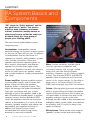
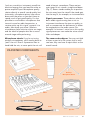
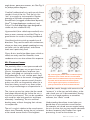
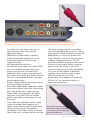
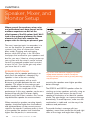
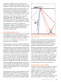
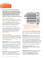
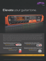
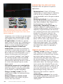
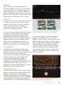
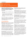
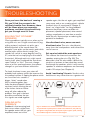
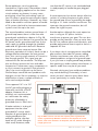
Contents
CHAPTER 1:
PA System Basics and Components
CHAPTER 6:
Choosing and Using the
Right Microphones
· Microphone Types
· Mic Placement and Usage
· Optimizing the Sound
· Cables and Connectors
Signal Processing
· Equalizer Types
· Shelving EQ Applications
· Parametric EQ Applications
· Graphic EQ Applications
· Reverb
· Limiter
· Compressor
· Other Effects
CHAPTER 3:
CHAPTER 7:
CHAPTER 2:
Balanced/Unbalanced Lines
and Connectors
· Impedance: No Worries!
· Cables
Amplifying Musical Instruments
· Mic Placement for Acoustic Sources
· Electronic Instruments
· Electric Guitar and Bass “Direct” Setups
· Singer/Songwriter Setup
CHAPTER 4:
Speaker, Mixer, and Monitor Setup
· Speaker Positioning
· Speakers and Walls
· Positioning the Mixer
· Positioning Performers or Presenters
· Positioning Monitors
· Tonal Setup
CHAPTER 5:
Mixer
· Inputs and Outputs
· Channel Strips
· Mixer Buses
· The Master Section
· Mono vs. Stereo
· The Importance of “Gain-Staging”
· Mixer Meets Computer
CHAPTER 8:
Sound Check
· “Ringing Out” the System
· Adjusting for Room Resonances
· Checking Sound Levels
CHAPTER 9:
Troubleshooting
· Solving “Out of Phase” Problems
· Dealing with Feedback
· Minimizing Distortion
· Reducing Hums and Buzzes
CHAPTER 10:
Glossary
Production Staff
Editor-in-Chief
Craig Anderton
Editors
John Krogh
Michael Parker
Advertising
Contact
Laurie Blondin
626-610-2434
Art Direction
and Layout
Patrick Wong
Photography
Theo Jemison
Joshua Merrill
Craig Anderton
www.m-audio.com
3
CHAPTER 1:
PA System Basics and
Components
“PA” stands for “Public Address,” and the
key word here is “public.” You want to
amplify a band, presenter, auctioneer,
lecturer, conference, worship service, or
other sound source so that the audio can
be heard clearly by a large group of
people—your listening public.
Fig. 1: The keyboardist is
using a boom mic stand to
go over the keyboard, while
the singer behind him is
using a straight,
vertical mic stand.
The most common public address system
components are:
Loudspeaker. Loudspeakers convert
electrical energy into acoustic energy—moving
air that we can hear with our ears. In addition
to loudspeakers that are like home hi-fi
speakers on steroids, public address systems
often include subwoofers. These are
speakers optimized to reproduce bass, as
bass requires more power and different
speaker construction than higher audio
frequencies. Speakers are built into cabinets,
which can often mount on speaker stands,
and include handles to simplify transportation
and setup.
Power amplifier. A power amplifier receives
incoming audio signals, and increases their
power so they can drive the speakers.
Amplifier power is measured in watts. The
higher the wattage, the louder the potential
levels you can achieve with your system,
although of course the speakers need to be
able to handle the available power. In modern,
compact systems like the M-Audio® GSR
series, the amplifiers are built into the same
cabinet as the speakers. As a result, all three
elements—speaker, amplifier, and cabinet—are
optimized to work together efficiently. In
addition, this kind of system is more
transportable (with fewer wiring issues)
because it’s more self-contained.
4
LIVE SOUND SURVIVAL GUIDE
Mixer. A mixer combines multiple signal
sources, typically microphones and
instrument outputs, into a single, unified
output that can then feed the power
amplifiers. However, not all situations require
a mixer. The M-Audio GSR10 and GSR12
speakers have microphone and instrument
inputs—so for simple setups, it’s possible to
feed a mic or instrument directly into the
GSR, and not require any other connections.
Cables. Although placing an amp and speaker
within a single cabinet eliminates the need to
connect these two elements with a cable, you
still need cables to connect the mixer to the
amplifier, and input signals to the mixer.
Although you don’t need to buy ultra-expensive
audiophile cables, quality cables are important
for reliability, and it’s crucial to always carry
spares as backup.
Microphones. These are the mirror image of
speakers, as they convert acoustical energy
(such as a vocalist or instrument sound) into
electrical energy that can feed the mixer or
power amplifier input. Microphone quality
relates directly to overall sound quality, but
fortunately, microphone prices have come
down over the years so you don’t have to
spend much to get good quality. It’s also
possible to use wireless microphones that
transmit sound as radio frequencies; a
receiver picks up this signal, converts it to
audio, then feeds your mixer. Wireless
microphones help minimize clutter on stage,
and are ideal for people who like to move
around stage while performing.
need to be put somewhere. There are two
main types of mic stands: straight and boom
(Fig. 1). Boom stands enable you to position
the mic away from the stand if the stand gets
into the way of, for example, an instrumentalist.
Microphone stands. If you’re not using
wireless microphones, you’ll need a place to
“park” the mic. Even if a presenter likes to
hand-hold the mic, at some point the mic will
The room and audience. You may not think
of them as part of a PA system, but as we’ll
see later, they can have a major effect on the
overall sound.
Signal processors. These devices alter the
basic audio signal coming from a mic or
instrument to enhance the tone or quality, as
well as compensate for deficiencies in either
the equipment or the audio source. For
example, if a lecturer’s voice has a thin quality,
signal processors can make the voice sound
fuller and deeper.
PA SYSTEM COMPONENTS
Microphone
Signal Processor
Desktop
Microphone Stand
Mixer
Cable
Speaker
www.m-audio.com
5
CHAPTER 2:
Choosing and Using the
Right Microphones
In the studio or on stage, the mic is the
first link in the audio chain. We’ll look at
which mic types work best for live use,
then describe how to get the best sound
from them.
MICROPHONE TYPES
No matter which mic you choose, two key
factors are ruggedness and directionality (the
ability to pick up a particular sound source
without picking up others).
Fig. 2: The mic on the left is
the M-Audio SoundCheck,
There are two popular mic types for PA
systems (Fig. 2).
an affordable dynamic
Dynamic microphones are physically rugged
and can handle high sound pressure sound
levels, so they’re the most common choice for
PA systems. They also resist noise from
handling, making them popular in hand-held
applications (e.g., vocalists). The tradeoff is that
the sound isn’t as refined as other technologies,
but live, these differences are negligible.
condenser mic that’s also
Condenser microphones are common for
recording due to their excellent frequency
response and ability to respond to transients
(rapid changes in level, as from percussion).
They’re more fragile than dynamic mics, and
most models need a power supply—either from
an internal battery, or from “phantom” power
that can be supplied by all but the least
expensive mixers (see Chapter 4 on Mixers).
However, condenser mics designed for live
use are getting more rugged, and with proper
care, can hold up to the rigors of the road. As
they’re sensitive to handling noise, they’re
usually mounted on mic stands.
There are two common condenser mic
types. Small-diaphragm mics are more
6
LIVE SOUND SURVIVAL GUIDE
microphone. The one on the
right is the Nova, a
from M-Audio.
sensitive, so they excel at reproducing
transients. Large-diaphragm mics tend to
give a “warmer” sound, and are often used
for vocals in the studio.
A third type of mic technology, the ribbon
microphone, is seldom used live due to fragility.
MIC PLACEMENT AND USAGE
Any mic needs to be placed so that it picks up
sound optimally—but to do that, you need to
know some mic basics.
Mic Directionality
This is crucial for live use, as you want mics to
pick up specific sounds and discriminate against
other sounds (e.g., you don’t want a vocal mic to
pick up instrument sounds on the same stage).
Different mics have different pickup patterns for
specific applications, sort of like cameras—some
“see” only a small part of what we can see with
our eyes, but there are also cameras with wide-
angle lenses, panorama cameras, etc. See Fig. 3
for pickup pattern diagrams.
Cardioid (unidirectional) mics pick up only those
sounds in front of the mic. Thus the mic can
“aim” at a vocalist or instrumentalist. Popular
examples of M-Audio microphones are the
SoundCheck (a rugged, unidirectional dynamic),
Nova® (a large-diaphragm condenser), and
Pulsar II (a small-diaphragm type designed for
studio use, but suitable for live).
Hypercardioid (also called supercardioid) mics
have an even narrower sound field. They’re a
good choice for vocalists fronting loud bands.
Omnidirectional mics pick up sounds from all
directions. They can be useful with conferences,
where you have many people speaking but may
not have a mic for each person, and volume
levels aren’t particularly loud.
Figure 8 mics tend to be ribbon types, which as
noted, are rarely used live. However, some
condenser mics can also achieve this response.
Mic Placement Issues
The proximity effect is most pronounced with
dynamic cardioid types—as you get closer to
the mic, the apparent bass response rises.
Singers with good mic technique use this to
their advantage: On soft, intimate parts they’ll
hold the mic close to the mouth, to exaggerate
the bass and give a warmer sound. Acoustic
guitars can also use the proximity effect for a
more bass-heavy sound. In any event, either
use it to your advantage or compensate for it.
The inverse square law states that the sound
level drops dramatically the further the mic is
from the sound source. This can be a problem
with vocalists who lack good mic technique,
alternately “swallowing” the mic and then
backing away, without changing their volume
to compensate.
The mic’s angle in relation to the sound source
affects tone. Generally, aiming the mic’s element
at the sound source results in the brightest
Fig. 3: The top polar pattern shows a cardioid response;
note how it rejects sounds from the rear. The middle
pattern shows an omnidirectional response, which picks
up sounds from all directions. The bottom pattern
shows a figure-eight response, so-called because it
picks up sounds from the front and back of the mic.
sound (be careful, though; with some mics the
“entrance” is at the top, and with others, at the
side—check your mic’s documentation). Having
the mic at an angle produces a somewhat
mellower, less “direct” sound.
Understanding these three issues helps you
decide how to mic particular sound sources.
For example, soft sound sources require having
the mic up close, but you may need to decrease
the bass response (see Chapter 6 on signal
processing, as well as the section on
www.m-audio.com
7
Fig. 4: A pop filter prevents wind noise and
plosives from getting into a mic, and also blocks
breath moisture, which can have negative
might be so loud it overloads a mixer’s mic
input. Enabling the pad switch will
minimize distortion.
effects on mic elements.
Reducing Feedback
Feedback occurs when a signal from the speaker
gets into the mic, and therefore gets re-amplified.
Fixing feedback involves several elements of any
PA system: Speaker placement, mixer control
settings, and mics. Using directional mics that
point away from speakers, and avoiding the
proximity effect are two ways to reduce the
possibility of feedback at the mic itself. For more
information, see Chapter 9 on Troubleshooting.
Dealing with “Thin” Sounds
Optimizing the Sound toward the end of this
chapter) to compensate for the proximity effect.
With louder sound sources like wind
instruments, you can back the mic away a bit,
and there won’t be major volume variations if
the player moves around a bit. When miking
something like a guitar amp, you have a lot of
latitude on mic placement—the standard is to
point it at the middle of the speaker in a
speaker cabinet, but different placements can
yield different tones.
OPTIMIZING THE SOUND
Now that you’ve chosen your mics and set them
up, here are several ways to optimize the sound.
Mic Switches
Mics often include switches for tailoring the
sound, such as:
If you’re using two mics with an instrument like
piano, you can run into phasing problems if
each mic picks up a different portion of the
sound wave. This can result in a “thin,” unnatural
sound. If your mixer has a Phase switch for each
channel, try flipping this for one of the mics in
the pair. If this solves the problem, fine.
Otherwise, for more information on how to solve
this problem, refer to Chapter 9.
Reducing Wind and Breath Noise
The rush of air from sounds like “b” and “p”
can produce nasty pops. Also, wind noise can
create similar problems. You can use a cover
made of acoustic foam that slips over the
mic’s head and reduces these sounds—or use
a clip-on nylon mesh screen filter between the
vocalist and the mic (Fig. 4).
Extending Microphone Life
· On/off (mute) switch. This is handy
Abused mics may continue to function, but
lose sound quality. Always store mics in their
protective cases.
·
CABLES AND CONNECTORS
·
when, for example, handing a mic from one
person to another, or briefly turning off the
mic if a sneeze or cough is imminent.
Low-cut filter. These reduce low-frequency
content. If a vocalist’s or lecturer’s “b” and
“p” sounds cause a loud “popping,” or the
proximity effect is a problem, turn the filter on.
Pad switch. This reduces the mic’s
sensitivity. For example, a loud guitar amp
8
LIVE SOUND SURVIVAL GUIDE
Cables connect the various PA elements,
providing a way for signals to get from one
place to another. In the next chapter, we’ll cover
how to choose the right cable, as well as get
the best performance out of your cables.
CHAPTER 3:
Balanced/Unbalanced
Lines and Connectors
Cables for unbalanced lines have two
conductors, while balanced lines have
three conductors (don’t confuse this with
typical stereo cables, which also have
three conductors; balanced lines are for
carrying a single, monophonic signal).
Balanced lines can help reject
interference from sources like fluorescent
light buzzes, hum, and even radio
frequencies from passing mobile
transmitters (e.g., taxis, CB radio)—as
long as they connect to inputs and
outputs whose circuitry is designed to
take advantage of balanced lines. This
technology is particularly useful with lowlevel signals, as the interference might be
almost as strong as the signal itself.
Unbalanced lines are more common, and
include guitar cords as well as most hi-fi
cables. Unbalanced cables don’t reject
interference as well, but they’re generally less
expensive, and work fine in applications with
strong signal levels.
The two different types of lines can use different
connectors. Fig. 5 shows an unbalanced 1/4”
phone plug; note that it has two sections, one
for each line. This is also called a TS type of plug
because it has a “tip” and a “sleeve” section.
As for jacks, you can’t tell whether 1/4” phone
jacks are designed for balanced or unbalanced
lines from the outside. However, most
equipment manufacturers will label their jacks
(Fig. 8) so you know what type they are. XLR
jacks (Fig. 9) are balanced; you can see three
holes for the three plug pins.
A relatively recent type of jack, the
combination jack (Fig. 10), gets its name
because it combines XLR and 1/4” phone jack
capabilities—you can insert either type of plug
(but of course, not both at the same time).
With 1/4” phone connections, the combo jack
can work with balanced or unbalanced lines.
Another unbalanced connector, the phono
connector (Fig. 11), is more common with
consumer gear. However, some PA mixers
include RCA phono jacks for one or two inputs
in case you need to interface with something
like a portable CD player. (Phono connectors
are also used for S/PDIF digital signals.)
Here are guidelines about which type of gear
uses which type of line and connector.
Microphones. Almost all mics for PA
applications use balanced lines and XLR
connectors.
Fig. 6 shows a balanced 1/4” phone plug.
These are called TRS (tip-ring-sleeve)
connectors because they have three sections:
The tip and sleeve (like a standard unbalanced
phone connector) but also, a third “ring”
section in between the tip and the sleeve.
Synthesizers and other electric
instruments. Many of these devices offer
balanced line outputs that work with balanced
or unbalanced lines. Unless the cable run is
very long or there are audible sources of
interference, unbalanced lines will work fine.
Fig. 7 shows an XLR plug, as used for
balanced connections. The three pins connect
to the three conductors.
Turntable preamps, portable CD players,
etc. These consumer devices typically use
unbalanced lines with RCA phono
www.m-audio.com
9
Fig. 6: A balanced (TRS) 1/4” phone plug. Note there are
three sections, separated by black insulating bands—the
tip, the ring, and the ground. These are also called stereo
plugs when used to carry two independent left and right
channel signals.
Fig. 5: An unbalanced 1/4” phone plug. Note the tip,
the black insulating band, and ground. The flare
toward the base of the jack provides a stronger grip
when inserted into a jack.
Fig. 7: An XLR
plug, as used for
balanced line
connections.
connections. Since cable runs are usually
short, unbalanced lines are not a problem.
Portable MP3 players. These use stereo
mini-jack and plug connectors, which resemble
1/4” phone types but are smaller (Fig. 12).
Most pro audio gear does not accept this type
of connector, so you if you want to use one,
you’ll likely need an adapter that converts the
stereo mini-jack output to two separate,
unbalanced lines, typically terminated in 1/4”
phone or phono plugs.
Electric guitar and bass. Almost all use
unbalanced lines.
Mixer inputs. The mic inputs will accept
balanced lines with XLR jacks. The line ins
usually accept either balanced or unbalanced
lines via 1/4” jacks, but some higher-end gear
uses XLR jacks for balanced line-level signals.
Powered speakers. Models like the M-Audio
GSR series powered speakers accept the linelevel signals coming from today’s mixers and
include combo jacks, so they can interface
with whatever connector your mixer uses.
IMPEDANCE: NO WORRIES!
With today’s PA systems, impedance (which,
to simplify greatly, represents the “friction”
Fig. 8: The M-Audio DMP3 preamp
has output jacks toward the left,
but looking at the jacks, you
wouldn’t know whether they’re
balanced or unbalanced. So,
they’re labeled as being balanced.
www.m-audio.com
11
Fig. 9: The XLR jack is the large, round
connector toward the left. Also note the red LED
to its lower left, which indicates that phantom
power to the mic is enabled.
Fig. 10: The combination XLR jack is toward the left, and accepts
both XLR and 1/4” phone plugs.
audio signals encounter at inputs and outputs,
and is measured in ohms) isn’t something you
need to know much about—just follow a few
basic guidelines.
Microphones. Almost all PA microphones have
a low-impedance output and generate low-level
signals. So, connect low-impedance mic outputs
to low-impedance mixer mic inputs (Chapter 4)
as these inputs are designed specifically to
accept low-level, low-impedance signals.
Synthesizers, turntable preamps,
portable music players, etc. These
invariably have low-impedance inputs and
generate high-level (“line-level”) signals.
Impedance matching is not an issue if you
simply plug their outputs into mixer inputs that
handle line levels.
Electric guitar and bass. These are special
cases, because the output impedances are too
high for mic inputs, while the signal levels are
too high for mic inputs but too low for line-level
inputs. Some mixers have special guitar inputs;
otherwise, if you plan to plug a guitar into a PA
12
LIVE SOUND SURVIVAL GUIDE
system directly, you’ll probably need to use a
preamp to match impedance and boost the
level. However, if the guitar goes through
various effects, a multi-effects processor, or a
pedalboard, these will almost certainly generate
enough level to feed line-level mixer inputs.
Powered speakers. Models like the M-Audio
GSR series aren’t very sensitive to impedance,
so simply plugging the mixer output into the
speaker’s input will do the job. With older, nonpowered speakers, the rules regarding
impedance are pretty simple too: Match the
speaker impedance with the same impedance
output on your powered mixer or power amp.
For example, if an amp has 4- and 8-ohm
outputs, and the speaker is rated at 8 ohms,
plug it into the 8-ohm output.
CABLES
Here are tips on the care and handling
of cables.
· Assess what kind of cables you need to
connect your various pieces of gear. Don’t
buy longer cables just because they’ll work
Fig. 11: The M-Audio Fast Track Pro audio interface offers balanced TRS 1/4” phone jack outputs, but note the
four RCA phono output connectors to the left of the TRS output jacks. The inset shows an RCA phono plug.
·
·
·
·
·
·
·
for shorter runs too—have a selection of
short and long cables, then use the
appropriate length.
Have plenty of spare cables as backup.
Cables are generally reliable, but can fail
(and always seem to fail at the most
inopportune time).
Use balanced lines with mics.
For relatively short cable runs—under 20-25
feet or so—unbalanced lines are fine for
outputs from musical instruments like
keyboards, direct outputs from guitar and
bass amps, and the like. But, there’s certainly
no harm in using balanced lines if the gear
accommodates them.
Always unplug cables by grasping the plug,
never by pulling on the wire.
Avoid sharp cable bends, stepping on cables,
rolling heavy objects over them, and running
them near power lines or heat sources.
Where cables are exposed to the public,
tape them to the floor with non-residue
gaffer’s tape. Make sure people can’t trip
over them.
Carry cable ties (available at office supply
stores) to bundle cables together for a
neater setup. However, don’t bundle cables
carrying strong signals (like speaker
connections) with cables carrying low-level
signals (like mics), as there may be crosstalk.
· The metal in plugs and jacks can oxidize
·
·
over time, degrading the connection. Squirt
some contact cleaner (available at stores like
Radio Shack, or a more pro product like
Caig’s DeoxIT) on the plug, then plug and
unplug a couple dozen times. This will
remove the oxidation and improve the contact.
Connect all your cables before turning on
power to your PA system. If you must
connect or disconnect a cable while power
is on, turn off the amplifier or powered
speakers, then turn them back on again
when all connections are made.
Always have some adapters on hand, like
XLR to 1/4”. You never know when to
expect the unexpected.
Fig. 12: This stereo mini-plug
looks like a smaller version of a
1/4” stereo or balanced plug—and
that’s exactly what it is.
www.m-audio.com
13
CHAPTER 4:
Speaker, Mixer, and
Monitor Setup
Where you put the speakers, mixer, mics,
and performers has a huge impact on the
audience experience as well as the
effectiveness of the PA system itself. We’ll
look at the optimum placement for these
elements, but first, let’s consider the
proper order for turning on pieces of gear.
The most important point to remember is to
turn on the amplifier (or powered speaker
systems) last, after all connections have
been made. Plugging and unplugging
devices while the system is on can make
loud pops that are bad for your speakers and
bad for your ears. Likewise, always power-up
your system with the mixer’s master volume
control (or powered speaker level controls)
at zero—full off. Turn up the gain only when
you know that all is well.
SPEAKER POSITIONING
The primary rule for speaker positioning is to
place (from the audience’s viewpoint) any
speakers in front of the mics used by
performers or presenters, with as much
distance as possible between the mics and
speakers. This allows for the maximum gain
before feedback. One exception is DJ setups if
a microphone is not a major part of the
performance. In this case, speakers can be on a
horizontal line with the DJ or even slightly
behind, and if the DJ has a wireless mic, he can
step behind the speaker for announcements.
When mounted on speaker mounting tripods,
speakers should be higher than the audience
and tightened down so they cannot move or
rotate on the tripods. If someone walks in front
of the speaker, the speaker itself should be
higher than the person; in some venues,
14
LIVE SOUND SURVIVAL GUIDE
Fig. 13: In a small auditorium, angling the speakers
slightly inward toward the audience can improve
coverage. You may even be able to get away with using
only one speaker.
mounting the speakers even higher provides
better coverage.
The GSR10 and GSR12 speakers allow for
stacking up to two speakers vertically, using an
interlock system that fastens the top of one
speaker to the bottom of an identical speaker
model. The extra height can improve coverage
dramatically. To avoid tip-overs, make sure the
combination is stable and out the way of the
audience and performers.
To provide the best coverage with two
speakers, mount them toward the left and right
sides of the stage, and angle them slightly
toward the middle—draw an imaginary line
down the middle of the audience, and aim the
speakers to a point about three-quarters of the
way toward the far end of the room (Fig. 13).
Note that high frequencies emanating from a
loudspeaker are highly directional, whereas
low frequencies can bend around objects in a
room. If everyone in the audience can see the
speaker(s), they’ll likely be able to hear the
high frequencies. This also means that
subwoofers (like the GSR18) do not need to
be raised, and in fact, will sound better if they
sit on the floor or the stage (which is fortunate,
as subwoofers are heavy). Furthermore,
special pole mounts are available for mounting
a GSR10 or GSR12 above the GSR18,
providing an optimized high-frequency/lowfrequency speaker pair.
SPEAKERS AND WALLS
The audience doesn’t hear only the sound from
the speakers, but sounds reflected off the
walls and other objects. If there’s a significant
time difference between these two sound
sources, music becomes less distinct, and
presenters less intelligible.
Sound travels at about one foot per millisecond
(a thousandth of a second, or ms). While delays
under about 30ms are generally not perceived
as objectionable, delays over 30ms produce an
echo effect. Ideally, for an audience member the
difference in distance between the speaker and
the nearest reflective hard surface (which will
produce the loudest reflection) will be 30 feet
or less. Of course this is not always possible,
but the closer you can come to this ideal, the
better. Also note that the longer the reflection
path, the weaker the sound. So even though a
reflection might be more than 30 feet away, if it
has to travel a considerable distance (especially
if there are absorptive surfaces in the room, like
people, clothing, drapes, etc.) it won’t have as
much influence.
Sounds bouncing off a side wall tend to be less
problematic than sounds bouncing off a wall
behind the speaker, or in front of it. Referring to
Fig. 14, person “A” in the back of the hall will
hear the direct sound from the speaker, and the
Fig. 14: Person “A” may actually hear better sound quality
than person “B,” who’s closer to the speaker, depending on
a variety of factors.
reflection from the back wall. This person will
hear reasonably good sound quality because
the difference between these two sound
sources will be less than 30 feet, the angled
sounds coming off the wall won’t be that
different in length than the direct sound, and the
rear reflection will be much weaker anyway. On
the other hand, person “B” will hear the sound
from the speaker, long side reflections from the
walls, and a reflection from the back of the
room—which may be a problem if the back wall
is hard and reflects a lot of the sound’s energy.
This is one reason why speakers are angled
toward the middle-to-rear of the audience, as
the more direct sound will be louder than the
reflections and minimize any echo effect.
POSITIONING THE MIXER
At professional concerts, the person mixing the
sound is usually stationed toward the centermiddle of the hall, in order to hear what the
audience hears. This is not always practical in
other situations, especially since long cable
runs (called “snakes”) are necessary to
connect the mixer to the mics on stage, as well
as to the speakers at the side of the stage.
www.m-audio.com
15
A common approach for smaller venues (e.g.,
conference rooms in convention centers) is to
position the mixer off to one side, fairly close to
one of the speakers. The person doing the
mixing will hear the direct speaker sound; while
this doesn’t take room reflections into account,
the balance among sound sources for those
hearing the direct speaker sound will be correct
(or at least, be what the mixer hears).
In situations where the person doing the mixing
should not be visible for aesthetic reasons (such
as plays), or there is no room in front of the
stage for a mixer, one option is to have the mixer
off to the side of the stage, just behind the edge
of a curtain. The mixer will need to rely on
headphones and during sound check, confirm
that what’s being heard in the headphones is
representative of what the audience is hearing.
POSITIONING PERFORMERS OR
PRESENTERS
As mentioned, mics should be behind the
speakers to minimize feedback. When
performers use mic stands, they can be
positioned in place. Wireless mics are more of
a problem, particularly with lead singers who
like to “work the crowd,” or motivational
speakers who roam the stage. These people
need to be told beforehand to avoid moving in
front of the speakers, and whoever is mixing
should watch them closely and reduce the
gain if it appears that their movement might
result in feedback. Hypercardioid mics work
well in this context, and the person should
speak or sing close to the mic so that the
voice’s level is much louder than any sound
that might be coming from the speakers.
put a “wedge” monitor speaker in front of a
performer, pointing up to them at a 45-degree
angle (Fig. 15). Using hypercardioid mics
minimizes pickup of the sound coming from
these speakers, and the volume levels needn’t
be high as the speakers are pointing directly at
the performer from a short distance away.
Both the GSR10 and GSR12 speakers can
function as wedge monitor speakers when laid
on their sides. The GSR10 is ideal for this
application due to its smaller size, making it
less obtrusive to the audience.
TONAL SETUP
Adjusting the overall tone to match a particular
venue can improve the sound quality
dramatically. One common solution is to use an
equalizer (either one built in to the mixer, or
added in the signal path between mixer and
amplifier), but the M-Audio GSR10 and GSR12
speakers take a simpler approach by offering
four “tuning” modes that optimize the speakers
for specific types of applications and rooms.
Normal mode is the standard listening mode,
with flat response. Hi-Fi gives more presence for
music playback in an application like a school
dance or when providing background music. DJ
mode boosts the lows and gives more definition,
thus providing a “DJ sound” even at relatively
low volumes.
Voice mode is optimized when plugging a mic
directly into the GSR10 and GSR12 for
conferences, boardroom meetings, seminars,
and other applications where all you really
need is an amplified voice (no music) and
aren’t using a mixer.
POSITIONING MONITORS
The performers will not hear themselves
accurately since they are standing behind the
speakers. For some people, like presenters,
this doesn’t really matter. For singers, it can be
crucial because they may not be able to stay
on pitch if they can’t hear themselves.
In-ear reference earphones, which resemble
earbuds, are generally considered to be an
optimum solution. Otherwise, it’s common to
Fig. 15: If leaned on their sides,
the GSR10 and GSR12 can
serve as floor wedge monitors.
www.m-audio.com
17
CHAPTER 5:
Mixers
The mixer is your PA’s traffic director—
signals enter from various sources, and
are routed to one or more sets of outputs
that feed the speakers. Mixers may look
daunting, but they consist primarily of
multiple, identical channels: Learn one
channel, and you’ve learned the others too.
INPUTS AND OUTPUTS
The main mixer specification is the number of
inputs and outputs. For example, an 8-in, 2-out
mixer can accept eight different signal
sources, and combine them into two outputs
(also called buses). These two outputs can
provide stereo (left and right) channels.
You can think of the input signal path as a
vertical, downward flow into the mixer, and the
bus (output signal path) as a horizontal flow
from left to right out of the mixer (Fig. 16).
Typical mixers have anywhere from four to
dozens of inputs.
CHANNEL STRIPS
Each mixer channel has its own channel strip
(also called an input module) for processing or
routing a signal before sending it to the output.
A basic channel strip (Fig. 17) includes some
or all of the following:
Input jack(s). This can be a low-impedance
XLR mic input, a line-level input for stronger
signals, both types of inputs with a selector
switch, a stereo signal input, or other, less
common options. Mixers often include
different inputs—a 16-input mixer might have
eight XLR mic inputs, and eight line-level
1/4” inputs.
Insert jack. This allows patching external
gear, such as particular equalizers or
compressors (see Chapter 6) into the mixer
channel’s signal path. To save space, the
18
LIVE SOUND SURVIVAL GUIDE
Fig. 16: Signals flow from the inputs through the
mixer channels, to the channel faders, then to the
panpots. At this point, the signals go to a master
stereo bus, which flows through the master faders,
then to the outputs.
insert jack is usually a TRS (tip-ring-sleeve)
type, and requires a special breakout cable to
feed a signal processor’s input and output.
Preamplifier. Intended to amplify low-level
signals (e.g., mic outputs), the preamp will
offer large amounts of gain, as set by a gain
control. If the channel strip also offers a line
input, the gain control will be bypassed, or
cover a different, more appropriate gain range.
Preamps help bring all external signals to the
same approximate level prior to being mixed
together with the faders (described later).
Phantom power switch. When on, this
sends +48V to an XLR mic input to power a
condenser mic.
Low-cut filter. Although not always included
in mixers, this reduces low frequencies to
minimize room rumble, mic “pops,” etc.
Similarly, a high-cut filter reduces high
frequencies to lessen sibilance and hiss.
Fig. 17: Here’s a typical channel strip,
from the M-Audio NRV10
mixer/interface. From top to bottom,
there’s an XLR mic input, a 1/4” line
input for balanced or unbalanced
lines (which you can use instead of
the XLR in), TRS insert jack, mic/line
switch to tailor the gain control
as pulling the fader all the way down. Use
mute switches to keep channels out of the mix
until right before they’re needed.
Panpot. With stereo mixers, this places the
input signal anywhere in the stereo field—from
full left to full right.
characteristics to the chosen input,
preamp gain control, three EQ
controls for high/mid/low
frequencies, two aux send controls
(one to a monitor out, one to the
onboard digital effects), pan control,
and level fader. Note the red clipping
indicator to the upper right of the
level fader, along with a yellow light
to indicate when a channel is muted,
as chosen by the Mute switch at the
bottom of the channel strip.
Clipping indicator. This is
usually an LED that lights if
the signal exceeds the
preamp’s available dynamic
range, which means you
should turn down the
preamp gain. Some inputs
also have an “activity” LED
that lights if there’s a signal
present (which verifies that
a signal is reaching the
mixer channel). Another
variation combines both
functions into a bi-color
LED that glows green to
indicate an activity, and red
to indicate overload.
Equalizer. This is a type of
tone control; see Chapter 6.
Send control. See the
section on Mixer Buses.
Solo switch. Soloing a
channel mutes all other input
modules. This is useful for
hearing exactly what’s happening in a channel
without being distracted by the other channels.
Mute switch. Muting a channel is the same
Fader. This sets the level of the channel in
relation to the other channels. It may be a
linear slider (Fig. 18), or a rotary control.
MIXER BUSES
Basic mixers have two output buses. More
advanced models have several buses (called
send or auxiliary buses), and you can set up
different mixes on these different buses
using send or aux level controls. These “pick
off” part of a channel strip’s signal, and send
it to a bus in the same way a fader regulates
the level going to the master stereo output
(Fig. 19).
One common use for a mixed bus output is to
set up a separate mix for singers. This is
because if the singers can hear themselves
coming from the main speakers, then that
sound is probably getting into their mics,
which encourages feedback. But setting up
the mics behind the speakers to minimize
feedback makes it difficult for the singers to
hear themselves, making it tough to stay on
pitch. As mentioned previously, one solution is
to provide the singers with reference
earphones. A separate mix can be set up
specifically for the singer using an auxiliary
bus, perhaps with vocals and melodic
instruments up loud, and drums turned down.
This aux bus output feeds a separate
headphone amp, which drives the reference
earphones. Thus the singers can hear
themselves without having the monitor signal
get into their mics.
Another bus application is to provide a master
volume control for several individual channels.
For example, suppose you’re mixing a church
choir with multiple mics. You can send a signal
from each mic to a bus, turn down the mic
channel faders, then return the bus output to a
www.m-audio.com
19
Fig. 18: Linear faders are very easy to adjust, particularly because you can move more than one at a
time. These eight linear faders are part of the Avid 003 interface for Pro Tools recording software.
mixer input or send (aux) return input (Fig. 20)
to blend it back in with the main output. Use
the send controls to balance each mic
perfectly, then if you want to raise or lower the
entire choir, use the mixer input level or send
return control rather than adjusting each send
control individually.
Send controls usually have a pre/post switch to
pick up the pre-channel fader signal (so the level
remains constant regardless of the fader setting)
or post-channel fader, so that pulling down the
fader pulls down the send to the bus as well.
Each mixer has its own way of sending signals
to buses. If space is tight and there are lots of
buses, a channel might have a send control
along with switches that route the send control
to a particular bus (or buses).
THE MASTER SECTION
A mixer’s master section includes “global”
controls, such as:
Master output control. This varies the
mixer’s overall output level.
Send bus master output controls. While
not present on all mixers, these affect the
overall level of the bus they control. In the
example of the singer listening through
20
LIVE SOUND SURVIVAL GUIDE
reference earphones, the bus master
control would adjust the level going to the
reference earphones.
Bus return controls. In the choir application
mentioned above, you may not need to use
up a mixer input for the bus return, as there
may be some “return” inputs specifically for
this purpose. These will be line level and
generally not offer all the options of a typical
channel strip, but usually include a level
control. They can also be used as extra
inputs in a pinch.
Output meters. Most mixers have at least an
output meter, and high-end mixers might
include meters for individual channels. A
typical meter will consist of 10 or more LEDs,
and use different colors to differentiate among
ranges of levels (green for normal, yellow for
close to overload, and red for overload). Avoid
letting the signal go into the red zone, as this
can lead to distortion.
Headphone output. Most mixers have a
headphone jack with an associated level control
that’s independent of the main output. This
means you can turn down the output so the
audience doesn’t hear anything, yet listen to the
various channels on headphones to make sure
everything is working properly.
MONO VS. STEREO
In most venues, mono is preferable so everyone
hears the same sound. With stereo, some people
will be in the “sweet spot,” while others will hear
mostly the left or right channel. To create a mono
mix with a stereo mixer, move all panpots to the
center position.
THE IMPORTANCE OF
“GAIN-STAGING”
This is the process of setting levels properly—
not too high, which can lead to distortion, and
not low, which can lead to hiss. There are
three main places to adjust levels in a mixer;
here’s how to set them.
· Preamp gain. Set this for the maximum
·
·
level short of distortion (i.e., just below where
the clip indicator lights). It’s acceptable if
the clip indicator lights briefly and very
rarely; otherwise, reduce the gain.
Master output. This will usually be
calibrated in dB. 0 dB indicates that it is
neither adding gain nor attenuating the
signal. Negative values indicate attenuation,
and positive values indicate gain. When
starting a mix, set it at around –3 dB. Mixers
generally have output meters that show the
overall level leaving the mixer.
Channel faders. Set these so that during
musical peaks, the output meters peak at
around –3 dB. If you need to increase the
level a bit as the venue fills up, no problem—
simply turn the master output to 0, or even a
little bit higher. If you need to go much
higher than 0, turn up the GSR series
speaker level controls.
Fig. 19: The dark blue lines indicate signals going through a
channel strip. The light blue lines show how signals come
off the channel strip audio into knobs, which regulate the
output going to the mixer’s monitor bus. The yellow lines
indicate a second send of sends, which feed the mixer’s
internal effects (e.g., reverb and the like).
MIXER MEETS COMPUTER
Some mixers, like the M-Audio NRV10, include
a computer interface that allows you to send
audio into a computer as well as to your
speakers. If the computer is equipped with
recording software, then it’s possible to
simultaneously record the live concert,
conference, service, etc. Although computerbased recording is beyond the scope of this
publication, it’s important to realize that there’s
the potential to add recording to your live
performance if you choose the correct mixer.
Fig. 20: The signals from several channels, for example
multiple mics from a choir, go to Aux Send bus 1.
Returning its output to a mixer input (in this case, the Line
In 7/8 channel) lets you use the Line In 7/8 fader to alter
the level of all mics together, without changing the
balance of the individual mics.
www.m-audio.com
21
CHAPTER 6:
Signal Processing
There are several ways to improve the
sound of your PA system, both on
individual channels and the overall
output, by using signal processors. Think
of these as the “spices” that bring out
the best in the signal sources feeding the
PA. But to use them effectively, you need
to understand how they work.
EQUALIZER TYPES
An equalizer (EQ) is a tone control that helps
shape a sound’s tonal quality. Thin voices can
be made fuller, “muddy” sounds made clearer,
and you can even use equalization to match
your PA’s sonic character to specific venues.
As mentioned previously, you’ll usually find
equalizers in mixer channel strips. However
there are many different types, from simple to
complex. Here’s a summary.
Shelving EQ
This is like the bass or treble control on a
typical hi-fi system. It gets its name because
it creates a “shelf” in the frequency response
(Fig. 21). A treble (or “high”) shelving
equalizer boosts or cuts high frequencies,
whereas a bass (or “low”) shelving equalizer
boosts or cuts low frequencies. Even budget
mixers usually include treble and bass
shelving EQ.
Parametric EQ
The response is different compared to shelving
equalizers, as it creates a peak (or notch) at a
specific frequency (Fig. 22). A parametric EQ
has three controls.
· Boost/cut. Also called Gain, this
determines the amount of the peak (boost)
or depth of the notch (cut).
22
LIVE SOUND SURVIVAL GUIDE
· Frequency. This sets the frequency at which
the boost or cut occurs.
· Bandwidth. Also called Q or resonance, this
specifies the range of frequencies affected
by the boost/cut control—from narrow to wide.
Quasi-Parametric EQ
This is like a standard parametric, but the
bandwidth is fixed instead of variable.
Graphic EQ
This has multiple sliders—anywhere from three to
dozens—with each slider determining the boost
or cut amount at a specific, fixed frequency (Fig.
23). It gets its name because the sliders’
physical positions show a rough approximation
of the frequency response. Graphic equalizers
are seldom part of a mixer’s channel strip, but
instead are included in the mixer’s master
controls to shape the overall output.
Multi-Stage EQ
Sophisticated mixers often combine multiple
equalization stages. For example, a high-end
mixer might have a four-stage EQ that
combines a bass shelving EQ, treble shelving
EQ, and two parametric stages. This allows for
versatile equalization. Even relatively low-cost
mixer channel strips may include three-stage
equalizers with high and low shelving, and a
parametric or quasi-parametric stage.
SHELVING EQ APPLICATIONS
Shelving EQs are best for broad, general
changes. However, you need to be careful in
situations involving microphones, as too much
added bass or treble can lead to feedback.
· Audience compensation. People and
clothing absorb sound, particularly high
PARAMETRIC EQ APPLICATIONS
Parametric EQs are optimum for precise
applications.
· Reducing hum. If there’s AC power-
·
·
Fig. 21: Shelving filter response. There is a high-frequency
boost, and low-frequency cut. The name “shelf” comes
from the fact that after the response rises or falls, it levels
off into a straight line.
·
·
·
·
·
frequencies. So as a room fills up, the overall
sound might seem somewhat duller. A slight
high-frequency boost at the output can help.
DJ applications. DJ audiences typically
expect more bass than, say, a conference or
acoustic music concert. Boosting the bass
results in a more crowd-pleasing sound.
Making presenters sound more
authoritative. Conferences and lectures
usually don’t require high volume levels, so
you can get away with greater bass or treble
boosts than you could compared to, say, a
concert. Assuming any mics have wind
filters to minimize “popping” (see Chapter
2), and their low-pass filters are enabled,
you can make the presenter sound more
authoritative by boosting the bass a little on
his or her mixer channel strip for a fuller,
bigger sound.
Increasing a presenter’s intelligibility.
If people in the back row can’t understand
what a presenter is saying, boosting treble
to some extent can help intelligibility.
Fixing a “muddy” sound. If the PA’s
sound seems muddy, try reducing the bass
at the output.
Fixing a strident, or harsh, sound.
Reducing treble at the output can give a
warmer, less harsh timbre.
24
LIVE SOUND SURVIVAL GUIDE
related hum in a channel, dial in a frequency
of 60 Hz (50 Hz in Europe). Set a narrow
(sharp) bandwidth, and cut the gain to reduce
the hum.
Reducing feedback. It’s a tricky to get
this right, but parametric EQ can sometimes
help reduce feedback. See Chapter 9 on
Troubleshooting for more details.
Separating “competing” sounds. For
example, suppose a singer/songwriter is
singing and playing guitar. Part of the guitar’s
frequency range will overlap with the vocal,
thus competing with the vocal sound. A fairly
broad cut on the guitar channel in the
vocalist’s range gives more space to the
vocal. The exact frequency to cut depends
on the singer; a bass or baritone can go
below 100 Hz, while a high soprano can hit
notes at around 1,200 Hz (with overtones in
either case going higher). Thus, consider
cutting the guitar starting around 500 Hz,
then adjust up or down as required by
the singer.
GRAPHIC EQ APPLICATIONS
· “Tuning” a room. A room is essentially a
·
filter; a space with thick drapes, carpets,
and wood chairs will absorb more sounds—
particularly higher frequencies—than a
concrete room with metal chairs, which will
be extremely bright. There will also be
resonances that boost some frequencies,
and reduce others. By listening to a known
music source, like a favorite CD, you can
adjust the graphic equalizer’s faders for the
most accurate sound. This will change as
you move around the room, so try for a
good average setting rather than
optimizing the sound for a specific
“sweet spot.”
General timbre changes. You can also
use a graphic equalizer to create the type of
timbral changes described earlier for
shelving EQ.
REVERB
Some PA mixers include reverberation to
simulate the effect of being in a concert hall or
large room. While this can sound impressive,
most pros turn it off as the PA is already in a
room, so adding reverb usually results in a less
distinct sound. The same is true for effects like
delay, echo, and “chorusing.” Less is more!
LIMITER
A limiter is an electronic circuit that acts like
a motor’s governor—it won’t let the sound
exceed a certain level. If a mixer includes a
limiter, it will usually be at the output
(although some high-end mixers include
limiters on individual channels).
A limiter will have an indicator that shows when
limiting occurs, which means the signal level
(and therefore the dynamic range) is being
restricted. You don’t want this to light very
often; a limiter is more of a “safety valve.” If this
light illuminates a lot, you’ll probably need to
reduce the overall output level control. If it
lights a lot on channel strips, then you’ll likely
need to reduce the amount of channel gain.
COMPRESSOR
A compressor also reduces dynamics but
unlike a limiter, reduces peaks and amplifies
lower-level signals to maintain a more constant
level. The most important controls are
threshold and ratio. Lower thresholds amplify
low-level signals more, while higher ratios
reduce high-level peaks more. While
compressors can help with presenters at
conferences where noise levels aren’t too high,
amplifying low-level signals with musical
ensembles can encourage feedback. For most
applications, leave compression off.
Fig. 22: Parametric filter response. A parametric filter can
provide a peak or a notch in the frequency response.
to create new types of sounds, and theater
groups can employ effects for tricks like
making voices sound as if they’re coming from
a different dimension. Mixers may also feature
built-in flanging (which imparts a “whooshing”
character to the sound), tremolo (a rapid,
cyclic fluctuation in level), delay (also called
echo, which produces the “shouting ‘hello’
into a canyon” effect), and chorusing, which
makes an individual instrument sound more
like an ensemble.
OTHER EFFECTS
The above are common effects for PA systems,
and are intended mainly to optimize the sound.
However, some mixers (like the M-Audio
NRV10) include effects that are more properly
considered “special effects.” While it’s doubtful
you’d use these in a conference or worship
situation, DJs can use special effects artistically
Fig. 23: A graphic EQ gets its name because the sliders
draw a “graph” of the frequency response.
www.m-audio.com
25
CHAPTER 7:
Amplifying
Musical Instruments
Compared to amplifying voice, the
process of sending instruments through
a PA system can be more complex. There
are two main options for amplifying
instruments:
· Mic acoustic sources, and feed the mic out
into a mixer.
· Patch a direct electrical signal from electrical
sound sources, such as electric guitar,
synthesizer, electronic drums, and drum
machines, etc. through patch cords into the
PA system.
Let’s consider miking first. As explained in the
chapter on microphones, the microphone type
and placement are the most important factors
in sound quality. So, let’s relate these to
various miking situations.
MIC PLACEMENT FOR
ACOUSTIC SOURCES
Vocals. While there are several recommended
“best” ways for singers to use a mic (holding it
away, holding it close, singing across it,
singing above it, singing into it, or a
combination of these as needed to emphasize
or de-emphasize specific aspects of the song),
every person’s voice requires a different
technique because every voice is different. For
many voices, condenser mics sound best; for
others, a dynamic mic gives the right sound.
Also, refer to the chapter on Setup for tips on
how to avoid feedback when miking vocalists.
Acoustic guitar. It may not be necessary to
use a mic, as many acoustic guitars have
pickups and onboard preamps that feed the
output directly into a mixer. If that isn’t an option,
the mic of choice is generally a condenser type
pointed between the sound hole and the bridge.
26
LIVE SOUND SURVIVAL GUIDE
Pointing directly at the sound hole can give a
“boomy” effect, while pointing directly at the
bridge often sounds “thin.”
Harmony vocals. Mic placement tends to be
further away from harmony singers than lead
singers, especially if two or more singers are
sharing a mic. This is also a situation where
subtle angling can differentiate the background
voices from the lead vocal.
Wind instruments. Use a dynamic mic to
cope with the high sound pressure level, and
back it off a foot or so from the instrument
being miked. With sax, the mic is generally a
few inches above the bell, and pointing
straight at the sax.
Piano. Open up the lid and use two condenser
mics, one pointing at the high strings, the other
pointing toward the lower mid/bass strings.
Make sure both are far enough away from the
hammers to avoid picking up the “thunk” when
they hit the strings.
Drums. There are several approaches to
miking drums, from having a forest of mics
covering every drum to a more minimalist
approach. Less is often more, and many
people mic drums successfully with just three
or four mics: a dynamic mic for the kick (either
just outside the head, or inside the drum), a
condenser between the snare and high-hat to
pick them up, an overhead condenser mic
above the drummer’s shoulder (pointing down
toward the toms and angled away from the
cymbals), and perhaps one or two room mics.
However, optimum placement depends on the
drum set, the desired prominence of different
drum sounds in the mix, the drummer’s
individual setup, etc.
Guitar and bass amps. Many amps now
include electrical direct outputs designed
specifically for feeding mixers and PA systems.
If you can, use these to keep your life simple!
But if that’s not possible, with a single-speaker
cabinet, point a dynamic mic at the center of
the speaker, a few inches away from the grille
cloth, or move the mic more toward the edge
of the speaker for a thinner, “tighter” sound. If
the cabinet has multiple speakers, try miking
just one. Also remember that when miked, a
small, low-power amp can sound just as big as
a stack of amps—without causing leakage
problems into other mics.
ELECTRONIC INSTRUMENTS
This category includes synthesizers, electronic
drums, stage pianos, drum machines, and the
like. These instruments typically produce linelevel, unbalanced signals, and can plug directly
into a suitable mixer channel input. They often
include onboard signal processors, so they get
their “sound” before going into the PA mixer,
and require no adjustments other than level.
Some players with extensive stage setups
(e.g., a keyboard player with multiple
keyboards, each with its own set of outputs)
might also use a submixer. A submixer is
conceptually like a standard mixer, but is
usually designed to mix several line-level
inputs, eliminating the need for mic preamps,
extensive EQ, and so on. Once the player
achieves the desired instrumental balance with
the submixer, then its master stereo output can
be sent to the main PA mixer.
addition to live performance applications,
Eleven Rack doubles as a computer interface
for Pro Tools LE® recording software.) Setup
is easy, as you simply plug the guitar into the
Eleven Rack input, and plug the outputs into
your PA system.
Another option is loading amp modeling and
effects software (such as Avid Eleven) into a
laptop computer or even one of the more
powerful netbooks. This requires an audio
interface that connects to the computer’s USB
port, FireWire port, or card slot (e.g., PCMCIA
or ExpressCard) to provide physical audio
inputs and outputs. Like Eleven Rack, the
guitar plugs into the input, and the outputs go
to the main PA mixer. Note that the audio
interface must have an input that’s designed
specifically to accommodate guitar.
Setups for electric bass are similar.
SINGER/SONGWRITER SETUP
You can insert a microphone or line-level input
into a powered speaker such as the GSR10
and GSR12, so having two of these speakers is
ideal for a simple, highly portable singer/
songwriter setup. The mic goes into one
speaker’s mic input, while the output from an
electric piano, synthesizer, or preamp output
from an acoustic guitar can go into the other
speaker’s line-level input. This eliminates the
need for a mixer, and each can have its level
adjusted independently. Note: This is a situation
where the GSR tone options can make a huge
difference to the overall sound—try them all.
ELECTRIC GUITAR AND
BASS “DIRECT” SETUPS
Carting around a big amp and lots of signal
processors can get pretty tiresome, so many
guitarists downsize their setups to compact
digital processors. These digital processors
emulate the sounds of effects, amps, and even
particular mikings of those amps.
A good example is the Avid® Eleven® Rack.
It includes a variety of amp, effects, and mic
models, making it possible to get a complete
guitar sound in a single, portable box. (In
www.m-audio.com
27
CHAPTER 8:
Sound Check
Now that everything is set up, it’s time to
test out the system and make sure
everything works and sounds as expected.
“RINGING OUT” THE SYSTEM
The optimum situation is to check out the
sound with the performers or presenters who
will be playing through the system. However,
this isn’t always possible, so you may need to
set up hours beforehand when the rest of the
people aren’t around.
Many sound engineers bring a portable CD
player or other portable music player with
music they know very well, like a favorite CD,
and play that through the system after setup to
get a rough idea of the system’s performance.
You can use this music to check for several
sonic qualities.
Coverage. While the music is playing, walk
around the room. Ideally, the sound should be
identical wherever you are, but this is seldom
the case. You may need to change the speaker
angle and/or height somewhat to obtain the
most uniform coverage.
With the M-Audio GSR series speakers, it’s
possible to daisy-chain up to three speaker
cabinets (Fig. 24). This provides many
additional speaker placement options. For
example, you may get better coverage by
stacking a speaker on top of another
speaker, or by placing the two side by side—
experiment to determine which is best, as
acoustics vary considerably from room
to room.
Placement is particularly important for high
frequencies. As you walk around the room,
make sure that everyone has a straight line of
sight with the speakers (Fig. 25). If not, angling
multiple speakers somewhat outward or
28
LIVE SOUND SURVIVAL GUIDE
Fig. 24: The GSR series speakers include a “Thru” jack that
can pass the input signal from one GSR speaker to another
GSR speaker’s input.
inward may give better coverage for a larger
segment of the audience.
If the bass from the subwoofer seems weak in
some spots, place the back of the subwoofer
against the wall, or even at the corner of two
walls. Any sound coming from the
subwoofer’s back bounces off the wall,
reinforcing the main bass signal. Although not
necessarily a common technique, some sound
engineers diffuse the bass sound more by
pointing the subwoofer front toward a corner.
This can increase the apparent amount of
bass, as well as cause the wall to vibrate,
which creates additional bass.
Tone. As mentioned previously, the tone can
change dramatically depending on the number
of people in a room. Therefore, when “ringing
out” a PA (a term pros use to describe the
sound check process), you mainly need to
analyze the room’s character so that you can
make adjustments later. For example, if the room
has really hard surfaces, the PA may sound a
little bright during sound check but if the room
fills up, then some of the highs will be
absorbed. It’s also worth trying the different
tone options in the GSR series speakers
(Normal, Hi-Fi, DJ, and Voice—see Fig. 26) as
you may find that one option gives a better
overall sound for a particular room than another.
necessary, you may want to try yet another
change and A-B the new sound with the
winner of the previous A-B comparison.
ADJUSTING FOR ROOM RESONANCES
As mentioned in the Signal Processing chapter,
some mixers have graphic equalizers at the
outputs. These make it easier to “tune” a room,
but proper adjustment requires some experience.
When you listen back to a CD you know well,
analyze whether any parts of the frequency
spectrum sound different than normal. For
example, if the upper midrange sounds harsh,
there may be a room resonance that accents
this part of the spectrum. Try bringing down a
graphic EQ slider in the 3–5 kHz range, and
listen for whether that makes a smoother overall
response. Conversely, if there are lots of soft
surfaces, then part of the midrange may sound
attenuated, which can make presenters sound
less distinct. In this case, a slight uppermidrange boost might solve the problem.
CHECKING SOUND LEVELS
Fig. 25: Pole-mounting a speaker on top of the woofer
can often provide better high-frequency coverage for
your audience.
Some areas have ordinances that govern the
maximum sound level for particular venues. To
make sure you are in compliance, use a
sound level meter. These devices have a
calibrated microphone and meter that shows
the level being produced at the location
where you’re checking levels. Sound level
meters are available from electronics stores
like Radio Shack, although there are also
iPhone and iPod Touch apps that provide
sound level metering.
If a room has a lot of soft surfaces—curtains,
plush seats, a packed house, etc.—then you may
find that the Hi-Fi setting gives a more balanced
sound than the Normal setting.
Veterans will tell you experimentation is key,
and it is. However, be careful. Switching from
one tone to another may sound great because
it’s a change that sounds fresh, not necessarily
because it’s better. When you make any
change, live with it for a while, then switch
back to how it was originally. Do this a couple
times to choose the “winner.” Then if
30
LIVE SOUND SURVIVAL GUIDE
Fig. 26: The GSR series’ Tone switch tailors the speaker’s
response to different environments.
CHAPTER 9:
TROUBLESHOOTING
Once you learn the basics of running a
PA, you’ll find the process to be
relatively trouble-free. However, there
will be times when you encounter
problems, and these tips should help
get you through most of them.
SOLVING “OUT OF PHASE”
PROBLEMS
Phasing problems typically occur when you’re
using two mics on a single sound source (e.g.,
miking a piano), and each mic picks up a
different portion of the sound wave. For
example, if one picks up the wave’s peak while
another picks up the wave’s trough, the
sounds will cancel to some degree (see Fig.
27; note that we’re simplifying for the sake of
illustration). Although each mic might sound
fine by itself, when combined the sound can
seem “hollow” or “thin.” The sonic change
when a jet flies overhead comes from phase
changes as you hear different reflections.
To check for phase issues, your mixer will
probably have a phase switch that reverses the
mic preamp’s phase. If flipping the phase switch
on one of two mics creates a
bigger, “fatter” sound when
they’re mixed together, then
leave the phase flipped. If there’s
no phase switch, moving the mic
a few inches closer or further
away will often reduce the
problem. Your goal is the best
possible sound when the two
mic signals are mixed together.
speaker again, hits the mic again, gets amplified
some more, and so on—creating what’s called a
feedback loop. As mentioned in Chapter 2,
there’s no “magic bullet” for fixing feedback
because the primary cause could be mic
placement, speaker placement, mixer control
settings, equalization, or even how a vocalist
holds the mic. Here are tips on reducing the
potential for feedback.
Use directional mics; never use omnidirectional mics. The mics should point
away from the loudspeakers and toward the
sound source.
Set up mics behind the main speakers.
This reduces the chance of sound from the
speakers entering the mics (Fig. 28). The
downside is that this also makes it difficult for
vocalists or lecturers to hear what they sound
like through the speakers, which is why monitor
speakers or reference earphones are commonly
used in PA setups (see Chapter 4).
Avoid “swallowing” the mic. Vocalists who
hold the mic very close often run a greater risk
DEALING WITH
FEEDBACK
Feedback is that annoying howl
that occurs when a signal from
the speaker enters the mic, gets
amplified, comes out of the
Fig. 27: Sound waves emanate from the sound source, and two mics
are positioned to pick up these sound waves. However, one picks up
the signal’s trough while the other picks up the signal’s peak, causing
the combined signal to cancel to some degree.
www.m-audio.com
31
Fig. 28: Top view of a stage setup. The main speakers face the
audience, with the performers and microphones set up behind the
main speakers. Additional monitor speakers face the performers so
they can hear themselves.
of feedback than if the mic is an inch or two
away. This is because the “proximity effect”
increases the amount of bass, which
encourages feedback in the bass frequencies.
Try adjusting the equalization. When
feedback starts, it will be at a specific
frequency. Solo each channel to find out which
one is triggering the feedback. Set the EQ for
a steep notch, then sweep the frequency
control until you find the frequency that
minimizes the feedback. While this may affect
the timbre of the sound going through that
channel, the reduced feedback may be worth
it. You may even be able to find another
feedback frequency on another channel,
reduce that, and have even more level before
feedback occurs. If the feedback seems to
occur in all channels, you may need to adjust
EQ at the mixer output. A graphic equalizer will
likely not allow for fine enough adjustment
compared to a parametric equalizer, but if
you’re lucky, the feedback frequency might
correspond to a graphic EQ filter frequency.
MINIMIZING DISTORTION
Distortion can occur in several places in the
system (see the section on Gain-Staging in
Chapter 5). First, check to see if any clipping
indicators light when the distortion occurs. If
32
LIVE SOUND SURVIVAL GUIDE
the indicator relates to a preamp, reduce the
preamp gain. If the indicator relates to the overall
system (e.g., the clipping indicator on a power
amp lights), then you need to reduce the master
volume or all the faders feeding the master output.
Granted the system won’t be as loud, but a softer
sound is a better option than a distorted one.
Second, distortion may be occurring in the
sound source itself. A damaged mic, for
example (e.g., it’s been dropped a couple times)
may have a fuzzy, distorted sound. Distortion—
intentional or unintentional—can also happen in
something like an instrument amplifier.
REDUCING HUMS AND BUZZES
Hums and buzzes are generally from one of
two sources.
The first is lighting dimmers or fluorescent
lights that generate interference. Mic preamps,
cables, guitar pickups, and other sensitive or
high-gain circuits can easily pick up this
interference. It’s simple to test for if this is the
problem: Turn off the lights and see if the
problem goes away. If the problem relates to
dimmers, turning the dimmer all the way up or
down will usually solve the problem.
Incandescent bulbs that don’t use dimmers are
least problematic.
Some appliances can also generate
interference. If lights aren’t the problem, check
whether unplugging appliances on the same
circuit reduces any buzzes. In many cases,
purchasing a line filter and making it part of
your PA setup is good insurance against these
types of buzzes and hums. However, any filters
need to be rated for sufficient power to handle
a PA system—the kind for home entertainment
systems won’t be up to the task.
sure that the AC source is not overloaded and
is rated properly to handle the gear plugged
into it.
The second problem involves ground loops. A
ground loop means there is more than one
ground path available to a device. In Fig. 29,
one path goes from device A to ground via the
AC power cord’s ground terminal, but A also
sees a path to ground through the shielded
cable and AC ground of device B. Because
ground wires have some resistance (the
electronic equivalent of friction), there can be a
voltage difference between the two ground
lines, thus causing small amounts of current to
flow through ground. This signal may get
induced into the hot conductor. The loop can
also act like an antenna for hum and radio
frequencies. Furthermore, many components in
a circuit connect to ground. If that ground is
“dirty,” the circuit might pick up the noise.
Ground loops cause the most problems with
high-gain circuits like mic preamps, as massive
amplification of even a couple millivolts of
noise can be objectionable.
Another option—although the most expensive
one—is using an AC power isolation
transformer to power your gear. This can also
provide ancillary benefits: clean up noise from
the AC line, reduce spikes and transients, and
provide performance almost equal to that of a
separate AC line.
A more expensive, but almost always effective,
solution is isolating the piece of gear where
the ground loop occurs by patching the audio
through a 1:1 audio isolation transformer. This
interrupts the ground connection, but still
allows the signal to pass.
If you have a lot of microprocessor-controlled
gear and less-than-ideal AC power, adding
isolation transformers can solve various ACrelated problems and get rid of ground loops.
If you just have a simple ground loop problem,
then patching in audio isolation transformers in
specific audio lines may be all you need.
Granted, solving any hum and buzz problems
may sound daunting. Fortunately, in most
cases you won’t have to worry about these
issues, particularly in smaller setups.
One supposed “fix” is to “lift”
the AC ground by plugging a
three-wire cord into a 3-to-2
adapter. However, this is
definitely not recommended
as it eliminates the safety
protection afforded by a
grounded chassis. Don’t do it.
A better solution is to plug all
equipment into the same
grounded AC source, which
attaches all ground leads to a
single ground point (for
example, a barrier strip that
feeds an AC outlet through a
short cord). However, make
Fig. 29: When a device can take two separate paths to ground, this
creates a ground loop. Whether it matters or not depends on several
factors, such as the “dirtiness” of AC power, and also, whether the device
is high-gain or not.
www.m-audio.com
33
CHAPTER 10:
GLOSSARY
Amplifier
A device with an input that receives weak
electrical signals, makes them stronger, then
sends them to an output suitable for driving
loudspeakers. Note that while amplifiers are
available as separate devices, they are often
built into speaker cabinets or mixers as a
matter of convenience.
Auxiliary Send
See Send Bus.
Cable
Wire that has connectors on both ends, and is
designed to interconnect pieces of gear.
Clipping
The phenomenon that occurs when an input
signal exceeds the headroom (dynamic range)
that a system can handle, thus distorting the
waveform because it cannot be reproduced
accurately.
Clipping Indicator
A light, typically found on mixer channels and
amplifier outputs, that indicates when a
signal exceeds the maximum available
headroom. When a clipping indicator lights,
you need to turn down the level in the
system (either at individual mixer channels, or
the master level if clipping occurs in the
power amplifier).
Distortion
What happens when a waveform cannot be
reproduced properly for one reason or another
(e.g., inadequate power-handling capacity).
Equalizer
A device that alters the signal level at specific
frequencies, for example, making the higher
frequencies softer to prevent a shrill or “tinny”
sound, or increasing the level of lower
frequencies to give more bass.
34
LIVE SOUND SURVIVAL GUIDE
Fader
A volume control, typically with a linear path
rather than a rotary one.
Input Channel
The part of a mixer dedicated to a particular
input. It will typically have an input and fader to
regulate the volume, but can also include
equalization, effects, meters, clipping
indicators, and other elements designed to
enhance the mixing process.
Jack
A connector for cables that receive or send
signals among devices. “Female” jacks receive
signals from “male” plugs.
Level
Another term for volume or loudness. For
example, increasing a mixer channel’s level
control will increase the volume of the signal
going into that channel.
Line Level
A relatively strong signal level, such as what
emanates from electronic musical instruments,
CD players, MP3 players, and the like.
Mic Level
A relatively weak signal level, specifically what
emanates from a microphone.
Microphone
A transducer that converts acoustical energy
to electrical energy.
Master Volume
The control on a mixer that regulates the
overall level of the sum of all channels.
Mixer
A device that combines multiple signal sources
(typically microphones and instrument outputs)
and sends a combined signal into an amplifier.
They include controls to adjust the relative
level of each signal source in order to achieve
a proper audio balance. Mixers are specified
as having a certain number of channels—e.g., a
4-channel mixer can accept four different input
sources, while a 16-channel mixer can accept
16 different input sources.
Monitor Speakers
Speakers placed in front of performers to let
them hear themselves. These are not intended
to be heard by the audience, and may be
smaller than the main speakers. Common
monitor speakers are wedges, so called
because they sit on the floor, and project
sound upward and toward the performer.
Panpot
With stereo setups, this is a per-channel mixer
control that determines whether a signal will
be heard mostly from the left side, right side,
center, or for that matter, anywhere in the
stereo field. When PA setups are set up in
mono, the panpot is left at the center position.
Phantom Power
Most condenser microphones require a power
source in order to function correctly. Rather
than have a power source inside the mic or in
a separate unit that connects to the mic, a
phantom power system sends power (typically
+48 volts) along the microphone cable.
Dynamic microphones do not need phantom
power, but if enabled accidentally, will seldom
suffer damage from receiving phantom power.
Phone Connector
A type of connector for balanced or
unbalanced lines, typically found in semi-pro
and pro audio gear. It is also called a 1/4”
phone connector because the barrel of the
plug, or hole of the jack, has a 1/4” diameter.
Powered Mixer
A mixer that contains a built-in power amplifier,
and therefore can drive speaker cabinets that
don’t include built-in amplifiers directly.
Powered Speaker
A speaker cabinet/system that includes a builtin amplifier. This approach allows matching the
amplifier and speaker.
Proximity Effect
A phenomenon generally associated with
dynamic cardioid mics where as the vocalist
gets closer to the mic, the apparent bass
response rises.
Return
A mixer input that receives the output from a
signal processor fed by an auxiliary or send bus.
Send Bus
A separate submix from a mixer that combines
various amounts of signals from different
channels. This is used for two main purposes.
One is to provide a mix separate from the main
mix that goes to the performers (either to
headphones or monitor speakers), as this mix
may need to be different from what the
audience hears (e.g., vocalists might want to
hear themselves louder than other
instruments). The other is to add signal
processing to channels in various degrees by
feeding a signal processor. For example, you
might want to send a lot of vocal signal to a
reverb unit to add a sense of spaciousness,
but send only a little bit of the guitar and none
of the drums. The knob that determines the
amount of signal that’s sent is called a send
control or aux send control.
XLR Connector
A three-pin connector used with balanced
lines and found in pro audio gear.
Phono Connector
A type of connector for unbalanced lines
typically found on consumer hi-fi gear. Also
called an RCA connector.
www.m-audio.com
35
NOTES
36
LIVE SOUND SURVIVAL GUIDE
NOTES
www.m-audio.com
37
NOTES
38
LIVE SOUND SURVIVAL GUIDE
NOTES
Please visit m-audio.com for complete performance specifications
as well as detailed information regarding compatibility.
© 2010 Avid Technology, Inc. All rights reserved. Product features, specifications, system requirements and
availability are subject to change without notice. All prices are USMSRP for U.S. only and are subject to change
without notice. Avid, M-Audio, Fast Track, Nova, Pro Tools, and Eleven are either trademarks or registered trademarks
of Avid Technology, Inc. All other trademarks contained herein are the property of their respective owners.
www.m-audio.com
39