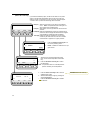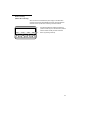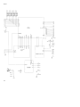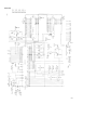
1
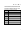
QA-PT User and Service Manual QA-PT Parameter Tester P/N 14625 V.1.29 Copyright © 2001 by METRON. All rights reserved. METRON: USA_ 1345 Monroe NW, Suite 255A Grand Rapids, MI 49505 Phone: (+1) 888 863-8766 Fax: (+1) 616 454-3350 E-mail: [email protected] FRANCE ________________ 30, rue Paul Claudel 91000 Evry, France Phone: (+33) 1 6078 8899 Fax: (+33) 1 6078 6839 E-mail: [email protected] NORWAY________________ Travbaneveien 1 N-7044 Trondheim, Norway Phone: (+47) 7382 8500 Fax: (+47) 7391 7009 E-mail: [email protected] Disclaimer METRON provides this publication as is without warranty of any kind, either express or implied, including but not limited to the implied warranties of merchantability or fitness for any particular purpose. Further, METRON reserves the right to revise this publication and to make changes from time to time to the content hereof, without obligation to METRON or its local representatives to notify any person of such revision or changes. Some jurisdictions do not allow disclaimers of expressed or implied warranties in certain transactions; therefore, this statement may not apply to you. Limited Warranty METRON warrants that the QA-PT Parameter Tester will substantially conform to published specifications and to the documentation, provided that it is used for the purpose for which it was designed. METRON will, for a period of twelve (12) months from date of purchase, replace or repair any defective tester, if the fault is due to a manufacturing defect. In no event will METRON or its local representatives be liable for direct, indirect, special, incidental, or consequential damages arising out of the use of or inability to use the QA-PT Parameter Tester, even if advised of the possibility of such damages. METRON or its local representatives are not responsible for any costs, loss of profits, loss of data, or claims by third parties due to use of, or inability to use the QA-PT Parameter Tester. Neither METRON nor its local representatives will accept, nor be bound by any other form of guarantee concerning the QA-PT Parameter Tester other than this guarantee. Some jurisdictions do not allow disclaimers of expressed or implied warranties in certain transactions; therefore, this statement may not apply to you. Trademarks Duracell is a registered trademark of Duracell, Inc. ii Table of Contents 1. INTRODUCTION............................................................................................................1-1 1.1 Features .......................................................................................................................................1-1 1.2 Specifications ...............................................................................................................................1-1 1.3 General Information......................................................................................................................1-2 2. INSTALLATION.............................................................................................................2-1 2.1 Receipt, Inspection and Return ..................................................................................................2-1 3. OPERATING QA-PT......................................................................................................3-1 3.1 Controls and Terminals ................................................................................................................3-1 3.2 Power ...........................................................................................................................................3-1 3.3 Operating QA-PT..........................................................................................................................3-2 3.4 Cleaning the QA-PT .....................................................................................................................3-2 4. RUNNING TESTS..........................................................................................................4-1 4.1 Pressure / Temperature................................................................................................................4-1 4.2 Gas Flow / Temperature (Models 2G and 2H Only) ....................................................................4-2 4.3 Barometric Pressure and Relative Humidity (Models 2G and 2H Only)........................................................................................................................4-3 5. SERVICING QA-PT .......................................................................................................5-1 5.1 Troubleshooting Procedures .......................................................................................................5-1 5.2 Firmware upload...........................................................................................................................5-1 6. CALIBRATING QA-PT ..................................................................................................6-1 6.1 General.........................................................................................................................................6-1 6.2 Procedures ...................................................................................................................................6-1 7. COMPONENT FUNCTIONS AND PARTS....................................................................7-1 iii 7.1 System Overview..........................................................................................................................7-1 7.2 QA-PT Hardware ..........................................................................................................................7-1 APPENDIX A - SCHEMATIC DIAGRAMS............................................................................. A-1 APPENDIX B – ERROR REPORT FORM ............................................................................. B-1 APPENDIX C - IMPROVEMENT SUGGESTION FORM ....................................................... C-1 iv Manual Revision Record This record page is for recording revisions to your QA-PT User and Service Manual that have been published by METRON AS or its authorized representatives. We recommend that only the management or facility representative authorized to process changes and revisions to publications: • make the pen changes or insert the revised pages; • ensure that obsolete pages are withdrawn and either disposed of immediately, or marked as superseded and placed in a superseded document file, and; • enter the information below reflecting that the revisions have been entered. Rev No Date Entered Reason 0 2000-02-20 Initial Release 1.29-1 2001-01-24 Signature of Person Entering Change METRON General Update v This page intentionally left blank. vi 1. Introduction This chapter describes the METRON QA-PT Parameter Tester’s features and specifications. 1.1 Features QA-PT is a compact, lightweight high performance parameter tester designed to be used by trained service technicians for calibration or test of medical and industrial devices. It is a versatile test instrument, able to measure multiple parameters. Basic parameters cover pressure, vacuum and temperature measurements (Models 1H and 1G). Gas flow, barometric pressure and humidity measurements are included in the enhanced QA-PT (Models 2H and 2G). QA-PT is menu driven, and simple to operate. All functions are set from a 128 x 32 pixel graphical display. 1.2 Specifications Pressure Measurement QA-PT Model 1H or 2H: Operating range: -350 to +350 mmHg Accuracy: 0.1% of range Resolution: 0.1 mmHg Units of measure: mmHg, mBar, cmH2O, PSI, InHg, InH2O, kgcm2 and kPa QA-PT Model 1G or 2G: Operating range: Accuracy: Resolution: Units of measure: -700 to +5000 mmHg 0.05% of range 1 mmHg mmHg, mBar, cmH2O, PSI, InHg, InH2O, kgcm2 and kPa Temperature Measurement Operating range: -200 to +750 °C Accuracy: 1% of reading Resolution: 0.1 °C and °F Units of measure: °C and °F Use standard external temperature probe type PT-100 or PT-1000 (DIN/IEC 751 Class A) for temperature measurements in °C or °F. Temperature Probe Specification: PT-100: Operating range: -200 to +750 °C Accuracy: 100 °C 0.13 °C @ 0.1 °C @ 0 °C 0.2 °C @ 100 °C PT-1000: Operating range: -200 to +750 °C Accuracy: 0.3 °C Barometric pressure QA-PT Model 2G or 2H: It is possible to compensate for the sea level and calibrate for offsets. Operating range: Accuracy: Resolution: Units of measure: 380 to 900 mmHg 2 % of reading 1 mmHg mmHg, mBar, inHg and hPa Temperature Simulation (Optional) High precision tester module for temperature calibration/verification is optional. Operating range: Accuracy: Standard: 25, 37, 38, 40 and 44°C 0.025% of reading YSI 400 Gas Flow QA-PT Model 2G or 2H: Measures with an embedded sensor with 11 calibration points to compensate nonlinearity. Calibration constants stored in firmware. Operating range: Accuracy: Resolution: Compatibility: Units of measure: -750 to +750 ml/min 1% of range or 5% of reading 0.1 ml/min Gas: Air, N2, O2, CO2, H2 and He ml/min (or SCCM - Standard Cubic Centimeters per Minute) Relative Humidity QA-PT Model 2G or 2H: An integrated sensor in the instrument determines relative humidity measurements. 1.3 1-2 Operating range: Accuracy: Resolution: Gas compatibility: Units of measure: 0 to 100% RH 2% @ 25 °C 1% RH Air % RH Temperature Requirements: +15°C to +35°C when operating 0°C to +50°C in storage Display/Control: LCD graphic display, 128 x 32 pixel Data Input/Outputs (1): Bi-directional RS-232C for Computer control Power: 9 Volt Alkaline Battery RG9 or Battery eliminator Case: ABS plastic case Weight: 0.4 kg / 0.9 lbs. with battery General Information Dimensions: D x W x H: 34mm x 94mm x 156mm 1.3 in x 3.7 in x 6.1 in Part No: QA-PT Parameter Tester Standard Accessories: Optional Accessories: 14600: 14601: 14602: 14603: QA-PT QA-PT QA-PT QA-PT 14625: 14620: 14621: 17021: User-/Service Manual QA-PT High-Impact Plastic Carrying Case Tubing Kit 230 VAC to 9 VDC Battery Eliminator -or115 VAC to 9 VDC Battery Eliminator Option - Temperature Simulation PT-100 Temperature Probe PT-1000 Temperature Probe Expansion Chamber Inflation Bulb 17027: 14605: 14611: 14612: 14610: 14622: Model 1H Model 1G Model 2H Model 2G 1-3 This page intentionally left blank. 1-4 2. Installation This chapter explains unpacking, receipt inspection and claims, and the general procedures for QA-PT setup. 2.1 Receipt, Inspection and Return 1. Inspect the outer box for damage. 2. Carefully unpack all items from the box and check to see that you have the following items: 3. 4. • QA-PT Parameter Tester (P.N. dependent on model) • QA-PT User-/Service Manual (P.N. 14625) • Tubing Kit (P.N. 14621) If you note physical damage, or if the unit fails to function according to specification, inform the supplier immediately. When METRON or the company’s Sales Agent, is informed, measures will be taken to either repair the unit or dispatch a replacement. The customer will not have to wait for a claim to be investigated by the Sales Agent. The customer should place a new purchase order to ensure delivery. When returning an instrument to METRON, or the Sales Agent, fill out the address label, describe what is wrong with the instrument, and provide the model and serial numbers. If possible, use the original packaging material for return shipping. Otherwise, repack the unit using: • a reinforced cardboard box, strong enough to carry the weight of the unit. • at least 5 cm of shock-absorbing material around the unit. • nonabrasive dust-free material for the other parts. Repack the unit in a manner to ensure that it cannot shift in the box during shipment. METRON’s product warranty is on page ii of this manual. The warranty does not cover freight charges. C.O.D. will not be accepted without authorization from METRON or its Sales Agent. 2-1 3. Operating QA-PT This chapter describes the controls and terminals of the QA-PT Parameter Tester. It also provides basic operating instructions. 3.1 Controls and Terminals QA-PT Front Panel 1. LCD Display 1.8 cm x 5.8 cm (.7 in. x 2.3 in.) 128 x 32 pixel window displaying messages, test results and function menus. 2. Function Keys Used to select various preset test parameter options, and run the tests. 3. Menu Scroll Keys Used to navigate between and confirm the various preset test parameter options. 4. Test Keys Pressing these opens the relevant test screen: press / temp Pressure / Temperature Test. With QA-PT Models 2G and 2H the following additional tests can be performed: flow / temp Gas Flow / Temperature Test. environment Barometric Pressure / Relative Humidity Test. 5. On / Off Turns the unit on and off. QA-PT Bottom Panel 6. Battery Compartment Compartment for holding a 9 V alkaline battery. QA-PT Left Side Panel 7. Temp. 8-pin mini-DIN plug connector for the temperature cable. Use standard external temperature probe type PT-100 or PT-1000 (DIN/IEC 751 Class A) for temperature measurements in °C or °F. 8. RS-232 8-pin mini-DIN plug for connecting an RS-232. This is used for uploading new firmware, transfer of measuring results, and calibration. You need a customized cable to do this interface. 2.1 mm micro jack for connecting either a 9 VDC or 9VAC plug-in power supply transformer for use in operating the unit from any standard electrical outlet. The jack polarity is center negative. We recommend you use one of METRON’s Battery Eliminators (P.N. 17021 or P.N. 17027), available separately from your METRON Sales Agent. 9. Battery Elim. QA-PT Top Panel 10. Pressure 3.2 Pressure port connector. Power 1. The parameter tester uses 9 V alkaline batteries. It is designed to use as much of the battery as possible. When it detects less than about 6.8 V, it , sounds a continuous tone alarm. When it detects less than 6.0 V, it goes into a shutdown mode 3-1 NOTE Remove the batteries and disconnect the Battery Eliminator if you do not intend to use the QA-PT for an extended period of time. 3.3 The battery is situated in the base of the instrument. Use 9-volt alkaline batteries (Duracell® MN1604 or equivalent). Do not use mercury, air or carbon-zinc batteries. 2. As an alternative to batteries you can power the tester with a 2.1 mm size plug adapter (for example, METRON’s 9 VAC Adapter / Battery Eliminator, P.N. 17021, or 9 VDC Adapter / Battery Eliminator, P.N. 17027). The adapter voltage must not exceed 14.5 volts. Operating QA-PT Operating QA-PT is simple. Make whatever required connections that are needed for the desired test. By using the tester’s keypad you control the tests. 1. Press the tester ON. The LCD window displays the QA-PT model, installed firmware version and the unit’s serial number for about two seconds. The window then displays the pressure / temperature display. This is the default test. NOTE When there is a temperature sensor attached to the unit this will be indicated in the display, If not, “NA” will be displayed. 3.4 2. Select the F1-F4 function keys to set the test parameter presets. Use the right menu scroll key to navigate between the various options. Press the F1-F4 function key under the desired test preset. Press the left menu scroll key to confirm to desired preset. 3. For QA-PT Models 2G and 2H, press a test key to go to a test screen other than the default pressure / temperature test. After reaching the desired test, select the F1-F4 function keys to set the test parameter presets. Use the right menu scroll key to navigate between the various options. Press the F1-F4 function key under the desired test preset. Press the left menu scroll key to confirm to desired preset. Cleaning the QA-PT The outside of the instrument may be cleaned using a damp cloth with mild detergent. Please note that some solvents like Methanol may damage the overlay and cabinet. 3-2 4. Running Tests This chapter describes QA-PT test procedures by function. If you are unfamiliar with the testers’ basic operation, refer to paragraph 3.3, Operating OA-PT. 4.1 Pressure / Temperature 0.0 mmHg . Peak Leak F1 xx °C Zero Unit F3 F2 F4 0.0 mmHg << mmHg F1 0.0 mmHg F2 0.0 mmHg F1 F2 >> mBar mHo F3 F2 45s 60s F3 F4 xx °C << Peaktest Reset F3 1. xx °C xx °C << Leaktest 15s 30s F1 inHo Peak (F1) Peak test will be displayed as long as the measurement is performed. QA-PT will display the highest value of the measurement. The measurement can be reset with the F4 key. Leak (F2) By selecting F1 ->F4 you can set the time for the leak measurement. This interval can be set to 15,30.45 and 60 seconds, and the difference between the start/stop pressure is displayed. Unit (F3) QA-PT can display the result in the following units: mmHg, inHO, mBar, cmHo, kPa, inHg, PSI, Kgcm and C/F. You can convert between them using the menu scroll function. Zero(F4) Resets the pressure measurement. This function should only be used to set zero and not for relative measurements in proportion to a given pressure. F4 2. 3. Press the right menu scroll key ► to view the available units of measurement. Select the desired unit by pressing the appropriate F1-F4 key. Press the left menu scroll key ◄ to confirm the selection. 4. 5. To start the test, pressurize the circuit. 6. Press the left menu scroll key ◄ to return to th preceding screen. 7. Press the left menu scroll key ◄ to return to the preceding screen. 8. Reset = Resets the measurement in progress to zero. Formatted: Bullets and Numbering Select the desired time for the measurement by pressing the appropriate F1-F4 key. The result then appears after this time expires. F4 4-1 Formatted: Bullets and Numbering 4.2 Gas Flow / Temperature (Models 2G and 2H Only) If you select the flow/temp option, the QA-PT will switch on the power supply for the gas flow sensor(battery save function will not turn the power on for this circuit before it's in use) The sensor will need approx. 1 minute to warm up before the measuring result is accurate. Gas (F1) xxx sccm Gas F1 Unit F2 xxx °C Peak Zero F3 F4 Sets the type of gas you are using for the measurement. Note: This parameter must be set right in order to make correct measurements. Unit (F2) Sets SCCM, ml/min for gas flow and °C/F for the temperature. Peak (F3) Peak test is displayed as long as the measurement is performed. QA-PT displays the measurement’s highest value. Reset the measurement with the F4 key. Zero (F4) Resets the pressure measurement. This function should only be used to set zero, and not for relative measurements in proportion to a given pressure. xxx sccm << xxx °C Peaktest Reset F1 xxx sccm F3 F2 >> ml/Min F1 F2 C/F F3 F4 << >> Air N2 O2 CO F1 F2 F3 F4 4-2 Reset = Resets the measurement in pro gress to zero. Select the unit of gas flow with the F1 or F2 keys, and the unit of temperature with the F4 key.. 8. Press the left menu scroll key ◄ to confirm the selection(s). Note: An optional PT100 or PT 1000 temperature probe is necessary for the temperature 6. xxx °C 2. 7. 5. xxx sccm Press the left menu scroll key ◄ to return to the preceding screen. F4 xxx °C << sccm 1. 7. Press the menu scroll keys◄ ► to view the available types of gas. Select the desired type of gas by pressing the appropriate F1-F4 key. Press the left menu scroll key ◄ to validate the selection Formatted: Bullets and Numbering 4.3 Barometric Pressure and Relative Humidity (Models 2G and 2H Only) When environment is selected the power supply for the barometric pressure sensor will be switched ON. The sensor will need about ten seconds to warm up before the measuring results are reliable. xxx hPa xxx %RH HPa mmHg mBar F1 F2 F3 inHg 1. Use the F1 to F4 keys to select the barometric pressure measuring unit. The barometric pressure and the relative humidity are then measured. 2. Return by pressing a test key. F4 4-3 This page intentionally left blank. 4-4 5. Servicing QA-PT This chapter covers QA-PT maintenance and troubleshooting procedures. 5.1 Troubleshooting Procedures 1. Missing Firmware If the firmware is missing from the flash memory the QA-PT will not respond to the ON/OFF button. The unit can be turned on, but the display will be blank. 2. 3. Voltage Levels Signal Min[V] Nominal[V] Max[V] VCC 4.80 5.00 5.20 V5P 4.90 5.00 5.10 V8P 8.20 8.30 8.40 Current consumption Current consumption depends on which QA-PT mode you are running. The power supply for each section is switched on/off according to the selected function. All the values in the following table is calculated from a 9V power supply. 5.2 Function Min[mA] Nominal[mA] Pressure 8 10 Max[mA] 12 Flow 20 22 24 Environment 13 15 17 Firmware upload The first time you upload firmware to the QA-PT you will need to mount a strap on S2. The unit is then turned on, and reset is selected. The firmware upload program is operated from DOS, and will work only on a PC-compatible computer with Windows95/98 (not compatible with Windows NT). Power up the while pressing the F1 button. This will erase the new firmware. Connect an RS-232 cable between the QA-PT and the computer’s COM1 port, and run the d.bat file. The computer will then display instructions on the screen during the upload process. 5-1 This page intentionally left blank. 5-2 6. Calibrating QA-PT 6.1 General The first time that you boot the QA-PT there are no default values for the different sensors (apart from the relative humidity and barometric pressure). This means that none of them will give any measuring results. If the specific sensor is not mounted, the QA-PT displays “NA”. To change the calibration constants you need to access the hidden calibration menu. This is done by selecting press/temp, select unit and then press the right menu scroll key twice. Then, select F4. 6.2 Procedures 1. Pressure Important! A stable temperature is required to do pressure measurements. Pressure is calibrated on five different values so as to compensate for any linearity problem in the pressure sensor. The offset for temperature is calibrated on two values. These values should be approximately 5°C and 20°C (room temperature and refrigerator temperature). All measurements should be performed without disassembling the unit. 2. Linearity calibration Turn the unit on and wait for 15 minutes so as to stabilize the temperature. Select unit in the press/temp menu and press right menu scroll key twice. Then, press F4 to access the hidden calibration menu. Select F1 for pressure calibration. There are two different calibrations, depending upon the pressure sensor. 3. For the measuring range – 350mmHg -> 350mmHg METRON calibrates on the following values: -300, -100, 0, 100 and 300mmHg. For the measuring range –750mmHg -> 5000mmHg we have the following calibration values: -500, -100, 0, 500 and 3000mmHg. Offset Temperature Calibration Immediately after calibrating the linearity you must calibrate the offset temperature. This is done by pressing the right menu scroll key while you’re in the pressure calibration menu. Select HiT (High Temperature, F2). Then, press F4 to calibrate room temperature. LowT (Low Temperature, F1) is calibrated by placing the unit inside of a refrigerator. When the unit has reached a stable temperature, press F4 to calibrate. 6-1 The pressure is now calibrated. Make sure that the unit displays 0 mmHg with different temperatures. 4. Temperature QA-PT is calibrated on 0°C and 100°C for both the PT-100 and the PT-1000 sensors. Access the calibration menu and select F2 for temperature calibration. Connect the calibration resistors and calibrate on 0°C and 100°C. Calibration resistor specifications are listed in the following table. Sensor 0°C 100°C PT-100 100 Ohm 138.5 Ohm PT-1000 1000 Ohm 1385 Ohm These values are used on both sensors, with the alpha value being 0.00385. If another sensor is used, this resistor values would change. 5. Relative Humidity Offset calibration is done by selecting the right menu scroll key and pressing F1 (Humi) in the calibration menu, and adjusting the displayed value in accordance with the relative humidity. F3 will set the step size for F1 and F2. When the right value is set, select F4 to calibrate. If the RH% is not calibrated you should use the standard values. 6. Barometric pressure Offset calibration is done by selecting the right menu scroll key and F3 (Baro) in the calibration menu, and adjusting the displayed value in accordance with the barometric pressure. F3 will set the step size for F1 and F2. When the right value is set, select F4 to calibrate. If the Barometric pressure is not calibrated you should use the standard values. NOTE All flow values must be calibrated because QA-PT will calculate a curve from these results. Verify some of the values in between the calibration values to ensure that values are correct. 6-2 7. Gas Flow Gas flow is calibrated on eleven different flow values ( -1000, 500, -250, -100, -50, 0, 50, 100, 250, 500, and 1000). To calibrate, access the calibration menu and select F4 (flow). Select the flow value with F1, F2 and calibrate with F4. 7. Component Functions and Parts This chapter provides a description of the functions of the main components of the QA-PT, as well as a parts list for cross-reference. 7.1 System Overview The QA-PT consists of four main modules: a central processing unit, a communications module, a power supply and an analog module. It has functions for temperature correction of measuring values, linearity correction, leakage test, peak detection, high-pressure alarm, battery watchdog and user-defined measuring units. There are two different versions of the QA-PT, depending upon which Motorola MPX-series pressure transducer, or sensor is mounted in the unit. QA-PT has a 32 x 132-pixel display, and is operated by the soft keys in the top panel. Measured values are shown in the display, as well as sent to an RS232C serial connector. This serial connector allows the QA-PT to interface with a computer, and be operated remotely. Since the QA-PT’s firmware is stored in its flash memory, it can be upgraded from a computer. The latest firmware version can be downloaded from the Metron’s Website. Calibration adjustments are done through software and the calibration constants are saved in an EPROM. 7.2 QA-PT Hardware Refer to Appendix A, which contains nine schematic diagrams. Seven of these diagrams refer to the QA-PT itself, while the remaining two describe the RS-232 cable and PT-100/PT-1000 temperature cable pin outs, and temperature calibration pin outs. 1. Central Processing Unit. (Refer to Specification Drawing QA-PT CPU, page A-3). The QA-PT is built around a Motorola HC11F1 CPU, with a clock frequency of 2 MHz. The addressing range is divided into two, 32-kilobyte blocks. One is used for program, or “flash” memory, and the other is dedicated to SRAM and I/O. QAPT is always started in a special bootstrap mode, with RXD and TXD short-circuited. This short-circuit starts the EEPROM program (bootload). The program will detect if the F1 key is pressed. If F1 is not active, the short circuit switch will be opened, and the startup sequence is finished. If F1 is active, the firmware upload is triggered. 2. Display. QA-PT has a 122 x 32 pixel graphical display. It is connected to both the address and data bus, J5. The refresh clock is actuated through a 555 timer, U23. The negative supply voltage for the contrast is obtained from the RS-232 transceiver, U19. 3. Analog Module. (Refer to Specification Drawings QA-PT Analog, page A-5; QA-PT Temperature and Flow, page A-6, and; QA-PT Pressure and Barometer, page A-7). QA-PT is designed with a reference voltage that is used to supply the Motorola MPX-series pressure transducer. This is to prevent any deviation in the trans- 7-1 ducer that could affect the measurements. The analog part is based on a Burr-Brown 24-bit differential A/D converter with an SPI interface to the CPU, ADS1213U, and U13. The A/D converter has a built in 4:1 analog multiplexer. The attached sensor will measure in cycles, dependent upon the measuring mode. The A/D converter is also used for relative humidity, internal temperature and battery voltage. The 2.5 V reference voltage is generated in the differential instrumentation amplifier, INA125, U12. The reference voltage supplies a Motorola MPX-series pressure sensor (U8) that is connected to U12. For QA-PT Models 1H and 2H the Motorola pressure sensor is the MPX7050 GP, while for Models 1G and 2G the sensor is the MPX2700 GP. Different pressure sensors can be used for the different measuring ranges. An absolute pressure sensor (Motorola MPX2200A, U6) is used to measure the barometric pressure. The supply voltage for this device is only connected when this is required. The signal amplifier is an Analog Devices AD623AR, U9. In QA-PT Models 2G and 2H Only. Relative humidity is measured with the Honeywell sensor HIH-3605-B, U1. This sensor has an integrated amplifier that is connected to the A/D on the CPU. Additionally, gas flow is measured with another Honeywell sensor with an integrated amplifier, the AWM3303V, U17. The power supply is connected only when required. 4. Power supply. (Refer to Specification Drawing QA-PT Power Supplies, page A-8). The QA-PT uses a 9V battery, or a 7-10V net adapter. The maximum current consumption is less than 30 mA (9V). VCC is generated with a step down switch mode converter, MAX639CSA, U24. The unit is switched ON by setting the shut down signal on U24 HIGH. The unit is switched OFF by setting the signal LOW (this is controlled by the firmware). The analog supply voltages are generated by using a capacitive spennings dobler, LM2660MM, U11 on the VCC signal. Analog 5VDC (V5P) is generated with a 5.0VDC low dropout linear regulator, LP2982AIM5, U2. The analog 8.3VDC (V8P) is generated with a 3.3VDC low dropout linear regulator, LP2982AIM33, U10 with reference to V5P. 7-2 Appendix A - Schematic Diagrams QA-PT ................................................................................................................................................... A-2 QA-PT CPU............................................................................................................................................ A-3 QA-PT Communication........................................................................................................................... A-4 QA-PT Analog ........................................................................................................................................ A-5 QA-PT Temperature and Flow ............................................................................................................... A-6 QA-PT Pressure and Barometer ............................................................................................................ A-7 QA-PT Power Supplies........................................................................................................................... A-8 QA-PT Cables ........................................................................................................................................ A-9 QA-PT Temperature Calibration........................................................................................................... A-10 A-1 QA-PT A-2 QA-PT CPU A-3 QA-PT Communication A-4 QA-PT Analog A-5 QA-PT Temperature and Flow A-6 QA-PT Pressure and Barometer A-7 QA-PT Power Supplies A-8 QA-PT Cables Note: Cable: 3-conductorsx+shield. Shield should be connected to chassis on D-Sub. A-9 QA-PT Temperature Simulation A-10 USA 1345 Monroe NW, Suite 255A Grand Rapids, MI 49505 Phone: (+1) 888 863-8766 Fax: (+1) 616 454-3350 E-mail: [email protected] FRANCE 30, rue Paul Claudel 91000 Evry, France Phone: (+33) 1 6078 8899 Fax: (+33) 1 6078 6839 E-mail: [email protected] From: (name) Address: NORWAY Travbaneveien 1 N-7044 Trondheim, Norway Phone: (+47) 7382 8500 Fax: (+47) 7391 7009 E-mail: [email protected] Phone: Fax: E-mail: Date: Error Report Product: Version: Serial no.: Description of the situation prior to the error: Description of the error: (METRON AS internally) Comments: Received date: Correction date: Ref No. Critical Normal Minor B-1 USA 1345 Monroe NW, Suite 255A Grand Rapids, MI 49505 Phone: (+1) 888 863-8766 Fax: (+1) 616 454-3350 E-mail: [email protected] FRANCE 30, rue Paul Claudel 91000 Evry, France Phone: (+33) 1 6078 8899 Fax: (+33) 1 6078 6839 E-mail: [email protected] From: (name) Address: NORWAY Travbaneveien 1 N-7044 Trondheim, Norway Phone: (+47) 7382 8500 Fax: (+47) 7391 7009 E-mail: [email protected] Phone: Fax: E-mail: Date: Improvement Suggestion Product: Version: Description of the suggested improvement: (METRON AS internally) Comments: Received date: C-1 Correction date: Ref No. Critical Normal Minor USA 1345 Monroe NW, Suite 255A Grand Rapids, MI 49505 Phone: (+1) 888 863-8766 Fax: (+1) 616 454-3350 E-mail: [email protected] FRANCE 30, rue Paul Claudel 91000 Evry, France Phone: (+33) 1 6078 8899 Fax: (+33) 1 6078 6839 E-mail: [email protected] NORWAY Travbaneveien 1 N-7044 Trondheim, Norway Phone: (+47) 7382 8500 Fax: (+47) 7391 7009 E-mail: [email protected]