1
IMPORTANT MANUAL
Do Not Throw Away
Operator's
Manual
Model No.
358.798960
358.798980
Always Wear Eye Protection
CUSTOMER
ASSISTANCE
1-800-235-5878
HOURS (CST)
~[RAFTSMAN
32cc 2-CYCLE ENGINE
Mon. - Sat. 7 a.m.• 7 p.m
Sun.10a.m.·7p.m.
.
®
170 mph Air Velocity
GASOLINE BLOWERNAC
Ii..
as
WARNING
Read the operator's manual
and follow all warnings and
safety instructions. Failure
to do so can result in serious injury.
•
•
•
•
•
Assembly
Operation
Customer Responsibilities
Service and Adjustments
Repair Parts
Sears, Roebuck and Co., Hoffman Estates, IL 60179 U.S.A.
530-084009 (8/11/95)
SAFETY RULES
A
CAUTION
Always disconnect spark plug wire and place wire where it cannot contact spark plug to prevent accidental starting when setting up, transporting, adjusting or making repairs.
OPERATOR SAFETY
• Always wear eye protection to prevent rocks or debris from
being blown or ricocheting into eyes and face which can result
in blindness and/or other serious injury.
• Always wear a respirator or facemask when working with the
unit in dusty environments.
• Always wear heavy, long pants, boots, and gloves. (To avoid
shock of static electricity, do not wear rubber gloves.) Do not
go barefoot or wear short pants, sandals, jewelry, loose clothing, or clothing with loosely hanging straps, ties, tassels, etc.;
they can be caught in moving parts. Secure hair so it is above
shoulder length.
• Do not operate this unit when you are tired, ill, or under the
influence of alcohol, drugs, or medication.
• Keep others including children, animals, bystanders and
helpers at least 30 feet (10 meters) away. Stop the engine
immediately if you are approached.
• Inspect the area before starting the unit. Remove all debris
and hard objects such as rocks, glass, wire, etc. that can ricochet, be thrown, or otherwise cause injury or damage during
operation.
UNITIMAINTENANCE SAFETY
• Disconnect spark plug before performing maintenance except
for carburetor adjustment.
• Use only genuine replacement parts as recommended by
SEARS to avoid creating a hazard and/or voiding your warranty.
• Check air intake openings, blower tubes, elbow tube, and vacuum tubes frequently, always with the engine stopped. Keep
vents and tubes free of debris which can accumulate and
restrict proper air flow.
• Use only quality SEARS accessories and replacement parts
as recommended for this unit.
• Have all maintenance and service not explained in this manual performed by your SEARS Service Center.
FUEL SAFETY
•
•
•
•
Mix and pour fuel outdoors.
Keep away from sparks or flames.
Use a container approved for fuel.
Do not smoke or allow smoking near fuel or the unit or while
using the unit.
• Wipe up all fuel spills before starting engine.
• Move at least 10 feet (3 meters) away from fueling site before
starting engine.
• Stop engine and allow unit to cool before removing fuel cap.
OPERATION SAFETY
• Stop the engine before opening the vacuum inlet door or
attempting to insert or remove the vacuum tubes. The engine
must be stopped and the impeller blades no longer turning to
avoid serious injury from the rotating blades.
• Inspect the entire unit before each use for worn, loose, missing, or damaged parts. Do not use until the unit is in proper
working order.
• Keep the outside surfaces free of oil and fuel.
• Never start or run unit inside a closed room or building.
Breathing exhaust fumes can kill.
• Never use for spreading chemicals, fertilizers, or any other
material which may contain toxic substances.
• Do not set the unit on any surface except a clean, hard area
to start the engine or while the engine is running. Debris such
as gravel, sand, dust, grass, etc. could be picked up by the air
intake and thrown out through the discharge opening, damaging the unit, property, or causing serious injury to
bystanders or the operator.
• Avoid dangerous environments. Do not use in unventilated
areas or where explosive vapors or carbon monoxide build up
could be present.
• Avoid situations which could set the vacuum bag on fire. Do
not vacuum discarded cigars or cigarettes or ash from fireplaces, barbecue pits, brush piles, etc.To avoid spreading fire,
do not use blower near leaf or brush fires, fireplaces, barbecue
pits, ashtrays, etc.
• Do not overreach or use from unstable surfaces such as ladders, trees, steep slopes, rooftops, etc. Use extra care when
cleaning on stairways. Keep firm footing and balance at all
times.
• Never place objects inside the blower tubes; always direct the
blowing debris away from people, animals, glass, and solid
objects such as trees, automobiles, walls, etc. The force of air
can cause rocks, dirt, or sticks to be thrown or to ricochet
which can hurt people or animals, break glass, or cause other
damage. Do not allow the unit to be used as a toy.
• Never place any object in the air intake opening as this could
restrict proper air flow and cause damage to the unit.
• Never run unit without the proper equipment attached. When
used as a blower, always install a blower tube. When used as
a vacuum, always install vacuum tubes and vacuum bag
assembly.
• Use only for jobs explained in this manual.
TRANSPORTING AND STORAGE
• Stop the unit before transporting.
• Allow the engine to cool, and secure the unit before storing or
transporting in a vehicle.
• Empty the fuel tank before storing or transporting the unit. Use
up any fuel left in the carburetor by starting the engine and letting the engine run until it stops.
• Store unit and fuel in an area where fuel vapors cannot reach
sparks or open flames from water heaters, electric motors or
switches, furnaces, etc.
• Store the unit out of the reach of children.
SAFETY NOTICE
Exposure to vibrations through prolonged use of ~asoline powered hand units could cause blood vessel or nerve damage in the
fingers, hands, and joints of people prone to circu ation disorders or abnormal swellings. Prolonged use in cold weather has been
linked to blood vessel damage in otherwise healthy people. If symptoms occur such as numbness, pain, loss of strength, change in
skin color or texture, or loss of feelings in the fingers, hands or joints, discontinue the use of this unit and seek medical attention. An
anti-vibration system does not ~uarantee the avoidance of these problems. Users who operate power tools on a continual and regular basis must monitor closely t eir physical condition and the condition of this unit.
A
LOOK FOR THIS SYMBOL TO POINT OUT IMPORTANT SAFETY PRECAUTIONS.
IT MEANS - ATTENTION!!! BECOME ALERT!!! YOUR SAFETY IS INVOLVED.
-2-
SAFETY RULES
~
Ii..
WARNING
This power unit can be dangerous! This unit can cause serious injury or blindness to the operator and others.
The warnings and safety instructions in this manual must be followed to provide reasonable safety and efficiency in using this unit. The operator is responsible for following the warnings and instructions in this manual and
on the unit. Read the entire operator's manual before assembling and using this unit! Hestrict the use of the
power unit to persons who read, understand and follow the warnings and instructions in this manual and on
the unit. Never allow children to use this tool.
This unit is designed for blower and vacuum use
only. Never use any other attachments with this
unit except the optional gutter attachment.
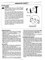
A
WARNING
Blower can throw objects violently. You can be
blinded or injured. Wear eye and leg protection.
~
Face
Shield
Hazard zone for blown objects. Blower can throw
objects violently. Others can be blinded or
injured. Keep people and animals 30 feet
(10 meters) away.
liD
-
Read Operator's Manual. Follow all warnings and
instructions. Failure to do so can result in serious
injury.
.....
_
Operator's
Manual
-3-
___""""...
CONGRATULATIONS
on your purchase of a Sears
Craftsman Gasoline Blower. It has been designed, engineered and manufactured to give you the best possible
dependability and performance.
Should you experience any problems you cannot easily
remedy, please contact your nearest Sears Service Center/Department or call the 1-800 number listed on the front
of this manual. Sears has competent, well trained technicians and the proper tools to service or repair this unit.
Please read and retain this manual. The instructions will
enable you to assemble and maintain your unit properly.
Always observe the "SAFETY RULES."
MODEL NUMBER:
358.798960
358.798980
DATE CODE/SERIAL
AIR VELOCITY
170mph
AIR VOLUME
350 cu. ft.lmin.
ENGINE
32cc 2-cycle Air-Cooled
ENGINE RPM
Operating
Idle
7000-7600
3800-4600
.
FUEUOIL MIX RATIO
40:1 (3.2 oz. per
gallon gas)
IGNITION
Solid State
(Airgap010" to .014")
IGNITION TIMING
Non-adjustable, fixed
SPARK PLUG
Champion (RCJ-SY)
SPARK PLUG GAP
025"
NO.:
DATE OF PURCHASE:
THE MODEL AND SERIAL
FOUND ON THE PRODUCT.
NUMBER
WILL
BE
YOU SHOULD RECORD BOTH SERIAL NUMBER
AND DATE OF PURCHASE AND KEEP IN A SAFE
PLACE FOR FUTURE REFERENCE.
MAINTENANCE
PRODUCT SPECIFICATIONS
AGREEMENT
A Sears Maintenance Agreement is available on this
product. Contact your nearest Sears Store for details.
CUSTOMER RESPONSIBILITIES
• Read and observe the safety rules.
• Follow a regular schedule in maintaining, caring for, and
using your unit.
• Follow the instructions under "Customer Responsibilities" and "Storage" sections of this Operator's Manual.
SPECIAL NOTICE
For users on U.S. Forest Land and in some states, including
California (Public Resources Codes 4442 and 4443), Idaho,
Maine, Minnesota, New Jersey, Oregon, and Washington:
Certain internal combustion engines operated on forest,
brush, and/or grass-covered lands in the above areas are
required to be equipped with a spark arrestor, maintained in
effective working order, or the engine must be constructed,
equipped, and maintained for the prevention of fire. Check
with your state or local authorities for regulations pertaining to
these requirements. Failure to follow these requirements is a
violation of the law. This unit is not factory-equipped with a
spark arrestor; however, a spark arrestor is available as an
optional part. If a spark arrestor is required in your area, contact your SEARS Service Center/Department for the correct
kit.
Manufactured under one or more of the following U.S. patents: 5.269.665; 5.211,144;
5.174.255; 5.035.586: 4.940.028: 4.846.123; 4,674,146; 4,474,327; 4.413.371; 4,404,706;
4,402.106; 4.387.852; 4.325,163; 4.286.675; Re.33.050; 0349,983; 0322.971; 0304.510:
0299.074; 0266,355; 0263.547. Other U.S.and foreign patents pending.
FULL TWO YEAR WARRANTY ON SEARS BEST CRAFTSMAN
GAS BLOWER
For two (2) years from date of purchase, when this Gas Blower is maintained, lubricated, and tuned up according to the
instructions in the owner's manual, Sears will repair, free of charge, any defects in material or workmanship.
This warranty excludes blower tubes, spark plug and air cleaner, which are expendable parts and become worn during
normal use.
If this Blower is used for commercial purposes, this warranty applies for 90 days from date of purchase. If this Blower is
used for rental purposes this warranty applies for 30 days from date of purchase. This warranty applies only while this
product is in use in the United States.
WARRANTY SERVICE IS AVAILABLE BY RETURNING THE BLOWER TO THE NEAREST SEARS SERVICE CENTER
IN THE UNITED STATES.
This warranty gives you specific legal rights, and you may also have other rights which vary from state to state,
SEARS, ROEBUCK AND CO., D/817WA, HOFFMAN ESTATES, IL 60179
-4-
TABLE OF CONTENTS
Safety Rules
2
Product Specifications
.4
warranty
Accessories
Assembly
Operation
4
5
6
9
Customer Responsibilities
Service and Adjustments
Storage
Trouble Shooting Points
Repair Parts
Repair Parts Ordering/Service
15
18
21
22
23
Back Cover
INDEX
A
Accessories
Adjustments
Carburetor
Air Filter
Assembly
5
20
16
6
B
Blower Tube
Carburetor Adjustments
Carton Contents
Customer Responsibilities
Spark Plug
Engine
Fuel/Oil
Spark Plug
Starting
Storage
7
C
20
6
15
4, 16
E
13
4, 16
14
21
F
Fuel Filter
Fueling
How To Use Your BlowerNac
H
Know Your Blower
Maintenance Schedule
Model Number
Operation
K
9
M
15
4
o
9
p
Product Specifications
Repair Parts
Ordering
Service and Adjustments
Starter Rope
Starting
Storage
Trouble Shooting Points
17
13
Vacuum Bag
Vacuum Tube
10
Warranty
.4
R
23
Back Cover
S
18
18
14
21
T
22
V
..18
7
W
4
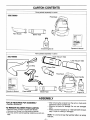
ACCESSORIES
These accessories and attachments were available when the unit was originally purchased. They are also available at most
Sears retail outlets and service centers. Most Sears stores can order these items for you when you provide the model
number of your unit.
Accessories
Safety
Goggles
~
Spark
Plug
A
~
Gutter
Attachment Kit
~""~.
~
Vacuum
Attachment Kit
Q«~
-5-
Gas
Can
t3
Air
Filter
Sears 2-Cycle
Engine Oil
n"
M ~.
CARTON CONTENTS
Parts packed separately in carton
358.798960
Flare Nozzle
o ))0]
Blower Tube
IJ
3.2 oz.
40:1
2-Cycle Engine Oil
_-
_ ..
D
....,................ ,
...
"E+!;£,:
'_r
:;s:~;';'":>
Operator's Manual
Parts packed separately in carton
358.798980
_'
......
D
.,. .....
00 __
....
=~lIXln
.3.2 oz.
rx8.W~¥:~"Cn
40:1
ir.?·':.~;·:;
Operator's Manual
Flare Nozzle
Blower Tube
2-Cycle
Engine Oil
ASSEMBLY
TOOLS REQUIRED FOR ASSEMBLY
• Standard Screwdriver
TO REMOVE BLOWER FROM CARTON
• Remove carton contents included with Blower.
• Remove your Blower from the packing material.
• You may use the opened packing material as a work surface.
• After removing the contents from the carton, check parts
against the Carton Contents list.
• Examine the parts for damage. Do not use damaged
parts.
• Notify Customer Assistance at 1-800-235-5878 immediately if a part is missing or damaged.
NOTE - It is normal to hear the fuel filter rattle in an empty
fuel tank.
-6-
ASSEMBLY
HOW TO ASSEMBLE YOUR BLOWER
r>... WARNING
as
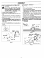
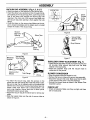
VACUUM TUBE ASSEMBLY
(Fig. 2 & 3)
• Remove the blower tube from the engine.
• Set the unit, blower outlet up, on a flat surface. Open the
vacuum inlet cover as follows:
- Insert a screwdriver into latch area.
- Gently tilt the tip of the screwdriver forward towards the
blower outlet and open the vacuum inlet cover with
your other hand.
• Hold open vacuum inlet cover and align the grooves on
the upper vacuum tube with the locking tabs inside the
vacuum inlet. Insert the upper vacuum tube and turn
clockwise until parts snap together.
• Assemble the vacuum tubes by aligning the slanted end
of the lower vacuum tube with the blower outlet as
shown. Push the two tubes together until they are snug.
NOTE - The bottom end of the lower vacuum tube is cut at
an angle. Make sure slanted end of vacuum tube is aligned
with blower outlet.
Stop the engine before opening the vacuum
inlet door or attempting to insert or remove the
vacuum tubes. The engine must be stopped and
the impeller blades no longer turning to avoid
serious injury from the rotating blades.
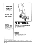
BLOWER TUBE ASSEMBLY (Fig. 1)
• Locate the two locking tabs on the side of the blower
tube.
• Align the grooves on the nozzle with the locking tabs on
the blower tube and push the nozzle onto the blower
tube.
• Turn the nozzle clockwise until the parts snap into place
and are firmly tightened.
• Align grooves on the blower tube with locking tabs in the
blower outlet (inset) and push the blower tube into the
blower outlet.
• Turn the blower tube clockwise until the parts snap into
place and are firmly tightened.
• Turn flare nozzle and blower tube counterclockwise for
removal.
Locking Tabs
Locking Tabs
Blower
Outlet
Grooves
Blower Tube
Flare Nozzle
~~{h
\
~'U~!
Glves
Figure 2
\
\
Locking Tabs
Figure 1
Figure 3
-7-
ASSEMBLY
VACUUM BAG ASSEMBLY (Fig. 4, 5, 6 & 7)
• Open the zipper on the large end of the vacuum bag.
• Insert the elbow tube, grooved end first, through the zipper opening in the vacuum bag. Then, push the grooved
end of the elbow tube through the vacuum bag tube
opening in the other end of the vacuum bag. Make sure
the vacuum bag tube opening is flush against the tube
flange.
• Close the zipper on the vacuum bag. Make sure the zipper is closed completely and the zipper seam is tucked
toward the inside of the vacuum bag,
Elbow
Curved
~tothe
Right
Figure 6
Vacuum Bag/
Shoulder Strap
Seam
Strap Retainer
Figure 4
Figure 7
SHOULDER STRAP ADJUSTMENT
(Fig. 7)
• Place vacuum bag strap around your back and over your
left shoulder. Snap vacuum bag hook onto the strap
retainer in the top handle.
• Adjust the shoulder strap until the vacuum tube is
suspended off the ground.
BLOWER CONVERSION
Figure 5
• To attach the vacuum bag, align the grooves on the
elbow tube with the locking tabs inside the blower outlet.
Be sure to align the dot marked mulch on the elbow tube
with the dot on the blower housing. Insert elbow tube into
blower outlet; twist elbow tube counterclockwise until
parts snap together. Assure bent end of elbow points
downward toward vacuum tube.
• Adjust the vacuum bag at the elbow tube to remove any
twists.
• Slide the looped strap over the end of vacuum tube as
shown in Figure 6.
-8-
• Stop the engine. Allow the engine to cool.
• Remove the vacuum tubes and vacuum bag assembly.
• Secure the vacuum inlet cover. Make sure that the latch
on the vacuum inlet cover is securely fastened.
• Reinstall the blower tubes as shown in the "Blower Tube
Assembly" section.
CHECK LIST
• Check all fasteners. Make sure they are tight and there
are no loose parts.
OPERATION
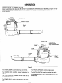
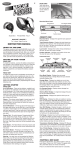
KNOW YOUR BLOWER (Fig. 8)
READ THIS OPERATOR'S MANUAL AND SAFETY RULES BEFORE OPERATING YOUR BLOWER. Compare the illustrations with your unit to familiarize yourself with the location of the various controls and adjustments. Save this manual for
future reference.
----Plug
...
Spark
Primer Bulb
,
Assist Handle
on Some Models
(See Hardware Chart)
j
Flare Nozzle
<,
Blower
Tube
/
Starter
Rope
Handle
...-----
Figure 8
The CHOKE LEVER is used for starting a cold engine.
The THROTILE
The STARTER
engine.
The IGNITION SWITCH is used to stop/start the engine.
ROPE HANDLE
is used for starting the
TRIGGER controls engine speed.
The FLARE NOZZLE is used to disperse the air
a wider area.
The THROTTLE LOCK is used to hold the throttle in the
run and starting position.
The PRIMER BULB is used to circulate fuel to the carburetor.
-9-
flow over
OPERATION
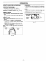
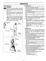
HOW TO USE YOUR BLOWERNAC
PRIMER BULB
• The primer bulb is used to circulate fuel to the carburetor.
• The primer bulb is activated by pressing on it with your
thumb.
STOPPING YOUR ENGINE
• Move ignition switch to the "STOP" position.
• If engine does not stop, turn choke knob to full.
THROTTLE CONTROL GROUP (Fig. 9 & 10)
THROTTLE TRIGGER
• The throttle trigger allows for variable control of engine
speed.
• The throttle trigger is actuated by the index finger on your
right hand.
THROTTLE LOCK
• The throttle lock allows for faster engine speeds during
starting.
• The throttle lock is engaged by the following steps:
- Grasp the top handle and squeeze the throttle trigger
fully and hold.
- Depress the throttle lock with your thumb and hold.
- Release your grip on the throttle trigger while continuing to hold the throttle lock,
NOTE - Verify the throttle trigger stays in the advanced
position.
Figure 9
-10 -
CHOKE
• The choke provides additional fuel when starting a cold
engine.
• The choke is actuated by turning the choke knob.
• The choke has three positions: Off" half and full.
Figure 10
OPERATION SAFETY
Bl,.OWER SAFETY
A
WARNING
The blower causes objects to be thrown violently. The
operator must wear a safety face shield or goggles.
Always wear heavy, long pants and boots. Keep others at
least 30 feet (10 meters) away.
This unit will throw objects. Keep others including children, animals, bystanders and helpers at least 30 feet (10
meters) away from the operator and unit. Stop the engine
if you are approached. In areas where other people and
animals are present, such as near sidewalks, streets,
houses, etc., it is strongly recommended that the operator use the buddy system; that is, have another person
serve as a "look-out," keeping himself and others at least
30 feet (10 meters) away from the operator.
~
Face
Shield
Do not assemble or disassemble the vacuum tube while
the engine is running. Inserting or removing the vacuum
tube while the engine is running can result in serious
injury. Always stop the engine and disconnect the spark
plug before unclogging the unit or performing any maintenance on the vacuum bag.
Use Only Good Quality
Replacement Parts
OPERATOR SAFETY
• Read your Operator's Manual. Make sure you completely
understand and can follow all warnings and safety
Instructions in the manual before operating.
• Always wear a respirator or facemask when working in
dusty environments.
• Always wear eye protection to prevent rocks or debris
from being blown or ricocheting into eyes and face which
can result in blindness or other serious injury.
• Always wear heavy, long pants, boots, and gloves. (To
avoid shock of static electricity, do not wear rubber
gloves.) Do not go barefoot or wear short pants, sandals,
jewelry, loose clothing, or clothing with loosely hanging
straps, ties, tassels, etc. Secure hair so it is above
shoulder length.
UNIT SAFETY
• Inspect the entire unit before each use. Replace damaged parts. Check for fuel leaks and make sure all fasteners are in place and securely fastened.
• Check air intake opening, blower tubes, vacuum tubes,
and elbow tube frequently, always with engine stopped
and spark plug disconnected. Keep vents and discharge
tubes free of debris which can accumulate and restrict
proper air flow.
• Never place objects inside blower tubes; always direct
blowing debris away from people, animals, glass, and
solid objects such as trees, automobiles, walls, etc. The
force of air can cause rocks, dirt, or sticks to be thrown
or to ricochet which may hurt people or animals, break
glass, etc.
• Never run the unit without the proper equipment
attached. When using your unit as a blower always install
blower tubes. When using your unit as a vacuum, always
install vacuum tubes and vacuum bag assembly. Make
sure vacuum bag assembly is completely zipped.
• When using the unit as a vacuum, always use the shoulder strap to avoid loss of control.
• Use only quality SEARS accessories and replacement
parts as recommended for this unit.
BLOWERNACUUM
SAFETY
• As a blower, the unit is designed to sweep debris, grass,
straw, leaves, small twigs, or light snow. It can also be
used for fast drying wet outdoor areas such as a patio,
sidewalk, carport, etc. Never use for spreading or misting
chemicals, fertilizers, or any other materials which may
contain toxic substances.
• As a vacuum, the unit is designed to pick up dry material such as leaves, grass, small twigs, and bits of paper.
Do not attempt to vacuum stones, gravel, metal, broken
glass, or any other debris which may cause damage to
the impeller. Do not attempt to vacuum water or any
other liquids. Vacuuming water or other liquids will cause
damage to the engine. Avoid situations that could catch
the vacuum bag on fire. Do not operate near an open
flame. Do not vacuum discarded cigars or cigarettes or
ash from fireplaces, barbecue pits, brush piles, etc.
• Inspect area before starting engine. Remove all debriS
and objects such as rocks, glass, wire, large sticks, etc.
that can cause damage during operation.
• Use the correct operating position. Do not overreach or
use from unstable surfaces such as ladders, trees, steep
slopes, roof tops, etc. Keep firm footing and balance at
all times.
-11 -
OPERATION
BLOWER TIPS
OPERATING TIPS
~
r>...
• Always work going away from solid objects such as
walls, trees, automobiles, and fences.
• Clean corners by starting in corners and moving outward
to flat areas to prevent an accumulation of debris which
could fly into face.
• Be careful when working near plants. The force of the air
could damage tender plants.
• Direct air flow by directing the nozzle down or to one
side.
• Vary the air flow by adjusting your grip on the throttle trigger.
• While using the model 358.798980 use the assist handle
located on the back of the unit when working above the
waist or when a two-handed grip is desired.
• Uses for your blower:
- Sweeping debris or grass clippings from driveways,
sidewalks, patios, parks, parking lots, barns, stadiums,
etc.
- Blowing grass clippings, straw, or leaves into piles.
- Fast drying wet outdoor areas such as a patio.
- Removing debris from corners, around [oints, and
between bricks.
- Blowing light snow from driveways, sidewalks, or
patios.
WARNING
Do not use the unit as a blower without the
blower tubes properly attached to avoid flying
debris and/or impeller contact which can cause
serious injury,
Always wear eye protection to prevent rocks or
debris from being blown or ricocheting into the
eyes and face which can result in blindness or
serious injury.
Do not use the unit as a vacuum without the
vacuum
tube and vacuum
bag properly
attached to avoid flying debris and/or impeller
contact which can cause serious injury. Always
make sure the vacuum bag is completely
zipped before the engine is started.
Eye
Protection
VACUUM TIPS
Assist Handle
• When using your unit as a vacuum, best results are
achieved when the unit is operated at full throttle.
Engage the throttle lock before beginning vacuuming
procedures.
• Move the unit slowly back and forth over debris to' be
vacuumed. Avoid forcing the vacuum tube into a pile of
debris as this can clog the unit.
• The vacuum can pick up objects that are too big to pass
through the impeller. This type of object will fall out of the
vacuum tubes when the engine is stopped.
• If the unit becomes clogged:
- Stop the engine and disconnect the spark plug wire.
Do not attempt to remove obstructions with the engine
running.
- Wait until the impeller has completely stopped turning,
then remove the vacuum tube.
- Carefully reach into the vacuum opening and clear out
debris.
• The vacuum bag must be properly emptied and maintained to avoid deterioration and obstruction of air flow
which will reduce the performance of the vacuum.
- Empty the vacuum bag after each use.
- Remove the vacuum bag/elbow from the unit by turning it in a clockwise direction. Do not store vacuum bag
containing leaves, grass, etc.
- Wash the vacuum bag once a year as follows:
• Turn the vacuum bag inside out.
• Hang it up,
• Thoroughly hose it down.
• Let vacuum bag hang until dry.
....
Blower
Operation
Figure 11
Assist Handle
Vacuum
Operation
Figure 12
-12 -
OPERATION
40:1 2-CYCLE AIR-COOLED ENGINE OIL
BEFORE STARTING ENGINE
~
Ii..
CRAFTSMAN 40:1 2-cycle engine oil (AIR-COOLED) is
strongly recommended. This oil is specially blended with
fuel stabilizers for increased fuel stability (extends fuel life
up to 5 times longer) and reduced smoke.
WARNING
Be sure to read the fuel safety information in the
safety rules section on page 2 of this manual
before you begin.
If CRAFTSMAN 40:1 2-cycle engine oil (AIR-COOLED) is
not available, use a good quality 2-cycle engine oil (AIRCOOLED) that has a recommended fuel mix ratio of 40:1.
If you do not understand the fuel safety section
do not attempt to fuel your unit; seek help from
someone who does understand the fuel safety
section or call the customer assistance helpline
at 1-800-235-5878.
IMPORTANT! Do not use:
• AUTOMOTIVE OIL
• BOAT OILS (NMMA, BIA, etc.)
GASOLINE
These oils do not have proper additives for 2-cycle engines
(AIR-COOLED) and can cause engine damage.
The two-cycle engine on this product requires a fuel mixture of regular unleaded gasoline and a high quality 40:1
2-cycle engine oil (AIR-COOLED) for lubrication of the
bearings and other moving parts. The correct fuel/oil mixture is 40:1 (see Fuel Mixture Chart). Too little oil or the
incorrect oil type will cause poor performance and may
cause the engine to overheat and seize.
GASOLINE AND OIL MIXTURE
Mix gasoline and oil as follows:
• Consult chart for correct quantities.
• Do not mix gasoline and oil directly in the unit's fuel tank.
Gasoline and oil must be premixed in a clean approved fuel
container. Always use fresh regular unleaded gasoline.
This engine is certified to operate on unleaded gasoline.
IMPORTANT - Experience indicates that alcohol blended
fuels called gasohol (or using ethanol or methanol) can
attract moisture, which leads to oil/gas separation and formation of acids during storage. Acidic gas can damage the
fuel system of an engine while in storage. To avoid engine
problems, the fuel system should be emptied before storage for 30 days or longer. Drain the gas tank, then run the
fuel out of the carburetor and fuel lines by starting the
engine and letting it run until it stops. Use fresh fuel next
season. See STORAGE instructions for additional information. Never use engine or carburetor cleaner products in
the fuel tank or permanent damage may occur.
FUEL STABILIZER
Fuel stabilizer is an acceptable alternative in minimizing
the formation of fuel gum deposits during storage. Add stabilizer to gasoline in fuel tank or storage container. Always
follow the fuel mix ratio found on the stabilizer container.
Run engine at least 5 minutes after adding stabilizer to
allow the stabilizer to reach the carburetor. You do not have
to drain the fuel tank for storage if you are using fuel stabilizer.
FOR ONE GALLON:
• Pour 3.2 ounces of high quality, 40:1 2-cycle engine oil
(AIR-COOLED) into an empty, approved one gallon
gasoline container.
• Add one gallon of regular unleaded gasoline to the galIon container, then securely replace the cap.
• Shake the container.
• The mixture is now ready for use. Fuel stabilizer can be
added at this time if desired; follow mixing instructions on
the label.
FUEL MIXTURE CHART
40:1 Fuel:Oil Mix Ratio
Gasoline
1 gallon
2.5 gallons
NOTE - Fuel containers may hold more than the specified
amount. If too much gasoline is in the container, the resulting gas-to-oil fuel mixture will not be correct for proper
engine operation.
CRAFTSMAN 40:1 2-cycle engine oil (AIR-COOLED) is
specially blended with fuel stabilizers. If you do not use this
Sears oil, you can add a fuel stabilizer (such as CRAFTSMAN No. 33500) to your fuel tank.
-13
Oil (fl. oz.)
3.2
8.0
-
OPERATION
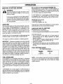
STOPPING YOUR ENGINE
• Move the ignition switch to the "Stop" position.
• If engine does not stop, move the choke lever to the "Full
Choke" position.
A
WARNING
When starting the engine, hold the unit as shown
in Figure 13. Do not set the unit on any surface
except a clean, hard area while the engine is running. Debris such as gravel, sand, dust, grass,
etc. could be picked up by the air intake and
thrown out through the discharge opening, damaging the unit or property or causing serious
injury to bystanders or operator.
Starting could require pulling the starter rope handle many
times depending on how badly the unit is flooded. If engine
still fails to start, refer to the "Trouble Shooting" chart.
Once the engine starts, allow the engine to run 15
seconds, then move the choke lever to "Off Choke". Allow
the engine to run for 30 more seconds at "Off Choke"
before releasing the throttle lock.
NOTE - If the engine dies with choke lever at "Off Choke"
position, move the choke lever to "Half Choke". Pull starter
rope three times. Move choke lever to "Off Choke" position,
pull the rope until engine runs. Run engine 30 seconds with
throttle trigger fully squeezed.
• Release throttle lock by squeezing the trigger.
• To stop the engine, move the ignition switch to the "Stop"
position.
For safe starting and operation, follow all safety
precautions in this operator's manual and labels
on the unit. Dress properly before starting engine.
On mulch bladed units, blades are noisy during
start-up.
Avoid any contact with the muffler. A hot muffler
can cause serious burns.
BASIC STARTING PROCEDURE
(Fig. 13 & 14)
STARTING A WARM ENGINE
COLD ENGINE START AND WARM ENGINE
START AFTER RUNNING OUT OF FUEL
• Fuel engine with 40:1 fuel mix (3.2 oz. to 1 gallon gas).
Move 10 feet (3 meters) away from fueling site.
• Move ignition switch off of the "Stop" position.
• Activate throttle lock.
• Press primer bulb 6 times.
• Actuate choke by moving the choke lever to the "Full
Choke" position.
• Hold the unit in the starting position as shown. When
using the unit as a blower, make sure the blower end is
directed away from people, animals, glass, and solid
objects. When using the unit as a vacuum, make sure the
vacuum end is directed away from people, animals,
glass, and solid objects and that you support the vacuum
tube off the ground during starting.
• Pull starter rope sharply five times.
NOTE - The engine may sound as if it is trying to start
before the 5th pull. If so, go to the next step immediately.
Blower
Starting
Position
• Move the choke lever to the "Half Choke" position.
• Pull the starter rope sharply until the engine runs, but no
more than six pulls.
If the engine still has not started, it is probably flooded.
Flooded engines can be cleared of excess fuel with the
following procedure.
• Move the choke lever to the "Off" position.
• Press primer bulb 6 times.
• Squeeze and hold the throttle trigger.
• Pull starter rope to clear the engine of excess fuel.
•
•
•
•
•
•
•
Move the ignition switch off of the "Stop" position.
Activate throttle lock.
Press primer bulb 6 times.
Move choke lever to the "Off Choke" position.
Squeeze throttle trigger.
Pull starter rope until engine starts.
Release the throttle lock by squeezing the trigger.
Vacuum
Starting
Position
Figure 14
DIFFICULT STARTING OR FLOODED ENGINE
The engine may be flooded with too much fuel if it has not
started after 20 pulls.
NOTE - When pulling the starter rope, do not use the full
extent of the rope. Do not let the starter snap back. Hold
the handle and let the rope rewind slowly.
-14 -
Flooded engines can be cleared of excess fuel with the
following procedure:
• Move ignition switch off of the "Stop" position.
• Activate the throttle lock.
• Move the choke lever to the "Off Choke" position.
• Squeeze and hold the throttle trigger.
• Pull starter rope handle until engine starts.
• Release the throttle lock by squeezing the trigger.
Starting could require pulling starter rope handle many
times depending on how badly unit is flooded. If engine still
fails to start, refer to ''TROUBLE SHOOTING" chart or call
the 1-800 number listed on the front cover of this manual.
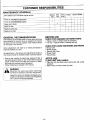
CUSTOMER RESPONSIBILITIES
MAINTENANCE SCHEDULE
Before
Use
Fill in dates as you complete regular service
After
Use
Every
5 Hrs.
Yearly
Service Dates
.;'
Check for damaged or worn parts
.;'
Check for loose fasteners & parts
.;'
Clean unit & labels
.;'
Clean air filter
.;'
Replace spark plug
.;'
Replace fuel filter
BEFORE USE
GENERAL RECOMMENDATIONS
The warranty on this blower does not cover items that have
been subjected to operator abuse or negligence. To receive
full value from the warranty, operator must maintain blower
as instructed in this manual.
CHECK FOR DAMAGED OR WORN PARTS
Some adjustments will need to be made periodically
properly maintain your unit.
•
•
•
•
•
• Tighten, repair or replace parts as necessary.
• Fuel cap - replace broken or leaking fuel cap.
CHECK FOR LOOSE FASTENERS AND PARTS
to
All adjustments in the Service and Adjustments section of
this manual should be checked at least once each season.
• Once a year, replace the spark plug, replace air filter. A
new spark plug and clean or new air filter element assures
proper air-fuel mixture and helps your engine run better,
last longer and reduces harmful emissions.
• Follow maintenance schedule in this manual.
A
Blower Tube
Blower Nozzle
Vacuum Inlet Cover
Blower Outlet
Vacuum Bag
AFTER USE
CLEAN UNIT AND LABELS
• Clean the unit and labels using a damp cloth with a mild
detergent.
• Wipe off the unit with a clean dry cloth.
WARNING
Disconnect the spark plug before performing
maintenance except for carburetor adjustments.
Inspect the entire unit. Replace damaged parts.
Check for fuel leaks and make sure all fasteners
are in place and securely fastened.
-15 -
CUSTOMER RESPONSIBILITIES
EVERY 5 HOURS
YEARLY
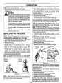
CLEAN AIR FILTER (Fig. 15)
~
1">..
REPLACE SPARK PLUG (Fig. 16)
CAUTION
To avoid creating fire hazard and producing
harmful emissions, do not clean filter in gasoline
or other flammable solvent.
The holes in the air filter must be fitted over the
posts on the air filter cover. When installing the
air filter/cover assembly, be sure that the filter
does not hang on the choke lever screw.
The spark plug should be replaced each year to ensure the
engine starts easier and runs better.
Spark plug gap should be .025",
• Pull off the spark plug boot.
• Remove and discard the spark plug.
• Replace with correct spark plug and tighten with spark
plug wrench (10-12 Ib-ft),
• Cover spark plug with spark plug boot.
A dirty air filter decreases the life and performance of the
engine and increases fuel consumption and harmful emissions.
Always clean after 5 tanks of fuel or 5 hours of operation,
whichever is less, Clean more frequently in dusty conditions.
• Move the choke lever to the "Full" position.
• Remove the air filter cover on top of the unit (under the
handle) by depressing the air filter cover latch.
• Wash the air filter in soap and water.
• Squeeze the air filter dry.
• Add 4 or 5 drops of oil to the air filter. Avoid soaking the
air filter with oil.
• Squeeze the air filter to distribute oil.
• Reassemble the air filter onto the cover.
• Reassemble air filter/cover assembly to unit. Return
choke lever to the "Off" position.
/
---
Air Filter ____
Cover
Air Filter
Figure 15
-16 -
Figure 16
CUSTOMER RESPONSIBILITIES
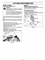
REPLACE FUEL FILTER (Fig. 17 & 18)
The fuel filter should be replaced after each season. Never
operate your unit without a fuel filter. Be careful not to damage fuel line while removing the fuel filter.
• Run fuel tank dry of fuel before proceeding with this step.
• Remove fuel cap and allow it to hang to side of motor.
• Using a small pair of needle nose pliers, grasp fuel cap
retainer, holding it in tank opening and pull out.
• With cap out of tank, use a small section of bent wire
similar to that shown in the illustration to catch fuel line
and slowly pull from tank. When fuel filter appears in
opening, grasp with fingers and remove from tank.
• Once filter is out of tank, hold fuel line close to fuel filter.
Remove fuel filter by twisting and pulling at the same
time.
• Replace fuel filter.
• Reverse process for installation.
~'IFuelcap
Figure 17
Fuel
/Filter
Filter ... ~
~
1 Neck
Figure 18
-17 -
SERVICE AND ADJUSTMENTS
STARTER ROPE (Fig. 19, 20, 21,22, 23, 24 & 25)
~
.Ii..
• Remove the 5 screws from the pulley housing, then
remove the pulley housing and pulley from the engine .
WARNING
Do not remove the pulley when replacing the
starter rope. Always wear eye protection when
servicing the starter rope. The recoil spring,
located beneath the pulley, is under tension. If
the spring pops out, serious injury can result.
Remove
Screws
Replace the starter rope if the rope breaks or is badly
worn.
NOTE - When replacing an unbroken rope, cut the rope
and allow the rope to rewind onto the pulley.
REPAIR OR REPLACE STARTER ROPE
• Disconnect spark plug wire from the spark plug.
• Set unit, blower outlet up, on a flat surface. Open the
vacuum inlet cover as follows:
- Insert a screwdriver into the latch opening. (Inset).
- Gently twist the screwdriver while opening the vacuum
inlet cover with your other hand.
• Remove the impeller nut and washers while holding the
impeller and cutter blades.
Figure 21
• Remove the rope retainer screw from pulley; then,
remove the broken piece of rope, if any.
• Grasp the pulley ratchet and wind the pulley clockwise
until the pulley stops. Then, slowly unwind the pulley
counterclockwise until the pulley notch is aligned with the
pulley housing notch, then unwind pulley one complete
turn. Insert the hex wrench into the hole formed by the
aligned notches.
• Move away from the fuel tank and melt the ends of the
new rope.
• Allow each melted end to drip once; then while the rope
is still hot, pull each melted end through a clean rag to
obtain a smooth, pointed end.
Figure 19
• Remove the 4 impeller shroud screws. Then, remove the
2 engine shroud screws located by the spark plug.
Remove the impeller shroud from the engine shroud.
Impeller
Shroud -
~
~
Screws~'r---Shroud
.
Engine·
Shroud
~
Engine
Q
I~
c::>""--
~~Impeller
~
Figure 20
Screws
O-Ring
Shroud
Figure 22
• Insert one end of the rope through the handle and
secure with a knot. Leave 3/16" pigtail behind the knot.
• Insert the other end of the rope through the metal
grommet, then under the rope guide.
-18-
FOR CALIFORNIA RESIDENTS ONLY WHEN
SEEKING SERVICE IN CALIFORNIA
CALIFORNIA EMISSION CONTROL
WARRANTY STATEMENT
YOUR WARRANTY RIGHTS AND OBLIGATIONS
The California Air Resources Board and Sears, Roebuck and Co., USA, are pleased to explain
the emissions control system warranty on your 1995 lawn and garden equipment engine. In
California, new utility and lawn and garden equipment engines must be designed, built, and
equipped to meet the State's stringent anti-smog standards. Sears must warrant the emission
control system on your lawn and garden equipment engine for the periods of time listed below
provided there has been no abuse, neglect, or improper maintenance of your lawn and garden
equipment engine.
Your emission control system includes parts such as the carburetor and the ignition system.
Where a warrantable condition exists, Sears will repair your lawn and garden equipment engine
at no cost to you. Expenses covered under warranty include diagnosis, parts, and labor.
MANUFACTURER'S WARRANTY COVERAGE-The 1995 and later utility and lawn and garden equipment engines are warranted for two years.
If any emission related part on your engine (as listed above) is defective, the part will be repaired
or replaced by Sears.
OWNER'S WARRANTY RESPONSIBILITIES-As the lawn and garden equipment engine owner, you are responsible for the performance of the
required maintenance listed in your Owner's Manual. Sears recommends that you retain all
receipts covering maintenance on your lawn and garden equipment engine, but Sears cannot
deny warranty solely for the lack of receipts or for your failure to ensure the performance of all
scheduled maintenance.
As the lawn and garden equipment engine owner, you should be aware that Sears may deny you
warranty coverage if your lawn and garden equipment engine or a part of it has failed due to
abuse, neglect, improper maintenance, unapproved modifications, or the use of parts not made
or approved by the original equipment manufacturer.
You are responsible for presenting your lawn and garden equipment engine to a Sears authorized repair center as soon as a problem exists. Warranty repairs should be completed in a reasonable amount of time, not to exceed 30 days.
If you have any questions regarding your warranty rights and responsibilities, you should con-
tact your nearest authorized service center or call Sears at 1-800-473-7247.
WARRANTY COMMENCEMENT DATE-The warranty period begins on the date the lawn and garden equipment engine is delivered.
LENGTH OF COVERAGE-Sears warrants to the initial owner and each subsequent purchaser that the engine is free from
defects in materials and workmanship which cause the failure of a warranted part for a period
of two years.
WHAT IS COVERED-REPAIR OR REPLACEMENT OF PARTS-Repair or replacement of any warranted part will be performed at no charge to the owner
at an approved Sears servicing center.
If you have any questions regarding your warranty rights and responsibilities, you
should contact your nearest authorized service center or call Sears at 1-800-473-7247.
WARRANTYPERIOD-Any warranted part which is not scheduled for replacement as required maintenance,
or which is scheduled only for regular inspection to the effect of "repair or replace as necessary" shall be warranted for 2 years. Any warranted part which is scheduled for replacement as required maintenance shall be warranted for the period of time up to the
first scheduled replacement point for that part.
DIAGNOSIS- The owner shall not be charged for diagnostic labor which leads to the determination
that a warranted part is defective if the diagnostic work is performed at an approved
Sears servicing center.
CONSEQUENTIAL DAMAGES-Sears may be liable for damages to other engine components caused by the failure of a
warranted part still under warranty.
WHAT IS NOT COVERED-All failures caused by abuse, neglect, or improper maintenance are not covered.
ADD-ON OR MODIFIED PARTS-The use of add-on or modified parts can be grounds for disallowing a warranty claim.
Sears is not liable to cover failures of warranted parts caused by the use of add -on or
modified parts.
HOW TO FILE A CLAIM-If you have any questions regarding your warranty rights and responsibilities, you should contact your nearest authorized service center or call Sears at 1-800-473-7247.
~TOGETW~SER~CE-Warranty services or repairs shall be provided at all Sears authorized service centers.
MAINTENANCE, REPLACEMENT AND REPAIR OF
EMISSION RELATED PARTS-Any Sears approved replacement part used in the performance of any warranty maintenance
or repair on emission related parts will be provided without charge to the owner if the part is
under warranty.
EMISSION CONTROL WARRANTY PARTS LIST-1. Carburetor
2. Ignition System
a. Spark Plug, covered up to maintenance schedule.
b. Ignition Module
MAINTENANCE STATEMENT-The owner is responsible for the performance of all required maintenance as defined in the ownersmanual.
530-083104-1-07/13/94
SERVICE AND ADJUSTMENTS
~~
3/16"-
"
Rope Tai
Figure 23
Figure 24
• Guide rope inside the pulley, then through pulley hole.
Figure 23.
• Wrap rope counterclockwise around the pulley ratchet
and tuck the loose end back under the rope, leaving
about a 1 inch tail next to the retainer rib. The end of the
rope should not go more than 1/4" past the end of the
retainer rib.
• Install and tighten the retainer screw/washer. Figure 24.
NOTE - Do not overtighten the retainer screw. Overtightening the screw can cause the screw post to strip out.
Tighten the screw until the bottom of the washer either
(1) is snug against the rope or (2) contacts the top of the
screw post.
• Pull the rope tightly around the pulley ratchet.
• Slightly pull the rope to relieve the pressure on the hex
wrench. Remove the hex wrench and allow the rope to
rewind slowly.
• Reassemble the pulley housing to the engine. Tighten
screws securely.
NOTE - Be sure the rubber o-ring is installed onto the
pulley housing. See Figure 20.
• Align the hole in the impeller with the impeller shaft, making sure the flat sides are aligned.
NOTE - When re-assembling the impeller housing to the
engine shroud, be sure not to overtighten screws. Overtightening the screws can strip out the impeller housing.
• Assemble parts by reversing the first four steps under
"Repair or Replace Starter Rope".
u.........
:
r:=:=::::>J
IW: Flat Side of
Impeller Shaft
Flat Side of Hole
in Impeller
Figure 25
- 19-
SERVICE AND ADJUSTMENTS
CARBURETOR ADJUSTMENTS
Carburetor adjustment is critical and If done Improperly
can permanently damage the engine as well as the carburetor. Please read all Instructions and consult the
Trouble Shooting section of this manual before beginning this process. If the engine does not operate according to these instructions after repeating the adjusting
steps, do not use the unit. For further assistance. please
call our customer assistance helpline at 1-800-235-5878.
~
.I'i..
WARNING
The impeller will be spinning during this procedure. Wear your protective equipment and
observe all safety instructions.
Keep others
adjustments.
away when
making
)
carburetor
The mixture setting is a highly critical adjustment.
If set incorrectly, permanent damage will occur to
the engine, Do not run engine at full throttle for
prolonged periods while making the mixture
adjustment.
If engine does not start, it may be flooded, If in doubt, read
the section on flooded engine in the starting section of this
manual prior to beginning any adjustments.
• Engine will not continue to run
Speed Adjustment" and "Mixture
• Engine dies or hesitates when
"Acceleration Check."
• Loss of power which cannot be
filter. See "Mixture Adjustment."
Very small aqjustments can affect engine performance. It is
important to make slight ajustments and test performance
before proceeding. Each adjustment should be no more than
1/16th of a turn.
• Turn the mixture screw counterclockwise to the limiter stop.
• Turn idle speed screw clockwise 1/2 turn.
• If engine fails to start after performing carburetor presets,
the unit may be flooded. Review the "Difficult Starting"
section of the manual. If problems continue call the 1-800
number listed on the front cover of this manual for further
assistance .
• Start the engine and operate for three (3) minutes to warm
up. Go to "Adjusting Procedure:'
at idle position. See "Idle
Adjustment."
it should accelerate. See
corrected by cleaning air
NOTE - There are two adjustments on the carburetor.
• The Idle Speed Adjustment is marked "Idle".
• The Mixture Adjustment is marked "Mix".
CARBURETOR PRESETS (Fig. 26)
If your engine will not start due to suspected improper carburetor adjustment, the following presets may be required. If
used, it is recommended that all steps within the adjustment
procedure be completed in order to assure a properly set carburetor. If presets are not needed, proceed to section "Idle
Speed Adjustment."
When making adjustments, be careful not to force the plastic
limiter caps beyond the stops or damage will occur.
II
-~!~~~:~t
I ~~
Figure 26
t
, Mixture
Adjustment
ADJUSTING PROCEDURE
IDLE SPEED ADJUSTMENT "IDLE"
• Allow engine to idle.
• Adjust the idle speed until the engine continues to run without stalling.
- Turn screw clockwise to increase engine speed ..
- Turn screw counterclockwise to slow engine down.
• No further adjustments are necessary if engine idles and
performance is satisfactory.
MIXTURE ADJUSTMENT "MIX"
IMPORTANT - Do not operate engine at full throttle for
prolonged periods while making mixture adjustments as
damage to the engine can occur.
• Turn the mixture screw counterclockwise until it stops. If the
engine accelerates and runs smoothly, no further adjustments are necessary. If not continue to next step.
• Turn the screw slowly the minimum amount clockwise until
the engine runs smoothly.
• If the engine accelerates and runs smoothly, no further
adjustments are necessary.
ACCELERATION CHECK
• If the engine dies or hesitates instead of accelerating, turn
the mixture screw the width of the slot in the adjusting
screw counterclockwise until you have smooth acceleration.
• Check the idle speed for stability. Adjust as necessary.
• Recheck for smooth acceleration and stable idle.
• Repeat process as necessary for acceptable performance,
-20-
STORAGE
Fuel stabilizer is an acceptable alternative in minimizing
the formation of fuel gum deposits during storage. Add
stabilizer to the gasoline in the fuel tank or fuel storage
container. Always follow the mix instructions found on
stabilizer containers. Run engine at least 5 minutes after
adding stabilizer to allow the stabilizer to reach the
carburetor.
Immediately prepare your unit for storage at the end of the
season or it will not be used for 30 days or more.
A
WARNING
Allow the engine to cool, and secure the unit
before storing or transporting in a vehicle.
Store unit and fuel in an area where fuel vapors
cannot reach sparks or open flames from water
heaters, electric motors or switches, furnaces,
etc.
Store unit with all guards in place. Position so
that any sharp object cannot accidentally cause
injury to passers by.
Store the unit out of the reach of children.
GAS BLOWER STORAGE INSTRUCTIONS
If your blower is to be stored for a period of time, clean it
thoroughly prior to storage. Remove any dirt, leaves, oil,
grease, etc. Store in a clean dry area.
• Clean the entire unit.
• Clean air filter. Refer to "Customer Responsibilities."
• Lightly oil external metal surfaces to prevent rust from
forming.
• Re-assemble all loose parts, being sure that all handles
and guards are in place and are securely fastened.
• Replace any damaged parts.
CRAFTSMAN 40:1 2-cycle engine oil (AIR-COOLED) is
specially blended with fuel stabilizer. If you do not use this
Sears oil, you can add a fuel stabilizer (such as CRAFTSMAN No. 33500) to your fuel tank.
• Remove spark plug and pour 1 teaspoon of 40:1 2-cycle
engine oil (AIR-COOLED) through the spark plug opening. Slowly pull the starter rope 8 to 10 times to distribute
oil to inner engine surfaces.
• Replace spark plug with a new one of the recommended
type and heat range. Refer to "Product Specifications."
• Clean air filter. Refer to "Customer Responsibilities."
• Re-install all covers and hardware removed for access;
tighten all screws and fasteners.
• Check entire unit for loose screws, nuts, and bolts.
Replace any damaged, broken, or worn parts.
• Lightly oil external metal surface to prevent rust from
forming.
• Use fresh fuel having the proper gasoline to oil ratio at
the beginning of the next season.
ENGINE
Never use engine or carburetor cleaner products in the fuel
tank or permanent damage may occur to fuel system components. Follow these instructions:
• Drain the fuel from the unit into an approved fuel container.
• Drain the fuel lines and carburetor by starting the engine
and letting it run until it stops.
• Allow the engine to cool before storage.
IMPORTANT - It is important to prevent gum deposits from
forming in essential fuel system parts such as the carburetor, fuel filter, fuel line or tank during storage. Also, experience indicates that alcohol blended fuels called gasohol
(or using ethanol or methanol) can attract moisture and
leads to oil/gas separation and formation of acids during
storage which will damage your engine. To avoid engine
problems, the fuel system should be emptied before storage of 30 days or longer.
- 21 -
OTHER
• Do not store gasoline from one season to another.
• Replace your gasoline can if your can starts to rust. Rust
and/or dirt in your fuel system will cause problems.
• Store your unit in a well ventilated area and covered, if
possible, to prevent dust and dirt accumulation. Do not
cover with plastic. Plastic cannot breathe and will induce
condensation and eventual rust or corrosion.
IMPORTANT - Never cover unit while engine and exhaust
areas are still warm.
TROUBLE SHOOTING POINTS
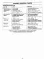
TROUBLE SHOOTING CHART
SYMPTOM
CAUSE
CORRECTION
Engine will not start or
will only run only for a
few seconds after
starting.
1.
2.
3.
4.
5.
6.
1.
2.
3.
4.
5.
6.
Engine will not idle
properly.
1. Carburetor set too fast or too slow.
2. Carburetor requires adjustment.
3. None of the above.
1. See "Carburetor Adjustments."
2. See "Carburetor Adjustments."
3. Contact your SEARS Service Center/Dept.
Engine will not
accelerate, lacks
power, or dies
under a load.
1.
2.
3.
4.
5.
1.
2.
3.
4.
5.
Engine smokes
excessively.
1. Air filter dirty.
2. Fuel mixture incorrect.
3. Carburetor requires adjustment.
1. Clean or replace air filter.
2. Refuel with correct fuel mixture.
3. See "Carburetor Adjustments."
Engine runs hot.
1.
2.
3.
4.
1.
2.
3.
4.
Fuel tank empty.
Engine flooded.
Spark plug not firing.
Fuel not reaching carburetor.
Carburetor requires adjustment.
None of the above.
Air filter dirty.
Spark plug fouled.
Carburetor requires adjustment.
Muffler outlets plugged.
None of the above.
Fuel mixture incorrect.
Spark plug incorrect.
Carburetor set too lean.
None of the above.
Fill tank with correct fuel mixture.
See "Starting Instructions."
Install new plug/check ignition switch.
Replace fuel filter; inspect fuel line.
See "Carburetor Adjustments:'
Contact your SEARS Service Center/Dept.
Clean or replace air filter.
Replace spark plug.
See "Carburetor Adjustments."
Contact your SEARS Service Center/Dept.
Contact your SEARS Service Center/Dept.
See "Fueling Your Unit."
Replace with correct plug.
See "Carburetor Adjustments."
Contact your SEARS Service Center/Dept.
/( situations occur which are not covered in this manual, use care and good judgement.
/( you need assistance, contact your SEARS Service Center/Department or the
CUSTOMER ASSISTANCE HELPLINE at 1-800-235-5878.
-22-
I
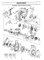
REPAIR PARTS
Sears Blower - Models 358.798960 & 358.798980
2
#3-'
6
23
41 42
~.~~
~~
- (
1!
~46
47
48
94
4~
-
78
81""
87 J'la-f-f!'_
8889
al
~
107
t
~
108
I Arrestor
92
Spark
~
104
23
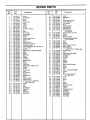
REPAIR PARTS
Key
No.
Part
No.
1
2
3
4
5
6
7
8
9
10
11
12
13
14
15
16
17
18
19
20
21
22
23
24
25
26
27
28
29
30
31
32
33
34
35
36
37
38
39
40
41
42
43
44
45
46
47
48
530-094712
530-026994
530-029111
530-015635
530-029130
530-015813
530-029072
530-027597
530-015702
530-029117
530-015840
530-024772
530-047746
530-047756
530-019168
530-069718
530-029129
530-029089
530-015814
530-047747
530-014347
530-014362
530-014160
530-029728
530-029112
530-047754
530-069293
530-029116
530-030075
530-001624
530-069626
530-039194
530-039137
530-015816
530-019178
530-025875
530-069349
530-015162
530-015306
530-039196
530-015849
530-015254
530-015852
530-035406
530-015771
530-037492
530-029115
530-069730
49
50
51
52
53
54
55
56
530-019164
530-019165
530-015775
530-029113
530-047696
530-019166
530-027593
530-027594
Description
Handle
Front Isolator
Spacer
Screw
Rear Isolator
Screw
Trigger
Spring
"COO
Clip
Throttle Lock Sutton
Pin
Spring
Shroud-Left
Shroud-Right
Grommet
Switch
Isolator-Engine Mount
Isolator-Tank
Screw
Fuel Tank Ass'y.
Fuel Cap (Incl. O'Ring)
Fuel Pick-up Ass'y.
Handle Cover Ass'y, (Incl. #9,10 & 12)
Cover-Air Filter
Air Filter
Assist Handle - Model 358.798980
Muffler
Spring
Spark Plug
Screw
Cylinder
Lead Wire
Ignition Module
Screw
Gasket
Piston Ring
Piston Kit (lncl, #36,38, & Pin)
Retainer
Screw
Ground Wire
Screw
Wave Washer
Spacer
Choke Shutter
Screw
Cable Assembly
Plate-Air Filter
Carburetor Ass'y. (WA219-S)
(lncl. Limiter Cap)
Gasket
Seal
Screw
Ground Wire
Reed Siock
Gasket
Reed Valve
Reed Stop
Key
No.
Part
No.
57
58
59
60
61
62
63
64
65
66
67
530-016064
530-047669
530-015126
530-010960
530-047757
530-032103
530-015787
530-019158
530-032102
530-015789
530-014016
68
69
70
71
72
530-039189
530-347987
530-023817
530-047701
530-047705
73
74
75
76
77
78
530-016080
530-015496
530-027523
530-069486
530-029395
530-069714
79
81
82
83
84
85
86
87
88
89
90
91
92
93
94
95
96
97
530-027569
530-015769
530-047782
530-069303
530-029404
530-019167
530-029182
530-015805
530-027523
530-029119
530-094710
530-029173
530-047702
530-029118
530-015843
530-015441
530-001733
530-047736
98
99
100
101
102
103
104
105
106
107
108
109
110
111
112
530-015814
530-047700
530-015667
530-015647
530-015815
530-015672
530-069348
530-069232
530-069751
530-083791
530-069294
530-047721
530-095355
530-023877
530-047854
Description
Screw
Crankshaft
Key
Connecting Rod Ass'y.
Decal-Instruction
Inner Bearing
Ring
Crankshaft Seal
Outer Searing
Retaining Ring
Crankcase Ass'y
(lncl. #62-65)
Flywheel Ass'y, (Incl. #70)
Washer
Spring
Spacer-Flywheel
Crankcase/CrankshaftAssy.
(Inc!. 58, 62-67)
Screw
Screw
Retainer
Starter Pulley (lncl. #73)
Starter Spring
Fan Housing Kit
(lncl. #71,73-77,79,86
Starter Handle
Screw
Cap - Model 358.798960
Muffler Guard
Air Saffle
"O"Ring
Eyelet
Screw
Retainer
Roll Pin
Slower Housing (Upper)
Band
Impeller
Hub
Screw - Model 358,798980
Washer
Nut
Slower Housing (Lower)
(Incl. #99-103)
Screw
Door
Spring
Pin
Screw
Spring
Spark Arrestor Kit
Rope Kit
Line Kit
Operators Manual
Gasket Kit
Purge Bulb
Mulch Slade
Vent Fitting
Vent Fitting
& 105)
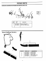
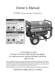
REPAIR PARTS
Carburetor Assembly Part Number 530-069730
(WA219-B)
Carbo
Repair
Kit
,
1
Key
No.
1
2
Part
No.
530-069729
530-038403
Description
Carburetor Repair Kit
Limiter Cap-Single Needle
Vacuum Tube/Blower Tube Ass'y.
4
i
KEY NO.
PART NO.
530-095358
530-037250
530-069750
530-038555
530-095359
1
2
3
4
5
25
i
DESCRIPTION
Collection Bag
Shoulder Strap
Vacuum Tube
Tube & Nozzle Ass'y.
Vac Tube Stand
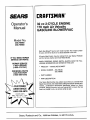
CRAFTSMAN®
SSAiRlS
Operator's
Manual
32 cc 2-CYCLE ENGINE
170 mph Air Velocity
GASOLINE BLOWERNAC
Model No.
358.798960
358.798980
Each Gas Blowers' has its own model number. The model number
for your unit will be found on a decal attached to the unit.
All parts listed herein may be ordered from any Sears, Roebuck
and Co. Service Center and most Retail Stores.
IFYOU NEED REPAIR
SERVICE OR PARTS:
WHEN ORDERING REPAIR PARTS, ALWAYS GIVE THE FOLLOWING INFORMATION AS SHOWN IN THIS LIST:
REPAIR SERVICE
1-800-4-REPAIR
(1-800-473-7247)
ORDERING PARTS
1-800-FON-PART
(1-800-366-7278)
PRODUCT - "GASOLINE BLOWER"
•
MODEL NUMBER - 358.798460
358.798980
•
PART NUMBER
•
PART DESCRIPTION
Your Sears Merchandise has added value when you consider that
Sears has service units nationwide staffed with Sears trained technicians... professional technicians specifically trained on Sears
products, having the parts, tools and squlprnent to insure that we
meet our pledge to you, we service what we sell.
CUSTOMER
ASSISTANCE
1-800-235-5878
HOURS (CST)
Mon. - Sat. 7 a.m. - 7 p.m.
Sun, 10 a.m. - 7 p,m,.
•
l:-
Sears, Roebuck and Co., Hoffman Estates, IL 60179 U.S.A.