1
HP bh5700 ATCA 14-Slot Blade Server
Ethernet Switch Blade
First Edition
Manufacturing Part Number: AD171-9603A
June 2006
Ethernet Switch Blade User's Guide
release 3.2.2j
page ii
Legal Notices
The information in this document is subject to change without notice.
Hewlett-Packard makes no warranty of any kind with regard to this manual, including, but
not limited to, the implied warranties of merchantability and fitness for a particular
purpose. Hewlett- Packard shall not be held liable for errors contained herein or direct,
indirect, special, incidental or consequential damages in connection with the furnishing,
performance, or use of this material.
Restricted Rights Legend. Use, duplication or disclosure by the U.S. Government is subject
to restrictions as set forth in subparagraph (c) (1) (ii) of the Rights in Technical Data and
Computer Software clause at DFARS 252.227-7013 for DOD agencies, and subparagraphs
(c) (1) and (c) (2) of the Commercial Computer Software Restricted Rights clause at FAR
52.227-19 for other agencies.
Information in this document is provided in connection with Intel® products. No
license, express or implied, by estoppel or otherwise, to any intellectual property rights
is granted by this document. Except as provided in Intel’s Terms and Conditions of
Sale for such products, Intel assumes no liability whatsoever, and Intel disclaims any
express or implied warranty, relating to sale and/or use of Intel products including
liability or warranties relating to fitness for a particular purpose, merchantability, or
infringement of any patent, copyright or other intellectual property right. Intel
products are not intended for use in medical, life saving, or life sustaining applications.
Intel may make changes to specifications and product descriptions at any time, without
notice. HEWLETT-PACKARD COMPANY 3000 Hanover Street Palo Alto, California 94304
U.S.A.
Copyright Notice. Copyright ©2003 Hewlett-Packard Development Company, L.P.
Reproduction, adaptation, or translation of this document without prior written
permission is prohibited, except as allowed under the copyright laws.
Additional Copyright Notices. AdvancedTCA® is a registered trademark of the PCI
Industrial Computer Manufacturers Group. Linux® is a registered trademark of Linus
Torvalds. ZNYX Networks, RAIN, RAINlink, OpenArchitect®, CarrierClass and HotSwap
are trademarks or registered trademarks of ZNYX Networks in the United States and/or
other countries. All other marks, trademarks or service marks are the property of their
respective owners.
Ethernet Switch Blade User's Guide
release 3.2.2j
page iii
About the Ethernet Switch Blade Manual
This manual includes everything you need to begin using the HP Ethernet Switch Blade with
OpenArchitect software, Release 3.2.2j.
Ethernet Switch Blade User's Guide
release 3.2.2j
page iv
Table of Contents
Chapter 1 Overview of the Ethernet Switch Blade ...........................................................17
High Performance Embedded Switching...................................................................... 17
Advanced TCA® Compliant.........................................................................................17
OpenArchitect Switch Management............................................................................. 18
Extensible Customization of Routing Policies..............................................................18
Powerful CarrierClass Features.....................................................................................18
Ethernet Port Layout..................................................................................................... 18
Ethernet Switch Blade Port Configuration..................................................................19
Base switch Quick Reference.............................................................................. 19
Fabric Switch Quick Reference........................................................................... 19
OpenArchitect Switch Environment............................................................................. 20
OpenArchitect Software Structure................................................................................ 20
Chapter 2 Port Cabling and LED Indicators...................................................................... 23
Connecting the Cables...................................................................................................23
Console Port Cabling................................................................................................23
Connecting to the Console Port................................................................................23
Out of Band Ports (OOB Ports).................................................................................... 24
LED Reference......................................................................................................... 24
Chapter 3 High Availability Networking...........................................................................27
Surviving Partner.......................................................................................................... 27
VRRP........................................................................................................................28
zlmd.......................................................................................................................... 28
Switch Replacement and Reconfiguration............................................................... 29
zspconfig...................................................................................................................29
Example HA Switch Configuration..........................................................................30
Modifying zsp.conf on the Base switch...............................................................31
Modifying zsp_vlan.conf on the Fabric Switch...................................................35
Configuring Surviving Partner......................................................................................42
Central Authority.......................................................................................................... 43
Chapter 4 Fabric Switch Configuration ............................................................................ 46
Two switches, two consoles..........................................................................................46
Connecting to the Fabric Switch Console.....................................................................46
OpenArchitect Configuration Procedure.......................................................................46
Changing the Shell Prompt........................................................................................... 47
Default Configuration Scripts...................................................................................47
Example Configuration Scripts................................................................................ 47
Overview of OpenArchitect VLAN Interfaces.........................................................48
Tagging and Untagging VLANs..........................................................................48
Switch Port Interfaces..........................................................................................49
Layer 2 Switch Configuration.......................................................................................49
Using the S50layer2 Script.................................................................................. 50
Ethernet Switch Blade User's Guide
release 3.2.2j
page v
Rapid Spanning Tree................................................................................................ 50
To Enable Rapid Spanning Tree:.........................................................................51
Port Path Cost...................................................................................................... 51
Layer 3 Switch Configuration............................................................................. 52
Using the S50layer3 Script.................................................................................. 52
Layer 3 Routing Protocols with GateD ........................................................................54
Using the S55gatedRip1 Script................................................................................ 54
To Modify the GateD Scripts: ................................................................................. 56
Class of Service (COS) ................................................................................................ 57
Egress Queues.......................................................................................................... 57
Ingress Classification................................................................................................57
Marking and Re-marking......................................................................................... 58
Scheduling................................................................................................................ 58
ztmd Explained.................................................................................................... 58
zfilterd Explained..................................................................................................... 58
Running zfilterd........................................................................................................58
Restrictions on Implementation................................................................................59
Conflict Resolution..............................................................................................59
iptables and filtering............................................................................................ 60
Introduction..........................................................................................................60
Packet Walk......................................................................................................... 61
Filter Rules Specifications...................................................................................62
Specifying Source and Destination IP Addresses.................................................... 62
Specifying Protocol............................................................................................. 62
Specifying an ICMP Message Type.................................................................... 62
Specifying TCP or UDP ports............................................................................. 63
Specifying TCP flags...........................................................................................63
Specifying an Interface........................................................................................ 63
Filter Rule Targets............................................................................................... 63
Supported Targets................................................................................................63
Classical Targets..................................................................................................63
ZNYX Targets..................................................................................................... 63
ZACTION Examples........................................................................................... 64
Extensions to the default matches........................................................................64
tc and zqosd ............................................................................................................. 65
FIFO Queues (pfifo and bfifo disciplines)...........................................................65
PRIO and WRR queues....................................................................................... 67
The U32 Filter.......................................................................................................... 69
Combining Queuing Disciplines.............................................................................. 69
Handle Semantics................................................................................................ 70
COPS: Common Open Policy Service..........................................................................70
Protocol Architecture................................................................................................71
OpenArchitect PEP...................................................................................................71
Using pepd................................................................................................................72
Ethernet Switch Blade User's Guide
release 3.2.2j
page vi
Chapter 5 Fabric Switch Administration........................................................................... 73
Setting the Root Password............................................................................................ 73
Adding Additional Users...............................................................................................73
Setting up a Default Route............................................................................................ 74
Name Service Resolution..............................................................................................74
DHCP Client Configuration..........................................................................................74
DHCP Server Configuration......................................................................................... 74
Network Time Protocol (NTP) Client Configuration................................................... 75
Network File System (NFS) Client Configuration........................................................75
NFS Server Configuration.............................................................................................76
Connecting to the Switch Using FTP............................................................................77
ftpd Server Configuration............................................................................................. 77
Connecting to the Switch Using TFTP......................................................................... 77
TFTPD Server Configuration........................................................................................77
SNMP Agent................................................................................................................. 78
Supported MIBS.......................................................................................................78
Supported Traps........................................................................................................79
SNMP and OpenArchitect Interface Definitions......................................................80
ifStackTable Entries.............................................................................................81
SNMP Configuration................................................................................................81
SNMP Applications..................................................................................................82
Port Mirroring............................................................................................................... 82
Link and LED Control.................................................................................................. 83
Link Event Monitoring..................................................................................................83
Chapter 6 Fabric Switch Maintenance...............................................................................84
Overview of the OpenArchitect switch boot process....................................................84
Saving Changes.............................................................................................................86
Modifying Files and Updating the Switch.................................................................... 86
Recovering from a System Failure................................................................................86
System Boots with a Console Cable............................................................................. 86
Booting with the –i option.............................................................................................87
System Hangs During Boot...........................................................................................88
Booting the Duplicate Flash Image...............................................................................88
Upgrading the OpenArchitect Image............................................................................ 88
Upgrading or Adding Files............................................................................................89
Excluding Saving Files to Flash............................................................................... 89
Upgrading the Switch Driver........................................................................................ 89
Using apt-get................................................................................................................. 90
Chapter 7 Base Switch Configuration................................................................................91
Two switches, two consoles..........................................................................................91
Connecting to the Base Switch Console....................................................................... 91
OpenArchitect Configuration Procedure..................................................................91
Changing the Shell Prompt.......................................................................................92
Default Configuration Scripts..............................................................................92
Ethernet Switch Blade User's Guide
release 3.2.2j
page vii
Example Configuration Scripts............................................................................92
Overview of OpenArchitect VLAN Interfaces....................................................93
Tagging and Untagging VLANs..........................................................................94
Switch Port Interfaces..........................................................................................94
Layer 2 Switch Configuration.................................................................................. 94
Using the S50layer2 Script.................................................................................. 96
Rapid Spanning Tree................................................................................................ 96
To Enable Rapid Spanning Tree:.........................................................................96
Port Path Cost...................................................................................................... 97
Layer 3 Switch Configuration.................................................................................. 97
Using the S50layer3 Script.................................................................................. 98
Layer 3 Switch Using Multiple VLANs............................................................100
Using the S50multivlan Script...........................................................................100
To Modify the Layer 3 Multivlan Script ......................................................... 102
Modify the example script you copied into the /etc/rcZ.d directory. Adjust and
assign the number of IP addresses as applicable. In the example below, the IP
address is changed for the interface in the ifconfig command line of the script.
........................................................................................................................... 102
Layer 3 Routing Protocols with GateD ................................................................. 102
Using the Provided S55gatedRip1 Script.......................................................... 102
To Modify the GateD Scripts: .......................................................................... 104
Class of Service (COS) ..........................................................................................105
Egress Queues....................................................................................................105
Ingress Classification.........................................................................................105
Marking and Re-marking...................................................................................106
Scheduling......................................................................................................... 106
zcos......................................................................................................................... 106
zfilterd.....................................................................................................................106
ztmd................................................................................................................... 106
Running zfilterd................................................................................................. 107
Restrictions on Implementation.........................................................................107
Conflict Resolution............................................................................................107
iptables and filtering............................................................................................... 108
Introduction........................................................................................................109
Packet Walk....................................................................................................... 110
Filter Rules Specifications.................................................................................110
Specifying Source and Destination IP Addresses..............................................110
Specifying Protocol........................................................................................... 110
Specifying an ICMP Message Type.................................................................. 110
Specifying TCP or UDP ports........................................................................... 111
Specifying TCP flags.........................................................................................111
Specifying an Interface...................................................................................... 111
Filter Rule Targets............................................................................................. 111
Supported Targets..............................................................................................111
Ethernet Switch Blade User's Guide
release 3.2.2j
page viii
Classical Targets................................................................................................111
ZNYX Targets................................................................................................... 112
ZACTION Examples......................................................................................... 112
Extensions to the default matches......................................................................113
tc: Traffic Control..................................................................................................113
Strict Priority Qdisc................................................................................................113
Weighted Round Robin Qdisc................................................................................114
FIFO Queues (pfifo and bfifo disciplines).........................................................114
Fifo Qdiscs..............................................................................................................115
Using Filters to Direct Packets to a COS Queue....................................................115
Protocol ip.............................................................................................................. 115
Protocol arp............................................................................................................ 116
Protocol all..............................................................................................................116
Matching Specific Ingress Ports.............................................................................116
Advanced Filtering – Policing................................................................................117
Examples............................................................................................................118
Policing Actions..................................................................................................... 118
u32 match selectors used in filters.........................................................................119
zqosd.......................................................................................................................120
PRIO and WRR queues..................................................................................... 121
The U32 Filter........................................................................................................ 123
Combining Queuing Disciplines............................................................................ 124
Handle Semantics.............................................................................................. 124
COPS: Common Open Policy Service................................................................... 124
Protocol Architecture.........................................................................................125
OpenArchitect PEP............................................................................................126
Using pepd......................................................................................................... 126
Chapter 8 Base Switch Administration............................................................................128
Setting the Root Password......................................................................................128
Adding Additional Users........................................................................................128
Setting up a Default Route..................................................................................... 129
Name Service Resolution....................................................................................... 129
DHCP Client Configuration................................................................................... 129
DHCP Server Configuration...................................................................................129
Network Time Protocol (NTP) Client Configuration.............................................130
Network File System (NFS) Client Configuration.................................................130
NFS Server Configuration......................................................................................131
Connecting to the Switch Using FTP..................................................................... 131
ftpd Server Configuration.......................................................................................132
Connecting to the Switch Using TFTP...................................................................132
TFTPD Server Configuration................................................................................. 132
SNMP Agent.......................................................................................................... 132
Supported MIBS................................................................................................ 132
Supported Traps.................................................................................................134
Ethernet Switch Blade User's Guide
release 3.2.2j
page ix
SNMP and OpenArchitect Interface Definitions............................................... 134
ifStackTable Entries...........................................................................................135
SNMP Configuration......................................................................................... 135
SNMP Applications........................................................................................... 136
Port Mirroring.........................................................................................................136
Link and LED Control............................................................................................137
Link Event Monitoring........................................................................................... 137
Chapter 9 Base Switch Maintenance............................................................................... 138
Overview of the OpenArchitect switch boot process............................................. 138
Saving Changes...................................................................................................... 140
Modifying Files and Updating the Switch..............................................................140
Recovering from a System Failure......................................................................... 140
System Boots with a Console Cable.......................................................................140
Booting with the –i option......................................................................................141
System Hangs During Boot.................................................................................... 142
Booting the Duplicate Flash Image........................................................................ 142
Upgrading the OpenArchitect Image......................................................................142
Upgrading or Adding Files.....................................................................................143
Excluding Saving Files to Flash............................................................................. 143
Upgrading the Switch Driver..................................................................................143
Using apt-get.......................................................................................................... 144
Chapter 10 Connecting to the Ethernet Switch Blade..................................................... 145
Base Interface Hub System:........................................................................................ 145
Ethernet Interfaces: ................................................................................................145
Management Interfaces: ........................................................................................ 145
Fabric Interface Hub System: .....................................................................................146
Ethernet Interfaces: ................................................................................................146
Management Interfaces: ........................................................................................ 146
Connecting to the Base Interface................................................................................ 146
Base Interface Serial Port Connection....................................................................146
Base Interface Out-of-Band Ethernet Connection .................................................147
Connecting to the Fabric Interface .............................................................................148
Fabric Interface Serial Port Connection ................................................................ 148
Fabric Interface Out of Band Ethernet Connection ...............................................149
Chapter 11 Diagnosing a Failed Ethernet Switch Blade Activation ..............................150
Accessing the ShMM.................................................................................................. 152
Verifying Communications Between the ShMM and Switch................................ 152
Critical Threshold Error Reported..................................................................... 152
Analyzing Mstate information for the switch............................................................. 153
Checking the ekey Status From the Shelf Manager.................................................... 153
Chapter 12 Troubleshooting a Failed OpenArchitect Load.............................................155
Recovering from a System Failure .............................................................................157
Booting Without the Overlay File...............................................................................158
Ethernet Switch Blade User's Guide
release 3.2.2j
page x
Booting the Duplicate Flash Image ............................................................................159
Chapter 13 Network Configuration Problems ............................................................... 160
Interface Overview......................................................................................................160
Physical Interfaces..................................................................................................160
Default Base Interface Configuration.....................................................................161
24 port, Layer 2 Switching, single VLAN.........................................................161
Default Fabric Interface Configuration.................................................................. 163
Editing the S50layer2 script can change the Ethernet Switch Blade Fabric Interface
default configuration. The S50Layer2 script and included example scripts
(/etc/rcZ.d/examples) can be used as templates to create custom scripts. The default
S50layer2 script configures the switch accordingly:..............................................163
Configuration Troubleshooting...................................................................................165
Determining ekey status for a specific slot................................................................. 165
Querying Base Interface ekey Status......................................................................167
Querying Fabric Interface ekey Status................................................................... 168
Network Connectivity Troubleshooting......................................................................170
No Connection........................................................................................................170
Diminished Network Throughput...........................................................................170
Connecting to Devices with Fixed Port Speeds ......................................................... 170
External Fault LED..................................................................................................... 170
Network Tests............................................................................................................. 171
Ping Test ................................................................................................................171
Traceroute Test.......................................................................................................172
Chapter 14 Isolating Hardware Failures.......................................................................... 173
Hardware Subsystem...................................................................................................176
Testing the FlashROMs...............................................................................................177
Testing the Switch Fabric............................................................................................178
Link Status for a single port................................................................................... 178
Link Status for a range of ports.............................................................................. 178
Testing the onboard RAM...........................................................................................179
Testing the Control Processor..................................................................................... 180
Hardware Fault....................................................................................................... 181
Software Error................................................................................................... 181
Chapter 15 High Availability Troubleshooting............................................................... 183
Spontaneous Failover Activity....................................................................................183
Unexpected Fail-back Activity...............................................................................183
Chapter 16 Switch Firmware Overview.......................................................................... 184
Checking the switch firmware version........................................................................184
3.1 Fabric Interface............................................................................................185
Updating the Switch Firmware................................................................................... 186
BootLoader Firmware Upgrade:.............................................................................186
OpenArchitect Firmware Upgrade:........................................................................ 186
IPMC Firmware Upgrade:......................................................................................187
Ethernet Switch Blade User's Guide
release 3.2.2j
page xi
Chapter 17 Restoring the Factory Default Configuration................................................188
Chapter 18 Before Calling Support..................................................................................189
Appendix A Fabric Switch Command Man Pages........................................................ 191
vrrpconfig ...................................................................................................................192
vrrpd ........................................................................................................................... 194
zbootcfg ......................................................................................................................197
zconfig ........................................................................................................................199
zcos .............................................................................................................................207
zdog ............................................................................................................................211
zfilterd ........................................................................................................................ 213
zflash........................................................................................................................... 214
zl2, zl2mc, zl3host, zl3net, zvlan................................................................................ 216
zgvrpd .........................................................................................................................219
zl2d .............................................................................................................................221
zl3d .............................................................................................................................223
zlc ............................................................................................................................... 225
zlmd ............................................................................................................................228
zlogrotate ....................................................................................................................230
zmirror ........................................................................................................................231
zmnt.............................................................................................................................233
zpeer ........................................................................................................................... 235
zqosd .......................................................................................................................... 238
zrc ...............................................................................................................................240
zreg..............................................................................................................................241
zrld ............................................................................................................................. 243
zsnoopd ...................................................................................................................... 244
zspconfig .................................................................................................................... 246
zstack ..........................................................................................................................253
ztats............................................................................................................................. 258
zsync............................................................................................................................259
ztmd ............................................................................................................................261
brctl(8) ........................................................................................................................263
Appendix B Base Switch Command Man Pages...........................................................266
vrrpconfig ...................................................................................................................267
vrrpd ........................................................................................................................... 269
zbootcfg ......................................................................................................................272
zconfig ........................................................................................................................274
zcos .............................................................................................................................282
zdog ............................................................................................................................286
zffpcounter ................................................................................................................. 288
zfilterd......................................................................................................................... 292
zflash........................................................................................................................... 293
zgmrpd........................................................................................................................ 295
Ethernet Switch Blade User's Guide
release 3.2.2j
page xii
zgr................................................................................................................................297
zgvrpd..........................................................................................................................300
zl2d..............................................................................................................................302
zl3d..............................................................................................................................304
zlc ............................................................................................................................... 306
zlmd ............................................................................................................................308
zlogrotate ....................................................................................................................310
zmirror ........................................................................................................................311
zmnt.............................................................................................................................314
zpeer ........................................................................................................................... 316
zqosd........................................................................................................................... 319
zrc ...............................................................................................................................321
zreg..............................................................................................................................322
zrld ............................................................................................................................. 324
zsnoopd ...................................................................................................................... 325
zspconfig .................................................................................................................... 328
zstack ..........................................................................................................................336
ztats............................................................................................................................. 340
zsync............................................................................................................................341
ztmd.............................................................................................................................343
brctl(8).........................................................................................................................345
Appendix C Intelligent Platform Management Interface ..............................................348
ISwitch-ShMC Interaction.......................................................................................... 348
Peripheral Management Controller Functional Support............................................. 349
Sensor Reading Example........................................................................................350
Structure of Standard IPMI Commands: From BMC to PMC....................................352
Structure of Standard IPMI Responses: From PMC to BMC..................................... 352
Event Generator ........................................................................................................ 353
IPMB Event message format............................................................................. 353
IPMI Event Message Definitions.......................................................................353
Field Replaceable Unit Inventory Device.............................................................. 353
IPMB Override/Local Status - Event Data 3 for the IPMB link........................354
Table of Figures
Figure 1.1: Fabric Switch Elements...................................................................................20
Figure 1.2: OpenArchitect Software Structure.................................................................. 22
Figure 2.1: LED Reference................................................................................................ 25
Figure 3.1: Host HA Architecture......................................................................................27
Figure 4.1: Fabric VLANs................................................................................................. 48
Figure 4.2: Firewall Flow ................................................................................................ 61
Figure 4.3: COPS Network Architecture........................................................................... 70
Figure 6.1: ROM Devices in Open Architect.................................................................... 84
Figure 6.2: Boot Flow Chart.............................................................................................. 85
Ethernet Switch Blade User's Guide
release 3.2.2j
page xiii
Figure 6.3: Init Script Flow................................................................................................86
Figure 7.1: Multiple VLANs..............................................................................................94
Figure 7.2: Layer 2 Switch ................................................................................................95
Figure 7.3: Layer 3 Switch ................................................................................................99
Figure 7.4: Multiple VLAN Configuration......................................................................101
Figure 7.5: Firewall Flow ............................................................................................... 109
Figure 7.6: COPS Network Architecture........................................................................ 125
Figure 9.1: ROM Devices in OpenArchitect................................................................... 138
Figure 9.2: Booting up Process Flow..............................................................................139
Figure 9.3: Init Script Flow..............................................................................................140
Figure 10.1: Fabric and Base .......................................................................................... 145
Figure 10.2: Base Interface Serial Port............................................................................ 147
Figure 10.3: Fabric Interface Serial Ports........................................................................ 148
Figure 11.1: Ethernet Switch Blade Activation States.....................................................150
Figure 12.1: OpenArchitect Boot Process....................................................................... 156
Figure 12.2: ROM Devices in OpenArchitect................................................................. 157
Figure 18.1: ROM Devices in OpenArchitect................................................................. 190
Index of Tables
Table 5.1: Supported MIBs................................................................................................79
Table 5.2: Supported Traps................................................................................................80
Table 5.3: Link and SNMP Status..................................................................................... 81
Table 7.1: Port Path Cost................................................................................................... 97
Table 7.2: Policing Actions..............................................................................................119
Table 7.3: U Match Selectors...........................................................................................120
Table 8.1: Supported MIBs..............................................................................................134
Table 8.2: Supported Traps..............................................................................................134
Table 8.3: Physical Link Status on Base Switch..............................................................135
Table 11.1: Troubleshooting States................................................................................. 152
Table 13.1: Ethernet Switch Blade Backplane Interfaces (zre Ports)..............................160
Table 13.2: Additional Interfaces.................................................................................... 161
Table C.1.: IPMI M States............................................................................................... 349
Table C.2: PMC Controller Support................................................................................ 349
Table C.3: GetSensorReading..........................................................................................350
Table C.4: GetSensorResonse..........................................................................................351
Table C.5: Standard IPMI Commands.............................................................................352
Table C.6: Standard IPMI Responses.............................................................................. 352
Table C.7: Event Message Format...................................................................................353
Table C.8: SEEPROM Space...........................................................................................354
Table C.9.: IPMB Override Status Data.......................................................................... 355
Ethernet Switch Blade User's Guide
release 3.2.2j
page xiv
Ethernet Switch Blade User's Guide
release 3.2.2j
page 15
Ethernet Switch Blade User's Guide
release 3.2.2j
page 16
Chapter 1 Overview of the Ethernet Switch Blade
The Ethernet Switch Blade is a 72-port AdvancedTCA® Hub and providing Gigabit Ethernet.
Up to 14 ATCA node boards may be addressed via the PICMG 3.0 Base Interface and via the
ATCA PICMG 3.1 fabric . The Base and Fabric switching domains are kept totally separate, both
on the physical layer and the software layer. The Ethernet Switch Blade provides a tightly
integrated modular switching platform that enables high-density solutions.
The Ethernet Switch Blade is actually two separate switches, one for the Base ports and one for
the fabric ports. There are two OpenArchitect® operating system images, one for each switch,
allowing the maximum in separation between the control signaling and the data. The modular
design provides great flexibility and control.
Ethernet Switch Blades can support a 10 Gigabit Ethernet Inter-Switch Link (ISL) for the Fabric
Interfaces, and a Gigabit Ethernet ISL for the Base Interface switches. Depending on the version
of OpenArchitect used, the ISL for the Fabric Interface switches may be operated at 10 Gigabits
per second and provide stacking features.
Linux-based OpenArchitect 3 runs on the embedded processors, providing a comprehensive
package for the management of Layer 2 and Layer 3 packet switching. VLAN management and
Layer 2-7 packet classification are also included with a user-friendly interface. OpenArchitect can
be used with a variety of IP routing protocols.
As part of Advanced TCA, the switch incorporates the PICMG 3.0 Intelligent Platform
Management Interface (IPMI) standard for Field Replaceable Unit FRU) management by the
Shelf Manager.
High Performance Embedded Switching
The Ethernet Switch Blade with OpenArchitect combines the performance of silicon-based
switching fabric with flexibility of software-managed routing policies. It provides Base fabric
PICMC 3.0 (1 Gigabit Ethernet ) links to each of the payload slots, plus two to four PICMC 3.1
in-band GigE ports to each node card, and GigE links to management ports and the second
switch. The Ethernet Switch Blade maintains the forwarding table on silicon, providing the
capability to switch and route at full line rate performance on every port.
Advanced TCA® Compliant
The Advanced TCA® standard developed by the PCI Industrial Computer Manufacturer Group
defines an embedded Ethernet environment for high availability chassis. This environment
includes two switch fabric slots that create a dual star Ethernet network to the 14 Base node slots.
Placing the Ethernet Switch Blade in a hub slot provides embedded Ethernet services to each
node card of the chassis. A standard HA configuration is one Ethernet Switch Blade placed in
each of the two hub slots in a chassis for creation of a redundant, high availability system.
Ethernet Switch Blade User's Guide
release 3.2.2j
page 17
OpenArchitect Switch Management
The OpenArchitect software component – open source Linux, IP protocol stack, control
applications and the OA Engine – runs on two embedded PowerPC microprocessors.
OpenArchitect provides extensive managed IP routing protocols and other open standards for
switch management. Examples include network services; Virtual Redundant Router Protocol;
Routing Information Protocol; Open Shortest Path First; Border Gateway Protocol; Quality of
Service and Class of Service; access control lists; Simple Network Management Protocol MIBs,
Common Open Policy Services and web.
Extensible Customization of Routing Policies
The OpenArchitect software environment enables rapid porting of other UNIX/Linux-based
protocols, including open source software conforming to RFCs and other standards. It also
enables the development of application-specific protocol configuration scripts.
Powerful CarrierClass Features
The Ethernet Switch Blade has High Availability hardware features for advanced
telecommunication applications. The switch implements the PICMG 3.0 Full Hotswap support.
This feature provides field replaceable capabilities so a switch can fail and be replaced without
impacting the operational performance of a chassis.
The PICMG 3.0 Intelligent Platform Management Interface (IPMI) standard is also supported.
IPMI uses message-based interfaces that monitor the physical health characteristics of the
Ethernet Switch Blade. The switch provides operational status information to an IPMI
management application. End customers benefit with advanced notice of potential problems.
The Ethernet Switch Blade also implements the Media Dependent Interface called Auto MDI-X.
Auto MDI-X allows connections to any device, switches, hubs, or systems using a regular
straight-through or crossover Cat 5 cable. The RJ-45 port will auto detect and switch MDI/MDIX modes. This IEEE standard makes cabling – especially between switches – faster and less error
prone.
E-Keying is supported by the Ethernet Switch Blade.
Ethernet Port Layout
The Ethernet Switch Blade has a total of 72 switched Gigabit Ethernet ports. The base fabric is
connected via 24 Gigabit Ethernet ports and the data fabric is connected via 48 Gigabit Ethernet
ports. The Ethernet Switch Blade is actually composed of two separate switches, one for Base
port activity and another for fabric port activity. The Base ports ( control and signaling) are
switched on the Base switch, and the fabric ports ( data ) are switched on the fabric switch, which
provides total separation between system management or control packets, and customer data
packets.
Ethernet Switch Blade User's Guide
release 3.2.2j
page 18
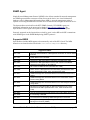
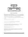
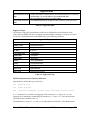
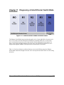
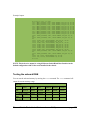
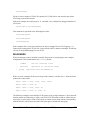
Ethernet Switch Blade Port Configuration
Base switch Quick Reference
ShelfManager1
zre22
ShelfManager2
zre13
ISL channel ( Base node2 )
zre23
Base nodes 3-14
zre0-11
Base nodes 15,16
zre 20-21
Front panel
zre12, zre14, zre15
Fabric Switch Quick Reference
slot
zre numbers
3
zre0-3
4
zre4-7
5
zre8-11
6
zre12-15
7
zre16-19
8
zre24-27
9
zre28-29
10
zre30-31
11
zre32-33
12
zre34-35
13
zre36-37
14
zre38, zre39
15
zre40-41
16
zre42-43
Inter-switch Link (ISL)
zre51
Front panel
zre20-23
Ethernet Switch Blade User's Guide
release 3.2.2j
page 19
You will find the Ethernet Switch Blade has a straightforward installation and configuration.
UNIX or Linux system management skills and some understanding of network protocols will be
required. Configure the Ethernet Switch Blades to your networking application before you
begin using the OpenArchitect switch.
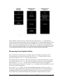
OpenArchitect Switch Environment
The key elements of the OpenArchitect environment include two embedded Linux operating
systems, OpenArchitect-specific applications and libraries, plus, an innovative switch hardware
design.
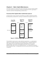
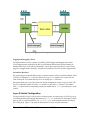
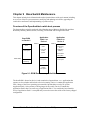
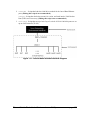
OpenArchitect hardware is in many ways similar to typical switch architectures. The primary
difference in OpenArchitect is that the PCI bus that interfaces with the embedded processor and
the switch fabric is at a higher performance level than a typical switch (see Figure 1.1: Fabric
Switch Elements). The use of PCI creates a pipe of significant bandwidth between the processor
and the switch fabric.
The embedded processors, running Linux and the OpenArchitect processes, control the flow of all
traffic by maintaining the switch forwarding tables. These tables define the flow of the switch
traffic. Because they are on the switching chips, packets proceed at line rate.
OpenArchitect Software Structure
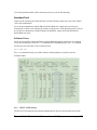
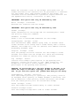
Figure 1.1: Fabric Switch Elements
OpenArchitect is based on an embedded Linux operating system and includes a number of ZNYX
Networks-supplied modules. The key element is the Linux routing table, which is crucial in a
Ethernet Switch Blade User's Guide
release 3.2.2j
page 20
network-enabled Linux implementation.
The purpose of the routing table is to tell the packet forwarding software where to forward the
data packets. In Linux, the packet-forwarding algorithm is operated in software. Normally, the
routing tables are maintained by operator configuration and the various routing protocols that run
in the application environment of Linux.
OpenArchitect uses an innovative new approach for forwarding packets. It provides embedded
software daemons that replicate ( shadow) the Linux routing tables in the silicon-based
forwarding tables (see Figure 1.1: Fabric Switch Elements). In the OpenArchitect switching
environment, the switching chips do the real-time work in switching network packets. The switch
fabric consults its own forwarding tables for each incoming packet; and either filters or forwards
the packet to any egress port, the embedded CPU, or to any combination. The Linux routing
tables, running in software, are used to update the silicon-based tables. This provides both the
flexibility and control of the Linux software environment and the speed of dedicated switching
silicon.
The OpenArchitect environment includes additional features. For example, installing the
OpenArchitect switch gives you immediate implementation of Linux routing protocols. Also, you
have complete support of routing table updates and a standardized method for configuration.
Finally, you can quickly integrate bug fixes, protocol enhancements and additional protocol
implementations from the Linux community. You can also integrate OpenArchitect into other
Linux applications including VPN software, voice over IP protocols, Quality of Service, and
HTML configuration.
RAIN Management API (RMAPI) is a generic interface for passing control data. The
OpenArchitect libraries are implemented completely above RMAPI. The libraries provide a frontend to RMAPI to simplify application writing. Currently one library is implemented, a general
library called zlxlib. As the OpenArchitect application requirements grow, the existing library
will be expanded and additional libraries will be created.
Ethernet Switch Blade User's Guide
release 3.2.2j
page 21
Linux
Application
Environment
OpenArchitect Application Level Software
(i.e., zconfig, zl3d, zl2d, zsync)
OpenArchitect Libraries
zlxlib and ztlib
Linux Application
Level Software
(routed, gated)
Linux
Kernel
Linux
Protocol
Stack
ZNYX RAIN Mgt API RMAPI
Linux
Routing
Tables
Open Architect Driver
PCI Bus
Switch
Fabric
Figure 1.2: OpenArchitect Software Structure
OpenArchitect applications are used to program and configure the Ethernet Switch Blade. These
applications are implemented above the libraries and RMAPI.
Ethernet Switch Blade User's Guide
release 3.2.2j
page 22
Chapter 2 Port Cabling and LED Indicators
The PICMG 3.1 standard defines an embedded Ethernet environment for Telco chassis. This
environment includes two switch fabric slots that create a dual star Ethernet network to the
fourteen node slots. Placing the Ethernet Switch Blade in a hub slot provides embedded Ethernet
services to each node card across the Packet Switching Backplane of the chassis. A standard
configuration is to place a Ethernet Switch Blade in each hub slot creating a redundant, high
availability system. This chapter provides information on the Ethernet Switch Blade port
connectors and LED indicators.
Connecting the Cables
Your switch setup may require some or all of the following types of cables: 10/100/1000 Port
Cabling
Category 5 cabling is required for all external ports. Be sure that your cable length is within the
minimum and maximum length restrictions for the Ethernet, otherwise you could experience
signal or data loss. All copper GigE ports on the Ethernet Switch Blade are auto-MDI sensing
and will automatically determine whether or not an MDI (straight-through) or MDI-X (crossover)
cable is attached.
Console Port Cabling
The switch console can be accessed via one RJ-45 10/100 service port located on the front panel
of the Ethernet Switch Blade.
NOTE: There are two switch portions that make up a Ethernet Switch Blade unit. Each
switch portion, Base and fabric, has its own console ports, and requires its own console
cable or OOB Ethernet cable.
The RS-232 configured RJ-45 connector console port on the front panel can be used to recover
from a system failure. It is used for maintenance only, and is generally not connected. Use a HP
console cable (P/N A6900-63006) provided with the HP bh5700 ATCA 14-Slot Blade Server, in
combination with a Modem Eliminator cable, to access the switch software through the console
port. Refer to the HP bh5700 ATCA 14-Slot Blade Server Installation Guide for additional
information.
Connecting to the Console Port
To attach the console cable to the OpenArchitect Base or fabric switch:
1. Plug the RJ-45 end of the console cable into the RJ-45 Console Port on the front.
2. Connect the Modem Eliminator cable to the DB-9 connector on the console cable.
3. Connect the other end of the Modem Eliminator cable to a standard COM port (9600, n,
8, 1).
Ethernet Switch Blade User's Guide
release 3.2.2j
page 23
4. Reinsert the switch into the shelf chassis and power up.
Use a terminal emulation program to access the switch console.
Out of Band Ports (OOB Ports)
Each switch, fabric and Base, in a Ethernet Switch Blade unit has out-of-band (OOB) Ethernet
ports on the front panel. This is an alternative maintenance port supplying Ethernet connectivity
instead of serial connectivity and is connected only when performing switch maintenance
activities. Use ifconfig to bring up and configure the OOB ports. The OOB ports are 100 full
duplex, not auto-sensing. The front OOB port is eth0, and the rear (not implemented with this
release) is eth1.
LED Reference
See Figure 2.1 for a schematic view of the front of a typical Ethernet Switch Blade board. Note
that there are out-of-band ports, RS232 ports, a USB port, and 10 Gig egress ports (not
implemented in this release). In-band ports from the Base and fabric switches have LED status
lights controlled from the LED Mode button. Press the button successively to display the Base
switch ports, fabric switch ports 0-23, and finally the fabric switch ports 24-47. There are
separate LEDs for the out-of-band ports, and the ATCA status functions.
Ethernet Switch Blade User's Guide
release 3.2.2j
page 24
Figure 2.1: LED Reference
Ethernet Switch Blade User's Guide
release 3.2.2j
page 25
Ethernet Switch Blade User's Guide
release 3.2.2j
page 26
Chapter 3 High Availability Networking
High availability networking is achieved by eliminating any single point of failure through
redundant connectivity: Redundant cables, switches and network interfaces for hardware,
combined with HA software solutions on both the hosts and switches to control the HA hardware
and maintain connectivity. An HA solution called Surviving Partner is provided on the switch.
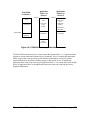
For host-side HA, the most common solution is to use the Linux bonding driver. HA solutions
like the Linux bonding driver present a single, virtual interface to the protocol stack while
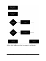
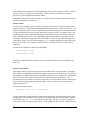
managing multiple physical links. Figure 3.1: Host HA Architecture shows the relation of the
protocol stack, a bonding driver and physical ports.
Figure 3.1: Host HA
Architecture
A failover between physical links can be made very quickly without requiring change to the IP or
MAC address of the virtual interface, effectively transparent from the applications point of view.
With redundant links from a switch (or switches) to the host, one link is maintained as the
ACTIVE link and the other as STANDBY. If the ACTIVE link were to go down, the STANDBY
becomes the new ACTIVE, while presenting the same virtual interface to the host.
NOTE: It is important that the bonding solution provide an active-backup mode. For the
Linux bonding driver set “mode == 1” see the http://sourceforge.net/projects/bonding/
documentation for more information. Use the recommendations for Linux kernel 2.4x not
2.6x.
Redundant connections provide an ACTIVE and STANDBY link to a switch, or provide
redundant links between more than one switch. In the case of more than one switch, a complete
HA solution requires a switch-based HA solution.
Surviving Partner
Surviving Partner is a switch-based HA solution. Surviving Partner runs on the switches to
provide transition of Layer 2 and Layer 3 switching functionality between two or more switches.
Surviving Partner is comprised of many interactive protocols and processes including VRRP,
zlmd, zlc, and others.
Ethernet Switch Blade User's Guide
release 3.2.2j
page 27
VRRP
Since most end nodes use default router addresses, the change of the default router address during
a switch failover would require the end nodes to reconfigure. Layer 3 switches that failover must
maintain the default router address to maintain the end node's IP transparent failover. The Virtual
Router Redundancy Protocol (VRRP, RFC 2338) running in the Surviving Partner switches
provides transparent movement of the default router address. VRRP maintains the notion of a
Master switch and one or more Backup switches. This group of switches presents a virtual router
IP address that can be used by hosts on that net as their default route.
If a Backup switch determines the Master switch is no longer available, one of the Backup
switches will assume the role as Master. Physically, each switch maintains a link to the local
network. Only the Master switch answers to the default gateway, and the hosts on that net have
no need to relearn the router address.
In an HA configuration, the goal is to avoid any single point of failure. VRRP provides a good
mechanism to provide a static route for a local network, but a true HA configuration must also
provide redundant connections for the host. Providing a virtual router for the local network is not
enough. Take the simple case of two hosts on the local network with a connection to the virtual
router. Each host needs a connection to each physical switch participating in VRRP. In the
simplest configuration, each host would have one connection to the network. An HA solution
would include redundant connections from each host to each switch in the virtual router.
Combining the features of Surviving Partner on the switches and HA bonding drivers on the hosts
allows implementation of this true HA configuration.
zlmd
In addition to complete switch failover, single link failure must be properly handled. The Link
Monitor Daemon zlmd, monitors the link status of each port. If a link goes down, zlmd
communicates with the VRRP daemon (vrrpd) to change its priority. Changing the VRRP
priority results in movement of switching functionality. By combining zlmd with the zlc
application, links connected to hosts that have not failed can be deterministically moved to the
new master switch if desired. Supported modes include:
•
switch - The switch with the greatest number of UP links becomes the Master for all
VLANs under HA management.
•
Vlan - The switch with the greatest number of UP links in that particular VLAN becomes
the Master for that particular VLAN. If the switch has additional VLANs, they each
change independently.
•
Port - The Master will remain the Master for that particular VLAN until all ports in that
VLAN are down. The Backup then becomes the new Master for that VLAN. Failed links
move their connectivity through the Backup Switch and the switch interconnect to reach
the Master Switch. This option alleviates the need to move all nodes to a new switch just
because a single link goes down.
NOTE: All modes require inclusion of the interconnect in the VLAN. The ISL
connection between the two Base switches is port 23 for the Ethernet Switch Blade. The
ISL connection between the two fabric slots in port 51.
Ethernet Switch Blade User's Guide
release 3.2.2j
page 28
Switch Replacement and Reconfiguration
When a switch fails, it must be replaced. The replacement switch will likely require proper
configuration. For transparent switch replacement, the newly replaced switch must learn its
configuration from its Surviving Partner.
In a simple failover scenario, Host A and Host B are configured with failover between two host
ports, one port connected to Switch A and the other connected to Switch B. Assume Switch A
provides connectivity between Host A and Host B. If Switch A fails, the active link on each host
moves over to the port connected to Switch B. Surviving Partner software on Switch B
recognizes that Switch A has failed, and assumes the role of switching traffic between Host A and
Host B. When the failed Switch A is replaced with a new Switch A', Switch A' will learn its
network configuration from the surviving partner Switch B. Switch A' is now ready as a backup
to Switch B in case of failure of Switch B.
This is achieved through the use of DHCP. When a switch becomes a VRRP Master, a DHCP
server is started with a pointer to a configuration file that contains configuration information for
its partners. The replacement switch comes up running DHCP client to retrieve its configuration.
Proper configuration of Surviving Partner requires coordinated configuration of many different
processes, including vrrpd, zlmd, zlc, and dhcpd. The daemon processes run scripts to
perform their actions. Because these scripts are complex and inter-dependent, a configuration
application called zspconfig is used to build them.
The basic steps to configuring Surviving Partner are:
1. Determine your desired configuration.
2. Modify the configuration file (/etc/rcZ.d/surviving_partner/zsp_DC.conf is
the default) to use as input to the configuration utility (zspconfig).
3. Configure startup scripts or other scripts such as gated routing scripts and vrrp
configuration scripts.
4. Run zspconfig on the Master system.
5. Run zspconfig –u on the Backup/Sibling system(s).
zspconfig
zspconfig performs the job of building the scripts based on a provided input file locally, or
from a remote machine. A text-based configuration file provides input to zspconfig. Example
configuration files are included on the switch in /etc/rcZ.d/surviving_partner. The
result of zspconfig is to create several configuration files and runtime shell scripts, and
optionally start the Surviving Partner processes. Scripts are generated for configuring VLANs,
starting the network, and starting the vrrpd and zlmd daemons.
zspconfig can also used by sibling backup switches to retrieve configuration from the
Surviving Partner and start the vrrpd and zlmd daemons. zspconfig is generally only run
once to configure Surviving Partner.
Ethernet Switch Blade User's Guide
release 3.2.2j
page 29
The configuration and runtime scripts created are as follows:
•
S70Surviving_partner Switch initialization script that is run at boot time. This
script will restart the switch with the original configuration given to zspconfig.
Optionally, zspconfig will run this script from the initial invocation.
•
zsp.conf.<n> - zspconfig configuration file that contains the configuration of
the sibling backup switches. The <n> is used to distinguish potentially more than one
backup switch. This configuration file is placed in /tftpboot, and is retrieved via
DHCP during configuration of the backup switch by zspconfig with the “-u” option
or, by a replacement switch on boot up.
•
vrrpd.conf - Configuration script for the VRRP daemon. This configuration is
used when the S70Surviving_partner script launches vrrpd. There is a line in this file for
each virtual router address vrrpd will manage.
•
dhcpd.conf - Configuration script used by dhcpd when the switch becomes
master. dhcpd is also used to give replacement switches their configuration scripts.
Namely a zsp_.conf<n> file that can be input to zspconfig with the -u flag.
•
dhclient.conf - If zspconfig is executed with the -u flag, a dhclient.conf file
is created, and then dhclient is used to retrieve a zspconfig configuration file from the
/tftpboot area of the Master switch.
•
vrrpd.script - Runtime script that executes each time the vrrpd changes state.
This script starts and stops dhcpd, and toggles down RAINlink ports to force the
RAINlink nodes to a new Master switch.
•
zlmd.script - Runtime script executed by zlmd when a link goes up or down. This
script modifies the priority of the vrrpd that in turn may cause the VRRP Master to move
from one sibling switch to another.
After the scripts are created, zspconfig may run the S70Surviving_partner script to start
the Surviving Partner tasks. The tasks started are vrrpd, zlmd, and dhcpd.
The vrrpd and zlmd daemons run scripts to perform their actions. When vrrpd changes state
between Master and Backup, it runs a script that starts and stops dhcpd. When zlmd sees a link
go up or down, it runs a script that communicates with vrrpd via vrrpconfig.
Example HA Switch Configuration
The following walks through a basic Surviving Partner configuration typical for an HA setup.
Assume an HA chassis with multiple hosts, such as single-board CPUs, and two switches
configured for Surviving Partner. Each of the hosts has two Base Ethernet ports providing a link
to each of the Base switches and up to four fabric Ethernet ports providing links to each of the
Fabric switches.
Each host runs Linux bonding drivers (or ZNYX OA Node software with embedded RAINlink)
with the ports configured for failover. An interlink provides communication between the Base
switches. Another interlink provides communication between the Fabric switches.
Ethernet Switch Blade User's Guide
release 3.2.2j
page 30
When using a Linux Bonding driver on the node card, the bonding driver should be configured
for Mode 1 (active/standby). See the Linux Bonding documentation at
http://sourceforge.net/projects/bonding/ for complete information.
The two Base switches will be configured as Surviving Partners, using VRRP to form a single
virtual interface to the hosts, as will the two Fabric switches. The ports can be configured many
different ways, with blocks of ports configured as vans. The configuration is set up in the zsp
configuration file, zsp.conf.
NOTE: The actual name on the system may change slightly from zsp.conf, depending on
current release requirements.
Modifying zsp.conf on the Base switch
An example file for setting up zspconfig on an Ethernet Switch Blade is
/etc/rcZ.d/surviving_partner/zsp.conf. The following will document the default settings.
NOTE: It is unlikely that any installation will use this default script in production. You will
have to modify it to suit your network design.
On Switch A (Master), make a backup copy of zsp.conf, and edit zsp.conf:
cd /etc/rcZ.d/surviving_partner/
cp zsp.conf zsp.conf.save
vi zsp.conf
The first section uses zconfig to create the VLANs. Many of these choices are determined by
the physical configuration of the switch and ATCA backplane. For instance, the Base switch
interconnect will always be port 23, and the shelf managers will be ports 22 and 13.
zconfig zhp0: vlan100 = zre23;
zconfig zhp1: vlan1 = zre0..11, zre20..21, zre23;
zconfig zre0..11, zre20..21 = untag1;
zconfig zre23 = untag100;
The next section sets up the physical IP addresses to use for the Master and the Backup switch.
The Master provides the addresses to the Backup on a first come, first serve basis. Note that the
physical IP address should be different from the virtual IP address that spans the pair of switches.
Once configured, the pair appears as one connection point to other hosts on the VLAN. You need
to supply an IP address for each interface on each switch. The first IP address on each line is the
Master and the second is the Backup.
sibling_addresses: zhp0 = 100.0.0.30, 100.0.0.31 netmask
255.0.0.0;
Ethernet Switch Blade User's Guide
release 3.2.2j
page 31
sibling_addresses: zhp1 = 10.0.0.30, 10.0.0.31 netmask 255.0.0.0;
Now configure the virtual address for each sibling group. We are going to create a virtual
interface across one VLAN, but not for the interconnect. This provides a single point to
connect/route to the VLANs.
vrrp_virtual_address: zhp1 = 10.0.0.42 netmask 255.0.0.0;
Next come port definitions, as defined on the zspconfig man page. Since our hosts are
connected using the Linux bonding driver (or RAINlink), we will want to choose RAINlink on
each of the ports in VLANs on each switch, and interconnect for the interconnect port on each
switch,
The port definitions are:
interconnect - Ports connected between groups of Surviving Partner switches. VRRP
heartbeat messages are sent on the interconnect ports.
Crossconnect - Crossconnect ports are ports that are connected to other Surviving Partner
switches, that are not part of this Surviving Partner group. Crossconnect ports behave
differently then bonding driver/RAINlink ports. The links are not brought down
temporarily, and VRRP runs with the native MAC addresses to avoid MAC address
duplication with the other VRRP group.
RAINlink - Ports connected to bonding driver/RAINlink enabled nodes. These ports contain
virtual addresses managed by VRRP. And during a failover event, the links are toggled
down to force failover to the Master switch.
Route - Ports connected to upstream routers. VRRP does not manage virtual IP addresses for
these links. Routing protocols must be used to instruct up stream routers of a different path
to get to the VRRP managed networks.
monitor_only - Ports that are monitored but do not have a virtual address managed on them.
They will not have their links brought down temporarily during a failover scenario. These
ports are only monitored. If a problem occurs on this type of link it will cause a failover
scenario.
configure_only - Ports are configured as per the zconfig commands, but do not participate
in the high availability network. Problems on these links will not cause a switch failover.
interconnect: zhp0;
RAINlink: zre0..11, zre20..21;
Next come special modes for VRRP for use when more than one pair of Ethernet Switch Blades
are connected to another pair of Ethernet Switch Blades in a redundant configuration. The intent
of these modes is to provided Spanning Tree like capabilities eliminating network looks between
pairs of Surviving Partner configurations, as well as expedite address learning between the two
pairs of switches:
vrrp_mode: RAINlink_xmit_on_failover;
Ethernet Switch Blade User's Guide
release 3.2.2j
page 32
#vrrp_mode: block_crossconnect;
The next sections determines the failover mode between the Surviving Partner switches. There
are three modes:
•
switch - Failover by switch. Failover from Master switch to Backup on any port
failure. The switch with the most links becomes the new Master. One port failure
will cause the switch to failover.
•
vlan - Failover by VLAN. The switch with the most up links in the VLAN becomes
the Master of that VLAN. When VLANs failover and all VLAN masters are not
located on a common switch, the interconnect link is used to carry data traffic, and
could become saturated. The use of the interconnect for data traffic in a failover
situation depends on the VLAN design, from one extreme where one VLAN could
contain all ports to one port per VLAN at the other extreme.
•
port - Failover by port. The Master switch will remain the Master until all ports in the
VLAN are down. The Backup then becomes the new Master for that VLAN.
Similar to VLAN failover, the interconnect link will carry data traffic in this mode,
when ports failover.
failover_mode: switch;
Next, you can set VRRP_msg_rate and default priority. VRRP_msg_rate is the time in
milliseconds between vrrp message transmissions over the interconnect link. The
vrrp_def_priority is the default priority for both switches. The value is set to 254 and
should not require change.
vrrp_msg_rate: 100;
# In milliseconds
vrrp_def_priority: 254;
The following optional entries provide a mechanism to propagate files and/or startup scripts to
sibling switches. An example might be startup scripts or scripts to configure gated. Example
scripts are included to start gated with RIP1, RIP2, or OSPF setup. You must use absolute path
names.
# start_script:
are moved
Allows the user to add files and scripts that
# to the slave switches when they do a zspconfig -u.
example might
# be the gated configuration script S55...
names are
# required.
more than
An
Absolute path
Multiple start_script commands can be used to move
# one file.
Ethernet Switch Blade User's Guide
release 3.2.2j
page 33
#start_script:/etc/rcZ.d/SxxScript;
#start_script:/etc/rcZ.d/SyyScript;
# vrrpd_script:
during
Allows the user to add scripts to be executed
# vrrpd state transitions.
of the
These scripts are run from the end
# /etc/rcZ.d/surviving_partner/vrrpd.script file.
provided
# script must be well behaved.
delays it will
If it crashes, or hangs or
# effect the SurvivingPartner performance.
run in
# backround.
itself.
The user
The script is not
If this is needed, have your script background
#vrrpd_script: /etc/rcZ.d/surviving_partner/my_vrrpd_script;
#vrrpd_script: /etc/rcZ.d/surviving_partner/my_vrrpd_script2;
# gated_template:
the
Allows the user to provide a template for
# gated.conf file to be used by the sibling group.
#gated_template: /etc/rcZ.d/surviving_partner/gated.template
These entries are optional:
If you use the special failover modes vlan or port ( see above for details), you can also specify an
individual address to be the default master, that is, that a port or VLAN should run on a specific
switch when the vrrp priorities are equal between switches.
NOTE: VLAN or port mastering is not appropriate for switch mode and should not be
attempted.
When addresses designated 'master' failover, they will return to their Master switch, whenever the
link is repaired. If they are not designated 'master', they will remain at the backup switch after
repairs.
If both switches are equal in priority for a VLAN, then the switch with theIPaddress designated
'master' will become Master for that VLAN.
Add the keyword “(master)” after one of the sibling_addresses. The local address comes first.
sibling_addresses: zhp1=10.0.0.30(master), 10.0.0.31
netmask 255.0.0.0;
Ethernet Switch Blade User's Guide
release 3.2.2j
page 34
Once the configuration files are complete, run the zspconfig utility on the Master to configure
all the scripts:
NOTE: This command can take 60 seconds or more with no screen output.
zspconfig –f zsp.conf
You will see output similar to this:
zspconfig -f zsp.conf
….
Would you like to install the Surviving Partner startup
script[y,n,?] y
Would you like to start the Surviving Partner daemons without
rebooting [y,n,?] y
Once configuration is complete, insure there are no superfluous S-type startup scripts in
/etc/rcZ.d, and zsync your switch to save your configuration.
Now go to the backup switch and run zspconfig –u to get the appropriate configuration
information from the Master,
zspconfig –u zhp0
Modifying zsp_vlan.conf on the Fabric Switch
An example file for setting up zspconfig on a Ethernet Switch Blade Fabric board is
/etc/rcZ.d/surviving_partner/zsp_vlan.conf. Reference the descriptions in the
previous section for descriptions of each configuration section.
# Sample configuration is based on the idea that there are
separate VLANs
# for the multiple connections to a slot.
#
#
zhp0: Interconnect VLAN
#
zhp1..4: Data interface VLANs, configured such that
Option 2
#
have
#
slots have 2 VLANs connected to them and Option 3 slots
4 VLANs connected to them.
#
Ethernet Switch Blade User's Guide
release 3.2.2j
page 35
# This script will likely need modification for your particular
# network setup.
#
# In this example the Egress ports, zre20..23 and zre48..50 are
# not managed by HA since how, or if, these ports are managed
by HA is
# dependent on the external devices they are connected to.
Non-HA
# egress ports can be brought up through conventional means by
adding
# an S-script to /etc/rcZ.d.
HA, they
If the ports are to be managed by
# can be added to an existing VLAN(zhp) or a new VLAN(zhp) can
be created
# If a new VLAN(zhp) is to be managed by HA, add a zconfig,
sibling_address,
# and vrrp_virtual_address configuration line and define the
port type as
# appropriate.
#
# The interconnect port is needed in the VLANs connected to the
# RAINlink ports.
#
zconfig zhp0: vlan100 = zre51;
zconfig zhp1: vlan1 = zre0, zre4, zre8, zre12, zre16, zre24,
zre28, zre30, zre32, zre34, zre36, zre38, zre40, zre42, zre51;
zconfig zhp2: vlan2 = zre1, zre5, zre9, zre13, zre17, zre25,
zre29, zre31, zre33, zre35, zre37, zre39, zre41, zre43, zre51;
zconfig zhp3: vlan3 = zre2, zre6, zre10, zre14, zre18, zre26,
zre51;
zconfig zhp4: vlan4 = zre3, zre7, zre11, zre15, zre19, zre27,
zre51;
Ethernet Switch Blade User's Guide
release 3.2.2j
page 36
zconfig zre0, zre4, zre8, zre12, zre16, zre24, zre28, zre30,
zre32, zre34, zre36, zre38, zre40, zre42 = untag1;
zconfig zre1, zre5, zre9, zre13, zre17, zre25, zre29, zre31,
zre33, zre35, zre37, zre39, zre41, zre43 = untag2;
zconfig zre2, zre6, zre10, zre14, zre18, zre26 = untag3;
zconfig zre3, zre7, zre11, zre15, zre19, zre27 = untag4;
zconfig zre51 = untag100;
# Recommend using vrrp_mode RAINlink_xmit_on_failover.
zl3d zhp1 zhp2 zhp3 zhp4;
# First address is our address.
The remaining addresses
# are handed out to the siblings on a first come first serve
# basis in the order specified.
Each zconfig'ured interface
# should have sibling addresses specified.
sibling_addresses: zhp0 = 100.0.0.30, 100.0.0.31 netmask
255.0.0.0;
sibling_addresses: zhp1 = 10.0.0.30, 10.0.0.31 netmask 255.0.0.0;
sibling_addresses: zhp2 = 11.0.0.30, 11.0.0.31 netmask 255.0.0.0;
sibling_addresses: zhp3 = 12.0.0.30, 12.0.0.31 netmask 255.0.0.0;
sibling_addresses: zhp4 = 13.0.0.30, 13.0.0.31 netmask 255.0.0.0;
# The virtual address spans the sibling group, giving hosts and
routers
# a single point to connect to or a single point to use as a
router. A
# virtual address should not be specified for the interconnect
interface.
Ethernet Switch Blade User's Guide
release 3.2.2j
page 37
vrrp_virtual_address: zhp1 = 10.0.0.42 netmask 255.0.0.0;
vrrp_virtual_address: zhp2 = 11.0.0.42 netmask 255.0.0.0;
vrrp_virtual_address: zhp3 = 12.0.0.42 netmask 255.0.0.0;
vrrp_virtual_address: zhp4 = 13.0.0.42 netmask 255.0.0.0;
# Port definitions
# Define to what the ports are connected.
be
# by zhp or zre name.
the
Specifications can
The zhp name is a shortcut to specify
# entire port group associated with that interface.
In the end
# these definitions are on a port by port basis. Note: zhp and
# zre names cannot be mixed on the same line.
#
# Shelf manager ports should be defined as monitor_only.
monitor_only ports
# are used in failover calculations, but the failover mechanism
is left
# to the software running on the shelf managers cards.
of the
The use
# term "crossconnect" in these HA scripts is not the same as
the use
# in ATCA shelf managers.
interconnect: zhp0;
RAINlink: zre0..19, zre24..43;
#############################
#############################
Special Modes
# VRRP modes
# The block_crossconnect mode causes the equivalent of STP
blocking on the
Ethernet Switch Blade User's Guide
release 3.2.2j
page 38
# crossconnect ports of the VRRP Backup.
block_crossconnect mode is
The
# meant as a replacement for STP, however, the switches
connected to the
# crossconnect ports must be Ethernet Switch
Surviving Partner.
switches running
#
# The RAINlink_xmit_on_failover mode requires that the OpenNode
blades
# connected to RAINlink ports transmit a packet when failing
over, so that
# The Layer 2 tables will learn the new port/MACaddress
relationship. An
# example is the SNAP_BCAST_MODE in RAINlink or a gratuitous
ARP.
vrrp_mode: RAINlink_xmit_on_failover;
#vrrp_mode: block_crossconnect;
# failover modes
# switch-failover, VLAN-failover or port-failover are mutually
exlusive. They
# describe what occurs if a port fails.
if any port
For switch-failover,
# fails, all functionality of the current switch is moved to
the backup
# For vlan-failover, if a port fails in the vlan then all the
ports that
# are a member of that VLAN are failed over.
failover, each port
# can failover independently.
For port-
For vlan and port failover the
# interconnect will need to be used to maintain connectivity,
requiring
# all VLANs to include the interconnect ports.
Ethernet Switch Blade User's Guide
release 3.2.2j
page 39
failover_mode: port;
# VRRP_msg_rate is the time in milliseconds between
transmissions
# VRRP messages on the interconnect.
requires the
The VRRP protocol
# absence of 3 VRRP messages before concluding that the remote
switch
# has failed.
siblings.
The msg_rate must match the msg_rate of all
# Anything other than multiples of seconds is non-conformant
# with the VRRP specification and will only run with ZNYX
supplied
# vrrpd.
vrrp_msg_rate: 100;
# In milliseconds
vrrp_def_priority: 254;
# start_script:
are moved
Allows the user to add files and scripts that
# to the slave switches when they do a zspconfig -u.
example might
# be the gated configuration script S55...
names are
# required.
more than
An
Absolute path
Multiple start_script commands can be used to move
# one file.
#start_script:/etc/rcZ.d/SxxScript;
#start_script:/etc/rcZ.d/SyyScript;
# board_synchronization_mode:
the Base and
Ethernet Switch Blade User's Guide
Coordinate the HA events between
release 3.2.2j
page 40
# Fabric portions of the 7100 switch.
is dependent on the
The actual coordination
# setting of the board_synchronization_mode and the
failover_mode. In
# switch failover_mode the number of up links in both switch
planes is
# considered.
all
In vlan and port failover mode they are not.
In
# failover_modes, if the data plane or fabric plane switch
reboots or
# power cycles, the HA partner will take mastership for all
VLANs in
# both planes.
"basic" is the
board_synchronization is off by default.
# only supported mode at this time.
in both
The same mode must be set
# the base and fabric switches.
#board_synchronization_mode: basic;
# vrrpd_script:
during
Allows the user to add scripts to be executed
# vrrpd state transitions.
of the
These scripts are run from the end
# /etc/rcZ.d/surviving_partner/vrrpd.script file.
provided
# script must be well behaved.
delays it will
If it crashes, or hangs or
# effect the SurvivingPartner performance.
run in
# backround.
itself.
The user
The script is not
If this is needed, have your script background
#vrrpd_script: /etc/rcZ.d/surviving_partner/my_vrrpd_script;
#vrrpd_script: /etc/rcZ.d/surviving_partner/my_vrrpd_script2;
Ethernet Switch Blade User's Guide
release 3.2.2j
page 41
# gated_template:
the
Allows the user to provide a template for
# gated.conf file to be used by the sibling group.
#gated_template: /etc/rcZ.d/surviving_partner/gated.template
Once the configuration files are complete, run the zspconfig utility on the Master to configure
all the scripts:
NOTE: This command can take 60 seconds or more with no screen output.
zspconfig –f zsp.conf
You will see output similar to this:
zspconfig -f zsp.conf
….
Would you like to install the Surviving Partner startup
script[y,n,?] y
Would you like to start the Surviving Partner daemons without
rebooting [y,n,?] y
Once configuration is complete, insure there are no superfluous S-type startup scripts in
/etc/rcZ.d, and zsync your switch to save your configuration.
Now go to the backup switch and run zspconfig –u to get the appropriate configuration
information from the Master,
zspconfig –u zhp0
Configuring Surviving Partner
The S60SP_startup script is useful in setting up proper switch replacement. By factory
installing the S60SP_startup script in replacement switches, the replacement switches will boot
looking for a Master switch configuration. The S60SP_startup works as follows:
It first looks for a local file /etc/rcZ.d/surviving_partner/zsp.primary.conf. If this
file exists, it is used to configure the switch. Only the originally configured switch or Central
Authority should contain this file. See Central Authority later in this Chapter for more
information.
Next it uses zspconfig –u to attempt to contact a running Master switch to retrieve the proper
configuration. This is the normal case for a replacement switch.
Ethernet Switch Blade User's Guide
release 3.2.2j
page 42
Finally, it lets the currently saved S70Surviving_Partner script execute. This case would be
the case of a power up of an already configured backup switch when the other HA switch is
unavailable. This case could occur after losing power to the entire chassis.
Central Authority
Modifications can be made to the S60SP_startup script to use a third machine running DHCP
that is not part of the Surviving Partner pair. The third machine is referred to as the Central
Authority.
Setup requires a DHCP daemon configuration file on the Central Authority and a dhclient
configuration file for each of the two Surviving Partner switches in the pair. The format of the
DHCP daemon configuration file is dependent on the machine and operating system being used.
An example can be obtained from the Surviving Partner primary switch in the location
/etc/rcZ.d/surviving_partner/dhcpd.conf.
This configuration will contain configuration for only one of the two Surviving Partner switches.
It must be edited. For example:
subnet 100.0.0.0 netmask 255.0.0.0 {
option broadcast-address 100.255.255.255;
host ZNYX1 {
fixed-address 100.0.0.31;
option dhcp-client-identifier "ZNYX";
option vendor-encapsulated-options
"zsp_conf.1";
}
}
A second host entry must be added with unique information.
subnet 100.0.0.0 netmask 255.0.0.0 {
option broadcast-address 100.255.255.255;
host PRIMARY {
fixed-address 100.0.0.30;
option dhcp-client-identifier "PRIMARY";
option vendor-encapsulated-options
Ethernet Switch Blade User's Guide
release 3.2.2j
page 43
"zsp.primary.conf";
}
host SECONDARY {
fixed-address 100.0.0.31;
"SECONDARY";
option dhcp-client-identifier
option vendor-encapsulated-options
"zsp.secondary.conf";
}
}
The zsp.primary.conf and zsp.secondary.conf files must be placed in the tftp
location on the machine, often /tftpboot. The zsp.primary.conf and
zsp.secondary.conf files can be retrieved from the Surviving Partner switches. This is the
configuration that will be given to the switches. It is recommended that the zsp.conf be taken
from the primary as follows:
The zsp.conf file created by hand on the primary is moved to /tftpboot/zsp.primary.conf on
the Central Authority.
Move /tftpboot/zsp_DC.conf.1 file on the primary created by zspconfig to
/tftpboot/zsp.secondary.conf on the Central Authority.
Create dhclient.conf files on the Surviving Partner switches. Examples can be found in
/etc/rcZ.d/surviving_partner/dhclient.conf. As an example:
send dhcp-client-identifier "ZNYX";
request vendor-encapsulated-options;
require vendor-encapsulated-options;
Modify the dhclient.conf file on the primary switch as follows:
send dhcp-client-identifier "PRIMARY";
request vendor-encapsulated-options;
require vendor-encapsulated-options;
Modify the dhclient.conf file on the secondary switch as follows:
send dhcp-client-identifier "SECONDARY";
Ethernet Switch Blade User's Guide
release 3.2.2j
page 44
request vendor-encapsulated-options;
require vendor-encapsulated-options;
The last step is to modify the startup scripts that run zspconfig to use the -c option. The -c
option allows you to provide a dhclient.conf script rather then having zspconfig create a
default. For example, the S60SP_startup script line that reads:
echo
y n | zspconfig -t 10 -su zhp0 > /dev/null 2>&1
Can be modified to
echo y n | zspconfig -c
/etc/rcZ.d/surviving_partner/dhclient.new.conf -t 10 -su zhp0
> /dev/null 2>&1
If you use S60SP_startup, the /etc/rcZ.d/surviving_partner/zsp.primary.conf file
should not exist. This way the S60SP_startup script will first look at the Central Authority. If
the Central Authority is down, then it will use its current configuration.
Ethernet Switch Blade User's Guide
release 3.2.2j
page 45
Chapter 4 Fabric Switch Configuration
Two switches, two consoles
There are two separate switch portions in the Ethernet Switch Blade units, the base switch and the
fabric switch. The fabric switch handles the data traffic for the ATCA rack over ports 0-47. It
runs the Ethernet Switch Blade software. Two or four GigE connections are provided to node
cards using the ATCA backplane.
Connecting to the Fabric Switch Console
You can connect to the fabric switch console using a telnet connection or with a console
cable. Use the procedure below for a telnet connection. See Connecting to the Console Port,
for instructions.
Connect an Ethernet cable to the host and the switch. The OOB port is not active in the default
configuration. You can connect to the fabric OOB port on the front panel.
Work from a host on the 10.0.0.0 network.
The OpenArchitect switch is pre-configured with address 10.0.0.43. Telnet to 10.0.0.43.
telnet 10.0.0.43
After you are connected, enter the login name root. No password is required.
OpenArchitect login: root
ZX7100-OA<release no.>#
OpenArchitect Configuration Procedure
Layer 2 and Layer 3 switch configurations can be accomplished with a few simple commands.
Once you have configured your switch, the commands should be placed into a start up
configuration script. Like most Linux systems, the OpenArchitect switch boot process runs
initialization commands and scripts in /etc/init.d/. In particular, OpenArchitect runs
/etc/init.d/rcS which in turn executes all scripts located in /etc/rcZ.d starting with an
uppercase “S” in alphabetical order. Any configuration scripts you create should be named in the
standard Linux/Unix manner, starting with an uppercase “S” and numbered in the sequence you
would like them executed. The final step once the switch has been properly configured is to use
the zsync command to save all files into flash for reloading.
Ethernet Switch Blade User's Guide
release 3.2.2j
page 46
Changing the Shell Prompt
You may use standard bash shell procedures to change the prompts on your base switches. Many
sites choose a system that distinguishes among the individual switches at their location. The same
rules apply for saving your choice (zsync) as for all other configuration changes.
Default Configuration Scripts
As shipped the following scripts are run from /etc/rcZ.d as the switch boots up:
NOTE: These default scripts will change in later releases. Use them as examples.
S20stack - Script that calls zstack to combine the two BCM56504 24-port switch fabric chips
into a single 48 port virtual switch. zstack must be run before any other switch configuration.
S50layer2 - Script that sets up a basic Layer 2 switch. All 48 ports are set up on one VLAN. This
configuration script is appropriate for a Ethernet Switch Blade. It may need to be modified for
other models.
Example Configuration Scripts
Example scripts are provided that can be used as templates. Use one of the scripts located in the
switch /etc/rcZ.d/examples directory to help you configure the switch. The default
configuration for the switch is located in the script file /etc/rcZ.d/S50layer2.
The following scripts are included (each is examined in more detail later in the appropriate
section describing common Layer 2 and Layer 3 configurations):
•
S50layer2 - Script which sets up a basic Layer 2 switch. All 48 ports are set up on one
VLAN. This is a copy of the script in /etc/rcZ.d that is loaded in the default
configuration.
•
S50layer3 - Script which sets up a basic Layer 3 switch. All 48 ports are set up on
individual IP networks (VLANs). Layer 3 switching is enabled.
•
S50multivlan - Script which sets up multiple untagged VLANs. (See Using the S50layer3
Script) Layer 3 switching is enabled.
•
S55gatedRip1 - Script which is used with a Layer 3 switch and calls the GateD daemon to
enable RIP 1 routing protocol.
•
S55gatedRip2 - Script which is used with a Layer 3 switch and calls the GateD daemon to
enable RIP 2 routing protocol.
•
S55gatedOspf - Script which is used with a Layer 3 switch and calls the GateD daemon to
enable OSPF routing protocol.
Ethernet Switch Blade User's Guide
release 3.2.2j
page 47
Overview of OpenArchitect VLAN Interfaces
A zhp device is associated with one VLAN. zhp may have one or more physical ports and their
associated zre devices. A VLAN from the viewpoint of the switch is a logical mapping of ports
based on intended use. The primary purpose of a VLAN is to isolate traffic and enable
communication to flow more efficiently within groups of mutual interest. The switch is used to
bridge from one VLAN to another. Figure 4.1: Fabric VLANs is an example of a custom layer2
VLAN network structure in a fabric switch.
Figure 4.1: Fabric VLANs
In the Figure 4.1, four VLANs for each fabric switch are used to organize traffic. This is just one
example of how a layer 2 switch could be configured with the fabric switch.
Tagging and Untagging VLANs
The OpenArchitect switch is capable of switching VLAN tagged and untagged data packets.
VLAN tagged packets conform to the 802.1q specification and the packet header contains an
additional four bytes of VLAN tag information. A given port can be specified to accept VLAN
tagged or untagged traffic. Internally, all traffic for a particular VLAN is treated as tagged traffic.
Ethernet Switch Blade User's Guide
release 3.2.2j
page 48
Switch Port Interfaces
For each switch port, OpenArchitect creates a separate interface with its own MAC address called
a ZNYX raw Ethernet (zre). After the initial power up, 48 zre interfaces are created, one for
each in band port. You cannot directly access or modify the zre interfaces.
During the initial power up of the switch, the default configuration creates a Layer 2 switch. The
Layer 2 configuration places the zre interfaces in one zhp interface. See Figure 4.1: Fabric
VLANs The number after zre represents the corresponding switch port number (that is, zre1
represents port 1 on the switch).
Layer 2 Switch Configuration
The steps to build a Layer 2 switch involve creating groups of switch ports in VLANs (Layer 2
switching domains) and bringing the interfaces up. zconfig creates the VLAN group of switch
ports as well as a network interface. Use ifconfig(1M) on the network interface to bring up
the VLAN group.
A startup script called /etc/rcZ.d/S50layer2 is executed at boot time creating one untagged
VLAN (zhp0) for all ports. The ISL is assigned its own VLAN. The interface to the host is then
assigned the IP address of 10.0.0.43 to allow access to the switch. The VLAN is assigned an IP
address. The S50layer2 script does the following:
## Create a single untagged vlan (i.e. interface), consisting
# of the 48 Gigabit Ethernet ports Layer 2 forwarding enabled
# Put the ISL in its own vlan to avoid loops
#
/usr/sbin/zconfig zhp0: vlan1=zre0..50
/usr/sbin/zconfig zre0..50=untag1
/usr/sbin/zconfig zhp1: vlan2=zre51
/usr/sbin/zconfig zre51=untag2
sleep 1
#
# Assign the ZNYX default IP address 10.0.0.43 to the
# zhp0 interface and start it
#
ifconfig zhp0 10.0.0.43 netmask 255.255.255.0 broadcast
10.0.0.255 up
Ethernet Switch Blade User's Guide
release 3.2.2j
page 49
ifconfig zhp1 0.0.0.0
#
# At this point the system will act as a Layer 2 switch
# across all ports. Also, the system will accept telnet()
# connections on 10.0.0.43 on any port.
Script(s) may then
# be run to reinitialize the system and modify its
# configuration.
Using the S50layer2 Script
The S50layer2 script can be used as an example, and edited to customize your Layer2 setup.
The default script may not match your physical port configuration. In that case you will have to
alter the script to suit your circumstances. For example, to reconfigure the IP address on your
Layer 2 switch,
Open the S50layer2 file in the Linux vi editor.
Change the IP address value listed under the Linux ifconfig(1M) command line.
Save your changes by running OpenArchitect zsync.
zsync
Reboot the switch.
Rapid Spanning Tree
The Rapid Spanning Tree Protocol (RSTP) configures a simply connected active topology from
the arbitrarily connected components of a Bridged Local Area Network. RSTP participants use a
simple dialog carried in packets called Bridge Protocol Data Units (BPDUs) for finding the
shortest path between two networks and for eliminating loops from the topology. If nodes
attached to ports fail or are added or deleted, the topology dynamically changes to accommodate
the new configuration. If your network topology is such that there is no real redundancy or
chance for loops, you do not need to turn on Spanning Tree.
zl2d is a shell script used to create Linux bridges consisting of the name of the previously
created zhp device or devices preceded with a "b" (for example, if you are creating a Bridge
device from zhp0, the resulting device would be bzhp0). zl2d then starts a background task
that monitors the port information of the Linux bridge at a specified interval and updates the
Spanning Tree state fields in the hardware when necessary.
brctl(8) is called by zl2d for configuring certain RSTP parameters. For an explanation of
these parameters, see the IEEE 802.1d specification, or reference the brctl(8) man page in
Appendix A. The following demonstrates a simple example of setting up a Layer 2 switch and
starting RSTP.
Ethernet Switch Blade User's Guide
release 3.2.2j
page 50
To Enable Rapid Spanning Tree:
Create a VLAN containing the ports that will be a part of the Linux bridge running Rapid
Spanning Tree. This example will use ports 0-3 (untagged):
zconfig zhp0: vlan1=zre0..3
zconfig zre0..3=untag1
Create a bridge device from the zhp device,
zl2d start zhp0
A Bridge device named bzhp0 should now exist consisting of ports zre0 through zre3 with
Spanning Tree enabled. To view the bridge device, use the brctl command,
brctl show
brctl showbr bzhp0
Port Path Cost
Each port has an associated cost that contributes to the total cost of the path to the Root Bridge
when the port is the root port. The smaller the cost, the better the path. The Ethernet Switch Blade
uses the following IEEE 802.1D recommendations based on the connection speed of your port:
Port Path Cost
Link Speed
Recommended Value
Recommended Range
10 Mb/s
100
50-600
100 Mb/s
19
10-60
1 Gb/s
4
3-10
10 Gb/s
TBD
TBD
To change the port path, use the brctl setpathcost option. For example, to set the port
priority to a value consistent with a gigabit interface,
brctl setpathcost bzhp0 zre1 4
Ethernet Switch Blade User's Guide
release 3.2.2j
page 51
Layer 3 Switch Configuration
The previous section outlines the Layer 2 switch configuration that is automatically configured
when you initially bring up the OpenArchitect switch. In order to communicate between Layer2
interfaces, you must properly setup routing.
The steps to build a Layer 2 switch involve creating a group of switch ports in a VLAN (or Layer
2 switching domain) and bringing that interface up. zconfig creates the VLAN group of switch
ports as well as a network interface. Use ifconfig(1M) on the network interface to bring up
the VLAN group with Layer 2 switching. Layer 3 routing information is then used to route
between the Layer 2 network devices.
Take a simple example of two VLANs configured on the switch, each with four ports. First
teardown any existing configuration,
zconfig –t
Use zconfig to create two new VLANs, each with four ports, and untag them,
zconfig zhp0: vlan1=zre1..4
zconfig zre1..4=untag1
zconfig zhp1: vlan2=zre5..8
zconfig zre5..8=untag2
Now, use ifconfig to assign each zhp interface an IP address,
ifconfig zhp0 10.0.0.1
ifconfig zhp1 11.0.0.1
At this point, the Linux host has enough information to route between the networks of the directly
attached interfaces, 10.0.0.0 via zhp0, and 11.0.0.0 via zhp1.
The next step is to enable the zl3d daemon to move that routing information from the host to the
Ethernet Switch Blade switching tables in silicon. Once enabled, zl3d will monitor the Linux
routing tables for changes in configuration and update the switch silicon tables. Start zl3d to
update the switch tables:
zl3d zhp0 zhp1
The Ethernet Switch Blade switch is now configured as a Layer3 switch that can route between
two Layer2 devices in silicon.
Using the S50layer3 Script
To modify the configuration to a Layer 3 switch, remove the S50layer2 file from the
/etc/rcZ.d directory, and replace it with the example script file, S50layer3.
Ethernet Switch Blade User's Guide
release 3.2.2j
page 52
In the S50layer3 script separate VLANs are set up for each port. The VLANs, are labeled as
zhp0..zhpn. Each VLAN is associated with an individual zre interface. There is always a
one to one connection between VLANs and zhp interfaces. Remember, zre and zhp interfaces
can begin with a zero value but a VLAN cannot (that is, zhp0 has zre0 on vlan1, zhp1 has
zre1 on vlan2). Each zhp interface is assigned a separate IP address in the example script.
The S50layer3 script executes the following commands:
•
Runs zconfig command to create 48 untagged VLANs (one for each switch port).
/usr/sbin/zconfig zhp0..47: vlan1..48=zre0+
/usr/sbin/zconfig zre0..47=untag1+
NOTE : Double periods (..) after vlan1 and untag1 are used to indicate a range of values.
The plus (+) sign after zre1 is a wildcard character that means auto-incremented and
causes each zhp interface to hold only one zre (that is, zhp0 has zre1 on vlan1,
zhp1 has zre1 on vlan2).
Runs the Linux ifconfig(1M) command for each interface to assign default IP addresses
(10.0.0.43-10.0.47.43), sets the netmask and brings up the interfaces.
ifconfig zhp0 10.0.00.42 netmask 255.255.255.0 up
ifconfig zhp1 10.0.01.42 netmask 255.255.255.0 up
ifconfig zhp2 10.0.02.42 netmask 255.255.255.0 up
.
.
.
ifconfig zhp21 10.0.45.42 netmask 255.255.255.0 up
ifconfig zhp22 10.0.46.42 netmask 255.255.255.0 up
ifconfig zhp23 10.0.47.42 netmask 255.255.255.0 up
•
Runs the OpenArchitect zl3d. The zl3d application monitors the Linux routing tables
and updates the switch routing tables for each interface configured above.
/usr/sbin/zl3d zhp0..47
zl3d initially creates and adds each zhp interface (VLAN) to the switch routing tables. The
zhp0..zhp47 is shorthand for the list of interfaces (zhp0, zhp1, …, zhp47) to monitor
with zl3d.
To Modify the Layer 3 Script
•
Modify the example script you copied into the /etc/rcZ.d directory. Adjust and assign
Ethernet Switch Blade User's Guide
release 3.2.2j
page 53
the number of IP addresses as applicable. In the example below, the IP address is changed
for the interface in the ifconfig command line of the script.
From:
ifconfig zhp0 10.0.0.43 netmask 255.255.255.0 broadcast
10.0.0.255 up
To:
ifconfig zhp0 193.08.1.1 netmask 255.255.255.0 broadcast
193.08.1.255 up
•
•
•
•
Adjust the number of zhp interfaces, that are added to the routing tables, depending on the
number of VLANs you are adding for your network. Include any other details, as
applicable.
Run the OpenArchitect zsync command to save your changes.
zsync
Reboot the switch.
After rebooting, your switch works from your customized Layer 3 configuration.
Layer 3 Routing Protocols with GateD
An advanced networking configuration may require using the GateD software platform for
deployment of Routing Information Protocols (RIP 1 or RIP 2) and Open Shortest Path First
(OSPF) protocols. Once you’ve configured your Layer2 and Layer3 devices, start gated.
Using the S55gatedRip1 Script
To use GateD protocol with the switch, you need to copy two files into the same directory as your
Layer 3 configuration file. From the /etc/rcZ.d/examples folder, copy the example script file
and its corresponding GateD configuration file (for example, S55gatedRip1 and
gated.conf.rip1).
The example startup script executes the following commands (S55gatedRip1 is used as an
example):
•
Starts GateD with Rip1 using gated.conf.rip1 as the configuration file:
/usr/sbin/gated –f /etc/rcZ.d/gated.conf.rip1
The GateD conf file specifies the following configuration commands:
•
Implements the passive function so GateD is prevented from rerouting information to a
different interface if insufficient information is received.
interface 10.0.0.43 passive
Ethernet Switch Blade User's Guide
release 3.2.2j
page 54
interface 10.0.1.42 passive
interface 10.0.2.42 passive
.
.
.
interface 10.0.13.42 passive
interface 10.0.14.42 passive
interface 10.0.15.42 passive
•
Defines the netmask used in the interface.
define 10.0.0.43 netmask 255.255.255.0;
define 10.0.1.42 netmask 255.255.255.0;
define 10.0.2.42 netmask 255.255.255.0;
.
.
.
define 10.0.13.42 netmask 255.255.255.0;
define 10.0.14.42 netmask 255.255.255.0;
define 10.0.15.42 netmask 255.255.255.0;
•
Sets the RIP1 protocol to open.
};
rip1 yes{
•
Shuts off sending and receiving packets from all interfaces.
interface all noripin noripout
•
Opens sending and receiving packets for selected interfaces.
interface 10.0.0.43 ripin ripout version 1;
interface 10.0.1.43 ripin ripout version 1;
interface 10.0.2.43 ripin ripout version 1;
.
Ethernet Switch Blade User's Guide
release 3.2.2j
page 55
.
.
interface 10.0.13.43 ripin ripout version 1;
interface 10.0.14.43 ripin ripout version 1;
interface 10.0.15.43 ripin ripout version 1;
•
Imports routes learned through the RIP protocol.
import proto rip {
all;
};
•
Exports all directly connected routes and routes learned from the RIP protocol.
export proto rip {
proto direct }
all;
};
proto rip {
all;
};
To Modify the GateD Scripts:
Copy two GateD files, the OpenArchitect "S" file and its corresponding conf file, into the rcZ.d
directory (that is, S55gatedRip1 and gated.conf.rip1). Notice the files are placed in the
same directory as the Layer 3 configuration file.
For RIP1:
cp /etc/rcZ.d/examples/S55gatedRip1 /etc/rcZ.d
cp /etc/rcZ.d/examples/gated.conf.rip1 /etc/rcZ.d
Or for RIP2:
cp /etc/rcZ.d/examples/S55gatedRip2 /etc/rcZ.d
cp /etc/rcZ.d/examples/gated.conf.rip2 /etc/rcZ.d
Ethernet Switch Blade User's Guide
release 3.2.2j
page 56
Or for OSPF:
cp /etc/rcZ.d/examples/S55gatedOspf /etc/rcZ.d
cp /etc/rcZ.d/examples/gated.conf.ospf /etc/rcZ.d
Open and make configuration changes to the listed conf file to coincide with the current
Layer 3 configuration (that is, adjust IP addresses and number of interfaces available). See
GateD documentation if you have questions regarding the conf file.
• Run the OpenArchitect zsync command to save your changes. Be sure your changes are
correct:
Zsync
•
•
Reboot the switch. After rebooting, your switch operates as a Layer 3 switch with GateD
routing.
Class of Service (COS)
This following section provides information on using the OpenArchitect switch to provide Class
of Service (COS) support. The switching fabric architecture defines the scope of the COS
parameters. Some apply to an individual port, and others apply to the whole switch. It is
important for the user to understand the scope of the parameters to ensure that the expected
behavior occurs.
Egress Queues
The Ethernet Switch Blade fabric switch provides 1 to 8 COS queues per egress port, and for
packets destined to the CPU from the switching fabric. By default, a freshly booted
OpenArchitect switch has a single queue per egress port (and the CPU).
Ingress Classification
Incoming packets are mapped to queues based on their priority tags. The built-in behavior of the
Ethernet Switch Blade uses the 802.1p tag within a packet as the queue selector. There is one
COS to queue selector map per port.
By using the Linux iptables utility and zfilterd with ztmd, the queue selection can be
based on any information in the first 64 bytes of the IP packet header. The default OpenArchitect
switch behavior has all COS values mapping to a single queue on each of the egress ports.
A default priority for an untagged packet can be assigned for each port. By default, these
incoming priority values are all mapped to COS queue 0. To change the default priority for
untagged packets, or to define the mapping from priority values to COS queues, use the zcos
command (refer to Appendix A).
Ethernet Switch Blade User's Guide
release 3.2.2j
page 57
Marking and Re-marking
The OpenArchitect switch can mark or remark packets using the TOS field or 802.1p tag. This is
also controlled through the Linux iptables utility.
Scheduling
The servicing of configured queues by the switching fabric is referred to as scheduling. The
OpenArchitect switch has three built-in scheduling algorithms. The type of scheduling algorithm
used is implied, rather than being explicitly specified, based on the number of queues and which
options are configured. The following scheduling algorithms are provided:
First In First Out (FIFO) – When only one queue is configured per port, packets are serviced in
the order in which they arrive. This is the default for the OpenArchitect switch.
Strict Priority – This algorithm is used when more than one queue is provisioned on the port. The
highest priority queue, which is also the highest numbered one, is always serviced first (Example:
If four queues are configured, queue three is of higher priority than queue zero). As long as there
are packets in the highest priority queue, the lower priority queues are not serviced. The danger is
that higher priority traffic could block lower priority traffic.
Weighted Round Robin (WRR) – This algorithm is similar to Strict Priority scheduling, but it
provides fairness with quanta for each queue. Each queue is assigned a number of packets, known
as weight, that it is allowed to transmit before it yields to a lower priority queue. Note that with
WRR, the priorities of the queues are dependent on the weights allocated. A higher priority queue
with a smaller weight will get less wire-time than a lower priority queue configured with a larger
weight. The relative weights used for priority queues on a port can be set using the zcos
command (this is a switch-wide parameter).
ztmd Explained
ztmd is a traffic management daemon which accepts messages from traffic filtering and quality
of service applications and sets up the hardware.
zfilterd Explained
zfilterd is a daemon that intercepts filtering rules entered by the user via iptables, checks
them for validity and then passes them on to ztmd for entry in the switch.
Running zfilterd
Before starting zfilterd, ztmd must be running. Your can start both from within a script, or
directly from the command line. For example,
ztmd
zfilterd
iptables rules can be entered at any time. If your iptables filtering rules set is extensive,
Ethernet Switch Blade User's Guide
release 3.2.2j
page 58
you may want to move your set of iptables commands to a start up script to run upon
initialization. This could be accomplished by creating a standalone "S" script and placing that
script into / etc/rcZ.d.
Restrictions on Implementation
Several restrictions exist on the rules that can be implemented on the FFP hardware. These
include:
Actions
DROP the packet. ACCEPT the packet.
Output Port
Should be specified if the action is ACCEPT, if no output port is specified, an IRULE table entry
is generated for every port.
Field values
If specified as ranges, they must be on power of two boundaries.
Negation
Can only be used for icmp, tcp, or udp fields.
Fields supported are: Source IP address, destination IP address, IP protocol, TCP or UDP source
port or destination port, ICMP type, and TCP flags bits (such as SYN).
The input port and output port may also be specified as either zre<n>, where <n> is one of the
48 physical ports, or as zhp<n>, where the zhp interface used must be previously defined using
zconfig.
A restriction on the fields supported is the size of the IMASK table. There are only 16 entries per
port available, which means only 16 combinations of fields can be used at any time.
Conflict Resolution
There are differences from the expected behavior of implementing iptables in a host:
Although the rules are taken from the FORWARD and INPUT chains, they are applied to all
packets, including those destined for the local CPU. The order of application of the rules is not
necessarily the order in which they appear in the chains. If a rule uses a mask that is less
restrictive than another rule, it will be applied first. The last rule that is matched determines the
action that will take place. For example, the rules:
iptables -a FORWARD -i zhp3 -j DROP
smtp
iptables -a FORWARD -i zhp3 -o zhp1 -p tcp --dport
-j ACCEPT
result in SMTP packets received on any port in zhp3 to be sent for any port in zhp1; all other
packets from zhp3 would be dropped. The order of the two rules in the FORWARD chain does
not matter.
Ethernet Switch Blade User's Guide
release 3.2.2j
page 59
On the other hand, in the following sequence of rules, the position of the rule that drops SYN
packets is important. Since the set of fields it examines is not a subset of the fields examined by
the ACCEPT rules, and visa versa, the ordering rule given above does not apply. In this case, the
order it is applied will be the same as its position in the FORWARD chain, and all packets which
are TCP SYN packets from zhp5 for zhp3 will be DROPPED, even if they also match one of
the ACCEPT rules.
iptables -a FORWARD -i zhp5 -o zhp3 -j DROP
iptables -a FORWARD -i zhp5 -o zhp3 -p tcp --sport smtp -j
ACCEPT
iptables -a FORWARD -i zhp5 -o zhp3 -p udp --sport domain -j
ACCEPT
iptables -a FORWARD -i zhp5 -o zhp3 -p tcp --sport domain -j
ACCEPT
iptables -a FORWARD -i zhp5 -o zhp3 -p tcp --sport www -j
ACCEPT
iptables -a FORWARD -i zhp5 -o zhp3 -p tcp --sport 23 -j
ACCEPT # rsync
iptables -a FORWARD -i zhp5 -o zhp3 -p tcp --syn -j DROP
iptables and filtering
iptables is a firewall management user-space utility used in conjunction with the Linux 2.4
kernels, and takes advantage of the netfilter 2.4 kernel code. iptables is extended with a few
more targets to support the hardware filtering functionality used in the chips on the Ethernet
Switch Blade (fabric board). Generally, all of the iptables functionality is usable with a few
minor extensions.
A more detailed source on iptables can be found at:
http://www.netfilter.org/
Almost all the contents described here are derived from there.
There are also many tutorials and iptables manipulation tools, both graphical and command
line. This is expressive of the Open Architect concept. A good place to start is:
http://freshmeat.net/search/?q=iptables
Introduction
Firewall rules are stored in tables. These tables are sometimes also known as firewall chains or
just chains. Tables normally store rules for what are known as hooks, which can be looked as
packet-path junctions. There are five defined hooks: PRE-ROUTE, POST-ROUTE, INPUT,
OUTPUT and FORWARDING. The example below illustrates the default chains on boot up.
Ethernet Switch Blade User's Guide
release 3.2.2j
page 60
By default, INPUT, FORWARD and OUTPUT chains are installed on boot up. Additional rules
can be installed for the other chains. Additionally, one can write software extensions to add more
chains. Figure 4.2 provides an illustration of the Firewall Flow.
In
c
o
m
in
g
P
re
ro
u
te
In
p
u
t
R
o
u
tin
g
D
e
c
is
io
n
F
o
rw
a
rd
L
o
c
a
l
P
ro
c
e
s
s
P
o
s
t
R
o
u
te
O
u
tg
o
in
g
O
u
tp
u
t
Figure 4.2: Firewall Flow
When a packet reaches a circle in the diagram, that chain is examined to decide the fate of the
packet. Two basic fates of a packet are defined as DROP and ACCEPT. If the chain says to
DROP the packet, it is killed there; however, if the chain says to ACCEPT the packet, it
continues traversing the diagram, ultimately terminating at an application or getting forwarded
out of the box. There are additional actions which may be applied to packets. These are
described in the "Supported Targets" section.
A chain is a checklist of rules. Each rule is checked against the packet header and if a rule
matches, action is taken. If the rule doesn't match the packet, then the next rule in the chain is
consulted. Finally, if there are no more rules to consult, then the kernel looks at the chain default
policy to decide what to do. In a security-conscious system, this policy usually tells the kernel to
DROP the packet.
In the Ethernet Switch Blade product, both the FORWARD chain hook, and the INPUT chain
hook (packets destined for the CPU) are implemented in hardware. The rest of the hooks are in
software in the Linux kernel. An extension of the FORWARD hook also resides in software. It is
important to note that this is in sync with routing being implemented in hardware with software
assist for exception handling. Under general circumstances, when routing happens in hardware,
only the FORWARD chain is traversed. Under exceptional handling of an incoming packet, one
can force the full software traversal. As a router you do not really care about the other hooks
except in the situation where you have some special handling, in which case a policy would force
the packet to be sent to the CPU for further processing.
NOTE: This is also how one would extend the OA packet munging capabilities (for
example, introduce NAT).
Packet Walk
When a packet comes in via one of the interface ports, the Ethernet Switch Blade makes a routing
decision. If the packet was destined for the Ethernet Switch Blade fabric switch itself or if the
Ethernet Switch Blade User's Guide
release 3.2.2j
page 61
send to CPU action is specified, it is sent to the INPUT chain for further processing. If there is no
valid way to forward the packet, it is dropped. If the switch is configured to forward the packet, it
is sent to the FORWARD chain.
Next the hardware FORWARD chain is walked. If there is a rule inserted that matches the packet
headers, then it is looked up next. The inserted policy will decide the packets fate.
In essence, a filter rule will be used to scan the packet data for certain characteristics. Upon a
match a selected 'target' is executed. The target decides what should happen to the packet.
Filter Rules Specifications
A rule could be added (-a) to a chain, deleted (-D) from a chain, replaced (-R) from a chain or
inserted (-I) in a specific position in a chain. Each rule specifies a set of conditions the packet
must meet, and what to do if it meets them ('what to do' is referred to as a `target').
Here's an example filter rule:
iptables -a FORWARD -p UDP -s 0/0 -d 10.0.0.1/32 --source-port
53 -j DROP
This adds to the FORWARD chain the rule: "If you see UDP packets (-p UDP) from anywhere
(-s 0/0) going to host 10.0.0.1 (-d 10.0.0.1/32) with a source port number 53 (--source-port 53)
then the target is to DROP (-j DROP). More details on rule specifications follow.
Specifying Source and Destination IP Addresses
Source ( -s, --source or --src) and destination (-d, --destination or --dst) IP addresses can be
specified in four ways. The most common way is to use the full name, such as localhost or
www.linuxhq.com. The second way is to specify the IP address such as 127.0.0.1.
Netmasks can be applied to IP addresses to specify ranges, like199.95.207.0/24 or
199.95.207.0/255.255.255.0 Both specify any IP address from 199.95.207.0 to 199.95.207.255
inclusive. To specify an all-inclusive IP address /0 can be used, like: -s or -d 0/0. The example
rule we use above applies this trick. Note however that the effect above is the same as not
specifying the -s option at all.
Specifying Protocol
The protocol can be specified with the -p (or --protocol) flag. Protocol can be a number (if you
know the numeric protocol values for IP) or a name for the special cases of TCP, UDP or ICMP.
Case does not matter, so tcp works as well as TCP.
Specifying an ICMP Message Type
If the protocol is ICMP, the --icmp-type option can be used to match a specific message type,
for example, --icmp-type ping
Ethernet Switch Blade User's Guide
release 3.2.2j
page 62
The type can be preceded by ! to match any message except the type listed, for example, -icmp-type ! 1
Specifying TCP or UDP ports
If the protocol is TCP or UDP, the -s ( or --sport) and -d (or --dport) options specify the
TCP or UDP ports to match.
A range of ports can be specified by giving the first and last ports separated by a :, as in -dport 0:1023. It is also possible to precede the port specification with a ! to match all ports
which are not included in the range, for example, --sport ! 0:1023. However, the range of
ports must be a power of two, starting with a port number which is a multiple of the range.
Specifying TCP flags
If the protocol is TCP, a match on particular TCP flags is specified by listing the flag names; for
example, -p tcp --syn.
Specifying an Interface
The -i (or --in-interface) and -o (or --out-interface) options specify the name of an
interface to match. An interface is the physical device the packet came in on (-i) or is going out
on (-o). You can use the ifconfig command to list the `up' interfaces (for example, working
at the moment).
As a special case, an interface name ending with a + will match all interfaces, whether they
currently exist or not, which begin with that string. For example, to specify a rule which matches
all zhp interfaces, the -i zhp+ option would be used.
Filter Rule Targets
As mentioned above the -j construct within a rule specifies which target is to be used in filter rule
to define a target.
Supported Targets
The following are the supported targets. The switch has many additional targets that are software
based (example Network Address Translation or generic connection tracking).
Classical Targets
DROP This drops the packet.
ACCEPT
Accepts the packet
ZNYX Targets
ZACTION
This is the ZNYX Action target.
Parameters for ZACTION:
Ethernet Switch Blade User's Guide
release 3.2.2j
page 63
--drop
--accept
Drops the packet
Accepts the packet
--set-prio <val>Set the 802.1p priority to <val>
--use-prio <val>Use queue priority <val>
--copy-cpu Send the packet to the CPU.
installed chains traversal in software
--set-eport <val>
This will force the full
Redirect the packet to port <val>
--set-mport <val> Mirror the packet to port
<val>
--set-tos <val> Set the IP-Precedence bits in the TOS field of
the IP header to <val>
--set-dscp <val>Set the 6-bit DSCP
header to <val>.
in the TOS field of the IP
Options with any of these ZACTION parameters:
--counter <val> Increment classifier hit counter <val>
--arp
Not an action,
match only ARP packets.
-i option can be used to specify ingress port or VLAN,
-d specifies target IP address,
-p specifies arp operation as request (1) or response (2).
For arp response, the -o field can be used to specify the egress port.
ZACTION Examples
Send all tcp packets arriving on zhp5 out port 2:
iptables -a FORWARD -i zhp5 -p tcp -j ZACTION --set-eport 2
Send all tcp packets arriving on zhp5 to the CPU (software).
iptables -a FORWARD -i zhp5 -p tcp -j ZACTION --copy-cpu
Set the 802.1p priority to 3 on all tcp packets arriving on zhp5.
iptables -a FORWARD -i zhp5 -p tcp -j ZACTION --set-prio 3
Extensions to the default matches
These are described in the Linux packet filtering HOWTO at:
http://netfilter.org/documentation/index.html#documentation-howto
Ethernet Switch Blade User's Guide
release 3.2.2j
page 64
FORWARDING Chain supports all of them.
tc and zqosd
tc, which stands for Traffic Control, is a mechanism for enabling Quality of Service on Linux.
tc uses three functional objects: queuing disciplines, which comprise queuing and scheduling
algorithms such as FIFO queues, priority queues, RED queues, and token buckets; classes, which
are leafs in queuing discipline hierarchies; and filters, such as u32 filters and route filters. In
addition to these three building blocks, tc also includes policers and meters, which may be
associated with filters.
The functional elements of tc may be combined to produce complex QoS rules. For example, a
packet may be matched to a filter, metered, policed as in-profile or out-of-profile, remarked,
mapped to a FIFO queue, and transmitted by a priority scheduler. tc is very flexible in the data
paths that it allows.
The utility zqosd is a daemon that monitors Linux QoS policy and shadows the policy rules into
a hardware configuration. When zqosd is running, tc rules are translated into hardware rules.
NOTE: This document does not detail all of the capabilities of the tc command, rather it
explicitly mentions only features that are supported by OpenArchitect-based switches.
The examples that follow assume that the switch is running the standard Layer 2 start-up script,
/etc/rcZ.d/examples/S50layer2, with all ports placed in a single VLAN, zhp0. Note that
this assumption is implied only by the fact that changes to zhp0 are shown to configure all ports.
Neither tc nor zqosd is limited by the interface setup. Each utility works on either VLANs
(zhp) or ports (zre).
FIFO Queues (pfifo and bfifo disciplines)
The simplest configuration for tc involves no classes or filters, and only a single FIFO queue.
With tc, queue sizes may be specified in bytes or packets. The first example defines a packetlimited FIFO. This example begins with only tc and then illustrates tc in conjunction with
zqosd.
As a first step, confirm that no tc configuration is active on the switch, by listing any queue
disciplines:
tc qdisc ls
The command should return nothing. Now, add a single packet-limited FIFO queue to zhp0 and
confirm that it has been installed to software:
tc qdisc add dev zhp0 handle 100:0 root pfifo limit 32
tc qdisc ls
The output should display the following,
Ethernet Switch Blade User's Guide
release 3.2.2j
page 65
qdisc pfifo 100: dev zhp0 limit 32p
The tc command is applied to a device, so dev zhp0 must be specified. Note that a VLAN,
such as zhp0, and a port, such as zre0, are each treated as devices. Breakdown of the options:
handle 100:0
Defines the handle for the queuing discipline. This handle may be used to reference the pfifo
queue. Note that the handle is included with the output of the qdisc ls command.
(100:0 and 100: are equivalent in tc.) The choice of handle is significant for zqosd.
root
Tells tc that this is the base queuing discipline for the device, not a child of another queuing
discipline.
pfifo limit 32
Specifies a packet-limited FIFO queue with an upper bound of 32 packets.
Now, delete the queuing discipline from zhp0 and confirm that it has been removed:
tc qdisc del dev zhp0 root
tc qdisc ls
Thus far, tc has been used without zqosd. It is not sufficient to install software rules on the
OpenArchitect switch though, because the normal case is for packets to be switched in hardware.
For that reason, zqosd must be used to shadow tc configuration into hardware. Like
zfilterd, zqosd works with ztmd, which provides the actual hardware interaction.
If ztmd is not already running, start it:, then initiate the zqosd daemon with no parameters:
ztmd
zqosd
Now, repeat the same tc command as before, to install a packet-limited FIFO queue:
tc qdisc add dev zhp0 handle 100:0 root pfifo limit 32
When this command is processed, zqosd detects the state change and generates output.
For each port belonging to zhp0, the queue size has changed to 32 packets. Under the default
switch configuration, all ports other than the CPU port belong to zhp0; so all queues other than
the CPU queue are affected.
As before, remove the tc configuration with the command:
tc qdisc del dev zhp0 root
Note that zqosd detects this state change. In fact, examining the CoS configuration on the
switch reveals that the queue sizes have reverted to their default values.
Ethernet Switch Blade User's Guide
release 3.2.2j
page 66
The byte-limited FIFO queue case differs only slightly from the packet-limited FIFO case. The
syntax is almost identical. In hardware the limit is based on 128-byte cells. The specified byte
limit is divided by 128 to determine the cell limit. Always specify a byte limit of at least 128
bytes to avoid setting the queue length to zero.
For example, to set the byte limit for zhp0 to 4096,
tc qdisc add dev zhp0 handle 100:0 root bfifo limit 4096
Tear down any installed rules before proceeding with the next example:
tc qdisc del dev zhp0 root
PRIO and WRR queues
The FIFO examples used a single queue for each interface. In fact, the Ethernet Switch Blade
fabric switch is capable of attaching 1 to 8 queues to each port, with either priority or weighted
round robin (WRR) scheduling, and classification based on a priority map.
In tc, the prio queuing discipline establishes multiple queues and specifies their associated
priority map. Although WRR support is not part of the standard tc distribution, it has been
added to the prio discipline.
The final example in this document illustrates WRR. A strict priority scheduler is a simpler case
that can be constructed easily from this example.
Examine the existing CoS settings on the switch, noting the number of queues per port, queue
sizes, scheduling parameters, and priority map. Each of these values changes with this test.
The full set of commands to install four queues, a priority map, and weights is as follows:
tc qdisc add dev zhp0 handle 100:0 root prio bands 4 priomap 1
2 2 2 3 3 3 3 1 1 1 1 1 1 1 1 wrr 1 2 4 6
tc qdisc add dev zhp0 parent 100:1 pfifo limit 120
tc qdisc add dev zhp0 parent 100:2 pfifo limit 100
tc qdisc add dev zhp0 parent 100:3 pfifo limit
80
tc qdisc add dev zhp0 parent 100:4 pfifo limit
60
The first command attaches a queuing discipline as the root discipline for zhp0, with a handle of
“100:0,” as in the FIFO cases. The “prio” option identifies the type of queuing discipline.
Priority scheduling implies multiple queues and the “bands 4” parameters specify that there are
four queues.
The priority map may be read from left to right as Priority n maps to Queue q, where n is the
Ethernet Switch Blade User's Guide
release 3.2.2j
page 67
index of the list element (numbering from 0) and q is the value specified by that element. So, this
example would read:
Priority 0 maps to Queue 1
Priority 1 maps to Queue 2
Priority 2 maps to Queue 2
Priority 3 maps to Queue 2
Priority 4 maps to Queue 3
Note that the tc priority map applies to a 4-bit field. With the Ethernet Switch Blade, the
priority map refers to the 802.1p tag, which is a 3-bit field. When translating this tc rule to
hardware, only Priorities 0 through 7 are significant; the other eight priorities are ignored.
The parameters wrr 1 2 4 6 specify that WRR scheduling is being used and assigns a relative
weight to each queue. The weights are treated as numbers of packets to be sent from each queue.
In this example, if the queues have sufficient packets, queue 1 will have twice as many packets
sent as queue 0, queue 2 will have four times as many, and queue 3 will have six times as many.
wrr parameters are scaled such that the maximum value is no more than 15. values which would
be 0 are set to 1:
Queue 0 has a weight of 1000 bytes
Queue 1 has a weight of 2000 bytes
Queue 2 has a weight of 4000 bytes
Queue 3 has a weight of 6000 bytes
The remaining commands each define a packet-limited FIFO queue. As with all previous tc
examples, these queues are created on device zhp0. However, unlike all previous examples,
they are not created as root disciplines for the device. Instead, the “parent” option identifies them
as child queues of the prio discipline.
For example, “parent 100:1” identifies that queue as the first child of the prio discipline (Queue
0), because the prio discipline’s handle is 100:0.
After running each of those commands, again examine the CoS parameters. As with the simple
FIFO example, queue sizes change to 32 packets. In addition, though, the number of queues
changes to 4 for each port in zhp0. Furthermore, the weights have changed for each queue, as
have the queue mappings.
To test the strict priority case, simply remove the wrr 1 2 4 6 options from the first tc
command. Note that all queue disciplines in this test may be cleared by deleting the root
discipline, as before:
tc qdisc del dev zhp0 root
Ethernet Switch Blade User's Guide
release 3.2.2j
page 68
The U32 Filter
The U32 filter provides the capability to match on fields in the L2, L3 or L4 header of a packet.
Each match rule gives the location of the field to be tested, which is always a 32 bit word, a mask
selecting the bits to be tested, and a value which is to be matched by the packet field. Many
matches can be specified in one tc filter command. Only if all matches succeed does the filter
match. In that case, the flowid field identifies the classid of the class this packet belongs in.
The following tc commands put all icmp packets in class 100:10, packets from IP address
1.2.3.4 in class 100:20. Packets for IP address 1.2.3.4 in class 100:20, and arp reply packets in
class 100:30. The last filter illustrates using an offset from the beginning of the protocol header,
along with a mask, to locate the field to be matched
tc filter add dev zhp0 protocol ip parent 100:0 u32 match ip
protocol 1 0xff flowid 100:10
tc filter add dev zhp0 protocol ip parent 100:0 u32 match ip
src 1.2.3.4/32 flowid 100:20
tc filter add dev zhp0 protocol ip parent 100:0 u32 match ip
dst 1.2.3.4/32 flowid 100:20
tc filter add dev zhp0 protocol arp parent 100:0 u32 match u32
2 0xffff at +4 flowid 100:30
Combining Queuing Disciplines
Any of the queue length limiting disciplines can be used with the bandwidth management queue
disciplines, by defining them with the handle of one of the classes as their parent. For the htb
queueing discipline, each class has an explicit handle specified when it is defined. For the prio
queueing discipline, including wrr, each band is a class; their handles are formed from the
handle of the prio qdisc by appending a minor number of 1 to n for the n bands. For
example, the following commands define two strict priority queues for port zre5, with the lower
priority queue limited to 32 kb and the higher priority queue limited to 32 kb:
tc qdisc add dev zre5 root handle 100:0 prio bands 2 priomap 0
0 0 0 1 1 1 1
tc qdisc add dev zre5 parent 100:1 handle 110:0 bfifo limit
32kb
tc qdisc add dev zre5 parent 100:2 handle 120:0 bfifo limit
32kb
These translation rules handle conversions of individual rules from tc entries into hardware
entries. They do not explain the results of creating rules that are individually supported; but
which do not make sense in conjunction.
Ethernet Switch Blade User's Guide
release 3.2.2j
page 69
Although the translation rules handle some inconsistency between software and hardware, a user
must define a combination of rules that is reasonable in hardware, to ensure predictable results.
Handle Semantics
All examples have illustrated zqosd copying tc rules into hardware. In fact, the zqosd utility
also enables the user to add tc rules that remain only in software. This selection is based on
handles. zqosd processes all supported queue disciplines and filters with handles between 100:0
and 200:FFFF.
COPS: Common Open Policy Service
The Common Open Policy Service (COPS) is a protocol for distributing networking policy to
devices such as switches and routers. COPS allows a single Policy Decision Point (PDP) to
distribute policy to multiple Policy Enforcement Points (PEPs). A PDP acts as a server for PEP
clients. Figure 4.3 Provides an illustration of the COPS Network Architecture.
PDP
PEP
PEP
PEP
Figure 4.3: COPS Network
Architecture
A PDP contains all of the policy rulers for its associated PEPs. A PDP typically stores rules in a
data and is a dedicated server, not a forwarding device.
A PEP is any network device that has to enforce policy decisions. For example, a switch that
restricts network access or prioritizes traffic fits the definition of a Policy Enforcement Point. A
PEP makes no policy decision. It simply applies policy that receives from its PDP.
COPS uses a connection-based query and response mechanism. The following scenario illustrates
PEP-PDP communication:
•
A PEP comes online and opens a connection to its PDP.
After a connection has been established, the PEP transmits state information to the PDP.
•
The PDP uses that state information to determine what policy is applicable for the PEP.
•
Ethernet Switch Blade User's Guide
release 3.2.2j
page 70
•
The PDP sends that policy to the PEP.
•
The PEP installs the policy and applies it to future traffic.
As long as COPS is running, a connection between the PEP and PDP should stay open. A PEP
could query a PDP at any time asking for a policy decision. Alternatively, an administrator could
modify the policy on a PDP, which would then push any policy changes to its PEPs.
Protocol Architecture
The COPS protocol is broken into several components. The base layer is the COPS protocol
itself, which defines the messaging format. This protocol defines how communication is handled
without specifying the details of the message data.
The base COPS protocol is then used by different client types. These client types apply the COPS
messaging scheme to particular types of data. The currently standardized client types deal with
the RSVP model (COPS-RSVP) and provisioning model (COPS-PR).
The COPS-RSVP scheme is designed around the requirement that a PEP will have to query a
PDP in response to events. An RSVP PEP is constantly listening for resource reservation requests
and relaying those requests to its PDP.
By contrast, the provisioning model is based on longer lasting policy. The expectation is that
policy should be administratively defined at the PDP and pushed to the PEPs as needed.
OpenArchitect is a COPS-PR client.
The most common use of COPS-PR is for distributing Differentiated Services (Diffserv) policy.
Diffserv is concerned with such Quality of Service elements as queues and schedulers.
OpenArchitect PEP
The OpenArchitect PEP implementation is known as pepd. The pepd utility is based on:
RFC 2478: Common Open Policy Service (COPS)
RFC 3084: COPS Usage for Policy Provisioning
RFC 3159: Structure of Policy Provisioning Information
RFC 3289: Management Information Base (MIB) for the Differentiated Services Architecture
Internet Draft: Differentiated Services Quality of Service Policy Information Base (latest version
draft-ietf-diffserv-pib-09)
Internet Draft: Framework Policy Information Base (latest version draft-ietf-rap-frameworkpib09)
A Policy Information Base (PIB) defines the representation of a particular data set. For example,
the Diffserv PIB specifies the structures used to represent all Diffserv elements. PIBs are
functionally equivalent to Management Information Bases (MIBs) such as those used by SNMP.
The OA PEP has implemented those portions of the Diffserv and Framework PIBs that are
supported by the underlying switch architecture.
Ethernet Switch Blade User's Guide
release 3.2.2j
page 71
The pepd utility requires a PDP that has implemented the above RFCs and drafts. Until all draft
standards are approved, the certain COPS-PR data types will not be assigned OIDs. pepd uses
non-standard OIDs for the unassigned values.
Using pepd
The pepd utility works by connection to a PDP, informing the PDP of its roles, and installing
any rules that the PDP has for those roles. Configuration information should be specified in a
configuration file, specified on the command line with the –f option.
pepd –f <full_path_and_filename>
A sample configuration file is listed below:
PDP address: 10.0.0.11
PDP port: 3288
PEPID: some-id
Role-If: a zre1,zre2,zre3,zre4
where,
PDP address: The IP address of the PDP. Default is loopback (127.0.0.1)
PDP port:
The destination port on which to open a COPS connection. Default is 3288.
PEPID:
The PEP Identifier
Role-If:
A mapping of roles to interfaces. The name of the role is followed by a commadelineated list of interfaces. Multiple role-interface mappings are defined through multiple RoleIf declarations.
Ethernet Switch Blade User's Guide
release 3.2.2j
page 72
Chapter 5 Fabric Switch Administration
One of the main benefits of the OpenArchitect switch is that it runs Linux, so much of the switch
administration is already familiar to most network or system administrators. It is a good idea to
complement these instructions with a standard Linux reference guide, such as Linux Network
Administrator’s Guide available from O’Reilly. Below are brief descriptions of some of the more
routine administrative task pertinent to the switch.
Setting the Root Password
The switch is shipped with a default user root and no password. To set the root password, use the
password command:
ZX7100-OA<release no.># passwd
Changing password for root
Enter the new password (minimum of 5, maximum of 8 characters)
Please use a combination of upper and lower case letters and
numbers.
Enter new password:
Re-enter new password:
Password changed.
ZX7100-OA<release no.>#
NOTE: Even when just changing the password, you need to save the file system overlay
with the zsync command, or you will lose your changes upon reboot.
Adding Additional Users
Additional users can be added with the adduser command. Additional users are desirable for
connecting to the switch via ftpd and other daemons that require a login other than root and a
password. To create a user named guest, run adduser
ZX7100-OA<release no.># adduser guest
Changing password for guest
Enter the new password (minimum of 5, maximum of 8 characters)
Please use a combination of upper and lower case letters and
numbers.
Ethernet Switch Blade User's Guide
release 3.2.2j
page 73
Enter new password:
Re-enter new password:
Password changed.
ZX7100-OA<release no.># zsync
ZX7100-OA<release no.>#
Setting up a Default Route
If you wish to access the switch from some place other than a directly attached network, you may
want to setup a default route. Use the route command to set a default gateway.
route add default gw 10.0.0.254
Put the entry into the /etc/init.d/rcS startup script to automatically set a default route upon
reboot.
Name Service Resolution
Name service lookups will be done locally using /etc/hosts. You can also tell the switch
which name server to use by including an entry in /etc/resolv.conf.
DHCP Client Configuration
A utility is included to dynamically determine the IP address of the OpenArchitect switch
interfaces. To set the the IP address dynamically, execute the command,
dhclient zhp0
The default device name, zhp0, works with the default configuration of the OpenArchitect
switch and will attempt to obtain an IP address from the local DHCP server. To use DHCP to
set your IP addresses automatically on boot up, uncomment the the following line in
/etc/init.d/rcS by removing the # sign
/usr/sbin/dhclient zhp0
DHCP Server Configuration
The OpenArchitect switch includes a DHCP server. To start the DHCP server, configure
/etc/dhcpd.conf for your network, and run
Ethernet Switch Blade User's Guide
release 3.2.2j
page 74
dhcpd
Consult Linux Network administration manuals for more information on DHCP and
configuration options.
To use DHCP to set your IP addresses automatically on boot up, uncomment the the following
line in /etc/init.d/rcS by removing the # sign
dhcpd
Network Time Protocol (NTP) Client Configuration
NTP is a protocol for setting the real time clock on a system. There are numerous primary and
secondary servers available on the network. For more NTP information, and a list of available
NTP servers, see the following URL:
http://www.ntp.org/
You will need to have your network settings properly configured to reach an available NTP
server on your local network or the internet. To set the time and date, execute ntpdate with the
server of your choice. For example,
ntpdate –u ntp.ucsd.edu
The –u is required if the OpenArchitect switch is operating behind some types of firewalls.
If you wish for ntpdate to set your date and time automatically each time you boot,
uncomment the example ntpdate command line in /etc/init.d/rcS by removing the # sign.
ntpdate returns the Universal Time (UTC, formerly Greenwich Mean Time, or GMT). To
display the localtime, set the TZ variable to the appropriate name and the number of hours offset
from UTC. For instance,
export TZ=PST8
for Pacific Standard Time offset from UTC by 8 hours. To set an environment variable, add the
entry to /etc/profile. Remember to zsync to make your changes permanent.
Network File System (NFS) Client Configuration
The OpenArchitect switch includes an NFS client for mounting remote file systems. You will
need to start NFS server processes in order to use NFS. You will need to start the following
servers:
/sbin/portmap
Ethernet Switch Blade User's Guide
release 3.2.2j
page 75
/sbin/rpc.statd
/usr/sbin/rpc.mountd -r
Once the above servers are started, you can mount a remote NFS file system.
mount rhost:nfs_file_system local_mount_point
If the remote NFS file system you’re mounting is on an OA switch, you should mount with
caching disabled.
mount rhost:nfs_file_system –o noac local_mount_point
All the necessary servers are included in /etc/init.d/rcS but are commented out by default.
To automatically start all NFS client services each time you boot, uncomment the NFS Client
servers. Go to the /etc/init.d/rcS file. Uncomment the following command lines by
removing the # sign.
/sbin/portmap
/sbin/rpc.statd
/usr/sbin/rpc.mountd -r
You can also include commands to mount remote NFS file systems at boot time. There is an
example line included at the appropriate location in /etc/init.d/rcS. Uncomment and alter
the mount command included for your particular configuration.
NOTE: A “sleep” of 5 seconds is included to allow time for the links to come up prior to
attempting the mount.
sleep 5
mount 10.0.0.1:/nfs –t nfs –o noac /mnt
NFS Server Configuration
The switch also contains an NFS server so that you can mount the switch file system from other
systems. To enable the NFS server, first follow the steps to enable the NFS client. Then, edit
/etc/exports to include the file systems you wish to export. Consult a standard Linux Network
Administrator’s Guide (or man pages) regarding options for exported file systems. Generally, an
entry in /etc/exports looks like the following:
/nfs
*.localdomain.com(ro)
Ethernet Switch Blade User's Guide
release 3.2.2j
page 76
Now start nfsd to export the mount points and begin answering requests from remote clients.
/sbin/rpc.nfsd –r
To export file systems automatically on boot, edit /etc/init.d/rcS, uncomment the
/sbin/rpc.nfsd command line by removing the #.
/sbin/rpc.nfsd -r
Connecting to the Switch Using FTP
Use ftp to transfer files to or from the switch. See the Linux Reference Guide for details of the
ftp command. In general, you can use ftp to connect to any system running an ftp server,
including other OpenArchitect switches, to either get (transfer files from the remote host to the
switch) or put (transfer files from the switch to the remote host) files.
ftp <remote_host>
ftpd Server Configuration
The switch itself can also be configured to run an FTP server (ftpd). See the Linux Reference
Guide for details of the ftpd command. You will need to add a user to the switch in order to
connect via ftp from a remote host, since root is not allowed ftp access. See the earlier section
in this chapter regarding how to add a user. The ftp daemon is started by default. If you wish to
shutdown the ftp daemon, comment out the betaftpd line in /etc/init.d/rcS.
Connecting to the Switch Using TFTP
Trivial File Transfer Protocol or tftp, is a very simple protocol used to transfer files. It is
designed to be small and easy to implement. Therefore, it lacks most of the features of a regular
FTP, like user authentication. You can use ftpd to connect to any system running a tftp server
(tftpd) including other OpenArchitect switches.
tftp <remote_host>
TFTPD Server Configuration
The tftp server is started by inetd(8) using the configuration set up in /etc/inetd.conf.
The use of tftp(1) does not require an account or password on the remote system. Due to the
lack of authentication information, tftpd will allow only publicly readable files to be accessed.
The default location of these files is /tftpboot.
Ethernet Switch Blade User's Guide
release 3.2.2j
page 77
SNMP Agent
Simple Network Management Protocol (SNMP) is the defacto standard for network management.
An SNMP agent maintains a structure of data for a network device in a virtual information
database, called a Management Information Base (MIB). A network management station is
capable of accessing the MIB of the network device to monitor and configure the network device.
The OpenArchitect switch utilizes the NET-SNMP (formerly UCD-SNMP) agent core.
Additional information on the agent can be found at: http://www.net-snmp.com. The
OpenArchitect switch agent will respond to SNMPv1, SNMPv2, and SNMPv3 requests.
Protocols supported on the OpenArchitect switch by gated, such as RIP and OSPF communicate
with SNMP agent via the SNMP Multiplexing (SMUX) protocol.
Supported MIBS
OpenArchitect includes MIB support as documented by each of the RFCs listed. The MIBs
themselves are located on the switch in the /usr/share/snmp/mibs directory.
Supported MIBs
RFC 1155:
Structure and Identification of Management Information for TCP/IP-based
Internets
RFC 1227:
SNMP MUX Protocol and MIB
RFC 1493:
Definitions of Managed Objects for Bridges (obsoletes RFC 1286)
RFC 1657:
Definitions of Managed Objects for the Fourth Version of the Border
Gateway Protocol (BGP-4) using SMI-V2
RFC 1724:
RIP Version 2 MIB Extension (obsoletes RFC 1389)
RFC 1850:
OSPF Version 2 Management Information Base (obsoletes RFC 1253,
which obsoletes RFC 1252, which obsoletes RFC 1248)
RFC 2011:
SNMPv2 Management Information Base for the Internet Protocol Using
SMIv2
RFC 2012:
SNMPv2 Management Information Base for the Transmission Control
Protocol Using SMIv2
RFC 2012:
SNMPv2 Management Information Base for the User Datagram Protocol
Using SMIv2
RFC 2013:
Management Information Base for Network Management of TCP/IPbased internets: MIB-II (obsoletes RFC 1213, which obsoletes RFC
1158)
RFC 2021:
Remote Network Monitoring Management Information Base Version 2
RFC 2096:
IP Forwarding Table MIB
RFC 2571:
An Architecture for Describing SNMP Management Frameworks
RFC 2572:
Message Processing and Dispatching for the Simple Network
Management Protocol (SNMP)
Ethernet Switch Blade User's Guide
release 3.2.2j
page 78
Supported MIBs
RFC 2573:
SNMP Applications
RFC 2574:
User-based Security Model (USM) for version 3 of the Simple Network
Management Protocol (SNMPv3)
RFC 2575:
View-based Security Model (VACM) for version 3 of the Simple Network
Management Protocol (SNMP)
RFC 2576:
Coexistence between Version 1, Version 2 and Version 3 of the Internetstandard Network Management Framework
RFC 2665:
Definitions of Managed Objects for Ethernet-like Interfaces
RFC 2674:
Definitions of Managed Objects for Bridges with Traffic Classes,
Multicast Filtering and Virtual LAN Extensions
RFC 2742:
Definitions of Managed Objects for Extensible SNMP Agents
RFC 2787:
Definitions of Managed Objects for the Virtual Router Redundancy
Protocol
RFC 2819:
Remote Network Monitoring Management Information Base
RFC 2863:
The Interfaces Group MIB (obsoletes RFC 2233, which obsoletes RFC
1573, which obsoletes RFC1229)
RFC 2932:
IPv4 Multicast Routing MIB
RFC 3165:
Definitions of Managed Objects for the Delegation of Management
Scripts
RFC 3231:
Definitions of Managed Objects for Scheduling Management Operations
ZNYX Networks Private
MIB
Custom ZNYX MIB to support software and hardware features not
covered by standard MIBs. The Private MIBs are ZX7100BASE.MIB AND
ZX7100FABRIC.MIB, pointed to by ZNYX-H.MIB.
UCD-SNMP Enterprise
MIB
UCD-SNMP MIB related to management and monitoring of the LINUX
host
Table 5.1: Supported MIBs
Supported Traps
Upon certain events, the OpenArchitect switch can be configured to send notification of the
event, called an SNMP Trap out to a defined recipient/manager or managers. Traps are not issued
in real time. OpenArchitect will send SNMP traps for the following conditions:
Ethernet Switch Blade User's Guide
release 3.2.2j
page 79
Supported Traps
SNMPv2-MIB:
coldStart
SNMPv2-MIB:
authenticationFailure
IF-MIB:
linkUp
IF-MIB:
linkDown
UCD-SNMP-MIB:
ucdShutdown
RMON-MIB:
risingAlarm
RMON-MIB:
fallingAlarm
VRRP:
vrrpTrapNewMaster
VRRP:
vrrpTrapAuthFailure
EGP (rfc1213):
egpNeighborLoss
BGP4-MIB:
bgpEstablished
BGP4-MIB:
bgpBackwardTransition
Table 5.2: Supported Traps
SNMP and OpenArchitect Interface Definitions
OpenArchitect, defines three types of devices:
zre
physical port
zrl
trunk of ports
zhp
interface consisting of ports (zres) and trunks of ports
(zrls)
A zrl (trunk device) is treated as an aggregate of its constituent zres (ports). A zhp is an
aggregate of its immediately contributing sub-interfaces (zre's and zrl's). The ports that make
up a trunk do not contribute to the zhp.
The administrative status of a zre and zhp are independent of each other. If the administrative
status is down, then the operational status will be down independent of the underlying link state.
You must ifconfig up the zres to see the operational link status for a zre. When the
administrative status is up, the operational status is dependent on the underlying physical state.
For example, if zhp0 contains zre1 and zre2 the following would be true for the operational
status given the administrative status is up on zre1, zre2, and zhp0:
Ethernet Switch Blade User's Guide
release 3.2.2j
page 80
Link and SNMP Status
Physical Link Status
SNMP Operational Status
zre1
zre2
zre1
zre2
zhp0
down
down
down
down
down
down
up
down
up
up
up
down
up
down
up
up
up
up
up
up
Table 5.3: Link and SNMP Status
The administrative status is directly controlled by ifconfig up/down. The administrative status
of the zhps and zres do not affect each other.
ifStackTable Entries
In the actual ifStackTable as shown in the MIB walk the following two OIDs (which denote
ifIndexes) show the relationships.
ifMIB.ifMIBObjects.ifStackTable.ifStackEntry.ifStackStatus.0.1 =
active(1)
ifMIB.ifMIBObjects.ifStackTable.ifStackEntry.ifStackStatus.0.2 =
active(1)
If they are X.Y then
if X = 0 there is nothing above this interface
if Y = 0 there is nothing below this interface
otherwise interface X has interface Y as a logical constituent.
•
•
SNMP Configuration
The SNMP agent is called snmpd and is started by default from the Linux boot up script
/etc/rcZ.d/S75snmpd. If you do not wish to start snmpd, remove etc/rcZ.d/S75snmpd.
Configuration of the OpenArchitect switch SNMP agent is the same as configuration of any
standard Linux host that uses the NET-SNMP agent. Configuration information for persistent
data and security information is kept in snmpd.conf under the default SNMP configuration
location, which for the OpenArchitect switch is /usr/share/snmp. snmpd.conf is the
location to change sys information such as the syslocation and syscontact, as well as
permissions such as the rocommunity or rwcommunity.
NOTE: For NET-SNMP agents, these objects (sysLocation.0, sysContact.0 and
sysName.0) ordinarily are read-write. However, specifying the value for one of these
objects by giving the appropriate token in snmpd.conf makes the corresponding object
read-only, and attempts to set the value of the object will result in a notWritable error
Ethernet Switch Blade User's Guide
release 3.2.2j
page 81
response.
The processing for link up and link down traps is now user configurable. As the default, traps
conform to RFC2863, meaning the trap contents will include:
ifIndex, ifAdminStatus and ifOperstatus
You can alter this behavior by specifying:
cisco_link_traps on
If cisco_link_traps are turned on as described then link up and link down traps will have a
cisco-like format and the trap contents will include:
ifDescr and ifType
Examine and edit /usr/share/snmp/snmpd.conf appropriately for your configuration.
Information in /usr/share/snmp/snmpd.conf is only read at startup - or when the daemon is
forced to reread its configuration. See the standard Linux man page for snmpd.conf for more
details.
SNMP Applications
The OpenArchitect switch includes the snmpget, snmpwalk, and snmpset applications you
can use these standard Linux utilities to test your SNMP agent. For example,
snmpwalk localhost –c public
walks the entire MIB of the localhost (that is, OpenArchitect switch) starting at the top of the
MIB. See the Linux Reference Man Pages for the usage of the SNMP utilities.
MIB values are decoded from their numerical representations into readable text by parsing MIBs
located in the /usr/share/snmp/mibs/ directory. If you need to add a MIB, add it to that
directory and zsync to save across reboots.
Port Mirroring
zmirror sets packet mirroring from a given set of ports to a given port. Turning on packet
mirroring causes a copy of the packet to be sent to the mirror_to port. There is only one
mirror_to port, and no limitation on mirror_from ports. Use the zmirror command in
the following way,
zmirror mirror_from mirror_to
After executing the following three commands, packets received on ports 0, 1 and 2 would be
Ethernet Switch Blade User's Guide
release 3.2.2j
page 82
mirrored (copied and transmitted) to port 12. This mirroring would be in addition to any Layer 3
or Layer 2 switching.
zmirror zre0 zre12
zmirror zre1 zre12
zmirror zre2 zre12
To clear the current mirroring use the -t option. The -e option can be used to indicate that
packets being sent on a given port should be copied to the mirror_to port. For example if the
-e option is used as follows, the packets transmitted, as opposed to received, on ports 0, 1 or 2
would be mirrored to port 12.
zmirror -e zre0 zre12
zmirror -e zre1 zre12
zmirror -e zre2 zre12
Link and LED Control
The zlc application sets the link speed and state of individual ports of the switch, or display their
current state. It can also set or clear the extract led or the internal fault led, or to set a port down
or up. To force the link on port 0 down,
zlc zre1 down
To check the status of a link,
zlc zre1 query
To check the status of all links,
zlc zre0..51 query
Link Event Monitoring
The zlmd application is intended to run as a daemon, waiting for a configured event to occur and
then running the program configured for that event. The events monitored are changes in the link
status at any of the in-band ports of the switch, the start of removal of the switch from the ATCA
backplane, or the cancellation of the removal before it actually takes place. The program can be a
shell script that initiates appropriate actions to respond to the event.
Ethernet Switch Blade User's Guide
release 3.2.2j
page 83
Chapter 6 Fabric Switch Maintenance
This chapter includes basic information about the OpenArchitect switch environment including
an overview of the file system structure, modifying and updating switch files, upgrading the
switch driver and kernel, and implementing a system recovery.
Overview of the OpenArchitect switch boot process
The OpenArchitect switch is equipped with a Random Access Memory (RAM) disk and three
Read-Only Memory (ROM) devices, including, a boot ROM and two application flash devices.
Offset 0
Offset 0
zmon
Free space
Application
Flash 2 on
Device 2
Application
Flash 1 on
Device 1
Boot ROM
on Device 0
initrd
(exact copy
as in
Application
Flash 1)
initrd
Linux and
its file
system
Linux and its
file system
Offset 7f000
dev
bootstring
Free space
Free space
overlay
file system
Figure 6.1: ROM Devices in Open Architect
The boot ROM is located on device 0 and contains the OpenArchitect zmon application that
operates as a boot loader and includes a device bootstring. Device 1 contains the application
flash 1 image of the Linux operating system and the OpenArchitect overlay file system.
Application flash 1 is the primary working image for the switch. Device 2 contains the
application flash 2 that is an exact copy of application flash 1. You would only boot from this
device if application flash 1 is corrupted and you need to restore the switch to the factory-shipped
configuration.
Ethernet Switch Blade User's Guide
release 3.2.2j
page 84
Bootloader examines the
bootstring in the boot
ROM
Determines
if the boot string
is dev1
Yes
Loads image
from Flash 1
to RAM
Yes
Loads image
from Flash 2
to RAM
No
Determines
if the boot String
is dev2
No
Begins
execution of
RAM image
Boot into
zmon bootloader
Figure 6.2: Boot Flow Chart
Under normal circumstances, the booting up process follows the process outlined in Figure 6.2.
During boot up, the zmon bootloader reads the device bootstring to locate and validate the
correct application image to load. The bootstring command is in the following format:
boot : X | [<options>]
X represents the device value 0, 1 or 2
The boot process opens and uncompresses the initrd image onto the RAM disk. Then zmon
begins booting the Linux image. After Linux boots, the init process executes the
/etc/init.d/rcS script which, in turn, executes /etc/rcZ.d/rc (see Figure 6.3: Init Script
Flow). The /etc/rcZ.d/rc script runs S* files in /etc/rcZ.d, with the start parameter. The S*
files are the switch configuration files (for example, S50layer2).
Ethernet Switch Blade User's Guide
release 3.2.2j
page 85
/etc/init.d/rcS
/etc/rcZ.d/rc
S*
S*
S*
Figure 6.3: Init Script
Flow
Saving Changes
Any modifications made to the scripts for your particular configuration must be properly saved or
your changes are lost when you reboot. The file system for the switch only exists in memory. A
rewritable overlay is contained within the upper four megabytes of the first application flash.
Modifying Files and Updating the Switch
Any file in OpenArchitect can be added, deleted or modified, with the exception of /sbin/init,
/usr/sbin/zmnt, /lib/modules/zfm_c.o, and the /tmp directory. Files are saved across a system
reboot by running the script zsync.
A directory /.zsync contains database files used by zsync for managing the file system
overlaying process. The user should not modify the files in this directory or unpredictable results
may occur.
Recovering from a System Failure
If the switch does not function after you initially change or reconfigure the image, you have
several options for recovering from an error. First, try to telnet into the switch. If you are
successful, remember to run zsync after fixing your problem.
If you cannot telnet, attach a console cable to the switch. Bring down the system and properly
attach the console cable, see Connecting to the Console Port .
System Boots with a Console Cable
After attaching the system console cable, if the system boots, fix the problem that does not allow
you to telnet to the box, run zsync, and reboot. The problem is likely to be in the
Ethernet Switch Blade User's Guide
release 3.2.2j
page 86
configuration files contained in /e t c / r c Z . d In order to telnet into the box, there must be a
configured interface with a proper IP address. For example, zhp0 is configured with the IP
address 10.0.0.43 in the factory default configuration.
Booting with the –i option
If you cannot telnet into the switch and Linux fails to boot, it is likely that a change saved by
zsync has left the switch in an inaccessible state. To allow users to recover from mistakes saved
in the overlay file system, a boot argument of –i passed to the init process will stop the
untarring of the saved overlay files. As a result, the system boots to the factory-shipped
configuration.
•
Connect through the console port. During boot up, the system displays the Linux boot string.
Linux/PPC load: for 5 seconds. During the 5 second pause, enter the boot option -i
and press Return
Linux/PPC load: root=/dev/ram init=/sbin/init -i
•
Initiating the –i option of zbootcfg.
zbootcfg –d 1 –i
•
Reboot the system. After the reboot, clear the –i option from the boot string. Enter the
following command:
zbootcfg –d 1
The reboot command will also take -i as an option and pass it to the Linux boot,
reboot -i
When the system boots, the overlay file system is returned to the factory-installed
configuration. At this point, you have a few options.
• Run zsync and the factory-installed system will be restored to your flash.
•
CAUTION: All changes you have made and saved prior to the zsync command will
be lost.
•
Restore particular files from the existing overlay. Use the zmnt command to mount the
overlay in a designated directory and copy back just the changes you want to keep from the
existing overlay. For example, if you wanted to recover your /etc/hosts file from the
existing overlay, use zmnt to mount the overlay in a designated directory, like /tmp, then
copy /tmp/etc/hosts to /etc/hosts. Lastly, use zsync to save your changes.
zmnt /tmp
cp /tmp/etc/hosts /etc/hosts
Ethernet Switch Blade User's Guide
release 3.2.2j
page 87
zsync /etc/hosts
•
Reboot the system.
System Hangs During Boot
After attaching the system console cable, if the system hangs during boot, try booting with the –i
option as described in the previous section. It is possible that important Linux system files
became corrupted and incorrectly saved in the flash overlay. Use zmnt as described in the
previous section to fix or remove the problem files from the overlay. If the system will not boot
with the –i option, refer to Booting the Duplicate Flash Image section in this chapter.
Booting the Duplicate Flash Image
Another recovery method, if Linux fails to boot, is to temporarily boot the factory-installed
duplicate image located in the second flash device.
Connect through the console port.
When you see the number counter appear after the zmonitor … banner, press any key on the
console keyboard to enter the zmon application.
At the monitor prompt, type:
boot:2
You should see the counter again, but the system should boot into the secondary kernel. If you
have difficulties booting, contact Hewlett-Packard technical support.
At this point, follow the Upgrading the OpenArchitect Image section to put a new RAM disk
image in the application flash 1.
IMPORTANT: Be sure not to program flash 2, since currently this is your only
bootable image.
The command to program flash 1 should be similar to the following command. The image name
may be slightly different depending on the model of switch and version of the image:
zflash –d 1 rdr7100.zImage.initrd
Upgrading the OpenArchitect Image
Use telnet, or preferably, attach a console cable to the switch, and login to the switch. If you
are connecting via telnet, be aware that the upgrade process will reset the switch to the default
IP address of 10.0.0.43, so you will have to be able to reach 10.0.0.43.
Ethernet Switch Blade User's Guide
release 3.2.2j
page 88
Download the OpenArchitect image to a local system.
The OpenArchitect image is very close to the limit of free space available on a default system so
you may need to clear some space prior to downloading the OpenArchitect image to the switch.
Check for free space with the df command.
One of the easiest ways to create free space is to remove /usr/sbin/gated. The application
will be replaced during the update procedure. Once you have enough free space, proceed.
From the switch console, ftp the new OpenArchitect (rdr) image from the local system to
your switch.
• The switch has two flash available: Device 1 and device 2. Use the zflash command to
write the new OpenArchitect image into the first flash device.
•
NOTE: Make sure that Surviving Partner is not running before using zflash. The delays
incurred while zflash writes the flash can cause the Surviving Partner daemons to think
there is a failure, resulting in link oscillation.
zflash -d 1 <image_file>
The image file will be something named similar to the following,
zflash -d 1 rdr7000.zImage.initrd
Upgrading or Adding Files
Follow the procedure below to upgrade or add a new file to the switch. Place the file you are
adding or upgrading into the appropriate location in the file system. Save the file in the overlay
directory area on the application flash by running zsync.
zsync
After running zsync, the file is saved to the flash for future reboots.
Excluding Saving Files to Flash
Specific files or directories can be excluded from saving to flash by zsync by including an entry
in /etc/exclude. Likewise, existing entries in /etc/exclude such as /tmp can be removed in
order to save those files to flash with zsync.
Upgrading the Switch Driver
The switch driver upgrade process is the same as a file upgrade. However, more caution should
be taken since the driver module is likely to be the method by which you are logging into the
system. If the switch driver has a problem, you will need to have a console cable to recover. To
upgrade a switch driver, replace the file /lib/modules/if_zxe.o, run zsync and reboot.
Ethernet Switch Blade User's Guide
release 3.2.2j
page 89
Using apt-get
apt-get is a utility created by the Debian Linux community to allow remote fetching and
installation of software stored in a repository in Debian package format. It allows users to keep
their software up-to-date with the latest binaries, and install new software without the need to
recompile.
Users may create their own repositories and add entries in /etc/apt/sources.list
( empty by default ) for their private access methods to their private repository. See
http://www.debian.org for complete APT documentation.
Ethernet Switch Blade User's Guide
release 3.2.2j
page 90
Chapter 7 Base Switch Configuration
At this point, the OpenArchitect Ethernet Switch Blade should be installed and powered up for
the first time. This chapter helps you connect and configure the base switch by presenting
command line examples as well as a discussion of the example configuration scripts. You may
configure the fabric switch independently from the base switch.
Two switches, two consoles
There are two separate switches in the Ethernet Switch Blade. The base switch handles traffic
among base ports 0-23. These ports are reserved for control functions on the ATCA rack such as
connecting to IPMI (shelf managers), and connecting each node card to control and monitoring
devices.
Connecting to the Base Switch Console
You can connect to the switch console using a telnet connection or with a console cable. Use
the procedure below for a telnet connection. See Connecting to the Console Port, for
instructions.
•
Connect an Ethernet cable to the host and the switch.
•
Configure a host on the 10.0.0.0 network.
•
The OpenArchitect switch is pre-configured with address 10.0.0.42. telnet to 10.0.0.42.
telnet 10.0.0.42
After you are connected, enter the login name root. No password is required.
ZX6000-OA login: root
ZX6000-OA<release no.>#
OpenArchitect Configuration Procedure
Switch configurations can be accomplished with a few simple commands. Once you’ve
configured your switch, the commands should be placed into a start up configuration script. Like
most Linux systems, the OpenArchitect switch boot process runs initialization commands and
scripts in /etc/init.d/. In particular, OpenArchitect runs /etc/init.d/rcS which in turn
executes all scripts located in /etc/rcZ.d starting with an uppercase “S” in alphabetical order.
Any configuration scripts you create should be named in the standard Linux/Unix manner,
starting with an uppercase “S” and numbered in the sequence you would like them executed. The
final step once the switch has been properly configured is to use the zsync command to save all
Ethernet Switch Blade User's Guide
release 3.2.2j
page 91
files into flash for reloading.
Changing the Shell Prompt
You may use standard bash shell procedures to change the prompts on your base switches. Many
sites choose a system that distinguishes among the individual switches at their location. The
same rules apply for saving your choice (zsync) as for all other configuration changes.
Default Configuration Scripts
As shipped the following scripts are run from /etc/rcZ.d as the switch boots up:
•
S20stack - Script that calls zstack to combine the two BCM5695 twelve-port
switch fabric chips into a single 24 port virtual switch. zstack must be run before
any other switch configuration.
•
S30e1000 - Script that loads the e1000 driver module for the Out-of-Band Ethernet
ports.
•
S40vpd - Script that checks the current OA version, and loads into the Vital Product
Data (VPD) area if necessary.
•
S50layer2 - Script that sets up a basic Layer 2 switch. All 24 10/100/1000 ports are
set up on one IP network (VLAN). The ISL is set up in its own vlan.
Example Configuration Scripts
Example scripts are supplied that can be used as templates. Use one of the scripts located in the
switch /etc/rcZ.d/examples directory to help you configure the switch. The default
configuration for the switch is located in the script file /etc/rcZ.d/S50layer2.
The following scripts are included. Each is examined in more detail later in the appropriate
section describing common Layer 2 and Layer 3 configurations:
•
S50layer2 - Script which sets up a basic Layer 2 switch. All 24 10/100/1000 ports are set
up on one IP network (VLAN). This is a copy of the switch in /etc/rcZ.d that is
loaded in the default configuration.
•
S50layer2sp - Script which sets up a basic Layer 2 switch. All 24 10/100/1000 ports
are set up on one IP network (VLAN), and turns on bridge support for Spanning Tree.
•
S50layer3 - Script which sets up a basic Layer 3 switch. All 24 10/100/1000 are set
up on individual IP networks (VLANs). Layer 3 switching is enabled.
Ethernet Switch Blade User's Guide
release 3.2.2j
page 92
•
S50multivlan - Script which sets up multiple untagged VLANs. The first VLAN
includes the first ten 10/100/1000 ports, the next contains the last ten 10/100/1000
ports, the third VLAN contains two 10/100/1000 ports, the last VLAN contains the
last two 10/100/1000 ports. Layer 3 switching is enabled.
•
S55gatedRip1 - Script which is used with a Layer 3 switch and calls the GateD
daemon to enable RIP 1 routing protocol.
•
S55gatedRip2 - Script which is used with a Layer 3 switch and calls the GateD
daemon to enable RIP 2 routing protocol.
•
S55gatedOspf - Script which is used with a Layer 3 switch and calls the GateD
daemon to enable OSPF routing protocol.
Overview of OpenArchitect VLAN Interfaces
When you initially boot up the switch, one virtual host port is automatically created by
OpenArchitect to enable interaction between the software and hardware. This initial host port,
called ZNYX Host Port (zhp), is a network interface that provides communication between all
24 in-band ports. Therefore, linking to any port on the switch enables you to connect with
OpenArchitect.
A zhp device is associated with one Virtual Local Area Network (VLAN). A virtual local area
network (VLAN) is a logical mapping of workstations and network devices on some basis other
than geographic location (for example, by department, type of user, or primary application). The
primary purpose of a VLAN is to isolate traffic and enable communication to flow more
efficiently within groups of mutual interest. VLANs reduce the time it takes to implement
workstation and network moves, adds and changes. The switch is used to bridge from one VLAN
to another. Figure 7.1 is an illustration of multiple VLANs.
Ethernet Switch Blade User's Guide
release 3.2.2j
page 93
Figure 7.1: Multiple VLANs
Tagging and Untagging VLANs
The OpenArchitect switch is capable of switching VLAN tagged and untagged data packets.
VLAN tagged packets conform to the 802.1q specification and the packet header contains an
additional four bytes of VLAN tag information. A given port can be specified to accept VLAN
tagged or untagged traffic. Internally, all traffic for a particular VLAN is treated as tagged traffic.
Switch Port Interfaces
For each switch port, OpenArchitect creates a separate interface with its own MAC address called
a ZNYX raw Ethernet (zre). After the initial power up, 24 zre interfaces are created, one for
each in band port. You cannot directly access or modify the zre interfaces.
During the initial power up of the switch, the default configuration creates a Layer 2 switch. The
Layer 2 configuration places all of the zre interfaces in the same zhp interface. The number
after zre represents the corresponding switch port number (that is, zre1 represents port 1 on the
switch).
Layer 2 Switch Configuration
The steps to build a Layer 2 switch involve creating a group of switch ports in a VLAN (or Layer
2 switching domain) and bringing that interface up. zconfig creates the VLAN group of switch
ports as well as a network interface. Use ifconfig(1M) on the network interface to bring up
the VLAN group. Figure 7.2 provides an illustration of a Layer 2 Switch connection.
Ethernet Switch Blade User's Guide
release 3.2.2j
page 94
Linux IP
zhp0
10.0.0.42
VLAN 1
zre0
zre1
zre2
...
...
zre20 zre22 zre23
24 10/100/1000 Ports
Figure 7.2: Layer 2 Switch
During the initial power up, a startup script called /etc/rcZ.d/S50layer2 is executed at boot
time creating a single untagged VLAN (IP interface labeled as zhp0) which includes all Ethernet
and gigabit ports as one Layer2 switch. The interface to the host is then assigned the IP address of
10.0.0.42 to allow access to the switch. The S50layer2 script does the following:
•
Uses zconfig to create and configure a single, untagged VLAN that contains all 24 switch
ports.
/usr/sbin/zconfig zhp0: vlan1=zre0..23
/usr/sbin/zconfig zre0..23=untag1
•
Uses ifconfig(1M) to assign the IP address 10.0.0.42 to the interface.
/usr/sbin/ifconfig zhp0 10.0.0.42 up
To create another VLAN that only contained the two ports, first use zconfig from the
command to build the VLAN and create a network interface for the host.
zconfig zhp1: vlan2=zre20,zre21
Then, bring up the interface with ifconfig(1M):
ifconfig zhp1 193.08.1.1 up
Note that ports zre20 and zre21 are members of both vlan1 and vlan2, and that they are
tagged for vlan2. A port cannot be untagged for more than one VLAN. You can view the
configured VLANs with zconfig.
zconfig -a
Ethernet Switch Blade User's Guide
release 3.2.2j
page 95
Using the S50layer2 Script
The S50layer2 script can be used and example, or edited to customize your Layer2 setup. For
example, to reconfigure the IP address on your Layer 2 switch,
•
Open the S50Layer2 file in the Linux vi editor.
•
Change the IP address value listed under the Linux ifconfig(1M) command line.
•
Save your changes by running OpenArchitect zsync.
•
Reboot the switch.
Rapid Spanning Tree
The Rapid Spanning Tree Protocol (RSTP) configures a simply connected active topology from
the arbitrarily connected components of a Bridged Local Area Network. RSTP participants use a
simple dialog carried in packets called Bridge Protocol Data Units (BPDUs) for finding the
shortest path between two networks and for eliminating loops from the topology. If nodes
attached to ports fail or are added or deleted, the topology dynamically changes to accommodate
the new configuration. If your network topology is such that there is no real redundancy or
chance for loops, you do not need to turn on Spanning Tree.
zl2d is a shell script used to create Linux bridges consisting of the name of the previously
created zhp device or devices preceded with a "b" (for example, if you are creating a Bridge
device from zhp0, the resulting device would be bzhp0). zl2d then starts a background task
that monitors the port information of the Linux bridge at a specified interval and updates the
Spanning Tree state fields in the hardware when necessary.
brctl(8) is called by zl2d for configuring certain RSTP parameters. For an explanation of
these parameters, see the IEEE 802.1d specification, or reference the brctl(8) man page in
Appendix A. The following demonstrates a simple example of setting up a Layer 2 switch and
starting RSTP.
To Enable Rapid Spanning Tree:
Create a VLAN containing the ports that will be a part of the Linux bridge running Rapid
Spanning Tree. This example will use ports 0-3 (untagged):
zconfig zhp0: vlan1=zre0..3
zconfig zre0..3=untag1
Create a bridge device from the zhp device,
zl2d start zhp0
A Bridge device named bzhp0 should now exist consisting of ports zre0 through zre3 with
Spanning Tree enabled. To view the bridge device, use the brctl command,
Ethernet Switch Blade User's Guide
release 3.2.2j
page 96
brctl show
brctl showbr bzhp0
Port Path Cost
Each port has an associated cost that contributes to the total cost of the path to the Root Bridge
when the port is the root port. The smaller the cost, the better the path. The Ethernet Switch Blade
uses the following IEEE 802.1D recommendations based on the connection speed of your port:
Port Path Cost
Link
Speed
Recommended
Value
Recommended Range
10 Mb/s
100
50-600
100 Mb/s
19
10-60
1 Gb/s
4
3-10
Table 7.1: Port Path Cost
To change the port path, use the brctl setpathcost option. For example, to set the port
priority to a value consistent with a gigabit interface,
brctl setpathcost bzhp0 zre1 4
Layer 3 Switch Configuration
The previous section outlines the Layer 2 switch configuration that is automatically configured
when you initially bring up the OpenArchitect switch. In order to communicate between Layer2
interfaces, you must properly setup routing.
The steps to build a Layer 2 switch involve creating a group of switch ports in a VLAN (or Layer
2 switching domain) and bringing that interface up. zconfig creates the VLAN group of switch
ports as well as a network interface. Use ifconfig(1M) on the network interface to bring up
the VLAN group with Layer 2 switching. Layer3 routing information is then used to route
between the Layer2 network devices.
Take a simple example of two VLANs configured on the switch, each with four ports. First
teardown any existing configuration,
zconfig –t
Use zconfig to create two new VLANs, each with four ports, and untag them,
zconfig zhp0: vlan1=zre1..4
zconfig zre1..4=untag1
Ethernet Switch Blade User's Guide
release 3.2.2j
page 97
zconfig zhp1: vlan2=zre5..8
zconfig zre5..8=untag2
Now, use ifconfig to assign each zhp interface an IP address,
ifconfig zhp0 10.0.0.1
ifconfig zhp1 11.0.0.1
At this point, the Linux host has enough information to route between the networks of the directly
attached interfaces, 10.0.0.0 via zhp0, and 11.0.0.0 via zhp1.
The next step is to enable the ZNYX zl3d daemon to move that routing information from the
host to the base switch switching tables in silicon. Once enabled, zl3d will monitor the Linux
routing tables for changes in configuration and update the switch silicon tables. Start zl3d to
update the switch tables:
zl3d zhp0 zhp1
The base switch switch is now configured as a Layer3 switch that can route between two Layer2
devices in silicon.
Using the S50layer3 Script
To modify the configuration to a Layer 3 switch, remove the S50layer2 file from the
/etc/rcZ.d directory, and replace it with the example script file, S50layer3.
In the S50layer3 file, each port is assigned its own Virtual Local Area Network (VLAN)
interface (port interfaces are labeled as zhpN, where N is an integer). Each VLAN is associated
with an individual zhp interface. Remember, zre and zhp interfaces can begin with a zero value
but a VLAN cannot. Each zre interface is assigned a separate IP address in the example script
(see Figure 7.3).
Ethernet Switch Blade User's Guide
release 3.2.2j
page 98
Linux IP
zhp0 - zhp23
VLAN 2
zre1
VLAN 4 VLAN 6
zre3
VLAN 1 VLAN 3
zre0
zre2
zre5
VLAN 8 VLAN 10 VLAN 12 VLAN 14
zre7
VLAN 5
VLAN 7
zre4
zre6
zre9
zre11
zre13
VLAN16
zre15
VLAN18 VLAN20 VLAN22 VLAN24
zre17
VLAN 9 VLAN 11 VLAN 13 VLAN 15 VLAN17
zre8
zre10
zre12
zre14
zre16
zre19
VLAN19
zre18
zre21
zre23
VLAN21 VLAN23
zre20
zre22
Each vlan interface (zhp) has only one switch port (zre)
Figure 7.3: Layer 3 Switch
The S50layer3 script executes the following commands:
•
Runs zconfig command to create 24 untagged VLANs (one for each switch port).
/usr/sbin/zconfig zhp0..23: vlan1..24=zre0+
/usr/sbin/zconfig zre0..23=untag1+
NOTE: Double periods (..) after vlan1 and untag1 are used to indicate a range of values.
The plus (+) sign after zre1 is a wildcard character that means auto-incremented and
causes each zhp interface to hold only one zre (that is, zhp0 has zre1 on vlan1,
zhp1 has zre1 on vlan2).
•
Runs the Linux ifconfig(1M) command for each interface to assign default IP
addresses (10.0.0.42-10.0.23.42), sets the netmask and brings up the interfaces.
ifconfig zhp0 10.0.00.42 netmask 255.255.255.0 up
ifconfig zhp1 10.0.01.42 netmask 255.255.255.0 up
ifconfig zhp2 10.0.02.42 netmask 255.255.255.0 up
.
.
.
ifconfig zhp21 10.0.21.42 netmask 255.255.255.0 up
ifconfig zhp22 10.0.22.42 netmask 255.255.255.0 up
ifconfig zhp23 10.0.23.42 netmask 255.255.255.0 up
Ethernet Switch Blade User's Guide
release 3.2.2j
page 99
Runs the OpenArchitect zl3d. The zl3d application monitors the Linux routing tables
and updates the switch routing tables for each interface configured above.
/usr/sbin/zl3d zhp0..23
•
zl3d initially creates and adds each zhp interface (VLAN) to the switch routing tables. The
zhp0..zhp23 is shorthand for the list of interfaces (zhp0, zhp1, …, zhp23) to monitor with
zl3d.
To Modify the Layer 3 Script
•
Modify the example script you copied into the /etc/rcZ.d directory. Adjust and
assign the number of IP addresses as applicable. In the example below, the IP address is
changed for the interface in the ifconfig command line of the script.
From:
ifconfig zhp0 10.0.0.42 netmask 255.255.255.0 broadcast 10.0.0.255 up
To:
ifconfig zhp0 193.08.1.1 netmask 255.255.255.0 broadcast
193.08.1.255 up
•
•
Adjust the number of zhp interfaces, that are added to the routing tables, depending on
the number of VLANs you are adding for your network. Include any other details, as
applicable.
Run the OpenArchitect zsync command to save your changes.
zsync
•
•
Reboot the switch.
After rebooting, your switch works from your customized Layer 3 configuration.
Layer 3 Switch Using Multiple VLANs
An example script is also provided for setting up multiple VLANs each with multiple ports.
Using the S50multivlan Script
The Layer 3 switch example file, S50multivlan, is included to help you configure multiple
VLANs to a Layer 3 switch. A VLAN can include one or more switch ports. In the
S50multivlan file, four VLANs are created (see 4):
•
•
•
VLAN 1, zhp0: for the first set of six ports, zre0-zre5
VLAN 2, zhp1: for the second set of six ports, zre6-zre11
VLAN 3, zhp2: for the third set of six ports, zre12-zre17
Ethernet Switch Blade User's Guide
release 3.2.2j
page 100
VLAN 4, zhp3: for last set of six ports, zre18-zre23
Each VLAN interface is labeled zh p N in the file, where N is a value from 0-3. Each interface is
untagged and assigned its own IP address (see Figure 7.4).
•
Linux IP
zhp0
zhp1
zhp2
VLAN1
zhp3
VLAN3
zre1 zre3 zre5
zre13 zre15 zre17
zre0 zre2 zre4
zre12 zre14 zre16
VLAN2
VLAN4
zre7 zre9 zre11
zre6 zre8 zre10
zre19 zre21 zre23
zre18 zre20 zre22
Each VLAN (zhp) contains 6 ports (zre's)
Figure 7.4: Multiple VLAN Configuration
The S50multivlan script executes the following commands:
•
Runs zconfig to create and start four VLANs. Switch ports 0-9 are placed in the first
VLAN, ports 10-19 in the second VLAN, ports 20-21 are placed in the third VLAN, and
ports 22-23 are placed in the fourth VLAN.
/usr/sbin/zconfig zhp0: vlan1=zre0..5
/usr/sbin/zconfig zre0..5=untag1
/usr/sbin/zconfig zhp1: vlan2=zre6..11
/usr/sbin/zconfig zre6..11=untag2
/usr/sbin/zconfig zhp2: vlan3=zre12..17
/usr/sbin/zconfig zre12..17=untag3
/usr/sbin/zconfig zhp3: vlan4=zre18..23
/usr/sbin/zconfig zre18..23=untag4
NOTE: Double periods (..) after vlan1 and untag1 are used to indicate a range of values.
•
Runs the Linux ifconfig command for each interface to assign default IP addresses
Ethernet Switch Blade User's Guide
release 3.2.2j
page 101
(10.0.0.42-10.0.3.42), assigns the netmask and brings them up.
ifconfig zhp0 10.0.0.42 netmask 255.255.255.0 broadcast 10.0.0.255 up
ifconfig zhp1 10.0.1.42 netmask 255.255.255.0 broadcast 10.0.1.255 up
ifconfig zhp2 10.0.2.42 netmask 255.255.255.0 broadcast 10.0.2.255 up
ifconfig zhp3 10.0.3.42 netmask 255.255.255.0 broadcast 10.0.3.255 up
•
Runs the OpenArchitect zl3d command. The zl3d application monitors the Linux
routing tables and updates the switch routing tables for each interface configured above.
/usr/sbin/zl3d zhp0..3
zhp0 zhp1 zhp2 zhp3
The zl3d application initially creates and adds each zhp interface (VLAN) to the switch routing
tables.
To Modify the Layer 3 Multivlan Script
Modify the example script you copied into the /etc/rcZ.d directory. Adjust and assign
the number of IP addresses as applicable. In the example below, the IP address is changed
for the interface in the ifconfig command line of the script.
ifconfig zhp0 10.0.0.42 netmask 255.255.255.0 up
ifconfig zhp0 193.08.1.1 netmask 255.255.255.0 up
•
•
•
•
•
Adjust the number of zhp interfaces depending on the number of VLANs you are adding
for your network.
Include any other details, as applicable.
Run the OpenArchitect zsync command to save your changes.
Reboot the switch.
After rebooting, your switch works from your customized Layer 3 configuration with
multiple VLANs per port.
Layer 3 Routing Protocols with GateD
An advanced networking configuration may require using the GateD software platform for
deployment of Routing Information Protocols (RIP 1 or RIP 2) and Open Shortest Path First
(OSPF) protocols. Once you’ve configured your Layer2 and Layer3 devices, start gated.
Using the Provided S55gatedRip1 Script
To use GateD protocol with the switch, you need to copy two files into the same directory as your
Layer 3 configuration file. From the /etc/rcZ.d/examples folder, copy the example script file
and its corresponding GateD configuration file (for example, S55gatedRip1 and
gated.conf.rip1).
The example startup script executes the following commands (S55gatedRip1 is used as an
Ethernet Switch Blade User's Guide
release 3.2.2j
page 102
example):
•
Starts GateD with Rip1 using gated.conf.rip1 as the configuration file:
/usr/sbin/gated –f /etc/rcZ.d/gated.conf.rip1
The GateD conf file specifies the following configuration commands:
Implements the passive function so GateD is prevented from rerouting information to a
different interface if insufficient information is received.
interface 10.0.0.42 passive
•
interface 10.0.1.42 passive
interface 10.0.2.42 passive
.
.
.
interface 10.0.13.42 passive
interface 10.0.14.42 passive
interface 10.0.15.42 passive
•
Defines the netmask used in the interface.
define 10.0.0.42 netmask 255.255.255.0;
define 10.0.1.42 netmask 255.255.255.0;
define 10.0.2.42 netmask 255.255.255.0;
.
.
.
define 10.0.13.42 netmask 255.255.255.0;
define 10.0.14.42 netmask 255.255.255.0;
define 10.0.15.42 netmask 255.255.255.0;
•
Sets the RIP1 protocol to open.
};
rip1 yes{
•
Shuts off sending and receiving packets from all interfaces.
Ethernet Switch Blade User's Guide
release 3.2.2j
page 103
interface all noripin noripout
Opens sending and receiving packets for selected interfaces.
interface 10.0.0.42 ripin ripout version 1;
•
interface 10.0.1.42 ripin ripout version 1;
interface 10.0.2.42 ripin ripout version 1;
.
.
.
interface 10.0.13.42 ripin ripout version 1;
interface 10.0.14.42 ripin ripout version 1;
interface 10.0.15.42 ripin ripout version 1;
Imports routes learned through the RIP protocol.
import proto rip {
•
all;
};
Exports all directly connected routes and routes learned from the RIP protocol.
export proto rip {
•
proto direct }
all;
};
proto rip {
all;
};
To Modify the GateD Scripts:
Copy two GateD files, the OpenArchitect "S" file and its corresponding conf file, into the rcZ.d
directory (that is, S55gatedRip1 and gated.conf.rip1). Notice the files are placed in the
same directory as the Layer 3 configuration file.
For RIP1:
cp /etc/rcZ.d/examples/S55gatedRip1 /etc/rcZ.d
Ethernet Switch Blade User's Guide
release 3.2.2j
page 104
cp /etc/rcZ.d/examples/gated.conf.rip1 /etc/rcZ.d
Or for RIP2:
cp /etc/rcZ.d/examples/S55gatedRip2 /etc/rcZ.d
cp /etc/rcZ.d/examples/gated.conf.rip2 /etc/rcZ.d
Or for OSPF:
cp /etc/rcZ.d/examples/S55gatedOspf /etc/rcZ.d
cp /etc/rcZ.d/examples/gated.conf.ospf /etc/rcZ.d
•
•
•
•
Open and make configuration changes to the listed co n f file to coincide with the current
Layer 3 configuration (that is, adjust IP addresses and number of interfaces available).
See GateD documentation if you have questions regarding the co n f file.
Run the OpenArchitect zsync command to save your changes. Be sure your changes are
correct.
zsync
Reboot the switch. After rebooting, your switch operates as a Layer 3 switch with GateD
routing.
Class of Service (COS)
This following section provides information on using the ZNYX Networks OpenArchitect switch
to provide Class of Service (COS) support. The switching fabric architecture defines the scope of
the COS parameters. Some apply to an individual port, some apply to a group of ports (known as
a block) and others apply to the whole switch. It is important for the user to understand the scope
of the parameters to ensure that the expected behavior occurs.
Egress Queues
The base switch provides 1 to 8 COS queues per egress port, and for packets destined to the CPU
from the switching fabric. By default, a freshly booted OpenArchitect switch has a single queue
per egress port (and the CPU).
Ingress Classification
Incoming packets are mapped to queues based on their priority tags. The built-in behavior of the
base switch uses the 802.1p tag within a packet as the queue selector. There is one COS to queue
selector map per port.
By using the Linux iptables utility and zfilterd with ztmd, the queue selection can be
based on any information in the first 64 bytes of the IP packet header. The default OpenArchitect
switch behavior has all COS values mapping to a single queue on each of the egress ports.
Ethernet Switch Blade User's Guide
release 3.2.2j
page 105
Marking and Re-marking
The OpenArchitect switch can mark or remark packets using the TOS field or 802.1p tag. This is
also controlled through the Linux iptables utility.
Scheduling
The servicing of configured queues by the switching fabric is referred to as scheduling. The
OpenArchitect switch has three built-in scheduling algorithms. The type of scheduling algorithm
used is implied, rather than being explicitly specified, based on the number of queues and which
options are configured. The following scheduling algorithms are provided:
First In First Out (FIFO) – When only one queue is configured per port, packets are serviced in
the order in which they arrive. This is the default for the OpenArchitect switch.
Strict Priority – This algorithm is used when more than one queue is provisioned on the port. The
highest priority queue, which is also the highest numbered one, is always serviced first (Example:
If four queues are configured, queue three is of higher priority than queue zero). As long as there
are packets in the highest priority queue, the lower priority queues are not serviced. The danger is
that higher priority traffic could block lower priority traffic.
Weighted Round Robin (WRR) – This algorithm is similar to Strict Priority scheduling, but it
provides fairness with quanta for each queue. Each queue is assigned a number of packets, known
as weight, that it is allowed to transmit before it yields to a lower priority queue. Note that with
WRR, the priorities of the queues are dependent on the weights allocated. A higher priority queue
with a smaller weight will get less wire-time than a lower priority queue configured with a larger
weight. Note that the same weight applies to all queues of that priority on all ports (this is a
switch-wide parameter).
The zfilterd and iptables utilities are required to map packets to queues using
information other than the 802.1p tags.
zcos
zcos is a tool for examining queue and scheduling settings. It provides a means to set many of the
hardware features of the switch related to class of service and differentiated services processing,
including scheduling and bandwidth management. The current settings can also be examined.
See the zcos man page in Appendix B for details on all options.
zfilterd
zfilterd is a daemon that intercepts filtering rules entered by the user via iptables, checks
them for validity and then passes them on to ztmd for entry in the switch. See the zfilterd
man page in Appendix B for details on all options.
ztmd
ztmd is traffic management daemon which accepts messages from traffic filtering and
quality of service applications and sets up the hardware.
Ethernet Switch Blade User's Guide
release 3.2.2j
page 106
Running zfilterd
Before starting zfilterd, ztmd must be running. Your can start both from within a script, or
directly from the command line. For example,
ztmd
zfilterd
iptables rules can be entered at any time. If your iptables filtering rules set is extensive,
you may want to move your set of iptables commands to a start up script to run upon
initialization. This could be accomplished by creating a standalone "S" script and placing that
script into /e t c / r c Z . d .
Restrictions on Implementation
Several restrictions exist on the rules that can be implemented on the FFP hardware. These
include:
Actions
DROP the packet.
ACCEPT the packet.
Output Port
Should be specified if the action is ACCEPT, if no output port is
specified, an IRULE table entry is generated for every port.
Field values
If specified as ranges, they must be on power of two boundaries.
Negation
Can only be used for icmp, tcp, or udp fields.
Fields supported are: Source IP address, destination IP address, IP protocol, TCP or UDP source
port or destination port, ICMP type, and TCP flags bits (such as SYN).
The input port and output port may also be specified as either zre<n>, where <n> is one of the
24 physical ports, or as zhp<n>, where the zhp interface used must be previously defined using
zconfig.
A restriction on the fields supported is the size of the IMASK table. There are only 16 entries per
port available, which means only 16 combinations of fields can be used at any time.
Conflict Resolution
There are differences from the expected behavior of implementing iptables in a host:
Although the rules are taken from the FORWARD and INPUT chains, they are applied to all
packets, including those destined for the local CPU. The order of application of the rules is not
necessarily the order in which they appear in the chains. If a rule uses a mask that is less
restrictive than another rule, it will be applied first. The last rule that is matched determines the
Ethernet Switch Blade User's Guide
release 3.2.2j
page 107
action that will take place. For example, the rules:
iptables -a FORWARD -i zhp3 -j DROP
iptables -a FORWARD -i zhp3 -o zhp1 -p tcp --dport smtp -j ACCEPT
result in SMTP packets received on any port in zhp3 to be sent for any port in zhp1; all other
packets from zhp3 would be dropped. The order of the two rules in the FORWARD chain does
not matter.
On the other hand, in the following sequence of rules, the position of the rule that drops SYN
packets is important. Since the set of fields it examines is not a subset of the fields examined by
the ACCEPT rules, and visa versa, the ordering rule given above does not apply. In this case, the
order it is applied will be the same as its position in the FORWARD chain, and all packets which
are TCP SYN packets from zhp5 for zhp3 will be DROPPED, even if they also match one of the
ACCEPT rules.
iptables -a FORWARD -i zhp5 -o zhp3 -j DROP
iptables -a FORWARD -i zhp5 -o zhp3 -p tcp --sport smtp -j ACCEPT
iptables -a FORWARD -i zhp5 -o zhp3 -p udp --sport domain -j ACCEPT
iptables -a FORWARD -i zhp5 -o zhp3 -p tcp --sport domain -j ACCEPT
iptables -a FORWARD -i zhp5 -o zhp3 -p tcp --sport www -j ACCEPT
iptables -a FORWARD -i zhp5 -o zhp3 -p tcp --sport 23 -j ACCEPT # rsync
iptables -a FORWARD -i zhp5 -o zhp3 -p tcp --syn -j DROP
iptables and filtering
iptables is a firewall management user-space utility used in conjunction with the Linux 2.4
kernels. iptables takes advantage of the netfilter 2.4 kernel code.
In addition, the iptables utility is extended with a few more targets to support the hardware
filtering functionality used in the Broadcom BCM5695 silicon on the base switch. Generally, all
of the iptables functionality is usable with a few minor extensions.
A more detailed source on IPtables can be found at:
http://www.netfilter.org/
Almost all the contents described here are derived from there.
There are also many tutorials and iptables manipulation tools, both graphical and command
line. This is expressive of the Open Architect concept. A good place to start is:
http://freshmeat.net/search/?q=iptables
Ethernet Switch Blade User's Guide
release 3.2.2j
page 108
Introduction
Firewall rules are stored in tables. These tables are sometimes also known as firewall chains or
just chains. Tables normally store rules for what are known as hooks, which can be looked as
packet-path junctions. There are five defined hooks: PRE-ROUTE, POST-ROUTE, INPUT,
OUTPUT and FORWARDING. The example below illustrates the default chains on boot up.
By default, INPUT, FORWARD and OUTPUT chains are installed on boot up. Additional rules
can be installed for the other chains. Additionally, one can write software extensions to add more
chains. Figure 7.5 provides an illustration of firewall flow.
In
c
o
m
in
g
P
re
ro
u
te
In
p
u
t
R
o
u
tin
g
D
e
c
is
io
n
F
o
rw
a
rd
L
o
c
a
l
P
ro
c
e
s
s
P
o
s
t
R
o
u
te
O
u
tg
o
in
g
O
u
tp
u
t
Figure 7.5: Firewall Flow
When a packet reaches a circle in the diagram, that chain is examined to decide the fate of the
packet. Two basic fates of a packet are defined as DROP and ACCEPT. If the chain says to
DROP the packet, it is killed there; however, if the chain says to ACCEPT the packet, it
continues traversing the diagram, ultimately terminating at an application or getting forwarded
out of the box. There are additional actions that can be applied to packets. These are described in
the "Supported Targets" section.
A chain is a checklist of rules. Each rule is checked against the packet header and if a rule
matches, action is taken. If the rule doesn't match the packet, then the next rule in the chain is
consulted. Finally, if there are no more rules to consult, then the kernel looks at the chain default
policy to decide what to do. In a security-conscious system, this policy usually tells the kernel to
DROP the packet.
In the base switch, both the FORWARD chain hook, and the INPUT chain hook (packets
destined for the CPU) are implemented in hardware. The rest of the hooks are in software in the
Linux kernel. An extension of the FORWARD hook also resides in software. It is important to
note that this is in sync with routing being implemented in hardware with software assist for
exception handling. Under general circumstances, when routing happens in hardware, only the
FORWARD chain is traversed. Under exceptional handling of an incoming packet, one can force
the full software traversal. As a router you do not really care about the other hooks except in the
situation where you have some special handling., in which case a policy would force the packet to
be sent to the CPU for further processing.
NOTE: This is also how one would extend the OA packet munging capabilities (for
example, introduce NAT).
Ethernet Switch Blade User's Guide
release 3.2.2j
page 109
Packet Walk
When a packet comes in via one of the interface ports, the base switch makes a routing decision.
If the packet was destined for the base switch itself or if the send to CPU action is specified, it is
sent to the INPUT chain for further processing. If there is no valid way to forward the packet, it is
dropped. If the switch is configured to forward the packet, it is sent to the FORWARD chain.
Next the hardware FORWARD chain is walked. If there is a rule inserted that matches the packet
headers, then it is looked up next. The inserted policy will decide the packets fate.
In essence, a filter rule will be used to scan the packet data for certain characteristics. Upon a
match a selected 'target' is executed. The target decides what should happen to the packet.
Filter Rules Specifications
A rule could be added (-a) to a chain, deleted (-D) from a chain, replaced (-R) from a chain or
inserted (-I) in a specific position in a chain. Each rule specifies a set of conditions the packet
must meet, and what to do if it meets them ('what to do' is referred to as a `target').
Here's an example filter rule:
iptables -a FORWARD -p UDP -s 0/0 -d 10.0.0.1/32 --source-port 53 -j
DROP
This adds to the FORWARD chain the rule: "If you see UDP packets (-p UDP) from anywhere
(-s 0/0) going to host 10.0.0.1 (-d 10.0.0.1/32) with a source port number 53 (--source-port 53)
then the target is to DROP (-j DROP). More details on rule specifications follow.
Specifying Source and Destination IP Addresses
Source (-s, --source or --src) and destination (-d, --destination or --dst) IP addresses can
be specified in four ways. The most common way is to use the full name, such as localhost or
www.linuxhq.com. The second way is to specify the IP address such as 127.0.0.1.
Netmasks can be applied to IP addresses to specify ranges, like199.95.207.0/24 or
199.95.207.0/255.255.255.0 Both specify any IP address from 199.95.207.0 to 199.95.207.255
inclusive. To specify an all-inclusive IP address /0 can be used, like: -s or -d 0/0. The example
rule we use above applies this trick. Note, however, that the effect above is the same as not
specifying the - s option at all.
Specifying Protocol
The protocol can be specified with the -p (or --protocol) flag. Protocol can be a number (if you
know the numeric protocol values for IP) or a name for the special cases of TCP, UDP or ICMP.
Case doesn't matter, so tcp works as well as TCP.
Specifying an ICMP Message Type
If the protocol is ICMP, the --icmp-type option can be used to match a specific message type, for
example:
Ethernet Switch Blade User's Guide
release 3.2.2j
page 110
--icmp-type ping
The type can be preceded by ! to match any message except the type listed, for example:
--icmp-type ! 1
Specifying TCP or UDP ports
If the protocol is TCP or UDP, the -s ( or --sport) and -d (or --dport) options specify the
TCP or UDP ports to match.
A range of ports can be specified by giving the first and last ports separated by a :, as in -dport 0:1023. It is also possible to precede the port specification with a ! to match all ports
which are not included in the range, for example, --sport ! 0:1023. However, the range of
ports must be a power of two, starting with a port number which is a multiple of the range.
Specifying TCP flags
If the protocol is TCP, a match on particular TCP flags is specified by listing the flag names; for
example, -p tcp --syn.
Specifying an Interface
The -i (or --in-interface) and -o (or --out-interface) options specify the name of an
interface to match. An interface is the physical device the packet came in on (-i) or is going out
on (-o). You can use the ifconfig command to list the `up' interfaces (that is, working at the
moment).
As a special case, an interface name ending with a + will match all interfaces, whether they
currently exist or not, which begin with that string. For example, to specify a rule which matches
all zhp interfaces, the -i zhp+ option would be used.
Filter Rule Targets
As mentioned above the -j construct within a rule specifies which target is to be used in filter rule
to define a target.
Supported Targets
The following are the supported targets. The switch has many additional targets that are software
based (example Network Address Translation or generic connection tracking). Please contact HP
Technical support if you have additional questions on additional features.
Classical Targets
DROP
This drops the packet.
ACCEPT
Accepts the packet
Ethernet Switch Blade User's Guide
release 3.2.2j
page 111
ZNYX Targets
ZACTION
This is the ZNYX Action target.
Parameters for ZACTION:
--drop
Drops the packet
--accept
Accepts the packet
--set-prio <val>
Set the 802.1p priority to <val>
--use-prio <val>
Use queue priority <val>
--copy-cpu Send the packet to the CPU.
installed chains traversal in software
This will force the full
--set-eport <val> Redirect the packet to port <val>
--set-mport <val> Mirror the packet to port <val>
--set-tos <val>
header to <val>
Set the IP-Precedence bits in the TOS field of the IP
--set-dscp <val>
to <val>.
Set the 6-bit DSCP
in the TOS field of the IP header
Options with any of these ZACTION parameters:
--counter <val>
--arp
Increment classifier hit counter <val>
Not an action,
match only ARP packets.
-i option can be used to specify ingress port or VLAN,
-d specifies target IP address,
-p specifies arp operation as request (1) or response (2).
For arp response, the -o field can be used to specify the egress port.
ZACTION Examples
Send all tcp packets arriving on zhp5 out port 2:
iptables -a FORWARD -i zhp5 -p tcp -j ZACTION --set-eport 2
Send all tcp packets arriving on zhp5 to the CPU (software).
iptables -a FORWARD -i zhp5 -p tcp -j ZACTION --copy-cpu
Set the 802.1p priority to 3 on all tcp packets arriving on zhp5.
iptables -a FORWARD -i zhp5 -p tcp -j ZACTION --set-prio 3
Ethernet Switch Blade User's Guide
release 3.2.2j
page 112
Extensions to the default matches
These are described in the Linux packet filtering HOWTO at:
http://netfilter.org/documentation/index.html#documentation-howto
ZNYX FORWARDING Chain supports all of them.
tc: Traffic Control
The switch supports up to eight queues for each port, including the cpu port. These queues hold
packets waiting to be transmitted for a given port. A scheduler selects the next packet to be
transmitted from one of these queues based on one of three scheduling algorithms: strict priority,
round robin, and weighted round robin.
tc, which stands for Traffic Control, is a mechanism for enabling Quality of Service on Linux.
tc supports the strict priority and weighted round robin algorithms, which it refers to as queuing
disciplines . tc uses three functional objects: queuing disciplines (qdiscs), which comprise
queuing and scheduling algorithms such as FIFO queues, priority queues, RED queues, and token
buckets; classes, which are leafs in queuing discipline hierarchies; and filters, such as u32 filters
and route filters. In addition to these three building blocks, tc also includes policers and meters,
which may be associated with filters.
The functional elements of tc may be combined to produce complex QoS rules. For example, a
packet may be matched to a filter, metered, policed as in-profile or out-of-profile, remarked,
mapped to a FIFO queue, and transmitted by a priority scheduler. tc is very flexible in the data
paths that it allows.
The utility zqosd is a daemon that monitors Linux QoS policy and shadows the policy rules into
a hardware configuration. When zqosd is running, tc rules are translated into hardware rules.
NOTE: This document does not detail all of the capabilities of the tc command, rather it
explicitly mentions only features that are supported by OpenArchitect-based switches.
The examples that follow assume that the switch is running the standard Layer 2 start-up script,
/etc/rcZ.d/examples/S50layer2, with all ports placed in a single VLAN, zhp0. Note that
this assumption is implied only by the fact that changes to zhp0 are shown to configure all ports.
Neither tc nor zqosd is limited by the interface setup. Each utility works on either VLANs
(zhp) or ports (zre).
Strict Priority Qdisc
A typical tc definition of a strict priority qdisc is:
tc qdisc add dev zre5 handle 105: prio bands 8 priomap 0 1 2 3 4 5 6
7 0 0 0 0 0 0 0 0
This defines a strict priority qdisc for port zre5 with 8 priority queues and a default mapping
from 802.1p packet priority to queue. A strict priority scheduler takes packets from the highest
numbered queue which is not empty. The handle is used to reference the qdisc and the individual
queues which have been declared. The handle for a priority queue is formed by appending the
Ethernet Switch Blade User's Guide
release 3.2.2j
page 113
queue number + 1 after the qdisc handle. So the highest priority queue in this example is 105:8.
NOTE: 16 values must be provided for the priomap list. This is a feature of the Linux
priority system, which uses 16 priority levels. The last eight values given will be ignored.
Weighted Round Robin Qdisc
A weighted round robin qdisc builds on the above definition by adding the list of weights which
determine the order of scheduling from the queues:
tc qdisc add dev zre5 handle 105: prio bands 8 priomap 0 1 2 3 4 5 6
7 0 0 0 0 0 0 0 0 wrr 1 1 4 2 3 3 3 3
The weights apply to the eight queues in order, with the lowest numbered queue being given the
first weight. The weights determine the relative number of packets which will be sent from each
queue. In this example, assuming each queue has the necessary packets, the order of transmission
by queue number is:
7 6 5 4 3 2 1 0 7 6 5 4 3 2 7 6 5 4 2 2
This pattern repeats as long as there are packets to be transmitted in the queues.
Although the weights can be any integer value, they will be scaled so that the largest value is 15
or less and the smallest is at least 1.
FIFO Queues (pfifo and bfifo disciplines)
The simplest configuration for tc involves no classes or filters, and only a single FIFO queue.
With tc, queue sizes may be specified in bytes or packets. The first example defines a packetlimited FIFO. This example begins with only tc and then illustrates tc in conjunction with
zqosd.
As a first step, confirm that no tc configuration is active on the switch, by listing any queue
disciplines:
tc qdisc ls
The command should return nothing. Now, add a single packet-limited FIFO queue to zhp0 and
confirm that it has been installed to software:
tc qdisc add dev zhp0 handle 100:0 root pfifo limit 32
tc qdisc ls
The output should display the following,
qdisc pfifo 100: dev zhp0 limit 32p
The tc command is applied to a device, so dev zhp0 must be specified. Note that a VLAN, such
as zhp0, and a port, such as zre0, are each treated as devices. Breakdown of the options:
Ethernet Switch Blade User's Guide
release 3.2.2j
page 114
handle 100:0
Defines the handle for the queuing discipline. This handle may be used to
reference the pfifo queue. Note that the handle is included with the output of
the qdisc ls command. (100:0 and 100: are equivalent in tc.) The choice of
handle is significant for zqosd.
root
Tells tc that this is the base queuing discipline for the device, not a child of
another queuing discipline.
pfifo limit 32
Specifies a packet-limited FIFO queue with an upper bound of 32 packets.
Now, delete the queuing discipline from zhp0 and confirm that it has been removed:
tc qdisc del dev zhp0 root
tc qdisc ls
Fifo Qdiscs
The length of the queues for each port may need to be limited to avoid filling the available
memory with packets which cannot be transmitted as fast as they are received. To limit the
length of a particular queue, a bfifo qdisc is defined.
tc qdisc add dev zre5 parent 105:1 bfifo limit 5kb
This limits queue 0 on zre5 to no more than 5k bytes of data.
Using Filters to Direct Packets to a COS Queue
Once the queues are defined for a port, filters can be added to direct the desired packets into the
queue. The target queue is identified by the classid parameter, which is the same as the
handle of the cos queue. For example, to send unicast packets with a destination IP address of
10.91.100.5 to cos queue 3 created above, the filter is:
tc filter add dev zre5 parent 105: protocol ip u32 match ip dst
10.91.100.5/32 classid 105:4
Protocol ip
The u32 filter allows matching many fields of the IP packet, including: ip src, ip dst,
ip tos, ip protocol, ip sport, ip dport, ip icmp_type and ip
icmp_code. Each field to match except the IP addresses is specified as:
match <field name> <value> <mask>
where <value> and <mask> are numerical values. The ip tos field is an 8 bit field, with the
ip precedence in the upper 3 bits, the type of service in the next 3 bits, and the ecn bits in the
lower 2 bits. The same field can be selected as dsfiled followed by the DSCP in the upper six bits
and the ecn in the remaining two bits. The mask specifies which bits are to match, so
Ethernet Switch Blade User's Guide
release 3.2.2j
page 115
match ip tos 0xa0 0xe0
would match an IP precedence of 5.
Specific fields can also be specified by giving their offset from the beginning of the IP header and
a field name of u8, u16, or u32, depending on the width of the field. For example, to match the
SYN bit in the TCP flags, the specification is:
match u8 2 0x02 at 33
Several IP fields can be matched in the same filter by specifying multiple match operations. The
filter will be satisfied only if all matches are true. For example, to put all UDP packets from a
particular IP subnet into cos queue 1, the filter might be:
tc filter add dev zre5 parent 105: protocol ip u32 match ip src
10.90.90.0/24 match ip protocol 17 0xFF classid 105:2
Protocol arp
In addition to IP packets, there is a limited capability to match other types of packets. To match
an arp packet, specify protocol arp. In this case the fields which can be matched are limited to the
arp operation, specified by match u16 <operation> 0xffff at 6, and the target IP
address, specified by match u32 <ip address> <mask> at 24. For example:
tc filter add dev zre5 parent 105: protocol arp u32 match u16 1
0xFFFF at 6 match u32 0x0A5A5A65 0xFFFFFF at 24 classid 105:3
Protocol all
Packets with IEEE 802.3/802.2 (LLC) encapsulation can be recognized based on their
DSAP/SSAP values, using protocol all. It is also possible to match the source or destination
MAC address, or the VLAN. For this protocol, displacements are measured from the beginning
of the MAC header, which always includes a VLAN tag after the source MAC address, so a
match for DSAP 0x42 and SSAP 0x42 would be:
tc filter add dev zre5 parent 105: protocol all u32 match u16 0x4242
0xFFFF at 18 classid 105:5
To match a full MAC address, two matches are needed, since no more than 32 bit can be matched
with one specification. This filter matches a source MAC address and VLAN:
tc filter add dev zre5 parent 105: protocol all u32 match u16 0x00c0
0xffff at 6 match u32 0x95123456 0xffffffff at 8 match u16 5 0x0fff
at 14 classid 105:7
Matching Specific Ingress Ports
The filters shown so far applied to all packets arriving at the switch from any of the switch ports.
To restrict the filter to only apply to packets from a specific port or ports, or only arriving on a
specific VLAN, an ingress queue discipline can be defined for those ports and the filter defined
on that qdisc. The classid of the target then identifies both the destination port and traffic class.
An ingress qdisc is very minimal:
Ethernet Switch Blade User's Guide
release 3.2.2j
page 116
tc qdisc add dev zre1 ingress //ingress qdisc for zre1
tc qdisc add dev zhp2 ingress //ingress qdisc for vlan
The filter add command changes slightly, the parent is now a special handle ffff:fff1, so using the
same filter as the first example:
tc filter add dev zre1 parent ffff:fff1 protocol ip u32 match ip dst
10.91.100.5/32 classid 105:2
This filter will match packets arriving on port zre1, destined for port zre5, with destination IP
address 10.91.100.5. The packets will be put in cos queue 1 on port zre5.
If the filter was defined for dev zhp2 it would be applied to packets arriving on any port which
is included in zhp 2, and require that they be in the VLAN associated with zhp2.
tc filter add dev zhp2 parent ffff:fff1 protocol ip u32 match ip
protocol 6 0xff match tcp src 0 0xf000 classid 105:3
This filter illustrates matching a range of values; any tcp packet on the VLAN associated with
zhp2 with a source port below 4096 will be matched.
Advanced Filtering – Policing
In addition to using filters to direct packets into particular egress queues, it is possible to measure
the rate at which matching packets are arriving and specify actions to take place if the rate is “out
of profile” or “in profile”. This is called policing. It provides a means for limiting the bandwidth
used by matching packets.
The rate threshold is specified in bytes per second, with a burst size which is to be allowed when
the previous rate has been below the threshold. An action is specified to be taken only if the
packet is “out of profile”, that is, the rate has exceeded the threshold and burst size. A second
action can be specified if the packet is “in profile”; the default is to accept the packet. A separate
set of meters are used for policing on each ingress port. This means that the rates given are for
each ingress port, even if the matching packets are going into a single COS queue.
A policing specification follows the match rules in a filter, and precedes the classid. The
following policing specification will drop matching packets when the rate exceeds 10 million
bytes per second after a burst of 20 kilobytes:
police rate 10mbps burst 20kb drop
To specify actions for in-profile packets as well as those out-of-profile, separate the actions by a
“/”:
police rate 100mbit burst 10mbit action drop/reclassify
The reclassify action marks the packet for dropping if the cos queue is above its congestion
threshold. It would apply in this case to packets which were in profile, the out of profile packets
would be dropped immediately.
The classid parameter is not required, and may not be needed for some policing filters. If it is
Ethernet Switch Blade User's Guide
release 3.2.2j
page 117
omitted, and the packet is not dropped, the egress queue will be determined by the priority of the
packet, either from the 802.1p priority for tagged packets or the default priority for untagged
packets for the ingress port.
Examples
The following commands set up priority queues for packets sent to the CPU and then use filters
with policing to direct packets into these queues and limit their bandwidth.
Set up 8 strict priority queues for the cpu port (zrm)
tc qdisc add dev zrm root handle 124:0 prio bands 8 priomap 0 1 2 3
4 5 6 7
Set up bfifo qdiscs to limit the lowest 3 priority queues to 10240 bytes each
tc qdisc add dev zrm parent 124:1 bfifo limit 10240
tc qdisc add dev zrm parent 124:2 bfifo limit 10240
tc qdisc add dev zrm parent 124:3 bfifo limit 10240
Put “BPDU” packets into queue 5, limit rate to 250 kilobits/second
tc filter add dev zrm parent 124:0 protocol all u32 match u32
0x0180c200 0xffffffff at 0 match u16 0 0xffe0 at 4 police rate
250kbit burst 5200 action drop flowid 124:6
Spanning tree BPDU packets go in COS queue 6, no limit
tc filter add dev zrm parent 124:0 protocol all u32 match u32
0x0180c200 0xffffffff at 0 match u16 0x0001 0xffff at 4 match u16
0x4242 0xffff at 18 flowid 124:7
VRRP heartbeat packets go in COS queue 7, limited to 500kbits/second
tc filter add dev zrm parent 124:0 protocol all u32 match u32
0x0100c200 0xffffffff at 0 match u16 0x0012 0xffff at 4 police rate
500kbit burst 5200 action dropok flowid 124:8
Limit unicast traffic to the CPU to 20 Mbits/second, put in COS queue 0
tc filter add dev zrm parent 124:0 protocol all u32 match u8 0x00
0x01 at 0 police rate 20000kbit burst 250kb action dropok flowid
124:1
Allow pings to be received by the CPU with higher priority than other unicast packets. Give
them a much lower rate
tc filter add dev zrm parent 124: protocol ip u32match ip protocol 1
0xFF match icmp type 8 0xFF police rate 64kbit burst 2560 drop
flowid 124:3
Policing Actions
Besides drop, reclassify, and ok, other actions which are permitted by the hardware can be
Ethernet Switch Blade User's Guide
release 3.2.2j
page 118
specified numerically for either out-of-profile or in-profile actions. The numeric value is a
decimal integer action code shown in the table below. If the action requires a parameter, the
parameter value is multiplied by 256 and added to the action code. Only a few of the actions are
possible for out-of-profile. All can be used for in-profile.
Policing Actions
Action
Code
Out Action
Set 802.1p priority for packet to value
64+
No
Set IP TOS field to value (IPV4 only)
66+
No
Send a copy of the packet to CPU
67
Yes
Redirect the packet to port given
69+
No
Mirror the packet to the port given
70+
No
Copy the IP TOS precedence to 802.1p priority (IPV4 only)
72
No
Copy the 802.1p priority to the IP TOS precedence (IPV4
only)
73
No
Set the Differentiated Service field to value (IPV4 only)
74+
Yes
Set the ECN to value (IPV4 only)
81+
Yes
Set the VLAN ID to value
82+
No
Table 7.2: Policing Actions
To set the DS value to 0 for out-of-profile packets and 20 for in-profile packets, use
action 74/5194
// 74+256*20=5194
To mirror only in-profile packets to port 3, use
action ok/838
// 70+256*3=838
u32 match selectors used in filters
A u32 filter can specify multiple matches. The general form of a match is:
match {u32,u16,u8} <value> <mask> at <offset>
where <value> is a decimal or hexadecimal value preceded by 0x, <mask> is always
hexadecimal with an optional 0x, and <offset> is a decimal or hex value preceded by 0x, it is
measured from the beginning of the layer 3 header or the beginning of the layer 2 header
depending on the protocol. The offset must be 32 bit aligned for a u32 match, or 16 bit aligned
Ethernet Switch Blade User's Guide
release 3.2.2j
page 119
for a u16 match. In many cases, there is a field name that can be used for the match, eliminating
the need to specify the offset.
U match selectors
Field Match
Equivalent
ip src a.b.c.d/n
u32 <value> <mask> at 12
ip dst a.b.c.d/n
u32 <value> <mask> at 16
ip tos <value> <mask>
u8 <value> <mask> at 1
ip dsfield <value> <mask>
u8 <value> <mask> at 1
ip protocol <value> <mask>
u8 <value> <mask> at 9
ip precedence <val> <mask>
u8 <val> <mask> at 1
ip dport <value> <mask>
u16 <value> <mask> at 22
ip sport <value> <mask>
u16 <value> <mask> at 20
ip icmp_type <val> <mask>
u8 <val> <mask> at 20
ip icmp_code <val> <mask>
u8 <val> <mask> at 21
udp src <value> <mask>
u16 <value> <mask> at 20
udp dst <value> <mask>
u16 <value> <mask> at 22
tcp src <value> <mask>
u16 <value> <mask> at 20
tcp dst <value> <mask>
u16 <value> <mask> at 22
icmp type <value> <mask>
u8 <value> <mask> at 20
icmp code <value> <mask>
u8 <value> <mask> at 21
Table 7.3: U Match Selectors
Note that specifying a tcp, udp, or icmp field does not automatically include a match for the
appropriate IP protocol. To insure that only the desired packets are filtered, include a match for
IP protocol as well as the port or type. For example:
u32 match ip protocol 6 0xff match tcp dst 8 0xffff
Or
u32 match ip protocol 17 FF match ip sport 20 0xffff
zqosd
Thus far, tc has been used without zqosd. It is not sufficient to install software rules on the
Ethernet Switch Blade User's Guide
release 3.2.2j
page 120
OpenArchitect switch though, because the normal case is for packets to be switched in hardware.
For that reason, zqosd must be used to shadow tc configuration into hardware. Like
zfilterd, zqosd works with ztmd, which provides the actual hardware interaction.
If ztmd is not already running, start it:, then initiate the zqosd daemon with no parameters:
ztmd
zqosd
Now, repeat the same tc command as before, to install a packet-limited FIFO queue:
tc qdisc add dev zhp0 handle 100:0 root pfifo limit 32
When this command is processed, zqosd detects the state change and generates output.
For each port belonging to zhp0, the queue size has changed to 32 packets. Under the default
switch configuration, all ports other than the CPU port belong to zhp0; so all queues other than
the CPU queue are affected.
As before, remove the tc configuration with the command:
tc qdisc del dev zhp0 root
Note that zqosd detects this state change. In fact, examining the CoS configuration on the
switch reveals that the queue sizes have reverted to their default values.
The byte-limited FIFO queue case differs only slightly from the packet-limited FIFO case. The
syntax is almost identical. In hardware the limit is based on 128 byte cells. The specified byte
limit is divided by 128 to determine the cell limit. Always specify a byte limit of at least 128
bytes to avoid setting the queue length to zero.
For example, to set the byte limit for zhp0 to 4096,
tc qdisc add dev zhp0 handle 100:0 root bfifo limit 4096
Tear down any installed rules before proceeding with the next example:
tc qdisc del dev zhp0 root
PRIO and WRR queues
The FIFO examples used a single queue for each interface. In fact, the Ethernet Switch Blade
fabric switch is capable of attaching 1 to 8 queues to each port, with either priority or weighted
round robin (WRR) scheduling, and classification based on a priority map.
Ethernet Switch Blade User's Guide
release 3.2.2j
page 121
In tc, the prio queuing discipline establishes multiple queues and specifies their associated
priority map. Although WRR support is not part of the standard tc distribution, it has been
added to the prio disciplinE.
The following example illustrates WRR. A strict priority scheduler is a simpler case that can be
constructed easily from this example.
Examine the existing CoS settings on the switch, noting the number of queues per port, queue
sizes, scheduling parameters, and priority map. Each of these values changes with this test.
The full set of commands to install four queues, a priority map, and weights is as follows:
tc qdisc add dev zhp0 handle 100:0 root prio bands 4 priomap 1 2 2 2
3 3 3 3 1 1 1 1 1 1 1 1 wrr 1 2 4 6
tc qdisc add dev zhp0 parent 100:1 pfifo limit 120
tc qdisc add dev zhp0 parent 100:2 pfifo limit 100
tc qdisc add dev zhp0 parent 100:3 pfifo limit
80
tc qdisc add dev zhp0 parent 100:4 pfifo limit
60
The first command attaches a queuing discipline as the root discipline for zhp0, with a handle of
“100:0,” as in the FIFO cases. The “prio” option identifies the type of queuing discipline.
Priority scheduling implies multiple queues and the “bands 4” parameters specify that there are
four queues.
The priority map may be read from left to right as Priority n maps to Queue q, where
n is the index of the list element (numbering from 0) and q is the value specified by that element.
So, this example would read:
Priority 0 maps to Queue 1
Priority 1 maps to Queue 2
Priority 2 maps to Queue 2
Priority 3 maps to Queue 2
Priority 4 maps to Queue 3
NOTE: The tc priority map applies to a 4-bit field. With the Ethernet Switch Blade, the
priority map refers to the 802.1p tag, which is a 3-bit field. When translating this tc
rule to hardware, only Priorities 0 through 7 are significant; the other eight priorities
are ignored.
The parameters wrr 1 2 4 6 specify that WRR scheduling is being used and assigns a
relative weight to each queue. The weights are treated as numbers of packets to be sent from
each queue. In this example, if the queues have sufficient packets, queue 1 will have twice as
Ethernet Switch Blade User's Guide
release 3.2.2j
page 122
many packets sent as queue 0, queue 2 will have four times as many, and queue 3 will have six
times as many. wrr parameters are scaled such that the maximum value is no more than 15.
values which would be 0 are set to 1:
•
Queue 0 has a weight of 1000 bytes
•
Queue 1 has a weight of 2000 bytes
•
Queue 2 has a weight of 4000 bytes
•
Queue 3 has a weight of 6000 bytes
The remaining commands each define a packet-limited FIFO queue. As with all previous tc
examples, these queues are created on device zhp0. However, unlike all previous examples,
they are not created as root disciplines for the device. Instead, the “parent” option identifies them
as child queues of the prio discipline.
For example, “parent 100:1” identifies that queue as the first child of the prio discipline (Queue
0), because the prio discipline’s handle is 100:0.
After running each of those commands, again examine the CoS parameters. As with the simple
FIFO example, queue sizes change to 32 packets. In addition, though, the number of queues
changes to 4 for each port in zhp0. Furthermore, the weights have changed for each queue, as
have the queue mappings.
To test the strict priority case, simply remove the wrr 1 2 4 6 options from the first tc
command. Note that all queue disciplines in this test may be cleared by deleting the root
discipline, as before:
tc qdisc del dev zhp0 root
The U32 Filter
The U32 filter provides the capability to match on fields in the L2, L3 or L4 header of a packet.
Each match rule gives the location of the field to be tested, which is always a 32 bit word, a mask
selecting the bits to be tested, and a value which is to be matched by the packet field. Many
matches can be specified in one tc filter command. Only if all matches succeed does the filter
match. In that case, the flowid field identifies the classid of the class this packet belongs in.
The following tc commands put all icmp packets in class 100:10, packets from IP address
1.2.3.4 in class 100:20. Packets for IP address 1.2.3.4 in class 100:20, and arp reply packets in
class 100:30. The last filter illustrates using an offset from the beginning of the protocol header,
along with a mask, to locate the field to be matched
tc filter add dev zhp0 protocol ip parent 100:0 u32 match ip
protocol 1 0xff flowid 100:10
tc filter add dev zhp0 protocol ip parent 100:0 u32 match ip src
1.2.3.4/32 flowid 100:20
tc filter add dev zhp0 protocol ip parent 100:0 u32 match ip dst
1.2.3.4/32 flowid 100:20
Ethernet Switch Blade User's Guide
release 3.2.2j
page 123
tc filter add dev zhp0 protocol arp parent 100:0 u32 match u32 2
0xffff at +4 flowid 100:30
Combining Queuing Disciplines
Any of the queue length limiting disciplines can be used with the bandwidth management queue
disciplines, by defining them with the handle of one of the classes as their parent. For the htb
queueing discipline, each class has an explicit handle specified when it is defined. For the prio
queueing discipline, including wrr, each band is a class; their handles are formed from the
handle of the prio qdisc by appending a minor number of 1 to n for the n bands. For example, the
following commands define two strict priority queues for port zre5, with the lower priority
queue limited to 32 kb and the higher priority queue limited to 32 kb:
tc qdisc add dev zre5 root handle 100:0 prio bands 2 priomap 0 0 0 0
1 1 1 1
tc qdisc add dev zre5 parent 100:1 handle 110:0 bfifo limit 32kb
tc qdisc add dev zre5 parent 100:2 handle 120:0 bfifo limit 32kb
These translation rules handle conversions of individual rules from tc entries into hardware
entries. They do not explain the results of creating rules that are individually supported; but
which do not make sense in conjunction.
Although the translation rules handle some inconsistency between software and hardware, a user
must define a combination of rules that is reasonable in hardware, to ensure predictable results.
Handle Semantics
All examples have illustrated zqosd copying tc rules into hardware. In fact, the zqosd utility
also enables the user to add tc rules that remain only in software. This selection is based on
handles. zqosd processes all supported queue disciplines and filters with handles between 100:0
and 200:FFFF.
COPS: Common Open Policy Service
The Common Open Policy Service (COPS) is a protocol for distributing networking policy to
devices such as switches and routers. COPS allows a single Policy Decision Point (PDP) to
distribute policy to multiple Policy Enforcement Points (PEPs). A PDP acts as a server for PEP
clients. Figure 7.6 provides an illustration of the COPS Network Architecture.
Ethernet Switch Blade User's Guide
release 3.2.2j
page 124
PDP
PEP
PEP
PEP
Figure 7.6: COPS Network Architecture
A PDP contains all of the policy rulers for its associated PEPs. A PDP typically stores rules in a
data and is a dedicated server, not a forwarding device.
A PEP is any network device that has to enforce policy decisions. For example, a switch that
restricts network access or prioritizes traffic fits the definition of a Policy Enforcement Point. A
PEP makes no policy decision. It simply applies policy that receives from its PDP.
COPS uses a connection-based query and response mechanism. The following scenario illustrates
PEP-PDP communication:
A PEP comes online and opens a connection to its PDP.
• After a connection has been established, the PEP transmits state information to the PDP.
•
•
The PDP uses that state information to determine what policy is applicable for the PEP.
•
The PDP sends that policy to the PEP.
•
The PEP installs the policy and applies it to future traffic.
As long as COPS is running, a connection between the PEP and PDP should stay open. A PEP
could query a PDP at any time asking for a policy decision. Alternatively, an administrator could
modify the policy on a PDP, which would then push any policy changes to its PEPs.
Protocol Architecture
The COPS protocol is broken into several components. The base layer is the COPS protocol
itself, which defines the messaging format. This protocol defines how communication is handled
without specifying the details of the message data.
The base COPS protocol is then used by different client types. These client types apply the COPS
messaging scheme to particular types of data. The currently standardized client types deal with
the RSVP model (COPS-RSVP) and provisioning model (COPS-PR).
The COPS-RSVP scheme is designed around the requirement that a PEP will have to query a
PDP in response to events. An RSVP PEP is constantly listening for resource reservation requests
Ethernet Switch Blade User's Guide
release 3.2.2j
page 125
and relaying those requests to its PDP.
By contrast, the provisioning model is based on longer lasting policy. The expectation is that
policy should be administratively defined at the PDP and pushed to the PEPs as needed.
OpenArchitect is a COPS-PR client.
The most common use of COPS-PR is for distributing Differentiated Services (Diffserv) policy.
Diffserv is concerned with such Quality of Service elements as queues and schedulers.
OpenArchitect PEP
The OpenArchitect PEP implementation is known as pepd. The pepd utility is based on:
RFC 2478: Common Open Policy Service (COPS)
RFC 3084: COPS Usage for Policy Provisioning
RFC 3159: Structure of Policy Provisioning Information
RFC 3289: Management Information Base (MIB) for the Differentiated Services Architecture
Internet Draft: Differentiated Services Quality of Service Policy Information Base (latest
version draft-ietf-diffserv-pib-09)
Internet Draft: Framework Policy Information Base (latest version draft-ietf-rapframeworkpib-09)
A Policy Information Base (PIB) defines the representation of a particular data set. For example,
the Diffserv PIB specifies the structures used to represent all Diffserv elements. PIBs are
functionally equivalent to Management Information Bases (MIBs) such as those used by SNMP.
The OA PEP has implemented those portions of the Diffserv and Framework PIBs that are
supported by the underlying switch architecture.
The pepd utility requires a PDP that has implemented the above RFCs and drafts. Until all draft
standards are approved, the certain COPS-PR data types will not be assigned OIDs. pepd uses
non-standard OIDs for the unassigned values.
Using pepd
The pepd utility works by connection to a PDP, informing the PDP of its roles, and installing
any rules that the PDP has for those roles. Configuration information should be specified in a
configuration file, specified on the command line with the –f option.
pepd –f <full_path_and_filename>
A sample configuration file is listed below:
PDP address: 10.0.0.11
PDP port: 3288
PEPID: some-id
Role-If: a zre1,zre2,zre3,zre4
Ethernet Switch Blade User's Guide
release 3.2.2j
page 126
where,
PDP address:
The IP address of the PDP. Default is loopback (127.0.0.1)
PDP port:
The destination port on which to open a COPS connection. Default is
3288.
PEPID:
The PEP Identifier
Role-If:
A mapping of roles to interfaces. The name of the role is
followed by a comma-delineated list of interfaces. Multiple roleinterface mappings are defined through multiple Role-If declarations.
Ethernet Switch Blade User's Guide
release 3.2.2j
page 127
Chapter 8 Base Switch Administration
One of the main benefits of the OpenArchitect switch is that it runs Linux, so much of the switch
administration is already familiar to most network or system administrators. It is a good idea to
complement these instructions with a standard Linux reference guide, such as Linux Network
Administrator’s Guide available from O’Reilly. Below are brief descriptions of some of the more
routine administrative task pertinent to the switch.
Setting the Root Password
The switch is shipped with a default user root and no password. To set the root password, use the
password command:
ZX6000-OA<release no.># passwd
Changing password for root
Enter the new password (minimum of 5, maximum of 8 characters)
Please use a combination of upper and lower case letters and numbers.
Enter new password:
Re-enter new password:
Password changed.
ZX6000-OA<release no.>#
CAUTION: Even when just changing the password, you need to save the file system
overlay with the zsync command, or you will lose your changes upon reboot.
Adding Additional Users
Additional users can be added with the adduser command. Additional users are desirable for
connecting to the switch via ftpd and other daemons that require a login other than root and a
password. To create a user named guest, run adduser
ZX6000-OA<release no.># adduser guest
Changing password for guest
Enter the new password (minimum of 5, maximum of 8 characters)
Please use a combination of upper and lower case letters and numbers.
Enter new password:
Re-enter new password:
Password changed.
Ethernet Switch Blade User's Guide
release 3.2.2j
page 128
ZX6000-OA<release no.># zsync
ZX6000-OA<release no.>#
Setting up a Default Route
If you wish to access the switch from some place other than a directly attached network, you may
want to setup a default route. Use the route command to set a default gateway.
route add default gw 10.0.0.254
Put the entry into the /etc/init.d/rcS startup script to automatically set a default route upon
reboot.
Name Service Resolution
Name service lookups will be done locally using /etc/hosts. You can also tell the switch
which name server to use by including an entry in /etc/resolv.conf.
DHCP Client Configuration
A utility is included to dynamically determine the IP address of the OpenArchitect switch
interfaces. To set the the IP address dynamically, execute the command,
dhclient zhp0
The default device name, zhp0, works with the default configuration of the OpenArchitect
switch and will attempt to obtain an IP address from the local DHCP server. To use DHCP to set
your IP addresses automatically on boot up, uncomment the the following line in
/etc/init.d/rcS by removing the # sign:
/usr/sbin/dhclient zhp0
DHCP Server Configuration
The OpenArchitect switch includes a DHCP server. To start the DHCP server, configure
/etc/dhcpd.conf for your network, and run dhcpd
Consult Linux Network administration manuals for more information on DHCP and
configuration options.
To use DHCP to set your IP addresses automatically on boot up, uncomment the the following
line in /etc/init.d/rcS by removing the # sign:
dhcpd
Ethernet Switch Blade User's Guide
release 3.2.2j
page 129
Network Time Protocol (NTP) Client Configuration
NTP is a protocol for setting the real time clock on a system. There are numerous primary and
secondary servers available on the network. For more NTP information, and a list of available
NTP servers, see the following URL:
http://www.ntp.org/
You will need to have your network settings properly configured to reach an available NTP
server on your local network or the Internet. To set the time and date, execute ntpdate with the
server of your choice. For example:
ntpdate –u ntp.ucsd.edu
The –u is required if the OpenArchitect switch is operating behind some types of firewalls.
If you wish for ntpdate to set your date and time automatically each time you boot,
uncomment the example ntpdate command line in /etc/init.d/rcS by removing the #
sign. ntpdate returns the Universal Time (UTC, formerly Greenwich Mean Time, or GMT). To
display the local time, set the TZ variable to the appropriate name and the number of hours offset
from UTC. For instance:
export TZ=PST8
for Pacific Standard Time offset from UTC by 8 hours. To set an environment variable, add the
entry to /etc/profile. Remember to zsync to make your changes permanent.
Network File System (NFS) Client Configuration
The OpenArchitect switch includes an NFS client for mounting remote file systems. You will
need to start NFS server processes in order to use NFS. You will need to start the following
servers:
/sbin/portmap
/sbin/rpc.statd
/usr/sbin/rpc.mountd -r
Once the above servers are started, you can mount a remote NFS file system.
mount rhost:nfs_file_system local_mount_point
If the remote NFS file system you’re mounting is on an OA switch, you should mount with
caching disabled.
mount rhost:nfs_file_system –o noac local_mount_point
Ethernet Switch Blade User's Guide
release 3.2.2j
page 130
All the necessary servers are included in /etc/init.d/rcS but are commented out by default.
To automatically start all NFS client services each time you boot, uncomment the NFS Client
servers. Go to the /etc/init.d/rcS file. Uncomment the following command lines by
removing the # sign.
/sbin/portmap
/sbin/rpc.statd
/usr/sbin/rpc.mountd -r
You can also include commands to mount remote NFS file systems at boot time. There is an
example line included at the appropriate location in /etc/init.d/rcS. Uncomment and alter
the mount command included for your particular configuration.
NOTE: A “sleep” of 5 seconds is included to allow time for the links to come up prior to
attempting the mount.
sleep 5
mount 10.0.0.1:/nfs –t nfs –o noac /mnt
NFS Server Configuration
The switch also contains an NFS server so that you can mount the switch file system from other
systems. To enable the NFS server, first follow the steps to enable the NFS client. Then, edit
/etc/exports to include the file systems you wish to export. Consult a standard Linux Network
Administrator’s Guide (or man pages) regarding options for exported file systems. Generally, an
entry in /etc/exports looks like the following:
/nfs
*.localdomain.com(ro)
Now start nfsd to export the mount points and begin answering requests from remote clients.
/sbin/rpc.nfsd –r
To export file systems automatically on boot, edit /etc/init.d/rcS, uncomment the
/sbin/rpc.nfsd command line by removing the #.
/sbin/rpc.nfsd -r
Connecting to the Switch Using FTP
Use ftp to transfer files to or from the switch. See the Linux Reference Guide for details of the ftp
command. In general, you can use ftp to connect to any system running an ftp server, including
other OpenArchitect switches, to either get (transfer files from the remote host to the switch) or
put (transfer files from the switch to the remote host) files.
ftp <remote_host>
Ethernet Switch Blade User's Guide
release 3.2.2j
page 131
ftpd Server Configuration
The switch itself can also be configured to run an FTP server (ftpd). See the Linux Reference
Guide for details of the ftpd command. You will need to add a user to the switch in order to
connect via ftp from a remote host, since root is not allowed ftp access. See the earlier section in
this chapter regarding how to add a user. The ftp daemon is started by default. If you wish to
shutdown the ftp daemon, comment out the betaftpd line in /etc/init.d/rcS.
Connecting to the Switch Using TFTP
Trivial File Transfer Protocol or TFTP, is a very simple protocol used to transfer files. It is
designed to be small and easy to implement. Therefore, it lacks most of the features of a regular
FTP, like user authentication. You can use tftp to connect to any system running a TFTP server
(tftp) including other OpenArchitect switches.
tftp <remote_host>
TFTPD Server Configuration
The TFTP server is started by inetd(8) using the configuration set up in /etc/inetd.conf.
The use of tftp(1) does not require an account or password on the remote system. Due to the
lack of authentication information, tftpd will allow only publicly readable files to be accessed.
The default location of these files is /tftpboot.
SNMP Agent
Simple Network Management Protocol (SNMP) is the defacto standard for network management.
An SNMP agent maintains a structure of data for a network device in a virtual information
database, called a Management Information Base (MIB). A network management station is
capable of accessing the MIB of the network device to monitor and configure the network device.
The OpenArchitect switch utilizes the NET-SNMP (formerly UCD-SNMP) agent core.
Additional information on the agent can be found at: http://www.net-snmp.com. The
OpenArchitect switch agent will respond to SNMPv1, SNMPv2, and SNMPv3 requests.
Protocols supported on the OpenArchitect switch by gated, such as RIP and OSPF communicate
with SNMP agent via the SNMP Multiplexing (SMUX) protocol.
Supported MIBS
OpenArchitect includes MIB support as documented by each of the RFCs listed. The MIBs
themselves are located on the switch in the /usr/share/snmp/mibs directory.
Ethernet Switch Blade User's Guide
release 3.2.2j
page 132
Supported MIBS
RFC 1155:
Structure and Identification of Management Information for TCP/IP-based
internets
RFC 1227:
SNMP MUX Protocol and MIB
RFC 1493:
Definitions of Managed Objects for Bridges (obsoletes RFC 1286)
RFC 1657:
Definitions of Managed Objects for the Fourth Version of the Border Gateway
Protocol (BGP-4) using SMI-V2
RFC 1724:
RIP Version 2 MIB Extension (obsoletes RFC 1389)
RFC 1850:
OSPF Version 2 Management Information Base (obsoletes RFC 1253, which
obsoletes RFC 1252, which obsoletes RFC 1248)
RFC 2011:
SNMPv2 Management Information Base for the Internet Protocol Using SMIv2
RFC 2012:
SNMPv2 Management Information Base for the Transmission Control Protocol
Using SMIv2
RFC 2012:
SNMPv2 Management Information Base for the User Datagram Protocol Using
SMIv2
RFC 2013:
Management Information Base for Network Management of TCP/IP-based
internets: MIB-II (obsoletes RFC 1213, which obsoletes RFC 1158)
RFC 2021:
Remote Network Monitoring Management Information Base Version 2
RFC 2096:
IP Forwarding Table MIB
RFC 2571:
An Architecture for Describing SNMP Management Frameworks
RFC 2572:
Message Processing and Dispatching for the Simple Network Management
Protocol (SNMP)
RFC 2573:
SNMP Applications
RFC 2574:
User-based Security Model (USM) for version 3 of the Simple Network
Management Protocol (SNMPv3)
RFC 2575:
View-based Security Model (VACM) for version 3 of the Simple Network
Management Protocol (SNMP)
RFC 2576:
Coexistence between Version 1, Version 2 and Version 3 of the Internetstandard Network Management Framework
RFC 2665:
Definitions of Managed Objects for Ethernet-like Interfaces
RFC 2674:
Definitions of Managed Objects for Bridges with Traffic Classes, Multicast
Filtering and Virtual LAN Extensions
RFC 2742:
Definitions of Managed Objects for Extensible SNMP Agents
RFC 2787:
Definitions of Managed Objects for the Virtual Router Redundancy Protocol
RFC 2819:
Remote Network Monitoring Management Information Base
RFC 2863:
The Interfaces Group MIB (obsoletes RFC 2233, which obsoletes RFC 1573,
which obsoletes RFC1229)
RFC 2932:
IPv4 Multicast Routing MIB
RFC 3165:
Definitions of Managed Objects for the Delegation of Management Scripts
RFC 3231:
Definitions of Managed Objects for Scheduling Management Operations
Ethernet Switch Blade User's Guide
release 3.2.2j
page 133
Supported MIBS
ZNYX Networks Private
MIB
Custom ZNYX MIB to support software and hardware features not covered by
standard MIBs. The Private MIBs are ZX7100BASE.MIB AND
ZX7100FABRIC.MIB, pointed to by ZNYX-H.MIB.
UCD-SNMP Enterprise
MIB
UCD-SNMP MIB related to management and monitoring of the LINUX host
Table 8.1: Supported MIBs
Supported Traps
Upon certain events, the OpenArchitect switch can be configured to send notification of the
event, called an SNMP Trap out to a defined recipient/manager or managers. Traps are not issued
in real time. OpenArchitect will send SNMP traps for the following conditions:
Supported Traps
SNMPv2-MIB:
coldStart
SNMPv2-MIB:
authenticationFailure
IF-MIB:
linkUp
IF-MIB:
linkDown
UCD-SNMP-MIB:
ucdShutdown
RMON-MIB:
risingAlarm
RMON-MIB:
fallingAlarm
VRRP:
vrrpTrapNewMaster
VRRP:
vrrpTrapAuthFailure
EGP (rfc1213):
egpNeighborLoss
BGP4-MIB:
bgpEstablished
BGP4-MIB:
bgpBackwardTransition
Table 8.2: Supported Traps
SNMP and OpenArchitect Interface Definitions
OpenArchitect, defines three types of devices:
zre
physical port
zrl
trunk of ports
zhp
interface consisting of ports (zres) and trunks of ports (zrls)
A zrl (trunk device) is treated as an aggregate of its constituent zres (ports). A zhp is an
aggregate of its immediately contributing sub-interfaces (zres and zrls). The ports that make
up a trunk do not contribute to the zhp.
The administrative status of a zre and zhp are independent of each other. If the administrative
Ethernet Switch Blade User's Guide
release 3.2.2j
page 134
status is down, then the operational status will be down independent of the underlying link state.
You must ifconfig up the zres to see the operational link status for a zre. When the
administrative status is up, the operational status is dependent on the underlying physical state.
For example, Table 8.3 shows that if zhp0 contains zre1 and zre2, the it would also be true for
the operational status (given the administrative status is up on zre1, zre2, and zhp0).
Link and SNMP Status
Physical Link Status
SNMP Operational Status
zre1
zre2
zre1
zre2
zhp0
down
down
down
down
down
down
up
down
up
up
up
down
up
down
up
up
up
up
up
up
Table 8.3: Physical Link Status on Base Switch
The administrative status is directly controlled by ifconfig up/down. The administrative status
of the zhps and zres do not affect each other.
ifStackTable Entries
In the actual ifStackTable as shown in the MIB walk the following two OIDs (which denote
ifIndexes) show the relationships.
ifMIB.ifMIBObjects.ifStackTable.ifStackEntry.ifStackStatus.0.1 =
active(1)
ifMIB.ifMIBObjects.ifStackTable.ifStackEntry.ifStackStatus.0.2 =
active(1)
If they are X.Y then
if X = 0 there is nothing "above" this interface
if Y = 0 there is nothing "below" this interface
otherwise interface X has interface Y as a logical constituent.
•
•
SNMP Configuration
The SNMP agent is called snmpd and is started by default from the Linux boot up script
/etc/rcZ.d/S75snmpd. If you do not wish to start snmpd, remove /etc/rcZ.d/S75snmpd.
Configuration of the OpenArchitect switch SNMP agent is the same as configuration of any
standard Linux host that uses the NET-SNMP agent. Configuration information for persistent
data and security information is kept in snmpd.conf under the default SNMP configuration
location, which for the OpenArchitect switch is /usr/share/snmp. snmpd.conf is the
location to change “sys” information such as the syslocation and syscontact, as well as
permissions such as the rocommunity or rwcommunity.
Ethernet Switch Blade User's Guide
release 3.2.2j
page 135
IMPORTANT: For NET-SNMP agents, these objects (sysLocation.0,
sysContact.0 and sysName.0) ordinarily are read-write. However, specifying the
value for one of these objects by giving the appropriate token in snmpd.conf makes the
corresponding object read-only, and attempts to set the value of the object will result in a
notWritable error response.
The processing for link up and link down traps is now user configurable. As the default, traps
conform to RFC2863, meaning the trap contents will include:
ifIndex, ifAdminStatus and ifOperstatus
You can alter this behavior by specifying:
cisco_link_traps on
If cisco_link_traps are turned on as described then link up and link down traps will have a
cisco-like format and the trap contents will include:
ifDescr and ifType
Examine and edit /usr/share/snmp/snmpd.conf appropriately for your configuration.
Information in /usr/share/snmp/snmpd.conf is only read at startup - or when the daemon is
forced to reread its configuration. See the standard Linux man page for snmpd.conf for more
details.
SNMP Applications
The OpenArchitect switch includes the snmpget, snmpwalk, and snmpset applications you
can use these standard Linux utilities to test your SNMP agent. For example,
snmpwalk localhost –c public
walks the entire MIB of the localhost (OpenArchitect switch) starting at the top of the MIB. See
the Linux Reference Man Pages for the usage of the SNMP utilities.
MIB values are decoded from their numerical representations into readable text by parsing MIBs
located in the /usr/share/snmp/mibs/ directory. If you need to add a MIB, add it to that
directory and zsync to save across reboots.
Port Mirroring
zmirror sets packet mirroring from a given set of ports to a given port. Turning on packet
mirroring causes a copy of the packet to be sent to the mirror_to port. There can be only a
single mirror_to port, but there can be multiple mirror_from ports. The zmirror
command overwrites the mirror_to port. The zmirror command accumulates the
mirror_from ports. Note, there are performance issues when trying to mirror more bandwidth
than is available on the mirror_to port. Use the zmirror command in the following way:
Ethernet Switch Blade User's Guide
release 3.2.2j
page 136
zmirror mirror_from mirror_to
After executing the following three commands, packets received on ports 0, 1 and 2 would be
mirrored (copied and transmitted) to port 12. This mirroring would be in addition to any Layer 3
or Layer 2 switching.
zmirror zre0 zre12
zmirror zre1 zre12
zmirror zre2 zre12
To clear the current mirroring use the -t option. The -e option can be used to indicate that
packets being sent on a given port should be copied to the mirror_to port. For example if the
-e option is used as follows, the packets transmitted, as opposed to received, on ports 0, 1 or 2
would be mirrored to port 12.
zmirror -e zre0 zre12
zmirror -e zre1 zre12
zmirror -e zre2 zre12
Link and LED Control
The zlc application sets the link speed and state of individual ports of the switch, or display their
current state. It can also set or clear the extract led or the internal fault led, or to set a port down
or up. To force the link on port 0 down,
zlc zre1 down
To check the status of a link,
zlc zre1 query
To check the status of all links,
zlc zre0..23 query
Link Event Monitoring
The zlmd application is intended to run as a daemon, waiting for a configured event to occur and
then running the program configured for that event. The events monitored are changes in the link
status at any of the 24 in-band ports of the switch, the start of removal of the switch from the
backplane, or the cancellation of the removal before it actually takes place. The program can be a
shell script that initiates appropriate actions to respond to the event.
Ethernet Switch Blade User's Guide
release 3.2.2j
page 137
Chapter 9 Base Switch Maintenance
This chapter includes basic information about the OpenArchitect switch environment including
an overview of the file system structure, modifying and updating switch files, upgrading the
switch driver and kernel, and implementing a system recovery.
Overview of the OpenArchitect switch boot process
The OpenArchitect switch is equipped with a Random Access Memory (RAM) disk and three
Read Only Memory (ROM) devices, including, a boot ROM and two application flash
Offset 0
Offset 0
zmon
Free space
Application
Flash 2 on
Device 2
Application
Flash 1 on
Device 1
Boot ROM
on Device 0
initrd
(exact copy
as in
Application
Flash 1)
initrd
Linux and
its file
system
Linux and its
file system
Offset 7f000
dev
bootstring
Free space
Free space
overlay
file system
Figure 9.1: ROM Devices in OpenArchitect
The boot ROM is located on device 0 and contains the OpenArchitect zmon application that
operates as a boot loader and includes a device bootstring. Device 1 contains the application
flash 1 image of the Linux operating system and the OpenArchitect overlay file system.
Application flash 1 is the primary working image for the switch. Device 2 contains the
application flash 2 that is an exact copy of application flash 1. You would only boot from this
device if application flash 1 is corrupted and you need to restore the switch to the factory-shipped
configuration.
Ethernet Switch Blade User's Guide
release 3.2.2j
page 138
Bootloader examines the
bootstring in the boot
ROM
Determines
if the boot string
is dev1
Yes
Loads image
from Flash 1
to RAM
Yes
Loads image
from Flash 2
to RAM
No
Determines
if the boot String
is dev2
No
Begins
execution of
RAM image
Boot into
zmon bootloader
Figure 9.2: Booting up Process Flow
Under normal circumstances, the booting up process follows the process outlined in Figure 6-2.
During boot up, the zmon bootloader reads the device bootstring to locate and validate the
correct application image to load. The bootstring command is in the following format:
boot : X | [<options>] X represents the device value 0, 1 or 2
The boot process opens and uncompresses the initrd image onto the RAM disk. Then zmon
begins booting the Linux image. After Linux boots, the init process executes the
/etc/init.d/rcS script which, in turn, executes /etc/rcZ.d/rc (see Figure 9.3: Init Script
Flow)). The /etc/rcZ.d/rc script runs S* files in /etc/rcZ.d, with the start parameter. The S*
files are the switch configuration files (for example, S50layer2).
Ethernet Switch Blade User's Guide
release 3.2.2j
page 139
/etc/init.d/rcS
/etc/rcZ.d/rc
S*
S*
S*
Figure 9.3: Init Script
Flow
Saving Changes
Any modifications made to the scripts for your particular configuration must be properly saved or
your changes are lost when you reboot. The file system for the switch only exists in memory. A
rewritable overlay is contained within the upper four megabytes of the first application flash.
Modifying Files and Updating the Switch
Any file in OpenArchitect can be added, deleted or modified, with the exception of /sbin/init,
/usr/sbin/zmnt, /lib/modules/zfm_c.o, and the /tmp directory. Files are saved across a
system reboot by running the script zsync.
A directory /.zsync contains database files used by zsync for managing the file system
overlaying process. The user should not modify the files in this directory or unpredictable results
may occur.
Recovering from a System Failure
If the switch does not function after you initially change or reconfigure the image, you have
several options for recovering from an error. First, try to telnet into the switch. If you are
successful, remember to run zsync after fixing your problem.
If you cannot telnet, attach a console cable to the switch. Bring down the system and properly
attach the console cable, see Chapter 2, Connecting to the Console Port .
System Boots with a Console Cable
After attaching the system console cable, if the system boots, fix the problem that does not allow
you to telnet to the box, run zsync, and reboot. The problem is likely to be in the configuration
files contained in /etc/rcZ.d In order to telnet into the box, there must be a configured interface
with a proper IP address. For example, zhp0 is configured with the IP address 10.0.0.42 in the
factory default configuration.
Ethernet Switch Blade User's Guide
release 3.2.2j
page 140
Booting with the –i option
If you cannot telnet into the switch and Linux fails to boot, it is likely that a change saved by
zsync has left the switch in an inaccessible state. To allow users to recover from mistakes saved
in the overlay file system, a boot argument of –i passed to the init process will stop the
untarring of the saved overlay files. As a result, the system boots to the factory-shipped
configuration.
•
Connect through the console port. During boot up, the system displays the Linux boot
string. “Linux/PPC load: ” for 5 seconds. During the 5 second pause, enter the boot
option “-i” and press Return
Linux/PPC load: root=/dev/ram init=/sbin/init -i
• Initiating the –i option of zbootcfg.
zbootcfg –d 1 –i
•
Reboot the system. After the reboot, clear the –i option from the boot string. Enter the
following command:
zbootcfg –d 1
The reboot command will also take “-i” as an option and pass it to the Linux boot,
reboot -i
•
•
When the system boots, the overlay file system is returned to the factory-installed
configuration. At this point, you have a few options.
Run zsync and the factory-installed system will be restored to your flash.
NOTE: All changes you have made and saved prior to the zsync command will
be lost.
•
Restore particular files from the existing overlay. Use the zmnt command to mount
the overlay in a designated directory and copy back just the changes you want to keep
from the existing overlay. For example, if you wanted to recover your /etc/hosts
file from the existing overlay, use zmnt to mount the overlay in a designated
directory, like /tmp, then copy /tmp/etc/hosts to /etc/hosts. Lastly, use zsync
to save your changes.
zmnt /tmp
cp /tmp/etc/hosts /etc/hosts
zsync /etc/hosts
•
Reboot the system.
Ethernet Switch Blade User's Guide
release 3.2.2j
page 141
System Hangs During Boot
After attaching the system console cable, if the system hangs during boot, try booting with the –i
option as described in the previous section. It is possible that important Linux system files
became corrupted and incorrectly saved in the flash overlay. Use zmnt as described in the
previous section to fix or remove the problem files from the overlay. If the system will not boot
with the –i option, refer to Booting the Duplicate Flash Image section in this chapter.
Booting the Duplicate Flash Image
Another recovery method, if Linux fails to boot, is to temporarily boot the factory-installed
duplicate image located in the second flash device.
Connect through the console port.
When you see the number counter appear after the “zmonitor …” banner, press any key on the
console keyboard to enter the zmon application.
At the monitor prompt, type:
boot:2
You should see the counter again, but the system should boot into the secondary kernel. If you
have difficulties booting, contact Hewlett-Packard Technical Support.
At this point, follow the Upgrading the OpenArchitect Image section to put a new RAM disk
image in the application flash 1.
IMPORTANT: Be sure not to program flash 2, since this is your only current bootable
image.
The command to program flash 1 should be similar to the following command. The image name
may be slightly different depending on the model of switch and version of the image:
zflash –d 1 rdr6000.zImage.initrd
Upgrading the OpenArchitect Image
1. Refer to the HP bh5700 14-Slot Blade Server Installation Guide, Chapter 6, 14-Slot Shelf
Startup, Validating and Updating Your Firmware for instructions on how to gain access
to firmware updates for the HP bh5700 14-Slot Blade Server.
2. Use telnet, or preferably, attach a console cable to the switch, and login to the switch.
IMPORTANT: If you are connecting via telnet, be aware that the upgrade
process will reset the switch to the default IP address of 10.0.0.42, so you will have to
be able to reach 10.0.0.42.
3. Using the procedures referenced in Step 1, above, download the available OpenArchitect
image upgrade to a local system.
4. Check for free space with the df command. The OpenArchitect image is very close to
Ethernet Switch Blade User's Guide
release 3.2.2j
page 142
the limit of free space available on a default system, so you may need to clear some space
prior to downloading the new OpenArchitect image to the switch.
CAUTION: Do not remove the existing copy of /usr/sbin/gated (as suggested
in Step 5, below) until you have, in fact, determined that an OpenArchitect upgrade
version is available for downloading.
5. One of the easiest ways to create free space is to remove /usr/sbin/gated, as the
application will be replaced during the update procedure. Once you have enough free
space, proceed.
6. From the switch console, ftp the new OpenArchitect (rdr) image from the local system
to your switch.
7. The switch has two flash available: Device 1 and device 2. Use the zflash command to
write the new OpenArchitect image into the first flash device.
IMPORTANT: Make sure that Surviving Partner is not running before using zflash. The
delays incurred while zflash writes the flash can cause the Surviving Partner daemons to
think there is a failure, resulting in link oscillation.
zflash -d 1 <image_file>
The image file will be something named similar to the following,
zflash -d 1 rdr6000.zImage.initrd
Upgrading or Adding Files
Follow the procedure below to upgrade or add a new file to the switch. Place the file you are
adding or upgrading into the appropriate location in the file system. Save the file in the overlay
directory area on the application flash by running zsync.
zsync
After running zsync, the file is saved to the flash for future reboots.
Excluding Saving Files to Flash
Specific files or directories can be excluded from saving to flash by zsync by including an entry
in /etc/exclude. Likewise, existing entries in /etc/exclude such as /tmp can be removed
in order to save those files to flash with zsync.
Upgrading the Switch Driver
The switch driver upgrade process is the same as a file upgrade. However, more caution should
be taken since the driver module is likely to be the method by which you are logging into the
system. If the switch driver has a problem, you will need to have a console cable to recover. To
upgrade a switch driver, replace the file /lib/modules/if_zxe.o, run zsync and reboot.
Ethernet Switch Blade User's Guide
release 3.2.2j
page 143
Using apt-get
apt-get is a utility created by the Debian Linux community to allow remote fetching and
installation of software stored in a repository in Debian package format. It allows users to keep
their software up-to-date with the latest binaries, and install new software without the need to
recompile.
Users may create their own repositories and add entries in /etc/apt/sources.list ( empty
by default ) for their private access methods to their private repository. See
http://www.debian.org for complete APT documentation.
Ethernet Switch Blade User's Guide
release 3.2.2j
page 144
Chapter 10 Connecting to the Ethernet Switch Blade
The Ethernet Switch Blade has two completely separate switching subsystems within one ATCA
blade supporting both Base Interface and Fabric Interfaces
Figure 10.1: Fabric and Base
The Ethernet Switch Blade implements an independent control processor and software
environment for both Base and Fabric Interface switching subsystems. Troubleshooting problems
are similar in both environments. The following sections provides instruction on how to connect
to the Serial Port or Out-of-Band (OOB) Ethernet Interface for each backplane interface type if
user-intervention is needed.
Base Interface Hub System:
A 24 port Gigabit Ethernet Switch that provides service for a full 14-slot ATCA chassis. All
connectors for the base interface hub and it’s processor are labeled “base”.
Ethernet Interfaces:
The 3.0 Base Interface switching system provides 24 ports of Gigabit Ethernet service for up to
14 line cards with support for dual-shelf manager connections. Three ingress/egress ports are
available on the front panel. An additional Gigabit Ethernet port (ISL) on the backplane
interconnects the switches together for high availability configurations. If the OpenArchitect
environment is running, any in-band port can be used to establish a Telnet session.
Management Interfaces:
The Ethernet Switch Blade features an RS-232 console port located on the front panel that allows
communication with the switch when the Out-of-Band Ethernet port is not available, or in-band
Ethernet service cannot be established with the switch. A hyperterminal application is
recommended to contact the Ethernet Switch Blade through a Telnet session when using the
Ethernet Switch Blade User's Guide
release 3.2.2j
page 145
console port. An RS-232 to RJ-45 adapter is required.
Fabric Interface Hub System:
A 48-port Gigabit Ethernet Switch that provides PICMG 3.1 Option 2 (2.0 Gb/s) Ethernet service
for a full 14-slot ATCA chassis. All connectors for the fabric interface hub and it’s processor are
labeled “fabric”.
Ethernet Interfaces:
The 3.1 Fabric Interface switching system provides 48 ports of Gigabit Ethernet service with
PICMG 3.1 option 2 (2.0 Gb/s) links for all line cards installed and option 3 (4.0 Gb/s) for up to 6
slots. Four ingress/egress ports are available on the front panel. An additional Gigabit Ethernet
port (ISL) on the backplane interconnects the switches together for high availability
configurations. If the OpenArchitect environment is running, any in-band port can be used to
establish a telnet session.
Management Interfaces:
The Ethernet Switch Blade features a RS-232 console port located on the front panel that allows
communication with the switch when the Out-of-Band Ethernet port is not available or in-band
Ethernet service cannot be established with the switch. A hyperterminal application is
recommended to contact the Ethernet Switch Blade through a telnet session when using the
console port. An RS-232 to RJ-45 adapter is required.
Connecting to the Base Interface
Base Interface Serial Port Connection
The switch console can be accessed via a RJ-45 10/100 service port located on the front panel of
the Ethernet Switch Blade. The RS-232 RJ-45 console port may be used to recover from a system
failure. It is used for maintenance only and is generally not connected.
An RS-232 to RJ-45 adapter cable is required to connect to the console port of the switch.
Figure 10.2 Shows the RJ-45 serial console (1) and Out-of-Band (OOB) ports (2) for the Base
Interface.
Ethernet Switch Blade User's Guide
release 3.2.2j
page 146
Figure 10.2: Base Interface
Serial Port
To attach the console cable to the Ethernet Switch Blade switch:
1. Plug the RJ-45 end of the console cable (P/N 6900-63006, shipped with the HP bh5700
ATCA 14-Slot Blade Server) into the RJ-45 Console Port (1) on the front panel.
2. Connect the DB-9 end of console cable into a standard Modem Eliminator Cable
(normally locally available).
3. Connect the DB-9 header on the other end of the Modem Eliminator Cable to a standard
COM port on your PC or laptop computer (9600, n, 8, 1).
4. Reinsert the switch into the system and power up.
5. Use a terminal emulation program to access the switch console.
Base Interface Out-of-Band Ethernet Connection
Connect an Ethernet cable from the Ethernet Switch Blade front panel MGMT OOB (2 in Figure
10.2) to your PC.
1. Configure a host on the 10.0.0.0 network.
2. The OpenArchitect switch is pre-configured with address 10.0.0.42. telnet to
10.0.0.42.
telnet 10.0.0.42
3. After you are connected, enter the login name root. No password is required.
OpenArchitect login: root
4. You are now logged in and should see the following shell prompt:
[ZX6000-OA3.2.2h]#
Ethernet Switch Blade User's Guide
release 3.2.2j
page 147
NOTE: The OOB port is not active by default with the factory configured configuration.
The first time you log into the switch either in-band or through the console cable you must
use the ifconfig command to make the port active.
Connecting to the Fabric Interface
Fabric Interface Serial Port Connection
The switch console can be accessed via one RJ-45 10/100 serial port (3) located on the front panel
of the Ethernet Switch Blade. The RS-232 RJ-45 console port may be used to recover from a
system failure. It is used for maintenance only and is generally not connected.
An RS-232 to RJ-45 adapter cable is required to connect to the console port of the switch. See the
Users Guide for more information.
Figure 10.3 showsthe RJ-45 serial console (3) and Out-of-Band (OOB) ports (4) for the Fabric
Interface.
Figure 10.3: Fabric Interface Serial
Ports
To attach the console cable to the Ethernet Switch Blade switch:
6. Plug the RJ-45 end of the console cable (P/N 6900-63006, shipped with the HP by5700
ATCA 14-Slot Blade Server) into the RJ-45 Console Port (1) on the front panel.
7. Connect the DB-9 end of console cable into a standard Modem Eliminator Cable
(normally locally available).
8. Connect the DB-9 header on the other end of the Modem Eliminator Cable to a standard
COM port on your PC or laptop computer (9600, n, 8, 1).
Ethernet Switch Blade User's Guide
release 3.2.2j
page 148
9. Reinsert the switch into the system and power up.
10. Use a terminal emulation program to access the switch console.
Fabric Interface Out of Band Ethernet Connection
Connect an Ethernet cable from the Ethernet Switch Blade front panel MGMT OOB (4 in Figure
10.3) to your PC.
1. Configure a host on the 10.0.0.0 network.
2. The OpenArchitect switch is preconfigured with address 10.0.0.42. telnet to 10.0.0.42.
telnet 10.0.0.42
3. After you are connected, enter the login name root. No password is required.
OpenArchitect login: root
4.
You are now logged in and should see the following shell prompt:
[Ethernet Switch Blade-OA3.2.2h]#
NOTE: The OOB port is not active by default with the factory configured configuration.
The first time you log into the switch, either in-band or through the console cable, you must
use the ifconfig command to make the port active.
Ethernet Switch Blade User's Guide
release 3.2.2j
page 149
Chapter 11 Diagnosing a Failed Ethernet Switch Blade
Activation
Figure 11.1: Ethernet Switch Blade Activation States
The Ethernet Switch Blade must transition through a series of states (M0–M4) to become active
in an ATCA shelf. After the Ethernet Switch Blade has reached the M4 state, it will become
active and start the boot process of the OpenArchitect Switch Management environment. If a
failure occurs during the Shelf Manager activation stage, the Ethernet Switch Blade has to be
diagnosed through the ShMM as the OpenArchitect environment is not booted.
Table 11.1 lists the solutions to problems that may occur at the different stages the Ethernet
Switch Blade transitions through to become active and steps that should be taken if it fails during
activation.
Ethernet Switch Blade User's Guide
release 3.2.2j
page 150
FRU State
HotSwap
LED Status
M0
OFF
Healthy
LED Status
OFF
Solution
No power. Board not inserted correctly.
1. Remove and re-insert board.
2. If board does not power-up after re-insertion,
try a different slot. If board continues to fail
in the new slot and the problem does not
affect other boards running in the chassis,
return the Ethernet Switch Blade board for
repair.
M1
ON
ON
No Communication with the Shelf Manager. Make
sure the hot swap ejector handle is securely closed.
The Hot Swap LED may remain lit or blinking if
awaiting permission to activate from the ShMM
If the Hot Swap handle is closed, retrieve the Mstate
information from the ShMM. Use the tips in the
Accessing the ShMM section below to determine if
other FRUs are also encountering difficulty (could
indicate a chassis-wide failure of the IPMB bus)
M2
LONG
BLINK
OFF
M3
OFF
OFF
If the switch has reported critical sensor data for
temperature or voltage, the ShMM can prevent the
switch from booting. To determine if the critical
sensor events persist, it may be necessary to alter the
rules enforced by the ShMM to allow the switch to
boot (receive back-end power). See Accessing the
ShMM section, below, for more information
Check the Shelf Managers to see if the voltage and
temperature sensors are within threshold (see the
Accessing the ShMM section below for how to
retrieve these values or detect critical thresholds
exceeded events), this indicates an internal hardware
fault and inoperable IPMC. Replace the switch.
Follow the other troubleshooting tips in the
Accessing the ShMM section below to determine if
exceeded thresholds are specific to the switch, or
might indicate a chassis-level problem (if other FRUs
are also reporting similar events).
M4
OFF
ON
Ethernet Switch Blade User's Guide
Switch Operational State. Try connecting into the
release 3.2.2j
page 151
FRU State
HotSwap
LED Status
Healthy
LED Status
Solution
switch through a console cable.
If OpenArchitect is running, and abnormal behavior
is occurring, please see Network Configuration
Problems for information on network issues.
If OpenArchitect cannot be accessed through the
console port, please see Troubleshooting a Failed
OpenArchitect Load.
Table 11.1: Troubleshooting States
Accessing the ShMM
If the Ethernet Switch Blade has not successfully booted, it will not be accessible via a remote
connection. Some of the following procedures will require local access to the switch to examine
the hardware, and possibly a locally attached serial console connection.
Access to the ShMM (either via a remote telnet session or a local console) will also be used to
gather some additional information about the state of the switch and other FRUs in the chassis. If
a remote connection to the ShMM can be established, it is possible to collect some preliminary
troubleshooting data.
Consult your Chassis user’s guide for more information on logging into the Shelf Manager, and
see Verifying Communications Between the ShMM and Switch, below.
Verifying Communications Between the ShMM and Switch
Verify that the communications between the IPMC on the switch and the ShMM have been
established. Try to see if the switch will respond to the following command requests:
GetSensorReading
GedDevID
If the ShMM cannot communicate with the Ethernet Switch Blade, check other devices in the
chassis. if the Ethernet Switch Blade is the only device not responding, replace the switch.
If the ShMM can communicate with the Ethernet Switch Blade, see the Critical Threshold Error
Reported section, below.
Critical Threshold Error Reported
The ShMM may have been configured to remove back-end power from a FRU reporting critical
Ethernet Switch Blade User's Guide
release 3.2.2j
page 152
sensor information. Examine the System Event Log (SEL) on the ShMM and determine if critical
sensor events have been logged for the switch in question.
If the switch has reported critical sensor data for temperature or voltage, the ShMM can prevent
it from booting. To determine if the critical sensor events persist, it may be necessary to alter the
rules enforced by the ShMM to allow the switch to receive back-end power and boot (see the
ShMM documentation for instruction).
If other FRUs, in addition to the failed switch, are reporting similar critical sensors, such as
temperature or voltage, this may indicate a chassis-related failure (such as fans or power supply).
Voltage: If the Ethernet Switch Blade continues to report voltage critical threshold error after
changing the rules in the ShMM to allow it to receive power, then return the switch for repair.
Temperature: If the Ethernet Switch Blade continues to report a temperature critical temperature
error after changing the rules, check the fans to make sure that there is sufficient airflow to the
switch. If airflow is sufficient, and the temperature threshold is still reported, then return the
switch for repair.
Analyzing Mstate information for the switch
The SEL will also contain Mstate information for the switch that can be useful in determining
conditions related to a failed boot. Knowing the state change transition history in the SEL can
help to narrow down activation problems with the switch. The states are defined as follows:
M0 – No power and hot swap handle open
M1 – No communications. Wait in M1 until hot swap ejector is closed.
M2 – FRU announces its presence to the ShMM and awaits activation permission
M3 – Activation
M4 - Operational state; command issued to enable back-end power.
M5 – Deactivation request, such as hotswap ejector opened
M6 – Deactivation granted by ShMM
M7 – Unexpected loss of communication between FRU and ShMM
The information in the SEL will mostly reflect problems that can be related to the IPMC functions
of the switch. Other problems related to loading the switch software environment during boot
might require further analysis of the switch itself.
Checking the ekey Status From the Shelf Manager
You can check the ekey status from the shelf manager with the clia board <x> command.
Shelf Manager commands:
Ethernet Switch Blade User's Guide
release 3.2.2j
page 153
clia board -v 7
or
clia board -v 8
These commands generate an output that reports if the ShMM thinks it has granted access to
ports on the switches. Check the Shelf Manager User’s Guide for the expected output.
Ethernet Switch Blade User's Guide
release 3.2.2j
page 154
Chapter 12 Troubleshooting a Failed OpenArchitect
Load
The OpenArchitect operating system is loaded from the FlashROM memory into RAM when the
Ethernet Switch Blade is activated by the Shelf Manager. If there is a problem with the loading
of OpenArchitect due to a hardware failure or corrupt file system, the back-up image can help to
troubleshoot the condition. The following chapter provides tips to troubleshooting a failed
OpenArchitect load.
Ethernet Switch Blade User's Guide
release 3.2.2j
page 155
Ethernet Switchblade has
been enabled by the
ShMM and starts to boot
Bootloader examines the
bootstring in the Boot
ROM
Determines if
the bootstring
is dev 1
Determines if
the bootstring
is dev 2
Loads image from Flash
device 1
Loads image from Flash
device 2
Cannot boot
OpenArchitect
Begins execution of RAM
image
Figure 12.1: OpenArchitect Boot Process
The Ethernet Switch Blade is equipped with a Random Access Memory (RAM) disk and three
Read-Only Memory (ROM) devices, including, a boot ROM and two application flash
Ethernet Switch Blade User's Guide
release 3.2.2j
page 156
Figure 12.2: ROM Devices in OpenArchitect
The boot ROM is located on device 0 and contains the OpenArchitect zmon application that
operates as a boot loader and includes a device bootstring. Device 1 contains the application flash
1 image of the Linux operating system and the OpenArchitect overlay file system. Application
flash 1 is the primary working image for the switch. Device 2 contains the application flash 2 that
is an exact copy of application flash 1. You would only boot from this device if application flash
1 is corrupted and you need to restore the switch to the factory shipped configuration.
Recovering from a System Failure
If the switch does not function after you initially change or reconfigure the image, you have
several options for recovering from an error. First, try to telnet into the switch. If you are
successful, remember to run zsync after fixing the problem.
After attaching the system console cable, if the system boots, fix the problem that does not allow
you to telnet to the box, run zsync, and reboot. The problem is likely to be in the configuration
files contained in /etc/rcZ.. In order to telnet into the box, there must be a configured
interface with a proper IP address. For example, zhp0 is configured with the IP address 10.0.0.42
in the factory default configuration.
If you cannot telnet, attach a console cable and Modem Eliminator Cable to the switch. A
console cable ( PN A6900-63006) is included with each HP bh5700 ATCA 14-Slot Blade Server,
and a Modem Eliminator Cable should be obtainable locally. You can also obtain the correct
console cable from your Hewlett-Packard sales representative. Bring down the system and
Ethernet Switch Blade User's Guide
release 3.2.2j
page 157
properly attach the console cable.
Booting Without the Overlay File
If you cannot telnet into the switch and Linux fails to boot, it is likely that a change saved by
zsync has left the switch in an inaccessible state. To allow users to recover from mistakes saved
in the overlay file system, a boot argument of –i passed to the init process will stop the
untarring of the saved overlay files. As a result, the system boots to the factory-shipped
configuration.
1. Connect through the console port. During boot up, the system displays the Linux boot
string. Linux/PPC load: for 5 seconds. During the 5 second pause, enter the boot option
-i and press Return
Linux/PPC load: root=/dev/ram init=/sbin/init -i
2. Initiating the –i option of zbootcfg.
zbootcfg –d 1 –i
3. Reboot the system. After the reboot, clear the –i option from the boot string. Enter the
following command:
zbootcfg –d 1
4. The reboot command will also take -i as an option and pass it to the Linux boot,
reboot -i
5. When the system boots, the overlay file system is returned to the factory-installed
configuration. At this point, you have a few options.
Caution: All changes you have made and saved prior to the zsync command
will be lost when the command executes.
a) Enter zsync, and the factory-installed system will be restored to your flash.
b) Restore particular files from the existing overlay. Use the zmnt command to mount
the overlay in a designated directory and copy back just the changes you want to keep
from the existing overlay.
For example, if you wanted to recover your /etc/hosts file from the existing
overlay, use zmnt to mount the overlay in a designated directory, like /tmp,
then copy /tmp/etc/hosts to /etc/hosts. Lastly, use zsync to save your
changes (as follows).
zmnt /tmp
cp /tmp/etc/hosts /etc/hosts
zsync /etc/hosts
6. Reboot the system.
Ethernet Switch Blade User's Guide
release 3.2.2j
page 158
If the switch still is unable to boot, see Booting the Duplicate Flash Image, below.
Booting the Duplicate Flash Image
Another recovery method, if Linux fails to boot, is to temporarily boot the factory-installed
duplicate image located in the second flash device.
1. Connect through the console port.
2. When you see the number counter appear after the zmonitor ... banner, press any key
on the console keyboard to enter the zmon application.
3. At the monitor prompt, type: boot:2
4. You should see the counter again, but the system should boot into the secondary kernel. If
you have difficulties booting, contact Hewlett-Packard technical support.
5. At this point, follow the Upgrading the OpenArchitect Image section to put a new RAM
disk image in the application flash 1.
IMORTANT: Do not program flash 2, since this is currently your only bootable
image. The command to program flash 1 should be similar to the following
command. The image name may be slightly different depending on the model of
switch and version of the image.
Base Interface: zflash -d 1 rdr6000.zImage.initrd
Fabric Interface: zflash –d 1 rdr7100.zImage.initrd
NOTE: If the duplicate flash image cannot be loaded, remove and return switch for
repair.
Ethernet Switch Blade User's Guide
release 3.2.2j
page 159
Chapter 13
Network Configuration Problems
Many reported problems on a booted switch will ultimately be traced back to user errors in the
layer 2 or layer 3 switch configuration. In some cases, symptoms from an improperly configured
switch can masquerade as potential hardware problems.
Interface Overview
On startup OpenArchitect creates interfaces for all Ethernet ports on the Ethernet Switch Blade.
The three types of interfaces within the OpenArchitect environment are:
•
zhp - Host Port: A zhp interface is associated with one VLAN (Virtual Local Area
Network). zhps can contain one or more physical interfaces (zres) to create a private
network that does not let traffic cross interfaces outside of the VLAN.
•
zre - Raw Ethernet: An interface that represents a physical port on the OpenArchitect
switch.
•
zrl – Trunk of Ports (Link Aggregation)
•
eth - Each switch, fabric and base, in a Ethernet Switch Blade Series unit has Out-ofBand (OOB) Ethernet port on the front panel. These are an alternative maintenance port
supplying Ethernet connectivity instead of serial connectivity and are connected only
when performing switch maintenance activities.
Physical Interfaces
The tables below provides a translation guide for mapping the zre ports to the termination point.
Table 13.1 details the zre interface to the slot in the backplane that it terminates. Table 13.2 lists
all other Ethernet Switch Blade interfaces including management, and egress ports.
Table 13.1: Ethernet Switch Blade Backplane Interfaces (zre Ports)
Physical
Slot
1
2
3
4
5
6
Base
20
10
8
6
4
3
Fabric
Port 0
40
36
32
28
16
8
-
Fabric
Port 1
41
37
33
29
17
9
18
10
Fabric
Port 2
Ethernet Switch Blade User's Guide
7
8
9
10
11
12
13
14
15
16
0
1
3
5
7
9
11
21
-
0
4
12
24
30
34
38
42
-
-
1
5
13
25
31
35
49
43
-
-
2
6
14
26
23*
release 3.2.2j
page 160
Physical
Slot
1
2
Fabric
Port 3
3
4
5
6
7
8
9
10
11
12
19
11
-
-
3
7
15
27
13
14
15
16
51**
Fabric
* Base Interface Inter-Switch Link (ISL)
** 10 Gigabit Ethernet Fabric Interface - Update Channel
Table 13.2: Additional Interfaces
Additional Interfaces
Base
Fabric
12
20
-
21
14
22
15
23
Shelf Manager 1 (zre)
22
-
Shelf Manager 2 (zre)
13
-
Front Panel Out-of-Band Management Port (eth)
0
0
Front Panel Egress (zre)
NOTE: The Out-of-Band (eth) ports are not enabled by default. Edit the S50layer2
script or ifconfig eth0 for front panel access or eth1 for rear panel access (not
implemented this release) on either the Base or Fabric Interfaces.
Default Base Interface Configuration
Editing the S50layer2 script can change the Ethernet Switch Blade Base Interface default
configuration. The S50Layer2 script and included example scripts
(/etc/rcZ.d/examples) can be used as templates to create custom scripts. The default
S50layer2 scripts configures the switch accordingly:
24 port, Layer 2 Switching, single VLAN
1. S20stack - Script that calls zstack to combine the two BCM5695 twelve-port switch
fabric chips into a single 24 port virtual switch. zstack must be run before any other
switch configuration. (Editing this script is not recommended.)
Ethernet Switch Blade User's Guide
release 3.2.2j
page 161
2. S30e1000 - Script that loads the e1000 driver module for the Out-of-Band Ethernet
ports. (Editing this script is not recommended.)
S40vpd - Script that checks the current OA version, and loads into the Vital Product
Data (VPD) area if necessary. (Editing this script is not recommended.)
3. S50layer2 - Script that sets up a basic Layer 2 switch. All 24 10/100/1000 ports are set
up on one IP network (VLAN).
Figure 13.1: Default Base Interface Network Diagram
Ethernet Switch Blade User's Guide
release 3.2.2j
page 162
OpenArchitect login: root
sh-2.04# ifconfig
lo Link encap:Local Loopback
inet addr:127.0.0.1 Mask:255.0.0.0
UP LOOPBACK RUNNING MTU:16144 Metric:1
RX packets:0 errors:0 dropped:0 overruns:0 frame:0
TX packets:0 errors:0 dropped:0 overruns:0 carrier:0
collisions:0 txqueuelen:0
RX bytes:0 (0.0 b) TX bytes:0 (0.0 b)
zhp0 Link encap:Ethernet HWaddr 00:11:65:09:E0:18
inet addr:10.0.0.42 Bcast:10.0.0.255 Mask:255.255.255.0
UP BROADCAST RUNNING MULTICAST MTU:1500 Metric:1
RX packets:281 errors:0 dropped:0 overruns:0 frame:0
TX packets:29 errors:0 dropped:0 overruns:0 carrier:0
collisions:0 txqueuelen:100
RX bytes:30018 (29.3 Kb) TX bytes:2027 (1.9 Kb)
Base address:0xc000
sh-2.04#
Default Fabric Interface Configuration
Editing the S50layer2 script can change the Ethernet Switch Blade Fabric Interface default
configuration. The S50Layer2 script and included example scripts
(/etc/rcZ.d/examples) can be used as templates to create custom scripts. The default
S50layer2 script configures the switch accordingly:
1. S20stack - Script that calls zstack to combine the two BCM56504 24-port switch fabric
chips into a single 48 port virtual switch. zstack must be run before any other switch
configuration. (Editing this script is not recommended.)
2. S50layer2 - Script that sets up a basic Layer 2 switch. All 48 ports are set up on one VLAN.
This configuration script is appropriate for an Ethernet Switch Blade. It may need to be modified
for other models.
Ethernet Switch Blade User's Guide
release 3.2.2j
page 163
Figure 13.2: Linux Networking Environment Interfaces
ifconfig Default Screen Output for the Base Interface
[ZX7100-OA3.2.2h]# ifconfig
lo Link encap:Local Loopback
inet addr:127.0.0.1 Mask:255.0.0.0
UP LOOPBACK RUNNING MTU:16144 Metric:1
RX packets:0 errors:0 dropped:0 overruns:0 frame:0
TX packets:0 errors:0 dropped:0 overruns:0 carrier:0
collisions:0 txqueuelen:0
RX bytes:0 (0.0 b) TX bytes:0 (0.0 b)
zhp0 Link encap:Ethernet HWaddr 00:11:65:0B:C0:38
inet addr:10.0.0.42 Bcast:10.0.0.255 Mask:255.255.255.0
UP BROADCAST RUNNING MULTICAST MTU:1500 Metric:1
RX packets:488 errors:0 dropped:0 overruns:0 frame:0
TX packets:377 errors:0 dropped:0 overruns:0 carrier:0
collisions:0 txqueuelen:100
RX bytes:32716 (31.9 Kb) TX bytes:92079 (89.9 Kb)
Base address:0x5000
[ZX7100-OA3.2.2h]#
Ethernet Switch Blade User's Guide
release 3.2.2j
page 164
Configuration Troubleshooting
Problem
Solution
No Connection
Physical Link problem. Check to see if the port LED is lit. If
the LED port is not lit, then you may have a bad cable
connection.
OR
Configuration Error. Connect through the console port (See
Chapter 10). Use the ifconfig command to see all of the
configured interfaces on the Ethernet Switch Blade and their
IP addresses. Check to make sure that the IP address of the
switch and the subnet mask are properly set. Also, the section
on No Connection for more information.
Decreased throughput
You should make sure that your network topology contains no
data path loops. Between any two end nodes, there should be
only one active cabling path at any time. Data path loops will
cause broadcast storms that will severely impact your network
performance. See the section on Diminished Network
Throughput.
High Error Rates, Decreased
Throughput
If the interfaces on the Ethernet Switch Blade and the node
board are not set to auto by default, the link may not negotiate
correctly. See the section on Connecting to Devices with Fixed
Port Speeds.
Ext FLT LED on
The EXT FLT LED indicates that communications could not
be established with one or more remote partner devices on an
active port or ports. Ports which were configured to be up (via
ifconfig), but do not have remote partner devices attached,
can cause the EXT FLT LED to be lit, even if there are no
hardware problems with the switch. See the Network
Configuration Problems chapter for more information
Ekey Disabled
By default, if there is no device plugged into a node slot in the
ATCA chassis, the Shelf Manager will ekey disable the port.
If a node board is inserted and the ports on the Ethernet Switch
Blade are still ekey disabled by the Shelf Manager, check to
see if the node board has been properly activated by the Shelf
Manager.
Determining ekey status for a specific slot
You can determine the current state of any link by using the zlc command. The zlc command
will output the current status of any/all Ethernet ports and their ekey status that was set by the
Shelf Manager.
Ethernet Switch Blade User's Guide
release 3.2.2j
page 165
The following table will translate the zlc output to link status.
Link
Zre
(x)
Port Status
EKEY_DISA
BLED
Link Speed
Auto
Pause
Enable
EKEY_ENAB 1000fd
LED
Faults
Internal Fault
OK
ON
Disable External Fault
UP
1000hd
DOWN
100fd
100hd
10fd
10hd
Link: zre(X) – physical interface
Shelf Manager Status: EKEY_DISABLED - A slot or device that has been disabled by the Shelf
Manager.
EKEY_ENABLED - A slot or device that has been enabled by the shelf
manager and enabled by the Ethernet Switch Blade
switch.
UP – The port has been configured to be active and has established a link
with another network device.
DOWN – The port has been configured to be active but has not establish a
link with another network device.
Link Speed: Auto – Auto Negotiate with the other device. The node device
must be configured to Auto Negotiate as well or network connectivity errors
will occur.
1000fd – Full Duplex Gigabit Ethernet
1000hd – Half Duplex Gigabit Ethernet
100fd – Fast Ethernet Full Duplex
100hd – Fast Ethernet Half Duplex
10fd – Ethernet Full Duplex
Ethernet Switch Blade User's Guide
release 3.2.2j
page 166
10hd – Ethernet Half Duplex
Pause: Enable: a port that can temporarily suspend the data transmission
between two network devices in the event that one of the devices becomes
congested. Pause enabled devices can reduce bottlenecks by making the
network more efficient.
Disabled: The pause feature is not enabled and will continue to
transmit traffic when even when the receiving device is
busy.
Faults: Internal: An internal fault indicates a severe hardware failure
External: An external fault indicates that a port has been configured to active,
but a link has not been established.
OK: ON: Indicates that the Ethernet Switch Blade has successfully loaded
OpenArchitect.
Querying Base Interface ekey Status
Link Status for a single port
To query a link status for a single port type zre<x> query for example:
zlc zre13 query
Example Output:
sh-2.04# zlc 13 query
zre13: <UP, 100FD, PAUSE ENABLE OFF, OK ON>
sh-2.04#
Link Status for a range of ports
To query the link status for a range of ports type zre<x>..<x> query for
example:
zlc zre0..23 query
Example Output:
Ethernet Switch Blade User's Guide
release 3.2.2j
page 167
sh-2.04# zlc zre0..23 query
zre0: <EKEY_DISABLED, AUTO, PAUSE ENABLE, EXT_FLT ON, OK ON>
zre1: <EKEY_DISABLED, AUTO, PAUSE ENABLE, EXT_FLT ON, OK ON>
zre2: <EKEY_DISABLED, AUTO, PAUSE ENABLE, EXT_FLT ON, OK ON>
zre3: <EKEY_DISABLED, AUTO, PAUSE ENABLE, EXT_FLT ON, OK ON>
zre4: <EKEY_DISABLED, AUTO, PAUSE ENABLE, EXT_FLT ON, OK ON>
zre5: <EKEY_DISABLED, AUTO, PAUSE ENABLE, EXT_FLT ON, OK ON>
zre6: <EKEY_DISABLED, AUTO, PAUSE ENABLE, EXT_FLT ON, OK ON>
zre7: <EKEY_DISABLED, AUTO, PAUSE ENABLE, EXT_FLT ON, OK ON>
zre8: <EKEY_DISABLED, AUTO, PAUSE ENABLE, EXT_FLT ON, OK ON>
zre9: <EKEY_DISABLED, AUTO, PAUSE ENABLE, EXT_FLT ON, OK ON>
zre10: <EKEY_DISABLED, AUTO, PAUSE ENABLE, EXT_FLT ON, OK ON>
zre11: <EKEY_DISABLED, AUTO, PAUSE ENABLE, EXT_FLT ON, OK ON>
zre12: <DOWN, AUTO, PAUSE ENABLE, EXT_FLT ON, OK ON>
zre13: <UP, 100FD, PAUSE ENABLE OFF, OK ON>
zre14: <DOWN, AUTO, PAUSE ENABLE, EXT_FLT ON, OK ON>
zre15: <DOWN, AUTO, PAUSE ENABLE, EXT_FLT ON, OK ON>
zre16: <DOWN, AUTO, PAUSE ENABLE, EXT_FLT ON, OK ON>
zre17: <DOWN, AUTO, PAUSE ENABLE, EXT_FLT ON, OK ON>
zre18: <DOWN, AUTO, PAUSE ENABLE, EXT_FLT ON, OK ON>
zre19: <DOWN, AUTO, PAUSE ENABLE, EXT_FLT ON, OK ON>
zre20: <EKEY_DISABLED, AUTO, PAUSE ENABLE, EXT_FLT ON, OK ON>
zre21: <EKEY_DISABLED, AUTO, PAUSE ENABLE, EXT_FLT ON, OK ON>
zre22: <UP, 100FD, PAUSE ENABLE OFF, OK ON>
zre23: <UP, 1000FD, PAUSE ENABLE ON, OK ON>
sh-2.04#
NOTE: this is the zlc output for a single Ethernet Switch Blade Base Interface in the
default configuration with no line cards installed in the chassis.
Querying Fabric Interface ekey Status
Link Status for a single port
To query a link status for a single port type zre<x> query. For example:
zlc zre13 query
Example Output:
[ZX7100-OA3.2.2h]# zlc zre13 query
zre13: <EKEY_DISABLED, AUTO, PAUSE ENABLE, EXT_FLT ON, OK ON>
[ZX7100-OA3.2.2h]#
Link Status for a Range of Ports
To query the link status for a range of ports type zre<x>..<x> query. For example:
zlc zre0..51 query
Example Output:
Ethernet Switch Blade User's Guide
release 3.2.2j
page 168
[ZX7100-OA3.2.2h]# zlc zre0..51 query
zre0: <EKEY_DISABLED, AUTO, PAUSE ENABLE, EXT_FLT ON, OK ON>
zre1: <EKEY_DISABLED, AUTO, PAUSE ENABLE, EXT_FLT ON, OK ON>
zre2: <EKEY_DISABLED, AUTO, PAUSE ENABLE, EXT_FLT ON, OK ON>
zre3: <EKEY_DISABLED, AUTO, PAUSE ENABLE, EXT_FLT ON, OK ON>
zre4: <EKEY_DISABLED, AUTO, PAUSE ENABLE, EXT_FLT ON, OK ON>
zre5: <EKEY_DISABLED, AUTO, PAUSE ENABLE, EXT_FLT ON, OK ON>
zre6: <EKEY_DISABLED, AUTO, PAUSE ENABLE, EXT_FLT ON, OK ON>
zre7: <EKEY_DISABLED, AUTO, PAUSE ENABLE, EXT_FLT ON, OK ON>
zre8: <EKEY_DISABLED, AUTO, PAUSE ENABLE, EXT_FLT ON, OK ON>
zre9: <EKEY_DISABLED, AUTO, PAUSE ENABLE, EXT_FLT ON, OK ON>
zre10: <EKEY_DISABLED, AUTO, PAUSE ENABLE, EXT_FLT ON, OK ON>
zre11: <EKEY_DISABLED, AUTO, PAUSE ENABLE, EXT_FLT ON, OK ON>
zre12: <EKEY_DISABLED, AUTO, PAUSE ENABLE, EXT_FLT ON, OK ON>
zre13: <EKEY_DISABLED, AUTO, PAUSE ENABLE, EXT_FLT ON, OK ON>
zre14: <EKEY_DISABLED, AUTO, PAUSE ENABLE, EXT_FLT ON, OK ON>
zre15: <EKEY_DISABLED, AUTO, PAUSE ENABLE, EXT_FLT ON, OK ON>
zre16: <EKEY_DISABLED, AUTO, PAUSE ENABLE, EXT_FLT ON, OK ON>
zre17: <EKEY_DISABLED, AUTO, PAUSE ENABLE, EXT_FLT ON, OK ON>
zre18: <EKEY_DISABLED, AUTO, PAUSE ENABLE, EXT_FLT ON, OK ON>
zre19: <EKEY_DISABLED, AUTO, PAUSE ENABLE, EXT_FLT ON, OK ON>
zre20: <DOWN, AUTO, PAUSE ENABLE, EXT_FLT ON, OK ON>
zre21: <DOWN, AUTO, PAUSE ENABLE, EXT_FLT ON, OK ON>
zre22: <DOWN, AUTO, PAUSE ENABLE, EXT_FLT ON, OK ON>
zre23: <DOWN, AUTO, PAUSE ENABLE, EXT_FLT ON, OK ON>
zre24: <EKEY_DISABLED, AUTO, PAUSE ENABLE, EXT_FLT ON, OK ON>
zre25: <EKEY_DISABLED, AUTO, PAUSE ENABLE, EXT_FLT ON, OK ON>
zre26: <EKEY_DISABLED, AUTO, PAUSE ENABLE, EXT_FLT ON, OK ON>
zre27: <EKEY_DISABLED, AUTO, PAUSE ENABLE, EXT_FLT ON, OK ON>
zre28: <EKEY_DISABLED, AUTO, PAUSE ENABLE, EXT_FLT ON, OK ON>
zre29: <EKEY_DISABLED, AUTO, PAUSE ENABLE, EXT_FLT ON, OK ON>
zre30: <EKEY_DISABLED, AUTO, PAUSE ENABLE, EXT_FLT ON, OK ON>
zre31: <EKEY_DISABLED, AUTO, PAUSE ENABLE, EXT_FLT ON, OK ON>
zre32: <EKEY_DISABLED, AUTO, PAUSE ENABLE, EXT_FLT ON, OK ON>
zre33: <EKEY_DISABLED, AUTO, PAUSE ENABLE, EXT_FLT ON, OK ON>
zre34: <EKEY_DISABLED, AUTO, PAUSE ENABLE, EXT_FLT ON, OK ON>
zre35: <EKEY_DISABLED, AUTO, PAUSE ENABLE, EXT_FLT ON, OK
zre36: <EKEY_DISABLED, AUTO, PAUSE ENABLE, EXT_FLT ON, OK
zre37: <EKEY_DISABLED, AUTO, PAUSE ENABLE, EXT_FLT ON, OK
zre38: <EKEY_DISABLED, AUTO, PAUSE ENABLE, EXT_FLT ON, OK
zre39: <EKEY_DISABLED, AUTO, PAUSE ENABLE, EXT_FLT ON, OK
zre40: <EKEY_DISABLED, AUTO, PAUSE ENABLE, EXT_FLT ON, OK
zre41: <EKEY_DISABLED, AUTO, PAUSE ENABLE, EXT_FLT ON, OK
zre42: <EKEY_DISABLED, AUTO, PAUSE ENABLE, EXT_FLT ON, OK
zre43: <EKEY_DISABLED, AUTO, PAUSE ENABLE, EXT_FLT ON, OK
zre44: <DOWN, AUTO, PAUSE ENABLE, EXT_FLT ON, OK ON>
zre45: <DOWN, AUTO, PAUSE ENABLE, EXT_FLT ON, OK ON>
zre46: <DOWN, AUTO, PAUSE ENABLE, EXT_FLT ON, OK ON>
zre47: <DOWN, AUTO, PAUSE ENABLE, EXT_FLT ON, OK ON>
zre48: <STOPPED, 10GFD, PAUSE ENABLE, EXT_FLT ON, INT_FLT
zre49: <STOPPED, 10GFD, PAUSE ENABLE, EXT_FLT ON, INT_FLT
zre50: <STOPPED, 10GFD, PAUSE ENABLE, EXT_FLT ON, INT_FLT
zre51: <DOWN, 10GFD, PAUSE ENABLE, EXT_FLT ON, OK ON>
[ZX7100-OA3.2.2h]#
Ethernet Switch Blade User's Guide
release 3.2.2j
ON>
ON>
ON>
ON>
ON>
ON>
ON>
ON>
ON>
ON, OK ON>
ON, OK ON>
ON, OK ON>
page 169
Network Connectivity Troubleshooting
No Connection
If the port LED is lit on the front panel, the switch has established a physical connection and the
problem is a network configuration error. Check to see if both devices are configured to be on the
same network (ex. 10.0.0.xxx) and that the subnet mask is set correctly.
Diminished Network Throughput
Depending on how the switch is configured, throughput problems can reflect configuration errors
in the network topology.
If the Spanning Tree Protocol (STP) is not enabled, it is possible for broadcast loops to occur
which can stress the network. The tcpdump (See the Ethernet Switch Blade User’s Guide for
more information) utility is a widely used network troubleshooting tool which can display
network traffic according to user-defined filters, which can help to troubleshoot problems such as
broadcast loops. The tcpdump utility is included with the switch’s OA environment.
If STP is enabled, be sure to identify ports which were automatically blocked by the STP daemon
to prevent broadcast loops.
A network diagram can be useful in isolating network loops.
Connecting to Devices with Fixed Port Speeds
Verify that switch and the connected devices are set to the same port speed setting, otherwise
diminished or no connections can be made. If devices connected to the Ethernet Switch Blade are
connected at a fixed Full Duplex, high error rates or sporadic connectivity can be observed. It is
recommended that all devices connected to the Ethernet Switch Blade be set to auto-negotiate.
External Fault LED
The EXT FLT LED indicates that communications could not be established with one or more
remote partner devices on an active port or ports. Ports which were configured to be up (via
ifconfig), but do not have remote partner devices attached, can cause the EXT FLT LED to be
lit, even if there are no hardware problems with the switch.
The OA zlc command can be used to check the status of individual ports and also to manipulate
how the EXT FLT LED is managed (globally or on a per-port basis). By default, the EXT FLT
LED is a global indicator. Use the zlc command to change how the LED is managed, to help
isolate external fault indications to a particular port.
Before acting on an EXT FLT LED indication, make sure the configuration for the switch reflects
how the chassis is populated with expected device configurations. For example, if a “default”
configuration was used on the switch to bring up all ports on startup, but not all of those ports
Ethernet Switch Blade User's Guide
release 3.2.2j
page 170
have an active remote device attached, then first bring down the ports which do not have active
connections expected to make sure there is a legitimate EXT FLT condition.
If loss of communications is suspected on an externally wired port, make sure to check and test
affected cables.
Network Tests
Ping Test
It is possible to test a network connection by using the ping command. The ping command will
send a network packet to the specified IP address and wait for a reply.
To initiate a ping test, type
ping <ip address>
If you have a network connection, a normal output would look like the following:
sh-2.04# ping 10.0.0.43
PING (10.0.0.43): 56 data bytes
64 bytes from 10.0.0.43: icmp_seq=0
64 bytes from 10.0.0.43: icmp_seq=1
64 bytes from 10.0.0.43: icmp_seq=2
64 bytes from 10.0.0.43: icmp_seq=3
64 bytes from 10.0.0.43: icmp_seq=4
64 bytes from 10.0.0.43: icmp_seq=5
64 bytes from 10.0.0.43: icmp_seq=6
64 bytes from 10.0.0.43: icmp_seq=7
64 bytes from 10.0.0.43: icmp_seq=8
64 bytes from 10.0.0.43: icmp_seq=9
ttl=109
ttl=109
ttl=109
ttl=109
ttl=109
ttl=109
ttl=109
ttl=109
ttl=109
ttl=109
time=69.094
time=69.341
time=69.363
time=69.109
time=69.859
time=68.865
time=69.180
time=69.496
time=69.373
time=70.680
ms
ms
ms
ms
ms
ms
ms
ms
ms
ms
10 packets transmitted, 10 packets received, 0% packet loss
round-trip min/avg/max/stddev = 68.865/69.436/70.680/0.486 ms
sh-2.04#
results:
sh-2.04# ping 10.0.0.43
ping: cannot resolve 10.0.0.43: Unknown host
sh-2.04#
Ethernet Switch Blade User's Guide
release 3.2.2j
page 171
Traceroute Test
It’s possible to trace a network path using the traceroute command. The
following is an example of a Layer 2 traceroute with only two devices.
sh-2.04# traceroute 192.168.1.101
traceroute to 192.168.1.101 (192.168.1.101), 64 hops max, 40 byte
packets 1 192.168.1.101 (192.168.1.101) 1.888 ms 1.135 ms 0.814 ms
sh-2.04#
Ethernet Switch Blade User's Guide
release 3.2.2j
page 172
Chapter 14 Isolating Hardware Failures
Figure 14.1: ATCA Base Inside View
1.
Flash
10. Switch Chip (U69)
2.
EEPROM
11. Zone 3 ATCA Connector
3.
PHY
12. Isolation Transformers
4.
CPU
13. 4-port PHY
5.
SDRAM
14. Zone 2 ATCA Connector
6.
Isolation Transformer
15. Zone 1 ATCA Connector
7.
IPMI Controller
16. Isolation Transformers
8.
Power Supply
17. 4 port PHY
9.
Switch Chip (U56)
18. Fuses
Ethernet Switch Blade User's Guide
release 3.2.2j
page 173
Figure 14.2: ZMC Daughter Card Outside View
1. Isolation Transformer
2. Zone 3 ATCA Connector
3. Isolation Transformer
4. Switch Chip (U60)
5. SDRAM
6. Switch Chip (U59)
7. Isolation Transformer
Ethernet Switch Blade User's Guide
release 3.2.2j
page 174
Figure 14.3: ZMC Daughter Board Inside View
1.
Isolation Transformer
8.
Flash ROMs
2.
4 Port PHY
9.
FPGA
3.
CPU (U22)
10. ZMC Connector
4.
10 Gigabit XFP
11. Zone 3 ATCA Connector
5.
10 Gigabit PHY
12. Power Supply
Ethernet Switch Blade User's Guide
release 3.2.2j
page 175
6.
Isolation Transformer
13. Isolation Transformers
7.
Power Supply
14. 4 Port PHY
Hardware Subsystem
In the following tables, refer to the identified component-area numbers on indicated in the
pictures in the proceeding section. The indications of malfunction may be identified either during
normal operation, or in response to a specific test. The various tests that may be initiated are
shown in subsequent sections.
The information is equally applicable to both the Base Interface and the Fabric Interface switch
subsystems unless otherwise noted.
Base
4
ZMC 0 ZMC 1
#
#
3
5
1
9, 10
Hardware
Subsystem
CPU
3
8
6, 7
Indications of Malfunction
A CPU failure may be indicated by any of the
following:
•
A failure to run the Power-On-SelfTest (POST)
•
A failure to boot the OpenArchitect
kernel
•
Kernel panics
Loss of CPU response sometime after
operation is initiated
RAM
The Ethernet Switch Blade uses SDRAM for
the primary CPU memory system. A failure of
RAM will generally cause any of the
following:
•
Kernel panics
•
Loss of CPU response
•
Unexplained software failures
ROM
The Flash ROM subsystem on the Ethernet
Switch Blade is used only on boot-up. The
contents are decompressed and copied to RAM
memory for further use. A ROM failure will
generally cause a failure in the boot process.
Switch Fabric
The Ethernet Switch Blade has four switch
fabric chips: 2 for the Base Interface with 24
ports, and 2 for the Fabric Interface with 48
ports. A Switch Fabric failure may result in
Ethernet Switch Blade User's Guide
release 3.2.2j
page 176
Base
ZMC 0 ZMC 1
#
#
Hardware
Subsystem
Indications of Malfunction
any of the following indications:
•
Error message via OpenArchitect due
to inability to access the registers
within the switch chip, or a failure of
DMA transfers.
•
Loss of switch functionality, such as
the inability to forward packets, or
forwarding packets in error.
8
Power Supply
12
3, 6, 12, 2, 4, 6,
13, 16, 13, 15
17
9
1, 2, 4
A power-supply failure will generally result in
lack of boot activity.
Ethernet PHYs An error in the PHY will generally result in
& Transformers loss of link, or Ethernet data transfer errors
such as Checksum and Frame Alignment.
Note that for ATCA 3.1 Fabric ports, there is
no separate PHY devices or transformers; the
SerDes interface in the switch chips are used
instead.
FPGA
Most FPGA failures will result in the CPU
failing the boot process.
BOOT ROM
If the Boot ROM fails or is not programmed,
there will be no boot activity on the console
port after power up.
Network Cable Network cable failures will result in loss of
link or loss of data packets.
7
IPMI Controller If the IPMI controller is not functioning, the
Ethernet Switch Blade board will not power up
when inserted into a powered-up chassis.
This condition may also result from a failure
within the ATCA Shelf Manager (ShMM) or if
the ShMM determines that the chassis cannot
support the Ethernet Switch Blade.
Testing the FlashROMs
The FlashROMs (device 1 and 2) contain compressed images of the OpenArchitect operating
system. FlashROM device 1 is the primary operating system image. If OpenArchitect has
successfully booted, then FlashROM device 1 is fully operational.
To test FlashROM device 2, set the Ethernet Switch Blade to load the backup image on reboot.
For instructions on temporarily booting from FlashROM device 2, see the section on Booting the
Ethernet Switch Blade User's Guide
release 3.2.2j
page 177
Duplicate Flash Image. If the switch can successfully boot from FlashROM device 2, then
FlashROM device 2 is fully operational.
Testing the Switch Fabric
You can test the functionality of the switch fabric by running the zlc command. The zlc
command outputs the link status for any Ethernet Switch Blade interface.
Link Status for a single port
To query a link status for a single port type zre<x> query for example:
zlc zre13 query
Example Output:
sh-2.04# zlc zre13 query
zre13: <UP, 100FD, PAUSE ENABLE OFF, OK ON>
sh-2.04#
Link Status for a range of ports
To query the link status for a range of ports, type zre<x>..<x> query. For example:
zlc zre0..23 query
Ethernet Switch Blade User's Guide
release 3.2.2j
page 178
Example Output:
sh-2.04# zlc zre0..23 query
zre0: <EKEY_DISABLED, AUTO, PAUSE ENABLE, EXT_FLT ON, OK ON>
zre1: <EKEY_DISABLED, AUTO, PAUSE ENABLE, EXT_FLT ON, OK ON>
zre2: <EKEY_DISABLED, AUTO, PAUSE ENABLE, EXT_FLT ON, OK ON>
zre3: <EKEY_DISABLED, AUTO, PAUSE ENABLE, EXT_FLT ON, OK ON>
zre4: <EKEY_DISABLED, AUTO, PAUSE ENABLE, EXT_FLT ON, OK ON>
zre5: <EKEY_DISABLED, AUTO, PAUSE ENABLE, EXT_FLT ON, OK ON>
zre6: <EKEY_DISABLED, AUTO, PAUSE ENABLE, EXT_FLT ON, OK ON>
zre7: <EKEY_DISABLED, AUTO, PAUSE ENABLE, EXT_FLT ON, OK ON>
zre8: <EKEY_DISABLED, AUTO, PAUSE ENABLE, EXT_FLT ON, OK ON>
zre9: <EKEY_DISABLED, AUTO, PAUSE ENABLE, EXT_FLT ON, OK ON>
zre10: <EKEY_DISABLED, AUTO, PAUSE ENABLE, EXT_FLT ON, OK
ON>
zre11: <EKEY_DISABLED, AUTO, PAUSE ENABLE, EXT_FLT ON, OK
ON>
zre12: <DOWN, AUTO, PAUSE ENABLE, EXT_FLT ON, OK ON>
zre13: <UP, 100FD, PAUSE ENABLE OFF, OK ON>
zre14: <DOWN, AUTO, PAUSE ENABLE, EXT_FLT ON, OK ON>
zre15: <DOWN, AUTO, PAUSE ENABLE, EXT_FLT ON, OK ON>
zre16: <DOWN, AUTO, PAUSE ENABLE, EXT_FLT ON, OK ON>
zre17: <DOWN, AUTO, PAUSE ENABLE, EXT_FLT ON, OK ON>
zre18: <DOWN, AUTO, PAUSE ENABLE, EXT_FLT ON, OK ON>
zre19: <DOWN, AUTO, PAUSE ENABLE, EXT_FLT ON, OK ON>
zre20: <EKEY_DISABLED, AUTO, PAUSE ENABLE, EXT_FLT ON, OK
ON>
zre21: <EKEY_DISABLED, AUTO, PAUSE ENABLE, EXT_FLT ON, OK
ON>
zre22: <UP, 100FD, PAUSE ENABLE OFF, OK ON>
zre23: <UP, 1000FD, PAUSE ENABLE ON, OK ON>
sh-2.04#
NOTE: This is the zlc output for a single Ethernet Switch Blade Base Interface in the
default configuration with no line cards installed in the chassis.
Testing the onboard RAM
You can test the onboard memory by running the free command. The free command will
output the current memory usage.
h-2.04#
Total
Used
Free
Shared
Buffers
Cached
254716
46816
207900
5088
10000
22664
-/+ buffers/cache:
14152
240564
wsp:
0
0
em:
0
h-2.04#
Ethernet Switch Blade User's Guide
release 3.2.2j
page 179
If the “Used” and “Free” memory statistics do not add up to the Total memory, the software
environment may have a memory leak caused by a software error. Reboot the switch.
If the problem persists after a reboot. Run the top command to list the memory utilization of all
current processes.
sh-2.04# top
The top command can help you isolate software related memory problems to specific processes.
Example output:
Testing the Control Processor
The Base Interface and Fabric Interface control processors are critical components in the
operation of the Ethernet Switch Blade. The control processors host the OpenArchitect operating
system and manage the switch fabric devices.
Ethernet Switch Blade User's Guide
release 3.2.2j
page 180
To test the operational status of the control processors you can do the following:
Hardware Fault
Connect to the console port of either the Base or Fabric Interface control processor (See Chapter
10 for more information).
If you cannot communicate with the Ethernet Switch Blade, the control processor may have
encountered a software error. Reboot the switch to clear the error. If the problem persists, and you
are not able to communicate with the Ethernet Switch Blade, replace and return the Ethernet
Switch Blade for repair.
Software Error
If you can successfully contact the Ethernet Switch Blade through the console port (See Chapter
10 for more information), enter the top command at the command prompt. The top command
lists the processor utilization of all current processes.
sh-2.04# top
The top command can help you isolate software related problems to specific processes.
Example output:
6.1.5
INT FLT LED activity
The INT FLT LED indicates that internal communications may have failed on the board. If the
Ethernet Switch Blade User's Guide
release 3.2.2j
page 181
INT FLT LED is illuminated, replace the switch and return it for repair.
Ethernet Switch Blade User's Guide
release 3.2.2j
page 182
Chapter 15 High Availability Troubleshooting
The ATCA environment will usually contain a high-availability failover configuration between
two ATCA switches in the chassis. Note that the failover features are configurable and a switch
can be directed to fail over all of its processing when a single port or link goes down, or it can
perform a port-to-port or VLAN-to-VLAN failover where both partner switches are still
processing a portion of the network traffic.
Before replacing a switch that has gone out of service because of a switch-level failover, you
need to understand how the high-availability features have been configured. If the switch failover
was triggered by a port or link failure, make sure to isolate the cause for the link failure first, to
make sure the problem is not external to the switch (for example, a bad or loose cable for a wired
port).
Spontaneous Failover Activity
If while rebooting the inactive switch in a chassis causes the active switch to reboot and/or an
unexpected failover, you can try setting the zsp.conf file vrrp_msg_rate to 500.
The VRRP_msg_rate is the time in milliseconds between transmissions VRRP messages on the
inter-switch link (ISL). The VRRP protocol requires the absence of three VRRP messages before
concluding that the remote switch has failed. The msg_rate must match the msg_rate of all
siblings. Anything other than multiples of seconds does not conform to the VRRP specification,
and will only run with the vrrpd.
Unexpected Fail-back Activity
If unexpected fail-back activity is observed check to make sure that only one switch is setup as
the Master switch (vrrpd –M option) or the switches will oscillate. See the Ethernet Switch
Blade User’s Guide for more information on setting the failover priority level.
Ethernet Switch Blade User's Guide
release 3.2.2j
page 183
Chapter 16 Switch Firmware Overview
There are three components to the firmware on the Ethernet Switch Blade:
1. Bootloader firmware (zmon)
2. OpenArchitect firmware
3. IPMI firmware
Some hardware and software problems can be resolved by updating the firmware to the latest
version. Check the Hewlett-Packard website for the latest version (see the HP 5700 ATCA 14Slot Blade Server Installation Guide).
Checking the switch firmware version
Use the zstats –V command to output the Vital Product Data from switch memory.
zstats –V
The following output is shown for the 3.0 Base Interface:
3.0 Base Interface
sh-2.04# zstats -V
VITAL PRODUCT DATA: Open Architect Advanced TCA Switch
PN = 700-0170-003
SN = 01BZ0X041HWP
V0 = 00116509E000
V1 = 1021
V2 = 3
V3 = Z
V4 = 1
V5 = 1
V9 = 2
EC = 00000000
VA = 3800
RV = 0x73
V7 = 0
V8 = 0
V6 = 3.2.2 build g
VS = 5
VP = 1.70
VM = 19
VR = 4
VZ = 4.42
RW = 192 bytes
VITAL PRODUCT DATA[1]: Port map ZX7120-HP
VC = 030405060708091011121314H1
VD = F0S2F2F3R0R1R2R31516S102H2
VE = 224223432444254526462747H3
VF = 284829493031323350513435H4
VG = H3NCH1NCNCH2NCH4
V9 = 2
RV = 0x3b
RW = 9 bytes
sh-2.04#
Ethernet Switch Blade User's Guide
release 3.2.2j
page 184
Key:
PN: Base Interface Switch Assembly Number
SN: Base Interface Switch Serial Number
V6: OpenArchitect Version Number
VP: IPMI Firmware Version
VZ: BootLoader Version Number
The following output is shown for the 3.1 Fabric Interface:
3.1 Fabric Interface
[ZX7100-OA3.2.2h]# zstats -V
VITAL PRODUCT DATA: Open Architect Advanced TCA Fabric
Switch
PN = 700-0174-002
SN = 01CS00029HWP
V0 = 0011650BC000
V1 = 1021
V2 = 3
V3 = Z
V4 = 1
V5 = 1
V9 = 2
EC = 00000000
VA = 3C00
VE =
2242628223436383244464842545658526466686F4F5F6F7H1H2F8R8
VF =
2747678728482949305031513252335334543555R4R5R6R7H1H2UCF9
Y6 = US45490039
Y7 = A-4546
RV = 0xba
V7 = 0
V8 = 0
V6 = 3.2.2 build h
VM = 3
VZ = 4.42
RW = 61 bytes
[ZX7100-OA3.2.2h]#
Key:
PN: Base Interface Switch Assembly Number
SN: Base Interface Switch Serial Number
V6: OpenArchitect Version
VZ: BootLoader Version
Ethernet Switch Blade User's Guide
release 3.2.2j
page 185
Updating the Switch Firmware
Currently, the OpenArchitect and bootloader components are the only upgradeable firmware on
the Ethernet Switch Blade. Upgrading the IPMI software is not currently supported.
BootLoader Firmware Upgrade:
1. Download the bootloader image to a local system.
2. FTP the bootloader image from the local system to your switch.
3. Use the zflash command to write the new elgoro/zmon image into the boot flash
device. Be sure and use device 0, not device 1 or 2.
zflash -d 0 <bootloader image name>
OpenArchitect Firmware Upgrade:
1. Refer to the HP bh5700 14-Slot Blade Server Installation Guide, Chapter 6, 14-Slot Shelf
Startup, Validating and Updating Your Firmware for instructions on how to gain access
to firmware updates for the HP bh5700 14-Slot Blade Server.
2. Use telnet, or preferably, attach a console cable to the switch, and login to the switch.
IMPORTANT: If you are connecting via telnet, be aware that the upgrade
process will reset the switch to the default IP address of 10.0.0.42, so you will have to
be able to reach 10.0.0.42.
3. Using the procedures referenced in Step 1, above, download the OpenArchitect image
upgrade to a local system.
4. Check for free space with the df command. The OpenArchitect image is very close to
the limit of free space available on a default system, so you may need to clear some space
prior to downloading the new OpenArchitect image to the switch.
CAUTION: Do not remove the existing copy of /usr/sbin/gated (as suggested
below) until you have, in fact, determined that an OpenArchitect upgrade version is
available for downloading.
One of the easiest ways to create free space is to remove /usr/sbin/gated, as the
application will be replaced during the update procedure. Once you have enough free
space, proceed.
5. From the switch console, ftp the new OpenArchitect image from the local system to
your switch.
The switch has two flash devices available: device 1 and device 2. Use the zflash
command to write the new OpenArchitect image into the first flash device.
IMPORTANT: Make sure that Surviving Partner is not running before using
zflash. The delays incurred while zflash writes the flash can cause the
Ethernet Switch Blade User's Guide
release 3.2.2j
page 186
Surviving Partner daemons to think there is a failure, resulting in link oscillation.
Base Interface: zflash -d 1 rdr6000.zImage.initrd
Fabric Interface: zflash –d 1 rdr7100.zImage.initrd
IPMC Firmware Upgrade:
Upgrading the IPMC Firmware through OpenArchitect is not currently supported.
Ethernet Switch Blade User's Guide
release 3.2.2j
page 187
Chapter 17 Restoring the Factory Default
Configuration
You should use this procedure if the contents in Flash Device 1 are corrupt and you need to
restore the switch to the factory default configuration. By restoring the factory default
configuration, you will overwrite your main file system in Flash Device 1 and lose all previous
configuration changes.
IMPORTANT: Make sure that Surviving Partner is not running before using zflash. The
delays incurred while zflash writes the flash can cause the Surviving Partner daemons to
think there is a failure, resulting in link oscillation.
1. Connect through the console port. For more information, see Chapter 10, Connecting to
the Ethernet Switch Blade.
2. When you see the number counter appear after the zmonitor ... banner, press any key
on the console keyboard to enter the zmon application.
3. At the monitor prompt, type:
boot:2
You should see the counter again, but the system should boot into the secondary kernel.
NOTE: If you have difficulties booting into Flash Device 2, the Flash Devices may
have failed. Return the switch for repair.
Use the zflash command to write the new OpenArchitect image into the first flash
device:
Base Interface: zflash -d 1 rdr6000.zImage.initrd
Fabric Interface: zflash –d 1 rdr7100.zImage.initrd
CAUTION: DO NOT program flash 2, since currently this is your only bootable image.
Ethernet Switch Blade User's Guide
release 3.2.2j
page 188
Chapter 18 Before Calling Support
Because of the highly customized configurations that can be applied by customers to their ATCA
switch environment, the focus must be on data collection to get a snapshot of the current switch
configuration and network traffic activity. If support is needed, it is necessary to gather the
following information for further diagnosis before calling support:
1. Get a network diagram showing key devices, VLANs, ports, IP addresses, packet flow,
and amount and type of traffic (TCP, UDP, Broadcast, Multicast).
2. MAC addresses are useful as well.
3. Document a repeatable test case to reproduce the problem.
4. Obtain configuration scripts (the S* scripts run from the /etc/rcZ.d directory when
the switch first boots).
5. Run /etc/rcZ.d/tools/support_script.sh and capture the output before and
after the problem occurs. Navigate to the /etc/rcZ.d/tools directory and run the
following script:.
/support_script.sh
NOTE: The support script may take up to 10 minutes to output a report.
6. Copy and paste the output into a .txt file for support personnel.
Ethernet Switch Blade User's Guide
release 3.2.2j
page 189
Offset 0
Offset 0
zmon
Free space
Application
Flash 2 on
Device 2
Application
Flash 1 on
Device 1
Boot ROM
on Device 0
initrd
Linux and
its file
system
initrd
(exact copy
as in
Application
Flash 1)
Linux and its
file system
Offset 7f000
dev
bootstring
Free space
Free space
overlay
file system
Figure 18.1: ROM Devices in OpenArchitect
The boot ROM is located on device 0 and contains the OpenArchitect zmon application that
operates as a boot loader and includes a device bootstring. Device1 contains the application
flash1 image of the Linux operating system and the OpenArchitect overlay file system.
Application flash1 is the primary working image for the switch. Device 2 contains the
application flash 2 that is an exact copy of application flash 1. You would only boot from this
device if application flash1 is corrupted and you need to restore the switch to the factoryshipped configuration.
Ethernet Switch Blade User's Guide
release 3.2.2j
page 190
Appendix A Fabric Switch Command Man Pages
OpenArchitect applications are implemented above the OpenArchitect libraries and the RMAPI
interface. OpenArchitect applications are used for normal operation of the switch, for runtime
status and diagnostics, and for prototyping new applications development.
For runtime operation, the OpenArchitect applications perform initialization and configuration,
and real-time control and maintenance of the switching tables in the switch silicon. Protocol
support is performed by the Linux operating system. In turn the OpenArchitect applications
communicate with Linux to determine the appropriate switch table setup.
The initialization of the switch is completed by the zconfig application. Through configuration
scripts, the user can setup any combination of Layer 2 and Layer 3 switching configurations with
VLAN support. Running the zconfig command causes network interfaces to be presented to
the Linux operating system. These interfaces can be setup for Layer 2 bridging functions such as
Spanning Tree Protocol, or Layer 3 routing through the Linux operating system.
zl2d is run as a daemon to monitor the Linux operating system bridging function and update the
switch silicon accordingly.
zl3d is run as a daemon to monitor the Linux operating system routing table information and
update the switch silicon switching tables accordingly.
For gathering statistics or prototyping applications, there are OpenArchitect applications that
allow any register or table in the switch to be read or written. These applications include zreg,
ztats, and zarl and all of the different table equivalents.
Ethernet Switch Blade User's Guide
release 3.2.2j
page 191
vrrpconfig
NAME
vrrpconfig – Configure and control the running vrrpd
SYNOPSIS
vrrpconfig [-d <level>] -- <vrrpd parameters>
vrrpconfig [-d <level>] [-k] [-a] [-p] [-s <vid>]
DESCRIPTION
vrrpconfig provides communication with a running vrrpd daemon. The -- option for
vrrpconfig will pass all parameters to vrrpd as would be done when starting the vrrpd.
Any output generated by vrrpd is displayed on the vrrpconfig controlling tty. Any action
normally taken by vrrpd for the given parameter is done so by vrrpd. Reference vrrpd for
vrrpd parameters and their usage.
OPTIONS
vrrpconfig also has a set of local options that are not passed to vrrpd directly. Many do,
however, retrieve information from the running vrrpd. The local options are as follows:
-d <level> Set the debug level. The default debug level is 1.
The higher the level, the more debugging output is produced.
Debugging output is sent to the controlling tty. This
debugging output is from vrrpconfig. To set the debug level
of vrrpd, one would use the vrrpd debug level setting option
placed after the -- in the vrrpconfig command line.
-a
Display in a user readable format, information about the
current state of all the Virtual Routers controlled by vrrpd.
-k
Kill vrrpd. The entire daemon is killed.
command will require that vrrpd be restarted.
-p
Running this
Display relevant SNMP table values.
-s <vid>
Print a numeric representation of the state of the
Virtual Router associated with the Virtual Router Identifier
<vid>. The numeric representations are 1 = INIT, 2 = BACKUP,
and 3 = MASTER
Ethernet Switch Blade User's Guide
release 3.2.2j
page 192
EXAMPLES
Here is an example of using the -- invocation method that changes the priority to 99 for the
Virtual Router associated with the Virtual Router Identifier 1:
vrrpconfig -- -v 1 –p 99
SEE ALSO
vrrpd
Ethernet Switch Blade User's Guide
release 3.2.2j
page 193
vrrpd
NAME
vrrpd – Virtual Router Redundancy Protocol Daemon
SYNOPSIS
vrrpd -i ifname -v vrid [-f piddir] [-s] [-a auth] [-p prio]
[-nhb] [-I ifname] [-d delay] [-m address] [-M ] [-B]
[-S script] [-c conf_file] [-D level] ipaddr
DESCRIPTION
vrrpd is an implementation of Virtual Redundant Routing Protocol (VRRPv2) as specified in
RFC2338. It runs in Linux user space. In short, VRRP is a protocol that elects a Master server on
a LAN to which the Master answers to a virtual IP address. If it fails, a Backup server takes over
the IP address.
VRRP specifies an election protocol that dynamically assigns responsibility for a virtual router to
one of the VRRP routers on a LAN. The VRRP router controlling the IP address(es) associated
with a virtual router is called the Master, and forwards packets sent to these IP addresses. The
election process provides dynamic failover in the forwarding responsibility should the Master
become unavailable. This allows any of the virtual router IP addresses on the LAN to be used as
the default first hop router by end-hosts. The advantage gained from using VRRP is a higher
availability default path without requiring configuration of dynamic routing or router discovery
protocols on every end-host.
OPTIONS
The following options are supported by vrrpd:
-h
display the usage line
-n
Don’t use the virtual MAC address
-b
Run vrrpd in foreground
-i <ifname>
the interface name on which to run the Virtual
Router. Machines connected with the named interface will see
the Virtual Router Address move with the Master switch
-I <ifname>
the interface name on which to communicate
with other VRRP routers for management of the Virtual Router
(default is the -i interface)
-v <vrid> the id of the Virtual Router Identifier [1-255].
This value must be a unique value, one per Virtual Router. In
other words there is a unique vrid to ifname associated with
Ethernet Switch Blade User's Guide
release 3.2.2j
page 194
the –i option.
-s
Toggle preemption mode (Enabled by default). Preemption
means that a Master switch will go to Backup if a current
Backup has higher priority.
-M
Become MASTER when priority is equal. Be sure it is only
set on one host or the switches will oscillate. Must set –B
option on other hosts (requires preemption mode ! -s)
-B
Become BACKUP when priority is equal.
-S <script>
See -M option
script to be called when state change occurs.
-a <auth> (not yet implemented) set the authentication type
auth=(none|pass/hexkey|ah/hexkey) hexkey=0x[0-9a-fA-F]+
-p <prio> Set the priority of this host in the virtual server
(default is 100)
-f <piddir>
specify the directory where the pid file is
stored (default is /var/run)
-c <conf> Configuration read from conf file (required when
managing multiple Virtual Routers). The contents of the conf
file are lines of command line options. Each line represents
a Virtual Router. Parameters given on the command line apply
to all Virtual Routers defined by the conf file. So for
example, if the command line reads:
vrrpd –d 50 –c vrrpd.conf
And the vrrpd.conf file contains:
-v 1 –i zhp0 –I zhp3 10.0.0.43
-v 2 –i zhp1 –I zhp3 11.0.0.42
vrrpd would be started controlling two Virtual Routers; one
for 10.0.0.43 and the other for 11.0.0.42. They would both
get a –d 50 option.
-d <delay> Set the advertisement interval. Default is 1
second. By default time is specified in seconds. If the
delay value ends in a lower case ‘m’ the time is specified in
milliseconds. The millisecond specification results in a
proprietary use of the VRRP Adver Int field.
-m <address>
Change the virtual MAC address from
00:00:5E:00:01:<vid> to the provided addr. The addr should be
input as 6 two digit hex numbers that are colon delimited with
no spaces. The –n option overrides the change made with –m.
Ethernet Switch Blade User's Guide
release 3.2.2j
page 195
The result of which to use the native MAC address of the
interface. Using the –n option is not recommended.
-D <level> Set debugging output to the supplied level
<ipaddr>
the ip address(es) of the virtual server
SEE ALSO
vrrpconfig
Ethernet Switch Blade User's Guide
release 3.2.2j
page 196
zbootcfg
NAME
zbootcfg − Modifies the boot parameters of the OpenArchitect switch.
SYNOPSIS
zbootcfg -a | -d <device number> [<boot_string>]
DESCRIPTION
zbootcfg is used to display or modify the boot parameters on the switch. The boot parameters
are utilized by the minof boot loader application to indicate on which device to find a boot image.
Care should be taken when changing the boot string. Incorrect procedures can result in a switch
that cannot boot.
-d <device_number>
Three ROM boot devices are available in the switch. The
factory-shipped boot device is 1. The following describes each
boot device:
-d 1 Boot image located at offset 0 in the application flash
1. This is the factory-shipped location of the primary
OpenArchitect image.
-d 2 Loads an image located at offset 0 in the application
flash 2. This is the factory-shipped location for the
alternate OpenArchitect image.
Any characters after the -d <dev> parameters are saved in flash memory and passed unchanged
to the booting kernel.
OPTIONS
-a
Displays the current boot string. The default factory
shipping string is “dev1.”
-d <dev>
Specifies the ROM device from which to boot. The
<dev> value must be the number 1 or 2 corresponding to
application flash 1 or application flash 2, respectively.
<boot string>
Optionally, a boot string may be provided that
is passed to the booting kernel. All characters after the -d
<dev> are passed unchanged to the booting kernel.
EXAMPLES
The following example illustrates a command for making the image boot from the second
Ethernet Switch Blade User's Guide
release 3.2.2j
page 197
application flash. Typically this is required before updating application flash 1. By booting the
alternative image, if a failure occurs during the programming of application flash 1, recovery is
easier.
zbootcfg -d 2
The next example passes the -i option to the booting kernel. This is useful when recovering from
a mistake saved to the read-write file system or after updating the application flash 1 and doing
the first boot. The -i option prevents the read-write file system from overwriting the initial RAM
disk image.
zbootcfg -d 1 –i
SEE ALSO
zflash, reboot(8)
Ethernet Switch Blade User's Guide
release 3.2.2j
page 198
zconfig
NAME
zconfig - Configures the OpenArchitect switch.
SYNOPSIS
zconfig [-h <host_name>] [-d <level>] [-a] [-t] [{-f <file>} |
<configuration>]
DESCRIPTION
zconfig creates Virtual Local Area Network (VLAN) groups of switch ports or trunks. Each
VLAN group forms a Layer 2 switching domain. Each VLAN group has a VLAN Identification
number (VID) that can be carried in a tag field, located in the header of packets traveling on that
VLAN. The configuration of a port determines whether a packet transmitted from that port
includes the VLAN tag. A set of up to eight ports may be configured as a trunk, with all links
from these ports connect to the same link partner. For each VLAN group created by zconfig, a
network interface is also created. After the network interface is started by ifconfig(1M), the
VLAN group performs Layer 2 switching. The network interface can be used for Layer 3 routing
between VLAN groups.
A network interface uses the following format:
zhpN (e.g., zhp0)
N-is an integer between 0 and 9999. The value of N is not required to be the same as any of the
port(s) that are its members. The range 0-4999 is reserved for network interfaces created by users.
The range 5000-9999 is reserved for network interfaces created by switch applications.
A trunk uses the format zrlK, where K is an integer between 0 and 31.
OPTIONS
-h <hostname>
Specifies the hostname to configure. By
default, zconfig configures the local OpenArchitect switch.
-d <level> Sets the level of debugging output produced by
zconfig. The default level is 1. Setting the debug level
higher produces more output. The maximum output level is
currently four (4).
-a
Displays the current configuration of the switch.
-t
Tears down the entire switch configuration.
{-f <file>} | <configuration>
Gets configuration information from the specified file. A
<file> name of ‘+’ reads configuration data from standard
Ethernet Switch Blade User's Guide
release 3.2.2j
page 199
input. If the -f flag is not used, a single line of
configuration data can be entered as parameters to zconfig.
CONFIGURATION SYNTAX
zconfig takes configuration data from standard input or from a file with the -f option. In
either case, the configuration syntax is the same. The zconfig configuration data consists of a
list of semicolon-delimited statements. Each statement specifies an action to take globally or on
an interface. An interface is one of three types: a network interface called ZNYX host port
(zhp); a switch port interface called ZNYX Raw Ethernet (zre); or a trunk interface called
ZNYX RainLink (zrl).
Comments, spaces and new lines are ignored. Comments begin with the # character and include
characters through the next new line.
Global Statements
Global statements can be used to set modes of operation on a switch-wide basis. The only
supported global statement is to set and teardown Double VLAN tag mode.
Global Statement Syntax:
Double VLAN tag mode is set and removed on a global basis with the following syntax.
dvlan 0x8100 | 0x9100;
(or other unused ethertype)
dvlan teardown;
The first option sets double VLAN tag mode on all ports and establishes the outer tag id. The
second tears down double VLAN tag mode.
Trunk Interface Statements
A trunk interface statement begins with the trunk name followed by an equals sign and an action.
Trunk interface statements are used to create or tear down trunks or define the rules to determine
which member of the trunk should be used to transmit a packet
Trunk interface syntax:
zrl0 = <Trunk Interface Action>;
Trunk interface actions:
List of ports
Creates a trunk interface with the
port members. All of the ports specified must not
of any other trunk, or be individually included in
interface. Up to eight ports can be included in a
specified
be a part
any network
trunk.
A port member is identified with the zre<X> format, where x
represents a port number between 0 and 23 for the in-band
ports. The Out of Band ports cannot be included in the List of
Ethernet Switch Blade User's Guide
release 3.2.2j
page 200
ports.
teardown
Removes the trunk interface, making the ports which
were part of the trunk available for configuration in other
trunks or VLANs.
all
mac [ source_address | destination_address ]
ip [ source_address | destination_address ]
port [ source_port | destination_port ]
Further specifies the rules for selecting which port in
the trunk a packet should be transmitted out of. A comma
delimited list is valid to specify more than one criterion.
Specifying a particular option only uses that layer’s source
and destination information. The default is all, which combines all
criteria for determining the transmit port of the trunk. Specifying both source and destination
for a given layer is the same as specifying that layer itself, i.e,
zrl0=ip source_address, ip destination_address
is the same as,
zrl0=ip
NOTE: The Ethernet Switch Blade supports destination_address and/or
source_address for MAC and IP. It cannot combine MAC and IP settings, nor does it
support port settings.
Examples of trunk interface statements:
This statement creates a trunk containing three ports:
zrl5 = zre11,zre15,zre17;
The following statement specifies that packets will be sent out over this trunk using the exclusive
OR of the last four bits of their MAC source and destination addresses to select the port:
zrl5 = mac source_address, mac destination_address;
The teardown statement uses a colon instead of an equals sign:
zrl5: teardown
Network Interface Statements
Ethernet Switch Blade User's Guide
release 3.2.2j
page 201
The syntax for a network interface statement is the interface name followed by a colon and an
action. Network interface statements are used to create or tear down a VLAN group and can
consist of one or a list of network interface names; followed by a colon and then an action. For
example:
zhp0: <Network Interface Action>;
Network interface actions may include:
vlan<N> = list of ports or trunks
Creates a network interface and a VLAN group with a VLAN
identification number (VID) consisting of specified port
members.
<N>
is an integer between 1-4095.
list of ports or trunks
A port member is identified with the zre<X> format, where x
represents a port number between 0-23 for the in-band ports. A
trunk is identified with the zrl<Y> format, where Y is a
number between 0-31.
If the network interface and VLAN group already exist, the
specified ports or trunks are added to the network interface
and VLAN group.
teardown
Deletes the network interface and the associated
VLAN group.
zre_list = multicast <mac_address>
Register the multicast <mac_address> on the zre_list ports
associated with the given VLAN
multicast_clear Clear all registered multicast address on all
the ports in the VLAN
<list of ports or trunks> teardown
Deletes the specified ports or trunks from the network
interface and the VLAN group associated with it. If there are
no remaining port or trunk members, then also deletes the
network interface and VLAN group.
Examples of Network Interface Statements:
The statement below creates a VLAN group with the VID number 1 and the network interface
named zhp5. This VLAN includes a single switch port, zre1.
zhp5: vlan1=zre1;
The next statement creates a VLAN group with the VID number 100 and the network interface
Ethernet Switch Blade User's Guide
release 3.2.2j
page 202
named zhp1. This VLAN includes four switch ports, zre1, zre10, zre11, zre13.
zhp0: vlan100 = zre1,zre10,zre11,zre13;
The next statement adds two switch ports, zre1, zre2 and zre3, to an existing network
interface and VLAN.
zhp0: vlan100 = zre1..3;
The next statement deletes two switch ports, zre1 and zre2, to an existing network interface
and VLAN.
zhp0: zre1..2 teardown;
The final example is a teardown action that deletes the VLAN group defined in the previous
example, including the network interface.
zhp1: teardown;
Port Interface Statements
Port interface statements specify a port or trunk name or a list of such names; followed by an
equal sign (=) and then the action. Port interface actions may include:
SYNTAX
zconfig <zre_list>=untag<n>
untag<N>
Packets sent from this port or trunk for VLAN <N>
are transmitted without a VLAN tag. The port or trunk
specified must have previously been included in the VLAN group
with VID<N>.
zconfig <zre_list> multicast=<forward_type>
<forward_type> Set the ports specified to act as defined by
the forward_type for multicast traffic. Possible
<forward_types> are:
forward_unregistered (default)
forward_all
filter_unregistered
Examples of Port Interface Statements:
Assuming that zre1 has been assigned to VLAN 1, to specify that packets sent from port 1 for
VLAN 1 are transmitted without a VLAN tag, and packets arriving on this port without a VLAN
tag are given the VLAN tag with the VID number 1, enter:
Ethernet Switch Blade User's Guide
release 3.2.2j
page 203
zre1=untag1;
If port 0 is also a member of VLAN 100, packets for VLAN 100 are sent from this port with a
VLAN tag as part of their header.
In the next example, the switch ports 10, 11, and trunk 2 are configured as untagged members of
VLAN 100.
zre10,zre11,zrl2=untag100;
This statement is equivalent to the following three lines:
zre10=untag100;
zre11=untag100;
zrl2=untag100;
In the examples above, since port interfaces can only be untagged for one VLAN group, zre1
cannot also be untagged for VLAN 100. A port or trunk can be a member of multiple VLANs but
can only be designated untagged on one VLAN.
WILDCARDS
Wild card characters can be included to simplify the process of creating larger, more complex
configurations. Wild card characters for zconfig include:
,
(comma)
Use for creating lists
..
(dot-dot)
Specifies an inclusive range
+
(plus)
Specifies auto-incrementing
Below are some examples for the correct usage of the comma (,) and dot-dot (..). Each line below
produces the same results:
zhp0: vlan1 = zre1, zre2, zre3, zre4;
zhp0: vlan1 = zre1..4;
zhp0: vlan1 = zre1, zre2..4;
zhp0: vlan1 = zre1..2, zre3..4;
The following examples create multiple VLAN groups using a single statement. A list of network
interface names are followed by a colon (:) and a list of VLAN actions which are followed by an
equal sign (=) and a port list. Each VLAN group is created in turn, along with the corresponding
network interface, and all ports listed after the equal sign are included in each group.
Ethernet Switch Blade User's Guide
release 3.2.2j
page 204
The following statement creates 14 VLAN groups with VID numbers 1-14. Each VLAN contains
the same switch port, port 1, represented as zre1.
zhp0..13: vlan1..14 = zre1;
The plus (+) wildcard can be used with the last port listed to auto-increment that port number
before each VLAN group is created. The following network interface statement creates 14 VLAN
groups, with the first group containing port 1, the second group port 2, and so on. The second
statement configures all ports as untagged in their respective VLANs.
zhp0..13: vlan1..14=zre1+;
zre1..13=untag1+;
This is equivalent to:
zhp0: vlan1=zre1;
zhp1: vlan2=zre2;
zhp2: vlan3=zre3;
.
.
zhp13: vlan14=zre14;
zre1=untag1;
zre2=untag2;
zre3=untag3;
.
.
zre14=untag14;
The previous configuration can be used for creating a 14 port Layer 3 switch, with each port
assigned to its own VLAN.
In the next example, one VLAN group, with VID number 1, is created that contains 14 ports. The
second statement designates the 14 ports as untagged for the VLAN 1 group.
zhp0: vlan1 = zre1..13;
zre1..13 = untag1;
Ethernet Switch Blade User's Guide
release 3.2.2j
page 205
The previous configuration can be used for creating a 14 port Layer 2 switch, all 14 ports
assigned to the same VLAN.
SEE ALSO
zl3d
Ethernet Switch Blade User's Guide
release 3.2.2j
page 206
zcos
NAME
zcos -
class of service queue control
SYNOPSIS
zcos
[-h <hostname>] [-d <level>]
[ -u <default priority> ]
[ -m q0,q1,q2,q3,q4,q5,q6,q7 ]
[-n <queue length list in packets for each queue> |
-b <Reserved space in bytes for each queue> |
-s <limit on dynamic pool usage, in bytes>, <reset %>]
[ -k PRI | RR | WRR | DRR]
[ -w <queue weight list> ]
[ -g <max>,<burst> ]
[ -r <guaranteed bandwidth in Kbps for each queue> [ -t <burst
size list in Kbytes> ]
[ -l <maximum bandwidth in Kbps for each queue>
size list in Kbytes> ]
[ -t <burst
[ -q all | qmap | qinfo | scheduler ]
[<port list>]
DESCRIPTION
zcos provides a means to set many of the hardware features of the switch related to class of
service and differentiated services processing, including scheduling and bandwidth management.
The current settings can also be examined.
The OpenArchitect switch supports up to eight class of service queues for packets to be sent out
each of the Ethernet ports or forwarded to the CPU. Normally, packets are placed in these queues
based on their 802.1p priority for tagged packets or the default priority for the port on which they
arrive. The queue destination for each priority is determined by a map. A separate map is used
for each ingress port. For additional means of setting the cos queue for a packet, see the sections
on filtering and traffic control.
Packets are selected from the cos queues at a port based on a scheduler, which may be configured
in a variety of modes. The scheduler can provide minimum bandwidth guarantees and limit the
bandwidth used for packets from each cos queue. The total egress bandwidth for a port can also
be limited.
Ethernet Switch Blade User's Guide
release 3.2.2j
page 207
Each cos queue is limited in the number of packets it can hold waiting scheduling; the memory
used by each queue is managed to provide a guaranteed space with additional space shared
among all queues for a port.
OPTIONS
Most options are optionally followed by a <port list>, which may include zre port ranges,
like zre0..5, individual ports, such as zre51, or cpu, to indicate the queues and scheduling
for packets to be transferred to the cpu. The priority and queue mapping options do not apply to
the cpu, these settings are provided by the host.
General Options
-h <hostname>
Specifies the hostname of the OpenArchitect switch to be configured. Ignore this option if
you are configuring on the OpenArchitect switch on which the zcos command is being run.
-d <level>
Sets the debug level. The default is 1. The maximum is 4.
Priority and Queue Mapping
-u <default priority> [<port-list>]
Packets which arrive without a tag have no 802.1p priority. This option assigns a default
priority for untagged packets arriving on each port in the <port-list>. The default
priority ranges from 0 (lowest) to 7 (highest).
-m q0,..,q7 [<port-list>]
Specifies the priority to COS queue map. The first parameter maps priority 0 to queue q0,
second maps priority 1 to queue q1, etc. (the queues are numbered 0 to 7). The <portlist> identifies which ingress ports will use this map. If no <port-list> is given, the
same map will be used for packets arriving on any of the input ports.
Queue Limits
(These limits should only be changed when the ports are idle)
-b <Reserved space in bytes for each queue> [<port-list>]
Specifies the dedicated memory for each cos queue of the ports listed.
-n <queue length list in packets> [<port list>]
Sets the number of packets allowed on each cos queue of the ports listed. The total number of
packets for all 8 cos queues is limited to 2048.
-s <limit on dynamic pool usage, in bytes>, <reset %> [<port list>]
Sets the limit on dynamic memory pool usage by all cos queues for each port listed.
Ethernet Switch Blade User's Guide
release 3.2.2j
page 208
Packets are first counted against the reserved space for a queue. When that space is occupied,
additional memory is used from the dynamic memory pool until the dynamic pool usage limit for
the port is reached. Any additional packets received for the queue on this port are dropped.
Metering and Scheduling
-r <list of bandwidth guarantees in Kbps for each cos queue> [
-t <list of burst sizes in Kbytes>]
[<port-list>]
Sets up minimum rate meters for each cos queue. All queues which have not exceeded their
minimum transmission rate are scheduled before the other queues.
-l <list of bandwidth limits in Kbps for each queue> [ -t
<list of burst sizes in Kbytes>] [<port-list>]
Sets up maximum rate meters for each cos queue. Queues which have exceeded their
maximum transmission rate will not be scheduled.
-k PRIO | RR | WRR | DRR [<port list>]
Selects the scheduler mode for the ports listed:
PRIO – strict priority, cos queue 7 is highest priority, queue 0 is lowest
RR – Round robin, a single packet is scheduled from each backlogged COS queue.
WRR – Weighted round robin, a configurable number of packets are scheduled from each queue
before moving on to the next.
DRR – Deficit Round Robin, packets are scheduled from a backlogged queue until the configured
number of bytes for that queue have been sent.
-w <queue weight list> [<port list>]
Provides the weights for WRR and DRR scheduling. For WRR, the weights are the number of
packets, scaled such that all weights are between 1 and 15. For DRR, the weights are the
number of bytes, with a range of 10KB to 160 MB of data.
-g <max Kbps>,<burst size in KBytes> [<port list>]
Sets a maximum bandwidth meter for all packets transmitted from a port.
The guaranteed and maximum rate meters influence the four scheduling modes. First, those
queues which have not met their guaranteed rate and have packets to send are serviced according
to the scheduling mode. Then those queues which have not met their maximum rate and have
packets to send are serviced. If all queues have met their maximum rate, or the maximum
bandwidth for the port has been reached, no packets are sent. Each of the meters is implemented
as a separate leaky bucket.
Queries of the Current Settings
Ethernet Switch Blade User's Guide
release 3.2.2j
page 209
-q all | qmap | qinfo | scheduler [<port list>]
Queries the current COS/QOS Settings.
all - Displays all of the queue mappings, queue limits, metering and scheduling settings
qmap - Displays the priority to COS queue mappings.
qinfo - Displays queue limits for the COS queues.
scheduler - Displays the traffic metering and shaping settings and the scheduler mode.
EXAMPLES
1. To set Ethernet ports zre0 to zre19 to allow up to 50 packets in priority queues 0-3 and up
to 75 packets in queues 4-7:
zcos –n 50,50,50,50,75,75,75,75 zre0..19
2. To map packet priorities 1-1 to COS queues for packets received on all ports:
zcos –m 0,1,2,3,4,5,6,7
3. To set up weighted round robin scheduling on ports zre10 to zre14 and the CPU with a
weight of 2 for queue 0, 3 for queue 1, and 1 for all other queues:
zcos –k WRR –w 1,3,1,1,1,1,1,1 zre10..14,cpu
4. To limit the rate of packets sent to the CPU to 15 Megabits/sec., with bursts of no more than
20,000 bytes:
zcos –g 15000,20 cpu
5. To guarantee CPU cos queue 5 500 kbps, queue 6 200 kbps, and queue 7 1 mbps, and all other
queues no guarantee:
zcos –r 0,0,0,0,0,500,200,1000 cpu
6. To limit CPU cos queues 0 – 4 to 1000 kbps, with a burst of 20 Kbytes:
zcos –l 1000,1000,1000,1000,1000 –t 20,20,20,20,20 cpu
SEE ALSO
zfilterd, zqosd, ztmd
Ethernet Switch Blade User's Guide
release 3.2.2j
page 210
zdog
NAME
zdog - Configure and send heartbeats to watch dog enabled drivers.
SYNOPSIS
zdog [-d <level>] -h | -i <interval> | -n <heartbeats>
zdog [-d <level>] -b
zdog [-d <level>] -a
DESCRIPTION
zdog is used to configure the Ethernet Switch Blade watchdog timer functions and to send
heartbeats to the Ethernet Switch Blade watchdog drivers. There are two components to the
Ethernet Switch Blade watchdog timer: A hardware component and a software component. The
two components are independent from each other in implementation, but work together to
provide safety against zombie hardware and software. The hardware component requires
attention on a predefined 1.5 second interval. The driver acts on this at interrupt level to ensure
that spurious reboots do not occur. The software component allows for a user programmable
interval on which lack of application to driver communication will cause a reboot. Both
components can be turned on with zdog.
The options -i and -n are used to configure the expected interval of heartbeats and the number
of missed heartbeats of the software component before the Ethernet Switch Blade should be
rebooted. If either the interval or number of heartbeats is 0, the software component is off. The
-h option is used to toggle on and off the hardware component of the watchdog timer. The
hardware component is off by default.
Once the software component of the watchdog timer is turned on, a heartbeat must be sent with
the -b option within that interval or the system will reboot. For example after issuing the
following command:
zdog -i 5000 -n 3
A heartbeat must be sent at least every 3*5000=15000 milliseconds (every 15 seconds). This can
be accomplished with something as simple as a polling script with a sleep, or started with a
higher level function like monit. The driver checks for heartbeat timeout approximately 3 times
per second. So (<heartbeat intervals>*<number of heartbeats>) faster then
330 milliseconds will have diminishing returns.
Combining monit and zdog allows multiple levels of insuring system integrity. The hardware
Ethernet Switch Blade User's Guide
release 3.2.2j
page 211
component of zdog insures that the CPU is functioning well enough to execute something. The
software component of zdog when launched from monit insures that monit is running to
perform higher level tasks. And finally monit can be used to monitor any or all critical system
resources and processes in the system.
OPTIONS
-d
set debug level to <level>
-h
Toggle use of the hardware watchdog timer.
default.
Off by
-i
Time interval in milliseconds between zdog to driver
heartbeats
-n
Number of missed heartbeats before system reboot
-b
Send a single heartbeat to the driver
-a
Display current configuration
SEE ALSO
http://www.tildeslash.com/monit/
Ethernet Switch Blade User's Guide
release 3.2.2j
page 212
zfilterd
NAME
zfilterd - A daemon to use the filter hardware of the OpenArchitect switch for filtering based
on iptables(8) rules.
SYNOPSIS
zfilterd [-d <level>] [-p <port>] [-f] [-l] [-i <pid>]
[-o <pid>]
DESCRIPTION
zfilterd is a daemon that intercepts filtering rules entered by the user, using iptables(8),
checks them for validity and then prepares messages for the traffic management daemon ztmd,
which is responsible for setting up the switch hardware for the filtering rules and actions.
OPTIONS
-d <level> Sets the level of debugging output required by
zconfig. The default level is one (1). Setting the debug level
higher produces more output. Four (4) is currently the maximum
output level.
-p <port>
sent.
Set the multicast port to which messages will be
-f
Run zfilterd in the foreground, by default, it runs in
the background.
-l
Log all diagnostic output to /var/log/zfilterd.log.
-I <pid>
Set our pid used in identifying ourselves to ztmd
-o <pid>
with.
set the pid of the ztmd process we will communicate
SEE ALSO
ztmd, zrule, iptables(8)
Ethernet Switch Blade User's Guide
release 3.2.2j
page 213
zflash
NAME
zflash − Loads images into the flash ROMs on the OpenArchitect switch.
SYNOPSIS
zflash -d <dev> [-o|-O <offset>] <image_file>
<upgradeipmi.img>
DESCRIPTION
zflash enables you to program the flash ROMs on the switch. The switch contains 3 flash
ROM devices: the boot ROM flash, application flash 1 and application flash 2. Care should be
taken when flashing new images into the switch. Incorrect procedures can result in a switch that
cannot boot; especially when flashing the boot ROM referred to as device 0. See Switch
Maintenance for updating the flash ROM images.
OPTIONS
-d <dev>
Specifies the ROM device being programmed. Dev must be
a number 0, 1, or 2 corresponding to the boot ROM, application
flash 1, or application flash 2 respectively.
-i <upgradeipmi.img> will load the file <upgradeipmi.img> into
the IPMI controller flash memory. This updates the program
version, it does not affect the FRU data.
Progress indicators will be printed during the update. It may
take four minutes to flash.
Once the update is complete, the IPMI controller is rebooted,
which may cause the shelf manager to temporarily disable
fabric ports until the reboot is complete.
EXAMPLES
The following example loads a new initial RAM image into application flash 1 at the default
offset of 0:
zflash -d 1 rdr6000.zImage.initrd
The following example loads a new boot image into the boot ROM at the default offset of 0:
zflash -d 0 zx6000.img
Ethernet Switch Blade User's Guide
release 3.2.2j
page 214
Exercise caution when using this command, as an error can render your switch
inoperable. Do not interrupt this process until complete.
SEE ALSO
zbootcfg
Ethernet Switch Blade User's Guide
release 3.2.2j
page 215
zl2, zl2mc, zl3host, zl3net, zvlan
NAME
zl2, zl2mc, zl3host, zl3mc, zl3net, zvlan – Formatted display of
OpenArchitect generic tables.
zl2 displays the abstraction API’s layer 2 table.
zl2mc displays the abstraction API’s layer 2 multicast table.
zl3host displays the abstraction API’s layer 3 host route table.
zl3mc displays the abstraction API’s layer 3 multicast table.
zl3net displays the abstraction API’s layer 3 network route table.
zvlan displays the abstraction API’s VLAN table.
SYNOPSIS
zl2 [-i <index>] [-m <mac_address>] [-a]
[-v <vlan_id>] [-P port] [-h <host_name>] [-d <level>]
zl2mc [-i <index>] [-m <mac_address>] [-a]
[-v <vlan_id>] [-P port] [-h <host_name>] [-d <level>]
zl3host [-i <index>] [-m <mac_address>] [-a]
[-v <vlan_id>] [-P port] [-h <host_name>] [-d <level>]
zl3mc [-i <index>] [-m <mac_address>] [-a]
[-v <vlan_id>] [-P port] [-h <host_name>] [-d <level>]
zl3net [-i <index>] [-m <mac_address>] [-a]
[-v <vlan_id>] [-P port] [-h <host_name>] [-d <level>]
zvlan [-i <index>] [-m <mac_address>] [-a]
[-v <vlan_id>] [-h <host_name>] [-d <level>]
DESCRIPTION
The generic table display functions produce formatted output of the abstraction API’s tables for
Ethernet Switch Blade User's Guide
release 3.2.2j
page 216
display on the user console. The format of the output is table-dependent. Port mapping affects the
ports referenced in the generic tables. (Ports listed in order from 1 to 15)
Headers describing the column being displayed are printed after every 22 lines of output, which
makes it easy to pipe through more(1). The abstraction layer tables grow and shrink as entries are
added and deleted.
Several options are available which enable the user to display only selected entries. Additionally,
there is an option that clears user-specified entries in the table.
OPTIONS
-i <index> Displays the entry at the <index> position in the
table. Valid for all tables. Cannot be combined with -m, -P or
-v.
-m <mac_address>
Displays entries whose MAC address field matches
<mac_address>. Only valid for tables that have a MAC address
field. Cannot be combined with -i, -P, or -v.
-a
Displays the entire table.
-v <vlan_id>
Displays entries whose VLAN ID field matches
<vlan_id>. Only valid for tables that have a VLAN ID field.
Cannot be combined with -i, -m, or -P.
-P <port> Displays the entries whose port field matches
<port>. Only valid for tables that have a PORT ID field.
Cannot be combined with -i, -m, or -v.
-h <host_name> Specifies which hostname to connect. By
default, zgr connects to the locally connected OpenArchitect
switch (i.e., the one that is on the local PCI bus).
-d <level>
Sets the level of debugging output required by
zgr. The default level is one (1). Setting the debug level
higher produces more output. Four (4) is currently the maximum
output level.
EXAMPLES
The following example searches for and displays an entry in the zl2 table with the specified
MAC address:
zl2 -m 00:c0:95:45:00:00
If there is an entry in the ZL2 table with the MAC address, 00:c0:95:45:00:00, all the fields of
that entry will be displayed.
Ethernet Switch Blade User's Guide
release 3.2.2j
page 217
The following command deletes the above entry:
zl2 -c -m 00:c0:95:45:00:00
The following command displays all entries of the zl2 table:
zl2
Be careful, the -c option does not ask. The following command deletes all entries in the zl2
table:
zl2 -c
SEE ALSO
zal
Ethernet Switch Blade User's Guide
release 3.2.2j
page 218
zgvrpd
NAME
zgvrpd - GARP VLAN Registration Protocol (GVRP) daemon for the OpenArchitect
switch.
SYNOPSIS
zgvrpd [-d <level>] [-f] [-h <hostname>] [-p <ppa>] [-t
<target>]
DESCRIPTION
zgvrpd is run after the network interfaces are created and initialized with zconfig, and started
with ifconfig(1M).zgvrpd starts a background task that implements the GARP VLAN
Registration Protocol (GVRP) protocol for a specified zhp interface. GVRP provides a Layer-2
mechanism for dynamically managing port membership in VLANs, including adding and
deleting ports, and creating and deleting VLANs. The background task started by zgvrpd
continues throughout the life of the Layer 2 network. GVRP is specified in ANSI/IEEE Std
802.1Q, 1998 Edition. The GARP protocol on which GVRP is based is specified in ANSI/IEEE
Std 802.1D, 1998 Edition.
zgvrpd updates the switch’s VLAN configuration, based on GVRP packets received on the
target interface. Specifically, it adds a port to or deletes a port from the VLAN specified in the
GVRP packet. If the VLAN does not exist, zgvrpd creates it. If zgvrpd deletes the last port
from a dynamically-created VLAN, it also deletes the VLAN.
When a VLAN is dynamically created, a corresponding zhpN interface is also created, where N is
an integer between 5000 and 9999. The value of N is equal to 5000 plus the VLAN identification
number (VID). For example, if zgvrpd creates VLAN 5, it also creates a zhp5005.
zgvrpd learns the existing (static) VLAN configuration of its target when starting up. When
shutting down, zgvrpd deletes only the dynamic changes to the VLAN configuration that it has
made. Manual changes to the VLAN configuration can be made while zgvrpd is running.
However, all such changes will be deleted when zgvrpd is terminated.
Only the GARP normal registration mode is currently supported. Multiple instances of zgvrpd
may run concurrently provided the targets are unique. If zgvprd’s target is a zhp, it’s
recommended that the zhp contain all the ports on the switch.
zgvrpd cannot be run concurrently with zsnoopd, because zsnoopd assumes static VLAN
membership.
Ethernet Switch Blade User's Guide
release 3.2.2j
page 219
OPTIONS
-d <level>
Sets the level of debugging output required by zgvrpd. The
default level is zero (0). Setting the debug level higher
produces more output. Five (5) is currently the maximum output
level.
-f
Run zgvrpd in foreground. Default is to run it in
background.
-h <hostname>
Connect to remote host <hostname>.
-p <ppa>
Start zgvrpd on switch <ppa>. Default is 0.
-t <target>
Enable GVRP on the set of ports specified by the target zhp
interface. There is no default. A target must be specified.
EXAMPLES
In the following example, zgvrpd starts a background task that enables the GVRP protocol for
the ports in the zhp0 interface. zgvrpd receives and sends GVRP packets, and updates the
VLAN configuration accordingly. This background task continues throughout the life of the
Layer 2 network, or until manually terminated.
zgvrpd –t zhp0
Once you run zgvrpd, use zconfig -a to display the current VLAN configuration.
SEE ALSO
zconfig, zsnoopd
Ethernet Switch Blade User's Guide
release 3.2.2j
page 220
zl2d
NAME
zl2d - Layer 2 daemon for the OpenArchitect switch.
SYNOPSIS
zl2d [start | stop] [-t <msecs>] [-d <level>] [-f]
[-p <priority>] <iface..>
DESCRIPTION
zl2d is run after the network interfaces are created and initialized with zconfig. zl2d
creates a Linux bridge for each interface using brctl(8). The bridge name is the interface
name with a ‘b’ pre-pended to it. This command is primarily used for Rapid Spanning Tree
Protocol (RSTP). Each port associated with the interface is included within the bridge. zl2d
starts a background task that continues throughout the life of the Layer 2 network. zl2d is a
script that can be modified to include brctl commands when started and stopped. Examine
/usr/sbin/zl2d for examples of how to change common options.
OPTIONS
start | stop
Starts or stops the zl2d daemon.
-t <msec> Cause zl2d to monitor the Spanning Tree state of
each port on each bridge every <msec> milliseconds. If
unspecified, the default is 500 milliseconds.
-f
Enables Fast Forward on bridge(s) using 0x4000 (16384) as
the dynamic root priority.
-d <level> Sets the level of debugging output required by
zl2d. The default level is one (1). Setting the debug level
higher produces more output. Four (4) is currently the maximum
output level.
-p <priority>
Sets the dynamic root priority. <priority>
should be specified as a decimal number. A priority of 0
disables root priority change.
<iface…>
The network interfaces on which zl2d should
operate. These network interfaces must first be created by
zconfig. zl2d does not operate with standard network interface
cards. It only works on switch network interfaces created by
zconfig.
Ethernet Switch Blade User's Guide
release 3.2.2j
page 221
OPERATIONS
zl2d manages the Spanning Tree state fields in the switch of each port within the bridge(s).
Based on a timer, zl2d reads the port information for each Linux bridge and updates the switch
when necessary.
EXAMPLES
In the following example, zl2d creates a Linux bridge named bzhp0 which includes all of the
zre<n> devices previously associated with the zhp0 device. zl2d then starts a background
task that monitors the port information of the Linux bridge every 500 ms. and updates the
Spanning Tree state fields in the hardware when necessary.
zl2d -t 500
zhp0
Once you run zl2d, use brctl(8) to display and alter your Spanning Tree settings.
SEE ALSO
zconfig, brctl(8)
Ethernet Switch Blade User's Guide
release 3.2.2j
page 222
zl3d
NAME
zl3d - Layer 3 daemon for the OpenArchitect switch.
SYNOPSIS
zl3d [-h <host_name>] [-t <msecs>] [-b] [-e] [-l] [-n] [-d <level>]
<iface ..>
DESCRIPTION
zl3d is run after the network interfaces are created and initialized with zconfig, and started
with ifconfig(1M).zl3d listens for Netlink messages from the kernel and monitors the
Linux network routing tables for routing updates. When an update occurs, if appropriate, zl3d
updates the corresponding routing tables in the silicon so that Layer 3 forwarding is done in the
switch at line speed. zl3d also ages the switch host route entries.
zl3d attempts to keep the Linux route cache and the switch host route table consistent. When a
host route table entry is in use, zl3d updates the Linux route cache. Host route table entries are
deleted when Linux removes the corresponding entry from the route cache. Similarly, network
route entries are removed when the corresponding Linux FIB table entry is deleted.
OPTIONS
-h <hostname>
Specifies which host to monitor. By default,
zl3d monitors the OpenArchitect switch that is locally connected
(i.e., the one that is on the local PCI bus).
-t <msec> Sets the timeout value. By default, zl3d wakes up
every 15 seconds (15000 ms) to look for updates to the Linux
routing tables and to do aging processing of route table entries
on the switch.
-b
Do not background the zl3d process.
-e
Enables additions of a default route to the L3 network route
table.
-l
Leave hardware tables intact on exit.
-n
Writes the proc table entry. zl3d writes 3/2 of it’s
timeout value to /proc/net/sys/ipv4/route/route_expires. The Linux kernel uses
this value as an expiration time for cache routes updated by
zl3d.
-d <level> Sets the level of debugging output required by zl3d.
The default level is one (1). Setting the debug level higher
Ethernet Switch Blade User's Guide
release 3.2.2j
page 223
produces more output. Four (4) is currently the maximum output
level.
<iface…>
The network interfaces on which zl3d should operate.
These network interfaces must first be created by zconfig. zl3d
does not operate with standard network interface cards. It only
works on switch network interfaces created by zconfig. It uses
the same syntax as zconfig.
OPERATIONS
zl3d manages the host route and network route tables located in the switch. Based on a
trigger condition, zl3d reads the Linux FIB table and the Linux route cache. Each table
entry is filtered by zl3d according to the following:
If an entry from the route cache is not a broadcast address or a local address, and zl3d is
able to resolve the MAC address of the destination, then zl3d inserts the entry into the
switch host route table.
If an entry in the Linux FIB table is a host entry and zl3d is able to resolve the MAC
address of the destination host, then the entry is inserted into the switch host route table. If an
entry from the FIB table is a gateway entry, is not local, and zl3d is able to resolve the
MAC address of the gateway, then the entry is inserted into the switch network route table.
EXAMPLES
Normally, zl3d is run as a background task that continues throughout the life of the Layer 3
network.
In the following example, for the three interfaces specified, zl3d continuously monitors the
Linux FIB and route cache tables looking for updates every three seconds. Entries in the
switch host route table are checked for activity every 15 seconds and aged accordingly.
zl3d zhp1 zhp2 zhp3
SEE ALSO
zconfig
Ethernet Switch Blade User's Guide
release 3.2.2j
page 224
zlc
NAME
zlc − link and LED control
SYNOPSIS
zlc [-h <hostname>][-d <level>][-x] <port_list> <action> [on | off ]
zlc [-h <hostname>][-d <level>][-x] <action> [on | off |clear]
zlc [-h <hostname>][-d <level>][-x] [state|query]
DESCRIPTION
The zlc application sets the link speed and state of individual ports of the switch, or displays
the current state. It can also turn on or off the extract LED or the internal fault LED.
OPTIONS
-h <hostname>
Connect to remote host <hostname>.
-d <level> Set debug level to <level>
-x
Expected query value. Creates no output, exit code only.
If the port_list contains more than one port, returns the
number of ports that match the option.
<port_list>
Port or list of ports on which to take action.
Port lists are supplied in zconfig syntax (e.g. zre1, zre2..4,
etc.)
<action>
Set link speed or state to up, down, auto, 1000fd,
1000hd, 100fd, 100hd, 10fd or 10hd.
The interface must be down to
change the port speed. Set intfault or
<option>.
extfault. Must supply
Use query to return present settings.
on | off
Turn on or off the specified LED. Only valid for
actions intfault, extfault or extract.
clear No longer globally control the specified LED
state Return the list of LEDs currently illuminated.
query Return the list of LEDs currently controlled globally.
Ethernet Switch Blade User's Guide
release 3.2.2j
page 225
EXAMPLES
In the following example, zlc forces the line speed of port 1 to 100 Full duplex. The interface
must be down to change the speed. Assuming zre1 is part of interface zhp0,
ifconfig zhp0 down
zlc zre1 100fd
The external fault, internal fault, and ok LEDs can be set on a per port basis or globally. To set
the external fault LED for a particular port,
zlc zre1 extfault on
To query the settings of a particular port,
zlc zre1 query
Global Settings
The external fault, internal fault, and extract LEDs are set as a logical OR of all the ports. The
LEDs can also be set globally to on, off, or other. If globally set to on or off, the LED will not
change when links go up or down ,or interfaces are configured. If set to other, the LED resumes
its normal operation.
The next example globally turns on the Pull (extract) LED.
zlc extract on
Additional capabilities are also available by supplying an additional led action:
zlc <led_name> on
The <led_name> LED is turned on. The LED will not change when links go up or down or
interfaces are configured. If other is used, the LED resumes its normal operation. <led_name>
can be intfault, extfault, extract, or ok.
zlc query
zlc state
query lists the LEDs which have been set globally on or off. state shows which LEDs are on at the
moment. All LEDs are shown, including the clk LED.
Ethernet Switch Blade User's Guide
release 3.2.2j
page 226
SEE ALSO
ifconfig(8)
Ethernet Switch Blade User's Guide
release 3.2.2j
page 227
zlmd
NAME
zlmd − monitor link changes or hot swap events.
SYNOPSIS
zlmd [-h <hostname>] [-b] [-d <level>] {-f <file>} |
<configuration>
DESCRIPTION
The zlmd application is intended to run as a daemon, waiting for a configured event to occur and
then running the program configured for that event. The events monitored are changes in the link
status of any of the ports of the switch, the start of removal of the switch from the back plane, or
the cancellation of the removal before it actually takes place. The program can be a shell script
that initiates appropriate actions to respond to the event.
OPTIONS
-h <host_name>
-b
Connect to remote host <host_name>
Do not background the zlmd process.
-d <level> Set debug level to <level>.
{-f <configuration_file>} | <configuration>
Read configuration from <file>. If file is a ‘+’,
configuration is read from stdin. Without the -f option, a
single line of input can precede the last flag. (i.e.
<Configuration>)
CONFIGURATION SYNTAX
zlmd takes configuration data from standard input or from a file with the -f option. In either
case, the configuration syntax is the same. The zlmd configuration data consists of a list of
semicolon-delimited statements. Each statement specifies an event to monitor followed by a
response action.
Configuration commands:
<port-list> = <program>
Run <program> when a fault occurs or clears on a port.
hotswap = <program>
Run <program> when a hot-swap extraction or insertion event
occurs.
Ethernet Switch Blade User's Guide
release 3.2.2j
page 228
<port-list>
A list of ports in the same forms supported by
zconfig, e.g. zre1,zre2 or zre10..14
<program> Path to an executable program or script to be run
when the event occurs. Note: An absolute path to <program> is
required. The program will be called with the following
parameters:
For Link Changes:
<program> <ppa> <port> {external(0)|internal(1)} {off(0)|
on(1)}
For Hot-swap Events:
<program> <ppa> {extraction(1)|insertion(2)}
Note: The <ppa> parameter is undefined and should be ignored.
EXAMPLES
In the following example, zlmd monitors ports 1 through 4 and runs a script called
prt_change upon a link change event.
zlmd zre1..4=/usr/sbin/prt_change
Suppose port 2 were UP and you disconnected the cable, zlmd would call prt_change with
the following parameters:
/usr/sbin/prt_change 0 2 0 1
where 0 is the ppa, 2 is the port, 0 is an external fault, 1 is ON.
SEE ALSO
zconfig
Ethernet Switch Blade User's Guide
release 3.2.2j
page 229
zlogrotate
NAME
zlogrotate − Rotates log files.
SYNOPSIS
zlogrotate [-b] [-t time] [-s segment size] [-n # of files] [-f file
to rotate]
DESCRIPTION
zlogrotate rotates the selected file every [time] seconds if the file is larger than [segment
size]. It will keep only the number of files selected. zlogrotate is called from
/etc/init.d/rcS by default with no parameters.
OPTIONS
-b
Do not background the process - i.e. run in foreground.
-t <time>
60)
the time between logfile checks in seconds (default
-s <size> the targeted file segment size, in kilobytes
(default 256)
-n <# of files> The number of segments kept on the system
(default 4)
-f
<file> The file to rotate (default /var/log/messages)
EXAMPLES
To start zlogrotate with the default values,
zlogrotate
Ethernet Switch Blade User's Guide
release 3.2.2j
page 230
zmirror
NAME
zmirror - Set packet mirroring on an ingress or egress port.
SYNOPSIS
zmirror
-a | -t
zmirror
[-e] <from_list> <to_port>
DESCRIPTION
zmirror sets packet mirroring from a given set of ports to a given port. Turning on packet
mirroring causes a copy of the packet to be sent to the to port. Any number of from ports can be
mirrored to one to ports.
NOTE: There may be a significant performance impact when trying to mirror more
bandwidth than is available on the to port.
After executing the following command, packets received on ports 1, 2 and 3 would be mirrored
(copied and transmitted) to port 12. This mirroring would be in addition to any Layer 3 or Layer
2 switching.
zmirror zre1, zre2, zre3 zre12
To clear the current mirroring, use the -t option.
The -e option can be used to indicate that packets being sent on a given port should be copied to
the to port. For example if the -e option is used as follows, the packets transmitted, as opposed
to received, on ports 1, 2 or 3 would be mirrored to port 12.
zmirror -e zre1, zre2, zre3 zre12
The to port can also be the keyword cpu to indicate that packets should be forwarded to the onboard processor. The following example would mirror the contents of port 1, 2 or 3 to the onboard processor:
zmirror zre1, zre2, zre3 cpu
The to port can be a single port or the keyword cpu. The from port can be a list consisting of one
or more ports. The from port cannot be the cpu. See the section on wildcards for discussion of
from port lists.
Ethernet Switch Blade User's Guide
release 3.2.2j
page 231
zmirror is cumulative:
zmirror zre1, zre2, zre3 cpu
Is the same as:
zmirror zre1 cpu
zmirror zre2 cpu
zmirror zre3 cpu
Setting a different to port will overwrite the previous setting and direct previously mirrored ports
to a new to port. Given the last setup the following will change port 1 traffic to be forwarded to
port 10.
zmirror zre1 zre10
OPTIONS
-a
Display the current mirroring setup
-e
Set egress port mirroring for the specified from port
-t
Teardown or disable the mirroring
WILDCARDS
Wildcard characters can be included to simplify the process of creating larger, more complex
configurations. Wild card characters for zconfig include:
,
(comma)
Use for creating lists
..
(dot-dot)
Specifies an inclusive range
Below are some examples for the correct usage of the comma (,) and dot-dot (..). Each line below
produces the same results:
zre1, zre2, zre3, zre4
zre1..4
zre1, zre2..4
zre1..2, zre3..4
SEE ALSO
tcpdump(1M)
Ethernet Switch Blade User's Guide
release 3.2.2j
page 232
zmnt
NAME
zmnt − Expands the read/write files onto the RAM disk.
SYNOPSIS
zmnt [-c] <directory>
zmnt [-c] -t <file>
zmnt [-c] –l
DESCRIPTION
zmnt expands files from flash onto the RAM disk that have been previously saved with zsync.
The init process runs zmnt to expand the files in flash onto RAM file system. The user may
use zmnt to expand the files at anytime and may place them in any directory. For example,
zmnt /tmp
will expand the files under the directory /tmp.
Booting the kernel with -i instructs the init process to skip the zmnt stage After booting in
this way, zmnt can be used for correcting a problem file in the read-write file system.
The -t option can be used to save the configuration of a switch to a tar file. A tar file can be
copied to another switch and saved with zsync -t. As a result, the configuration of a switch
may be cloned to other switches.
The -c option is used to mount the custom overlay. See zsync for a description of custom
verses dynamic overlay.
OPTIONS
-c
Read saved files from the custom overlay
-t <file>
Save the overlay into the specified <file> in tar format.
<directory>
The directory under which the overlay files
are expanded, or the file to which the tar image is saved.
-l
List files in selected overlay, do not unpack.
EXAMPLES
Ethernet Switch Blade User's Guide
release 3.2.2j
page 233
In the following example, zmnt the current overlay into a tar file called overlay.tar
zmnt –t overlay.tar
The resulting tar file can now be saved on a different host as a snapshot of the overlay at that
point in time. Use zsync to restore the overlay on the switch:
zsync –t overlay.tar
The restored overlay will be used upon the next reboot.
SEE ALSO
zsync
Ethernet Switch Blade User's Guide
release 3.2.2j
page 234
zpeer
NAME
zpeer – Application for High Availability communication between the Fabric and Data
switches.
SYNOPSIS
zpeer [-d <level>] local|peer <command> <value>|query
zpeer [-d <level>][-a][-r]
DESCRIPTION
zpeer is used to pass bidirectional High Availability(HA) state and priority information
between the base and fabric switches in the Ethernet Switch Blade. zpeer uses the concept of
local and peer information. The local information is written, and the peer information is read. As
an example:
On the base switch:
zpeer local priority 203
On the fabric switch the following command would return 203:
zpeer peer priority query
The communication is bidirectional so the example above can be reversed allowing the fabric
switch to pass state and priority information to the base switch.
NOTE: Local information can also be read as confirmation and for debugging purposes.
zpeer is part of the HA software suite. It is called as part of the scripts that are generated by the
zspconfig application. With the exception of querying information for debugging and
validation, the zpeer application would not need to be executed by the user. Following is a
quick overview of the values communicated between switches. See documentation on HA and
zspconfig for better understanding of how zpeer fits in with the HA software suite.
Following is an example of setting the state to “backup”:
zpeer local state backup
Possible states are:
unhealthy
Set by hardware at power up or at system reboot. Set by
software when the HA software suite is stopped. Indicates that
the peer is not properly functioning
healthy
Set by software when HA is started. This state is never
Ethernet Switch Blade User's Guide
release 3.2.2j
page 235
displayed by query, but must be set at initialization. After setting
the healthy state, the query will return the backup state.
backup
Used to reflect the backup state of vrrpd
master
Used to reflect the master state of vrrpd
The priority value is a value between 0 and 255. In the HA suite, the value is set to 254 minus
the number of ports that are link down.
The state or priority value for the local or peer can be displayed with the query command. The
following will query the state of the peer switch:
zpeer peer state query
The output from the above command during the boot process would be “unhealthy”
The -a option can be used to display a complete listing of all state and priority information and
internal information that can be used for debugging. Here is example output from the -a option.
Local/Write
203
master
priority
state
data
position byte|bit
status
2|cb
2|8
50(ACK)
231
Peer/Read
backup
2|e7
2|0
0()
The priority and state rows are the same values returned by the query command. The information
in the data, position and status rows are internal debugging information that is useful to support
engineers when diagnosing problems in the field.
The -r option should not be used while HA is running. It can cause loss of coordination between
the two switch planes. The -r option will reset all internal communication values, and possibly
require the peer to be reset also.
OPTIONS
-d
set debug level to <level>
-a
Display complete status of zpeer
-r
Reset all values in the zpeer communication. Can cause
loss of communication with the peer requiring the peer to
Ethernet Switch Blade User's Guide
release 3.2.2j
page 236
be also reset.
SEE ALSO
zspconfig
Ethernet Switch Blade User's Guide
release 3.2.2j
page 237
zqosd
NAME
zqosd – monitors tc(8) commands to implement classification filters and queuing disciplines
in hardware.
SYNOPSIS
zqosd [-d <level>] [-p <port>] [-f] [-l] [-i <pid>] [-o <pid>]
DESCRIPTION
zqosd monitors commands entered by tc which set up queuing disciplines and classification
filters for managing traffic in the switch. It supports a variety of queuing disciplines which allow
distributing available bandwidth at each output port of the switch among different classes of
traffic as well as selecting which packets to drop when bandwidth limits are exceeded.
zqosd does not directly set up the hardware. It prepares messages describing the queuing
disciplines and filters and sends them to a hardware specific daemon, ztmd. ztmd should be
started before zqosd. Both programs normally run as background processes.
OPTIONS
-d <level> Set the level of diagnostic information logged.
<level> may be 0-4; higher levels produce more output.
- p <port> Use <port> as the multicast listening port for
communication with ztmd. Default is 2345.
-f
Run zqosd in the foreground.
run as a daemon.
-l
Without this option, it is
Log diagnostic output to /var/log/zqosd.log
-i <pid>
Set the pid for this process.
-o <pid>
Set the pid of the destination process (ztmd)
EXAMPLES
Start the traffic management daemon, ztmd, then start zqosd to monitor tc output. Both
daemons are run as background processes and log their messages.
ztmd –l
zqosd -l
Ethernet Switch Blade User's Guide
release 3.2.2j
page 238
SEE ALSO
ztmd, tc(8), zfilterd
Ethernet Switch Blade User's Guide
release 3.2.2j
page 239
zrc
NAME
zrc - Packet rate control
SYNOPSIS
zrc -b | -m | -d | -t | -a [-p <port>] [-v <vlan>] [-g
<group>] [-M <mac_addr>] [-T <timeout>] [-D <level>] <rate>
DESCRIPTION
zrc sets rate control on Broadcast, Multicast and/or Destination Lookup Failure (DLF) packets.
The rate is measured in the number of packets per time period. If the number of packets received
of the specified type exceeds the specified rate limit, packets are discarded at the ingress port.
OPTIONS
-b
Enable rate control for Broadcast packets
-m
Enable rate control for Multicast packets
-d
Enable rate control for DLF packets
-t
Teardown or disable all rate control
-a
Display the current rate control settings
-p <port>
Enable rate control on this <port>
-T <timeout>
Set time period to <timeout> milliseconds.
Default is 1000 (one second).
-D <level> Set debugging output to <level> when running the
program.
<rate_limit>
The number of packets per time period above
which Broadcasts, Multicasts and/or DLFs will be discarded.
Valid rate limits are any number between 0 and 262143.
SEE ALSO
ztats
Ethernet Switch Blade User's Guide
release 3.2.2j
page 240
zreg
NAME
zreg - Read and write registers and tables on the OpenArchitect switch switching hardware.
SYNOPSIS
zreg [-p <ppa>] [-w] [-i <index>] [-t <index>] [-k] [-h
<hostname>] [-d <level>] [-r 10] <reg>
DESCRIPTION
zreg allows a user to read and write direct and indirect registers and tables on the resident
switch chip. zreg is commonly used for debug, or for prototyping when creating applications
that control the OpenArchitect switch. It is also useful when put into shell scripts for displaying
hardware status or statistics. Although the -t option allows tables to be displayed, one might find
the formatted output of the table functions more useful. See zal.
OPTIONS
-p <ppa>
Specify the Physical Point of Attachment (PPA).
Each OpenArchitect switch that is controlled by the CPU on
which zreg is running is a unique PPA. If there is only one
OpenArchitect switch, as would be the case when zreg is
running on the embedded processor the PPA would be 0. The
default PPA is 0.
-w
Causes zreg to write to the register or table. Data to be
written is read from standard input.
-i <index> Causes zreg to access at the indexed register
specified by <reg>. See OPERANDS for usage of <reg> with
indexed registers. The <index> parameter is used to determine
which entry i
-t <index> Causes zreg to access the memory specified by
<reg>. The <index> parameter is used as the index into the
specified table. Only content addressable memories are
accessed using the –t option. All other tables and memories
are accessed with the –i option.
-k
Causes zreg to access the memory specified by <reg>. The
entry accessed is determined using the data from standard
input as the search key. Enter 0 for fields that are not part
of the search key.
-h <hostname>
Specify the <hostname> to configure. By
Ethernet Switch Blade User's Guide
release 3.2.2j
page 241
default zreg configures the OpenArchitect switch that is
locally connected (i.e., the one that is on the local PCI
bus).
-r 10 Sets numeric radix for registers to 10. Default is 16.
-d <level> Set the level of debugging output produced by zreg.
The default level is 1. Setting the debug level higher
produces more output. The maximum level of output is currently
4.
OPERANDS
TBD
EXAMPLES
There are three types of accesses performed by zreg; scalar register, indexed register, and table.
For each of theses access types, values can be read or written. Content addressable memory
register access is the default. The following is an example of reading the CONFIG Register:
zreg 1
When running zreg on the embedded processor of the OpenArchitect switch, the <ppa> is
always 0, since the embedded CPU processor only controls the directly attached switch chip.
To write a value to a register the -w flag is used and the data is read from standard input. The
following example writes 0x10003c to the Aging Time Register:
echo 0x10003c | zreg -i 0 131 -w -p 0
echo 0x10003c | zreg -i 0 131 -w -p 1
echo 0x10003c | zreg -i 0 131 -w -p 2
echo 0x10003c | zreg -i 0 131 -w -p 3
If the zreg command is typed at the prompt, it waits for input from the user. You may also use
File I/O or shell scripts. The following example reads the MAC Packet Length Register for port
7:
zreg -i 7 2
SEE ALSO
zal, ztats
Ethernet Switch Blade User's Guide
release 3.2.2j
page 242
zrld
NAME
zrld – ZNYX redirector daemon
SYNOPSIS
zrld [-d <level>] [-p <port>] [-f]
DESCRIPTION
zrld is used for remote management of OA/HA applications. OA/HA applications capable of
remote management include zlc, ztats, zlmd.
zrld only allows requests from hosts listed in /etc/rcZ.d/zrld_trusted_hosts.
OPTIONS
-d <level> Set debug level to <level>
-p <port>
7000.
Specifies TCP port to listen on. Default port is
-f
Run the daemon in the foreground
EXAMPLES
In the following example, zrld starts a background task that listens on the default port 7000 for
incoming TCP requests and passes along the request to the OA/HA application,
zrld
Once started, you can issue supported commands to the host running zrld from a remote host.
For example, if the host running zrld had an IP address of 10.0.0.43, you could use zlc to
remotely query the status of ports 1 through 5. Remember, the IP address of the switch you are on
must be listed in /etc/rcZ.d/zrld_trusted_hosts on the switch running zrld.
zlc –h 10.0.0.43 zre1..5 query
SEE ALSO
zlc, zlmd, ztats
Ethernet Switch Blade User's Guide
release 3.2.2j
page 243
zsnoopd
NAME
zsnoopd - IGMP Snooping daemon for the OpenArchitect switch.
SYNOPSIS
zsnoopd [-d <level>] [-f] [-h <hostname>] [-p <ppa>]
[-r <sec>] [-t <sec>] [-u <sec>] [-v <vlan_id>]
DESCRIPTION
zsnoopd is run after the network interfaces are created and initialized with zconfig, and
started with ifconfig(1M).zsnoopd starts a background task that monitors incoming IGMP
traffic in order to learn which hosts in a VLAN are listening to which IP multicast addresses.
zsnoopd updates the multicast table in silicon with this information, so that IP multicast traffic
is forwarded only to the ports in a VLAN to which listening hosts are attached. This optimizes
packet flow through the switch. Traffic on all VLANs is monitored by default. IGMP snooping
can be restricted to specific VLANs using the –v option. The background task started by
zsnoopd continues throughout the life of the Layer 2 network.
zsnoopd manages the switch multicast table (MARL). Based on monitored IGMP traffic,
zsnoopd creates or updates an entry in the MARL. The key to each MARL entry is a source
Ethernet multicast address combined with a VLAN ID. Two port bitmaps are maintained: one
that identifies the untagged members of the VLAN, and one which identifies which ports of the
VLAN have listening hosts attached.
When the maximum number of entries in the MARL is reached, zsnoopd deletes a random
entry prior to adding the next entry.
Traffic from IP multicast addresses not found in the multicast table is forwarded to all ports
within a VLAN. Traffic from reserved IP multicast addresses (224.0.0.X) is forwarded on all
ports within a VLAN.
To operate correctly, traffic from unregistered IP multicast addresses should be forwarded on all
ports in a VLAN. To do this, the multicast port filtering mode must be set to
FORWARD_UNREGISTERED. See zconfig.
Neither zgmrpd nor zgvrpd can run concurrently with zsnoopd.
OPTIONS
-d <level> Sets the level of debugging output required by
zsnoopd. The default level is zero (0). Setting the debug
level higher produces more output. Four (4) is currently the
maximum output level.
Ethernet Switch Blade User's Guide
release 3.2.2j
page 244
-f
Run zsnoopd in foreground. Default is to run it in
background.
-h <hostname>
-p <ppa>
Connect to remote host <hostname>.
Start zsnoopd on switch <ppa>. Default is 0.
-r <sec>
Time to wait, in seconds, before removing a port
with no router multicast traffic. Default is 260 seconds.
-t <sec>
Time to wait, in seconds, before removing a port
with no host multicast traffic. Default is 260 seconds.
-u <sec>
timeouts.
Time to wait, in seconds, before checking port
-v <vlan_id>
Enable zsnoopd for VLAN <vlan_id>. Default is
to enable zsnoopd on all VLANs. This option may be entered
more than once.
EXAMPLES
In the following example, zsnoopd starts a background task that monitors incoming IGMP
packets and updates the Multicast Table (MARL) accordingly. This background task continues
throughout the life of the Layer 2 network.
zsnoopd
Once you run zsnoopd, use zmarl to display the contents of the MARL. zsnoopd deletes all
entries in the MARL when starting up, and when shutting down. Manual changes to the MARL
are not recommended while zsnoopd is running
SEE ALSO
zconfig, zgmrpd
Ethernet Switch Blade User's Guide
release 3.2.2j
page 245
zspconfig
NAME
zspconfig - configure and start surviving partner
SYNOPSIS
zspconfig [-d <level>] [-p <directory_path>] [-u
<dhcp_interface>] [-c <dhclient.conf>] [-t <timeout>] [-s]
[-v] -f <file>
DESCRIPTION
zspconfig is used to configure and start the Surviving Partner software. With the -f
option a configuration file is provided that completely describes the network setup and
desired behavior of all of the switches participating in the Surviving Partner. With the -u
option the interface on which to run dhclient to retrieve a configuration file must be
provided. The configuration file format retrieved by a -u is identical to that supplied with
-f. It is envisioned that the -f option is used for initial configuration, and all subordinate
and replacement switches run zspconfig with the -u option. The -v option prints the
current version of zspconfig and performs no actions.
OPTIONS
-d <level> Set the debug level. The default debug level is 1.
The higher the level, the more debugging output is produced.
Debugging output is sent to the console.
-p <directory_path>
Set the directory path for where zspconfig places the scripts
it generates. The default location is
/etc/rcZ.d/surviving_partner.
-u < dhcp_interface>
Come up as an unconfigured slave. Use the specified
<dhcp_interface> to retrieve the configuration. User
confirmation is not required unless the –s option is also
used.
-c <dhclient.conf>
Use file <dhclient.conf> as the configuration file to dhclient
when retrieving configuration information. If –c is not used,
a default configuration file is created and used. Only valid
with the –u option.
Ethernet Switch Blade User's Guide
release 3.2.2j
page 246
-t <timeout>
Time to wait in seconds before giving up on
finding a Surviving Partner to retrieve configuration
information from. Only valid with the –u option.
-s
Do not ask for confirmation. Run from a script.
-v
Prints the current version of zspconfig.
-f <file> The provided <file> is used as input to configure
the Surviving Partner. See the next section on CONFIGURATION
FILE for the syntax of the configuration file.
CONFIGURATION FILE
The configuration file contains commands for controlling the Surviving Partner setup. Commands
are single lines end -delimited with a semicolon. Comments, spaces and new lines are ignored.
Comments begin with the # character and include characters through the next new line.
Comments may be placed on the same line as a command after the semicolon.
All configurations must include the VLAN configuration first by use of zconfig commands.
zconfig commands can be put in the configuration file and will be passed directly to the
zconfig application. zconfig commands start with the keyword zconfig and are of the
same format as described in the zconfig manual page. Here is an example of zconfig
commands in a zspconfig configuration file.
zconfig zhp0: vlan1 = zre1..4;
zconfig zhp1: vlan2 = zre5..8;
zconfig zhp2: vlan100 = zre14;
In the above example, three VLANs are created: zhp0 and zhp1 will be used as connections to
high availability nodes; zhp2 will be used as the inter-connect between two Surviving Partner
switches to run the VRRP heartbeat. All VLANs must be created before other zspconfig
commands may operate on them.
The next section of a zspconfig configuration file sets up the IP addresses of the created
VLANs. There are two types of addresses in a Surviving Partner setup: Physical Addresses, and
Virtual Addresses. The Virtual Addresses are those that VRRP manages and moves to the current
Master switch. The Physical Addresses are the real addresses of the switch, and are used for
management only. Physical Addresses are setup using the sibling_addresses command.
Virtual addresses are setup using the virtual_address command. The sibling addresses
name comes from the fact that we are setting up the addresses for all of the siblings in the
Surviving Partner group. So if we have two Surviving Partner switches, the
sibling_addresses statement might look like this:
sibling_addresses: zhp0 = 10.0.0.30, 10.0.0.31;
sibling_addresses: zhp1 = 11.0.0.30, 11.0.0.31;
sibling_addresses: zhp100 = 100.0.0.30, 100.0.0.31;
Ethernet Switch Blade User's Guide
release 3.2.2j
page 247
A sibling_addresses statement is required for each VLAN created with the zconfig commands.
The two addresses in the list indicate there are two switches in the Surviving Partner group. The
first address 10.0.0.30 and 11.0.0.30 are assigned to the switch on which the configuration is
being run. The remaining addresses are distributed to the switches that run zspconfig -u on a
first come, first serve basis.
The sibling_addresses command may also take a netmask operand similar to that given to
ifconfig. For example:
sibling_addresses: zhp0 = 10.0.0.30, 10.0.0.31 netmask
255.255.255.0;
sibling_addresses: zhp1 = 11.0.0.30, 11.0.0.31 netmask
255.255.255.0;
Virtual addresses should be setup for all VLANs that connect to High Availability nodes.
Usually this would include all VLANs except the interconnect VLAN or VLANs connected to
upstream routers. It is possible that a setup would have VLANs that are used for management
only. Virtual addresses are setup as follows:
virtual_address: zhp0 = 10.0.0.43 netmask 255.255.255.0;
virtual_address: zhp1 = 11.0.0.42 netmask 255.255.255.0;
Only a single address per VLAN is provided because this single address will move with the
current Master switch, and the netmask must be the same as that provided in the
sibling_addresses statement.
The last required section for the configuration is description of the ports. Particularly we need to
specify one of the following for all of the ports participating in the high availability setup. The
possible port types are:
interconnect - Ports connected between groups of Surviving Partner switches. VRRP
heartbeat messages are sent on the interconnect ports.
Crossconnect - Crossconnect ports are ports that are connected to other Surviving Partner
switches, that are not part of this Surviving Partner group. Crossconnect ports behave
differently then bonding ports. The links are not brought down temporarily, and VRRP runs
with the native MAC addresses to avoid MAC address duplication with the other VRRP
group.
RAINLink - Ports connected to rain link or bonding driver nodes. These ports contain
virtual addresses managed by VRRP. And during a failover event, the links are toggled
down to force failover to the Master switch.
Route - Ports connected to upstream routers. VRRP does not manage virtual IP addresses
for these links. Routing protocols must be used to instruct up stream routers of a different
path to get to the VRRP managed networks.
Ethernet Switch Blade User's Guide
release 3.2.2j
page 248
monitor_only - Ports that are monitored but do not have a virtual address managed on them.
They will not have their links brought down temporarily during a failover scenario. These
ports are only monitored. If a problem occurs on this type of link it will cause a failover
scenario.
configure_only - Ports are configured as per the zconfig commands, but do not participate
in the high availability network. Problems on these links will not cause a switch failover.
NOTE: The zhp specified for interconnect is important, and will be the zhp
interface/VLAN where zspconfig/HA on the the master will start the DHCP daemon.
Zre51 on the slave swtiches should be configured up into this same VLAN so that
zspconfig -u can connect to the master.
Each port that is setup in a VLAN by the zconfig commands must have its port type specified.
The port type is specified on a physical port bases. That is on a zre basis, but zhp names can be
used as a quick way to setup the port type for all ports that are a member of that VLAN. It is
possible to make a port a member of more then one VLAN. That is a zre can be a member of
more then one zhp. In such cases, configuring the zhps as different port types would cause a
conflict, and will not work. To handle this setup the individual zre commands would be used to
setup the port types. Here is an example of setting up the port types as a continuation of our
current configuration:
interconnect:
zhp2; # Could also use zre14
rain link: zhp0, zhp1;
# Could also use zhp0..1,
# or list the zres
The ".." wild card is supported as in zconfig to indicate a range of numbers. The comma is
used to indicate a list. The zres that are part of the zhp could also be used. Here is a more
complex setup. The zconfig commands are also shown to understand the VLAN setup:
zconfig zhp0: vlan1 = zre1..4, zre23;
zconfig zhp1: vlan2 = zre5..8, zre23;
zconfig zhp100: vlan100 = zre23;
zconfig zhp0: vlan1 = zre1..4;
zconfig zhp1: vlan2 = zre5..8;
zconfig zhp2: vlan100 = zre23;
#
sibling and virtual address setup omitted
interconnect:
zhp100;
rain link: zre1..8;
# Use zre definition to
# exclude zre23
If zhp0 and zhp100 are setup as different port types, there would be a conflict for port zre23.
In the particular example above, the zre23 is shared. It is used to pass VRRP interconnect
traffic and as a means to pass VLAN 1 and 2 traffic between switches. Since zre23 is an
Ethernet Switch Blade User's Guide
release 3.2.2j
page 249
interconnect, it is not a bonding driver enabled port, and therefore should be setup as an
interconnect port type. To accomplish this, the zre ports are listed to avoid conflicting port
types.
Note that a single line cannot contain both zhp and zre definitions. Therefore
rain link: zhp1, zre1..4
does not work and the definition zre1..8 is equivalent.
Optional zspconfig commands are listed below.
vrrp_msg_rate:
100; # Time in milliseconds.
# Default is 100 milliseconds
The message rate is the interval between VRRP messages sent over the interconnect link. The
time given is in milliseconds. It takes the lack of 3 VRRP messages for the Backup to assume the
role as Master. It is recommended with faster message rates to increase the default priority to
254. The higher priority will decrease the latency of the failover.
vrrp_def_priority:
254; # default is 100.
Value from 1 to 254
The default virtual MAC address for VRRP is 00:00:5E:00:01:<vid>, where <vid> the
virtual router ID. Using this virtual address is problematic in network environments where
multiple VRRP instances might be running that are using the same <vid>. To overcome this
problem, zspconfig, uses a default MAC address derived from the physical address of the
switch on which it is running. For the slave switch, the vrrp_virtual_mac_addr command
is used to set the MAC address to the same as the Master. This statement is typically not used
within the Master switch’s configuration. It is used in the zspconfig generated Slave switch
configuration. And is retrieved by the Slave switch with zspconfig using the –u option. If in
doubt, don’t use this command.
vrrp_virtual_mac_addr: 00:01:02:03:04:05
There are three failover_modes supported; switch, vlan and port. For switch failover, if
any managed link fails, the entire switch is failed over to the backup switch. In vlan failover, if
a link fails in a VLAN, only the links associated with that VLAN are failed over. In port
failover, only the port that fails is moved to the backup switch. For both vlan and port
failover, the interconnect link will need to be used to maintain connectivity between ports that
have failed over and those that have not. For vlan and port failover modes, the interconnect
link must be an in-band port, and must be included in the managed VLANs running with VLAN
tagging on.
failover_mode:
failover_mode:
failover_mode:
switch;
vlan;
port;
Ethernet Switch Blade User's Guide
release 3.2.2j
page 250
Additional startup scripts may be included in the configuration using the start_script command.
The files in the start_script command will be placed in a location for tftp transfer to sibling
switches that initialize using the –u option. A common use of the start_script command might be
to propagate gated configurations to all members of the Surviving Partner group. Absolute path
names must be used. Using multiple commands allows inclusion of multiple scripts. For
example:
start_script: /etc/rcZ.d/S75gated;
start_script: /etc/rcZ.d/S80static_routes;
The vrrpd_script command allows a user defined script to be run when vrrpd changes
state. This script is called at the end of the zspconfig created vrrpd.script. See vrrpd –s for a
description of when the scripts are called. zspconfig sets up vrrpd to call vrrpd.script. The
vrrpd_script command in zspconfig places a call to the user-defined script at the end of
vrrpd.script file. The following example would call the my_vrrpd_script each time
vrrpd calls its –s provided script:
vrrpd_script:
/etc/rcZ.d/surviving_partner/my_vrrpd_script;
NOTE: The my_vrrpd_script is not called from a different process thread. Therefore if
my_vrrpd_script crashes or has long delays, it will crash the vrrpd, or cause delays in
the Surviving Partner failover. To protect against this, write the script to launch a second
script in a background shell. The advantage to calling the user provided script in the same
process thread is that it gives synchronized control over the failover process for those who
want it.
OUTPUT FILES
The output of zspconfig is a set of configuration and script files. The configuration files
configure vrrpd and zlmd daemons. The vrrpd and zlmd daemons combined with the script
files run the Surviving Partner. This is a list of all configuration and script files:
/etc/rcZ.d/S70Surviving_partner
The main startup script that starts the Surviving Partner by
running zconfig, ifconfig, zlmd and vrrpd. zspconfig prompts
the user to run this script. This file can be saved with
zsync to automatically start the Surviving Partner at switch
boot.
/etc/rcZ.d/surviving_partner/vrrpd.conf
Configuration script for the VRRP daemon. This configuration
is used when the S70Surviving_partner script launches vrrpd.
There is a line in this file for each router address vrrpd
will manage. Or stated another way, each virtual_address
command in the zspconfig configuration file results in a line
in vrrpd.conf.
/tftpboot/zsp.conf<n>
zspconfig configuration file that contains the configuration
of the sibling backup switches. The <n> is used to
Ethernet Switch Blade User's Guide
release 3.2.2j
page 251
distinguish potentially more than one backup switch. This
configuration file is placed in /tftpboot, and is retrieved
via DHCP by a replacement switch on boot up.
/etc/rcZ.d/surviving_partner/dhcpd.conf
Configuration script used by dhcpd when the switch becomes
master. dhcpd is used to serve replacement switches their
configuration scripts. Namely a zsp_DC.conf file that can be
input to the zspconfig with the -u flag.
/etc/rcZ.d/surviving_partner/dhclient.conf
If zspconfig is executed with the -u flag, a dhclient.conf
file is created, and then dhclient is used to retrieve a
zspconfig configuration file from the /tftpboot area of the
Master switch.
/etc/rcZ.d/surviving_partner/vrrpd.script
Runtime script that executes each time the vrrpd changes
state. This script starts and stops dhcpd, and toggles down
bonding driver/rain link ports to force the nodes to a new
Master switch.
/etc/rcZ.d/surviving_partner/zlmd.script
Runtime script executed by zlmd when a link goes up or down.
This script modifies the priority of vrrpd, which in turn may
cause the VRRP Master to move from one sibling switch to
another.
SEE ALSO
zconfig, ifconfig, vrrpd, dhclient, dhcpd
Ethernet Switch Blade User's Guide
release 3.2.2j
page 252
zstack
NAME
zstack - Configures the OpenArchitect switch stacking.
SYNOPSIS
zstack [-h <host_name>] [-d <level>] [-a] [-t] [{-f <file>} |
<configuration>]
DESCRIPTION
zstack combines multiple switch fabric chips into a single virtual switch. zstack must be run
before any other switch configuration. Specifically it must be run before zconfig. zstack is
typically run from an S20stack script prior to the S50xxx scripts. zstack currently only
supports directly connected switch chips as are present on the Ethernet Switch Blade. Directly
connected means that the local CPU can directly access and control the switch fabric chips being
stacked. zstack does not yet support network based stacking where there are separate boards
with separate CPUs controlling the switch fabric chips.
OPTIONS
-h <hostname>
Specifies the remote hostname to configure.
By default, zstack configures stacking on the local
OpenArchitect switch. This option should only be used for
displaying the configuration, if at all.
-d <level> Sets the level of debugging output produced by
zstack. The default level is 1. Setting the debug level
higher produces more output. The maximum output level is
currently four (4).
-a
Displays the current stacking configuration of the
switch.
-t
Tears down the entire switch stacking configuration.
{-f <file>} | <configuration>
Gets configuration information from the specified file. A
<file> name of '+' reads configuration data from standard
input. If the -f flag is not used, a single line of
configuration data can be entered as parameters to zstack.
CONFIGURATION SYNTAX
zstack takes configuration data from standard input or from a file with the -f option. In either
case, the configuration syntax is the same. The zstack configuration data consists of a list of
Ethernet Switch Blade User's Guide
release 3.2.2j
page 253
semicolon-delimited statements. Each statement specifies an action to take on a stack. A stack is
a group of ports on a single switch fabric chip. Actions include stack creation, stack port
association, stack configuration and stack control.
Comments, spaces and new lines are ignored. Comments begin with the # character and include
characters through the next new line.
Stack Creation
The first step in creating a stack is to define its location. Each stack is assigned a unique small
integer by the user. On the Ethernet Switch Blade this integer must be a value from 0 to 31. The
location is defined with two values; a Physical Point of Attachment (ppa) and a network location.
The ppa is defined by the keyword "ppa" followed by an integer value. The integer value is a 0
based contiguous value representing the physical switch fabric chip as it was discovered by the
Linux operating system. In the case of the Ethernet Switch Blade there are two chips directly
controlled. The network location specifies an IP address of the CPU that controls the physical
switch fabric chips. If the CPU that is running zstack controls the physical switch fabric chip,
the key word "local" is used in place of the IP address. Currently only "local" CPU control is
supported.
Stack creation example for a Ethernet Switch Blade:
stack0: ppa0 local;
stack1: ppa1 local;
The above statements indicate that there are two switch fabric chips that are controlled by the
local CPU.
Stack Port Association
After stack creation, the physical ports must be associated with a virtual port name. One might
think of this as mapping the ports from their physical association to a virtual name. The physical
port numbers are usually 0 based, but are dependent on how the ports are physically configured in
the switch fabric silicon and how those ports are labeled at the physical connector. At a
minimum the port association is used to move the ports of a second, third, or more switch silicon
chip to a different virtual port name then the others. In this way, the ports can be built into a
unique linear port list.
Stack port association syntax:
stack<N>: <zre_list> = <zre_list>;
The port association statement begins with the stack and number representing the group of ports
being mapped. The stack must be previously created with a stack creation command. After the
semicolon are two zre_lists separated by an equal sign. The first is the list of virtual port
names, the second is the physical port names. The assignment is done in order, and there must be
Ethernet Switch Blade User's Guide
release 3.2.2j
page 254
an equal number of ports in each list. Wild cards may be used in the zre_lists. See below.
Stack port association syntax for a Ethernet Switch Blade:
stack0: zre0..11 = zre0..11;
stack1: zre12..23 = zre0..11;
The first statement above configures the first switch silicon chip, represented by stack0, to have
no translation between its physical port numbering and its virtual port numbering.
NOTE: The statement must be made even if the mapping is one-to-one.
The second statement above configures the second switch silicon chip to have its physical ports 0
through 11 map to virtual ports 12 through 23. The mapping is done in a linear fashion. zre0
maps to zre12. zre1 maps to zre1 and so on.
Stack Configuration Statements
After stack creation and port association, the configuration of the stack must be defined. The
stack configuration provides the network map of how inter-switch fabric communication is
performed. It specifies which physical port or should be used to communicate with a different
group of stacked ports. The syntax is as follows:
stack<N>: stack<M> = zre<n>;
The above syntax indicates that stack N should use zre n to access stack M. The zre value n is
a physical port number as seen by Stack N. It is not a virtual port number as mapped by a port
association command. Multiple configuration statements for Stack N can be used to indicate how
to get to other stacks.
NOTE: stack<M> can be a list of comma delimited or range of stacks as described below
in the section on wild cards.
Stack port association example for a Ethernet Switch Blade:
stack0: stack1 = zre12;
stack1: stack0 = zre12;
The above example indicates that stack0 is connected to stack1 through the port 12 and stack1 is
connected to stack0 through port 12. Zre12 on the Ethernet Switch Blade switch fabric chips is
the HIGIG port and are directly connected between the two devices.
Stack Control Statements
Finally after creating the stack, associating the ports, and setting the stack configuration, the stack
can be enabled using one of the Stack Control statements. The following stack control statements
Ethernet Switch Blade User's Guide
release 3.2.2j
page 255
are supported.
enable;
The enable statement turns on stacking that has been previously configured.
cannot be made until configuration is complete.
This statement
disable;
The disable statement turns off stacking. Before disabling stacking, all Ethernet Switch Blade
daemons must be stopped, and the VLAN configurations must be torn down using zconfig.
EXAMPLES
zstack stack0: ppa0 local
zstack stack1: ppa1 local
zstack stack0: zre0..23, zre48..49 = zre0..25
zstack stack1: zre24..47, zre50..51 = zre0..25
zstack stack0: trunk0 = zre26..27
zstack stack1: trunk0 = zre26..27
zstack stack0: stack1 = trunk0;
zstack stack1: stack0 = trunk0;
zstack enable
WILDCARDS
Wild card characters can be included to simplify the process of creating larger, more complex
configurations. Wild card characters for zconfig include:
,
(comma)
Use for creating lists
..
(dot-dot)
Specifies an inclusive range
Below are some examples for the correct usage of the comma (,) and dot-dot (..). Each line below
produces the same results:
stack0: zre4..7 = zre0, zre1, zre2, zre3;
stack0: zre4, zre5..7 = zre0..3;
stack0: zre4..7 = zre0, zre1..3;
stack0: zre4, zre5..7 = zre0..1, zre2..3;
The stack may also be in list form in the Stack Configuration command in similar fashion to the
Ethernet Switch Blade User's Guide
release 3.2.2j
page 256
zre lists. Example of stack0..3 representing stacks 0, 1, 2 and 3.
SEE ALSO
zconfig
Ethernet Switch Blade User's Guide
release 3.2.2j
page 257
ztats
NAME
ztats − Display statistics and information about switch
SYNOPSIS
ztats [-d <level>] [-i <unit>] | [-m <port>] |
[-v <vlan id>] | [-t <tgid>] | [-v]
DESCRIPTION
ztats displays MIB counters for a selected physical port, trunk group or VLAN. It can also
display information about the configuration of the switch and bridge to the PCI bus or the Vital
Product Data memory. All output is formatted.
OPTIONS
-m <port>
MIB statistics for specified <port>
-v <vlan id>
-i <unit>
MIB statistics for specified <vlan id>
Information for specified <unit>:
0 is
BCM56504 ports 0-23, 48, 49
1 is
BCM56504 ports 24-47, 50, 51
-d <level> Set debug level to <level>
-t <tgid>
MAC layer statistics for all ports in trunk <tgid>.
-v
Vital Product Data (not currently supported in Ethernet
Switch Blade)
EXAMPLES
To display statistics for a particular port on the switch, such as port 0
ztats –m 0
SEE ALSO
zreg, zal
Ethernet Switch Blade User's Guide
release 3.2.2j
page 258
zsync
NAME
zsync − Saves changes to the flash.
SYNOPSIS
zsync [-c][-f][<dir_or_file>]
zsync [-c][-f][-t <file>]
zsync [-c][-f][-z]
zsync [-c][-l]
DESCRIPTION
zsync is used to save a snapshot of the current file system to flash ROM. By default, zsync
creates a compressed tar image of the files that have changed and saves the image in the flash
ROM. The saved image is expanded on reboot. The saved compressed tar image is called an
“overlay”.
If a directory parameter is given to zsync, the contents of the directory are saved instead of
searching for updated files. The specific purpose of the <directory> parameter is for saving
files that have been mounted with zmnt. Using the -t option allows a tar image created by
zmnt -t to be saved.
To correct a corrupted file that is saved to flash ROM with zsync, first reboot with the -i
option (see Switch Maintenance). Use zmnt to put the corrupted file in the /mnt directory,
open and correct the file, then zsync to the /mnt directory to save your changes and reboot.
There are two overlay areas: dynamic and custom. The dynamic overlay is where the switch's
current configuration is stored. It will boot with a simple reboot command. The custom
overlay is where the customization to the standard software is stored. It is used to create new,
customer-specific default configurations that differ from the generic configuration. The intent of
the custom overlay is to make it possible for customers to customize the switch for their end
users. To return to the custom overlay, (that is, default configuration) use the reboot -i
option. The custom overlay is written by using the -c option.
The -z option zeros the overlay area, returning the switch to the factory configuration.
Specific files or directories can be excluded from saving to flash by zsync by including an entry
in /etc/exclude. Likewise, existing entries in /etc/exclude such as /tmp can be removed
in order to save those files to flash with zsync.
OPTIONS
-c
Save files to the custom overlay
Ethernet Switch Blade User's Guide
release 3.2.2j
page 259
-t <file>
-z
Read files to be saved from a tar file.
Zero the overlay area.
-f
Do not confirm with user and do not warn if saving
failed. Exit code can be examined to determine success or
failure.
<dir_or_file>
Save only the named file, or save the named
directory to the overlay. Contents of directories must be
created with zmnt.
-l
List files that would be written.
Do not flash.
EXAMPLES
To zsync only the hosts file:
cd /etc
zsync hosts
If you previously created a snapshot of an overlay to a tar file using zmnt,
zmnt –t overlay.tar
You can use zsync to restore the overlay on the switch directly from the tar file,
zsync –t overlay.tar
The restored overlay will be loaded upon the next reboot.
FILES
/etc/exclude, /.zsync
SEE ALSO
zmnt
Ethernet Switch Blade User's Guide
release 3.2.2j
page 260
ztmd
NAME
ztmd – traffic management daemon which accepts messages from traffic filtering and
quality of service applications and sets up hardware.
SYNOPSIS
ztmd [-d <level>] [-p <port>] [-f] [-i <pid>]
[-o <pid>] [-a <addr>] [-l]
DESCRIPTION
ztmd listens for messages on a multicast port. These messages describe packet filters and
queuing disciplines that are to be installed in the switch hardware. ztmd interprets these
messages to set up the switch hardware.
OPTIONS
-d <level> Set the level of diagnostic information logged.
<level> may be 0-4; higher levels produce more output.
.p <port> Use <port> as the multicast listening port for
communication with ztmd. Default is 2345.
-f
Run ztmd in the foreground.
run as a daemon.
Without this option, it is
-i <pid>
Set the PID for this process (default is 1)
-o <pid>
Set expected client PID.
-a <addr>
Bind multicast socket to <addr>
-l
Log diagnostic output to /var/log/ztmd.log
EXAMPLES
Start the traffic management daemon, ztmd, then start zqosd to monitor tc output and
zfilterd to monitor iptables(8) output. All daemons are run as background processes
and log their messages to files in /var/log.
ztmd –l
zqosd –l
zfilterd -l
Ethernet Switch Blade User's Guide
release 3.2.2j
page 261
SEE ALSO
zqosd, iptables(8), tc(8), zfilterd
Ethernet Switch Blade User's Guide
release 3.2.2j
page 262
brctl(8)
NAME
brctl - Bridge and Spanning Tree Protocol administration.
SYNOPSIS
brctl [options]
DESCRIPTION
brctl is used to set up, maintain, and display the bridge configuration in the Linux kernel.
brctl is a standard command included with Linux bridge support which includes Rapid
Spanning Tree Protocol (RSTP) support.
A bridge is a device commonly used to connect different networks together, so that these
networks will appear as one network to the participants.
Each of the networks being connected corresponds to one physical interface, or port in the bridge.
These individual networks are bundled into one bigger logical network. This bigger network
corresponds to the bridge network interface.
Multiple bridges can work together to create even larger networks using the IEEE 802.1d
Spanning Tree Protocol and 802.1w Rapid Spanning Tree Protocol. This protocol is used for
finding the shortest path between two networks as well as eliminating loops from the topology.
Bridges communicate with each other by sending and receiving Bridge Protocol Data Units
(BPDUs).
brctl(8) can be used for configuring certain spanning tree protocol parameters. For an
explanation of these parameters, see the IEEE 802.1d specification for detailed information.
OPTIONS
show shows all current bridges.
showbr <bridge>
shows information for the bridge and its attached ports. Check
the priority using this command.
showmacs <bridge>
shows a list of learned MAC addresses for the bridge.
setgcint <bridge> <time>
sets the garbage collection interval for the bridge to <time>
seconds. This means that the bridge will check the forwarding
database for timed out entries every <time> seconds.
stp <bridge> <state>
controls this bridge's participation in the Spanning Tree
Protocol. <state> can be “off” or “on”. When turned off, the
Ethernet Switch Blade User's Guide
release 3.2.2j
page 263
bridge will not send or receive BPDUs, and will thus not
participate in the Spanning Tree Protocol. If your bridge
isn't the only bridge on the LAN, or if there are loops in the
LAN's topology, DO NOT turn this option off.
Turning this
option off may impair network traffic, so be careful.
setbridgeprio <bridge> <priority>
sets the bridge's priority to <priority>. The priority value
is an unsigned 16-bit quantity (a number between 0 and 65535),
and has no dimension. Lower priority values are better. The
bridge with the lowest priority will be elected Root Bridge.
setfd <bridge> <time>
sets the bridge's bridge forward delay to <time> seconds.
sethello <bridge> <time>
sets the bridge's bridge hello time to <time> seconds.
setmaxage <bridge> <time>
sets the bridge's maximum message age to <time> seconds.
setpathcost <bridge> <zre#> <cost>
sets the port cost of the port (zre#) to <cost>. This is a
dimensionless metric. The path cost is set to 100 for all
OpenArchitect switch ports by default. For the OpenArchitect
switch a port is zre1, zre2, …
IEEE 802.d recommends the
following:
Link
Speed
Recommended
Value
Recommended
Range
10 Mb/s
100
50-600
100 Mb/s
19
10-60
1 Gb/s
4
3-10
setportprio <bridge> <zre#> <priority>
sets the port's priority to <priority>. The priority value (a
number between 0 and 255), and has no dimension. This metric
is used in the designated port and root port selection
algorithms. For the OpenArchitect switch a port is zre1, zre2,
…
NOTES
brctl(8) replaces the older brcfg tool.
Ethernet Switch Blade User's Guide
release 3.2.2j
page 264
SEE ALSO
zconfig, zl2d
Ethernet Switch Blade User's Guide
release 3.2.2j
page 265
Appendix B Base Switch Command Man Pages
OpenArchitect applications are implemented above the OpenArchitect libraries and the RMAPI
interface. OpenArchitect applications are used for normal operation of the switch, for runtime
status and diagnostics, and for prototyping new applications development.
For runtime operation, the OpenArchitect applications perform initialization and configuration,
and real-time control and maintenance of the switching tables in the switch silicon. Protocol
support is performed by the Linux operating system. In turn the OpenArchitect applications
communicate with Linux to determine the appropriate switch table setup.
The initialization of the switch is completed by the zconfig application. Through configuration
scripts, the user can setup any combination of Layer 2 and Layer 3 switching configurations with
VLAN support. Running the zconfig command causes network interfaces to be presented to
the Linux operating system. These interfaces can be setup for Layer 2 bridging functions such as
Spanning Tree Protocol, or Layer 3 routing through the Linux operating system.
zl2d is run as a daemon to monitor the Linux operating system bridging function and update the
switch silicon accordingly.
zl3d is run as a daemon to monitor the Linux operating system routing table information and
update the switch silicon switching tables accordingly.
For gathering statistics or prototyping applications, there are OpenArchitect applications that
allow any register or table in the switch to be read or written. These applications include zreg,
ztats, and zarl and all of the different table equivalents.
Ethernet Switch Blade User's Guide
release 3.2.2j
page 266
vrrpconfig
NAME
vrrpconfig – Configure and control the running vrrpd
SYNOPSIS
vrrpconfig [-d <level>] -- <vrrpd parameters>
vrrpconfig [-d <level>] [-k] [-a] [-p] [-s <vid>]
DESCRIPTION
vrrpconfig provides communication with a running vrrpd daemon. The -- option for
vrrpconfig will pass all parameters to vrrpd as would be done when starting the vrrpd.
Any output generated by vrrpd is displayed on the vrrpconfig controlling tty. Any action
normally taken by vrrpd for the given parameter is done so by vrrpd. Reference vrrpd for
vrrpd parameters and their usage.
OPTIONS
vrrpconfig also has a set of local options that are not passed to vrrpd directly. Many do,
however, retrieve information from the running vrrpd. The local options are as follows:
-d <level> Set the debug level. The default debug level is 1.
The higher the level, the more debugging output is produced.
Debugging output is sent to the controlling tty. This debugging
output is from vrrpconfig. To set the debug level of vrrpd, one
would use the vrrpd debug level setting option placed after the
-- in the vrrpconfig command line.
-a
Display in a user readable format, information about the
current state of all the Virtual Routers controlled by vrrpd.
-k
Kill vrrpd. The entire daemon is killed.
command will require that vrrpd be restarted.
-p
Running this
Display relevant SNMP table values.
-s <vid>
Print a numeric representation of the state of the
Virtual Router associated with the Virtual Router Identifier
<vid>. The numeric representations are 1 = INIT, 2 = BACKUP, and
3 = MASTER
Ethernet Switch Blade User's Guide
release 3.2.2j
page 267
EXAMPLES
Here is an example of using the -- invocation method that changes the priority to 99 for the
Virtual Router associated with the Virtual Router Identifier 1:
vrrpconfig -- -v 1 –p 99
SEE ALSO
vrrpd
Ethernet Switch Blade User's Guide
release 3.2.2j
page 268
vrrpd
NAME
vrrpd – Virtual Router Redundancy Protocol Daemon
SYNOPSIS
vrrpd -i ifname -v vrid [-f piddir] [-s] [-a auth] [-p prio]
[-nhb] [-I ifname] [-d delay] [-m address] [-M ] [-B]
[-S script] [-c conf_file] [-D level] ipaddr
DESCRIPTION
vrrpd is an implementation of Virtual Redundant Routing Protocol (VRRPv2) as specified in
RFC2338. It runs in Linux user space. In short, VRRP is a protocol that elects a Master server on
a LAN to which the Master answers to a virtual IP address. If it fails, a Backup server takes over
the IP address.
VRRP specifies an election protocol that dynamically assigns responsibility for a virtual router to
one of the VRRP routers on a LAN. The VRRP router controlling the IP address(es) associated
with a virtual router is called the Master, and forwards packets sent to these IP addresses. The
election process provides dynamic failover in the forwarding responsibility should the Master
become unavailable. This allows any of the virtual router IP addresses on the LAN to be used as
the default first hop router by end-hosts. The advantage gained from using VRRP is a higher
availability default path without requiring configuration of dynamic routing or router discovery
protocols on every end-host.
OPTIONS
The following options are supported by vrrpd:
-h
display the usage line
-n
Don’t use the virtual MAC address
-b
Run vrrpd in foreground
-i <ifname>
the interface name on which to run the Virtual
Router. Machines connected with the named interface will see the
Virtual Router Address move with the Master switch
-I <ifname>
the interface name on which to communicate with
other VRRP routers for management of the Virtual Router (default
is the -i interface)
-v <vrid> the id of the Virtual Router Identifier [1-255].
This value must be a unique value, one per Virtual Router. In
Ethernet Switch Blade User's Guide
release 3.2.2j
page 269
other words there is a unique vrid to ifname associated with the
–i option.
-s
Toggle preemption mode (Enabled by default). Preemption
means that a Master switch will go to Backup if a current Backup
has higher priority.
-M
Become MASTER when priority is equal. Be sure it is only
set on one host or the switches will oscillate. Must set –B
option on other hosts (requires preemption mode ! -s)
-B
Become BACKUP when priority is equal.
-S <script>
See -M option
script to be called when state change occurs.
-a <auth> (not yet implemented) set the authentication type
auth=(none|pass/hexkey|ah/hexkey) hexkey=0x[0-9a-fA-F]+
-p <prio> Set the priority of this host in the virtual server
(default is 100)
-f <piddir>
specify the directory where the pid file is
stored (default is /var/run)
-c <conf> Configuration read from conf file (required when
managing multiple Virtual Routers). The contents of the conf
file are lines of command line options. Each line represents a
Virtual Router. Parameters given on the command line apply to
all Virtual Routers defined by the conf file. So for example, if
the command line reads:
vrrpd –d 50 –c vrrpd.conf
And the vrrpd.conf file contains:
-v 1 –i zhp0 –I zhp3 10.0.0.42
-v 2 –i zhp1 –I zhp3 11.0.0.42
vrrpd would be started controlling two Virtual Routers; one for
10.0.0.42 and the other for 11.0.0.42. They would both get a –d
50 option.
-d <delay> Set the advertisement interval. Default is 1 second.
By default time is specified in seconds. If the delay value ends
in a lower case ‘m’ the time is specified in milliseconds. The
millisecond specification results in a proprietary use of the
VRRP Adver Int field.
-m <address>
Change the virtual MAC address from
00:00:5E:00:01:<vid> to the provided addr. The addr should be
input as 6 two digit hex numbers that are colon delimited with no
Ethernet Switch Blade User's Guide
release 3.2.2j
page 270
spaces. The –n option overrides the change made with –m. The
result of which to use the native MAC address of the interface.
Using the –n option is not recommended.
-D <level> Set debugging output to the supplied level
<ipaddr>
the ip address(es) of the virtual server
SEE ALSO
vrrpconfig
Ethernet Switch Blade User's Guide
release 3.2.2j
page 271
zbootcfg
NAME
zbootcfg − Modifies the boot parameters of the OpenArchitect switch.
SYNOPSIS
zbootcfg -a | -d <device number> [<boot_string>]
DESCRIPTION
zbootcfg is used to display or modify the boot parameters on the switch. The boot parameters
are utilized by the minof boot loader application to indicate on which device to find a boot image.
Care should be taken when changing the boot string. Incorrect procedures can result in a switch
that cannot boot.
-d <device_number>
Three ROM boot devices are available in the switch. The factoryshipped boot device is 1. The following describes each boot
device:
-d 1 Boot image located at offset 0 in the application flash 1.
This is the factory-shipped location of the primary OpenArchitect
image.
-d 2 Loads an image located at offset 0 in the application flash
2. This is the factory-shipped location for the alternate
OpenArchitect image.
Any characters after the -d <dev> parameters are saved in flash memory and passed unchanged
to the booting kernel.
OPTIONS
-a
Displays the current boot string. The default factory
shipping string is “dev1.”
-d <dev>
Specifies the ROM device from which to boot. The <dev>
value must be the number 1 or 2 corresponding to application
flash 1 or application flash 2, respectively.
<boot string>
Optionally, a boot string may be provided that is
passed to the booting kernel. All characters after the -d <dev>
are passed unchanged to the booting kernel.
EXAMPLES
The following example illustrates a command for making the image boot from the second
Ethernet Switch Blade User's Guide
release 3.2.2j
page 272
application flash. Typically this is required before updating application flash 1. By booting the
alternative image, if a failure occurs during the programming of application flash 1, recovery is
easier.
zbootcfg -d 2
The next example passes the -i option to the booting kernel. This is useful when recovering
from a mistake saved to the read-write file system or after updating the application flash 1 and
doing the first boot. The -i option prevents the read-write file system from overwriting the initial
RAM disk image.
zbootcfg -d 1 –i
SEE ALSO
zflash, reboot(8)
Ethernet Switch Blade User's Guide
release 3.2.2j
page 273
zconfig
NAME
zconfig - Configures the OpenArchitect switch.
SYNOPSIS
zconfig [-h <host_name>] [-d <level>] [-a] [-t] [{-f <file>} |
<configuration>]
DESCRIPTION
zconfig creates VLAN groups of switch ports or trunks. Each VLAN group forms a Layer 2
switching domain. Each VLAN group has a VLAN Identification number (VID) that can be
carried in a tag field, located in the header of packets traveling on that VLAN. The configuration
of a port determines whether a packet transmitted from that port includes the VLAN tag. A set of
up to eight ports may be configured as a trunk, with all links from these ports connect to the same
link partner. For each VLAN group created by zconfig, a network interface is also created.
After the network interface is started by ifconfig(1M), the VLAN group performs Layer 2
switching. The network interface can be used for Layer 3 routing between VLAN groups.
A network interface uses the following format:
zhpN (for example, zhp0)
N-is an integer between 0 and 9999. The value of N is not required to be the same as any of the
port(s) that are its members. The range 0-4999 is reserved for network interfaces created by users.
The range 5000-9999 is reserved for network interfaces created by switch applications.
A trunk uses the format zrlK, where K is an integer between 0 and 31, though only 24 ports
actually may be used on the base board.
OPTIONS
-h <hostname>
Specifies the hostname to configure.
zconfig configures the local OpenArchitect switch.
By default,
-d <level> Sets the level of debugging output produced by
zconfig. The default level is 1. Setting the debug level higher
produces more output. The maximum output level is currently
four (4).
-a
Displays the current configuration of the switch.
-t
Tears down the entire switch configuration.
{-f <file>} | <configuration>
Gets configuration information from the specified file. A <file>
name of ‘+’ reads configuration data from standard input. If the
-f flag is not used, a single line of configuration data can be
Ethernet Switch Blade User's Guide
release 3.2.2j
page 274
entered as parameters to zconfig.
CONFIGURATION SYNTAX
zconfig takes configuration data from standard input or from a file with the -f option. In
either case, the configuration syntax is the same. The zconfig configuration data consists of a
list of semicolon-delimited statements. Each statement specifies an action to take globally or on
an interface. An interface is one of three types: a network interface called ZNYX host port (zhp);
a switch port interface called ZNYX Raw Ethernet (zre); or a trunk interface called ZNYX
RainLink (zrl).
Comments, spaces and new lines are ignored. Comments begin with the #
character and include characters through the next new line.
Global Statements
Global statements can be used to set modes of operation on a switch-wide basis.
The only supported global statement is to set and teardown Double VLAN tag
mode.
Global Statement Syntax:
Double VLAN tag mode is set and removed on a global basis with the following syntax.
dvlan 0x8100 | 0x9100;
(or other unused ethertype)
dvlan teardown;
The first option sets double vlan tag mode on all ports and establishes the outer
tag id. The second tears down double vlan tag mode.
Trunk Interface Statements
A trunk interface statement begins with the trunk name followed by an equals
sign and an action. Trunk interface statements are used to create or tear down
trunks or define the rules to determine which member of the trunk should be used
to transmit a packet
Trunk interface syntax:
zrl0 = <Trunk Interface Action>;
Trunk interface actions:
List of ports
Creates a trunk interface with the specified port
members. All of the ports specified must not be a part of any
other trunk, or be individually included in any network
interface. Up to eight ports can be included in a trunk.
Ethernet Switch Blade User's Guide
release 3.2.2j
page 275
A port member is identified with the zre<X> format, where x
represents a port number between 0 and 23 for the in-band ports.
The Out-of-Band ports cannot be included in the List of ports.
teardown
Removes the trunk interface, making the ports which
were part of the trunk available for configuration in other
trunks or VLANs.
all
mac [ source_address | destination_address ]
ip [ source_address | destination_address ]
port [ source_port | destination_port ]
Further specifies the rules for selecting which port in the
trunk a packet should be transmitted out of. A comma delimited
list is valid to specify more than one criterion. Specifying a
particular option only uses that layer’s source and destination
information. The default is all, which combines all criteria for
determining the transmit port of the trunk. Specifying both
source and destination for a given layer is the same as
specifying that layer itself, that is,
zrl0=ip source_address, ip destination_address
is the same as,
zrl0=ip
NOTE: The base switch supports destination_address and/or source_address for
MAC and IP. It cannot combine MAC and IP settings, nor does it support port settings.
Examples of trunk interface statements:
This statement creates a trunk containing three ports:
zrl5 = zre11,zre15,zre17;
The following statement specifies that packets will be sent out over this trunk
using the exclusive OR of the last three bits of their MAC source and destination
addresses to select the port:
zrl5 = mac source_address, mac destination_address;
The teardown statement uses a colon instead of an equals sign:
zrl5: teardown
Ethernet Switch Blade User's Guide
release 3.2.2j
page 276
Network Interface Statements
The syntax for a network interface statement is the interface name followed by a colon and an
action. Network interface statements are used to create or tear down a VLAN group and can
consist of one or a list of network interface names; followed by a colon and then an action. For
example:
zhp0: <Network Interface Action>;
Network interface actions may include:
vlan<N> = list of ports or trunks
Creates a network interface and a VLAN group with a VLAN
identification number (VID) consisting of specified port members.
<N>
is an integer between 1-4095.
list of ports or trunks
A port member is identified with the zre<X> format, where x
represents a port number between 0-23 for the in-band ports. A
trunk is identified with the zrl<Y> format, where Y is a number
between 0-31.
If the network interface and VLAN group already exist, the
specified ports or trunks are added to the network interface and
VLAN group.
teardown
group.
Deletes the network interface and the associated VLAN
zre_list = multicast <mac_address>
Register the multicast <mac_address> on the zre_list ports
associated with the given VLAN
multicast_clear Clear all registered multicast address on all the
ports in the VLAN
<list of ports or trunks> teardown
Deletes the specified ports or trunks from the network interface
and the VLAN group associated with it. If there are no remaining
port or trunk members, then also deletes the network interface
and VLAN group.
Examples of Network Interface Statements:
The statement below creates a VLAN group with the VID number 1 and the network interface
named zhp5. This VLAN includes a single switch port, zre1.
zhp5: vlan1=zre1;
Ethernet Switch Blade User's Guide
release 3.2.2j
page 277
The next statement creates a VLAN group with the VID number 100 and the
network interface named zhp1. This VLAN includes four switch ports, zre1,
zre10, zre11, zre13.
zhp0: vlan100 = zre1,zre10,zre11,zre13;
The next statement adds two switch ports, zre1, zre2 and zre3, to an existing network interface
and VLAN.
zhp0: vlan100 = zre1..3;
The next statement deletes two switch ports, zre1 and zre2, to an existing network interface and
VLAN.
zhp0: zre1..2 teardown;
The final example is a teardown action that deletes the VLAN group defined in the previous
example, including the network interface.
zhp1: teardown;
Port Interface Statements
Port interface statements specify a port or trunk name or a list of such names; followed by an
equal sign (=) and then the action. Port interface actions may include:
SYNTAX
zconfig <zre_list>=untag<n>
untag<N>
Packets sent from this port or trunk for VLAN <N> are
transmitted without a VLAN tag. The port or trunk specified must
have previously been included in the VLAN group with VID<N>.
zconfig <zre_list> multicast=<forward_type>
<forward_type> Set the ports specified to act as defined by the
forward_type for multicast traffic. Possible <forward_types>
are:
forward_unregistered (default)
forward_all
filter_unregistered
Examples of Port Interface Statements:
Assuming that zre1 has been assigned to VLAN 1, to specify that packets sent from port 1 for
VLAN 1 are transmitted without a VLAN tag, and packets arriving on this port without a VLAN
Ethernet Switch Blade User's Guide
release 3.2.2j
page 278
tag are given the VLAN tag with the VID number 1, enter:
zre1=untag1;
If port 0 is also a member of VLAN 100, packets for VLAN 100 are sent from this port with a
VLAN tag as part of their header.
In the next example, the switch ports 10, 11, and trunk 2 are configured as untagged members of
VLAN 100.
zre10,zre11,zrl2=untag100;
This statement is equivalent to the following three lines:
zre10=untag100;
zre11=untag100;
zrl2=untag100;
In the examples above, since port interfaces can only be untagged for one VLAN group, zre1
cannot also be untagged for VLAN 100. A port or trunk can be a member of multiple VLANs but
can only be designated untagged on one VLAN.
WILDCARDS
Wild card characters can be included to simplify the process of creating larger, more complex
configurations. Wild card characters for zconfig include:
,
(comma)
Use for creating lists
..
(dot-dot)
Specifies an inclusive range
+
(plus)
Specifies auto-incrementing
Below are some examples for the correct usage of the comma (,) and dot-dot (..). Each line below
produces the same results:
zhp0: vlan1 = zre1, zre2, zre3, zre4;
zhp0: vlan1 = zre1..4;
zhp0: vlan1 = zre1, zre2..4;
zhp0: vlan1 = zre1..2, zre3..4;
The following examples create multiple VLAN groups using a single statement. A list of network
interface names are followed by a colon (:) and a list of VLAN actions which are followed by an
equal sign (=) and a port list. Each VLAN group is created in turn, along with the corresponding
Ethernet Switch Blade User's Guide
release 3.2.2j
page 279
network interface, and all ports listed after the equal sign are included in each group.
The following statement creates 14 VLAN groups with VID numbers 1-14. Each VLAN contains
the same switch port, port 1, represented as zre1.
zhp0..13: vlan1..14 = zre1;
The plus (+) wildcard can be used with the last port listed to auto-increment that port number
before each VLAN group is created. The following network interface statement creates 14 VLAN
groups, with the first group containing port 1, the second group port 2, and so on. The second
statement configures all ports as untagged in their respective VLANs.
zhp0..13: vlan1..14=zre1+;
zre1..13=untag1+;
This is equivalent to:
zhp0: vlan1=zre1;
zhp1: vlan2=zre2;
zhp2: vlan3=zre3;
.
.
zhp13: vlan14=zre14;
zre1=untag1;
zre2=untag2;
zre3=untag3;
.
.
zre14=untag14;
The previous configuration can be used for creating a 14 port Layer 3 switch, with each port
assigned to its own VLAN.
In the next example, one VLAN group, with VID number 1, is created that contains 14 ports. The
second statement designates the 14 ports as untagged for the VLAN 1 group.
zhp0: vlan1 = zre1..13;
zre1..13 = untag1;
Ethernet Switch Blade User's Guide
release 3.2.2j
page 280
The previous configuration can be used for creating a 14 port Layer 2 switch, all 14 ports
assigned to the same VLAN.
SEE ALSO
zl3d
Ethernet Switch Blade User's Guide
release 3.2.2j
page 281
zcos
NAME
zcos - class of service queue control
SYNOPSIS
zcos
[-h <hostname>] [-d <level>]
[ -u <default priority> ]
[ -m q0,q1,q2,q3,q4,q5,q6,q7 ]
[-n <queue length list in packets for each queue> |
-b <Reserved space in bytes for each queue> |
-s <limit on dynamic pool usage, in bytes>, <reset %>]
[ -k PRI | RR | WRR | DRR]
[ -w <queue weight list> ]
[ -g <max>,<burst> ]
[ -r <guaranteed bandwidth in Kbps for each queue> [ -t <burst
size list in Kbytes> ]
[ -l <maximum bandwidth in Kbps for each queue>
size list in Kbytes> ]
[ -t <burst
[ -q all | qmap | qinfo | scheduler ]
[<port list>]
DESCRIPTION
zcos provides a means to set many of the hardware features of the switch related to class of
service and differentiated services processing, including scheduling and bandwidth management.
The current settings can also be examined.
The OpenArchitect switch supports up to eight class of service queues for packets to be sent out
each of the Ethernet ports or forwarded to the CPU. Normally, packets are placed in these queues
based on their 802.1p priority for tagged packets or the default priority for the port on which they
arrive. The queue destination for each priority is determined by a map. A separate map is used
for each ingress port. For additional means of setting the cos queue for a packet, see the sections
on filtering and traffic control.
Packets are selected from the cos queues at a port based on a scheduler, which may be configured
in a variety of modes. The scheduler can provide minimum bandwidth guarantees and limit the
bandwidth used for packets from each cos queue. The total egress bandwidth for a port can also
be limited.
Ethernet Switch Blade User's Guide
release 3.2.2j
page 282
Each cos queue is limited in the number of packets it can hold waiting scheduling; the memory
used by each queue is managed to provide a guaranteed space with additional space shared
among all queues for a port.
OPTIONS
Most options are optionally followed by a <port list>, which may include zre port ranges, like
zre0..5, individual ports, such as zre51, or cpu, to indicate the queues and scheduling for
packets to be transferred to the CPU. The priority and queue mapping options do not apply to the
CPU, these settings are provided by the host.
General Options
-h <hostname>
Specifies the hostname of the OpenArchitect switch to be configured. Ignore this option if
you are configuring on the OpenArchitect switch on which the zcos command is being run.
-d <level>
Sets the debug level. The default is 1. The maximum is 4.
Priority and Queue Mapping
-u <default priority> [<port-list>]
Packets which arrive without a tag have no 802.1p priority. This option assigns a default
priority for untagged packets arriving on each port in the <port-list>. The default priority
ranges from 0 (lowest) to 7 (highest).
-m q0,..,q7 [<port-list>]
Specifies the priority to COS queue map. The first parameter maps priority 0 to queue q0,
second maps priority 1 to queue q1, etc. (the queues are numbered 0 to 7). The <port-list>
identifies which ingress ports will use this map. If no <port-list> is given, the same map will
be used for packets arriving on any of the input ports.
Queue Limits
(These limits should only be changed when the ports are idle)
-b <Reserved space in bytes for each queue> [<port-list>]
Specifies the dedicated memory for each cos queue of the ports listed.
-n <queue length list in packets> [<port list>]
Sets the number of packets allowed on each cos queue of the ports listed. The total number of
packets for all 8 cos queues is limited to 2048.
-s <limit on dynamic pool usage, in bytes>, <reset %> [<port
list>]
Sets the limit on dynamic memory pool usage by all cos queues for each port listed.
Ethernet Switch Blade User's Guide
release 3.2.2j
page 283
Packets are first counted against the reserved space for a queue. When that space is occupied,
additional memory is used from the dynamic memory pool until the dynamic pool usage limit for
the port is reached. Any additional packets received for the queue on this port are dropped.
Metering and Scheduling
-r <list of bandwidth guarantees in Kbps for each cos queue> [
-t <list of burst sizes in Kbytes>]
[<port-list>]
Sets up minimum rate meters for each cos queue. All queues which have not exceeded their
minimum transmission rate are scheduled before the other queues.
-l <list of bandwidth limits in Kbps for each queue> [ -t
<list of burst sizes in Kbytes>] [<port-list>]
Sets up maximum rate meters for each cos queue. Queues which have exceeded their
maximum transmission rate will not be scheduled.
-k PRIO | RR | WRR | DRR [<port list>]
Selects the scheduler mode for the ports listed:
PRIO – strict priority, cos queue 7 is highest priority, queue 0 is lowest
RR – Round robin, a single packet is scheduled from each backlogged COS queue.
WRR – Weighted round robin, a configurable number of packets are scheduled from each queue
before moving on to the next.
DRR – Deficit Round Robin, packets are scheduled from a backlogged queue until the configured
number of bytes for that queue have been sent.
-w <queue weight list> [<port list>]
Provides the weights for WRR and DRR scheduling. For WRR, the weights are the number of
packets, scaled such that all weights are between 1 and 15. For DRR, the weights are the
number of bytes, with a range of 10KB to 160 MB of data.
-g <max Kbps>,<burst size in KBytes> [<port list>]
Sets a maximum bandwidth meter for all packets transmitted from a port.
The guaranteed and maximum rate meters influence the four scheduling modes. First, those
queues which have not met their guaranteed rate and have packets to send are serviced according
to the scheduling mode. Then those queues which have not met their maximum rate and have
packets to send are serviced. If all queues have met their maximum rate, or the maximum
bandwidth for the port has been reached, no packets are sent. Each of the meters is implemented
as a separate leaky bucket.
Queries of the Current Settings
Ethernet Switch Blade User's Guide
release 3.2.2j
page 284
-q all | qmap | qinfo | scheduler [<port list>]
Queries the current COS/QOS Settings.
all - Displays all of the queue mappings, queue limits, metering and scheduling settings
qmap - Displays the priority to COS queue mappings.
qinfo - Displays queue limits for the COS queues.
scheduler - Displays the traffic metering and shaping settings and the scheduler mode.
EXAMPLES
1. To set Ethernet ports zre0 to zre19 to allow up to 50 packets in priority queues 0-3 and up
to 75 packets in queues 4-7:
zcos –n 50,50,50,50,75,75,75,75 zre0..19
2. To map packet priorities 1-1 to COS queues for packets received on all ports:
zcos –m 0,1,2,3,4,5,6,7
3. To set up weighted round robin scheduling on ports zre10 to zre14 and the CPU with a
weight of 2 for queue 0, 3 for queue 1, and 1 for all other queues:
zcos –k WRR –w 1,3,1,1,1,1,1,1 zre10..14,cpu
4. To limit the rate of packets sent to the CPU to 15 Megabits/sec., with bursts of no more than
20,000 bytes:
zcos –g 15000,20 cpu
5. To guarantee CPU cos queue 5 500 kbps, queue 6 200 kbps, and queue 7 1 mbps, and all other
queues no guarantee:
zcos –r 0,0,0,0,0,500,200,1000 cpu
6. To limit CPU cos queues 0 – 4 to 1000 kbps, with a burst of 20Kbytes:
zcos –l 1000,1000,1000,1000,1000 –t 20,20,20,20,20 cpu
SEE ALSO
zfilterd, zqosd, ztmd
Ethernet Switch Blade User's Guide
release 3.2.2j
page 285
zdog
NAME
zdog - Configure and send heartbeats to watchdog enabled drivers.
SYNOPSIS
zdog [-d <level>] -h | -i <interval> | -n <heartbeats>
zdog [-d <level>] -b
zdog [-d <level>] -a
DESCRIPTION
zdog is used to configure the base switch watchdog timer functions and to send heartbeats to the
base switch watchdog drivers. There are two components to the base switch watchdog timer: A
hardware component and a software component. The two components are independent from each
other in implementation, but work together to provide safety against zombie hardware and
software. The hardware component requires attention on a predefined 1.5 second interval. The
driver acts on this at interrupt level to ensure that spurious reboots do not occur. The software
component allows for a user programmable interval on which lack of application to driver
communication will cause a reboot. Both components can be turned on with zdog.
The options -i and -n are used to configure the expected interval of heartbeats and the number
of missed heartbeats of the software component before the base switch should be rebooted. If
either the interval or number of heartbeats is 0, the software component is off. The -h option is
used to toggle on and off the hardware component of the watchdog timer. The hardware
component is off by default.
Once the software component of the watchdog timer is turned on, a heartbeat must be sent with
the -b option within that interval or the system will reboot. For example after issuing the
following command:
zdog -i 5000 -n 3
A heartbeat must be sent at least every 3*5000=15000 milliseconds (every 15 seconds). This can
be accomplished with something as simple as a polling script with a sleep, or started with a
higher level function like monit. The driver checks for heartbeat timeout approximately 3 times
per second. So (<heartbeat intervals>*<number of heartbeats>) faster then
330 milliseconds will have diminishing returns.
Combining monit and zdog allows multiple levels of insuring system integrity. The hardware
component of zdog insures that the CPU is functioning well enough to execute something. The
Ethernet Switch Blade User's Guide
release 3.2.2j
page 286
software component of zdog when launched from monit insures that monit is running to
perform higher level tasks. And finally monit can be used to monitor any or all critical system
resources and processes in the system.
OPTIONS
-d
set debug level to <level>
-h
Toggle use of the hardware watchdog timer.
Off by default.
-i
Time interval in milliseconds between zdog to driver
heartbeats
-n
Number of missed heartbeats before system reboot
-b
Send a single heartbeat to the driver
-a
Display current configuration
Ethernet Switch Blade User's Guide
release 3.2.2j
page 287
zffpcounter
NAME
zffpcounter—Query or clear one or more Fast Filter Processor (FFP) counters.
SYNOPSIS
zffpcounter -P <zre_port> [-p <ppa>] [-i <index>]
<hostname>] [-c] [-d <level>]
[-h
DESCRIPTION
The switch enforces filtering rules through the FFP. Each filtering rule may specify an FFP
counter, to be incremented for every packet that matches that rule.
The zffpcounter command is used: (a) for querying the current value(s) of one or more
counters; or (b) for resetting one or more counters to zero. If a rule includes metering if the rule is
matched,
only packets which are in-profile increment the counter. Out of profile packets are counted in the
FFP out of profile counters, which are displayed using zffppacketcounter, which has
exactly the same format and syntax as zffpcounter.
The iptables or zirule utilities may be queried to see which rules, if any, are using FFP
counters.
OPTIONS
-h <hostname>
Specifies the hostname to query/clear. By
default, zffpcounter uses the local OpenArchitect switch.
-p <ppa>
Specifies the Physical Point of Attachment (PPA) on
which to query/clear. By default, zffpcounter uses the value
0.
-c
Specifies that zffpcounter should clear the specified
counter(s), rather than querying.
-d
Sets the level of debugging output for zffpcounter. The
default level is one (1), which reports all errors. Setting
the debug level higher produces more output. Three (3) is
currently the maximum output level.
-i <index> An index whose counters should be queried/cleared.
Individual values (such as 5) are acceptable. If no index is
given, zffpcounter uses all counters.
-P <zre_port>
(required) Print table entry that contains
<zre_port> (zre<n>).
Ethernet Switch Blade User's Guide
release 3.2.2j
page 288
EXAMPLES
The first example queries all FFP counter values.
zffpcounter
The output displays the initial state of the counters. Note that the counters are not initialized on
startup,
Counter 0: 59602801
Counter 1: 83360091
Counter 2: 83361262
.
.
.
Counter 29: 83074779
Counter 30: 81723249
Counter 31: 71007391
The next example clears all FFP counter values.
zffpcounter -P –c
Now using zffpcounter to display,
zffpcounter
Counter 0: 0
Counter 1: 0
Counter 2: 0
.
.
.
Counter 29: 0
Ethernet Switch Blade User's Guide
release 3.2.2j
page 289
Counter 30: 0
Counter 31: 0
iptables(8) is used to setup a rule, and associate that rule with a counter. For instance, add a
rule to accept all packets from 10.0.0.11 and associate that rule with FFP Counter 1.
iptables –A FORWARD –s 10.0.0.11 –j ZACTION -–accept
–-counter 1
Start zfilterd to move the rule entered with iptables(8) down into the switching silicon.
zfilterd
Counter 1 will now increment as traffic is sent to the switch from host 10.0.0.11.
zffpcounter
Counter 0: 0
Counter 1: 98
Counter 2: 0
.
.
.
The next example queries ports 2-7, 15, and 19-21.
zffpcounter -P 1..4, 15, 19..21
Counter 1: 98
Counter 2:
0
Counter 3:
0
Counter 4:
0
Counter 15: 0
Ethernet Switch Blade User's Guide
release 3.2.2j
page 290
Counter 19: 0
Counter 20: 0
Counter 21: 0
SEE ALSO
zirule, iptables(8)
Ethernet Switch Blade User's Guide
release 3.2.2j
page 291
zfilterd
NAME
zfilterd - A daemon to use the filter hardware of the OpenArchitect switch for filtering based
on iptables(8) rules.
SYNOPSIS
zfilterd [-d <level>] [-p <port>] [-f] [-l] [-i <pid>] [-o <pid>]
DESCRIPTION
zfilterd is a daemon that intercepts filtering rules entered by the user, using iptables(8),
checks them for validity and then prepares messages for the traffic management daemon ztmd,
which is responsible for setting up the switch hardware for the filtering rules and actions.
OPTIONS
-d <level> Sets the level of debugging output required by
zconfig. The default level is one (1). Setting the debug level
higher produces more output. Four (4) is currently the maximum
output level.
-p <port>
Set the multicast port to which messages will be sent.
-f
Run zfilterd in the foreground, by default, it runs in the
background.
-l
Log all diagnostic output to /var/log/zfilterd.log.
-I <pid>
Set our pid used in identifying ourselves to ztmd
-o <pid>
with.
set the pid of the ztmd process we will communicate
SEE ALSO
ztmd, zrule, iptables(8)
Ethernet Switch Blade User's Guide
release 3.2.2j
page 292
zflash
NAME
zflash − Loads images into the flash ROMs on the OpenArchitect switch.
SYNOPSIS
zflash -d <dev> [-o|-O <offset>] <image_file>
<upgradeipmi.img>
DESCRIPTION
zflash enables you to program the flash ROMs on the switch. The switch contains 3 flash
ROM devices: the boot ROM flash, application flash 1 and application flash 2. Care should be
taken when flashing new images into the switch. Incorrect procedures can result in a switch that
cannot boot; especially when flashing the boot ROM referred to as device 0. See Switch
Maintenance for updating the flash ROM images.
OPTIONS
-d <dev>
Specifies the ROM device being programmed. Dev must be
a number 0, 1, or 2 corresponding to the boot ROM, application
flash 1, or application flash 2 respectively.
-i <upgradeipmi.img> will load the file <upgradeipmi.img> into
the IPMI controller flash memory. This updates the program
version, it does not affect the FRU data.
Progress indicators will be printed during the update. It may
take four minutes to flash.
Once the update is complete, the IPMI controller is rebooted,
which may cause the shelf manager to temporarily disable
fabric ports until the reboot is complete.
EXAMPLES
The following example loads a new initial RAM image into application flash 1 at the default
offset of 0:
zflash -d 1 rdr6000.zImage.initrd
The following example loads a new boot image into the boot ROM at the default offset of 0:
zflash -d 0 zx6000.img
Ethernet Switch Blade User's Guide
release 3.2.2j
page 293
Exercise caution when using this command, as an error can render your switch
inoperable. Do not interrupt this process until complete.
SEE ALSO
zbootcfg
Ethernet Switch Blade User's Guide
release 3.2.2j
page 294
zgmrpd
NAME
zgmrpd - GARP Multicast Registration Protocol (GMRP) daemon for the OpenArchitect switch.
(Partially supported in this release.)
SYNOPSIS
zgmrpd [-d <level>] [-f] [-h <hostname>] [-p <ppa>] [-t <target>]
DESCRIPTION
zgmrpd is run after the network interfaces are created and initialized with zconfig, and started
with ifconfig(1M).zgmrpd starts a background task that implements the GARP Multicast
Registration Protocol (GMRP) protocol for a specified interface, either a zhp or bzhp. GMRP
provides a Layer-2 mechanism for determining which ports in a VLAN are listening to which
multicast addresses. zgmrpd updates the multicast table in silicon with this information, so that
the multicast traffic is forwarded only to the ports in a VLAN to which listening hosts are
attached. This optimizes packet flow through the switch. The background task started by
zgmrpd continues throughout the life of the Layer 2 network. GMRP is specified in ANSI/IEEE
Std 802.1D, 1998 Edition.
zgmrpd manages the switch multicast table (MARL). Based on GMRP packets received on the
target interface, zgmrpd creates, updates, or deletes an entry in the MARL. The key to each
MARL entry is a source Ethernet multicast address combined with a VLAN ID. Two port
bitmaps are maintained: one that identifies the untagged members of the VLAN, and one which
identifies which ports of the VLAN have listening hosts attached.
NOTE: OpenArchitect does not tag BPDU packets. This means that if a port belongs to
multiple VLANs, exactly which Multicast MAC/VLAN entry to create, modify, or delete
cannot be determined. GMRP should not be used when ports belong to multiple VLANs. If
the target is a zhp, it’s recommended that the zhp contain all the ports on the switch.
When the maximum number of entries in the MARL is reached, zgmrpd deletes a random entry
prior to adding the next entry.
By default, while GMRP is running, unregistered multicast traffic is filtered on the target
interface. The GMRP protocol provides a mechanism for changing the filtering behavior on a perport basis. Filtering behavior can be set to filter unregistered multicast traffic, forward
unregistered multicast traffic, or forward all traffic. zconfig can be used to set the filtering
mode of each port. See zconfig . Ports connected to routers should be set to “Forward All”
filtering mode manually with zconfig after zgmrpd is up and running. When zgmrpd is
terminated, filtering behavior is set to forward unregistered multicast traffic on each port in the
target interface.
Ethernet Switch Blade User's Guide
release 3.2.2j
page 295
Only the GARP normal registration mode is currently supported.
Multiple instances of zgmrpd may run concurrently provided the targets are unique. However,
zgmrpd cannot run concurrently with zsnoopd. See zsnoopd.
OPTIONS
-d <level>
Sets the level of debugging output required by zgmrpd. The
default level is zero (0). Setting the debug level higher
produces more output. Five (5) is currently the maximum output
level.
-f
Run zgmrpd in foreground. Default is to run it in
background.
-h <hostname>
Connect to remote host <hostname>.
-p <ppa>
Start zgmrpd on switch <ppa>. Default is 0.
-t <target>
Enable GMRP on the set of ports specified by the target, either a
zhp or bzhp interface. There is no default. A target must be
specified.
EXAMPLES
In the following example, zgmrpd starts a background task that enables the GMRP protocol for
the ports in the zhp0 interface. zgmrpd receives and sends GMRP packets, and updates the
Multicast Table (MARL) accordingly. This background task continues throughout the life of the
Layer 2 network, or until manually terminated.
zgmrpd –t zhp0
Once you run zgmrpd, use zmarl to display the contents of the MARL. zgmrpd deletes all
entries in the MARL when starting up, and when shutting down. Manual changes to the MARL
can be made while zgmrpd is running. However, all such changes will be deleted when zgmrpd
is terminated.
SEE ALSO
zconfig, zsnoopd
Ethernet Switch Blade User's Guide
release 3.2.2j
page 296
zgr
NAME
zl2, zl2mc, zl3host, zl3net, zvlan – Formatted display of OpenArchitect generic
tables.
zl2 displays the abstraction API’s layer 2 table.
zl2mc displays the abstraction API’s layer 2 multicast table.
zl3host displays the abstraction API’s layer 3 host route table.
zl3net displays the abstraction API’s layer 3 network route table.
zvlan displays the abstraction API’s VLAN table.
SYNOPSIS
zl2 [-i <index>] [-m <mac_address>] [-a]
[-v <vlan_id>] [-P port] [-h <host_name>] [-d <level>]
zl2mc [-i <index>] [-m <mac_address>] [-a]
[-v <vlan_id>] [-P port] [-h <host_name>] [-d <level>]
zl3host [-i <index>] [-m <mac_address>] [-a]
[-v <vlan_id>] [-P port] [-h <host_name>] [-d <level>]
zl3net [-i <index>] [-m <mac_address>] [-a]
[-v <vlan_id>] [-P port] [-h <host_name>] [-d <level>]
zvlan [-i <index>] [-m <mac_address>] [-a]
[-v <vlan_id>] [-h <host_name>] [-d <level>]
DESCRIPTION
The generic table display functions produce formatted output of the abstraction API’s tables for
display on the user console. The format of the output is table-dependent. Port mapping affects the
ports referenced in the generic tables. (Ports listed in order from 1 to 15)
Headers describing the column being displayed are printed after every 22 lines of output, which
makes it easy to pipe through more(1). The abstraction layer tables grow and shrink as entries are
added and deleted.
Ethernet Switch Blade User's Guide
release 3.2.2j
page 297
Several options are available which enable the user to display only selected entries. Additionally,
there is an option that clears user-specified entries in the table.
OPTIONS
-i <index> Displays the entry at the <index> position in the
table. Valid for all tables. Cannot be combined with -m, -P or -v
.
-m <mac_address>
Displays entries whose MAC address field matches <mac_address>.
Only valid for tables that have a MAC address field. Cannot be
combined with -i, -P, or -v.
-a
Displays the entire table.
-v <vlan_id>
Displays entries whose VLAN ID field matches
<vlan_id>. Only valid for tables that have a VLAN ID field.
Cannot be combined with -i, -m, or -P.
-P <port> Displays the entries whose port field matches <port>.
Only valid for tables that have a PORT ID field. Cannot be
combined with -i, -m, or -v.
-h <host_name> Specifies which hostname to connect. By default,
zgr connects to the locally connected OpenArchitect switch (that
is, the one that is on the local PCI bus).
-d <level>
Sets the level of debugging output required by
zgr. The default level is one (1). Setting the debug level higher
produces more output. Four (4) is currently the maximum output
level.
EXAMPLES
The following example searches for and displays an entry in the zl2 table with the specified MAC
address:
zl2 -m 00:c0:95:45:00:00
If there is an entry in the ZL2 table with the MAC address, 00:c0:95:45:00:00, all the fields of
that entry will be displayed.
The following command deletes the above entry:
zl2 -c -m 00:c0:95:45:00:00
The following command displays all entries of the zl2 table:
Ethernet Switch Blade User's Guide
release 3.2.2j
page 298
zl2
Be careful, the -c option does not ask. The following command deletes all entries in the zl2
table:
zl2 -c
SEE ALSO
zal
Ethernet Switch Blade User's Guide
release 3.2.2j
page 299
zgvrpd
NAME
zgvrpd - GARP VLAN Registration Protocol (GVRP) daemon for the OpenArchitect switch.
SYNOPSIS
zgvrpd [-d <level>] [-f] [-h <hostname>] [-p <ppa>] [-t <target>]
DESCRIPTION
zgvrpd is run after the network interfaces are created and initialized with zconfig, and started
with ifconfig(1M).zgvrpd starts a background task that implements the GARP VLAN
Registration Protocol (GVRP) protocol for a specified zhp interface. GVRP provides a Layer-2
mechanism for dynamically managing port membership in VLANs, including adding and
deleting ports, and creating and deleting VLANs. The background task started by zgvrpd
continues throughout the life of the Layer 2 network. GVRP is specified in ANSI/IEEE Std
802.1Q, 1998 Edition. The GARP protocol on which GVRP is based is specified in ANSI/IEEE
Std 802.1D, 1998 Edition.
zgvrpd updates the switch’s VLAN configuration, based on GVRP packets received on the
target interface. Specifically, it adds a port to or deletes a port from the VLAN specified in the
GVRP packet. If the VLAN does not exist, zgvrpd creates it. If zgvrpd deletes the last port
from a dynamically-created VLAN, it also deletes the VLAN.
When a VLAN is dynamically created, a corresponding zhpN interface is also created, where N is
an integer between 5000 and 9999. The value of N is equal to 5000 plus the VLAN identification
number (VID). For example, if zgvrpd creates VLAN 5, it also creates a zhp5005.
zgvrpd learns the existing (static) VLAN configuration of its target when starting up. When
shutting down, zgvrpd deletes only the dynamic changes to the VLAN configuration that it has
made. Manual changes to the VLAN configuration can be made while zgvrpd is running.
However, all such changes will be deleted when zgvrpd is terminated.
Only the GARP normal registration mode is currently supported. Multiple instances of zgvrpd
may run concurrently provided the targets are unique. If zgvprd’s target is a zhp, it’s
recommended that the zhp contain all the ports on the switch.
zgvrpd cannot be run concurrently with zsnoopd, because zsnoopd assumes static VLAN
membership.
OPTIONS
-d <level>
Sets the level of debugging output required by zgvrpd. The
Ethernet Switch Blade User's Guide
release 3.2.2j
page 300
default level is zero (0). Setting the debug level higher
produces more output. Five (5) is currently the maximum output
level.
-f
Run zgvrpd in foreground. Default is to run it in
background.
-h <hostname>
Connect to remote host <hostname>.
-p <ppa>
Start zgvrpd on switch <ppa>. Default is 0.
-t <target>
Enable GVRP on the set of ports specified by the target zhp
interface. There is no default. A target must be specified.
EXAMPLES
In the following example, zgvrpd starts a background task that enables the GVRP protocol for
the ports in the zhp0 interface. zgvrpd receives and sends GVRP packets, and updates the
VLAN configuration accordingly. This background task continues throughout the life of the
Layer 2 network, or until manually terminated.
zgvrpd –t zhp0
Once you run zgvrpd, use zconfig -a to display the current VLAN configuration.
SEE ALSO
zconfig, zsnoopd
Ethernet Switch Blade User's Guide
release 3.2.2j
page 301
zl2d
NAME
zl2d - Layer 2 daemon for the OpenArchitect switch.
SYNOPSIS
zl2d [start | stop] [-t <msecs>] [-d <level>] [-f]
[-p <priority>] <iface..>
DESCRIPTION
zl2d is run after the network interfaces are created and initialized with zconfig. zl2d
creates a Linux bridge for each interface using brctl(8). The bridge name is the interface
name with a ‘b’ pre-pended to it. This command is primarily used for Spanning Tree Protocol
(STP). Each port associated with the interface is included within the bridge. zl2d starts a
background task that continues throughout the life of the Layer 2 network. zl2d is a script that
can be modified to include brctl commands when started and stopped. Examine
/usr/sbin/zl2d for examples of how to change common options.
OPTIONS
start | stop
Starts or stops the zl2d daemon.
-t <msec> Cause zl2d to monitor the Spanning Tree state of each
port on each bridge every <msec> milliseconds. If unspecified,
the default is 500 milliseconds.
-f
Enables Fast Forward on bridge(s) using 0x4000 (16384) as
the dynamic root priority.
-d <level> Sets the level of debugging output required by zl2d.
The default level is one (1). Setting the debug level higher
produces more output. Four (4) is currently the maximum output
level.
-p <priority>
Sets the dynamic root priority. <priority> should
be specified as a decimal number. A priority of 0 disables root
priority change.
<iface…>
The network interfaces on which zl2d should operate.
These network interfaces must first be created by zconfig. zl2d
does not operate with standard network interface cards. It only
works on switch network interfaces created by zconfig.
Ethernet Switch Blade User's Guide
release 3.2.2j
page 302
OPERATIONS
zl2d manages the Spanning Tree state fields in the switch of each port within the bridge(s).
Based on a timer, zl2d reads the port information for each Linux bridge and updates the switch
when necessary.
EXAMPLES
In the following example, zl2d creates a Linux bridge named bzhp0 which includes all of the
zre<n> devices previously associated with the zhp0 device. zl2d then starts a background
task that monitors the port information of the Linux bridge every 500 ms. and updates the
Spanning Tree state fields in the hardware when necessary.
zl2d -t 500
zhp0
Once you run zl2d, use brctl(8) to display and alter your Spanning Tree settings.
SEE ALSO
zconfig,
brctl(8)
Ethernet Switch Blade User's Guide
release 3.2.2j
page 303
zl3d
NAME
zl3d - Layer 3 daemon for the OpenArchitect switch.
SYNOPSIS
zl3d [-h <host_name>] [-t <msecs>] [-b] [-e] [-l] [-n] [-d
<level>] <iface ..>
DESCRIPTION
zl3d is run after the network interfaces are created and initialized with zconfig, and started
with ifconfig(1M). zl3d listens for Netlink messages from the kernel and monitors the
Linux network routing tables for routing updates. When an update occurs, if appropriate, zl3d
updates the corresponding routing tables in the silicon so that Layer 3 forwarding is done in the
switch at line speed. zl3d also ages the switch host route entries.
zl3d attempts to keep the Linux route cache and the switch host route table consistent. When a
host route table entry is in use, zl3d updates the Linux route cache. Host route table entries are
deleted when Linux removes the corresponding entry from the route cache. Similarly, network
route entries are removed when the corresponding Linux FIB table entry is deleted.
OPTIONS
-h <hostname>
Specifies which host to monitor. By default, zl3d
monitors the OpenArchitect switch that is locally connected
(i.e., the one that is on the local PCI bus).
-t <msec> Sets the timeout value. By default, zl3d wakes up
every 15 seconds (15000 ms) to look for updates to the Linux
routing tables and to do aging processing of route table entries
on the switch.
-b
Do not background the zl3d process.
-e
Enables additions of a default route to the L3 network route
table.
-l
Leave hardware tables intact on exit.
-n
Writes the proc table entry. zl3d writes 3/2 of it’s timeout
value to /proc/net/sys/ipv4/route/route_expires. The Linux kernel uses
this value as an expiration time for cache routes updated by
zl3d.
-d <level> Sets the level of debugging output required by zl3d.
The default level is one (1). Setting the debug level higher
Ethernet Switch Blade User's Guide
release 3.2.2j
page 304
produces more output. Four (4) is currently the maximum output
level.
<iface…>
The network interfaces on which zl3d should operate.
These network interfaces must first be created by zconfig. zl3d
does not operate with standard network interface cards. It only
works on switch network interfaces created by zconfig. It uses
the same syntax as zconfig.
OPERATIONS
zl3d manages the host route and network route tables located in the switch. Based on a trigger
condition, zl3d reads the Linux FIB table and the Linux route cache. Each table entry is filtered
by zl3d according to the following:
If an entry from the route cache is not a broadcast address or a local address, and zl3d is
able to resolve the MAC address of the destination, then zl3d inserts the entry into the
switch host route table.
• If an entry in the Linux FIB table is a host entry and zl3d is able to resolve the MAC
address of the destination host, then the entry is inserted into the switch host route table. If
an entry from the FIB table is a gateway entry, is not local, and zl3d is able to resolve the
MAC address of the gateway, then the entry is inserted into the switch network route table.
•
EXAMPLES
Normally, zl3d is run as a background task that continues throughout the life of the Layer 3
network.
In the following example, for the three interfaces specified, zl3d continuously monitors the
Linux FIB and route cache tables looking for updates every three seconds. Entries in the switch
host route table are checked for activity every 15 seconds and aged accordingly.
zl3d zhp1 zhp2 zhp3
SEE ALSO
zconfig
Ethernet Switch Blade User's Guide
release 3.2.2j
page 305
zlc
NAME
zlc − link and LED control
SYNOPSIS
zlc [-h <hostname>][-d <level>][-x] <port_list> <action> [on |
off ]
zlc [-h <hostname>][-d <level>][-x] <action> [on | off |clear]
zlc [-h <hostname>][-d <level>][-x] [state|query]
DESCRIPTION
The zlc application sets the link speed and state of individual ports of the switch, or displays the
current state. It can also turn on or off the extract LED or the internal fault LED.
OPTIONS
-h <hostname>
Connect to remote host <hostname>.
-d <level> Set debug level to <level>
-x
Expected query value. Creates no output, exit code only. If
the port_list contains more than one port, returns the number of
ports that match the option.
<port_list>
Port or list of ports on which to take action.
Port lists are supplied in zconfig syntax (e.g. zre1, zre2..4,
etc.)
<action>
Set link speed or state to up, down, auto, 1000fd,
1000hd, 100fd, 100hd, 10fd or 10hd. The interface must be down to
change the port speed. Set intfault or extfault. Must supply
<option>.
Use query to return present settings.
on | off
Turn on or off the specified LED. Only valid for
actions intfault, extfault or extract.
clear No longer globally control the specified LED
state Return the list of LEDs currently illuminated.
query Return the list of LEDs currently controlled globally.
EXAMPLES
In the following example, zlc forces the line speed of port 1 to 100 Full duplex. The interface
Ethernet Switch Blade User's Guide
release 3.2.2j
page 306
must be down to change the speed. Assuming zre1 is part of interface zhp0,
ifconfig zhp0 down
zlc zre1 100fd
The external fault, internal fault, and ok LEDs can be set on a per port basis or globally. To set
the external fault LED for a particular port,
zlc zre1 extfault on
To query the settings of a particular port,
zlc zre1 query
Global Settings
The external fault, internal fault, and extract LEDs are set as a logical OR of all the ports. The
LEDs can also be set globally to on, off, or other. If globally set to on or off, the LED will not
change when links go up or down ,or interfaces are configured. If set to other, the LED resumes
its normal operation.
The next example globally turns on the Pull (extract) LED.
zlc extract on
Additional capabilities are also available by supplying an additional led action:
zlc <led_name> on
The <led_name> LED is turned on. The LED will not change when links go up or down or
interfaces are configured. If other is used, the LED resumes its normal operation.
<led_name> can be intfault, extfault, extract, or ok.
zlc query
zlc state
query lists the LEDs which have been set globally on or off. state shows which LEDs are on at the
moment. All LEDs are shown, including the clk LED.
SEE ALSO
ifconfig(8)
Ethernet Switch Blade User's Guide
release 3.2.2j
page 307
zlmd
NAME
zlmd − monitor link changes or hot swap events.
SYNOPSIS
zlmd [-h <hostname>] [-b] [-d <level>] {-f <file>} |
<configuration>
DESCRIPTION
The zlmd application is intended to run as a daemon, waiting for a configured event to occur and
then running the program configured for that event. The events monitored are changes in the link
status of any of the 24 inband ports of the switch, the start of removal of the switch from the back
plane, or the cancellation of the removal before it actually takes place. The program can be a
shell script that initiates appropriate actions to respond to the event.
OPTIONS
-h <host_name>
Connect to remote host <host_name>
-b Do not background the zlmd process.
-d <level> Set debug level to <level>.
{-f <configuration_file>} | <configuration>
Read configuration from <file>. If file is a ‘+’,
configuration is read from stdin. Without the -f option, a
single line of input can precede the last flag. (i.e.
<Configuration>)
CONFIGURATION SYNTAX
zlmd takes configuration data from standard input or from a file with the -f option. In either
case, the configuration syntax is the same. The zlmd configuration data consists of a list of
semicolon-delimited statements. Each statement specifies an event to monitor followed by a
response action.
Configuration commands:
<port-list> = <program>
Run <program> when a fault occurs or clears on a port.
hotswap = <program>
Run <program> when a hot-swap extraction or insertion event
occurs.
Ethernet Switch Blade User's Guide
release 3.2.2j
page 308
<port-list>
A list of ports in the same forms supported by
zconfig, e.g. zre1,zre2 or zre10..14
<program> Path to an executable program or script to be run when
the event occurs. Note: An absolute path to <program> is
required. The program will be called with the following
parameters:
For Link Changes:
<program> <ppa> <port> {external(0)|internal(1)} {off(0)|on(1)}
For Hot-swap Events:
<program> <ppa> {extraction(1)|insertion(2)}
NOTE: The <ppa> parameter is undefined and should be ignored.
EXAMPLES
In the following example, zlmd monitors ports 1 through 4 and runs a script called
prt_change upon a link change event.
zlmd zre1..4=/usr/sbin/prt_change
Suppose port 2 were UP and you disconnected the cable, zlmd would call prt_change with
the following parameters:
/usr/sbin/prt_change 0 2 0 1
where 0 is the ppa, 2 is the port, 0 is an external fault, 1 is ON.
SEE ALSO
zconfig
Ethernet Switch Blade User's Guide
release 3.2.2j
page 309
zlogrotate
NAME
zlogrotate − Rotates log files.
SYNOPSIS
zlogrotate [-b] [-t time] [-s segment size] [-n # of files] [-f
file to rotate]
DESCRIPTION
zlogrotate rotates the selected file every [time] seconds if the file is larger than [segment
size]. It will keep only the number of files selected. zlogrotate is called from /etc/init.d/rcS
by default with no parameters.
OPTIONS
-b
Do not background the process - i.e. run in foreground.
-t <time>
60)
the time between logfile checks in seconds (default
-s <size>
256)
the targeted file segment size, in kilobytes (default
-n <# of files> The number of segments kept on the system
(default 4)
-f
<file> The file to rotate (default /var/log/messages)
EXAMPLES
To start zlogrotate with the default values,
zlogrotate
Ethernet Switch Blade User's Guide
release 3.2.2j
page 310
zmirror
NAME
zmirror - Set packet mirroring on an ingress or egress port
SYNOPSIS
zmirror
-a | -t
zmirror
[-e] <from_list> <to_port>
DESCRIPTION
zmirror sets packet mirroring from a given set of ports to one given port. Turning on packet
mirroring causes a copy of the packet to be sent to the to port. Any number of from ports can be
mirrored to one to ports.
NOTE: There are performance issues when trying to mirror more bandwidth than is
available on the to port.
After executing the following command, packets received on ports 1, 2 and 3 would be mirrored
(copied and transmitted) to port 12. This mirroring would be in addition to any Layer 3 or Layer
2 switching.
zmirror zre1, zre2, zre3 zre12
To clear the current mirroring, use the -t option.
The -e option can be used to indicate that packets being sent on a given port should be copied to
the to port. For example if the -e option is used as follows, the packets transmitted, as opposed
to received, on ports 1, 2 or 3 would be mirrored to port 12.
zmirror -e zre1, zre2, zre3 zre12
The to port can also be the keyword cpu to indicate that packets should be forwarded to the onboard processor. The following example would mirror the contents of port 1, 2 or 3 to the onboard processor:
zmirror zre1, zre2, zre3 cpu
The to port can be a single port or the keyword cpu. The from port can be a list consisting of one
or more ports. The from port cannot be the cpu. See the section on wildcards for discussion of
from port lists.
zmirror is cumulative:
Ethernet Switch Blade User's Guide
release 3.2.2j
page 311
zmirror zre1, zre2, zre3 cpu
Is the same as:
zmirror zre1 cpu
zmirror zre2 cpu
zmirror zre3 cpu
Multiple mirroring setups can be made. The following example will mirror port 1 traffic to port
11 and port 2 traffic to port 12.
zmirror zre1 zre10
zmirror zre2 zre11
Setting a different to port will overwrite the previous setting. Given the last setup the following
will change port 1 traffic to be forwarded to port 10.
zmirror zre1 zre10
The following example results in ingress mirroring from port 0 to port 1and from port 2 and 3 to
port 18.
zmirror zre0 zre1
zmirror zre2 zre12
zmirror zre3 zre18
The to port of 12 was over written with the to port 18 .
Use zmirror –a to query the hardware to display the current configuration.
zmirror -a
OPTIONS
-a
Display the current mirroring setup
-e
Set egress port mirroring for the specified from port
-t
Teardown or disable the mirroring
WILDCARDS
Wildcard characters can be included to simplify the process of creating larger, more complex
configurations. Wild card characters for zconfig include:
Ethernet Switch Blade User's Guide
release 3.2.2j
page 312
,
(comma)
Use for creating lists
..
(dot-dot)
Specifies an inclusive range
Below are some examples for the correct usage of the comma (,) and dot-dot (..). Each line below
produces the same results:
zre1, zre2, zre3, zre4
zre1..4
zre1, zre2..4
zre1..2, zre3..4
SEE ALSO
tcpdump(1M)
Ethernet Switch Blade User's Guide
release 3.2.2j
page 313
zmnt
NAME
zmnt − Expands the read/write files onto the RAM disk.
SYNOPSIS
zmnt [-c] <directory>
zmnt [-c] -t <file>
zmnt [-c] –l
DESCRIPTION
zmnt expands files from flash onto the RAM disk that have been previously saved with zsync.
The init process runs zmnt to expand the files in flash onto RAM file system. The user may
use zmnt to expand the files at anytime and may place them in any directory. For example,
zmnt /tmp
will expand the files under the directory /tmp.
Booting the kernel with -i instructs the init process to skip the zmnt stage After booting in
this way, zmnt can be used for correcting a problem file in the read-write file system.
The -t option can be used to save the configuration of a switch to a tar file. A tar file can be
copied to another switch and saved with zsync -t. As a result, the configuration of a switch
may be cloned to other switches.
The -c option is used to mount the custom overlay. See zsync for a description of custom
verses dynamic overlay.
OPTIONS
-c
Read saved files from the custom overlay
-t <file>
Save the overlay into the specified <file> in tar format.
<directory>
The directory under which the overlay files are
expanded, or the file to which the tar image is saved.
-l
List files in selected overlay, do not unpack.
EXAMPLES
In the following example, zmnt the current overlay into a tar file called overlay.tar
Ethernet Switch Blade User's Guide
release 3.2.2j
page 314
zmnt –t overlay.tar
The resulting tar file can now be saved on a different host as a snapshot of the overlay at that
point in time. Use zsync to restore the overlay on the switch:
zsync –t overlay.tar
The restored overlay will be used upon the next reboot.
SEE ALSO
zsync
Ethernet Switch Blade User's Guide
release 3.2.2j
page 315
zpeer
NAME
zpeer – Application for High Availability communication between the Fabric and Data
switches.
SYNOPSIS
zpeer [-d <level>] local|peer <command> <value>|query
zpeer [-d <level>][-a][-r]
DESCRIPTION
zpeer is used to pass bidirectional High Availability(HA) state and priority information
between the base and fabric switches in the Ethernet Switch Blade. zpeer uses the concept of
local and peer information. The local information is written, and the peer information is read. As
an example:
On the base switch:
zpeer local priority 203
On the fabric switch the following command would return 203:
zpeer peer priority query
The communication is bidirectional so the example above can be reversed allowing the fabric
switch to pass state and priority information to the base switch.
NOTE: Local information can also be read as confirmation and for debugging purposes.
zpeer is part of the HA software suite. It is called as part of the scripts that are generated by the
zspconfig application. With the exception of querying information for debugging and
validation, the zpeer application would not need to be executed by the user. Following is a
quick overview of the values communicated between switches. See documentation on HA and
zspconfig for better understanding of how zpeer fits in with the HA software suite.
Following is an example of setting the state to “backup”:
zpeer local state backup
Possible states are:
unhealthy
Set by hardware at power up or at system reboot. Set by
software when the HA software suite is stopped. Indicates that
the peer is not properly functioning
healthy
Set by software when HA is started. This state is never
Ethernet Switch Blade User's Guide
release 3.2.2j
page 316
displayed by query, but must be set at initialization. After setting
the healthy state, the query will return the backup state.
backup
Used to reflect the backup state of vrrpd
master
Used to reflect the master state of vrrpd
The priority value is a value between 0 and 255. In the HA suite, the value is set to 254 minus
the number of ports that are link down.
The state or priority value for the local or peer can be displayed with the query command. The
following will query the state of the peer switch:
zpeer peer state query
The output from the above command during the boot process would be “unhealthy”
The -a option can be used to display a complete listing of all state and priority information and
internal information that can be used for debugging. Here is example output from the -a option.
Local/Write
203
master
priority
state
data
position byte|bit
status
2|cb
2|8
50(ACK)
231
Peer/Read
backup
2|e7
2|0
0()
The priority and state rows are the same values returned by the query command. The information
in the data, position and status rows are internal debugging information that is useful to support
engineers when diagnosing problems in the field.
The -r option should not be used while HA is running. It can cause loss of coordination between
the two switch planes. The -r option will reset all internal communication values, and possibly
require the peer to be reset also.
OPTIONS
-d
set debug level to <level>
-a
Display complete status of zpeer
-r
Reset all values in the zpeer communication. Can cause
loss of communication with the peer requiring the peer to
Ethernet Switch Blade User's Guide
release 3.2.2j
page 317
be also reset.
SEE ALSO
zspconfig
Ethernet Switch Blade User's Guide
release 3.2.2j
page 318
zqosd
NAME
zqosd – monitors tc(8) commands to implement classification filters and queuing disciplines
in hardware.
SYNOPSIS
zqosd [-d <level>] [-p <port>] [-f] [-l] [-i <pid>] [-o <pid>]
DESCRIPTION
zqosd monitors commands entered by tc which set up queuing disciplines and classification
filters for managing traffic in the switch. It supports a variety of queuing disciplines which allow
distributing available bandwidth at each output port of the switch among different classes of
traffic as well as selecting which packets to drop when bandwidth limits are exceeded.
zqosd does not directly set up the hardware. It prepares messages describing the queuing
disciplines and filters and sends them to a hardware specific daemon, ztmd. ztmd should be
started before zqosd. Both programs normally run as background processes.
OPTIONS
-d <level> Set the level of diagnostic information logged.
<level> may be 0-4; higher levels produce more output.
.p <port> Use <port> as the multicast listening port for
communication with ztmd. Default is 2345.
-f
Run zqosd in the foreground.
as a daemon.
-l
Without this option, it is run
Log diagnostic output to /var/log/zqosd.log
-i <pid>
Set the pid for this process.
-o <pid>
Set the pid of the destination process (ztmd)
EXAMPLES
Start the traffic management daemon, ztmd, then start zqosd to monitor tc output. Both
daemons are run as background processes and log their messages.
ztmd –l
zqosd -l
Ethernet Switch Blade User's Guide
release 3.2.2j
page 319
SEE ALSO
ztmd, tc(8), zfilterd
Ethernet Switch Blade User's Guide
release 3.2.2j
page 320
zrc
NAME
zrc - Packet rate control
SYNOPSIS
zrc -b | -m | -d | -t | -a [-p <port>] [-v <vlan>] [-g <group>]
[-M <mac_addr>] [-T <timeout>] [-D <level>] <rate>
DESCRIPTION
zrc sets rate control on Broadcast, Multicast and/or Destination Lookup Failure (DLF) packets.
The rate is measured in the number of packets per time period. If the number of packets received
of the specified type exceeds the specified rate limit, packets are discarded at the ingress port.
OPTIONS
-b
Enable rate control for Broadcast packets
-m
Enable rate control for Multicast packets
-d
Enable rate control for DLF packets
-t
Teardown or disable all rate control
-a
Display the current rate control settings
-p <port>
Enable rate control on this <port>
-v <vlan>
Enable rate control for this <vlan_id>
-g <group> Enable rate control for this Multicast <group>
-M <mac_addr>
Enable rate control for this Mac <mac_addr>
-T <timeout>
Set time period to <timeout> milliseconds.
Default is 1000 (one second).
-D <level> Set debugging output to <level> when running the
program.
<rate_limit>
The number of packets per time period above which
Broadcasts, Multicasts and/or DLFs will be discarded. Valid rate
limits are any number between 0 and 262143.
SEE ALSO
ztats
Ethernet Switch Blade User's Guide
release 3.2.2j
page 321
zreg
NAME
zreg - Read and write registers and tables on the OpenArchitect switch switching hardware.
SYNOPSIS
zreg [-p <ppa>] [-w] [-i <index>] [-t <index>] [-k] [-h
<hostname>] [-d <level>] [-r 10] <reg>
DESCRIPTION
zreg allows a user to read and write direct and indirect registers and tables on the resident
switch chip. zreg is commonly used for debug, or for prototyping when creating applications
that control the OpenArchitect switch. It is also useful when put into shell scripts for displaying
hardware status or statistics. Although the -t option allows tables to be displayed, one might find
the formatted output of the table functions more useful. See zal.
OPTIONS
-p <ppa>
Specify the Physical Point of Attachment (PPA). Each
OpenArchitect switch that is controlled by the CPU on which zreg
is running is a unique PPA. If there is only one OpenArchitect
switch, as would be the case when zreg is running on the embedded
processor the PPA would be 0. The default PPA is 0.
-w
Causes zreg to write to the register or table. Data to be
written is read from standard input.
-i <index> Causes zreg to access at the indexed register
specified by <reg>. See OPERANDS for usage of <reg> with indexed
registers. The <index> parameter is used to determine which entry
i
-t <index> Causes zreg to access the memory specified by <reg>.
The <index> parameter is used as the index into the specified
table. Only content addressable memories are accessed using the –
t option. All other tables and memories are accessed with the –i
option.
-k
Causes zreg to access the memory specified by <reg>. The
entry accessed is determined using the data from standard input
as the search key. Enter 0 for fields that are not part of the
search key.
-h <hostname>
Specify the <hostname> to configure. By default
zreg configures the OpenArchitect switch that is locally
Ethernet Switch Blade User's Guide
release 3.2.2j
page 322
connected (i.e., the one that is on the local PCI bus).
-r 10 Sets numeric radix for registers to 10. Default is 16.
-d <level> Set the level of debugging output produced by zreg.
The default level is 1. Setting the debug level higher produces
more output. The maximum level of output is currently 4.
OPERANDS
<reg> If no –i, -t, or –k option is specified, <reg> is chosen
from the en um ix54_reg_e. With the –i option, <reg> is chosen
from the enum ix54_xreg_e. With the –t and –k options, <reg> is
chosen from ix54_mem_e.
EXAMPLES
There are three types of accesses performed by zreg; scaler register, indexed register, and table.
For each of theses access types, values can be read or written. Content addressable memory
register access is the default. The following is an example of reading the CONFIG Register:
zreg 1
When running zreg on the embedded processor of the OpenArchitect switch, the <ppa> is
always 0, since the embedded CPU processor only controls the directly attached switch chip.
Since the default <ppa> is 0 the -p option is not needed.
To write a value to a register the -w flag is used and the data is read from standard input. The
following example writes 0x800000640 to the Aging Time Register:
echo 0x80000640 | zreg -w 49
If the zreg command is typed at the prompt, it waits for input from the user. You may also use
File I/O or shell scripts. The following example reads the MAC Packet Length Register for port
7:
zreg -i 7 2
SEE ALSO
zal, ztats
Ethernet Switch Blade User's Guide
release 3.2.2j
page 323
zrld
NAME
zrld – ZNYX redirector daemon
SYNOPSIS
zrld [-d <level>] [-p <port>] [-f]
DESCRIPTION
zrld is used for remote management of OA/HA applications. OA/HA applications capable of
remote management include zlc, ztats, zlmd.
zrld only allows requests from hosts listed in /etc/rcZ.d/zrld_trusted_hosts.
OPTIONS
-d <level> Set debug level to <level>
-p <port>
Specifies TCP port to listen on. Default port is 7000.
-f
Run the daemon in the foreground
EXAMPLES
In the following example, zrld starts a background task that listens on the default port 7000 for
incoming TCP requests and passes along the request to the OA/HA application,
zrld
Once started, you can issue supported commands to the host running zrld from a remote host.
For example, if the host running zrld had an IP address of 10.0.0.42, you could use zlc to
remotely query the status of ports 1 through 5. Remember, the IP address of the switch you are on
must be listed in /etc/rcZ.d/zrld_trusted_hosts on the switch running zrld.
zlc –h 10.0.0.42 zre1..5 query
SEE ALSO
zlc, zlmd, ztats
Ethernet Switch Blade User's Guide
release 3.2.2j
page 324
zsnoopd
NAME
zsnoopd - IGMP Snooping daemon for the OpenArchitect switch.
SYNOPSIS
zsnoopd [-d <level>] [-f] [-h <hostname>] [-p <ppa>]
[-r <sec>] [-t <sec>] [-u <sec>] [-v <vlan_id>]
DESCRIPTION
zsnoopd is run after the network interfaces are created and initialized with zconfig, and
started with ifconfig(1M). zsnoopd starts a background task that monitors incoming
IGMP traffic in order to learn which hosts in a VLAN are listening to which IP multicast
addresses. zsnoopd updates the multicast table in silicon with this information, so that IP
multicast traffic is forwarded only to the ports in a VLAN to which listening hosts are attached.
This optimizes packet flow through the switch. Traffic on all VLANs is monitored by default.
IGMP snooping can be restricted to specific VLANs using the –v option. The background task
started by zsnoopd continues throughout the life of the Layer 2 network.
zsnoopd manages the switch multicast table. Based on monitored IGMP traffic, zsnoopd
creates or updates an entry in the table. The key to each entry is a source Ethernet multicast
address combined with a VLAN ID. Two port bitmaps are maintained: one that identifies the
untagged members of the VLAN, and one which identifies which ports of the VLAN have
listening hosts attached.
When the maximum number of entries in the table is reached, zsnoopd deletes a random entry
prior to adding the next entry.
The Ethernet Switch Blade does not perform Multicast routing, but traffic from IP multicast
addresses not found in the multicast table is forwarded to all ports within a VLAN. Traffic from
reserved IP multicast addresses (224.0.0.X) is forwarded on all ports within a VLAN.
To operate correctly, traffic from unregistered IP multicast addresses should be forwarded on all
ports in a VLAN. To do this, the multicast port filtering mode must be set to
FORWARD_UNREGISTERED. See zconfig.
Neither zgmrpd nor zgvrpd can run concurrently with zsnoopd.
OPTIONS
-d <level> Sets the level of debugging output required by
zsnoopd. The default level is zero (0). Setting the debug level
higher produces more output. Four (4) is currently the maximum
output level.
Ethernet Switch Blade User's Guide
release 3.2.2j
page 325
-f
Run zsnoopd in foreground. Default is to run it in
background.
-h <hostname>
-p <ppa>
Connect to remote host <hostname>.
Start zsnoopd on switch <ppa>. Default is 0.
-r <sec>
Time to wait, in seconds, before removing a port with
no router multicast traffic. Default is 260 seconds.
-t <sec>
Time to wait, in seconds, before removing a port with
no host multicast traffic. Default is 260 seconds.
-u <sec>
timeouts.
Time to wait, in seconds, before checking port
-v <vlan_id>
Enable zsnoopd for VLAN <vlan_id>. Default is to
enable zsnoopd on all VLANs. This option may be entered more than
once.
EXAMPLES
In the following example, zsnoopd starts a background task that monitors incoming IGMP
packets and updates the Multicast Table (MARL) accordingly. This background task continues
throughout the life of the Layer 2 network.
zsnoopd
Once you run zsnoopd, use zmarl to display the contents of the MARL. zsnoopd deletes all
entries in the MARL when starting up, and when shutting down. Manual changes to the MARL
are not recommended while zsnoopd is running.
SEE ALSO
zconfig, zgmrpd
Ethernet Switch Blade User's Guide
release 3.2.2j
page 326
zpeer peer state query
The output from the above command during the boot process would be “unhealthy”
The -a option can be used to display a complete listing of all state and priority information and
internal information that can be used for debugging. Here is example output from the -a option.
Local/Write
203
master
priority
state
data
position byte|bit
status
2|cb
2|8
50(ACK)
Peer/Read
231
backup
2|e7
2|0
0()
The priority and state rows are the same values returned by the query command. The information
in the data, position and status rows are internal debugging information that is useful to support
engineers when diagnosing problems in the field.
The -r option should not be used while HA is running. It can cause loss of coordination between
the two switch planes. The -r option will reset all internal communication values, and possibly
require the peer to be reset also.
OPTIONS
-d
set debug level to <level>
-a
Display complete status of zpeer
-r
Reset all values in the zpeer communication. Can cause
loss of communication with the peer requiring the peer to
be also reset.
SEE ALSO
zspconfig
Ethernet Switch Blade User's Guide
release 3.2.2j
page 327
zspconfig
NAME
zspconfig - configure and start surviving partner
SYNOPSIS
zspconfig [-d <level>] [-p <directory_path>] [-u
<dhcp_interface>] [-c <dhclient.conf>] [-t <timeout>] [-s]
[-v] -f <file>
DESCRIPTION
zspconfig is used to configure and start the Surviving Partner software. With the -f option a
configuration file is provided that completely describes the network setup and desired behavior of
all of the switches participating in the Surviving Partner. With the -u option the interface on
which to run dhclient to retrieve a configuration file must be provided. The configuration file
format retrieved by a -u is identical to that supplied with -f. It is envisioned that the -f option
is used for initial configuration, and all subordinate and replacement switches run zspconfig
with the -u option. The -v option prints the current version of zspconfig and performs no
actions.
OPTIONS
-d <level> Set the debug level. The default debug level is 1.
The higher the level, the more debugging output is produced.
Debugging output is sent to the console.
-p <directory_path>
Set the directory path for where zspconfig places the scripts
it generates. The default location is
/etc/rcZ.d/surviving_partner.
-u < dhcp_interface>
Come up as an unconfigured slave. Use the specified
<dhcp_interface> to retrieve the configuration. User
confirmation is not required unless the –s option is also
used.
-c <dhclient.conf>
Use file <dhclient.conf> as the configuration file to dhclient
when retrieving configuration information. If –c is not used,
a default configuration file is created and used. Only valid
with the –u option.
-t <timeout>
Time to wait in seconds before giving up on
Ethernet Switch Blade User's Guide
release 3.2.2j
page 328
finding a Surviving Partner to retrieve configuration
information from. Only valid with the –u option.
-s
Do not ask for confirmation. Run from a script.
-v
Prints the current version of zspconfig.
-f <file> The provided <file> is used as input to configure
the Surviving Partner. See the next section on CONFIGURATION
FILE for the syntax of the configuration file.
CONFIGURATION FILE
The configuration file contains commands for controlling the Surviving Partner setup. Commands
are single lines end -delimited with a semicolon. Comments, spaces and new lines are ignored.
Comments begin with the # character and include characters through the next new line.
Comments may be placed on the same line as a command after the semicolon.
All configurations must include the VLAN configuration first by use of zconfig commands.
zconfig commands can be put in the configuration file and will be passed directly to the
zconfig application. zconfig commands start with the keyword zconfig and are of the
same format as described in the zconfig manual page. Here is an example of zconfig
commands in a zspconfig configuration file.
zconfig zhp0: vlan1 = zre1..4;
zconfig zhp1: vlan2 = zre5..8;
zconfig zhp2: vlan100 = zre14;
In the above example, three VLANs are created: zhp0 and zhp1 will be used as connections to
high availability nodes; zhp2 will be used as the inter-connect between two Surviving Partner
switches to run the VRRP heartbeat. All VLANs must be created before other zspconfig
commands may operate on them.
The next section of a zspconfig configuration file sets up the IP addresses of the created
VLANs. There are two types of addresses in a Surviving Partner setup: Physical Addresses, and
Virtual Addresses. The Virtual Addresses are those that VRRP manages and moves to the current
Master switch. The Physical Addresses are the real addresses of the switch, and are used for
management only. Physical Addresses are setup using the sibling_addresses command.
Virtual addresses are setup using the virtual_address command. The sibling addresses
name comes from the fact that we are setting up the addresses for all of the siblings in the
Surviving Partner group. So if we have two Surviving Partner switches, the
sibling_addresses statement might look like this:
sibling_addresses: zhp0 = 10.0.0.30, 10.0.0.31;
sibling_addresses: zhp1 = 11.0.0.30, 11.0.0.31;
sibling_addresses: zhp100 = 100.0.0.30, 100.0.0.31;
Ethernet Switch Blade User's Guide
release 3.2.2j
page 329
A sibling_addresses statement is required for each VLAN created with the zconfig
commands. The two addresses in the list indicate there are two switches in the Surviving Partner
group. The first address 10.0.0.30 and 11.0.0.30 are assigned to the switch on which the
configuration is being run. The remaining addresses are distributed to the switches that run
zspconfig -u on a first come, first serve basis.
The sibling_addresses command may also take a netmask operand similar to that given
to ifconfig. For example:
sibling_addresses: zhp0 = 10.0.0.30, 10.0.0.31 netmask
255.255.255.0;
sibling_addresses: zhp1 = 11.0.0.30, 11.0.0.31 netmask
255.255.255.0;
Virtual addresses should be setup for all VLANs that connect to
High Availability nodes. Usually this would include all VLANs
except the interconnect VLAN or VLANs connected to upstream
routers. It is possible that a setup would have VLANs that are
used for management only. Virtual addresses are setup as
follows:
virtual_address: zhp0 = 10.0.0.42 netmask 255.255.255.0;
virtual_address: zhp1 = 11.0.0.42 netmask 255.255.255.0;
Only a single address per VLAN is provided because this single address will move with the
current Master switch, and the netmask must be the same as that provided in the
sibling_addresses statement.
The last required section for the configuration is description of the ports. Particularly we need to
specify one of the following for all of the ports participating in the high availability setup. The
possible port types are:
interconnect - Ports connected between groups of Surviving Partner switches. VRRP
heartbeat messages are sent on the interconnect ports.
Crossconnect - Crossconnect ports are ports that are connected to other Surviving Partner
switches, that are not part of this Surviving Partner group. Crossconnect ports behave
differently then bonding ports. The links are not brought down temporarily, and VRRP runs
with the native MAC addresses to avoid MAC address duplication with the other VRRP
group.
RAINlink - Ports connected to RAINLink or bonding driver nodes. These ports contain
virtual addresses managed by VRRP. And during a failover event, the links are toggled
down to force failover to the Master switch.
Route - Ports connected to upstream routers. VRRP does not manage virtual IP addresses for
these links. Routing protocols must be used to instruct up stream routers of a different path
to get to the VRRP managed networks. These port types are currently not implemented.
Ethernet Switch Blade User's Guide
release 3.2.2j
page 330
monitor_only - Ports that are monitored but do not have a virtual address managed on them.
They will not have their links brought down temporarily during a failover scenario. These
ports are only monitored. If a problem occurs on this type of link it will cause a failover
scenario.
configure_only - Ports are configured as per the zconfig commands, but do not participate in
the high availability network. Problems on these links will not cause a switch failover.
NOTE: The zhp specified for interconnect is important, and will be the zhp
interface/VLAN where zspconfig/HA on the the master will start the DHCP daemon.
Zre51 on the slave swtiches should be configured up into this same VLAN so that
zspconfig -u can connect to the master.
Each port that is setup in a VLAN by the zconfig commands must have its port type specified.
The port type is specified on a physical port bases. That is on a zre basis, but zhp names can be
used as a quick way to setup the port type for all ports that are a member of that VLAN. It is
possible to make a port a member of more then one VLAN. That is a zre can be a member of
more then one zhp. In such cases, configuring the zhps as different port types would cause a
conflict, and will not work. To handle this setup the individual zre commands would be used to
setup the port types. Here is an example of setting up the port types as a continuation of our
current configuration:
interconnect:
RAINlink:
zhp2; # Could also use zre14
zhp0, zhp1;
# Could also use zhp0..1,
# or list the zres
The ".." wild card is supported as in zconfig to indicate a range of numbers. The comma is
used to indicate a list. The zres that are part of the zhp could also be used. Here is a more
complex setup. The zconfig commands are also shown to understand the VLAN setup:
zconfig zhp0: vlan1 = zre1..4, zre23;
zconfig zhp1: vlan2 = zre5..8, zre23;
zconfig zhp100: vlan100 = zre23;
zconfig zhp0: vlan1 = zre1..4;
zconfig zhp1: vlan2 = zre5..8;
zconfig zhp2: vlan100 = zre23;
#
sibling and virtual address setup omitted
interconnect:
zhp100;
RAINlink: zre1..8;
# Use zre definition to
# exclude zre23
If zhp0 and zhp100 are setup as different port types, there would be a conflict for port zre23.
In the particular example above, the zre23 is shared. It is used to pass VRRP interconnect
traffic and as a means to pass VLAN 1 and 2 traffic between switches. Since zre23 is an
Ethernet Switch Blade User's Guide
release 3.2.2j
page 331
interconnect, it is not a bonding driver enabled port, and therefore should be setup as an
interconnect port type. To accomplish this, the zre ports are listed to avoid conflicting port
types.
Note that a single line cannot contain both zhp and zre definitions. Therefore
RAINlink:
zhp1, zre1..4
does not work and the definition zre1..8 is equivalent.
Optional zspconfig commands are listed below.
vrrp_msg_rate:
100; # Time in milliseconds.
# Default is 100 milliseconds
The message rate is the interval between VRRP messages sent over the interconnect link. The
time given is in milliseconds. It takes the lack of 3 VRRP messages for the Backup to assume the
role as Master. It is recommended with faster message rates to increase the default priority to
254. The higher priority will decrease the latency of the failover.
vrrp_def_priority:
254; # default is 100.
Value from 1 to 254
The default virtual MAC address for VRRP is 00:00:5E:00:01:<vid>, where <vid> the
virtual router ID. Using this virtual address is problematic in network environments where
multiple VRRP instances might be running that are using the same <vid>. To overcome this
problem, zspconfig, uses a default MAC address derived from the physical address of the
switch on which it is running. For the slave switch, the vrrp_virtual_mac_addr command
is used to set the MAC address to the same as the Master. This statement is typically not used
within the Master switch’s configuration. It is used in the zspconfig generated Slave switch
configuration. And is retrieved by the Slave switch with zspconfig using the –u option. If in
doubt, don’t use this command.
vrrp_virtual_mac_addr: 00:01:02:03:04:05
There are three failover_modes supported; switch, vlan and port. For switch failover,
if any managed link fails, the entire switch is failed over to the backup switch. In vlan failover,
if a link fails in a VLAN, only the links associated with that VLAN are failed over. In port
failover, only the port that fails is moved to the backup switch. For both vlan and port
failover, the interconnect link will need to be used to maintain connectivity between ports that
have failed over and those that have not. For vlan and port failover modes, the interconnect
link must be an in-band port, and must be included in the managed VLANs running with VLAN
tagging on.
failover_mode:
failover_mode:
failover_mode:
switch;
vlan;
port;
Ethernet Switch Blade User's Guide
release 3.2.2j
page 332
Coordination between the data and fabric switches can be enabled by setting the
board_synchronization_mode. Possible modes are “off” and “basic”. Board
synchronization is off by default. When board synchronization is put into basic mode, HA events
on the base switch are coordinated with the HA events on the fabric switch. The behavior of
board synchronization is dependent on the failover_mode. In switch failover_mode all VLANs
are moved to the HA partner with the most up links in unison. With board synchronization the
concept is extended so that all VLANs in both switching planes are moved to the HA partner with
the most up links in both switch planes. So, both switches failover together. In vlan and port
failover modes the number of up links is not considered in the board synchronization. Each vlan
or port can move independently across the data or fabric planes between HA partners according
to the failover_mode rules. In all failover_modes, if the data plane or fabric switch reboots or
power cycles, the HA partner will take mastership for all VLANs in both planes. The syntax for
setting the board_synchronization_mode is:
board_synchronization_mode:
basic;
Additional startup scripts may be included in the configuration using the start_script
command. The files in the start_script command will be placed in a location for tftp
transfer to sibling switches that initialize using the –u option. A common use of the
start_script command might be to propagate gated configurations to all members of the
Surviving Partner group. Absolute path names must be used. Using multiple commands allows
inclusion of multiple scripts. For example:
start_script: /etc/rcZ.d/S75gated;
start_script: /etc/rcZ.d/S80static_routes;
The vrrpd_script command allows a user defined script to be run when vrrpd changes
state. This script is called at the end of the zspconfig created vrrpd.script. See vrrpd –s
for a description of when the scripts are called. zspconfig sets up vrrpd to call vrrpd.script.
The vrrpd_script command in zspconfig places a call to the user-defined script at the
end of vrrpd.script file. The following example would call the my_vrrpd_script each
time vrrpd calls its –s provided script:
vrrpd_script:
/etc/rcZ.d/surviving_partner/my_vrrpd_script;
CAUTION: The my_vrrpd_script is not called from a different process thread.
Therefore if my_vrrpd_script crashes or has long delays, it will crash the vrrpd, or
cause delays in the Surviving Partner failover. To protect against this, write the script to
launch a second script in a background shell. The advantage to calling the user provided
script in the same process thread is that it gives synchronized control over the failover
process for those who want it.
OUTPUT FILES
The output of zspconfig is a set of configuration and script files. The configuration files
configure vrrpd and zlmd daemons. The vrrpd and zlmd daemons combined with the script
Ethernet Switch Blade User's Guide
release 3.2.2j
page 333
files run the Surviving Partner. This is a list of all configuration and script files:
/etc/rcZ.d/S70Surviving_partner
The main startup script that starts the Surviving Partner by
running zconfig, ifconfig, zlmd and vrrpd. zspconfig prompts
the user to run this script. This file can be saved with
zsync to automatically start the Surviving Partner at switch
boot.
/etc/rcZ.d/surviving_partner/vrrpd.conf
Configuration script for the VRRP daemon. This configuration
is used when the S70Surviving_partner script launches vrrpd.
There is a line in this file for each router address vrrpd
will manage. Or stated another way, each virtual_address
command in the zspconfig configuration file results in a line
in vrrpd.conf.
/tftpboot/zsp.conf<n>
zspconfig configuration file that contains the configuration
of the sibling backup switches. The <n> is used to
distinguish potentially more than one backup switch. This
configuration file is placed in /tftpboot, and is retrieved
via DHCP by a replacement switch on boot up.
/etc/rcZ.d/surviving_partner/dhcpd.conf
Configuration script used by dhcpd when the switch becomes
master. dhcpd is used to serve replacement switches their
configuration scripts. Namely a zsp_DC.conf file that can be
input to the zspconfig with the -u flag.
/etc/rcZ.d/surviving_partner/dhclient.conf
If zspconfig is executed with the -u flag, a dhclient.conf
file is created, and then dhclient is used to retrieve a
zspconfig configuration file from the /tftpboot area of the
Master switch.
/etc/rcZ.d/surviving_partner/vrrpd.script
Runtime script that executes each time the vrrpd changes
state. This script starts and stops dhcpd, and toggles down
bonding driver/RAINlink ports to force the nodes to a new
Master switch.
/etc/rcZ.d/surviving_partner/zlmd.script
Runtime script executed by zlmd when a link goes up or down.
This script modifies the priority of vrrpd, which in turn may
cause the VRRP Master to move from one sibling switch to
another.
SEE ALSO
zconfig, ifconfig, vrrpd, dhclient, dhcpd, zpeer
Ethernet Switch Blade User's Guide
release 3.2.2j
page 334
Ethernet Switch Blade User's Guide
release 3.2.2j
page 335
zstack
NAME
zstack - Configures the OpenArchitect switch stacking.
SYNOPSIS
zstack [-h <host_name>] [-d <level>] [-a] [-t] [{-f <file>} |
<configuration>]
DESCRIPTION
zstack combines multiple switch fabric chips into a single virtual switch. zstack must be run
before any other switch configuration. Specifically it must be run before zconfig. zstack is
typically run from an S20stack script prior to the S50xxx scripts. zstack currently only
supports directly connected switch chips as are present on the base switch. Directly connected
means that the local CPU can directly access and control the switch fabric chips being stacked.
zstack does not yet support network based stacking where there are separate boards with
separate CPUs controlling the switch fabric chips.
OPTIONS
-h <hostname>
Specifies the remote hostname to configure. By
default, zstack configures stacking on the local OpenArchitect
switch. This option should only be used for displaying the
configuration, if at all.
-d <level> Sets the level of debugging output produced by zstack.
The default level is 1. Setting the debug level higher produces
more output. The maximum output level is currently four (4).
-a
Displays the current stacking configuration of the switch.
-t
Tears down the entire switch stacking configuration.
{-f <file>} | <configuration>
Gets configuration information from the specified file. A <file>
name of '+' reads configuration data from standard input. If the
-f flag is not used, a single line of configuration data can be
entered as parameters to zstack.
CONFIGURATION SYNTAX
zstack takes configuration data from standard input or from a file with the -f option. In either
case, the configuration syntax is the same. The zstack configuration data consists of a list of
Ethernet Switch Blade User's Guide
release 3.2.2j
page 336
semicolon-delimited statements. Each statement specifies an action to take on a stack. A stack is
a group of ports on a single switch fabric chip. Actions include stack creation, stack
port association, stack configuration and stack control.
Comments, spaces and new lines are ignored. Comments begin with the #
character and include characters through the next new line.
Stack Creation
The first step in creating a stack is to define its location. Each stack is assigned a
unique small integer by the user. On the base switch this integer must be a
value from 0 to 31. The location is defined with two values; a Physical Point of
Attachment (ppa) and a network location. The ppa is defined by the keyword
"ppa" followed by an integer value. The integer value is a 0 based contiguous
value representing the physical switch fabric chip as it was discovered by the
Linux operating system. In the case of the base switch there are two chips
directly controlled. The network location specifies an IP address of the CPU that
controls the physical switch fabric chips. If the CPU that is running zstack
controls the physical switch fabric chip, the key word "local" is used in place of
the IP address. Currently only "local" CPU control is supported.
Stack creation example for a base switch:
stack0: ppa0 local;
stack1: ppa1 local;
The above statements indicate that there are two switch fabric chips that are
controlled by the local CPU.
Stack Port Association:
After stack creation, the physical ports must be associated with a virtual port name. One might
think of this as mapping the ports from their physical association to a virtual name. The physical
port numbers are usually 0 based, but are dependent on how the ports are physically configured in
the switch fabric silicon and how those ports are labeled at the physical connector. At a
minimum the port association is used to move the ports of a second, third, or more switch silicon
chip to a different virtual port name then the others. In this way, the ports can be built into a
unique linear port list.
Stack port association syntax:
stack<N>: <zre_list> = <zre_list>;
The port association statement begins with the stack and number representing the group of ports
being mapped. The stack must be previously created with a stack creation command. After the
Ethernet Switch Blade User's Guide
release 3.2.2j
page 337
semicolon are two zre_lists separated by an equal sign. The first is the list of virtual port
names, the second is the physical port names. The assignment is done in order, and there must be
an equal number of ports in each list. Wild cards may be used in the zre_lists. See below.
Stack port association syntax for a base switch:
stack0: zre0..11 = zre0..11;
stack1: zre12..23 = zre0..11;
The first statement above configures the first switch silicon chip, represented by stack0, to have
no translation between its physical port numbering and its virtual port numbering.
NOTE: The statement must be made even if the mapping is one to one.
The second statement above configures the second switch silicon chip to have its physical ports 0
through 11 map to virtual ports 12 through 23. The mapping is done in a linear fashion. zre0
maps to zre12. zre1 maps to zre1 and so on.
Stack Configuration Statements
After stack creation and port association, the configuration of the stack must be defined. The
stack configuration provides the network map of how inter-switch fabric communication is
performed. It specifies which physical port or should be used to communicate with a different
group of stacked ports. The syntax is as follows:
stack<N>: stack<M> = zre<n>;
The above syntax indicates that stack N should use zre n to access stack M. The zre value n is
a physical port number as seen by Stack N. It is not a virtual port number as mapped by a port
association command. Multiple configuration statements for Stack N can be used to indicate how
to get to other stacks.
NOTE: stack<M> can be a list of comma delimited or range of stacks as described below
in the section on wild cards.
Stack port association example for a base switch:
stack0: stack1 = zre12;
stack1: stack0 = zre12;
The above example indicates that stack0 is connected to stack1 through the port 12 and stack1 is
connected to stack0 through port 12. Zre12 on the base switch switch fabric chips is the HIGIG
port and are directly connected between the two devices.
Ethernet Switch Blade User's Guide
release 3.2.2j
page 338
Stack Control Statements
Finally after creating the stack, associating the ports, and setting the stack configuration, the stack
can be enabled using one of the Stack Control statements. The following stack control statements
are supported.
enable;
The enable statement turns on stacking that has been previously configured.
cannot be made until configuration is complete.
This statement
disable;
The disable statement turns off stacking. Before disabling stacking, all ZNYX daemons must be
stopped, and the VLAN configurations must be torn down using zconfig.
WILDCARDS
Wild card characters can be included to simplify the process of creating larger, more complex
configurations. Wild card characters for zconfig include:
,
(comma)
Use for creating lists
..
(dot-dot)
Specifies an inclusive range
Below are some examples for the correct usage of the comma (,) and dot-dot (..). Each line below
produces the same results:
stack0: zre4..7 = zre0, zre1, zre2, zre3;
stack0: zre4, zre5..7 = zre0..3;
stack0: zre4..7 = zre0, zre1..3;
stack0: zre4, zre5..7 = zre0..1, zre2..3;
The stack may also be in list form in the Stack Configuration command in similar fashion to the
zre lists. Example of stack0..3 representing stacks 0, 1, 2 and 3.
SEE ALSO
zconfig
Ethernet Switch Blade User's Guide
release 3.2.2j
page 339
ztats
NAME
ztats − Display statistics and information about switch
SYNOPSIS
ztats [-d <level>] [-i <unit>] | [-m <port>] |
[-v <vlan id>] | [-t <tgid>] | [-v]
DESCRIPTION
ztats displays MIB counters for a selected physical port, trunk group or VLAN. It can also
display information about the configuration of the switch and bridge to the PCI bus or the Vital
Product Data memory. All output is formatted.
OPTIONS
-m <port>
MIB statistics for specified <port>
-v <vlan id>
-i <unit>
MIB statistics for specified <vlan id>
Information for specified <unit>:
0 is
BCM5695 ports 0-11,
1 is
BCM5695 ports 12-23.
-d <level> Set debug level to <level>
-t <tgid>
-v
MAC layer statistics for all ports in trunk <tgid>.
Vital Product Data (not currently supported in base switch)
EXAMPLES
To display statistics for a particular port on the switch, such as port 0.
ztats –m 0
SEE ALSO
zreg, zal
Ethernet Switch Blade User's Guide
release 3.2.2j
page 340
zsync
NAME
zsync − Saves changes to the flash.
SYNOPSIS
zsync [-c][-f][<dir_or_file>]
zsync [-c][-f][-t <file>]
zsync [-c][-f][-z]
zsync [-c][-l]
DESCRIPTION
zsync is used to save a snapshot of the current file system to flash ROM. By default, zsync
creates a compressed tar image of the files that have changed and saves the image in the flash
ROM. The saved image is expanded on reboot. The saved compressed tar image is called an
“overlay”.
If a directory parameter is given to zsync, the contents of the directory are saved instead of
searching for updated files. The specific purpose of the <directory> parameter is for saving
files that have been mounted with zmnt. Using the -t option allows a tar image created by
zmnt -t to be saved.
To correct a corrupted file that is saved to flash ROM with zsync, first reboot with the -i
option (see Switch Maintenance). Use zmnt to put the corrupted file in the /mnt directory, open
and correct the file, then zsync to the /mnt directory to save your changes and reboot.
There are two overlay areas: dynamic and custom. The dynamic overlay is the default. The
custom overlay is used to create base configurations that are different then the base configuration.
The custom overlay is written by using the -c option.
The -z option zeros the overlay area, returning the switch to the factor configuration.
Specific files or directories can be excluded from saving to flash by zsync by including an entry
in /etc/exclude. Likewise, existing entries in /etc/exclude such as /tmp can be removed
in order to save those files to flash with zsync.
Ethernet Switch Blade User's Guide
release 3.2.2j
page 341
OPTIONS
-c
Save files to the custom overlay
-t <file>
-z
Read files to be saved from a tar file.
Zero the overlay area.
-f
Do not confirm with user and do not warn if saving failed.
Exit code can be examined to determine success or failure.
<dir_or_file>
Save only the named file, or save the named
directory to the overlay. Contents of directories must be created
with zmnt.
-l
List files that would be written.
Do not flash.
EXAMPLES
To zsync only the hosts file:
cd /etc
zsync hosts
If you previously created a snapshot of an overlay to a tar file using zmnt,
zmnt –t overlay.tar
You can use zsync to restore the overlay on the switch directly from the tar file,
zsync –t overlay.tar
The restored overlay will be loaded upon the next reboot.
FILES
/etc/exclude, /.zsync
SEE ALSO
zmnt
Ethernet Switch Blade User's Guide
release 3.2.2j
page 342
ztmd
NAME
ztmd – traffic management daemon which accepts messages from traffic filtering and quality of
service applications and sets up hardware.
SYNOPSIS
ztmd [-d <level>] [-p <port>] [-f] [-i <pid>]
[-o <pid>] [-a <addr>] [-l]
DESCRIPTION
ztmd listens for messages on a multicast port. These messages describe packet filters and
queuing disciplines that are to be installed in the switch hardware. ztmd interprets these
messages to set up the switch hardware.
OPTIONS
-d <level> Set the level of diagnostic information logged.
<level> may be 0-4; higher levels produce more output.
.p <port> Use <port> as the multicast listening port for
communication with ztmd. Default is 2345.
-f
Run ztmd in the foreground.
as a daemon.
Without this option, it is run
-i <pid>
Set the PID for this process (default is 1)
-o <pid>
Set expected client PID.
-a <addr>
Bind multicast socket to <addr>
-l
Log diagnostic output to /var/log/ztmd.log
EXAMPLES
Start the traffic management daemon, ztmd, then start zqosd to monitor zstats output and
zfilterd to monitor iptables(8) output. All daemons are run as background processes
and log their messages to files in /var/log.
ztmd –l
zqosd –l
zfilterd -l
Ethernet Switch Blade User's Guide
release 3.2.2j
page 343
SEE ALSO
zqosd, iptables(8), tc(8), zfilterd
Ethernet Switch Blade User's Guide
release 3.2.2j
page 344
brctl(8)
NAME
brctl - Bridge and Spanning Tree Protocol administration.
SYNOPSIS
brctl [options]
DESCRIPTION
brctl is used to set up, maintain, and display the bridge configuration in the Linux kernel.
brctl is a standard command included with Linux bridge support including Rapid Spanning
Tree Protocol (RSTP).
A bridge is a device commonly used to connect different networks together, so that these
networks will appear as one network to the participants.
Each of the networks being connected corresponds to one physical interface, or port in the bridge.
These individual networks are bundled into one bigger logical network. This bigger network
corresponds to the bridge network interface.
Multiple bridges can work together to create even larger networks using the IEEE 802.1d
Spanning Tree Protocol. This protocol is used for finding the shortest path between two networks
as well as eliminating loops from the topology. Bridges communicate with each other by sending
and receiving Bridge Protocol Data Units (BPDUs).
brctl(8) can be used for configuring certain spanning tree protocol parameters. For an
explanation of these parameters, see the IEEE 802.1d specification for detailed information.
OPTIONS
addbr <bridge>
creates a new instance of a bridge. The network interface
corresponding to the bridge will be called <bridge>. For the
OpenArchitect switch, bridges are named bzhp0, bzhp1, etc.
IMPORTANT: This option must only be executed by zl2d.
delbr <bridge>
deletes the instance <bridge> of an Ethernet bridge. The network
interface corresponding to the bridge must be down before it can
be deleted.
IMPORTANT: This option must only be executed by zl2d.
show shows all current bridges.
addif
<bridge>
<interface>
Ethernet Switch Blade User's Guide
release 3.2.2j
page 345
makes the interface a port of the bridge. This means that all
frames received on the interface will be processed as if destined
for the bridge. Also, when sending frames on the bridge, the
interface will be considered as a potential output interface. For
the OpenArchitect switch, <interface> is zhp0, zhp1, …
IMPORTANT: This option must only be executed by zl2d.
delif <bridge> <interface>
detaches the interface from the bridge.
IMPORTANT: This option must only be executed by zl2d.
showbr <bridge>
shows information for the bridge and its attached ports. Check
the priority using this command.
showmacs <bridge>
shows a list of learned MAC addresses for the bridge.
setageingtime <bridge> <time>
sets the Ethernet (MAC) address aging time, in seconds. After
<time> seconds of not having seen a frame coming from a certain
address, the bridge will time out (delete) that address from the
Forwarding DataBase (fdb).
setgcint <bridge> <time>
sets the garbage collection interval for the bridge to <time>
seconds. This means that the bridge will check the forwarding
database for timed out entries every <time> seconds.
stp <bridge> <state>
controls this bridge's participation in the Spanning Tree
Protocol. <state> can be “off” or “on”. When turned off, the
bridge will not send or receive BPDUs, and will thus not
participate in the Spanning Tree Protocol.
CAUTION: If your bridge isn't the only bridge on the LAN, or if
there are loops in the LAN's topology, DO NOT turn this option
off. If you turn this option off, please know what you are doing.
setbridgeprio <bridge> <priority>
sets the bridge's priority to <priority>. The priority value is
an unsigned 16-bit quantity (a number between 0 and 65535), and
has no dimension. Lower priority values are better. The bridge
with the lowest priority will be elected Root Bridge.
setfd <bridge> <time>
sets the bridge's bridge forward delay to <time> seconds.
sethello <bridge> <time>
sets the bridge's bridge hello time to <time> seconds.
Ethernet Switch Blade User's Guide
release 3.2.2j
page 346
setmaxage <bridge> <time>
sets the bridge's maximum message age to <time> seconds.
setpathcost <bridge> <port> <cost>
sets the port cost of the port to <cost>. This is a dimensionless
metric. The path cost is set to 100 for all OpenArchitect switch
ports by default. IEEE 802.d recommends the following:
Link
Speed
Recommended
Value
Recommended
Range
10 Mb/s
100
50-600
100 Mb/s
19
10-60
1 Gb/s
4
3-10
setportprio <bridge> <port> <priority>
sets the port's priority to <priority>. The priority value is an
unsigned 8-bit quantity (a number between 0 and 255), and has no
dimension. This metric is used in the designated port and root
port selection algorithms. For the OpenArchitect switch a port is
zre1, zre2, …
NOTES
brctl(8) replaces the older brcfg tool.
SEE ALSO
zconfig, zl2d
Ethernet Switch Blade User's Guide
release 3.2.2j
page 347
Appendix C Intelligent Platform Management Interface
The Ethernet Switch Blade provides Intelligent Platform Management Interface (IPMI) support.
IPMI circuitry provides:
The communication channel between the Baseboard Management Controller (BMC) and the
CPU for management.
• Data storage, SDRR, FRU, access.
• Sensor readings.
IPMI circuitry on the Ethernet Switch Blade peripheral management controller (PMC) provides
three I2C compatible serial interfaces:
•
I2C Port 0
Connects to the BMC on an Alarm or System card. The bus is called
IPMB. Via this connection the PMC can send status events, SDR ’s and
FRU information to the BMC. It can also receive commands and control
information from the BMC.
I2C Port 1
Connects to the Ethernet Switch Blade CPU and the “spare” SEEPROM.
I2C Port 2
Connects to the boot and run time SEEPROMs as well as the switch
silicon.
ISwitch-ShMC Interaction
•
Switch reports state changes to ShMC.
•
If event reporting is enabled, an event will be generated by the switch whenever a sensor
threshold is crossed.
•
Policy is enforced by the ShMC.
•
Typical ShMC policy is to remove back-end power from a FRU that has crossed a threshold.
M States
M0
No power and hot swap handle open
M1
No communications. (Wait in M1 until hot swap ejector is closed)
M2
FRU announces its presence to the ShMC and awaits activation permission
M3
Activation
M4
Operational state (command issued to enable back-end power)
Ethernet Switch Blade User's Guide
release 3.2.2j
page 348
M States
M5
Deactivation request (e.g. hot swap ejector opened)
M6
Deactivation granted by ShMC
M7
Unexpected loss of communication between FRU and ShMC
Table C.1.: IPMI M States
Peripheral Management Controller Functional Support
The following IPMI commands are implemented in version 1.00:
PMC Controller Support
Command
GetDevID
Code
Sensor #
Status
0x01
Mandatory
BroadcastGetDeviceID 0x01
Mandatory
ColdReset
0x02
Optional
GetSelfTestResult
0x04
Mandatory
GetSensorReading
0x2D
Mandatory
Notes
TempSensor
60
Returned in Celsius
A2D_0
41
A2D_1
42
A2D_2
43
Full 8-bit value (255)
represents 3.3 Volts;
scale returned value
accordingly
A2D_3
Not used
A2D_4
45
A2D_5
Not used
SetSlotPower
0x12
Vendor
specific
SetSlotBlueLed
0x13
Vendor
specific
SetSlotReset
0x15
Vendor
specific
Table C.2: PMC Controller Support
Ethernet Switch Blade User's Guide
release 3.2.2j
page 349
Sensor Reading Example
This is an example of how to structure a command and response to determine a sensor value. In
this example, a GetSensorReading command is sent from BMC (address 20h in this example), to
the switch in slot 2 (geographical address is B2h) to read the temperature sensor, which is
assigned to sensor number 60h.
Standard IPMI Command: GetSensorReading
Byte
Data Field
Description
1
rsAddr
B2h
2
netFn/Lun
10h
3
check1
3Eh
4
rqAddr
20h
5
seq no
06 (random pick)
6
command
2Dh
7
sensor number
60h
8
checksum2
4Dh
Table C.3: GetSensorReading
Ethernet Switch Blade User's Guide
release 3.2.2j
page 350
Standard IPMI Response: GetSensorReading
Byte
Data Field
Description
1
rqAddr
20h
2
netFn/Lun
16h
3
check1
CAh
4
rsAddr
B2h
5
seq no
06
6
command
2Dh
7
completion code
00h
8
sensor reading
1Bh -> 27 Celsius degree
9
optional data
byte
C0h scanning is enabled
10
optional data
byte
C0h
11
optional data
byte
00
12
checksum2
80h
Table C.4: GetSensorResonse
Only scanning is supported and enabled for the optional bytes.
Ethernet Switch Blade User's Guide
release 3.2.2j
page 351
Structure of Standard IPMI Commands: From BMC to PMC
Structure of Standard IPMI Commands BMC - PMC
Byte
1
Data Field
rsAddr
Description
<slot’s IPMB addr>
2
netFn/Lun
<netFn>
3
check1
<chksm1>
4
rqAddr
<sw_id>
5
seq no
<seq>
6
command
<cmd>
7
optional data byte
<arg1>
7+x
optional data
bytes
<argN>
7+x+1
check2
<chksm2>
Table C.5: Standard IPMI Commands
Structure of Standard IPMI Responses: From PMC to BMC
Structure of Standard IPMI Responses PMC - BMC
Byte
1
Data Field
rqAddr
Description
<sw_id>
2
netFn/Lun
<netFn>
3
check1
<chksm1>
4
rsAddr
<slot’s IPMB addr>
5
seq no
<seq>
6
command
<cmd>
7
completion code
<ccode>
8
optional data byte
<arg1>
8+x
optional data bytes
<argN>
8+x+1
check2
<chksm2>
Table C.6: Standard IPMI Responses
Ethernet Switch Blade User's Guide
release 3.2.2j
page 352
Event Generator
The PMC’s event generator is disabled until it receives a SetEventReceiver command from
BMC for Event Receiver’s slave address and LUN. If the event generator is enabled, PMC
reports significant events to the BMC asynchronously.
The standard IPMI platform event message format is used.
IPMB Event message format
Structure of event messages sent to the BMC by PM device (PMC) is shown below.
IPMB Event Message Format
Byte
1
Data Field
EvMRev
Byte Description
<event_msg_rev>
2
Sensor Type
<sensor_type>
3
Sensor #
<sensor_number>
4
Event Dir | Type
<direction, type> bit: 7
4
Event Type
<type> bits: 0-6
5
Event Data 1
<arg1>
6
Event Data 2
<arg2>
7
Event Data 3
<arg3>
Table C.7: Event Message Format
IPMI Event Message Definitions
The following tables describe the IPMI event messages to be generated by the PMC. The basic
requirement is that when a monitored sensor changes state, an event must be generated and sent
to BMC.
Field Replaceable Unit Inventory Device
A Field Replaceable Unit Inventory Device (FRU ID) file is generated for the Ethernet Switch
Blade in binary format. At manufacturing, the file is loaded at the same time as the boot and
runtime files to a specified space, which is reserved in the spare SEEPROM on I2C bus number 1
at device address 0xA2. The FRU information is product specific and, in addition, may be
customer specific. At boot time, the IPMI firmware will read the product serial number from the
board’s VPD file to FRU’s product Information Area.
Ethernet Switch Blade User's Guide
release 3.2.2j
page 353
Version 2.x supports three FRU Inventory Device Commands:
Get FRU Inventory Area Info
Read FRU Data
Write FRU Data
The spare SEEPROM space is allocated as follows:
Spare SEEPROM Space Allocation
Space for
VPD
Start address
0
End address
0x3FF
Size
0x400 (1Kbytes)
FRU
0x400
0x13FF
0x1000 (4kbytes)
Parameters
0x1400
0x17FF
0x400 (1 Kbytes)
Attribute
0x1800
0x37FF
0x2000 (8
Kbytes)
Notes
Table C.8: SEEPROM Space
IPMB Override/Local Status - Event Data 3 for the IPMB link
IPMB Override Status Data
Bit(s)
7
6:4
3
2:0
Type
Notes
IPMB B Override State
0=Override state, bus isolated; 1= Local Control state - IPM
Controller determines state of bus
IPMB B Local Status
0=No Failure. Bus enabled if no override in effect;
1=Unable to drive clock HI; 2=Unable to drive data HI;
3=Unable to drive clock LO; 4= Unable to drive data LO;
5= Clock low time out; 6=under test; 7=Undiagnosed
communications failure
IPMB A Override State
0=Override state, bus isolated; 1= Local Control state - IPM
Controller determines state of bus
IPMB A Local Status
0=No Failure. Bus enabled if no override in effect;
1=Unable to drive clock HI; 2=Unable to drive data HI;
3=Unable to drive clock LO; 4= Unable to drive data LO;
Ethernet Switch Blade User's Guide
release 3.2.2j
page 354
IPMB Override Status Data
5= Clock low time out; 6=under test; 7=Undiagnosed
communications failure
Table C.9.: IPMB Override Status Data
Ethernet Switch Blade User's Guide
release 3.2.2j
page 355
Index
Index
adduser...........................................................................................................................................................................................
...................................................................................................................................................................................... 70, 129
application flash 1............................................................................................................................................................. 84, 142
Apt-Get.......................................................................................................................................................................... 90, 147
boot process.......................................................................................................................................................................84, 142
boot ROM..........................................................................................................................................................................84, 142
Booting..........................................................................................................................................................................................
Duplicate Flash Image................................................................................................................................................. 88, 146
-i option........................................................................................................................................................................87, 145
brctl......................................................................................................................................................................................48, 96
brctl(8)..................................................................................................................................................................................... 303
Central Authority.......................................................................................................................................................................40
Class of Service................................................................................................................................................................. 54, 105
Combining Queueing Disciplines..................................................................................................................................... 66, 124
Common Open Policy Service.......................................................................................................................................... 67, 125
COPS-PR..................................................................................................................................................................... 68, 126
COPS-RSVP................................................................................................................................................................ 68, 126
Policy Decision Point.................................................................................................................................................. 67, 125
Policy Enforcement Points.......................................................................................................................................... 67, 125
console cable.................................................................................................................................................................................
Booting........................................................................................................................................................................ 86, 144
Console Port.............................................................................................................................................................................. 21
COPS................................................................................................................................................................................. 67, 125
Default Route.................................................................................................................................................................... 71, 130
dhclient.............................................................................................................................................................................. 71, 130
DHCP........................................................................................................................................................................................ 40
DHCP............................................................................................................................................................................................
Client............................................................................................................................................................................71, 130
Server...........................................................................................................................................................................71, 130
dhcpd................................................................................................................................................................................. 72, 130
Diffserv..............................................................................................................................................................................68, 126
flash................................................................................................................................................................................... 88, 146
FTPD Server......................................................................................................................................................................74, 133
gated.................................................................................................................................................................................. 51, 102
ifconfig................................................................................................................................................................................ 49, 97
Layer 2 Switch.....................................................................................................................................................................46, 94
Layer 3 Switch.....................................................................................................................................................................49, 97
Using Multiple VLANs..................................................................................................................................................... 100
LED Control...................................................................................................................................................................... 80, 138
Link Event Monitoring......................................................................................................................................................80, 138
monit................................................................................................................................................................................168, 247
Name Service Resolution.................................................................................................................................................. 71, 130
Network File System......................................................................................................................................................... 72, 131
7100 User's Guide
release 3.2.2j
page 356
Index
Network Time Protocol..................................................................................................................................................... 72, 131
NFS....................................................................................................................................................................................72, 131
NTP................................................................................................................................................................................... 72, 131
ntpdate.......................................................................................................................................................................... 72, 131
pepd............................................................................................................................................................................. 68p., 126p.
PIB.....................................................................................................................................................................................69, 127
Policy Information Base....................................................................................................................................................69, 127
Port Mirroring..........................................................................................................................................................................137
Port Path Cost......................................................................................................................................................................48, 97
RAIN Management................................................................................................................................................................... 18
RFC 2478.......................................................................................................................................................................... 68, 126
RFC 3084.......................................................................................................................................................................... 68, 127
RFC 3159.......................................................................................................................................................................... 68, 127
RFC 3289.......................................................................................................................................................................... 68, 127
RMAPI...................................................................................................................................................................................... 18
Root Password...................................................................................................................................................................70, 129
route...................................................................................................................................................................................71, 130
routing protocol......................................................................................................................................................................... 17
RSVP................................................................................................................................................................................. 68, 126
S60SP_startup........................................................................................................................................................................... 40
Saving Changes................................................................................................................................................................. 86, 144
Scripts............................................................................................................................................................................................
rcS................................................................................................................................................................................ 71, 130
S20stack.........................................................................................................................................................................44, 92
S30e1000............................................................................................................................................................................. 92
S40vpd................................................................................................................................................................................. 92
S50layer2....................................................................................................................................................................... 44, 92
S50layer2sp..........................................................................................................................................................................92
S50layer3........................................................................................................................................................... 44, 50, 92, 98
S50multivlan..........................................................................................................................................................44, 93, 100
S55gatedOSPF...............................................................................................................................................................44, 93
S55gatedRip1...................................................................................................................................................44, 51, 93, 102
S55gatedRip2.................................................................................................................................................................44, 93
Scripts, example.................................................................................................................................................................. 44, 92
Scripts, examples.................................................................................................................................................................44, 92
snmp.................................................................................................................................................................................. 75, 133
applications.................................................................................................................................................................. 79, 137
interface details............................................................................................................................................................77, 135
MIBS............................................................................................................................................................................75, 133
traps..............................................................................................................................................................................76, 135
Software Development Kit........................................................................................................................................................19
Spanning Tree Protocol....................................................................................................................................................... 47, 96
Switch Console....................................................................................................................................................................43, 91
System Failure Recovery...................................................................................................................................................86, 144
System Hangs During Boot...............................................................................................................................................88, 145
7100 User's Guide
release 3.2.2j
page 357
Index
tc 62, 113
The U32 Filter................................................................................................................................................................... 66, 124
thttpd..................................................................................................................................................................................81, 139
trunking.........................................................................................................................................................................................
configuring with zconfig............................................................................................................................................156, 235
Updating the Switch.......................................................................................................................................................... 86, 144
Upgrading or Adding Files................................................................................................................................................89, 147
Users..............................................................................................................................................................................................
Adding Additional....................................................................................................................................................... 70, 129
VLAN..................................................................................................................................................................................45, 93
vrrpconfig................................................................................................................................................................................ 228
vrrpd........................................................................................................................................................................................ 230
Web management.............................................................................................................................................................. 81, 139
zbootcfg..................................................................................................................................................................... 87, 145, 233
zconfig............................................................................................................................................................... 97, 148, 227, 235
zdog......................................................................................................................................................................................... 247
zfilterd....................................................................................................................................................................... 56, 107, 253
zflash................................................................................................................................................................. 88, 146, 171, 254
zgmrpd.....................................................................................................................................................................................256
zgr............................................................................................................................................................................................258
zgvrpd......................................................................................................................................................................................261
zl2179, 258
zl2d............................................................................................................................................................... 148, 184, 227, 263p.
zl2mc............................................................................................................................................................................... 179, 258
zl3d...................................................................................................................................................... 49, 98, 102, 148, 227, 266
zl3host............................................................................................................................................................................. 179, 258
zl3net............................................................................................................................................................................... 179, 258
zlc80, 138, 268
zlmd........................................................................................................................................................................... 80, 138, 270
zlogrotate................................................................................................................................................................................. 272
zmirror....................................................................................................................................................................... 79, 137, 273
zmnt......................................................................................................................................................................................... 276
zmonitor.............................................................................................................................................................................84, 142
ZNYX-H.MIB......................................................................................................................................................................... 327
zqosd..................................................................................................................................................................................62, 278
zrc280
zreg.......................................................................................................................................................................................... 281
zrld...........................................................................................................................................................................................283
zrld_trusted_hosts............................................................................................................................................................206, 283
zsnoopd....................................................................................................................................................................................284
zstack....................................................................................................................................................................................... 294
zstats........................................................................................................................................................................................ 298
zsync........................................................................................................................................................................................299
7100 User's Guide
release 3.2.2j
page 358
Index
ztmd......................................................................................................................................................................................... 301
zvlan................................................................................................................................................................................ 179, 258
ZX4920.MIB........................................................................................................................................................................... 333
7100 User's Guide
release 3.2.2j
page 359