1
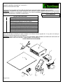
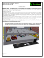
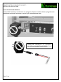
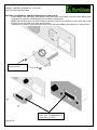
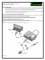
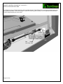
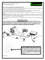
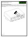
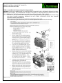
BurnGreen REMOTE CONTROL UPGRADE KIT - DXV-35 DEEP TIMBER III INSTALLATION & OPERATING INSTRUCTIONS NO. 8503008160510 WARNING If you do not follow these instructions exactly, a fire or explosion may result causing property damage, personal injury or loss of life. AVERTISSEMENT. Quiconque ne respecte pas à la lettre les instructions dans la présente notice risque de déclencher un incendie ou une explosion entraînant des dommages, des blessures ou la mort. CAUTION: Keep gasoline and other liquids having flammable vapors away. ATTENTION. Garder l’essence ou autres liquides produisant des vapeurs inflammables loin del’appareil. WHAT TO DO IF YOU SMELL GAS • Do not try to light any appliance. • Do not touch any electrical switch; do not use any phone in your building. • Immediately call your gas supplier from a neighbor's phone. Follow the gas supplier’s instructions. • If you cannot reach your gas supplier, call the fire department. QUE FAIRE SI VOUS SENTEZ UNE ODEUR DE GAZ : • Ne pas tenter d’allumer d’appareil. • Ne touchez à aucun interrupteur; ne pas vous servir des téléphones se trouvant dans le bâtiment. • Appelez immédiatement votre fournisseur de gaz depuis un voisin. Suivez les instructions du fournisseur. • Si vous ne pouvez rejoindre le fournisseur, appelez le service des incendies. WARNING Do NOT use this appliance if any part has been under water. Immediately call a qualified service technician to inspect the appliance and to replace any part of the control system and any gas control, which has been N’utilisez pas cet appareil s’il a été plongé dans l’eau, même partiellement. Faites inspecter l’appareil par un technicien qualifiéet remplacez toute partie du système de contrôle et toute commande qui ont été plongés dans l’eau. WARNING: Improper installation, adjustment, alteration, service or maintenance can cause injury or property damage. Refer to this manual. For assistance or additional information consult a qualified installer, service agency or the gas supplier. AVERTISSEMENT : Une installation, un réglage, une modification, une réparation ou un entretien mal effectué peut causer des dommages matériels ou des blessures. Voir la notice de l'utilisateur quiaccompgne l’appareil. Pour de l’aide oueds renseignements supplémentaires consultez un installateur un FOR YOUR SAFETY READ BEFORE LIGHTING POUR PLUS DE SÉCURITÉ, LIRE AVANTD'ALLUMER WARNING Do not operate this appliance with the glass removed, cracked or broken. A licensed or qualified person should do replacement of glass. Attention. Ne pas utiliser l’appareil si le panneau frontal en verre n’est pas enplace, est craqué ou brisé. Confiez leremplacement du panneau à untechnicien agréé. This appliance must be installed in accordance with local codes, if any; if none, follow the National Fuel Gas Code, ANSI Z223.1, or Canadian Installation Codes, CAN/CGA-B149. Gas and Propane Installation Code, CSA B149.1 Installer l'appareil selon les codes ou règlements locaux, ou, en l'absence dételés règlements, selon les codes d'installation ANSI Z223.1, National Fuel Gas Code ou CAN/CGA-B149 en This appliance is only for use with the type(s) of gas indicated on the rating plate and may be installed in an aftermarket, permanently located, manufactured home (USA only) or mobile home, where not prohibited by local codes. See owner's manual for details. This appliance is supplied with a conversion kit. Cet appareil doit être utilisé uniquement avec le type de gaz indiqué sur la plaque signalétique. Cet appareil peut être installé dans une maison préfabriquée ou mobile (É.-U. seulement) installée à demeure si les règlements locaux le permettent. Voir la notice de l'utilisateur pour plus de renseignements. Cet appareil ne peut pas être utilisé avecd'autres gaz sauf si une trousse deconversion certifiée est fournie. In the Commonwealth of Massachusetts: • Installation must be performed by a licensed plumber or gas fitter; • A CO detector shall be installed in the room where the appliance is installed. Caution: Label all wires prior to disconnection when servicing controls. Wiring errors can cause improper and dangerous operation. CAUTION: THESE INSTRUCTIONS ARE TO REMAIN WITH THE HOMEOWNER. Attention. Au moment de l’entretiennes commandes, étiquetez tous les fil savant de les débrancher. Des erreurs decâblage peuvent entraîner unfonctionnement inadéquat etdangereux. REMOTE CONTROL UPGRAGE KIT -DXV35 DT3 INSTALLATION INSTRUCTIONS REMOTE CONTROL UPGRADE KIT FEATURES - QUICK REFERENCE INFORMATION PILOT IGNITION CONTROL: IPI Electronic Ignition of Pilot Flame and main burners from Remote Control. Rear burner On/Off: Rear Burner On/OFF function from Remote Control. Flame Height Control: Flame height and heat output can be regulated from Remote Control. Blower On/Off and Speed Control: Remote Control can initiate blower On when fireplace is cold. Once unit warms up, Remote Control can regulate blower speeds in six steps. However, if Fireplace has warmed up, blowers will stay ON regardless of the remote control sending an OFF signal to Fireplace. In these instances, blowers will run at the preset LOW speed to extract all heat from fireplace. Blowers will turn OFF when unit cools down sufficiently. NOTE: RHEOSTAT MOUNTED IN COURTESY PANEL TO CONTROL BLOWER SPEED MUST BE ADJUSTED TO THE LOWEST BLOWER SPEED LEVEL IF THIS REMOTE CONTROL KIT IS INSTALLED. Accent Light On/OFF Control: Accent Light can be turned ON or OFF from remote control. Accent Light Dimming cannot be done from Remote Control. An additional Accent Light Dimmer mounted in Fireplace’s Courtesy Panel must be ON for accent light to function. Accent Light Dimmer mounted in Fireplace control Accent Light Intensity. Page 3 of 32 REMOTE CONTROL UPGRAGE KIT -DXV35 DT3 INSTALLATION INSTRUCTIONS Table of Contents FOR YOUR SAFETY READ BEFORE LIGHTING ................................................................................................................. 2 REMOTE CONTROL UPGRADE KIT FEATURES - QUICK REFERENCE INFORMATION............................................ 3 PARTS IDENTIFICATION DIAGRAM ..................................................................................................................................... 5 GENERAL INFORMATION ................................................................................................................................................ 6 BEFORE YOU BEGIN ........................................................................................................................................................ 6 AC/DC TRANSFORMER REMOVAL ................................................................................................................................. 7 BATTERY PACK REMOVAL AND RECEIVER INSTALLATION (item #2)........................................................................ 8 WIRING CONNECTIONS ....................................................................................................................................................... 9 STEP 1: ACCENT LIGHT SYSTEM PLUG HARNESS REMOVAL ................................................................................... 9 STEP 2: FAN CONTROL MODULE INSTALLATION (item #1) ......................................................................................... 9 STEP 3: FAN SYSTEM SECONDARY WIRING INSTALLATION ................................................................................... 11 STEP 4: TURN ON FAN CONTROL MODULE ................................................................................................................ 12 STEP 5: Install Motorized Pressure Regulator (Stepper Motor) ....................................................................................... 13 STEP 6: INSTALLING THE “WIRE HARNESS – RECEIVER CONNECTION” (item #7) .................................................... 14 WIRE HARNESS – RECEIVER CONNECTION (ITEM #7) IDENTIFICATION DIAGRAM ............................................. 15 i. CONNECTION TO REMOTE CONTROL RECEIVER .................................................................................................. 16 ii. CONNECTION TO THE FAN CONTROL MODULE (FCM) ......................................................................................... 16 iii. CONNECTION TO THE MOTORIZED PRESSURE REGULATOR (STEPPER MOTOR) ......................................... 17 iv. Connection to the Rear Burner Solenoid Valve (Split Flow) ....................................................................................... 17 v. Connection to the DC-Supply connector ...................................................................................................................... 18 vi. Connection to the Green colored TPTH terminal and the White Colored TH terminal (TPTH and TH) ...................... 18 TESTING THE MAIN WIRING SYSTEM .......................................................................................................................... 19 BEFORE YOU BEGIN .......................................................................................................................................................... 20 Remote Control Transmitter Functions ............................................................................................................................. 20 REMOTE TRANSMITTER OPERATING INSTRUCTIONS .................................................................................................. 21 TO TURN ON THE APPLIANCE: ..................................................................................................................................... 21 TO TURN OFF THE APPLIANCE. ................................................................................................................................... 21 MANUAL BYPASS OF THE REMOTE SYSTEM ................................................................................................................. 21 TEMPERATURE INDICATOR (oF or oC) .............................................................................................................................. 22 KEY LOCK FUNCTION......................................................................................................................................................... 22 LOW BATTERY POWER DETECTION ................................................................................................................................ 22 OPERATING DURING POWER OUTAGES ........................................................................................................................ 23 “FIRST TIME” LIGHTING INSTRUCTIONS .......................................................................................................................... 23 OPERATING DURING POWER OUTAGES .................................................................................................................... 23 NATURAL TO LP GAS CONVERSION INSTRUCTIONS .................................................................................................... 24 ORIFICE SIZES REQUIREMENT: ................................................................................................................................... 24 RECOMMENDED PROCEDURE TO CONVERT THIS FIREPLACE TO BURN LPG .................................................... 24 INSTALLING THE LP PRESSURE REGULATOR ........................................................................................................... 27 INSTALLING THE LP PRESSURE REGULATOR ........................................................................................................... 27 LP GAS PRESSURE REQUIREMENTS .............................................................................................................................. 28 LPG PROPER INPUT RATES.......................................................................................................................................... 28 LEAK TESTING REQUIREMENTS .................................................................................................................................. 28 PILOT FLAME AND MAIN BURNER RELATIONSHIP VERIFICATION.......................................................................... 28 PILOT FLAME LENGTH ADJUSTMENT.......................................................................................................................... 28 CHECKING FOR NORMAL BURNER (S) IGNITION CHARACTERISTICS ................................................................... 29 ATTACHING LPG CONVERSION LABELS AND HIGH ALTITUDE DERATION LABEL................................................ 29 Page 4 of 32 REMOTE CONTROL UPGRAGE KIT -DXV35 DT3 INSTALLATION INSTRUCTIONS This instructions set applies to both the NG and LPG Remote Upgrade Kits [#AA-11-01256 & AA-11-01257]. WARNING: THIS REMOTE KIT IS NOT DESIGNED FOR USE WITH OLDER GENERATION DXV35 UNITS. DO NOT ATTEMPT TO INSTALL THIS REMOTE CONTROL KIT ON YOUR SHOWROOM DISPLAY UNIT IF IT IS OF AN OLDER GENERATION DXV35TF, DXV35DT1 OR DXV35DT2. TOOLS REQUIRED ¼” HEX DRIVER & SCREW GUN LIST OF PARTS INCLUDED KEY 1 2 3 4 5 6 7 8 9 QTY. DESCRIPTION 1 FAN CONTROL MODULE W/ HEAT SHIELD 1 REMOTE RECEIVER W/ 4X “AA” BATTERIES 1 REMOTE TRANSMITTER 3 “AAA” BATTERIES (for Transmitter) 4 MOTORIZED PRESSURE REGULATOR (LPG OR NG) 1 TORX WRENCH (for Pressure Regulator Installation) 1 WIRE HARNESS – RECEIVER CONNECTION 1 PLUG WIRE HARNESS – Blower System 1 THIS INSTRUCTIONS MANUAL Open this package and identify the parts included in this Remote Control Upgrade Kit. If any parts are missing or damaged, contact the Mendota Service Department. WARNING: THIS KIT MUST BE INSTALLED BY AN AUTHORIZED AND TRAINED GAS FIREPLACE INSTALLER OR SERVICE PERSON. INSTALLATION BY A “HOME OWNER” IS PROHIBITED! PARTS IDENTIFICATION DIAGRAM 1 8 2 9 7 6 Page 5 of 32 5 3 4 REMOTE CONTROL UPGRAGE KIT -DXV35 DT3 INSTALLATION INSTRUCTIONS INTRODUCTION WARNING: THIS KIT MUST BE INSTALLED BY AN AUTHORIZED AND TRAINED GAS FIREPLACE INSTALLER OR SERVICE PERSON. INSTALLATION BY A “HOME OWNER” IS PROHIBITED! THIS KIT IS DESIGNED FOR INSTALLATION ON DXV35 DT3 MODEL UNITS ONLY. THIS KIT IS NOT COMPATIBLE WITH OLDER GENERATION DXV35, DXV35TF, DXV35DT1 OR DXV35DT2 MODELS. GENERAL INFORMATION This MENDOTA BurnGreen Remote Control upgrade kit adds remote control functionality to all features of the DXV35 DT3 Fireplace. This includes Manual, Thermostatic and Smart Thermostat functions, IPI pilot flame ignition and main burner ignition functions, Flame Height modulation function, Rear Burner On/Off function, Accent Light On/Off function and Blower speed regulation function. NOTE: This Remote Kit Will Not Turn The Blower System To Off If The Fireplace Is Hot. The Blower Will Turn Off Only If The Fireplace Has Cooled Down Close To Room Temperature. This is a feature installed to transfer ALL heat contained in the Fireplace Body to the living space rather than letting the heat expel out through the exhaust system. BEFORE YOU BEGIN CAUTION: MAKE CERTAIN THE PILOT LIGHT IS TURNED OFF AND DISCONNECT THE ELECTRICITY SUPPLY TO THIS FIREPLACE BEFORE STARTING THIS UPGRADE PROCESS. Open glass door and remove glass frame and set aside. Remove two screws that secure courtesy panel to Valve Assembly then slowly pull Courtesy Panel our of Unit and rotate down to expose rear surface of Courtesy Panel. DO NOT PUT TENSION ON WIRE HARNESSES! Page 6 of 32 REMOTE CONTROL UPGRAGE KIT -DXV35 DT3 INSTALLATION INSTRUCTIONS AC/DC TRANSFORMER REMOVAL Locate AC/DC Transformer on left side of unit. If plugged in Fireplace’s Left Side Outlet, unplug and remove transformer and discard Transformer or save it in your replacement parts stock. REMOVE TRANSFORMER; DISCONNECT TRANSMITTER CONNECTOR AT “DC-SUPPLY” CONNECTION. DISCARD TRANSFORMER OR SAVE IT IN YOUR REPLACEMENT PARTS STOCK.. Page 7 of 32 REMOTE CONTROL UPGRAGE KIT -DXV35 DT3 INSTALLATION INSTRUCTIONS BATTERY PACK REMOVAL AND RECEIVER INSTALLATION (item #2) Locate Battery Pack and Battery Pack Bracket. Disconnect Wires from Battery Pack and remove Battery Pack and Battery Pack Bracket. Discard Battery Pack and Battery Pack Bracket. NOTE: Red and Black Wires connected to Battery will not be used with the Remote Kit. Leave wires intact inside fireplace but not connected to any other wire harnesses. Install Receiver. Receiver mounts using the same screws that secured Battery Pack Bracket to Courtesy Panel. Reuse these screws to mount Receiver. NOTE: Battery Compartment cover with “ON-REMOTE-OFF” decal shall be on TOP. Page 8 of 32 REMOTE CONTROL UPGRAGE KIT -DXV35 DT3 INSTALLATION INSTRUCTIONS WIRING CONNECTIONS Follow all wiring instructions in the exact order given here. Failure to follow in order will lead to improper wiring which can lead to damage to the gas valve, rear burner solenoid, fan control module, fan rheostat and remote receiver. Damage due to improper wiring is not covered under the Mendota Warranty Policy. Follow each step, below, exactly and in the exact order given. Make certain that the Courtesy Panel is removed and rotated downward to provide access inside the fireplace cavity. STEP 1: ACCENT LIGHT SYSTEM PLUG HARNESS REMOVAL Locate Accent Light Harness Plug. Trace the wires from the Accent Light Dimmer to the Plug. This plug is factory assembled and plugged in to the “FRONT” outlet on the Right Side of the Fireplace. Unplug the Accent Light Harness from where it is plugged in and pull out towards the front of the unit. WARNING: DO NOT REMOVE THE OTHER PLUG THAT IS CONNECTED TO THE REAR OUTLET! STEP 2: FAN CONTROL MODULE INSTALLATION (item #1) Unwrap and extend the plug harness connected to the Fan Control Module (FCM). Insert FCM plug inside unit on right side and plug this harness into the same outlet you removed the Accent Light Plug from. Plug the Accent Light Plug into the AUX OUT outlet on the Fan Control Module. REAR OUTLET FCM FRONT OUTLET AUX ACCENT LIGHT PLUG LIGHT DIMMER Page 9 of 32 TO ACCENT LIGHT REMOTE CONTROL UPGRAGE KIT -DXV35 DT3 INSTALLATION INSTRUCTIONS The FCM sits on the right side against the silver insulation foil wall. Push FCM as far to the right as possible and pull as far forward as possible. This is a very tight fit. Route the FCM Plug cable carefully. You must provide room above the FCM for the gas supply line to be routed. Gas Supply Line Runs over Page 10 of 32 REMOTE CONTROL UPGRAGE KIT -DXV35 DT3 INSTALLATION INSTRUCTIONS STEP 3: FAN SYSTEM SECONDARY WIRING INSTALLATION Look into the unit cavity behind the gas valve. Locate a loose cable bundle with a label that reads “FCM FAN PLUG ONLY”. This cable bundle has three wires: White, Black and Green. Remove the Male connectors that are plugged on the ends of all three wires and discard the loose Male connectors. Locate item #8 of the shipment you received “PLUG WIRE HARNESS – blower system”. Connect the color matched ends of the PLUG WIRE HARNES to the ends of the “FCM FAN PLUG ONLY” labeled wire bundle. WARNING: CONNECT WHITE TO WHITE, BLACK TO BLACK AND GREEN TO GREEN ONLY! IF YOU DO NOT MATCH WIRE COLORS IN THIS STEP, YOU WILL CREATE A SHORT CIRCUIT THAT WILL DAMAGE THE FANS, THE FAN RHEOSTAT, THE FCM AND OTHER COMPONENTS. Once the connections are made, insert the PLUG WIRE HARNESS into the receptacle in the Fan Control Module (FCM) labeled ‘FAN”. IMPORTANT NOTE RHEOSTAT MOUNTED IN COURTESY PANEL TO CONTROL BLOWER SPEED MUST BE ADJUSTED TO THE LOWEST BLOWER SPEED LEVELWHEN THIS REMOTE CONTROL KIT IS INSTALLED. IF YOU DO NOT ADJUST THE RHEOSTAT SPEED TO ITS LOWEST SETTING AND THE RHEOSTAT IS SET AT A HIGHER SPEED, THE REMOTE CONTROL WILL ONLY REGULATE THE BLOWER SPEED DOWN TO THE SPEED LEVEL THAT THE RHEOSTAT IS SET AT. TURN THE RHEOSTAT KNOB TO ITS LOWEST SPEED POSITION! R IG H T S ID E O U T LE T S B LU E T-TA P S RH BLOW ER GROUND FAN CONTROL M O D U LE GREEN W HI TE K E AC W H IT HW HW HW HW HW HW HW BL AC BL LH BLOW ER FCM FA P LU G N ONLY BL AC K FC HA M FA RN N E S PLU S G GREEN AC PL CE UG N T H A L IG RN H ES T S TO ACCENT L IG H T H O U S IN G K S N A P D IS K L IG H T D IM M E R BLOW ER RHEOSTAT RHEOSTAT KNOB MUST BE TURNED TO “LOW”. ONCE THE REMOTE CONTROL KIT IS INSTALLED, THIS KNOB HAS NO FUNCTION EXCEPT TO SET THE LOWEST BLOWER SPEED. IF YOU DO NOT SET IT TO LOW, THE REMOTE SYSTEM WILL NOT BE ABLE TO MODULATE THE BLOWER SPEED BELOW THE SPEED THAT IS SET WTH THIS RHEOSTAT. Page 11 of 32 REMOTE CONTROL UPGRAGE KIT -DXV35 DT3 INSTALLATION INSTRUCTIONS STEP 4: TURN ON FAN CONTROL MODULE The fan control module has a power switch. Make sure it is in the ON (“-“) position. This switch must remain in the ON position for the AC components to operate (Accent Light and Blower). This module also supplies low-voltage power for the fireplace controller. By leaving it in the OFF position, the fireplace will operate off the receiver batteries, greatly diminishing battery life. Page 12 of 32 REMOTE CONTROL UPGRAGE KIT -DXV35 DT3 INSTALLATION INSTRUCTIONS STEP 5: Install Motorized Pressure Regulator (Stepper Motor) WARNING: READ AND UNDERSTAND ALL INSTRUCTIONS PACKAGED WITH PRESSURE REGULATOR BODY BEFORE YOU ATTEMPT THE CONVERSION. FAILURE TO FOLLOW ALL INSTRUCTIONS WILL RESULT IN A LEAK OR OVERFIRING OF THE APPLIANCE AND CAN LEAD TO AN EXPLOSION OR A FIRE HAZARD. Remove the Courtesy Access Panel mounted behind the lower grill and lay down gently without disconnecting any wires of internal components. WARNING: DO NOT FORCE. EXCESSIVE FORCE MAY DAMAGE INTERNAL WIRING COMPONENTS! Pull out and remove Extension Knob on NG Pressure Regulator and set aside. Follow Instructions given below directly from SIT Controls. Replace Extension Knob as the final step. Page 13 of 32 REMOTE CONTROL UPGRAGE KIT -DXV35 DT3 INSTALLATION INSTRUCTIONS STEP 6: INSTALLING THE “WIRE HARNESS – RECEIVER CONNECTION” (item #7) A total of 6 different connections must be made for the entire system to operate properly. i. Connection to the Remote Control Receiver (RECEIVER) ii. Connection to the Fan Control Module (FCM-COM) iii. Connection to the Motorized Pressure Regulator (MOTOR) iv. Connection to the Rear Burner Solenoid Valve (SPLITFLOW) v. Connection to the DC-Supply connector (DFC-SUPPLY) vi. Connection to the Green colored TH terminal and the White Colored TPTH terminal (TPTH and TH) Follow the instructions in the order given. Although there are SIX connections to be made, all six connections are unique in shape and color and cannot be mistaken. Below, is a general wiring diagram that will help you identify the first four connections. Connections 5 & 6 are now shown here. Detailed diagrams are provided in the specific sections in this manual that cover the #5 & #6 connections. Page 14 of 32 REMOTE CONTROL UPGRAGE KIT -DXV35 DT3 INSTALLATION INSTRUCTIONS WIRE HARNESS – RECEIVER CONNECTION (ITEM #7) IDENTIFICATION DIAGRAM The diagram, below, depicts the “Wire Harness – Receiver Connection”. Each end is numbered according to the installation instructions steps and the identifying labels attached to each end. ii. FCM-COM iii. MOTOR iv. SPLITFLOW i. RECEIVER vi. TPTH & TH V. DFC-SUPPLY ii. FCM-COM i. RECEIVER Page 15 of 32 REMOTE CONTROL UPGRAGE KIT -DXV35 DT3 INSTALLATION INSTRUCTIONS i. CONNECTION TO REMOTE CONTROL RECEIVER Connect the white multi-wire connector labeled “RECEIVER” to the port in the rear of the Remote Receiver. Note that the connectors are keyed so insertion is only allowed if the connectors are oriented correctly. Do not force. If connectors are aligned properly, they will engage easily. See diagram, below. RECEIVER ii. CONNECTION TO THE FAN CONTROL MODULE (FCM) Locate the COM port in the FCM. Locate the small white connector labeled “FCM-COM”. Note that the connectors are keyed so insertion is only allowed if the connectors are oriented correctly. Do not force. If connectors are aligned properly, they will engage easily. FCM-COM Page 16 of 32 REMOTE CONTROL UPGRAGE KIT -DXV35 DT3 INSTALLATION INSTRUCTIONS iii. CONNECTION TO THE MOTORIZED PRESSURE REGULATOR (STEPPER MOTOR) Locate the ribbon cable connected to the Motorized Pressure Regulator. The connector at the end of this cable connects to the connector labeled “MOTOR” that is part of the Receiver Harness. The connectors can mate only one way. Do not force. STEPPER MOTOR CONNECTORS iv. Connection to the Rear Burner Solenoid Valve (Split Flow) Locate the loose connector at the end of the Pink and Blue wires that are attached to the Rear Burner Solenoid Valve (Split Flow). Locate the connector labeled “SPLIT FLOW” in the Receiver Harness. Attach these two connectors together. Make certain pins in the male connector are not bent before connecting to the female connector. SPLITFLOW Page 17 of 32 (SPLIT FLOW) REAR BURNER SOLENOID CONNECTORS REMOTE CONTROL UPGRAGE KIT -DXV35 DT3 INSTALLATION INSTRUCTIONS v. Connection to the DC-Supply connector See diagram, below, that identifies the connectors on the left side of the Courtesy panel’s back-side.. Identify the “DC- SUPPLY” CONNECTOR from which you disconnected the AC/DC Transformer. Identify the matching connector that is part of the “Receiver Harness”. Connect the Male AC/DC adapter to the connector labeled “DC-SUPPLY”. DFC-SUPPLY vi. Connection to the Green colored TH terminal and the White Colored TPTH terminal (TPTH and TH) Locate the ON/OFF Switch on the left side of Courtesy Panel. Identify the short jumper wires that are connected to the switch. Identify the Green and White colored wires with label “ON-OFF” that connect to these two short jumper wires. Disconnect the White and Green wires connected to the short jumper wires. Identify the Green Wire (part of the Receiver Harness) labeled “TH”. Connect this wire to the Green wire labeled “ON-OFF”. Identify the White Wire (part of the Receiver Harness) labeled “TPTH”. Connect this wire to the White wire labeled “ON-OFF”. ON-OFF 1. 2. 3. TPTH TH WARNING – GREEN WIRE (TH) MUST MATE WITH GREEN WIRE IN ON-OFF CIRCUIT. WHITE WIRE (TPTH) MUST MATE WITHWHITE WIRE IN ON-OFF CIRCUIT. IF YOU MISMATCH COLORS, YOUR SYSTEM WILL NOT FUNCTION! Page 18 of 32 DISCONNECT “ON-OFF” WIRES FROM ON/OFF SWITCH WIRE JUMPERS. CONNECT “TH” WIRE TO GREEN “ONOFF” WIRE CONNECT “TPTH” WIRE TO WHITE “ON-OFF” WIRE. REMOTE CONTROL UPGRAGE KIT -DXV35 DT3 INSTALLATION INSTRUCTIONS Connections of all new wire connector ends are now complete. Double check all connections and confirm that all connections are secure and that wires are routed properly so no wires will be pinched when replacing the Courtesy Panel. DO NOT REPLACE THE GLASS FRAME AT THIS TIME. TESTING THE MAIN WIRING SYSTEM 1. Turn ON the electricity to Fireplace. 2. Turn ON the gas supply to Fireplace. 3. Toggle PILOT LIGHT ON/OFF SWITCH to “Standing Pilot” position. You should hear and visibly see sparking at the pilot light. After the air in the gas line has bled through, the pilot light will ignite and remain lit. 4. Slide Remote Receiver Slider Switch to ON. Burners should ignite. Slide Remote Receiver Slider Switch to “REMOTE” position once burners ignite. DO NOT LEAVE BURNERS ON FOR MORE THAN 30 SECONDS. 5. Install Glass Frame on Fireplace and secure with two spring latched located on top of firebox. 6. Insert “AAA” Batteries in Remote Transmitter. 7. Press “PRG” button on Remote Receiver. You will hear a “beep”. 8. Press any button on the Remote Transmitter. You will hear “beep, beep, beep” indicating that the remote transmitter and remote receiver are synchronized. 9. Test Blower Functions and Accent Light Functions in “MANUAL THERMOSTAT MODE”. See REMOTE TRANSMITTER OPERATING INSTRUCTIONS section of this manual. Once you have verified that all functions operate properly, reinstall Courtesy Panel carefully. Make certain no wires or connectors are pinched between metal parts. Page 19 of 32 REMOTE CONTROL UPGRAGE KIT -DXV35 DT3 INSTALLATION INSTRUCTIONS BEFORE YOU BEGIN Read this entire manual before you use your new fireplace (especially the section “Safety Precautions” on page 2). Failure to follow the instructions may result in property damage, bodily injury, or even death. Remote Control Transmitter Functions NOTE: The Wall Receiver will “beep” once every time a Remote Transmitter Key is pressed, signaling that the command has been received. Identify the four function buttons on the Remote Transmitter: 1. ON/OFF KEY: This button turns the system ON or OFF. When this button is pressed and the system is OFF, the pilot light will stay ON if the “Standing Pilot Switch” is in the ON position. 2. THERMOSTAT KEY: This button, when pressed after the ON/OFF KEY is pressed and the system is ON, will allow the selection of three modes: Manual Operation, Normal Thermostat and Smart Thermostat. a. Manual Mode: In this mode, the room temperature is ignored and the fireplace can be turned ON indefinitely. The room temperature rise has no effect on this mode. All other functions such as flame height control, secondary burner On/OFF control and Accent Light ON/OFF controls will be manually controllable. Fan speed will be manually controllable always but if unit is SMART ON OFF hot, fan cannot be turned to OFF. b. Normal Thermostat: In this mode, the fireplace will stay functioning until the room temperature increases 1oF above the Set Point Temperature. To increase the Set Point Temperature, Press the UP button until the desired temperature is displayed in the SET POINT TEMPERATURE window. The fan will turn on 5 minutes after fireplace startup or when fireplace warms up and will turn off 12-1/2 minutes after the flames turn off or when unit cools down, in this mode. The flame height can be adjusted while the fireplace is functioning, fan speed can be adjusted after 5 minutes of startup. Secondary burner can be turned On or Off at any time after startup. The Accent Light can be turned on or off any time after startup. OFF 76°F ON Hi MAX MANUAL MODE c. 76°F SMART 76°F Hi 68 NORMAL THERMOSTAT SMART MODE MAX Smart Thermostat: In this mode, all other functions except the flame height adjustment are allowed. Manual flame height adjustment is not allowed in this mode. The Smart Thermostat function adjusts the flame height in accordance to the difference between the set point temperature and the actual room temperature. As the room temperature gets closer to the set point temperature, the Smart Function automatically modulates the flame down. UP/DOWN KEY: This key is used to increase or decrease the Set Point Temperatures, Flame Height and Fan Speed and to toggle between Accent Light ON/OFF and Secondary Burner ON/OFF. MODE SELECTION KEY: This key is used to toggle between the various function icons: Flame Height, Fan Speed, Accent Light and Secondary Burner. Page 20 of 32 REMOTE CONTROL UPGRAGE KIT -DXV35 DT3 INSTALLATION INSTRUCTIONS REMOTE TRANSMITTER OPERATING INSTRUCTIONS TO TURN ON THE APPLIANCE: 1. Press the ON/OFF button. The transmitter display will show all active icons on the screen. 2. Select the Thermostat Mode by pressing the Thermostat Key: OFF (meaning Manual Mode), ON (meaning normal Thermostat) or Smart (meaning Smart Mode). a. In OFF (Manual Mode), the appliance will ignite and start on HI. b. In ON (Normal Thermostat Mode), the appliance will only ignite if the Set Temperature is greater than the Room Temperature. c. In SMART (Smart Mode), the appliance will only ignite if the Set Temperature is greater than the Room Temperature. TO TURN OFF THE APPLIANCE, press the ON/OFF button. MODE KEY Pressing the MODE KEY toggles between the various available functions: Flame Height, Fan Speed, Aux (Accent Light) On/Off and Secondary Burner On/Off. Flame Height: 6 flame height Levels are available. While the Flame Height Icon is displayed, pressing the Up or Down button once will increase or decrease the flame height by 1 of 6 increments. If the flame height is at Level 1 and the Down button is pressed, all burners will turn OFF. If in IPI mode, the pilot light will also extinguish. If in Standing Pilot Mode, the pilot light will remain ON. Note: If in SMART model, the flame height function is not available for manual adjustment. In SMART mode, the flame height regulates automatically. Fan Speed Control: The fan speed can be adjusted through six (6) speeds and OFF. To activate this function, press the MODE Key to index to the fan control icon. Use the UP/Down Arrow Key to turn ON, OFF or adjust the fan speed. A single “beep” will confirm reception of the command. The Fan will continue to run if the unit is warm until unit cools down. Aux (Accent-Light): This function controls the Mendota Accent Light function. Pressing the UP key in this mode will TURN ON the Accent Light and Pressing the DOWN key will TURN OFF the Accent Light. A single “beep” will confirm reception of the command. Note: The Accent Light Dimmer control is located adjacent to the Remote Receiver. Turn the Dimmer Control Knob to dim or brighten the Accent Light. Once you set your desired brightness level, you may use the AUX function to turn the Accent Light On or Off at that preset level. Secondary Burner: This function controls the Secondary Burner’s ON/OFF feature. Pressing the UP Key in this mode will TURN ON the Secondary Burner and Pressing the DOWN Key will TURN OFF the Secondary Burner. The flame level will not change when you turn the Secondary Burner On or Off. The flame level can only be changed in the Flame Level mode. MANUAL BYPASS OF THE REMOTE SYSTEM If the remote transmitter is misplaced or lost, the appliance can be turned on manually by sliding the three position slider switch on the wall receiver to the ON position. This will bypass the remote Page 21 of 32 REMOTE CONTROL UPGRAGE KIT -DXV35 DT3 INSTALLATION INSTRUCTIONS control feature of the system and the appliance’s main burner will turn on. The fan will run at its maximum speed and the Accent Light may turn on. To turn off the appliance, if the remote control is misplaced or lost, slide the three position slider switch on the wall receiver to the OFF Position. TEMPERATURE INDICATOR (oF or oC) 1. Press the ON/OFF Key and Turn Off the Fireplace. 2. Simultaneously, Press both the MODE Key and the Thermostat Key. 3. Look at the LCD display to verify that your desired indicator (oF or o C) is being displayed. If not, repeat step 2. KEY LOCK FUNCTION To prevent unsupervised children from operating the fireplace, a KEY LOCK function is provided with this remote control system. To activate the KEY LOCK function, simultaneously press the “MODE KEY” and the “UP KEY”. To deactivate the KEY LOCK function, simultaneously press the “MODE KEY” and the “UP KEY”. During KEY LOCK mode, none of the Keys will function. You must DEACTIVATE the system before you can use the Remote Transmitter. LOW BATTERY POWER DETECTION 1. Transmitter Batteries: The life span of the remote control transmitter batteries depends on various factors: quality of the batteries used, the number of ignitions of the appliance, the number of changes to the room thermostat set point, etc. When the Transmitter batteries are low, a Battery Icon will appear on the LCD display of the Transmitter before all battery power is lost. When the batteries are replaced, this icon will disappear. 2. Receiver Batteries: The life span of the receiver batteries depend on the quality of the batteries used and how long the batteries have been installed in the receiver. These batteries are only utilized during power outages. Replace these batteries every heating season even if you have not experienced any power outages. Batteries drain slowly even when not in use. This is a normal characteristic of all batteries. Page 22 of 32 REMOTE CONTROL UPGRAGE KIT -DXV35 DT3 INSTALLATION INSTRUCTIONS OPERATING DURING POWER OUTAGES This electronic ignition system utilizes the supplied 110VAC power when it is available for all functions of this system. If the AC power is interrupted during a power outage, this system utilizes the batteries (installed in the Wall Receiver) as back-up batteries. During the power outage, the appliance’s burners will function. In addition, Flame Height adjustment and Secondary Burner ON/OFF functions will be available. The Fan and Accent Light, which are wholly dependent on 110VAC power, will not function. This appliance is designed and tested to be operated during power outages. The overall efficiency of this appliance will be reduced by approximately 5% when the blower function is disabled during the power outage period. “FIRST TIME” LIGHTING INSTRUCTIONS IMPORTANT: Be sure all items on "INSTALLATION CHECK OFF LIST" in the Installation Manual have been completed! CAUTION: If the pilot goes out, be sure to wait a minimum of five minutes before attempting to relight the pilot. Make certain that any manual gas supply shut-off valves located upstream of fireplace are open. Make certain that 120VAC power is connected [and ON] to the electrical junction box on the left side of unit. Insert Batteries in the Battery Holder if not already installed at the factory. Note the polarity of batteries and insert as indicated on the battery compartment covers. For the “First Time Lighting”, Remove the Glass Door. This is required to purge the gas line of air and to inspect the pilot lighting spark. Locate the “Standing Pilot ON/OFF Switch”. Toggle “Standing Pilot ON/OFF Switch” to “ON”. You will hear a series of clicks and after a few seconds, you will hear sparking at the pilot spark electrode. Visually inspect the spark at the pilot hood and verify that the spark jumps from the spark electrode to the pilot hood. Allow adequate time for the air in the gas-line to purge. The control system will stop sparking after 30 seconds if the pilot light does not light. After a 30 second delay the control system will start sparking again for 30 seconds more. If the pilot light does not light after the third 30 second spark event, the system will enter “Lock-out” mode. To unlock from “Lock-out” mode, toggle “Standing Pilot ON/OFF Switch to “OFF” and toggle Main ON/OFF Switch to “ON”, wait 30 seconds and toggle Main ON/OFF Switch to OFF. Toggle “Standing Pilot ON/OFF Switch to ON. Repeat this sequence until the pilot flame lights and the pilot is burning steadily. LOCK OUT MODE: If the pilot light does not light after the third 30 second spark event, the system will enter “Lockout” mode. To unlock from “Lock-out” mode, toggle “Standing Pilot ON/OFF Switch to “OFF” and toggle Main ON/OFF Switch to “ON” (the sparking will start again); wait 30 seconds and toggle Main ON/OFF Switch to OFF. This will reset the system. Once the pilot flame is lit and well-established, close glass door. WARNING: NEVER IGNITE MAIN BURNERS WITH GLASS DOOR REMOVED OR OPEN. Doing so will lead to damage to pilot flame sensor wire and spark electrode wire leads. Toggle Main Burners ON/OFF Switch to “ON”. All burners should ignite and run at “high-fire”. If rear burner does not turn ON, toggle Rear Burner ON/OFF Switch to ON. After 15 seconds, Toggle Main Burners ON/OFF Switch to OFF. Burner Flames will extinguish. Perform gas inlet and outlet pressure tests and leak tests on field installed gas fittings and factory installed fittings in the gas valve compartment, at this time. Note: Burners must be ON to check outlet pressures and to leak test gas train fittings upstream of main gas valve. Backup Batteries: The life span of the backup batteries depends on the quality of the batteries used and how long the batteries have been installed in the wall receiver. These batteries are utilized during power outages. Replace these batteries every heating season. Batteries drain slowly even when not in use. This is a normal characteristic of all batteries. OPERATING DURING POWER OUTAGES This electronic ignition system utilizes the supplied 110VAC power when it is available for all functions of this system. If the AC power is interrupted during a power outage, this system utilizes the batteries (installed in the Wall Receiver) as back-up batteries. During the power outage, the appliance’s burners will function. In addition, Flame Height adjustment and Secondary Burner ON/OFF functions will be available. The Fan and Accent Light which are wholly dependent on 110VAC power, will not function. Page 23 of 32 REMOTE CONTROL UPGRAGE KIT -DXV35 DT3 INSTALLATION INSTRUCTIONS NATURAL TO LP GAS CONVERSION INSTRUCTIONS Kit # HA-30-00501 Mendota Model DXV35 DT3 4 36 Burner Orifice #65-14-00364 [3/64"DRILL] 4 36 This conversion kit shall be installed by a qualified service agency in accordance with the manufacturer’s instructions and all applicable codes and requirements of the authority having jurisdiction. If the information in these instructions is not followed exactly, a fire, explosion or production of carbon monoxide may result causing property damage, personal injury or loss of life. The qualified service agency is responsible for the proper installation of this kit. The installation is not proper and complete until the operation of the converted appliance is checked as specified in the owner instructions supplied with the kit. Caution: The electrical supply to the fireplace must be turned off prior to performing the conversion. The gas supply must be shut off prior to disconnecting the electrical power. MANUAL LP Pressure Regulator [10.0-6.4"WC] # 0.907.011 LP Pilot Orifice ORIFICE SIZES REQUIREMENT: [#05-04-00052] A Natural Gas to LPG conversion kit #HA-30-00501 is included [#977.168] with this fireplace insert. LP Conversion Kit # HA-30-00501 contains the following parts: One Motorized LP Pressure Regulator #907.012, One LP Pilot Orifice Thimble #977.168, and two Cap Orifices #65-14-00364(drill #3/64”) and an L-shaped Torx wrench. RECOMMENDED PROCEDURE TO CONVERT THIS FIREPLACE TO BURN LPG This Fireplace Insert arrives from the factory ready to burn Natural Gas. If you intend to burn LPG, it is highly recommended that you convert this fireplace and its Pressure Regulator, Pilot Orifice Thimble and Burner Orifices prior to placing this fireplace in its fireplace cavity. See diagrams, on this page, and follow these instructions to prepare this fireplace for conversion to LPG. Using a ¼” Hex Driver, remove 2 screws that secure the Rear and Front burners to the Burner Airbox. Lift Up and remove Front Burner. Loosen Front Burner Air Shutter Screw and rotate air shutter open ¼” minimum. Set burner aside. Slide Rear Burner to the right about 2” and lift up and remove from Firebox. REA R BURNER BURNERS M O UNTING SC REW S FRO NT BURNER Page 24 of 32 REMOTE CONTROL UPGRAGE KIT -DXV35 DT3 INSTALLATION INSTRUCTIONS 1. Using a ½” deep well socket wrench, remove Front and Rear Orifices. 2. Thread a new 3/64” drilled orifice to both Front and Rear Orifice mounting brass fittings. Tighten down orifices. 3. Install pilot orifice thimble ##977.168 see Figure below for location. To remove Pilot Hood, use a screw driver to pry open the Wire Clip that is located at the base of the Pilot Hood. Pull Upward and remove pilot hood. Use an Alan wrench to remove NG Pilot Orifice. (Pilot orifice thimble is located inside pilot hood base). 4. Install LP Pilot Orifice. Tighten down using an Alan wrench. Replace Wire Clip in its original position. 5. Push Pilot Hood down into base until it snaps in place. DETAIL C Pull Pilot Hood UP and lift UP off the base. REAR ORIFICE Use an Alan Wrench To loosen and remove NG Pilot Orifice. Install LP Pilot Orifice, Tighten Down. WIRE CLIP. FRONT ORIFICE DETAIL D REAR BURNER PILOT LIGHT HOOD FRONT BURNER Page 25 of 32 REMOTE CONTROL UPGRAGE KIT -DXV35 DT3 INSTALLATION INSTRUCTIONS Before reinstalling burners, loosen the screw that secures the rotary air shutter on the Front Burner. Rotate the air shutter open to ¼” minimum. Install both rear and front burners in their original locations and positions and secure down using screws you removed earlier. LO O SEN SC R EW R O TA TE SH U TTE R O P EN -1 / 4 " M IN IM U M - NOTE: The recommended air shutter setting are ¼” min For LPG and 1/8” min for NG. FR O N T B U R N E R SH U TTER A D JU STM EN T Make certain front burner is running parallel to front face of unit positioned properly so that the pilot light hood pointing to the left is pointed properly towards the burner’s flame propagation ports. Make certain Rear Burner is positioned properly so that the pilot light hood pointing to the left is pointed properly towards the burner’s flame propagation holes. REAR BURNER PILOT LIGHT FLAMES MUST OVERLAP BURNER PORTS. FRONT BURNER Page 26 of 32 REMOTE CONTROL UPGRAGE KIT -DXV35 DT3 INSTALLATION INSTRUCTIONS INSTALLING THE LP PRESSURE REGULATOR WARNING: READ AND UNDERSTAND ALL INSTRUCTIONS PACKAGED WITH LP PRESSURE REGULATOR BODY BEFORE YOU ATTEMPT THE CONVERSION. FAILURE TO FOLLOW ALL INSTRUCTIONS WILL RESULT IN A LEAK OR OVERFIRING OF THE APPLIANCE AND CAN LEAD TO AN EXPLOSION OR A FIRE HAZARD. Remove the Courtesy Access Panel mounted behind the lower grill and lay down gently without disconnecting any wires of internal components. WARNING: DO NOT FORCE. EXCESSIVE FORCE MAY DAMAGE INTERNAL WIRING COMPONENTS! Pull out and remove Extension Knob on NG Pressure Regulator and set aside. Follow Instructions given below directly from SIT Controls. Replace Extension Knob as the final step. Page 27 of 32 REMOTE CONTROL UPGRAGE KIT -DXV35 DT3 INSTALLATION INSTRUCTIONS LP GAS PRESSURE REQUIREMENTS Inlet and manifold gas pressure checking taps are located on gas valve. These ports are only accessible from the outer left side of the fireplace. A qualified installer shall take pressure measurements at these ports to verify and set the correct gas pressures during the LP Kit installation and before fascia materials are installed over the front of this fireplace. Manifold pressure must be taken at the “MANIFOLD PRESSURE" tap and inlet pressure at the "INLET PRESSURE" tap with the burner operating by a qualified installer. L.P. GAS DESIRED INLET PRESSURE 11.0" W.C. (2.75 kPa) MINIMUM INLET PRESSURE 11" W.C. (2.75 kPa) REGULATE THE FLAME HEIGHT TO "HIGH" POSITION. 5%. MAXIMUM INLET PRESSURE 13.0" W.C. (3.24 kPa) MANIFOLD OUTLET PRESSURE 10.0" W.C. (2.5 kPa) AIR SHUTTER POSITION 1/4" OPEN MIN. (5 mm) OUTLET GAS PRESSURES MAY VARY PLUS OR MINUS LPG PROPER INPUT RATES With the proper orifices installed, as specified above, this fireplace utilizing LP Gas will have a maximum input rate of 31,000 Btu/Hr. LEAK TESTING REQUIREMENTS Prior to completing the conversion process, check for gas leaks with soap and water solution at all plumbing joints prior to placing this appliance into operation. It is recommended that all gas-plumbing joints, factory installed and field installed are checked for leaks. INLET TAP OUTLET TAP PILOT FLAME AND MAIN BURNER RELATIONSHIP VERIFICATION Figure 1: Pressure Test Port Prior to completing the conversion process, the qualified service technician must, light the pilot light and verify the relationship between the pilot light flames and the main burners. The pilot light flames directed towards the propagation ports on the rear and front burner must overlap the propagation ports on the burners. The pilot light flames must be a minimum of ¾” long and must overlap the propagation ports on both the rear and front burners as shown in the diagram, below. Verify that the burner tubes ignite quickly and the burner flames propagate smoothly along the entire length of the burners. PILOT FLAME LENGTH ADJUSTMENT If the pilot light flame length is too short and the system does not maintain a standing pilot, a qualified installer may increase the length of the pilot light flames to meet the two requirements: Minimum pilot light length to maintain a standing pilot light and the pilot light flames must be long enough to overlap the front and rear burner ports, 1 inch long minimum. REAR BURNER 1" MIN. PILOT LIGHT FLAMES MUST OVERLAP BURNER PORTS. FRONT BURNER Page 28 of 32 REMOTE CONTROL UPGRAGE KIT -DXV35 DT3 INSTALLATION INSTRUCTIONS CHECKING FOR NORMAL BURNER (S) IGNITION CHARACTERISTICS Once the conversion to LPG and all the above steps have been completed, light the main burners. Turn Gas Dial counterclockwise to "ON" then set Thermostat or push Main Burner ON/OFF switch to turn on burners. Main burner should now light IMMEDIATELY and flame should not "lift" off burner. If there is any delay in ignition or if flame is "lifting off" burner, turn off burner and carefully check for proper installation of logs/coals, vent system and proper pilot flame impingement on burner and thermopile. Logs or coals must not block pilot flame or main burner flame. Vent system must be leak proof. WARNING DO NOT PROCEED WITH OPERATION OF THIS FIREPLACE UNLESS BURNER "CYCLES" ON/OFF WITHOUT DELAYS! ATTACHING LPG CONVERSION LABELS AND HIGH ALTITUDE DERATION LABEL Two printed informational labels are included with the LPG Conversion Kit. Attach these two labels to the rear surface of this insert adjacent to the Serial Number Plate. If you are derating this appliance at a high altitude, also attach the High Altitude Deration Label, supplied in the Owner’s Manual Packet, to this same surface adjacent to other labels. Prior to attaching the labels, fill in all the information that is requested in these labels. For installations from 610-1370 meters (2000-4500 ft.) the orifice sizes (DMS) for natural and propane gas are _#45R/#49F_ and _#55”R/#3/64”F_, respectively. See data plate for additional information. For high altitude installations consult the local gas distributor or the authority having jurisdiction for proper rating methods. If the installer must convert the unit to adjust for varying altitudes, the information sticker must be filled out by the installer and adhered to the appliance at the time of conversion." «Cet appareil est equipé pour des altitudes compries entre 0 et 2000 pieds (0-610 m) seulement» This appliance has been converted for use at an altitude of ______________ Orifice size _______________ Manifold Pressure ________________ Input (Btu/h) _______________ Fuel Type _______________________ Date of conversion _________ Converted by _____________________ «Cet appreeil a été converti au ____ Injecteur ________ Pression à la tubulure d'alimentation _____________ Déoit calorifique ______________ GAS LEAK TEST REQUIREMENT: It is the responsibility of the installer/service person to assure that each and every gas connection and supply tubing that are a part of this fireplace are leak proof. The qualified/ certified individual connecting the gas supply line, performing pressure tests or performing any service to this fireplace is required to perform a THOROUGH LEAK TEST on ALL gas fittings that are a part of this appliance or the gas supply line connection using soap-water solution or a calibrated combustible gas detector. Failure to perform this leak test may lead to a house fire and/or an explosion. Mendota is not responsible for any damages due to an Installer’s failure to conduct a leak test and verify that all connections and supply lines are leak proof. WARNING: Do not operate appliances with glass front removed, cracked, or broken. Replacement of glass should be done a licensed or qualified service person. Note: Consult the local or national installation code(s) to assure that adequate combustion and ventilation air is available. WARNING: It is of the utmost importance that the correct burner orifices be installed for both the rear and front burners. Page 29 of 32 REMOTE CONTROL UPGRAGE KIT -DXV35 DT3 INSTALLATION INSTRUCTIONS NOTES Page 30 of 32 REMOTE CONTROL UPGRAGE KIT -DXV35 DT3 INSTALLATION INSTRUCTIONS NOTES Page 31 of 32 REMOTE CONTROL UPGRAGE KIT -DXV35 DT3 INSTALLATION INSTRUCTIONS Johnson Gas Appliance Company 520 E Avenue N.W. - Cedar Rapids, IA 52405 Mendota Hearth Division WEBPAGE: www.johnsongas.com or www.mendotahearth.com Document #85-03-00816 Page 32 of 32