1
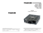
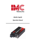
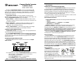
Compact Media Converter
Installation Guide
LHC001A - LHC002A - LHC003A
LHC004A - LHC005A - LHC006A
Black Box’s Compact Media Converter is a low-cost, preconfigured, IEEE
802.3 single-conversion media converter that converts between 100Base-TX
twisted pair and 100Base-FX multi-mode or single-mode fiber. It is available
with one RJ-45 connector for the twisted pair port and one pair ST or SC
connectors for the fiber port.
Compact Media Converter is a 1U high, standalone unit that includes
diagnostic LEDs for each port and a universal (100-240 VAC) power supply. The
following Compact Media Converter versions are available:
100B TX - 100B FX — 100Base-TX twisted pair/100Base-FX 1300 nm multimode fiber; includes one RJ-45 connector and one pair ST (LHC001A) or SC
(LHC002A) connectors
100B TX - 100B FX SM — 100Base-TX twisted pair/100Base-FX 1300 nm
single-mode fiber; includes one RJ-45 connector and one pair ST
(LHC003A) or SC (LHC004A) connectors
100B TX - 100B FX SM/PLUS — same as above with higher power budget;
includes one pair ST (LHC005A) or SC (LHC006A) connectors
Installing Compact Media Converter
Compact Media Converter comes ready to install. The only adjustments that
may need to be made come after installation.
To install Compact Media Converter, first make sure that the unit is placed on
a suitable flat surface. Attach the cables between the Compact Media Converter
and each device that will be interconnected, then plug the unit into a reliable,
filtered power source.
Configuring Compact Media Converter
The following diagram shows the switches and connections on Compact
Media Converter.
Figure 1: Compact Media Converter TX/FX, Front View
Once installed, you can configure Compact Media Converter for the following:
•
Select a crossover or pass-through connection for the twisted
pair port (default = OUT/crossover)
•
Enable Auto-Negotiation (default = DOWN/disabled)
•
Enable FiberAlert (default = DOWN/disabled)
Note: LinkLoss is an additional feature that can be enabled before installation.
1
LinkLoss is disabled as a factory default. See Enabling and Using LinkLoss for
more information.
Twisted Pair Crossover/Pass-Through Switch
The twisted pair port on Compact Media Converter has one RJ-45 connector
for a single shielded or unshielded twisted pair link segment, and features a
push-button switch, located next to the twisted pair connector, for selecting a
crossover workstation connection or pass-through repeater/hub connection.
Select a pass-through connection by pressing the push-button IN. A crossover
connection is selected when the push-button is OUT.
If uncertain whether a crossover or pass-through connection is needed, set the
push-button to the position that makes the link LED glow.
About FiberAlert and LinkLoss
Compact Media Converter comes with the following troubleshooting features:
• FiberAlert
• Twisted Pair LinkLoss (a.k.a. "TX LinkLoss," or just "LinkLoss")
• Fiber LinkLoss (a.k.a. "FX LinkLoss")
FiberAlert and LinkLoss are advanced troubleshooting features that can help
you locate "silent failures" on your network. However, it is vital that you
understand exactly how FiberAlert and LinkLoss work, and how they will react in
your network configuration, before attempting to install the enclosed module(s).
Installing modules without understanding the effects of FiberAlert and
LinkLoss can cause perfectly functioning units to appear flawed or even dead!
If you are unfamiliar with FiberAlert and LinkLoss, the manufacturer strongly
encourages you to read the following information.
About Link Integrity
During normal operation, link integrity pulses are transmitted by all point-topoint Ethernet devices. When a Compact Media Converter receives valid link
pulses, it knows that the device to which it is connected is up and sending pulses,
and that the copper or fiber cable coming from that device is intact. The
appropriate “LINK” LED is lit to indicate this. The Compact Media Converter also
sends out link pulses from its copper and fiber transmitters, but normally has no
way of knowing whether the cable to the other device is intact and the link pulses
are reaching the other end. The combination of FiberAlert and LinkLoss allows this
information to be obtained, even when physical access to a remote device (and
its link integrity LED) is not available.
What Is FiberAlert?
FiberAlert lets you know when a fault
occurs on your fiber loop by stopping
data transmissions and affecting fiber
LEDs on both sides of your network. If
a media converter is not receiving a
fiber link, FiberAlert disables the media
converter's fiber transmitter, thus mirroring the link status of the opposite end of
the fiber. Both fiber link LEDs on either end of the link should extinguish,
alerting you to the fault.
2
Using FiberAlert, a local site administrator is notified of a fault and can quickly
determine where a cable fault is located without having to go to the remote site.
NOTE: FiberAlert should only be enabled on one side of a media
conversion. Enabling it on both sides would keep both transmitters off
indefinitely.
What Is Twisted Pair LinkLoss?
Twisted Pair LinkLoss (a.k.a. “LinkLoss”) functions much like FiberAlert in that
faults on one port are mirrored on the other. In the case of LinkLoss, however, a
fault on the fiber port is
passed to the Ethernet
FiberAlert/LinkLoss Compared
twisted pair port.
Fault Location
Disabled LEDs
Feature
Fiber
If a media converter is FiberAlert
Fiber
not receiving a fiber link, TX LinkLoss
Fiber
Twisted Pair
LinkLoss disables the
Twisted Pair
Fiber
FX LinkLoss
transmitter on the media
converter's twisted pair port. This results in a loss of link on the remote twisted
pair device.
What Is Fiber LinkLoss?
Fiber LinkLoss lets you know when a fault occurs on the twisted pair portion of
your network by affecting the fiber link LED on the remote fiber device. When
the twisted pair port on the media converter is not receiving a link pulse, Fiber
LinkLoss turns off the media converter's fiber transmitter. This results in a loss of
fiber link to the remote fiber device (media converter, switch, fiber hub, etc.),
which extinguishes its LED, thereby letting you know that a fault exists
Auto-Negotiation on Compact Media Converter
Auto-Negotiation is available on Compact Media Converter. When AutoNegotiation is enabled, the media converter negotiates as a 100 Mbps FullDuplex device; if the device the Compact Media Converter is connected to can
operate at 100 Mbps Full-Duplex, a link will be established.
If the twisted pair port on the other device does not have the ability to autonegotiate, or if a 100 Mbps Half-Duplex connection is desired, Auto-Negotiation
on Compact Media Converter must be disabled. Half- and Full-Duplex settings
must be manually set and match on both devices to which Compact Media
Converter is connected. The diagram below shows a typical application,
followed by a table with three possible configurations.
Enabling FiberAlert and Auto-Negotiation
FiberAlert and Auto-Negotiation are each configured on Compact Media
Converter by adjusting a two-position switch on the faceplate next to the fiber
connectors. The switch for FiberAlert is labeled “FA” and Auto-Negotiation is
labeled “AN.” Enable these features by moving the corresponding switch to the
up (ON) position. Disable (default) by moving the switch to the down (OFF)
position.
Enabling TX and FX LinkLoss
In order to enable these functions, you will need to remove the cover from
the unit and place the jumpers accordingly. Follow these instructions:
1) Make sure that there is no power
going to the unit by
UNPLUGING THE POWER
CORD!
2) Using a phillips screwdriver,
remove the screws on the
corners of the cover.
3) Remove the cover. After doing
so, find the three-pin jumpers
JP1 and JP2. JP1 toggles the TX
LinkLoss feature and JP2 toggles
the FX LinkLoss feature. See Figure 2 for location and settings.
4) Replace the
cover and
tighten the
screws to
secure the
cover.
JUMPER CONFIGURATION CHART
Jumper
Position
ON
(pins)
OFF
(pins)
Factory
Default
TX LINKLOSS
JP1
1-2
2-3
Off
FIBER LINKLOSS
JP2
1-2
2-3
Off
Feature
Using FiberAlert and LinkLoss
In a typical central site to remote site media conversion, the manufacturer
recommends you enable your media converters’ troubleshooting features as
follows:
FiberAlert:
TX LinkLoss:
FX LinkLoss:
Remote Site Only
Main and Remote Site
Remote Site Only
This will ensure that any faults, no matter where they occur, can be detected
by an administrator located at the central site.
Installation Troubleshooting
•
3
During installation, first test your fiber and twisted pair connections
with all troubleshooting features disabled. Then enable these features,
if desired, just before final installation. This will reduce the features’
interference with testing.
4
•
•
To test Compact Media Converter by itself, you must have an
appropriate fiber patch cable. First, connect Compact Media Converter
to the twisted pair device with a twisted pair cable. Next, loop a single
strand of fiber from the transmit port to the receive port of your media
converter. Finally, verify that you have both twisted pair and fiber link
on your Compact Media Converter.
Make sure that you are using the appropriate twisted pair cable or have
the crossover/pass-through button on the Compact Media Converter set
correctly.
LED Operation
Compact Media Converter features four diagnostic LEDs. They are:
FX RCV
TX LNK
FA
FX LNK
Blinks yellow when module is receiving data.
Glows green when a twisted pair link is established.
Glows green when FiberAlert is enabled.
Glows green when a fiber link is established.
Specifications
Environmental
Operating Temperature: 32° - 104° F (0° - 40° C)
Storage Temperature: 20° - 160° F (-20° - 70° C)
Humidity: 5 - 95% (non-condensing)
Power
AC Input Load: 100/240V± ~ 50/60 Hz, 0.1/0.05A
Heat generated: 25 BTU/hr.
Dimensions
1.50”H x 4.65”W x 4.43”D (3.8 cm x 11.8 cm x 11.3 cm)
1.3 lbs. (0.6 kg)
Black Box Customer Service Information
(724) 746-5500 7 a.m. Monday to midnight Friday; 8 a.m. to
4 p.m. Saturday (EST)
FAX:
(724) 746-0746 7 a.m. Monday to midnight Friday; 8 a.m. to
4 p.m. Saturday (EST)
Mail Order:
Black Box Corporation, 1000 Park Drive, Lawrence,
PA 15055-1018
Technical support, phone and fax orders 24 hours a day.
connecting the fiber cable to the device. Assure that the fiber is properly
terminated, polished and free of any dust or dirt, and that the location is as
free from dust and dirt as possible.
3) Store spare caps in a dust-free environment such as a sealed plastic bag or
box so that when reinstalled they do not introduce any contamination to the
optics.
4) Should it be necessary to disconnect the fiber device, reinstall the protective
dust caps.
5) If you suspect that the optics have been contaminated, alternate between
blasting with clean, dry, compressed air and flushing with methanol to
remove particles of dirt.
Electrostatic Discharge Precautions
Electrostatic discharge (ESD) can cause damage to your add-in modules.
Always observe the following precautions when installing or handling an add-in
module or any board assembly.
1) Do not remove unit from its protective packaging until you’re ready to
install it.
2) Wear an ESD wrist grounding strap before handling any module or
component. If you do not have a wrist strap, maintain grounded contact
with the system unit throughout any procedure requiring ESD protection.
WARNING! Integrated circuits and fiber optic components are extremely susceptible to electrostatic discharge
damage. Do not handle these components directly unless you are a qualified service technician and use tools and
techniques that conform to accepted industry practices.
3) Hold boards by the edges only; do not touch the electronic components or
gold connectors.
4) After removal, always place the boards on a grounded, static-free surface,
ESD pad or in a proper ESD bag. Do not slide the board over any surface.
CALL:
Please contact Black Box for complete warranty, FCC and Safety Certification information.
Fiber Optic Cleaning Guidelines
Fiber Optic transmitters and receivers are extremely susceptible to
contamination by particles of dirt or dust, which can obstruct the optic path and
cause performance degradation. Good system performance requires clean optics
and connector ferrules.
1) Use fiber patch cords (or connectors, if you terminate your own fiber) only
from a reputable supplier; low-quality components can cause many hard-todiagnose problems in an installation.
2) Dust caps are installed by the manufacturer to ensure factory-clean optical
devices. These protective caps should not be removed until the moment of
5
1000 Park Drive • Lawrence, PA 15055-1018 USA
TEL: (724) 746-5500 • FAX: (724) 746-0746
E-MAIL: [email protected]
WEB: http://www.blackbox.com
© 2001 Black Box Corporation. All rights reserved.
The information in this document is subject to change without notice. Black Box Corporation assumes no responsibility for any
errors that may appear in this document. Specific brands and product names may be trademarks and are the property of their
respective companies.
Document Number 55-80126BB-01 C0
May 2001
6