1
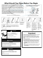
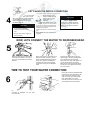
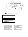
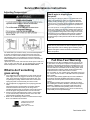
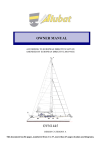
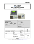
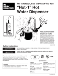
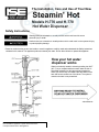
The Installation, Care and Use of Your New
Steamin' Hot
Models H-770 and H-778
Hot Water Dispenser
Safety Instructions
Warnings alert you to hazards or unsafe practices which could result in severe
personal injury or death.
Cautions alert you to hazards or unsafe practices which could result in minor personal injury
or product/property damage.
Please be certain that the person who installs or uses this appliance carefully reads and understands the Safety Instructions
contained in this manual. This appliance produces extremely hot water. Do not allow children to operate this appliance.
How your hot water
dispenser works
Water is electrically heated to a brewing/cooking hot 190°F
(88° C)* by a compact tank that mounts under the sink. A
thermostat maintains it at this approximate temperature.
When you turn the tap, cold water enters the bottom of the
tank and forces hot water out of the faucet. The system is
vented so the tank is not pressurized.
*APPROXIMATE
Important
Do not install this appliance in public areas where there
is unsupervised access to this appliance.
What Should You Know Before You Begin
Connecting the dispenser to your regular water supply requires no special
plumbing. All details are covered in the installation instructions. Be sure that all
plumbing connections conform to your applicable local codes. If your water supply
contains sand, grit or other suspended particles, the use of a filter is recommended. The filter should not result in the water pressure to the dispenser dropping below 20 pounds per square inch (138kPa). This could prevent the unit from
aspirating properly.
A standard 115-volt grounded electrical outlet is required under the sink for the
dispenser's electrical power. The current drain is 6.5 amps only when the tank is
heating. Assure that all electrical wiring and connections conform to applicable
codes. Note: The wall outlet to your dispenser must have power supplied to
it continuously and must be fused. It should not be controlled by the same
wall switch that operates your disposer.
These are the tools and materials you will need
These are the tools you may need
Pliers
Screwdrivers.
Phillips and flat
blade
Adjustable
wrench
1/2" - 9/16" open
end wrench
Cold water line within 2’ (61cm)of the dispenser. A
shutoff valve to connect the dispenser to the cold
water line (see step 4 for examples of connections
that can be used).
WARNING
Personal Injury
• Dispenses 190°F (88° C) water which can
instantly cause scalds or burns. Use care
when operating this feature.
• Do not allow children to operate this
appliance.
WARNING
Fire Hazard
• To minimize possibility of fire, do not store flammable items
such as rags, paper or aerosol cans near the tank. Do not
store or use gasoline or other flammable vapors and liquids in
the vicinity of this or any other appliance.
WARNING
Personal Injury
• This tank is a non-pressure tank. Do not modify this system.
Do not close vent tube or connect other type faucets or valves
to the tank.
• Use only the faucet supplied.
115-volt grounded
outlet within 30
inches (76 cm) of
the dispenser
Hand drill. If you
have a galvanized water supply pipe, you may
need a nonelectric hand drill
to make a small
hole.
Basin wrench. If you
intend to use the
hand sprayer hole in
your sink for your dispenser, you may
need a basin wrench
and a 1/8" plug or a
1/4" cap for the faucet
spray hose line. See
item 1 of Installation
instructions for
details.
Chassis
punch.
If you need to
punch a mounting hole in your
stainless steel
sink you may
need a 1-1/4"
(3.2 cm) chassis
punch.
Important
• Any time you plan on being away from home for an extended
period of time, unplug the unit's electrical cord.
• If your unit is installed in a summer home and you want to
prepare it for winter to protect against freezing or if periodic
draining is necessary in a heavy mineral area, follow these
steps:
A. Disconnect electricity.
B. Turn dispenser knob and allow the water to flow until cool.
C. Shut off the dispenser water supply at the outlet valve.
D. Remove the drain screw located in the center of the bottom of your dispenser tank and drain the water into an
empty pail.
E. After emptying the tank, reinstall screw into bottom of
tank.
F. When you put the unit back into operation, be sure to refill
tank with water before reconnecting the electrical plug.
Review step #9.
FIRST, LET'S REMOVE YOUR EXISTING
OK... Let's
get on with
the
installation
1
A
If you have a spray unit like this one on your
B A nut connects the spray hose to a tube at the
kitchen sink, the hole is perfect for mounting
your Hot Water Dispenser's head.
bottom of your faucet. FIRST, BE SURE
FAUCET IS TURNED OFF. Then remove this nut.
RINSE SPRAY AND HOSE
What if you don't use a
sprayer hole?
C Now pull the spray head and hose entirely out
D Next, remove the nut from the bottom of the
Of the hole. Then plug the faucet tube opening
With either a 1/8” plug or 1/4" cap (not supplied).
washer flange in the spray hole. If you don’t
Have enough room for an ordinary wrench, you
May need a basin wrench.
You can cut a mounting hole
through a stainless steel sink with
a 1-1/4" (32mm) chassis punch.
Rent or purchase one at your
hardware or electrical supply store.
Or, mount the Hot Water
Dispenser's head in a 1-1/4"
(32mm) hole drilled through your
countertop with an expandable
wood bit. Don't attempt to drill a
hole through a cast iron or porcelain covered sink unless you have
the proper tools and skills.
STRAIGHTEN THE DISPENSER TUBES
2
The tubes to the dispenser head are curved for easier packing and
shipping. To straighten, hold the head down with one hand while working
the lubes down slowly with your other hand. See Caution, step 8.
NOW, WE INSTALL THE DISPENSER HEAD
3
A
Place the dispenser head with #10-24 mounting screw and gasket attached down through
the mounting hole. Then while an assistant holds
the dispenser head in place, secure the head as
shown in steps B and C.
B
Working from below sink, place semi-circular
metal mounting washer over the mounting
screw.
C
Now, simply tighten the screw and your dispenser head will be secured to the sink.
LET'S MAKE THE WATER CONNECTION
Connect to the cold water supply line
The recommended
connection can be made using a shutoff
valve. This is a more complex installation
and should only be attempted by an
experienced installer with the proper
knowledge and tools.
CAUTION
Product Damage
• Do not use paste -type pipe
sealants on water line connec
tions.
Doing so may result in clogging of
water passages.
Where plumbing codes
permit, a saddle valve (not
supplied) can be used to
supply water to the
dispenser.
If the saddle valve is to be
used on copper pipe it is not necessary
to pre-drill any holes. Simply follow the
directions for "self-piercing attachment"
included with the valve.
(Attach the valve to a cold water supply
line)
Note: Saddle valves are susceptible to
clogging.
WARNING
Electric Shock Hazard
• Never use an electric drill to drill
into water pipes. It can result in an
electric shock. Use a non-electric
hand drill.
NOW, LETS CONNECT THE WATER TO DISPENSER HEAD
Before you start, open the valve and let
a small amount of water run through it
into a pan. This will flush the line of any
sediment.
When connecting to a compression type
fitting tee or valve, remove the nut and
ferrule (a rounded brass fitting) from the
valve. Then, place the nut followed by
the ferrule over the end of the longest
copper tube coming from the dispenser
head.
Push the tube end all the way into the
valve opening or tee fitting. Hold the tube
end in position and push the ferrule
down as far as it will go. Now, tighten the
nut over the ferrule with your fingers.
Make sure the tube end is going straight
into the hole. Then tighten the nut firmly
with a 1/2" wrench.
TIME TO TEST YOUR WATER CONNECTION
Place a pan under the unattached tubes
and have your handy assistant turn the
knob on the faucet. You should see
water coming out of the small copper
tube. Let the water run for a few
seconds to flush out the lines, then tell
your assistant to turn the faucet off.
Open the valve all the way and see if your
connection is watertight. If it isn't, redo
your connection.
NOW, LET'S MOUNT THE TANK
7
C Hang the tank on the bracket. There is room
to adjust the bracket, if necessary.
A Mount the tank on either a back
B Position the metal mounting
or side wall. Start by holding
tank up and making sure the tubes
reach it. When you have decided
where you want to mount the tank,
mark the position of the top of the
tank on the wall with a pencil. Allow
sufficient space for drain screw
access.
bracket about one inch (25mm)
below the mark on the wall and
attach it through the slots with the
two screws provided. The use of (2)
#8 plastic anchors (not provided) is
recommended for mounting screws in
any material other than wood.
CAUTION
•
•
Product damage
Do not connect electric power until
tank is filled with water (step 9).
Failure to do so may damage heating
element or thermal safety fuse and
will void your warranty.
LET'S MAKE THE FINAL PLUMBING CONNECTIONS
8
A Two copper tubes remain
CAUTION
unconnected. Attach the tube with the
larger diameter to the fitting in the
center of the tank exactly the way you
attached the tube in step 5.
Nuts and ferrules for both unconnected copper tubes are in the plastic bag
in your dispenser kit.
Flow restriction
Make sure all bends in the tubes are
smooth and unkinked before you proceed. All connections are compression
fittings, so don't use any sealant compound. Make the fittings snug, but don't
overtighten. Do not extend the two water
lines to the tank beyond the 16" (40cm)
provided.
B
Next, connect the remaining unattached
copper tube the same way to the fitting
at the back of the unit.
C Finally, use a pliers to connect the clear
plastic tube to the remaining unconnected fitting on the tank using the hose clamp
provided.
Note: The clear
plastic tube in
Step C is a vent
line. Insure it is
not twisted or
obstructed.
FILL THE TANK...IT'S READY
9
A Make sure the water supply
B After about one minute, the
valve is turned on. Then turn
the dispenser knob and hold it
open.
tank will fill and water will
begin coming out of the faucet.
Turn off the faucet and check all
connections for leaks.
DO NOT PLUG IN YET!
WARNING
Fire/Product Damage
Do not remove or alter the thermal safety fuse.
If you suspect the thermal fuse is open, contact your
Authorized Service Center
ISE
WARNING
Product Damage
Do not connect electric power until tank is filled with
Failure to do so may damage heating element or
thermal
fuse
andsafety
will void your warranty.
Until you have read and understood the following:
Once the electrical cord is plugged in, it will take ten to
15 minutes for the water to reach its 190°F (88°C)*
temperature.
However, when the 190°F (88°C)* temperature is
being reached, you can expect a gurgling or hissing
sound within the tank which is normal. You might also
experience steaming and/or spitting hot water to come
out of the faucet without turning it on. This also is a
normal function on any initial start up.
Now, carefully turn on the faucet for about 20 seconds
to draw off that steaming water and allow the water in
the tank to reheat. Repeat this step one or two more
times. This allows the functional parts of the dispenser
to heat up evenly and work in balance, preventing the
steaming and spitting condition. If steam is still emitted
from the faucet, a thermostat adjustment may be necessary to slightly decrease the water temperature.
(See adjusting temperature procedure). Your dispenser
should now be operating properly.
Note: The dispenser perks like a coffee percolator
just before the electric thermostat shuts it off. The
rumble is caused by gas bubbles being driven off by
the boiling water. This is part of the regular operation
or the dispenser.
High altitudes: High elevations (Denver, Colorado, etc.)
may require the thermostat to be lowered to keep the
water from boiling (see adjusting temperature procedure).
*APPROXIMATE
Specifications
Model H-778
Commercial
Model only:
This model comes with a 4"
chrome extension sleeve for
the tap. To attach, slide the
sleeve up and over the
copper tubes and insert it into
the bottom of the tap
assembly as shown. (No
gasket is provided). Then
follow step 3 to attach to sink,
using longer screw provided.
Sink or Counter
This unit is designed
to be installed in
sinks or countertops
of 3/4" (1.9 cm)
thickness or less. For
any surface thicker
than this, obtain a
longer #10-24
mounting screw.
Capacity
1/2 gallon (1.9L), up to 60 cups of 190°F (88"C) water
per hour. Model 778: 100 cups per hour.
Electrical
750 watts, 6.5 amps, 115 volts A.C. Grounding 3-wire
cord and plug provided. Model 778: 1300 watts, 11.3
amps, 115 volts A.C.
Thermostat
Snap-action, adjustable from 140°F to 200°F (60° to
94°C). Factory pre-set at approximately 190°F (88°C).
Insulation
Meets UL 94HF-1 flammabllity specification
Valve
Instant, self-closing
Shipping weight
9 Ibs. (4 kg.)
Service/Maintenance Instructions
Adjusting Temperature
What if water is dripping from
the spout?
If water drips from the spout, draw 2 or 3 cupfuls while unit is
heating. This will drain any water out of the unit's expansion
chamber. If water still drips prior to the automatic thermostat
shutting off (you can hear it), turn thermostat to a slightly lower
temperature setting. See thermostat adjustment procedure at
left.
If the water pressure occasionally drops below 20 pounds per
square inch (138kPa), the expansion chamber of the tank may
not be draining properly. In such a case, water may drip from
the spout until the incoming water is hot enough to turn off the
thermostat. As soon as adequate water pressure is restored,
the next drawing of water will clear the expansion chamber.
Occasional drops in water pressure will not harm the operation
of your unit.
NOTE: Use only mild cleaners to clean the dispenser spout and
plastic components. Use of cleaning agents containing acids,
alkalines and organic solvents will result in deterioration of
plastic components.
The thermostat is pre-set at the factory. If a thermostat adjustment
is required, unplug the power cord and remove the screw and
access cover. Insert a small screwdriver in the slot of the thermostat adjusting screw. Turn clockwise 1/2 notch to increase the
water temperature and counterclockwise 1/2 notch to decrease the
water temperature.
replace the access cover and reconnect electric power. Draw 3 or
cups of water and allow unit to heat. Repeat the process until
desired temperature is reached. Do not allow water to boil.
What to do if something
goes wrong
1. If the dispenser's flow of water slows or stops, make sure the
water supply valve is not plugged or turned off. To unplug the
valve, turn it all the way off and then open it all the way. This
may dislodge any foreign material. If this does not work, then
unplug the power cord and contact your service center.
2. Be sure dispenser is plugged firmly into a properly grounded
outlet.
Check that fuses and circuit breakers are working. Reread
instruction booklet to assure that you are using correct
operating procedure. Many unnecessary service calls result in
the service agent doing what the owner can do for himself.
3. Contact your local authorized service center. For the location
of your nearest factory authorized service center call 1-800558-5700 USA (1-800-367-9811 Canada).
4. Write to us if a satisfactory solution Is not reached in the steps
above. Our address is shown below.
Full One-Year Warranty
Beginning from the date of installation through one year of use
in your home, we will repair or replace at no charge defects in
material or workmanship which appear in the dispenser. If your
dispenser is replaced rather than repaired, the warranty on the
new unit shall be for the duration of the remaining portion of the
original dispenser's warranty. Please call the nearest Factory
Authorized Service Center when service is needed.
For the location of your nearest factory authorized service center, call this toll free number: 1-800-558-5700 USA (1-800-3679811 Canada).
This full one-year warranty applies only if the unit is installed in
accordance with these installation instructions, is used on
circuits and currents specified, and has had normal use and
service.
The foregoing warranty does not apply to damage or inoperation resulting from accident, alteration, misuse, abuse, improper
installation, installation not in accordance with these instructions or local electrical and/or plumbing codes or shows evidence of having been started up "dry". We do not assume any
responsibility for consequential damage.
IN-SINK-ERATOR DIVISION
EMERSON ELECTRIC CO.
4700 21st STREET
RACINE, WIS., 53406-5093
Part Number 42752