1
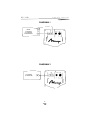
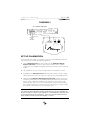
powered subwoofer
®
THE ORIGINAL BIPOLAR LOUDSPEAKER
o w n e r s
TM
m a n u a l
BPS-400
PRINTED IN CANADA
7AIMS400
owners
manual
BPS-400
IMPORTANT SAFETY INSTRUCTIONS
•
Read Instructions - All safety and operating instructions should be read before the
product is operated.
•
Retain Instructions - The safety and operating instructions should be retained for
future reference.
•
Heed Warnings - All warnings on the product and in the operating instructions
should be adhered to.
•
Follow Instructions - All operating and use instructions should be followed.
•
Cleaning - Unplug this product from the wall outlet before cleaning. Do not use
liquid cleaners or aerosol cleaners. Use a damp cloth for cleaning.
•
Attachments - Do not use attachments not recommended by the product
manufacturer as they may cause hazards.
•
Water and Moisture - Do no use this product near water - for example, near
a bath tub, wash bowl, kitchen sink, or laundry tub; in a wet basement; or near
a swimming pool.
•
Ventilation - Slots and openings in the cabinet are provided for ventilation and to
ensure reliable operation of the product and to protect it from overheating, and
these openings must not be blocked or covered. They should also never be blocked by
placing the product on a bed, sofa, rug, or other similar surface.
This product should not be placed in a built-in installation such as a bookcase or rack
unless proper ventilation is provided or the manufacturer’s instructions have been
adhered to.
•
Power Sources - This product should be operated only from the type of power
source indicated on the marking label. If you are not sure of the type of power
supply to your home, consult your product dealer or local power company.
For products intended to operate from battery power, or other sources, please refer
to the operating instructions.
•
Grounding or Polarization - This product may be equipped with a polarized
alternating-current line plug (a plug having one blade wider than the other).This plug
will fit into the power outlet only one way.This is a safety feature. If you are unable to
insert the plug fully into the outlet, try reversing the plug. If the plug should still fail to
fit, contact your electrician to replace your obsolete outlet. Do not defeat the safety
purpose of the polarized plug.
1
BPS-400
owners
manual
•
Power Cord Protection - Power-supply cords should be routed so that they are
not likely to be walked on or pinched by items placed upon or against them, paying
particular attention to cords at plugs, convenience receptacles, and the point where
they exit from the product.
•
Overloading - Do not overload wall outlets or extension cords, as this can result in
a risk of fire or electric shock.
•
Object and Liquid Entry - Never push objects of any kind into this product
through openings as they may touch dangerous voltage points or short-out parts that
could result in a fire or electric shock. Never spill liquid of any kind on the product.
•
Servicing - Do not attempt to service this product yourself as opening or removing
covers may expose you to dangerous voltage or other hazards. Refer all servicing to
qualified service personnel.
•
Heat - The product should be situated away from heat sources such as radiators,
heat registers, stoves, or other appliances (including amplifiers) that produce heat.
•
Non-use Periods - The power cord of the product should be unplugged from the
outlet when left unused for a long period of time.
•
Damage Requiring - The product should be serviced by qualified service
personnel when:
A The power-supply cord or the plug has been damaged; or
B. Objects have fallen, or liquid has been spilled into the appliance; or
C. The product has been exposed to rain; or
D. The appliance does not appear to operate normally or exhibits a marked change
in performance; or
E. Product has been dropped, or the enclosure damaged.
2
owners
manual
BPS-400
RADIO FREQUENCY EMISSIONS
This equipment has been tested and found to comply with the limits for a Class B
digital device, pursuant to part 15 of the FCC Rules. These limits are designed to
provide reasonable protection against harmful interference in a residential installation.
This equipment generates, uses and can radiate radio frequency energy and, if not
installed and used in accordance with the instructions, may cause harmful interference
to radio communications. However, there is no guarantee that interference will not
occur in a particular installation. If this equipment does cause harmful interference to
radio or television reception, which can be determined by turning the equipment off
and on, the user is encouraged to try to correct the interference by one or more of the
following measures:
•
•
•
•
Re-orient or relocate the receiving antenna.
Increase the separation between the equipment and receiver.
Connect the equipment into an outlet on a circuit different from that to which the
receiver is connected.
Consult the dealer or an experienced radio/TV technician for help.
TABLE OF CONTENTS
Safety Instructions . . . . . . . . . . . . . . . . . . . . . . . . . . . . . . . . . . . . . . . . . . . . . . . . . .1
Introduction . . . . . . . . . . . . . . . . . . . . . . . . . . . . . . . . . . . . . . . . . . . . . . . . . . . . . .4
Features & Operating Controls . . . . . . . . . . . . . . . . . . . . . . . . . . . . . . . . . . . . . . .4
Room Acoustics & Subwoofer Placement . . . . . . . . . . . . . . . . . . . . . . . . . . . . . . . .6
Subwoofer Connection to
your Audio/Video System . . . . . . . . . . . . . . . . . . . . . . . . . . . . . . . . . . . . . . . . . . . .7
Set-up Calibration . . . . . . . . . . . . . . . . . . . . . . . . . . . . . . . . . . . . . . . . . . . . . . . . . .9
Specifications . . . . . . . . . . . . . . . . . . . . . . . . . . . . . . . . . . . . . . . . . . . . . . . . . . . . .10
Warranty . . . . . . . . . . . . . . . . . . . . . . . . . . . . . . . . . . . . . . . . . . . . . . . . . . . . . . . .11
3
BPS-400
owners
manual
INTRODUCTION
We are proud to welcome you as a new owner of a Mirage BPS-400. Mirage subwoofers are
the result of extensive research into accurate bass reproduction and represent the leading edge
in subwoofer design and performance.The finest components and cabinet materials combined
with sophisticated manufacturing and quality control procedures ensure many years of
exceptional performance and listening pleasure.
PLEASE TAKE TIME TO READ ALL OF THE INSTRUCTIONS CONTAINED IN THIS
MANUAL TO MAKE CERTAIN YOUR SYSTEM IS PROPERLY INSTALLED AND
FUNCTIONING CORRECTLY.
Be sure to unpack your subwoofer carefully. Retain the carton and all packing material for
future use.
FEATURES AND OPERATING CONTROLS
All operating controls are conveniently located on the amplifier panel mounted on
the rear of your subwoofer cabinet.
FEATURES
Auto-On/Auto-Off Circuit
Your subwoofer is equipped with a special “Auto-on/Auto-off ” circuit. This circuit
automatically turns your subwoofer on as soon as it senses a program signal. At a
predetermined time after the program signal ends, this circuit automatically
turns the subwoofer off.
Clipping Protection Circuit
Many powered subwoofers on the market today produce distorted sounds as a result
of clipping at high input levels. Mirage’s proprietary Clipping Protection Circuit (CPC)
continuously senses the input signal level and automatically adjusts to prevent clipping of
the wave form, maintaining undistorted bass reproduction.
4
owners
manual
BPS-400
Pulse Width Modulation
Your new BPS-400 incorporates a revolutionary new power amplifier technology called
Pulse Width Modulation (PWM).
The 400 watt PWM amplifier used in the BPS-400 has much higher efficiency (90%) than
typical analog amplifiers (20%) and thus generates much less heat (typically 1/5).
The PWM amplifier can generate much higher power output than comparable analog
amplifiers (400W vs 100-200W).
The 400 watt PWM amplifier is capable of generating very high sound pressure levels
125dB @ 18Hz.
Low-Level RCA Input Jacks
The RCA input jacks allow you to connect your subwoofer to any of the following:
(a)
(b)
(c)
(d)
(e)
(f)
Pre-amplifier outputs
Audio/Video processor outputs
The "subwoofer output" from an Audio/Video receiver
Any integrated receiver with pre-out facilities
The audio output from your stereo television or computer sound cards
An External Active Crossover.
See "Subwoofer Connection to your Audio/Video System".
OPERATING CONTROLS
Subwoofer Level Control
This rotary control adjusts the output level of your Mirage subwoofer and should be
used to balance the level of the subwoofer with that on your main/satellite speakers.
See “Set-up Calibration”.
LP Filter (Low-pass) Control
This rotary control adjusts the high frequency roll-off of the subwoofer. Continuously
variable from 50Hz to 100Hz, it is used to precisely match the subwoofer bass
reproduction with that of your main/satellite speakers. See “Set-up Calibration”.
5
BPS-400
owners
manual
ROOM ACOUSTICS AND
SUBWOOFER PLACEMENT
Mirage subwoofers can be placed virtually anywhere in your listening room without
significantly affecting the stereo image of your main speakers. However, interactions
between any subwoofer and room acoustic properties will have some impact on the
overall bass performance. Reading this section will help you to find a placement for the
subwoofer in your room which will yield the best bass performance.
CAUTION: MIRAGE SUBWOOFERS HAVE A BUILT-IN AMPLIFIER AND MUST
HAVE ADEQUATE VENTILATION FOR COOLING PURPOSES. DO NOT PLACE
THE SUBWOOFER NEAR HEAT SOURCES, OR ANYTHING WHICH MIGHT
OBSTRUCT VENTILATION.
Although a clear path between the subwoofer and listening position is not required, it
is important to leave approximately 4 inches of clearance between the subwoofer and
walls or room furnishings. Generally, shorter runs of hook-up cables are preferable
(and easier to hide), therefore locating your subwoofer relatively close to your audio
equipment is often desirable.
The interaction between room acoustics and any subwoofer is closely related to the
subwoofer’s proximity to the walls.Typically, subwoofer placement directly in or close to a
corner will produce the most bass output, placement along one wall but away from a
corner will produce less bass output, and placement of the subwoofer further into the
room will produce the least amount of bass output. It should also be realized that the
corner location, although producing the most bass output often yields ill-defined or
“boomy” bass.The latter two locations will deliver progressively more accurate bass
performance.
SUBWOOFER
SUBWOOFER
MOST BASS OUTPUT,
BUT MAY BE “BOOMY”.
MODERATE BASS OUTPUT WITH
SMOOTHER PERFORMANCE.
SUBWOOFER
LESS BASS OUTPUT, BUT WITH
BEST PERFORMANCE.
We urge you to experiment with various subwoofer placements in your listening room
to find the position which produces “deep and smooth” performance. Often, moving the
subwoofer a foot or two can make a big sonic improvement. Remember to use familiar
musical recordings with an abundance of low frequency information when you
experiment with subwoofer locations.
6
owners
manual
BPS-400
CONNECTING YOUR SUBWOOFER
Using an Integrated Amplifier/Receiver equipped with
pre-out Jacks only (See Diag. 1)
This method uses two standard RCA-to-RCA interconnect cables. First, connect the
amp/receiver's left "PRE-OUT" to the subwoofer jack marked left (L) "LOW LEVEL
INPUT".Then, connect the amp/receiver's right "PRE-OUT" to the subwoofer jack marked
right (R) "INPUT".This method by-passes the subwoofer's built-in high pass crossover, and
your speakers will continue to reproduce bass frequencies.
Using the “Subwoofer Output” of an A/V Receiver
or Processor (See Diag. 2)
This method uses a single RCA-to-RCA interconnect cable to connect the
"SUBWOOFER OUTPUT" jack from your A/V receiver or processor to either the
left or right subwoofer "INPUT".This method does not remove low frequencies from
your main speakers, and they will continue to reproduce bass frequencies.
Using External Crossover (See Diag. 3)
This method uses a single RCA-to-RCA interconnect cable to connect the
"SUBWOOFER OUTPUT" jack from an external crossover to the LFX input of your
subwoofer. This method by-passes the subwoofer's built-in low pass crossover and
level control, thus, all subwoofer functions are controlled by the external crossover.
(See External Crossover Owner’s Manual)
7
BPS-400
owners
DIAGRAM 1
R
PREAMP
A/V RECEIVER
A/V PRECESSOR
INTEGRATED AMP
L
DIAGRAM 2
A/V RECEIVER
A/V PRECESSOR
8
manual
owners
manual
BPS-400
DIAGRAM 3
LFX-1 EXTERNAL CROSSOVER
USE SUB 1
OR
USE SUB 2
SET UP CALIBRATION
For best results when setting up your system, assume your normal listening position and
have another person perform the following adjustments:
1. Set the Subwoofer Level to its zero position. Set the Subwoofer Roll-off
Frequency Control to 50Hz. Set any loudness, bass/treble, and/or equalizer
controls on your preamplifier or integrated amp/receiver to their normal or mid-point
positions.
2. Play a familiar CD, record, or video soundtrack that has substantial bass content.
3. Gradually turn the Subwoofer Level control clockwise until you achieve a neutral
balance between the subwoofer's deep bass output and your main/satellite speakers.
4. Slowly turn the Subwoofer Roll-off Frequency Control clockwise to reach the
best mid bass blend with your main/satellite speakers.This will be the point at which
the bass retains solid impact and fullness. If the mid bass becomes "boomy" or ill
defined, you have gone too far and you should turn the control counter-clockwise to
the best balance point. If the sound is too thin (i.e., male vocals are not full sounding)
then turn the control clockwise to the best balance point.
NOTE: The Subwoofer Level Control is designed to control the balance between
your subwoofer and main/satellite speakers and should not be used as a substitute for
the bass or loudness controls on your amplifier or receiver. Adjust the subwoofer's level
for smoothest low frequency performance. If more bass is desired, advance the bass
and/or loudness controls on your main amplifier or receiver.
9
BPS-400
owners
SPECIFICATIONS
POWER OUTPUT:
400 WATTS
WOOFER:
2 x 12” (30.5cm) BIPOLAR
SOUND PRESSURE OUTPUT:
125 dB in typical room
ACOUSTIC FREQUENCY RESPONSE:
18Hz,
50 - 100, +0 –3dB
LOW PASS FILTER:
50 - 100 Hz @
24dB/Octave
INPUT SENSITIVITY:
L & R 50 mV
LFX 150 mV
DIMENSIONS: H x W x D (in)
(cm)
21.5 x 23.5 x 19.5
54.6 x 59.7 x 49.5
WEIGHT:
110 lb.
50 kg.
SPECIFICATIONS SUBJECT TO CHANGE WITHOUT NOTICE
10
manual
owners
manual
BPS-400
LIMITED WARRANTY POLICY
Warranty in the United States and Canada
Mirage warrants this product to the retail purchaser against any failure resulting from
original manufacturing defects in workmanship or materials.The warranty is in effect for a
period of one (1) year from date of purchase from an authorized Mirage dealer and is
valid only if the original dated bill of sale is presented when service is required.
The warranty does not cover damage caused during shipment, by accident, misuse, abuse,
neglect, unauthorized product modification, failure to follow the instructions outlined in the
owner’s manual, failure to perform routine maintenance, damage resulting from unauthorized repairs or claims based upon misrepresentations of the warranty by the seller.
Warranty Service:
If you require service for your Mirage loudspeaker(s) at any time during the one (1)
year warranty period, please contact: 1) the dealer from whom you purchased the
product(s), 2) Mirage National Service, 203 Eggert Road, Buffalo, N.Y. 14215
Tel: 1-716-896-9801or 3) Mirage Loudspeakers,a division of Audio Products International
Corp., 3641 McNicoll Avenue, Scarborough, Ontario, Canada, M1X 1G5,
Tel: 1-416-321-1800.You will be responsible for transporting the speakers in adequate
packaging to protect them from damage in transit and for the shipping costs to an
authorized Mirage service center or to Mirage Loudspeakers. If the product is returned
for repair to Mirage Loudspeakers in Scarborough or Buffalo, the costs of the return
shipment to you will be paid by Mirage, provided the repairs concerned fall within
the Limited Warranty. Mirage Warranty is limited to repair or replacement of Mirage
products. It does not cover any incidental or consequential damage of any kind. If the
provisions in any advertisement, packing cartons or literature differ from those specified in
this warranty, the terms of the Limited Warranty prevail.
Warranty Outside of The United States and CANADA:
Product warranties may be legislated differently from one country to another. Ask your
local dealer for details of the LIMITED WARRANTY applicable in your country.
IMPORTANT: Please retain the carton and packing material for this Mirage product
to protect it in the event it ever has to be shipped to a service center for repair.
Product received damaged by a service center that has been shipped by the end user in
other than the original packaging, will be repaired, refurbished and properly packaged
for return shipment at the end user’s expense.
11