1
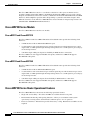
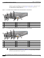
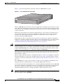
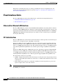
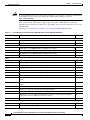
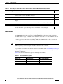
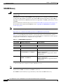
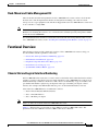
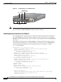
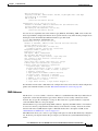
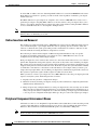
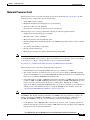
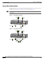
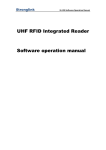
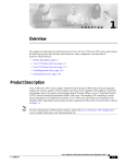
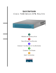
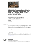
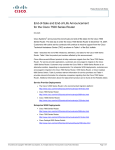
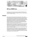
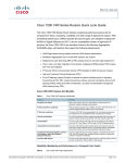
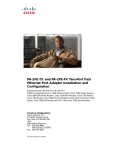
C H A P T E R
1
Product Overview
This chapter provides physical and functional overviews of Cisco uBR7100 series universal broadband
routers and contains the following sections that describe router hardware, major components, and
functions of hardware-related features:
Note
•
Product Description, page 1-1
•
Fixed Interface Units, page 1-6
•
Field-Replaceable Units, page 1-7
•
Functional Overview, page 1-11
Unless otherwise indicated, the term Cisco uBR7100 series in this manual refers to all models of the
Cisco uBR7100 series universal broadband router, including the Cisco uBR7111, Cisco uBR7111E,
Cisco uBR7114, and Cisco uBR7114E routers.
Product Description
The Cisco uBR7100 series universal broadband router is a cable modem termination system (CMTS)
that provides Internet, local area network (LAN), and wide area network (WAN) access for cable
modems and set-top boxes (STBs) over a coaxial cable connection. The router enables high-speed data
services to be packaged similar to basic cable television service or video programming.
The Cisco uBR7100 series routers support two-way data and digitized voice connectivity over a
bidirectional cable television and IP backbone network, using one of the following two standards:
•
The Cisco uBR7111 and Cisco uBR7114 support the Data-over-Cable Service Interface
Specifications (DOCSIS)—DOCSIS 1.0 and DOCSIS 1.1. DOCSIS supports the 6 MHz North
American channel plans using the ITU J.83 Annex B RF standard. The downstream uses a 6 MHz
channel width in the 85 to 860 MHz frequency range, and the upstream supports the 5 to 42 MHz
frequency range.
•
The Cisco uBR7111E and Cisco uBR7114E support the European Data-over-Cable Service
Interface Specifications (EuroDOCSIS)—EuroDOCSIS 1.0 and EuroDOCSIS 1.1. EuroDOCSIS
supports the 8 MHz Phase Alternating Line (PAL) and Systeme Electronique Couleur Avec
Memoire (SECAM) channel plans using the ITU J.112 Annex A RF standard. The downstream uses
an 8 MHz channel width in the 85 to 860 MHz frequency range, and the upstream supports multiple
channel widths in the 5 to 65 MHz frequency range.
Cisco uBR7100 Series and Cisco uBR7100E Series Universal Broadband Router Hardware Installation Guide
OL-5916-01
1-1
Chapter 1
Product Overview
Product Description
The Cisco uBR7100 series router is a cost-effective solution for cable operators, Internet service
providers, multiple tenant units (MTUs), and multiple dwelling unit (MDU) operators such as hotels,
hospitals, and dormitories. The router contains a combination of fixed and modular RF, LAN, and WAN
interfaces, which simplifies operation while still providing a system that is flexible enough to meet
different customers’ needs. The Cisco uBR7100 series chassis includes an integrated upconverter and
embedded dual 10/100BASE-T Ethernet interface.
Cisco uBR7100 Series Models
The Cisco uBR7100 series router has two models.
Cisco uBR7111 and Cisco uBR7111E
The Cisco uBR7111 and Cisco uBR7111E universal broadband routers provide the following fixed
interfaces:
•
A LAN interface with two Ethernet/FastEthernet ports
•
A cable interface with one downstream port and one upstream port. The downstream port can be
output either as an RF signal through the integrated upconverter or as an IF signal for processing by
an external upconverter.
•
A modular single-width port adapter for flexibility in WAN interface connections.
The Cisco uBR7111 router supports DOCSIS cable plants, and the Cisco uBR7111E supports
EuroDOCSIS cable plants.
Cisco uBR7114 and Cisco uBR7114E
The Cisco uBR7114 and Cisco uBR7114E universal broadband routers provide the following fixed
interfaces:
•
A LAN interface with two Ethernet/FastEthernet ports
•
A cable interface with one downstream port and four upstream ports. The downstream port can be
output either as an RF signal through the integrated upconverter or as an IF signal for processing by
an external upconverter.
•
A modular single-width port adapter allows flexibility in WAN interface connections.
The Cisco uBR7114 router supports DOCSIS cable plants, and the Cisco uBR7114E supports
EuroDOCSIS cable plants.
Cisco uBR7100 Series Router Operational Features
The Cisco uBR7100 series routers have the following operational features:
•
Single-side serviceability—All cables and LEDs are available from the rear panel.
•
Environmental monitoring and reporting functions—Allow you to maintain normal system
operation by resolving adverse environmental conditions prior to loss of operation.
•
Front to back airflow—Internal fans provide all necessary cooling. External fan assemblies are not
required.
Cisco uBR7100 Series and Cisco uBR7100E Series Universal Broadband Router Hardware Installation Guide
1-2
OL-5916-01
Chapter 1
Product Overview
Cisco uBR7100 Series Routers Physical Description
•
Online insertion and removal (OIR)—Allows you to add, replace, or remove the modular port
adapter without interrupting the system.
•
Downloadable software—Allows you to load new images into flash memory remotely, without
having to physically access the router, for fast, reliable upgrades.
•
Network management using integrated SNMP agent—Allows you to remotely manage the router.
Cisco uBR7100 series routers support CiscoWorks and CiscoView network management software.
– CiscoWorks—Lets you monitor complex internetworks that use Cisco routing devices and helps
you plan, troubleshoot, and analyze your network. CiscoWorks uses the Simple Network
Management Protocol (SNMP) to monitor and control any SNMP device on the network.
– CiscoView—A graphical SNMP-based device management tool that provides powerful
real-time views of your networked Cisco devices. These views deliver a continuously updated
physical picture of device configuration and performance conditions, with simultaneous views
available for multiple device sessions. CiscoView runs from a centralized network management
site from which you can review, reconfigure, and monitor essential device data from a simple
GUI (that displays information such as dynamic status reports, performance statistics, and
network inquiries) without having to physically check connections for each device, module, or
port at every different or remote location.
Cisco uBR7100 Series Routers Physical Description
Each model includes the following physical features:
•
Cable interface—One downstream and either one or four upstreams, depending on the model of the
router. The cable interface supports the DOCSIS 6 MHz, North American channel plan or the
EuroDOCSIS 8 MHz PAL and SECAM channel plan, depending on the router model.
•
Integrated upconverter—The downstream channel can be output using the router’s integrated
upconverter, producing an RF signal suitable for transmission over the coaxial cable network, saving
both the money and rack space required by an external upconverter. However, for existing cable
plants, the downstream can also be output to an external upconverter.
•
Fixed LAN interface with two ports—10BASE-T/100BASE-TX autosensing Ethernet/Fast Ethernet
(full and half duplex) equipped with an RJ-45 receptacle.
•
Modular port adapter slot—Supports a single-width port adapter, including the
Ethernet/FastEthernet, Serial, high-speed serial interface (HSSI), and ATM interfaces.
•
One console port—Equipped with an RJ-45 receptacle.
•
One auxiliary port—Equipped with an RJ-45 receptacle.
•
Two PCMCIA card slots—Flash disk or flash memory cards contain the default Cisco IOS software
image and can act as backup devices for CMTS and cable modem configuration files.
•
LEDs—LEDs for system ready, power, PCMCIA card slots, for the fixed LAN and cable ports, and
for the modular port adapter interfaces.
•
Up to 256 MB of synchronous dynamic random-access memory (SDRAM) system memory with
64 MB of fixed SDRAM packet memory—Three dual in-line memory modules (DIMMs) on the
network processor board.
•
2 rack-unit (2RU) chassis (front or rear rack-mountable)
•
Single AC power supply, with the option of different power cords, depending on the country of
operation.
Cisco uBR7100 Series and Cisco uBR7100E Series Universal Broadband Router Hardware Installation Guide
OL-5916-01
1-3
Chapter 1
Product Overview
Cisco uBR7100 Series Routers Physical Description
All interface connections and LEDs are located at the back of the router. Figure 1-1 shows the rear panel
of the Cisco uBR7111 and Cisco uBR7111E routers. Figure 1-2 shows the rear panel of the
Cisco uBR7114 and Cisco uBR7114E routers.
Figure 1-1
Cisco uBR7111 and Cisco uBR7111E Universal Broadband Router—Rear Panel View
4
3
2
SLOT 0
5
116834
1
SLOT 1
ACT ACT
PWR
I
DS0
RF
FE 0/0
LNK
1
FE 0/1
DS0
CONS
AUX
SYS
RDY
US0
EN
uBR7114
10
5
7
11
9
8
6
1
ESD receptacle
5
Ground receptacles
9
2
Modular port adapter
6
Power supply
10 Module slot (not used)
3
Fixed Fast Ethernet LAN ports
7
Console and auxiliary ports
11 DS0 RF
4
PCMCIA card slots (covered)
8
US0
Figure 1-2
DS0
Cisco uBR7114 and Cisco uBR7114E Universal Broadband Router—Rear Panel View
4
3
2
SLOT 0
5
116835
1
SLOT 1
ACT ACT
PWR
I
DS0
RF
FE 0/0
DS0
US3
FE 0/1
US2
LNK
1
CONS
US1
AUX
SYS
RDY
US0
EN
uBR7114
13
14
11
9
12
10
5
7
8
6
1
ESD receptacle
6
Power supply
11 US3
2
Modular port adapter
7
Console and auxiliary ports
12 DS0
3
Fixed Fast Ethernet LAN ports
8
US0
13 Module slot (not used)
4
PCMCIA card slots (covered)
9
US1
14 DS0 RF
5
Ground receptacle
10 US2
Note
The grounding receptacles are shown in Figure 1-1 and Figure 1-2 are for the chassis grounding that is
required by the Telcordia specifications for central office use. Power supply grounding is provided by
the three-pronged grounded AC power supply outlet.
Cisco uBR7100 Series and Cisco uBR7100E Series Universal Broadband Router Hardware Installation Guide
1-4
OL-5916-01
Chapter 1
Product Overview
Cisco uBR7100 Series Routers Physical Description
Figure 1-3 shows the front panel for all models of the Cisco uBR7100 series routers.
Cisco uBR7100 Series Front Panel
Cisco uBR7100 SERIES
37637
Figure 1-3
All Cisco uBR7100 series routers have one power supply with one AC-input power receptacle. A power
cable connects the AC-input power supply to the site AC power source. The router’s main power switch
is located next to the AC-input power receptacle. Separate power cords are available, depending on the
country of operation.
On the side of each chassis are two chassis ground receptacles—choose the most convenient set for a
chassis ground connection for a two-hole grounding lug, and the other set can provide a mounting
location for the cable management bracket. On the back of the chassis, there is a receptacle for
electrostatic discharge (ESD) equipment.
Four internal fans draw cooling air into the chassis (back to front) and across internal components to
maintain an acceptable operating temperature. There are four environmental sensors for monitoring the
cooling air as it leaves the chassis. For more information on environmental monitoring, see the
“Environmental Monitoring and Reporting Functions” section on page 6-2.
Caution
To ensure the proper flow of cooling air across the internal components, a port adapter must be installed
in the port adapter slot. If no port adapter is installed, install a blank port adapter (the product number
is MAS-7100-PABLANK=). Slot 5 has a blank face plate. For proper airflow, make sure that a blank
faceplate is always installed in slot 5. (The product number is SM-BLANK=).
The modular port adapter slides into the chassis slot and connects directly to the router; there are no
internal cables to connect.
The port adapter, fixed cable interface, and fixed LAN interface connect to two peripheral component
interconnect (PCI) buses on the router’s backplane that provide a path to packet I/O memory and the
system processor. For more information, see the “Peripheral Component Interconnect Buses” section on
page 1-14.
Cisco uBR7100 series routers can be installed on a tabletop or in an equipment rack. Rubber feet for
tabletop installation are included in the accessory kit that shipped with your router.
A rack-mount and cable-management kit is also standard equipment included with all Cisco uBR7100
series routers when they are shipped from the factory. The kit provides the hardware needed to mount
the router in a standard 19-inch, four-post or telco-type equipment rack. The rack-mount kit also
provides the hardware necessary to manage the interface cables attached to the router.
Note
Hardware to install the Cisco uBR7100 series in a 23-inch or 24-inch rack can also be ordered separately
(the order number is ACS-7100-RMK=).
Cisco uBR7100 Series and Cisco uBR7100E Series Universal Broadband Router Hardware Installation Guide
OL-5916-01
1-5
Chapter 1
Product Overview
Fixed Interface Units
Instructions for installing the router on a tabletop, installing the router in an equipment rack, and
attaching the cable-management bracket are given in Chapter 3, “Installing Cisco uBR7100 Series
Universal Broadband Routers.”
Fixed Interface Units
The Cisco uBR7100 series universal broadband router contains the following fixed interfaces:
•
Ethernet/Fast Ethernet LAN Interface, page 1-6
•
RF Cable Interface, page 1-6
Ethernet/Fast Ethernet LAN Interface
The Cisco uBR7100 series contains a fixed LAN Ethernet/Fast Ethernet autosensing interface with two
separately routable 100BASE-TX ports. Both ports support full-duplex and half-duplex operation, and
automatically determine whether the attached network is a 10-Mbps 10BASE-T Ethernet or a 100-Mbps,
100BASE-TX Fast Ethernet network. Each port uses an RJ-45 connector with Category 5 unshielded
twisted-pair (UTP) wiring.
RF Cable Interface
The Cisco uBR7100 series router includes a fixed cable interface card that provides one downstream port
and from one to four upstream ports, depending on the model.
On the Cisco uBR7111 and Cisco uBR7114 routers, the cable interface supports the North American
DOCSIS channel plan, with a 6 MHz National Television Systems Committee (NTSC) channel width,
with a 5 to 42 MHz upstream frequency range. The downstream supports the 54 to 858 MHz frequency
range with 64 QAM and 256 QAM data rates, while the upstream supports QPSK and 16 QAM data
rates.
On the Cisco uBR7111E and Cisco uBR7114E routers, the cable interface supports the EuroDOCSIS
channel plan, with an 8 MHz pulse amplitude modulation (PAM) and SECAM channel width, with a
5 to 65 MHz upstream frequency range. The downstream supports the 54 to 858 MHz frequency range
with 64 QAM and 256 QAM data rates, while the upstream supports QPSK and 16 QAM data rates.
Two downstream connectors are provided:
Note
•
DS0 RF—Outputs the downstream after it has been processed by the router’s integrated upconverter,
thereby creating an RF signal suitable for connection to a combiner and transmission on the coaxial
cable network.
•
DS0—Outputs the downstream as an IF signal, requiring an external upconverter to process the
signal for output on the coaxial cable network.
On the Cisco uBR7111E and Cisco uBR7114E routers, the DS0 connector is automatically muted when
the DS0 RF port is enabled.
Cisco uBR7100 Series and Cisco uBR7100E Series Universal Broadband Router Hardware Installation Guide
1-6
OL-5916-01
Chapter 1
Product Overview
Field-Replaceable Units
Only one downstream connector should be connected and used for data traffic on the network at any one
time. On the Cisco uBR7111 and Cisco uBR7114 routers, the second downstream connector, however,
can be used for local monitoring purposes.
Note
The Cisco uBR7111 and Cisco uBR7111E routers support one upstream port, and the Cisco uBR7114
and Cisco uBR7114E routers support four upstream ports.
Field-Replaceable Units
Cisco uBR7100 series routers have the following field-replaceable units (FRUs):
•
Port Adapters, page 1-7
•
Flash Disks, page 1-9
•
SDRAM Memory, page 1-10
•
Rack-Mount and Cable-Management Kit, page 1-11
Port Adapters
The Cisco uBR7100 series routers support a wide range of port adapters. Supported port adapters
include: Ethernet, Fast Ethernet, Synchronous Serial, HSSI, ATM, and SONET interfaces, see Table 1-1.
For the most current information on the supported port adapters in the Cisco uBR7100 series routers, see
the Cisco IOS release notes or the Cisco Product Catalog at the following URL:
Note
http://cisco.com/univercd/cc/td/doc/pcat/
All port adapters available for the Cisco uBR7100 series routers connect directly to the router and are
locked into position by a locking tab and two screws (see Figure 1-4). Refer to the specific port adapter
documentation at the following URL:
http://www.cisco.com/en/US/products/hw/modules/ps2033/prod_module_series_home.html
Figure 1-4
Port Adapter Locking Tabs
SLOT 0
5
Unlocked
36092
Locked
SLOT 1
ACT ACT
PWR
I
DS0
RF
FE 0/0
DS0
US3
US2
FE 0/1
LNK
1
CONS
US1
AUX
SYS
RDY
US0
EN
uBR7114
Cisco uBR7100 Series and Cisco uBR7100E Series Universal Broadband Router Hardware Installation Guide
OL-5916-01
1-7
Chapter 1
Product Overview
Field-Replaceable Units
Caution
To ensure adequate airflow across the router port adapters, a port adapter or a blank port adapter must
be installed in each port adapter slot. The product number for the blank port adapter is
MAS-7100-PABLANK=.
Table 1-1 lists and describes the port adapters supported by Cisco uBR7100 series routers. For
information about specific Cisco IOS release compatibility, refer to the Cisco IOS release notes at the
following URL:
http://www.cisco.com/univercd/cc/td/doc/product/cable/ubr7100/ub7100rn/index.htm
Table 1-1
Port Adapters Used with the Cisco uBR7100 Series Universal Broadband Router
WAN Technology
Product Description
End of Life
PA-4E—4-port Ethernet 10BASE-T port adapter
No
PA-8E—8-port Ethernet 10BASE-T port adapter
Yes
PA-FE-TX—1-port 100BASE-TX Fast Ethernet port adapter
No
PA-FE-FX—1-port 100BASE-TX Fast Ethernet port adapter
No
PA-2FE-TX—2-port 100BASE-TX Fast Ethernet port adapter
No
PA-2FE-FX—2-port 100BASE-TX Fast Ethernet port adapter
No
PA-E3—1-port high-speed serial E3 interface port adapter
No
PA-T3—1-port serial T3 interface port adapter
No
PA-T3+—1-port serial T3 interface port adapter
No
PA-2E3—2-port high-speed serial E3 interface port adapter
No
PA-2T3—2-port serial T3 interface port adapter
No
PA-2T3+—2-port serial T3 interface port adapter
No
PA-4T+—4-port synchronous serial port adapter
No
PA-4E1G-75—4-port unbalanced (75-ohm) E1-G.703/G.704 synchronous serial port
adapter
No
PA-4E1G-120—4-port balanced (120-ohm) E1-G.703/G.704 synchronous serial port
adapter
No
PA-8T-232—8-port EIA/TIA-232 synchronous serial port adapter
Yes
PA-8T-V35—8-port V.35 synchronous serial port adapter
No
PA-8T-X21—8-port X.21 synchronous serial port adapter
Yes
PA-MC-2T1—2-port multichannel DS1 Integrated Services Digital Network (ISDN)
Primary Rate Interface (PRI) single-wide port adapter
Yes
PA-MC-4T1—4-port multichannel DS1 ISDN PRI single-wide port adapter
No
PA-H—1-port HSSI port adapter
Yes
PA-2H—2-port HSSI port adapter
No
Ethernet
Fast Ethernet
Serial
HSSI
Cisco uBR7100 Series and Cisco uBR7100E Series Universal Broadband Router Hardware Installation Guide
1-8
OL-5916-01
Chapter 1
Product Overview
Field-Replaceable Units
Table 1-1
Port Adapters Used with the Cisco uBR7100 Series Universal Broadband Router (continued)
WAN Technology
Product Description
End of Life
PA-A3-E3—1-port E3 ATM, PCI-based, single-width port adapter, that uses an E3
interface with a coaxial cable BNC connector.
No
PA-A3-OC3MM—1-port OC-3c ATM, PCI-based multimode port adapter
No
PA-A3-OC3SMI—1-port OC-3c ATM, PCI-based single-mode intermediate reach port
adapter
Yes
PA-A3-OC3SML—1-port OC-3c ATM, PCI-based single-mode long reach port adapter
No
PA-A3-8T1/IMA—ATM inverse multiplexer over ATM port adapter with 8 T1 ports
No
PA-POS-OC3SMI—1-port OC3 single-mode, intermediate reach port adapter
No
ATM
Packet-over-SONET
Flash Disks
The flash disk is the default memory device that ships with your Cisco uBR7100 series router.
Cisco uBR7100 series routers support two installed PCMCIA flash disks that contain the default
Cisco IOS software image. Flash disks can be installed in slot 0 and slot 1 of the PCMCIA card slots
located at the back of the router. Slot 0 is the top slot and slot 1 is the bottom slot.
To ensure proper electromagnetic compatibility (EMC), the PCMCIA card slot has a cover that is
secured with a captive screw.
Tip
The flash disk slots are physically identified as slot 0 and slot 1, but they are addressed as disk0 and
disk1, respectively, when accessing the flash disks with Cisco IOS commands.
For procedures that explain the installation and use of the flash disk, see the “Flash Memory Card Usage”
section on page 6-5. Also see the Using the Flash Disk document that accompanies every flash disk
shipped from the factory.
Table 1-2 lists the flash disk memory options and their product numbers.
Table 1-2
Flash Disk Memory Options
Memory Size
Product Number
Spare Product Number
48 MB
MEM-7100-FLD48M
MEM-7100-FLD48M=
64 MB
MEM-7100-FLD64M
MEM-7100-FLD64M=
128 MB
MEM-7100-FLD128M
MEM-7100-FLD128M=
Cisco uBR7100 Series and Cisco uBR7100E Series Universal Broadband Router Hardware Installation Guide
OL-5916-01
1-9
Chapter 1
Product Overview
Field-Replaceable Units
SDRAM Memory
Warning
Only trained and qualified personnel should be allowed to install, replace, or service this equipment.
Statement 1030
SDRAM memory consists of three DIMMs (on the network processor card) that contain the packet and
system memory. By default, each chassis comes with 64 MB of fixed packet memory and 128 MB of
upgradable system memory. SDRAM system memory is upgradable to 256 MB; packet memory is fixed
at 64 MB.
For more information on the network processor, see the “Network Processor Card” section on page 1-15.
For information about replacing the SDRAM, see the “Upgrading the SDRAM Memory Modules”
section on page 6-11.
Note
For information on how to replace the SDRAM memory, refer to the following URL:
http://www.cisco.com/univercd/cc/td/doc/product/core/7206/fru/memory/index.htm
Table 1-3 lists the SDRAM product numbers for both packet memory and system memory. Where
applicable, product numbers are for spares (to replace existing memory configurations) and for upgrades
(to upgrade the existing memory configuration to a larger value).
Table 1-3
SDRAM DIMM Configurations
Total SDRAM
Memory Configuration
Product Number
Packet Memory SDRAM
64 MB1
1 64 MB DIMM in slot DIMM 0
MEM-7120/40-64P=
System Memory SDRAM
128 MB2
1 128 MB DIMM in slot DIMM 1
192 MB
1 128 MB DIMM in slot DIMM 1 and MEM-7120/40-192S (when ordering the
1 64 MB DIMM in slot DIMM 2
original configuration)
MEM-7120/40-64S= (to upgrade the default
configuration)
256 MB
2 128 MB DIMMs; 1 in each slot
(DIMM 1 and DIMM 2)
MEM-7120/40-128S=
MEM-7120/40-256S (when ordering the
original configuration)
MEM-7120/40-128S= (to upgrade the default
configuration)
1. Packet memory is fixed at 64 MB on the Cisco uBR7100 series routers.
2. This is the default memory configuration for all Cisco uBR7100 series routers.
Note
The amount of memory installed in slot DIMM 1 must be greater than or equal to the amount of memory
installed in slot DIMM 2. If desired, slot DIMM 2 can be zero.
Slot DIMM 0 is used exclusively for packet memory and is fixed at 64 MB in the factory.
Cisco uBR7100 Series and Cisco uBR7100E Series Universal Broadband Router Hardware Installation Guide
1-10
OL-5916-01
Chapter 1
Product Overview
Functional Overview
Rack-Mount and Cable-Management Kit
The rack-mount and cable-management kit for Cisco uBR7100 series routers consists of rack-mount
brackets and a cable-management bracket that are designed for mounting your router in 19-inch,
four-post or telco-type equipment racks. The kit is shipped with each Cisco uBR7100 series router and
is also available as a single FRU.
Note
Rubber feet for tabletop installation are included in the accessory kit that shipped with your router.
Hardware for mounting the router in a 23- or 24-inch rack is available separately. The product number
for this kit is ACS-7100-RMK=.
For detailed instructions about how to install the rack-mount and cable-management brackets on your
Cisco uBR7100 series router, see the “Attaching the Cable-Management Bracket” section on page 3-7.
Functional Overview
The following sections provide a functional overview of Cisco uBR7100 series routers to help you
become familiar with the capabilities of the router:
•
Chassis Slot and Logical Interface Numbering, page 1-11
•
Online Insertion and Removal, page 1-14
•
Peripheral Component Interconnect Buses, page 1-14
•
Network Processor Card, page 1-15
•
System LEDs and Reset Button, page 1-18
Chassis Slot and Logical Interface Numbering
In Cisco uBR7100 series routers, the slot number is the location in the chassis where the interface resides
and the port number is the physical port associated with that slot. Cisco uBR7100 series router slots are
numbered 0 through 5. Interfaces in the Cisco IOS software are identified by a type, slot number, and
port number. The number of physical ports depends on the type of modular port adapter or fixed
interface. For example, Fast Ethernet 0/1 indicates port 1 on the fixed LAN interface in slot 0.
Slots in the Cisco uBR7100 series are numbered as follows:
Note
•
Slot 0—Fixed LAN (Fast Ethernet) interface
•
Slot 1—Fixed RF interface
•
Slot 3—Modular port adapter
Slots 2, 4, and 5 are not used on the Cisco uBR7100 series router.
Figure 1-5 illustrates the slot placement on Cisco uBR7114 and Cisco uBR7114E routers. The
placement on the Cisco uBR7111 and Cisco uBR7111E routers is identical.
Cisco uBR7100 Series and Cisco uBR7100E Series Universal Broadband Router Hardware Installation Guide
OL-5916-01
1-11
Chapter 1
Product Overview
Functional Overview
Figure 1-5
Slot Numbering—Cisco uBR7100 Series
SLOT 0
5
37634
PCMCIA Card
slots (covered)
Slot 3 Slot 0
SLOT 1
ACT ACT
PWR
I
DS0
RF
FE 0/0
DS0
US3
US2
FE 0/1
LNK
1
CONS
US1
AUX
SYS
RDY
US0
EN
uBR7114
Slot 1
Note
The slots for the PCMCIA flash disk memory cards are identified as slot 0 and slot 1 on the chassis, but
they are referenced as disk0 and disk1 when using Cisco IOS commands.
Indentifing Interface Information in the Software
You can identify interfaces by using software commands. To display information about all interfaces,
use the show interfaces command. To display information about a specific interface, use the show
interfaces command with the interface type, slot number, and port number in the format show interfaces
type slot/port.
The following example shows how the show interfaces command, used without arguments, displays
status information (including the slot and port number) for each interface in a Cisco uBR7100 series
router. In the following example, most of the status information for each interface is omitted:
Router# show interfaces
FastEthernet0/0 is up, line protocol is up
Hardware is DEC21140A, address is 0002.b9ff.7c00 (bia 0002.b9ff.7c00)
Internet address is 10.7.35.1/16
MTU 1500 bytes, BW 100000 Kbit, DLY 100 usec,
(statistical information omitted)
FastEthernet0/1 is administratively down, line protocol is down
Hardware is DEC21140A, address is 0002.b9ff.7c01 (bia 0002.b9ff.7c01)
Internet address is 10.1.1.2/24
MTU 1500 bytes, BW 100000 Kbit, DLY 100 usec,
(statistical information omitted)
Cable1/0 is up, line protocol is up
Hardware is BCM3210 ASIC, address is 0002.b9ff.7c1c (bia 0002.b9ff.7c1c)
Internet address is 20.35.1.1/16
MTU 1500 bytes, BW 27000 Kbit, DLY 1000 usec,
(statistical information omitted)
Interface Cable1/0
Hardware is IMC11
BCM3210 revision=0x56B2
Upconverter info: Config status 0x4E, Dynamic Status 0x0
Upconverter output is Enabled
(statistical information omitted)
Cable1/0 Downstream is up
Frequency 669.0000 MHz, Channel Width 6 MHz, 256-QAM, Symbol Rate 5.360537 Msps
FEC ITU-T J.83 Annex B, R/S Interleave I=32, J=4
Downstream channel ID: 0
Cisco uBR7100 Series and Cisco uBR7100E Series Universal Broadband Router Hardware Installation Guide
1-12
OL-5916-01
Chapter 1
Product Overview
Functional Overview
Cable1/0 Upstream 0 is up
Frequency 38.000 MHz, Channel Width 3.200 MHz, 16-QAM Symbol Rate 2.560 Msps
Spectrum Group is overridden
SNR 30.8820 dB
(statistical information omitted)
FastEthernet3/0 is up, line protocol is up
Hardware is DEC21140A, address is 0002.b9ff.7c28 (bia 0002.b9ff.7c28)
Internet address is 10.100.68.100/24
MTU 1500 bytes, BW 100000 Kbit, DLY 100 usec,
(statistical information omitted)
You can also use arguments such as the interface type (Ethernet, Token Ring, ATM, and so forth) and
the slot/port number to display information about a specific interface only. The following example shows
the display for the fixed LAN (Fast Ethernet interface) port 0 in slot 0:
Router# show interfaces fastethernet 0/0
FastEthernet0/0 is up, line protocol is up
Hardware is DEC21140A, address is 0050.73ff.6300 (bia 0050.73ff.6300)
Internet address is 10.0.0.0/1
MTU 1500 bytes, BW 10000 Kbit, DLY 1000 usec,
reliability 255/255, txload 1/255, rxload 1/255
Encapsulation ARPA, loopback not set
Keepalive set (10 sec)
Half-duplex, 10Mb/s, 100BaseTX/FX
ARP type:ARPA, ARP Timeout 04:00:00
Last input 00:00:04, output 00:00:03, output hang never
Last clearing of "show interface" counters never
Queueing strategy:fifo
Output queue 0/40, 0 drops; input queue 0/75, 0 drops
5 minute input rate 2000 bits/sec, 1 packets/sec
5 minute output rate 0 bits/sec, 0 packets/sec
134 packets input, 41451 bytes
Received 134 broadcasts, 0 runts, 0 giants, 0 throttles
0 input errors, 0 CRC, 0 frame, 0 overrun, 0 ignored
0 watchdog, 0 multicast
0 input packets with dribble condition detected
26 packets output, 5281 bytes, 0 underruns
0 output errors, 0 collisions, 0 interface resets
0 babbles, 0 late collision, 0 deferred
0 lost carrier, 0 no carrier
0 output buffer failures, 0 output buffers swapped out
For information on the other commands used to configure the router, refer to the Cisco IOS configuration
guides and command references. See the “Related Documentation” section on page viii.
MAC Addresses
The Media Access Control (MAC) or hardware address is a standardized data-link layer address that is
required for certain network interface types. These addresses are not used by other devices in the
network; they are specific and unique to each port. The router uses a specific method to assign and
control the MAC addresses of its port adapter.
All LAN interfaces (ports) require unique MAC addresses. Typically, the MAC address of an interface
is stored on a memory component that resides directly on the interface circuitry; however, the online
insertion and removal (OIR) feature requires a different method. For a description of OIR, see the
“Online Insertion and Removal” section on page 1-14.
The OIR feature allows you to remove a port adapter and replace it with another identically configured
one. If the new port adapter matches the port adapter you removed, the system immediately brings it
online.
Cisco uBR7100 Series and Cisco uBR7100E Series Universal Broadband Router Hardware Installation Guide
OL-5916-01
1-13
Chapter 1
Product Overview
Functional Overview
To allow OIR, an address allocator with unique MAC addresses is stored in an EEPROM on the router.
Each address is reserved for a specific port and slot in the router regardless of whether a port adapter
resides in that slot.
The MAC addresses for port adapters are assigned to slot 3 in Cisco uBR7100 series routers, not to a
particular port adapter. Assigning MAC addresses to the slot and not to the port adapter allows you to
remove a port adapter and insert the port adapter into other routers without causing the MAC addresses
to move around the network or to be assigned to multiple devices.
Note
Storing the MAC addresses for every slot in one central location means the addresses stay with the
memory device on which they are stored.
Online Insertion and Removal
The modular port adapter installed in Cisco uBR7100 series routers supports OIR. This function allows
you to install and replace a port adapter while the router is operating; you do not need to notify the
software or shut down the system power. This provides a method that is seamless to end users on the
network, maintains all routing information, and preserves sessions.
The following is a functional description of OIR for background information only; for specific
procedures for installing and replacing a port adapter in a Cisco uBR7100 series router, see the
configuration note that ships with each port adapter.
Each port adapter has a bus connector that connects it to the router. Each connector has a set of tiered
pins in three lengths that send specific signals to the system as they make contact with the port adapter.
The system assesses the signals it receives and the order in which it receives them to determine if a port
adapter is being removed or inserted into the router. From these signals, the system determines whether
to reinitialize a new interface or shut down a removed interface. For example, when you insert a port
adapter, the longest pins make contact with the port adapter first, and the shortest pins make contact last.
The system recognizes the signals and the sequence in which it receives them.
When you remove or insert a port adapter in a Cisco uBR7100 series router, the port adapter pins send
signals to notify the system, which then performs as follows:
1.
Rapidly scans the system for configuration changes.
2.
Initializes all newly inserted port adapters, noting any removed interfaces and placing them in the
administratively shutdown state.
3.
Brings all previously configured interfaces on the port adapter back to the state they were in when
they were removed. Any newly inserted interfaces are put in the administratively shutdown state, as
if they were present (but not configured) at boot time. If a similar port adapter type is reinserted into
a slot, its ports are configured and brought online up to the port count of the original port adapter.
Peripheral Component Interconnect Buses
All interfaces connect to two Peripheral Component Interconnect (PCI) buses on the router that provide
a path to packet I/O memory and the network processor. Slots 1 and 3 use PCI bus 0, and slot 0 uses
PCI bus 1. The maximum recommended bandwidth points on each PCI bus is 600 points.
Note
Slots 2, 4, and 5 are not used in the Cisco uBR7100 series routers.
Cisco uBR7100 Series and Cisco uBR7100E Series Universal Broadband Router Hardware Installation Guide
1-14
OL-5916-01
Chapter 1
Product Overview
Functional Overview
Network Processor Card
The network processor card resides inside the chassis and is shown in Figure 1-6 on page 1-16. The
network processor card provides the following features:
•
Senses OIR of the port adapter
•
Bridges the PCI buses from the interfaces to packet memory
•
Arbitrates traffic across the PCI buses
•
Generates the clock signals for the interfaces on each PCI bus
The network processor card also performs the following system management functions:
Note
•
Sending and receiving routing protocol updates
•
Managing tables, caches, and buffers
•
Monitoring interface and environmental status
•
Providing Simple Network Management Protocol (SNMP) management and the console or Telnet
interface
•
Accounting and switching of data traffic
•
Booting and reloading images
•
Managing port adapters (recognition and initialization during OIR)
For instructions for removing and replacing memory components on the network processor card, such
as the SDRAM DIMMs, refer to Memory Replacement Instructions for the Network Processing Engine
or Network Services Engine and Input/Output Controller at the following URL:
http://www.cisco.com/univercd/cc/td/doc/product/core/7206/fru/memory/index.htm
The network processor card consists of the following components:
Note
•
Reduced Instruction Set Computing (RISC) microprocessor running at 175 MHz
•
Two system controllers—Provide processor access to two separate banks of SDRAM and permit
devices on both PCI buses to access either SDRAM bank. This means that devices on different PCI
buses can access different SDRAM banks simultaneously.
•
Upgradable memory modules—SDRAM system memory defaults to 128 MB and can be upgraded
to either 192 MB or 256 MB. (SDRAM packet memory is fixed at 64 MB.) SDRAM memory stores
packets received or sent from network interfaces, routing tables, and network accounting
applications. The two independent SDRAM memory arrays allow concurrent access by interfaces
and the processor. For information about accessing the SDRAM memory modules, refer to the
“Upgrading the SDRAM Memory Modules” section on page 6-11.
The network processor card contains two SDRAM slots for user-configurable system memory, DIMM 1
and DIMM 2. The amount of memory installed in slot DIMM 1 must be greater than or equal to the
memory installed in slot DIMM 2. Slot DIMM 2 is zero for the default memory configuration of
128 MB. Slot DIMM 0 is used only for packet memory and is fixed at 64 MB in the factory.
•
Cache memory—Cisco uBR7100 series routers have two levels of cache: a primary cache that is
internal to the microprocessor and a secondary, 2-MB (fixed) external cache that provides additional
high-speed storage for data and instructions.
Cisco uBR7100 Series and Cisco uBR7100E Series Universal Broadband Router Hardware Installation Guide
OL-5916-01
1-15
Chapter 1
Product Overview
Functional Overview
•
Four environmental sensors—Monitor the cooling air as it leaves the chassis.
•
Boot ROM—Stores sufficient code for booting the Cisco IOS software.
•
Flash memory single in-line memory module (SIMM)—Stores the boot image used to boot the
router.
•
NVRAM onboard flash memory—Stores the system configuration and environmental monitoring
logs. (The NVRAM uses lithium batteries to maintain its contents when disconnected from power.)
Figure 1-6
Network Processor Card
Back
Front
Environmental
sensor
Polarization
notch alignment
SDRAM
DIMM 1
SDRAM
DIMM 2
Environmental
sensor
37852
Environmental
sensor
SDRAM DIMM 0
(always 64 MB)
Environmental
sensor
NVRAM
Polarization
notch alignment
Flash memory
SIMM
Boot ROM
Table 1-4 describes the memory types.
Table 1-4
Network Processor Memory, Cashe, and Flask Disk Information
Memory Type
Size
Quantity
Description
Location
SDRAM packet
memory
64 MB
1 fixed
SDRAM slot
Fixed at 64 MB DIMM at the factory
DIMM 0 = U16
SDRAM system
memory
128 to 256 MB
2 configurable
SDRAM slots
64 or 128-MB DIMMs (based on maximum
SDRAM required)
DIMM 1 = U13
DIMM 2 = U14
Boot ROM
512 KB
1
OTP1 ROM for the ROM monitor program
Socket U21
Flash memory
SIMM
8 MB
1
Contains the default boot helper image
Flash SIMM
socket P2
NVRAM
128 KB
1
Nonvolatile EPROM for the system
configuration file
U69
Cisco uBR7100 Series and Cisco uBR7100E Series Universal Broadband Router Hardware Installation Guide
1-16
OL-5916-01
Chapter 1
Product Overview
Functional Overview
Table 1-4
Network Processor Memory, Cashe, and Flask Disk Information (continued)
Memory Type
Size
Primary cache
Quantity
Description
Location
32 KB (instruction), –
32 KB (data)
Processor’s primary internal cache
Internal to
processor
External cache
2 MB (fixed)
Secondary external cache for Cisco uBR7100
series processors
–
Flash disk
48 MB and 128 MB Up to 2
Contains the default Cisco IOS image
PC Card slot 0
and slot 12
–
1. One-time programmable.
2. The flash disk card slots are physically identified as slot 0 and slot 1, but are addressed as disk0 and disk1 when using Cisco IOS commands.
Identifying the Network Processor and the Cisco IOS Release Software Version
To identify the processor and software version installed in your Cisco uBR7100 series router, use the
show version command. The following example using a Cisco uBR7100 series router shows sample
output from the show version command:
Router# show version
Cisco Internetwork Operating System Software
IOS (tm) EGR Software (UBR7100-P-M), Released Version 12.1(5)EC
Copyright (c) 1986-2001 by cisco Systems, Inc.
Compiled Thu 10-Aug-01 00:56 by
Image text-base: 0x60008968, data-base: 0x60F84000
ROM: System Bootstrap, Version 12.1(5r)EC, RELEASE SOFTWARE (fc1e)
BOOTFLASH: EGR Software (UBR7100-BOOT-M), Released Version 12.1(5)EC
RACK7522_uBR7114 uptime is 21 hours, 45 minutes
System returned to ROM by reload at 05:53:22 PST Wed Aug 17 2001
System image file is "ubr7100-p-mz"
cisco uBR7114 (EGR) processor (revision A) with 57344K/73728K bytes of memory.
Processor board ID 15495273
R527x CPU at 225Mhz, Implementation 40, Rev 10.0, 2048KB L2 Cache
Last reset from power-on
X.25 software, Version 3.0.0.
National clock card with T1 controller
2 FastEthernet/IEEE 802.3 interface(s)
1 Cable Modem network interface(s)
125K bytes of non-volatile configuration memory.
46976K bytes of ATA PCMCIA card at slot 0 (Sector size 512 bytes).
8192K bytes of Flash internal SIMM (Sector size 256K).
Configuration register is 0x0
Other Interfaces
Console port—Provides access for a local terminal and is equipped with an RJ-45 receptacle.
Auxiliary port—Provides access for a modem for remote access and is equipped with an RJ-45
receptacle.
Two PCMCIA card slots—Contain flash disks or flash memory cards that provide the default Cisco IOS
software image.
Cisco uBR7100 Series and Cisco uBR7100E Series Universal Broadband Router Hardware Installation Guide
OL-5916-01
1-17
Chapter 1
Product Overview
Functional Overview
System LEDs and Reset Button
The LEDs indicate the status of the router. The CPU reset button allows you to reset the entire system.
The LEDs are shown in Figure 1-7 and Figure 1-8, and are described in Table 1-5.
Caution
To prevent system errors and problems, use the CPU reset button only at the direction of your service
representative.
Figure 1-7
Cisco uBR7111 System LEDS
ACT ACT
Active
Link
PWR
Active
Link
Power
Sys Rdy
LNK LNK
2
1
SYS
RDY
SLOT 0
5
SLOT 1
ACT ACT
PWR
I
DS0
RF
FE 0/0
LNK
1
FE 0/1
DS0
CONS
AUX
SYS
RDY
US0
EN
DS0
RF
DS0 RF
Card Enable
DS0
37403
EN
uBR7114
US0
U0 Enable
Figure 1-8
Cisco uBR7114 System LEDs
ACT ACT
Active
Link
PWR
Active
Link
Power
Sys Rdy
LNK LNK
2
1
SYS
RDY
SLOT 0
5
SLOT 1
ACT ACT
PWR
I
DS0
RF
FE 0/0
DS0
US3
FE 0/1
US2
LNK
1
CONS
US1
AUX
SYS
RDY
US0
uBR7114
EN
DS0
RF
DS0 RF
Card Enable
DS0
US3
US0
U0 Enable
U3 Enable
US2
U2 Enable
36455
EN
US1
U1 Enable
Cisco uBR7100 Series and Cisco uBR7100E Series Universal Broadband Router Hardware Installation Guide
1-18
OL-5916-01
Chapter 1
Product Overview
Functional Overview
Table 1-5
Cisco uBR7100 Series System LED Descriptions
LED Label
Color
State
Function
ACT 0
ACT 1
Green
On
10BASE-T/100BASE-TX Ethernet ports are transmitting or receiving packets (activity).
LNK 0
LNK 1
Green
On
10BASE-T/100BASE-TX Ethernet ports have established a valid link with the network.
This LED remains off during normal operation of the router, unless there is an incoming
carrier signal.
SLOT 0
SLOT 1
Green
On
The PCMCIA card slot (0 or 1) is in use and is being accessed by the system. These LEDs
remain off during normal operation of the router.
PWR
Green
On
The power supply is delivering AC-input power to the router.
SYS RDY
Green
On
The system is operational and has passed its initial power-on diagnostics.
EN
Green
On
The cable interface card is on, receiving power from the router midplane, and enabled for
operation. This LED remains on during normal operation of the router.
DS0 RF
Green
On
The RF downstream interface and the integrated upconverter are active.
DS0
Green
On
The IF downstream interface is active.
US0–US3
Green
On
The associated upstream interface is active.
Cisco uBR7100 Series and Cisco uBR7100E Series Universal Broadband Router Hardware Installation Guide
OL-5916-01
1-19
Chapter 1
Product Overview
Functional Overview
Cisco uBR7100 Series and Cisco uBR7100E Series Universal Broadband Router Hardware Installation Guide
1-20
OL-5916-01