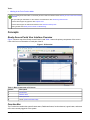
1
Ready Access Portal Help
Code No. LIT-12011342
Software Release 7.0
Issued December 5, 2014
Refer to the QuickLIT website for the most up-to-date version of this document.
Ready Access Portal Help Introduction...................................................................................4
Concepts.....................................................................................................................................5
Ready Access Portal User Interface Overview................................................................................5
Function Bar........................................................................................................................................5
License Status Indicator........................................................................................................................6
Dashboard Button.................................................................................................................................6
Function Buttons...................................................................................................................................6
Logout Button........................................................................................................................................6
Name of Current User...........................................................................................................................7
Selection Area.....................................................................................................................................7
Workspace Area..................................................................................................................................7
Workspace Title Bar..............................................................................................................................7
Workspace View...................................................................................................................................8
Ready Access Portal System Information Page..............................................................................8
Function Mode List.............................................................................................................................9
Web Browser Interaction....................................................................................................................9
Timeout..............................................................................................................................................10
Dashboard.........................................................................................................................................10
Dashboard Overview..........................................................................................................................10
Dashboard Tasks................................................................................................................................10
Dashboard Content.............................................................................................................................10
Alerts Function Mode.......................................................................................................................11
Alerts Function Mode Overview..........................................................................................................11
Alert Summary View............................................................................................................................11
Summary Function Mode.................................................................................................................12
Summary Function Mode Overview....................................................................................................12
Standard Summary View....................................................................................................................13
Device Summary View........................................................................................................................13
Tailored Summary View......................................................................................................................14
Graphic View.......................................................................................................................................15
Schedules Function Mode...............................................................................................................16
Schedules Function Mode Overview..................................................................................................16
Schedule Summary View....................................................................................................................16
Schedule Details View........................................................................................................................17
Diagnostics Function Mode.............................................................................................................19
Diagnostics Function Mode Overview.................................................................................................19
Trend Summary View..........................................................................................................................19
Trend Details View..............................................................................................................................20
Tools Function Mode........................................................................................................................21
Tools Function Mode Overview...........................................................................................................21
System Administration View................................................................................................................21
Task List....................................................................................................................................21
Working with Your Dashboard.........................................................................................................22
Viewing Your Dashboard.....................................................................................................................23
Setting a View as Your Dashboard.....................................................................................................23
Ready Access Portal Help
1
Working in the Alerts Function Mode.............................................................................................23
Viewing Alerts.....................................................................................................................................23
Filtering Alerts.....................................................................................................................................23
Acknowledging Alerts..........................................................................................................................23
Discarding Alerts.................................................................................................................................24
Working in the Summary Function Mode.......................................................................................24
Viewing a Summary of Items in the System.......................................................................................24
Viewing Details for a Device...............................................................................................................24
Viewing a Graphic...............................................................................................................................24
Changing Item Values.........................................................................................................................24
Opening the Trend Module.................................................................................................................25
Working in the Schedules Function Mode......................................................................................32
Viewing a Summary of Schedules......................................................................................................32
Viewing Details for a Specific Schedule..............................................................................................32
Adding a Temporary Override.............................................................................................................33
Deleting a Temporary Override...........................................................................................................33
Working in the Diagnostics Function Mode...................................................................................34
Viewing a Summary of Trends............................................................................................................34
Viewing Details on a Specific Trend....................................................................................................34
Working in the Tools Function Mode..............................................................................................34
Performing Other Actions................................................................................................................34
Sorting View Columns.........................................................................................................................34
Paging through a View........................................................................................................................35
Printing................................................................................................................................................35
Viewing System Information................................................................................................................35
Logging Out.........................................................................................................................................35
Ready Access Portal Troubleshooting..................................................................................36
Graphics+ Runtime Help Reference ......................................................................................42
Graphics+ Runtime Concepts..........................................................................................................42
GEL Overview.....................................................................................................................................42
Configuration Mode Versus Runtime Mode........................................................................................42
Graphics+ Auto-Refreshing.................................................................................................................43
User Actions Panel.............................................................................................................................43
Library Elements ..............................................................................................................................45
Basic Symbols.....................................................................................................................................55
Electrical..............................................................................................................................................71
Fire......................................................................................................................................................88
Floor Plan..........................................................................................................................................106
HVAC Air Coils..................................................................................................................................128
HVAC Air Sensors.............................................................................................................................136
HVAC Boilers....................................................................................................................................166
HVAC Chillers...................................................................................................................................178
HVAC Cooling Towers.......................................................................................................................186
HVAC Dampers.................................................................................................................................192
HVAC Ductwork................................................................................................................................198
HVAC Fans.......................................................................................................................................222
HVAC Heat Exchangers....................................................................................................................225
HVAC Meters....................................................................................................................................228
HVAC Pipes......................................................................................................................................234
HVAC Water Pumps..........................................................................................................................251
HVAC Water Sensors........................................................................................................................257
Help
2
HVAC Water Valves..........................................................................................................................277
Lighting..............................................................................................................................................291
Network.............................................................................................................................................297
Security.............................................................................................................................................325
Terminal Units...................................................................................................................................342
Index........................................................................................................................................348
Help
3
Ready Access Portal Help Introduction
Welcome to the Release 7.0 Ready Access Portal Help.
Click one of the following task section links to get started.
Dashboard:
•
Viewing Your Dashboard
•
Setting a View as Your Dashboard
Alerts:
•
Viewing Alerts
•
Filtering Alerts
•
Acknowledging Alerts
•
Discarding Alerts
Summary:
•
Viewing a Summary of Items in the System
•
Viewing Details for a Device
•
Viewing a Graphic
•
Opening the Trend Module
•
Changing Item Values
Schedules:
•
Viewing a Summary of Schedules
•
Viewing Details for a Specific Schedule
•
Viewing Today’s Schedule
•
Viewing Temporary Overrides
•
Viewing Scheduled Items
•
Adding a Temporary Override
•
Deleting a Temporary Override
Diagnostics:
•
Viewing a Summary of Trends
•
Viewing Details on a Specific Trend
Ready Access Portal Help
4
Tools:
•
Working in the Tools Function Mode
Do you need general information on the Ready Access Portal user interface? Start at Ready Access Portal User Interface
Overview.
Are you looking for information on other actions not listed above? See Performing Other Actions.
Curious about support for graphics? See Graphic View.
Curious about support for Tailored Summaries? See Tailored Summary View.
Having trouble? See Ready Access Portal Troubleshooting.
Concepts
Ready Access Portal User Interface Overview
Figure 1 shows a map of the Ready Access Portal UI and Table 1 names the primary components of the screen.
Click a link for more information on each part of the UI.
Figure 1: UI Overview
Table 1: Main Components of UI Screen
Callout
Description
1
Function Bar
2
Selection Area
3
Workspace Area
4
Link to System Information Page
Function Bar
The Function bar contains the system license status, Dashboard button, function buttons, Logout button, and name
of the user currently logged in to the system.
Ready Access Portal Help
5
License Status Indicator
The License Status indicator displays UNLICENSED if a piece of software on the Metasys® site is unlicensed. The
unlicensed piece of software may be the Ready Access Portal itself or an Application and Data Server/Extended
Application and Data Server (ADS/ADX) on the site. When the Ready Access Portal and all components of the
Metasys site are licensed, the unlicensed message disappears.
Dashboard Button
Dashboard button (house): Opens the Dashboard or home view.
Function Buttons
Function buttons allow you to access the function modes in which you can perform tasks. Your access privileges
determine which buttons you see and, thus, which function modes you can access. The function button for the active
function mode is highlighted in color.
Note: The function buttons do not appear for Tenant users.
Tip: If you place your cursor over a function button, the name of the function mode appears.
The function buttons are the following (left to right):
Alerts function button (bell): Opens the Alerts function mode that allows you to perform tasks related to alerts
such as acknowledging and discarding alerts. The Alerts function button flashes if unacknowledged alarms exist in
the Site Management Portal UI.
Summary function button (piece of paper): Opens the Summary function mode that allows you to perform
tasks related to summaries such as changing item values.
Schedules function button (clock): Opens the Schedules function mode that allows you to perform tasks
related to schedules such as adding temporary overrides.
Diagnostics function button (microscope): Opens the Diagnostics function mode that allows you to monitor
system performance.
Tools button (hammer and wrench): Opens the Tools function mode that allows Metasys system Administrators
to update the Ready Access Portal with changes made to the Metasys site. Refer to the Ready Access Portal
Software Installation Instructions (LIT-12011523) for information on considerations and tasks for Metasys system
Administrators.
Logout Button
The Logout button allows you to log out of the Ready Access Portal UI and return to the logon screen. When
you are finished, be sure to log out of the UI to make sure your Metasys site remains secure.
Note: Simply closing your browser window or tab does not necessarily log you out of the Ready Access Portal UI
if you have other browser windows or tabs open.
Ready Access Portal Help
6
Note: Clicking the Back button does not log you out of the Ready Access Portal UI.
See Logging Out.
Name of Current User
The name of the user currently logged on to the system appears on the Function bar just under the Logout button.
Selection Area
The Selection area contains the following:
•
•
A drop-down list box that contains all user views present in the Site Director that have been assigned to you
(currently logged on user).
A selection tree that represents the folder structure of the user view you select in the drop-down list box. The
folder you select in the selection tree sets the context for what appears in the Workspace area.
Note: All user views visible in the Ready Access Portal UI are the same user views present in the Site Director.
(User Views are assigned per user; therefore, the user view visible in the Ready Access Portal UI is the same
user view present in the Site Director for each specific user.)
The Selection area appears in the Alerts, Summary, Schedules, and Diagnostics function modes. The Selection
area also allows you to select graphics and folders that are present in the user view.
Note: The Selection area does not appear in the Tools function mode or in the Dashboard.
The twin arrows on the side of the Selection area allow you to expand or collapse the Selection area and increase
or decrease the area available for the Workspace area.
Workspace Area
The Workspace area contains different views depending on the function mode you select, the task you are performing,
and the item you select in the Selection area (if present).
The Workspace area has the following sections:
•
•
title bar
view
Workspace Title Bar
The Workspace title bar contains the name of the view and the context of the view; for example, the name of the
folder you select in the selection tree or the name of a graphic.
The Workspace title bar also may contain the buttons in Table 2.
Ready Access Portal Help
7
Table 2: Workspace Title Bar Buttons
1
Description
Button
Set as Dashboard
House and Arrow
Sets the currently displayed view as the Dashboard. The Dashboard appears when you:
•
click the Dashboard button
•
log in to the system (the default view)
For Metasys system Standard Access administrators, this button allows you set the
Dashboard for yourself or other system users. This button does not appear for Tenant
users.
Help
Question Mark
Displays this Help system in a separate window or tab, depending on your browser settings.
Filter
Building and Folder
or
Appears in the Alert Summary view only. This button allows you to change the context of
the alerts visible in the Alert Summary view. When you click this button, the context of the
Alert Summary view toggles between the entire site (unfiltered) and the entire contents of
the folder currently selected (filtered). The Filter button appears as a building icon when
the view is unfiltered and as a folder icon when the view is filtered. If you do not select a
folder in the selection tree, the Filter button is disabled.
1
The Refresh and Back buttons no longer appear in the Workspace title bar. Use the web browser buttons instead. See Web
Browser Interaction.
Workspace View
Each function mode supports one or more Workspace views. For more information on the views available in each
function mode, see Function Mode List.
For more information on tasks you can perform in the Workspace views, see Task List.
Ready Access Portal System Information Page
The System Information link appears at the bottom-right corner of the Ready Access Portal UI screen. When you
click this link, the following system information appears in a new browser window:
•
•
•
•
•
Ready Access Portal software version
Metasys Graphics Package software version (that is, the version of the Metasys Graphics Package currently
installed on the Ready Access Portal Server)
system color key for statuses
system color key for alert levels (priority range)
copyright information
The system color keys reflect the color assignments defined by Metasys system preferences. Status colors are used
in the Standard Summary view, Tailored Summary view, and Graphic view to indicate the status of an item (for
example, alarm, overridden, or offline).
Alert level colors are used in the Alert Summary view to indicate the priority level of an alert. A priority level
encompasses a particular set of alert priorities and reflects the relative severity or importance of the alert. Alert
priorities range from 1 (highest priority/importance) to 255 (lowest severity/importance).
Ready Access Portal Help
8
For information on the system alert and status colors defined, refer to the Preferences section of the Metasys® SMP
Help (LIT-1201793).
Function Mode List
The Dashboard displays a view from one of the function modes.
The following function modes allow you to perform specific tasks in the Ready Access Portal UI:
•
Alerts Function Mode
•
Summary Function Mode
•
Schedules Function Mode
•
Diagnostics Function Mode
•
Tools Function Mode
Web Browser Interaction
The Ready Access Portal UI uses select web browser features in the following ways:
•
•
•
Text Size: The Ready Access Portal UI responds to changes you make for the web browser text size.
Favorites: You can bookmark the Ready Access Portal UI, the login address, and specific views within the UI.
Full Screen: The F11 key allows you to view the Ready Access Portal UI without the web browser framework
(Full Screen view). We recommend you view the Ready Access Portal UI in Full Screen view to maximize room
available for Ready Access Portal UI content.
Keep in mind that if you use Full Screen view, you do not have access to the web browser Back, Forward, Refresh,
and other buttons. As an alternative, you can use key strokes or the mouse right-click menu to navigate.
Navigation/Menus: When you are logged in to the Ready Access Portal UI, use care when using Windows® Internet
Explorer® web browser buttons and menus.
Back (or Backspace key): Returns you to the previous address. If you navigate from the Ready Access Portal UI
to another address while you are logged in, you can click the Back button to return to the UI. Navigating to another
address does not log you out of the Ready Access Portal UI. If you use the Back button to log in multiple users,
devices in your Metasys system may reset.
Forward: Allows you to move forward in the browsing history. If you use the Back button, you can use the Forward
button to return to the next address that you accessed.
Refresh: Refreshes the values that appear in the current view.
The Ready Access Portal UI refreshes automatically every 5 to 15 seconds. If a problem exists with the automatic
refresh, an orange triangle with an exclamation point appears next to the Logout button. For more information, see
Ready Access Portal Troubleshooting.
Home: If you click Home, your designated Home page appears. You are not logged out of the Ready Access Portal
UI.
Favorites: You can bookmark the address for the Ready Access Portal UI, the login address, and specific views
within the UI. If you are not logged in, and you click a Ready Access Portal UI bookmark, the login screen appears.
New Windows: If you want to run more than one Ready Access Portal UI window, open a new window from the
Start menu or double-click the Internet Explorer web browser icon. Do not create a window using the File > New
Window selection, File > New > Tab selection, or the Ctrl-N shortcut.
Ready Access Portal Help
9
Timeout
The Ready Access Portal UI supports the Never Terminate setting of a user profile in the Site Management Portal
UI Security Administrator System. If a user is configured to never time out, and the user logs on to the Ready Access
Portal UI, the user is never logged off due to inactivity.
Note: The handheld Ready Access Portal UI does not support this functionality.
Note: Users that are configured to never time out still are logged off from the system if the Metasys system
Administrator initiates an update or if the computer running the Ready Access Portal software restarts.
Dashboard
Dashboard Overview
The Dashboard is your home view and appears when you click the Dashboard button (if present) and appears as
the default when you first log on. The view set as your Dashboard can be the following views from the Alerts,
Summary, Schedules, or Diagnostics function modes:
•
Alarm Summary view
•
Standard Summary view
•
Device Summary view
•
Tailored Summary view
•
Graphic view
•
Schedule Summary view
•
Schedule Details view
•
Trend Summary view
•
Trend Details view
If you are a Tenant user, you can access only the view that appears as the Dashboard and any views you can access
via a link in the Dashboard.
Dashboard Tasks
The following task section applies to the Dashboard:
Setting a View as Your Dashboard
Note: Tenant users cannot set a view as their Dashboard. Tenant users should contact the Metasys system Standard
Access Administrator to set a view as their Dashboard.
Note: See the Task List section for tasks associated with views that can be set as the Dashboard.
Dashboard Content
The Dashboard displays the view you (or your Metasys system Standard Access Administrator) set using the Set
as Dashboard button.
Until you set which view appears as the Dashboard, a message appears indicating that your dashboard is not defined.
If this happens, Tenant users should contact their Metasys system Standard Access Administrator to have their
Dashboard set.
Tip: The Dashboard function mode does not have a Selection area.
Ready Access Portal Help
10
Consider the following behavior when you click the Set as Dashboard button:
•
The specific view in place when you click the Set as Dashboard button is the view that appears as the Dashboard.
Example
•
•
If a Device Summary view is visible when you click the Set as Dashboard button, the Device Summary is the
view that appears as the Dashboard (as opposed to the Standard Summary view, which is the default view for
the Summary function mode).
If a view set as the Dashboard has links or navigation, these links and navigation continue working in the
Dashboard, but the view set as the Dashboard does not change.
Example
•
•
•
If you have a Standard Summary view as your Dashboard, and you click a device link, the Device Summary
view for that device appears in the Dashboard. The next time you click the Dashboard button, the Standard
Summary view appears.
If you sort the view information before you click the Set as Dashboard button, the view that appears as the
Dashboard retains the sort.
If you are viewing the Dashboard, and navigate to another view through your Dashboard, you can click the Set
as Dashboard button in the new view. The Dashboard updates to display the new view. Tenant users do not
have this capability.
Alerts Function Mode
Alerts Function Mode Overview
The Alerts function mode allows you to detect and manage alerts for your system. If you have the required privileges,
you can acknowledge and discard alerts.
What is an alert?
An alert is a system alarm/event that the currently logged on user has the access privileges to acknowledge.
The Alerts function mode contains the following view:
•
Alert Summary view
Alert Summary View
The Alert Summary view is the only view available for the Alerts function mode. The Alert Summary view displays
the top 100 (newest, highest priority) pending alerts that you have the access privileges to acknowledge. By default,
alerts are limited to the previous 5 days and appear in the context of the entire site (unfiltered).
You also can filter the Alert Summary view by selecting a folder in the selection tree and clicking the Filter button
(see Workspace Title Bar buttons). When filtered, the Alert Summary view displays the top 100 pending alerts for
the items contained in the folder you selected in the selection tree. If you click a new folder in the selection tree while
the Alert Summary view is filtered, the view displays alerts in the context of the new folder. If you click the Filter
button to remove the filter, the view once again displays alerts in the context of the entire site and the folder selected
in the selection tree does not impact the view. Items displayed in the Ready Access Portal UI use color to indicate
the state of alerts and overrides. See Ready Access Portal System Information Page for details.
The user view folders are used to filter the Alert Summary function based on a parent/child relationship. For example,
a site with five NAEs may have a user view that contains each NAE device without any other points or devices added
under each NAE. When you select one of the individual NAEs as the filter from the user view, any child devices or
points of that NAE are the points shown in the Alert Summary view.
Ready Access Portal Help
11
Alert Summary View Tasks
The following task sections apply to the Alert Summary view:
•
Viewing Alerts
•
Filtering Alerts
•
Acknowledging Alerts
•
Discarding Alerts
Alert Summary View Content
The Workspace title bar displays the name of the Site Director as the context of the view.
See Alert Summary View Content for details on the Alert Summary view.
Table 3: Alert Summary View Content
Column
Details
Icon
Displays a blue star (
) if the alert is new as defined by the Site Management Portal UI preferences.
By default, this value is new alerts from the past 15 minutes. For information on changing the interval
to another value from 5 to 60 minutes, refer to the Metasys® SMP Help (LIT-1201793).
Note:
This column does not have a name. Look for the column on the left with pictures.
Type
Displays the alert type; for example, High Alarm, Low Alarm, Normal.
Priority
Shows the alert priority. The background color of each alert corresponds to the priority value of the
alert as defined by Metasys system preferences.
Time
Lists the date and time the system issued the alert.
Item
Displays the name of the object (from the Name attribute) that generated the alert. When an item
resides in a field device, and the user is authorized to view details for the field device, an icon appears
(
) linking you to the Device Summary view for the device.
Value
Lists the value of the attribute causing the alert.
Message
Displays any message text associated with the alert.
Acknowledge
Allows you to acknowledge the alert and remove it from the list of alerts. When you acknowledge
an alert here, you also acknowledge the alert according to the Site Management Portal UI.
Note:
Discard
This column does not have a name. Look for the column second from the right with check
marks.
Allows you to discard the alert. When you discard an alert here, you also acknowledge and discard
the alert according to the Site Management Portal UI. This means that the alert disappears from the
Site Management Portal UI but not the alarm database.
You can discard alerts only if you have the appropriate privileges.
Note:
This column does not have a name. Look for the column on the right with garbage can icons.
Summary Function Mode
Summary Function Mode Overview
The Summary function mode provides summary information and graphics that allow you to monitor and manage
the site.
Ready Access Portal Help
12
The Summary function mode contains the following views:
•
Standard Summary view
•
Device Summary view
•
Tailored Summary view
•
Graphic view
Standard Summary View
The Standard Summary view contains information on objects directly inside the folder you select in the selection
tree. If you click a link in the Value column and you have the appropriate privileges, you can change the value of
the object. Items displayed in the Ready Access Portal UI use color to indicate the state of alerts and overrides. See
Ready Access Portal System Information Page for details.
Standard Summary View Tasks
The following task sections apply to the Standard Summary view:
•
Viewing Details for a Device
•
Changing Item Values
Standard Summary View Content
The Workspace title bar displays the name of the folder you select in the selection tree as the context of the view.
See Table 4 for details on the Standard Summary view.
Table 4: Standard Summary View Content
Column
Details
Icon
Shows a picture corresponding to the type of item. The icons match icons used in the Site
Management Portal UI.
Note:
Item
This column does not have a name. Look for the column on the left with pictures.
Displays the name of the item.
If you are authorized, the name may be a link to the Device Summary view for the item.
Value
Lists the value of the item.
If you are authorized, the value may be a link that allows you to change the value. See Changing
Item Values.
The background color of this cell corresponds to the status of the item as defined by Metasys
system preferences.
Status
Lists the status of the item. If the status is normal, this column is blank.
Device Summary View
The Device Summary view contains information on all field points that belong to the field device that you selected
in the Standard Summary view. If you click a link in the Value column and you have the appropriate privileges, you
can change the value of the field point item.
Ready Access Portal Help
13
Device Summary View Tasks
The following task section applies to the Device Summary view:
•
Changing Item Values
Device Summary View Content
The Workspace title bar displays the name of the device you selected in the Standard Summary view as the context
of the view.
See Table 5 for details on the Device Summary view.
Table 5: Device Summary View Content
Column
Details
Icon
Shows a picture corresponding to the type of item. The icons match icons used in the Site
Management Portal UI.
Note:
This column does not have a name. Look for the column on the left with pictures.
Item
Displays the name of the item.
Value
Lists the value of the item. If you are authorized, the value may be a link that allows you to change
the value. See Changing Item Values.
The background color of this cell corresponds to the status of the item as defined by Metasys
system preferences.
Status
Lists the status of the item. If the status is normal, this column is blank.
Path
Displays the folder in which the item resides under the device. If the item does not reside in a
folder within the device (that is, it simply resides directly under the device), this cell is blank.
Tailored Summary View
The Ready Access Portal UI Summary function mode supports Tailored Summaries. When you view a folder in the
selection tree that has Tailored Summaries associated with it, the default view (either a Tailored Summary view or
the Standard Summary view) appears in the Workspace. The Workspace title bar shows the name of the Tailored
Summary or Standard Summary, followed by the name of the folder selected in the selection tree. If you click the
right-facing arrow to the left of the Tailored Summary or Standard Summary name, you can select between viewing
the available Tailored Summaries or viewing the Standard Summary. See Standard Summary View.
When you display a Tailored Summary, the columns and key data appear. You cannot rearrange the columns, but
you can sort them by clicking a column title. Any graphics linked to the Tailored Summary are available in the Ready
Access Portal UI, subject to requirements in the Graphic View section. If you click a link to a device in the Tailored
Summary view, the Device Summary view for that device appears. See Device Summary View. You also can change
the value of an item by clicking a value link. Tailored Summaries use the same color preferences for alerts and
overrides as those used in the Site Management Portal UI. See Ready Access Portal System Information Page for
details.
For information on Tailored Summaries, refer to the Metasys® SMP Help (LIT-1201793).
Tailored Summary View Tasks
The following task sections apply to the Tailored Summary view:
•
Viewing a Summary of Items in the System
•
Viewing Details for a Device
•
Viewing a Graphic
Ready Access Portal Help
14
•
Changing Item Values
•
Adding a Temporary Override
Graphic View
Graphics appear in the user view tree as stand-alone items with a graphic symbol next to them (
for User Graphics
Tool [UGT] graphics, and
for Graphics Plus graphics) and in Tailored Summaries using the same symbols. See
Tailored Summary View for details on Tailored Summaries in the Ready Access Portal UI. The Workspace title bar
shows the word Graphics and then the name of the graphic, separated by a colon.
Graphics displayed in the Ready Access Portal UI use color to indicate the state of alerts and overrides. See Ready
Access Portal System Information Page for details. If you add new graphics in the Site Management Portal UI, you
must perform a synch. You can change point values using graphics in the Ready Access Portal UI.
You also can add temporary overrides from a graphic when the symbol in the graphic is bound to a schedule.
And lastly, you can view trend information for an object from a Graphics+ graphic if trend data exists for the object.
For details, see Opening the Trend Module.
Keep the following in mind when using graphics in the Ready Access Portal UI:
•
•
You can display graphics while in the Summary function mode only.
You must have Microsoft® Silverlight™ plug-in to view graphics. If you do not have the Silverlight plug-in installed,
you are prompted to do so the first time you view a graphic. For additional installation instructions, refer to the
Ready Access Portal Software Installation Instructions (LIT-12011523).
The Display Control tool allows you to zoom and pan a graphic displayed in the Ready Access Portal UI. See Figure
2 and Table 6 for details on the Display Control tool.
Figure 2: Display Control Tool
Ready Access Portal Help
15
Table 6: Components of Display Control Tool
Callout
Name
Description
1
Collapse
Hides the Display Control tool. After you hide the tool, a faint arrow
appears that allows you to restore the tool.
2
Fit to Window
Zooms the graphic to fit in the frame.
(center block)
3
Zoom Ball with Zoom Ring
Allows you to zoom by moving the ball clockwise (zoom in) and
counterclockwise (zoom out) along the zoom ring.
4
Turn On/Off Panning
Enables and disables the panning tool that allows you to move the
graphic in the workspace.
5
Move (four arrows)
Allows you to pan up, down, left, and right over the graphic in set
increments.
6
Current Zoom Level
Displays the current zoom level.
7
Turn On/Off Zoom Mode
Enables and disables the manual zoom (magnifying glass) that allows
you to re-center the graphic and zoom in an out.
8
Tools Menu
Drops down a list of Tools. At this time, only the Trend Module is
available.
9
Trend
Opens and closes the Trend Module. This option appears when you
click the Tools down arrow. See Opening the Trend Module.
10
Move Display Control
Allows you to move the Display Control tool to a different area of the
graphic.
Graphic View Tasks
The following task sections apply to the Graphic view:
•
Viewing a Graphic
•
Opening the Trend Module
•
Changing Item Values
•
Adding a Temporary Override
Schedules Function Mode
Schedules Function Mode Overview
The Schedules function mode allows you to see schedule information for the site.
The Schedules function mode contains the following views:
•
Schedule Summary view
•
Schedule Details view
Schedule Summary View
The Schedule Summary view contains a list of the schedules present in the folder you select in the selection tree
and any nested folders under that folder. If you click a link in the Value column and you have the appropriate privileges,
you can add a temporary override.
What is a temporary override?
A temporary override is a short term change you make to the output value of a schedule.
Ready Access Portal Help
16
Schedule Summary View Tasks
The following task sections apply to the Schedule Summary view:
•
Viewing Details for a Specific Schedule
•
Adding a Temporary Override
Schedule Summary View Content
The Workspace title bar displays the name of the folder you selected in the selection tree as the context of the view.
See Table 7 for details on the Schedule Summary view.
Table 7: Schedule Summary View Content
Column
Details
Icon
Shows a picture corresponding to a schedule.
Note:
This column does not have a name. Look for the column on the left with pictures.
Item
Displays the name of the Schedule object. If you are authorized, a link appears to the Schedule
Details view for the object.
Value
Contains the output value of the schedule. If you are authorized and the schedule supports temporary
overrides, the value may be a link that allows you to temporarily override the schedule. See Adding
a Temporary Override. The background color of this cell corresponds to the status of the item as
defined by Metasys system preferences.
Status
Lists the status of the item. If the status is normal, this column is blank.
Path
Displays the folder in which the schedule resides within the folder you select in the selection tree.
If the schedule does not reside in a folder (that is, it simply resides directly under the folder you
selected in the selection tree), this cell is blank.
Schedule Details View
The Schedule Details view contains details on the schedule you selected in the Schedule Summary view.
The Schedule Details view contains the following tabs:
•
Today's Schedule tab
•
Temporary Overrides tab
•
Scheduled Items List tab
Schedule Details View Tasks
The following tasks apply to the Schedule Details view:
•
Adding a Temporary Override
•
Deleting a Temporary Override
Schedule Details View Content
The Workspace title bar displays the name of the item you selected in the Schedule Summary view as the context
of the view.
Under the Workspace title bar, the Schedule Details view lists the current day, the schedule’s current output value,
and the schedule’s status.
Ready Access Portal Help
17
Times in the Schedules function mode display in 24-hour time format. For example:
•
•
•
00:00 is the start of the day
24:00 is the end of the day
12:00 is noon
Note: See Ready Access Portal Troubleshooting if you would like to change the time format to 12-hour time.
Note: For Release 6.0 or later, the display of Alerts, Schedules, and Trend Details includes the time zone.
Today’s Schedule Tab
The Today’s Schedule tab contains changes to the schedule for the current day, ending at 24:00.
Example
For example, if the schedule changes to On at 08:32 and Off at 13:54, only those entries exist in the Today’s
Schedule tab.
Note: If the schedule does not implement the Today’s Schedule feature, text indicating this lack of functionality
appears at the bottom of the Today’s Schedule tab.
See Table 8 for details on the Today’s Schedule tab.
Table 8: Today’s Schedule Tab Content
Column
Description
Time
Displays the local time for the scheduled event in hours:minutes using 24-hour format.
This time applies to the current day only.
Note:
Value
For Release 6.0 or later, the display of Alerts, Schedules, and Trend Details includes
the time zone.
Lists the projected output value of the schedule.
Temporary Overrides Tab
The Temporary Overrides tab contains a list of temporary overrides currently defined for the schedule you selected.
If you click the Add Temporary Override link, and you have the appropriate privileges, you can add a temporary
override.
Note: If the schedule does not support the temporary override feature, text indicating that lack of functionality
appears at the bottom of the Temporary Overrides tab.
See Table 9 for details on the Temporary Overrides tab.
Table 9: Temporary Overrides Tab Content
Link/Column
Description
Add Temporary Override
If you are authorized, this link allows you to create a new temporary override for the
schedule you are viewing. Temporary overrides apply to the current day, up to 24:00. See
Adding a Temporary Override.
Starts On
Shows the date for the start of the override.
Ends On
Shows the date for the end of the override.
Daily Start
Shows the hour and minute of the day for the start of the override. This time is in terms
of the days in the Starts On and Ends On fields. For the start of the day, select 00 for the
Hour and 00 for the Minute.
Ready Access Portal Help
18
Table 9: Temporary Overrides Tab Content
Link/Column
Description
Daily End
Shows the hour and minute of the day for the end of the override. This time is in terms of
the days in the Starts On and Ends On fields. For the end of the day, select 24 for the
Hour and 00 for the Minute.
Value
Lists the output value of the schedule during the override.
Delete Temporary Override
Allows you to delete the temporary override.
Note:
This column does not have a name. Look for the column on the right with garbage
can icons.
Scheduled Items List Tab
The Scheduled Items List tab contains a list of objects controlled by the schedule you selected.
See Table 10 for details on the Scheduled Items List tab.
Table 10: Scheduled Items List Tab Content
Column
Description
Icon
Shows an icon indicating the item type.
Note:
This column does not have a name. Look for the column on the left with pictures.
Item
Displays the name of the scheduled item.
Attribute
Displays the name of the scheduled attribute.
Value
Lists the value of the scheduled item’s scheduled attribute. The background color of this cell
corresponds to the status of the scheduled item. For assistance on the meaning of the color,
contact your Metasys system Administrator.
Status
Lists the status of the scheduled item. If the status is normal, this column is blank.
Priority
Shows the priority controlling the value of the scheduled item’s attribute.
Diagnostics Function Mode
Diagnostics Function Mode Overview
The Diagnostics function mode allows you to view trend information to monitor and evaluate the performance of the
Metasys system.
The Diagnostics function mode contains the following views:
•
Trend Summary view
•
Trend Details view
Trend Summary View
The Trend Summary view contains a list of trends (extensions) for the items in the folder you select in the selection
tree and all items in folders nested under the folder you select.
Ready Access Portal Help
19
Trend Summary View Tasks
The following task section applies to the Trend Summary view:
•
Viewing Details on a Specific Trend
Trend Summary View Content
The Workspace title bar displays the name of the folder you select in the selection tree as the context of the view.
See Table 11 for details on the Trend Summary view.
Table 11: Trend Summary View Content
Column
Details
Icon
Shows a picture corresponding to the type of object that has a trended attribute. The icons match
the icons used in the Site Management Portal UI.
Note:
This column does not have a name. Look for the column on the left with pictures.
Item
Displays the name of the trended item.
Status
Lists the status of the trended item. If the status is normal, this column is blank.
Trend
Lists the name of the Trend extension. If you are authorized, a link appears to the Trend Details
view for the Trend extension.
Trend Status
Lists the status of the Trend extension. If the status is normal, this column is blank.
Path
If the folder you select in the selection tree (Folder A) contains another folder (Folder B) with a
trended item inside it, this column displays the name of the trended item’s folder (Folder B).
If the trended item does not reside in a folder (that is, it simply resides directly under the item you
select in the selection tree), this cell is blank.
Trend Details View
The Trend Details view contains a table of data samples for the specific trend extension you selected in the Trend
Summary view.
Trend Details View Tasks
No tasks apply to the Trend Details view at this release.
Trend Details View Content
The Workspace title bar displays the name of the item you selected in the Trend Summary view as the context of
the view.
The Format button allows you to toggle the Trend Details view between table and chart format. This button appears
as a chart icon ( ) when you are in table view and as a table icon ( ) when you are in chart view (default view
format).
The Time Frame (Hours) links allow you to change the time frame (in hours) for viewing the trend’s data samples.
Options are 1, 12, 24, 48, and 72 hours. The default time frame is 12 hours.
The chart format of the Trend Details view shows a line chart tracing the value of the trend extension you selected
in the Trend Summary view. If you place your cursor over a point on the line, the value of the trended data sample
appears in a tool tip window.
The tabular format of the Trend Details view shows the value of the trend extension over time using a table with one
sortable column. See Table 12 for details on the Trend Details view (tabular format).
Ready Access Portal Help
20
Table 12: Trend Details View Content (Tabular Format)
Column
Details
Time
Displays the date and time that the trend collected the data sample. This column
is sortable.
Value
Displays the data sample value.
Tools Function Mode
Tools Function Mode Overview
The Tools function mode is accessible only by users with Metasys system Administrator access rights.
The Tools function mode contains the following view:
•
System Administration view
System Administration View
The System Administration view allows Metasys system Administrators to update the Ready Access Portal UI content
after making the following changes to the Metasys site:
•
•
•
•
•
Add, remove, or modify user views.
Add or remove trends extensions.
Add or remove field points.
Change bindings in User Graphics Tool [UGT] graphics.
Discover BACnet third-party devices or objects whose states text does not match an existing Johnson Controls®
standard set, resulting in the creation of a new user-defined enumeration set.
These changes do not appear in the Ready Access Portal UI until a Metasys system Administrator performs an
update. If you make any of these changes on an engine, issue an Archive command for the Engine object before
you update the Ready Access Portal UI.
When a Metasys system Administrator clicks the Update button, the Ready Access Portal logs him/her out of the
system immediately. All other users return to the log on page with their next click. You must log back on when the
update is complete.
System Administration View Tasks
Working in the Tools Function Mode
Refer to the Ready Access Portal Software Installation Instructions (LIT-12011523) for information on considerations
and tasks for Metasys system Standard Access Administrators.
System Administration View Content
Refer to the Ready Access Portal Software Installation Instructions (LIT-12011523) for information on considerations
and content for Metasys system Standard Access Administrators.
Task List
Click one of the following task sections for details:
Ready Access Portal Help
21
Dashboard:
•
Viewing Your Dashboard
•
Setting a View as Your Dashboard
Alerts:
•
Viewing Alerts
•
Filtering Alerts
•
Acknowledging Alerts
•
Discarding Alerts
Summary:
•
Viewing a Summary of Items in the System
•
Viewing Details for a Device
•
Viewing a Graphic
•
Changing Item Values
Schedules:
•
Viewing a Summary of Schedules
•
Viewing Details for a Specific Schedule
•
Viewing Today’s Schedule
•
Viewing Temporary Overrides
•
Viewing Scheduled Items
•
Adding a Temporary Override
•
Deleting a Temporary Override
Diagnostics:
•
Viewing a Summary of Trends
•
Viewing Details on a Specific Trend
Tools:
•
Working in the Tools Function Mode
Other actions you can take:
•
Sorting View Columns
•
Paging through a View
•
Printing
•
Printing Content from the Ready Access Portal UI
•
Printing the Help
•
Viewing System Information
•
Logging Out
For general Ready Access Portal UI information, see the Ready Access Portal User Interface Overview section.
Working with Your Dashboard
This section contains the following task sections related to the Dashboard:
•
Viewing Your Dashboard
•
Setting a View as Your Dashboard
Ready Access Portal Help
22
Viewing Your Dashboard
To view your Dashboard, click the Dashboard button in the Function bar.
Setting a View as Your Dashboard
This task does not apply to Tenant users. A Metasys system Standard Access Administrator must set the Dashboard
for a Tenant user.
When a view is set as your Dashboard, the view appears as the default view when you log on and when you click
the Dashboard function button (if present). If you have a view defined as the Dashboard already, this procedure
allows you to update the view with a new sort order or other changes.
To set a view as your Dashboard:
1. Select a function mode button in the Function bar.
2. Open the view you would like as your Dashboard.
3. Click the Set as Dashboard button (
).
Note: For Metasys system Standard Access administrators, this button allows you to set the Dashboard for
yourself or other system users. This button does not appear for Tenant users.
Working in the Alerts Function Mode
This section contains the following task sections related to the Alerts function mode:
•
Viewing Alerts
•
Filtering Alerts
•
Acknowledging Alerts
•
Discarding Alerts
Viewing Alerts
To view alerts, click the Alerts function mode button in the Function bar.
Filtering Alerts
To filter alerts:
1. Click the Alerts function mode button in the Function bar.
2. Select a folder in the selection tree.
Note: If you do not select a folder in the selection tree, the filter button is disabled.
3. In the Workspace title bar, click the Filter button so that it appears as a folder (
the Filter button.
). See Table 2 for details on
The view updates to display the top 100 alerts for the all items contained in the folder you selected in Step 2.
This filter includes items directly under the folder and any child items.
4. To remove the filter, click the Filter button until it appears as a building (
).
The view updates to display the top 100 alerts for the entire site.
Acknowledging Alerts
To acknowledge alerts:
1. Click the Alerts function mode button in the Function bar.
2. Find the row for the alert you would like to acknowledge.
Ready Access Portal Help
23
3. Click the check mark icon for that row (
).
4. The view updates to remove the acknowledged alert.
Discarding Alerts
To discard alerts:
1. Click the Alerts function mode button in the Function bar.
2. Find the row for the alert you would like to discard.
3. Click the garbage can icon for that row (
).
4. The view updates to remove the discarded alert.
Working in the Summary Function Mode
See the following task sections related to the Summary function mode:
•
Viewing a Summary of Items in the System
•
Viewing Details for a Device
•
Viewing a Graphic
•
Changing Item Values
Viewing a Summary of Items in the System
To view a summary of items in the system:
1. Click the Summary function mode button in the Function bar.
2. Select a user navigation tree from the Selection area drop-down list box.
3. In the selection tree, browse to the folder you want to view. The Standard Summary view or Tailored Summary
view appears in the Workspace area.
Note: If you click the right-facing arrow to the left of the Tailored Summary or Standard Summary name in the
Workspace title bar, you can select between viewing the available Tailored Summaries or viewing the
Standard Summary.
Viewing Details for a Device
To view details for a device:
1. Follow the steps in Viewing a Summary of Items in the System to display the Standard Summary view.
2. In the Item column of the Standard Summary view, click a link for the device you would like to view. If you are
viewing a Tailored Summary, click a link in a row or in the key data. The Device Summary view appears.
Viewing a Graphic
To view a graphic, click a graphic item in the Selection area or click the graphic icon for an item in the Standard
Summary view or Tailored Summary view. The Graphic view appears.
Use the Display Control tool to zoom and pan the graphic. See the Graphic view for information on this tool.
For information on how to view trend information for an object that appears on a Graphics+ graphic, see Opening
the Trend Module.
Changing Item Values
Note: You must have the appropriate privileges to change item values.
To change item values from a summary:
Ready Access Portal Help
24
1. In the Summary function mode, do one of the following:
•
In the Standard Summary view, click a link in the Value column; this allows you to change the value of the
item you clicked.
•
In the Device Summary view, click a link in the Value column; this allows you to change the value of the item
you clicked.
•
In the Tailored Summary view, click a link in a column; this allows you to change the value of the item you
clicked.
•
In the Graphic view, click a selectable item; this allows you to change the value of the item you clicked.
The Change Value dialog box appears and allows you to change the current value of an item. Table 13
describes the content of the dialog box.
2. Use Table 13 to complete the Change Value dialog box.
Table 13: Change Value Dialog Box
Item
Description
Instructions Text
Contains instructions for using the Change Value dialog box. The instructions appear
at the top of the dialog box.
Item Name Text
Contains the name of the item for which you are submitting a value change. The item
name appears in the box grouping the Type and Value fields.
Type Field
Allows you to select the type of change:
•
Set Value: Changes the current value until another process assumes control.
•
Hold Value: Maintains the value until another process assumes control.
•
Remove Hold: Removes the hold on the value.
Value Field
For Set Value and Hold Value types, allows you to select or enter a value in this field.
Description of Change Type Text
Describes the type of change you selected in the Type field. The change type
description appears just above the Submit and Cancel buttons.
Submit Button
Submits the change.
Cancel Button
Cancels the change.
3. When you are finished, click Submit. The item value changes to the value you specified.
When you submit a value change, a refresh request issues after a short delay. If the item receives the change
value request prior to the refresh being executed, the updated value appears in the view. If the refresh executes
prior to the item receiving the change value request, then the new value does not appear immediately and a
manual refresh is required to update the value shown on the screen immediately. The Ready Access Portal
refreshes automatically every 5 to 15 seconds. See Workspace Title Bar for information on the Refresh button.
Opening the Trend Module
To open the Trend Module for an object on a Graphics+ graphic, click View Trend from the element’s User Actions
Panel (Figure 3). The Trend Module appears with the charted trend data (Figure 4). If more than one trended attribute
is available, click View Trend to display a submenu that lists all available trended attributes. Click a trended attribute
to open the Trend Module.
Ready Access Portal Help
25
Figure 3: Selecting a Trend to Add to the Trend Module
If you want to open the Trend Module without adding or changing its content, click the Tools drop-down arrow on
the Graphics+ Display Control tool (Figure 2) and select Trend. The Trend Module reappears in its last state and
condition.
For more details, see Trend Module Chart Functions and Trend Module Legend Functions.
Trend Module Chart Functions
See Figure 4 and Table 14 for explanations of the Trend Module chart components.
Ready Access Portal Help
26
Figure 4: Graphics+ Trend Module - Chart Functions
Table 14: Descriptions of Trend Module Chart Components
Number
Name
Description
1
Plot Area
Plots the trend data for all objects added to the Trend Module.
2
Box Zoom
Zooms in for the area that is highlighted. To enable box zoom, place
the cursor inside the plot area, hold down the mouse and drag left or
right. A white shadow appears to outline the zoom area.
3
Callouts
Indicates the name of the trended object with its value at the selected
moment in time (white vertical line).
4
Maximize
Changes the size of the Trend Module to its maximum size within the
constraints of the Metasys display panel.
5
Close
Removes the Trend Module from the screen.
6
Zoom Out
Returns the chart to its original size. This option is only available if the
chart is currently zoomed in.
Ready Access Portal Help
27
Table 14: Descriptions of Trend Module Chart Components
Number
Name
Description
7
Right Y Axis
(state data)
Indicates the axis that is plotting the discrete states for objects currently
displayed in the Trend Module. Metasys objects that are displayed on
this axis typically consist of Boolean or multi-state values.
8
Right Pan Arrow
Shifts the chart to display more recent trend data.
9
Newest Date/Time
Displays date and time of the last value that appears on the chart.
10
Moment in Time
(X Axis)
Indicates the date and time of the value at a particular location on the
chart. The date/time information as well as a vertical moment in time
line is displayed as you move the mouse over the chart. The units
along the x-axis always represent time.
11
Oldest Date/Time
Indicates the date and time of first sample that appears on the chart.
12
Left Pan Arrow
Shifts the chart to display older trend data.
13
Left Y Axis
Indicates the axis that is plotting the numeric values for objects
currently displayed in the Trend Module. Metasys objects that are
displayed using this axis typically consist of analog values.
(numeric)
14
Scroll Bar
Adjusts the range of data that appears on the chart. Also zooms in
and out when you resize the scroll bar. To zoom, click and drag the
left/right arrows of the scroll bar. To pan, drag the scroll bar left or
right.
15
Refresh
Updates the trend data for all objects shown in the Trend Module.
Trend Module Legend Functions
See Figure 5 and Table 15 for explanations of the Trend Module legend components.
Ready Access Portal Help
28
Figure 5: Graphics+ Trend Module - Legend Functions
Table 15: Descriptions of Trend Module Legend Components
Number
Name
Description
1
Legend Splitter Bar
Resizes the space taken by the legend. Move the splitter to the bottom
or double-click the splitter bar to hide the legend and increase the size of
the trend chart.
2
Legend Icons
Display both the color and the y-axis that is used to display the trend data
for the trended object in this row of the legend. The legend color assigned
to an object matches its trended values in the chart, so that you can
correlate information between the legend and the chart.
Four preset trend line colors are used: blue, orange, violet, and white.
The colors cannot be customized. These icons are used:
The forward facing L indicates that the left y-axis is used for this trend
series, which displays numeric values.
The backward facing L indicates that the right y-axis is used for this
trend series, which displays state values.
Ready Access Portal Help
29
Table 15: Descriptions of Trend Module Legend Components
Number
Name
Description
3
Show/Hide Trend
Selects which objects currently appear in the chart. Click this box to hide
and unhide trend data.
4
Object Name
Displays the name for the trended Metasys object. When you click the
object name (or its row), the corresponding line in the chart is highlighted.
5
Trend Name
Displays the name of the trend that appears in the chart. If more than one
trend is available for this trended object, a drop-down box appears from
which to select.
6
Navigate
Navigates away from the Trend Module and the graphic and opens the
trend data for the attribute. If you are not authorized to view the object,
the navigate button is disabled.
7
Remove
Removes the trended object and its associated data from the Trend
Module.
The Trend Module has the following characteristics:
Loading Indicator
A loading indicator (
) appears in the chart area while the system is retrieving trend data.
Trend Module Repositioning
You can reposition the trend module anywhere within the graphic’s display panel, but not across panels in a
multiple-panel layout. To move the Trend Module, drag the title bar.
You can dock the Trend Module by dragging the module outside the panel boundary on the top, bottom, right or left
side of the Metasys display panel. The Trend Module does not support multiple monitors.
Zoom Operations
You can zoom in the chart by holding down the mouse and sliding across the chart (either to the left or to the right).
This action activates drag zoom. Zoom works for values on the x-axis, not values on the y-axis. To zoom out, click
the Zoom Out link that appears in the upper-right corner on a zoomed chart.
You can also zoom from the horizontal scroll bar by clicking and dragging on the ends of the scroll bar.
Legend Operations
Once the trend data is plotted, use the check boxes in the legend to hide or unhide trend values from appearing in
the chart. If you want to remove the trended object from the legend and the chart, click the remove ( ) button.
To highlight a specific trend object and its data, click on its name in the legend. This action sends the selected series
and its associated y-axis information to the foreground of the chart.
If you try to plot a trended attribute that was deleted or whose object is offline, its legend icon is blank and a user
message box appears (Figure 6).
Ready Access Portal Help
30
Figure 6: User Message: No Trend Data Available
Trend Module Limitations
The limitations of the Trend Module are as follows:
•
•
•
•
•
•
A maximum of 500 data points can be displayed for a single trended object. No data older than 2 years can be
displayed.
The trend data originates from the device’s online buffer; samples stored in a historical database such as the
JCIHistorianDB archive database are not included.
You can open only one Trend Module per graphic.
The Trend Module can chart a maximum of four trended Metasys objects. If you try to plot a fifth object, a user
message box appears (Figure 7).
Figure 7: User Message Example: Full Trend Module
The Trend Module does not support nested trend extensions. For example, the Trend Module cannot chart
totalization extensions that contain a trend extension.
You cannot save the Trend settings for later use. Once you close the graphic, you need to select the objects for
the trend module again.
Refresh Function
The Trend Module does not automatically refresh with new data samples. Use the refresh button to display the latest
trend data within the Trend Module.
Ready Access Portal Help
31
Error Handling
If an error occurs while stored trend samples are retrieved (for example, the bound trend object does not exist or its
supervisory device is offline), the chart line for this trend series does not appear. The error message Could not
retrieve trend information appears as a tooltip for the existing legend item.
Closing the Trend Module
You close the Trend Module by clicking the X in the upper-right corner of the Trend Module screen.
Working in the Schedules Function Mode
See the following task sections related to the Schedules function mode:
•
Viewing a Summary of Schedules
•
Viewing Details for a Specific Schedule
•
Viewing Today’s Schedule
•
Viewing Temporary Overrides
•
Viewing Scheduled Items
•
Adding a Temporary Override
•
Deleting a Temporary Override
Viewing a Summary of Schedules
To view a summary of schedules:
1. Click the Schedules function mode button in the Function bar.
2. Select a tree from the Selection area drop-down list box.
3. In the selection tree, browse to a folder containing schedules. The Schedule Summary view appears in the
Workspace area.
Viewing Details for a Specific Schedule
To view details for a specific schedule:
1. Follow the steps in Viewing a Summary of Schedules to display the Schedule Summary view.
2. In the Item column of the Schedule Summary view, click a link for the schedule you would like detailed. The
Schedule Details view appears.
3. See one of the following sections:
•
Viewing Today’s Schedule
•
Viewing Temporary Overrides
•
Viewing Scheduled Items
Viewing Today’s Schedule
To view today’s schedule:
1. If you already have not done so, follow the steps in Viewing Details for a Specific Schedule to display the Schedule
Details view.
2. Click the Today’s Schedule tab.
Viewing Temporary Overrides
To view temporary overrides:
Ready Access Portal Help
32
1. If you already have not done so, follow the steps in Viewing Details for a Specific Schedule to display the Schedule
Details view.
2. Click the Temporary Overrides tab.
Viewing Scheduled Items
To view scheduled items:
1. If you already have not done so, follow the steps in Viewing Details for a Specific Schedule to display the Schedule
Details view.
2. Click the Scheduled Items List tab.
Adding a Temporary Override
Note: You must have the appropriate privileges to add temporary overrides.
To add a temporary override:
1. In the Schedules function mode, do one of the following:
•
In the Schedule Summary view or Tailored Summary view, click a link in the Value column.
•
In the Graphic view, click a dynamic value in the graphic that is bound to a schedule.
•
In the Schedule Details view, on the Temporary Overrides tab, click the Add Temporary Override link.
The Add Temporary Override dialog box appears and allows you to temporarily override the output value for
a schedule. Table 16 describes the content of the Add Temporary Override dialog box.
2. Use Table 16 to complete the Add Temporary Override dialog box.
Table 16: Add Temporary Override Dialog Box Description
Field
Description
Instructions Text
Contains instructions for using the Add Temporary Override dialog box. The instructions
appear at the top of the dialog box.
Schedule Name Text
Contains the name of the schedule you are overriding. The item name appears in the
box grouping the Effective Date text, Value field, Start Time field, and End Time fields.
Starts On
Allows you to select a date for the start of the override.
Ends On
Allows you to select a date for the end of the override.
Daily Start
Allows you to select the hour and minute of the day for the start of the override. This
time is in terms of the days selected in the Starts On and Ends On fields. For the start
of the day, select 00 for the Hour and 00 for the Minute.
Daily End
Allows you to select the hour and minute of the day for the end of the override. This
time is in terms of the days selected in the Starts On and Ends On fields. For the end
of the day, select 24 for the Hour and 00 for the Minute.
Value Field
Allows you to select or enter a value in this field.
Submit Button
Submits the temporary override request.
Cancel Button
Cancels the temporary override request.
3. When you are finished, click Submit.
Deleting a Temporary Override
To delete a temporary override:
Ready Access Portal Help
33
1. If you already have not done so, follow the steps in Viewing Details for a Specific Schedule to display the Schedule
Details view.
2. Click the Temporary Overrides tab.
3. In the Delete Temporary Override column, click the garbage can icon ( ). A message appears stating that the
temporary override is to be deleted permanently.
4. Click OK. The temporary override disappears and no longer affects the schedule.
Working in the Diagnostics Function Mode
The following task sections apply to the Diagnostics function mode:
•
Viewing a Summary of Trends
•
Viewing Details on a Specific Trend
Viewing a Summary of Trends
To view a summary of trends:
1. Click the Diagnostics function mode button in the Function bar.
2. Select a user navigation tree from the Selection area drop-down list box.
3. In the selection tree, browse to a folder containing trended items (or nested folders with trended items). The
Trend Summary view appears in the Workspace area.
Viewing Details on a Specific Trend
To view details on a specific trend:
1. Follow the steps in Viewing a Summary of Trends to display the Trend Summary view.
2. In the Trend column of the Trend Summary view, click a link for the trend extension you would like detailed. The
Trend Details view appears.
3. To toggle between the graphical and tabular formats, click the Format button. This button appears as a chart
icon ( ) when you are in table view and as a table icon ( ) when you are in chart view (default view format).
Working in the Tools Function Mode
For information on working with the Tools function mode, refer to the Ready Access Portal Software Installation
Instructions (LIT-12011523).
Performing Other Actions
•
Sorting View Columns
•
Paging through a View
•
Printing
•
Viewing System Information
•
Logging Out
Sorting View Columns
To sort view columns, do one of the following:
•
Click the sort arrows (
•
Click the linked column label.
Ready Access Portal Help
) icon.
34
Note: You can sort by a single column only.
Note: If only the up arrow is white, the column is sorted in ascending order. If only the down arrow is white, the
column is sorted in descending order. If neither arrow is white, the column is unsorted or restored to its default
order.
Paging through a View
When scrolling does not display all items in a view, page links (
) appear at the bottom. These links
allow you to go to the previous/next page, first/last page, or a specific page of the view table.
To page through a view, click one of following:
Left-Most Triangle: Takes you to the first page.
Left-Facing Triangle: Takes you to the previous page.
Specific Page Number: Takes you to a specific page.
Right-Facing Triangle: Takes you to the next page.
Right-Most Triangle: Takes you to the last page.
Printing
Printing Content from the Ready Access Portal UI
To print content from the Ready Access Portal UI, use the browser’s print functionality.
Printing the Help
To print the Help, use the following instructions.
Do you want to print a specific topic from the Help system?
To print a specific topic, use the web browser print functionality.
Do you want to print the entire Help system?
To print the entire Help system, refer to this link in QuickLit:
http://cgproducts.johnsoncontrols.com/MET_PDF/12011342.pdf.
Viewing System Information
To view the System Information page:
1. Click the System Information link at the bottom-right corner of the Ready Access Portal UI screen. The Ready
Access Portal System Information page appears in a new browser window.
2. View the Ready Access Portal and Metasys Graphics Package software versions, copyright information, and
system status and alert colors.
Logging Out
To log out of the Ready Access Portal, click the Logout button (
Ready Access Portal Help
).
35
Forced logouts happen in the following circumstances:
•
•
•
If a session times out, the user is logged off and returned to the logon screen.
If the computer running the Ready Access Portal software restarts, users return to the login screen with their
next click.
After a Metasys system Administrator clicks the Start Update button, the Ready Access Portal logs the Metasys
system Administrator out of the system immediately. All other users return to the logon screen with their next
click.
Ready Access Portal Troubleshooting
Problems that occur during use of the Ready Access Portal software write to a .txt log file in this location:
C:\Program Files\Johnson Controls\MetasysRAP\software_version\app\log\log.txt
C:\Program Files (x86)\Johnson Controls\MetasysRAP\software_version\app\log\log.txt (Windows Server® 2008
R2 OS, 64-bit)
Note: software_version represents the version of the Ready Access Portal software you have.
Note: If you install the Ready Access Portal software on a drive other than C, browse to that location.
Table 17 contains troubleshooting information for the Ready Access Portal UI.
Table 17: Ready Access Portal UI Troubleshooting
Problem
After renaming the computer running Ready Access Portal, a
graphic does not display and you see the following message:
Unable to display graphic due to unanticipated
circumstances.
Solution
This problem occurs when Ready Access Portal is not
uninstalled and reinstalled on the computer during the
rename process.
To resolve this problem, uninstall Ready Access Portal
software and delete the Ready Access Portal database
before you rename the computer. Refer to the Ready Access
Portal Software appendix in the ADS/ADX Turnkey User’s
Guide (LIT-12011177) for details.
To resolve this problem:
The Ready Access Portal accepts user name and password
credentials, but the user interface does not appear using a computer
1. Open Internet Explorer 10 on the client computer that
with the Windows® 7 operating system and Internet Explorer® 10
you use to browse to the Ready Access Portal UI.
web browser.
2. On the Tools menu, verify ActiveX Filtering is not
selected. If it is selected, click to clear the selection.
3. On the Tools menu, select SmartScreen Filter > Turn
off SmartScreen Filter. The Microsoft SmartScreen Filter
window appears. (If the selection is Turn on
SmartScreen Filter instead, skip these steps because
the filter is already off.)
4. Click OK to turn off the SmartScreen Filter.
5. Verify you can log in to the Ready Access Portal UI.
Note:
Ready Access Portal Help
If you continue to experience problems logging in
to the Ready Access Portal UI after you configure
the previous settings, add the URL for the Ready
Access Portal server as a trusted site under Internet
Options > Security tab > Trusted Sites.
36
Table 17: Ready Access Portal UI Troubleshooting
Problem
Solution
You have problems accessing the Site Director and you see the
following message:
This problem occurs when the Site Director is offline or not
communicating over the network.
Cannot login: The Metasys site director device is To resolve this problem, the Metasys system Standard
Access Administrator must make sure the Site Director is
not available.
online and communicating over the network before
attempting to log in to the Ready Access Portal UI. Refer to
the Ready Access Portal Software Installation Instructions
(LIT-12011523) for details.
Verify that the time set for Site Director and computer
running the Ready Access Portal software do not differ by
more than 5 minutes and that the two computers are in the
same time zone.
When you access the Alarm Summary view, no alarms appear.
The problem may occur if the Metasys system Standard
Access Administrator does not perform the steps required
to forward alarms to the Ready Access Portal UI.
To resolve this problem, the Metasys system Standard
Access Administrator must forward alarms to the Ready
Access Portal UI. Refer to the Ready Access Portal Software
Installation Instructions (LIT-12011523) for details.
This problem may occur if:
•
You are upgrading from a release earlier than Release
3.0.
•
You are upgrading from Release 3.0 or later and you
have not edited your Metasys system preferences.
To resolve this problem:
1. Log in to the SMP of the Site Director as a Metasys
system Administrator.
2. On the Tools menu, click Configure Preferences.
3. Use the Metasys system Help (LIT-1201793) to update
or toggle a system preference. The goal is to enable the
Save button.
4. Click Save.
5. Update the Ready Access Portal UI with the Site
Director. Refer to the Ready Access Portal Software
Installation Instructions (LIT-12011523) for details.
When you access the Alarm Summary view, the alarms appear to This problem happens when the Site Director and computer
lag behind what is visible in the Site Management Portal UI.
running the Ready Access Portal software do not have
similar capabilities.
To resolve this problem, match the platform of the computer
running the Ready Access Portal to the type of Site Director
you are using. Refer to the Ready Access Portal Software
Installation Instructions (LIT-12011523) for details.
The following appears in the cells of a view:
Error
To resolve this issue, hover over the error to view a tool tip
with error information. If the tool tip is Timeout, refresh your
browser window and the values should appear.
In some cases, errors occur because the time set for the
Site Director and computer running the Ready Access Portal
software differ by more than 5 minutes or the two computers
are in different time zones. Refer to the Ready Access Portal
Software Installation Instructions (LIT-12011523).
Ready Access Portal Help
37
Table 17: Ready Access Portal UI Troubleshooting
Problem
Solution
When you use Internet Explorer version 7 to display the Ready
This message is a result of increased security in Internet
Access Portal UI, a message appears in the Information bar warning Explorer version 7.
you about active content.
To resolve this problem:
1. Click the Information bar.
2. Select Allow Blocked Content.
When you use Internet Explorer version 8 to display the Ready
If you are using Internet Explorer version 8, verify that you
Access Portal UI, the UI may not appear properly (for example, the are using Compatibility view.
header area does not appear).
To verify Compatibility view:
1. Log in to the Ready Access Portal UI.
2. On the Internet Explorer Tools menu, verify that
Compatibility View is selected.
3. If Compatibility View is not selected, select Compatibility
View Settings.
4. Click Add. The Ready Access Portal address appears
in the list of sites in the websites that you have added
to Compatibility View box.
You cannot find a way to change your password.
The Ready Access Portal UI does not provide a way to
change your password unless it is required. If you wish to
change your password before you are required to do so, it
must be changed using the Site Management Portal UI.
The following error message appears when you try to log in to the This error occurs because of Windows Enhanced Security
on Windows Server 2003 R2.
Ready Access Portal UI from a computer running the Windows
Server 2003 R2 OS:
We do not recommend using Windows Server 2003 R2 as
the computer you use to browse to the Ready Access Portal
HTTP 403 Forbidden
UI. If you choose to use this OS on the computer browsing
The website declined to show this webpage
to the Ready Access Portal, you must disable the Windows
Enhanced Security to enable the local browser to use
JavaScript® technology. For information, refer to the
Windows Server 2003 OS with Service Pack 2 and R2
Considerations appendix in the Network and IT Guidance
for the BAS Professional Technical Bulletin (LIT-12011279).
The following error message appears when you try to log in to the This error occurs because the firewall is blocking the Ready
Ready Access Portal UI from a computer with a firewall enabled Access Portal content.
(such as Windows XP® firewall):
To resolve this issue, you must open the following ports:
Site not found
• Port 80 (HTTP)
•
Port 443 (HTTPS)
Note:
You see an error that contains the following text:
HTTP 404
If you configured the Ready Access Portal software
to use alternative ports, be sure to open those ports.
This error occurs if you did not allow ASP.NET on your
Windows 2003 Server R2 OS computer.
To resolve this error, enable ASP.NET. Refer to the Installing
and Allowing ASP.NET for Windows Server 2003 OS section
of the Ready Access Portal Software Installation Instructions
(LIT-12011523) for details.
Ready Access Portal Help
38
Table 17: Ready Access Portal UI Troubleshooting
Problem
Solution
You perform an action (click a link or button) and the login screen This behavior happens in the following circumstances:
appears.
• The Metasys system Administrator initiates an update.
You make changes in the Site Director and update the Ready
Access Portal UI, but the changes do not appear.
•
The computer running the Ready Access Portal software
restarts.
•
The timeout period for the logged in user elapses.
This problem may occur if you make changes in an engine
and do not take the appropriate steps.
To resolve this issue, if you make changes in any engine
on the site, issue an Archive command for the Engine object
before you update the Ready Access Portal UI.
Changes that require an Archive command are the following:
•
Add, remove, or modify user views.
•
Add or remove trends extensions.
•
Add or remove field points.
You are using Ready Access Portal software on a site with Metasys Ready Access Portal software does not support MVE
for Validated Environments (MVE), extended architecture, and
electronic signature or electronic signature annotation
signatures/annotations are not being created when you perform
requirements.
actions in the Ready Access Portal UI.
You submit a change value request or perform a similar action and This behavior occurs because when you submit a value
change, a refresh request issues after a short delay. If the
the Ready Access Portal UI does not update for the new value.
item receives the change value request prior to the refresh
being executed, the updated value appears in the view. If
the refresh executes prior to the item receiving the change
value request, then the new value does not appear
immediately and a manual refresh is required to update the
value shown on the screen. The Ready Access Portal UI
refreshes automatically every 5 to 15 seconds.
To resolve this issue, perform a manual refresh. See
Workspace Title Bar for information on the Refresh button.
While viewing several open Ready Access Portal UI windows, you This problem occurs because you opened new windows of
the Ready Access Portal UI incorrectly.
see this error:
Server Error in ‘/RAP’ Application.
Failed to load viewstate.
The Ready Access Portal log does not record a problem.
If you want to run more than one Ready Access Portal UI
window, open a new window from the Start menu or
double-click the Internet Explorer icon. Do not create a
window using the File > New Window selection, File > New
> Tab selection, or the Ctrl-N shortcut.
Points that no longer exist in the system but are still defined in a This is expected behavior.
Tailored Summary appear differently in the Site Management Portal
Points that no longer exist in the system but still are defined
UI than in the Ready Access Portal UI.
in a Tailored Summary display Error in each column when
viewed in the Site Management Portal UI. When you view
the Tailored Summary in the Ready Access Portal UI, the
same points display - - - in each column.
This is expected behavior.
IP addresses for devices not upgraded to Release 5.0 or later
appear differently in Tailored Summaries in the Site Management
IP addresses for devices not upgraded to Release 5.0 or
Portal UI than in the Ready Access Portal UI.
later appear as the appropriate value when viewed in the
Site Management Portal UI Tailored Summaries. When you
view a Tailored Summary in the Ready Access Portal UI,
the value is (Complex). IP addresses for devices that are
running Release 5.0 display correctly.
Ready Access Portal Help
39
Table 17: Ready Access Portal UI Troubleshooting
Problem
Solution
You use the Back button to log in multiple users at the same time The Back button does not log a user off of the system. If you
and devices on your Metasys network reset.
use the Back button to log in multiple users at one time,
Metasys system devices may exceed the number of
supported simultaneous logged in users. If this occurs, the
device may reset.
Do not use the Back button to log in multiple users at one
time. See Web Browser Interaction.
Event Action When Full attribute set to Stop has different
When forwarding events, this attribute set to Stop allows
consequences when forwarding to an ADS/ADX versus the Ready new incoming events to overwrite events already forwarded
Access Portal.
on to an ADS/ADX or Ready Access Portal computer.
When you forward events to the ADS/ADX, you have the
opportunity to see the forwarded events in the ADS/ADX
indefinitely.
But, when you forward events to the Ready Access Portal,
the Ready Access Portal computer purges forwarded events
after 10 days; however, only events from the last 5 days
appear by default.
You attempt to view a graphic and instead see this message and
a Microsoft Silverlight plug-in button:
The Silverlight plug-in is required to view graphics in the
Ready Access Portal UI.
The proper version of Silverlight required to view To resolve this issue:
Metasys Graphics is not installed.
1. Click the button in the Ready Access Portal UI.
2. Follow the instructions on the screen.
3. Refresh the browser window.
For details on installation, refer to the Ready Access Portal
Software Installation Instructions (LIT-12011523).
You attempt to view a graphic after installing or upgrading the
Microsoft Silverlight plug-in, but the graphic does not appear.
The Silverlight plug-in installation or upgrade process
requires you to restart the browser session to view graphics.
To restart the browser, close and reopen the Ready Access
Portal UI.
You attempt to view a graphic and the following message appears: This error appears when you attempt to view a graphic in a
function mode/view that does not support graphics.
This view is not supported for the selected item.
To display a graphic, use the Summary function mode.
) appears next to the This problem occurs if there is a problem with the automatic
An orange triangle with exclamation point (
refresh. Possible reasons for this issue are heavy LAN
Logout button in the Ready Access Portal UI. When you place your
network traffic or a busy computer because too many
cursor over the triangle, the following text appears:
programs are open.
Automatic updates are currently unavailable.
To resolve this issue, click the web browser Refresh button
Refreshing your browser or displaying a different
or select another Ready Access Portal UI view.
view may correct the problem. If this condition
continues, contact a Metasys administrator for
If this action does not resolve the problem, the
assistance.
MetasysSysAgent user might have been selected as the
SQL Server login name when the Ready Access Portal
software was installed. To resolve this issue, uninstall, then
reinstall the Ready Access Portal using a new SQL Server
login name, such as MetasysRap.
Ready Access Portal Help
40
Table 17: Ready Access Portal UI Troubleshooting
Problem
You would like to display the time in 12-hour format instead of
24-hour format.
Solution
To change the time display in the Ready Access Portal:
1. Open Notepad.
2. On the File menu, select Open.
3. Browse to C:\Program Files\Johnson Controls\Metasys
RAP\release\web\web.config or C:\Program Files
(x86)\Johnson Controls\Metasys
RAP\release\web\web.config (Windows Server 2012
and Windows Server 2008 R2, 64-bit).
Note: In the path, release is the number of the release
you currently have installed.
4. Click Open.
5. Look for the line with this text: <add
key="TwelveHourFormatEnabled" value="false"/>
6. Replace false with true.
7. Save the file and close all windows.
8. Log in to the Ready Access Portal UI. Times should now
appear in 12-hour format.
User views do not appear in the selection trees and the following
JavaScript error appears:
HeartbeatService is undefined in Default.js
Ready Access Portal Help
This behavior occurs if you do not enable HTTP activation
when you configured your OS. For instructions on enabling
HTTP activation, refer to the Ready Access Portal Software
Installation Instructions (LIT-12011523) or ADS, ADX, and
SCT Installation and Upgrade Instructions Wizard Content
(LIT-12011331).
41
Graphics+ Runtime Help Reference
The Graphics+ Runtime Help Reference describes the operational characteristics of Graphics+ elements as displayed
in the Ready Access Portal user interface. This reference describes all of the elements found in Graphics+ objects
created with the Graphic Generation Tool (GGT). The information for each element includes the following details:
•
•
•
Description
Image
Runtime characteristics
For information on how to create Graphics+ objects, refer to the Graphic Generation Tool Help (LIT-12011697).
Note: You must have the Microsoft® Silverlight 5.0 (or higher) plug-in to view Graphics+ objects created by the
GGT. If you do not have the Silverlight 5.0 (or higher) plug-in installed, you are prompted to do so the first
time you view a graphic. After you follow the prompt and install Silverlight 5.0 (or higher), log off the Metasys
system, close your browser for the change to take effect, then log in to the Metasys system again. For
additional installation instructions, refer to the ADS, ADX, and SCT Installation and Upgrade Instructions
Wizard (LIT-12011521).
Graphics+ Runtime Concepts
GEL Overview
When you create a graphic with the Graphic Generation Tool (GGT), the Graphic Enterprise Library (GEL) provides
the following elements for your use:
•
•
•
•
•
•
Basic elements (for example, Advanced Value Box, Inline Command Box, Key Data, Gauges)
Electrical and fire elements
Floor plan elements (Building, Floor, Floor Group, Room Status)
HVAC elements (all HVAC air and water elements)
Lighting, network, security, and terminal unit elements
Templates (Base Template, Mixed Air Dual Path, VAV Series Fan)
As you use these elements to create a graphical representation of your building automation system, you can also
create bindings between the elements and Metasys® objects. These bound elements allow you to monitor and
control your facility from your computer.
This reference describes all of the elements found in the GEL. The information for each element includes the following
details:
•
•
•
•
•
Description
Image
User-configurable properties
Metasys system binding properties
Runtime characteristics
Configuration Mode Versus Runtime Mode
When you use GGT to create graphics, you work in configuration mode. This mode allows you to configure each
graphic to look and behave in certain ways based on the user-configurable properties and bindings that are available
to the graphic.
When you view the graphics in the Metasys system (System Configuration Tool, Site Management Portal, or Ready
Access Portal), you work in runtime mode. In runtime mode, the graphic appears as it was configured in the GGT.
If you view the graphic on an online system (Site Management Portal or Ready Access Portal), data values appear
and animations occur based on those data values (for example, a bound fan graphic spins if the fan is on).
Ready Access Portal Help: Graphic Enterprise Library
42
Note: You must have the Microsoft Silverlight 5.0 (or higher) plug-in to view Graphics+ objects created by the GGT.
If you do not have the Silverlight 5.0 (or higher) plug-in installed, you are prompted to do so the first time you
view a graphic. After you follow the prompt and install Silverlight 5.0 (or higher), log off the Metasys system,
close your browser for the change to take effect, then log in to the Metasys system again. For additional
installation instructions, refer to the ADS, ADX, and SCT Installation and Upgrade Instructions Wizard
(LIT-12011521).
Graphics+ Auto-Refreshing
Graphics+ objects use an auto-refresh function that updates the graphic once 50,000 value updates to the graphic
occur during one Ready Access Portal UI session. When the 50,000 update threshold approaches, a dialog box
appears (Figure 8) to notify you that the graphic must be refreshed. Click Refresh Now to refresh the graphic
immediately, click Delay to delay the refresh for 60 seconds, or wait 15 seconds for the system to perform the refresh.
When a graphic is refreshed, it reverts to its default display settings.
Figure 8: Auto-Refresh Dialog Box
If you delay the refresh operation, a red 60-second countdown box appears in the upper-right corner of the graphic.
You can delay the refresh only once.
If the system refreshed the graphic, a notification message appears (Figure 9) when a refresh has occurred. Click
OK to continue.
Figure 9: Auto-Refresh Notification
User Actions Panel
Many elements have a User Actions Panel that appears when you right-click the item when displayed within the Site
Management Portal, System Configuration Tool (SCT), or the Ready Access Portal (Figure 10).
Figure 10: User Actions Panel
Ready Access Portal Help: Graphic Enterprise Library
43
The User Actions Panel lets you perform the following options for the bound Metasys item:
•
•
•
send a command
navigate to its Focus window
view its trend information
If more than one trended attribute exists for the Metasys item, View Trend provides a drop-down list from which you
can select the trended attribute (Figure 11).
Figure 11: User Actions Panel with Multiple Trended Attributes
On the Ready Access Portal, the types of objects you can navigate to and command are limited.
Ready Access Portal Help: Graphic Enterprise Library
44
Library Elements
•
Basic Symbols
•
Electrical
•
Fire
•
Floor Plan
•
HVAC Air Coils
•
HVAC Air Sensors
•
HVAC Boilers
•
HVAC Chillers
•
HVAC Cooling Towers
•
HVAC Dampers
•
HVAC Ductwork
•
HVAC Fans
•
HVAC Heat Exchangers
•
HVAC Meters
•
HVAC Pipes
•
HVAC Water Pumps
•
HVAC Water Sensors
•
HVAC Water Valves
•
Lighting
•
Network
•
Security
•
Terminal Units
Click a link in the following table for a description of the element.
Table 18: Library Elements
Library Elements
Advanced Value Box
AHU
ADS/X
Air Handler
Air Compressor
Air-Cooled Chiller
Ready Access Portal Help: Graphic Enterprise Library
Air Velocity
Annunciator
Alphasonic Level
45
Table 18: Library Elements
Library Elements
Barrier
Barrier Alarm
Basic Value Box
Basic Fan
Beam Detector
Barrier Contact
Battery
Blind Flange
Blind System Alarm
Booster Pump Set
Breaker
Breaker Earth Leakage
Building
Button
Card Reader
Carrier® Chiller
Check Valve
Chiller
Cleaver-Brooks® Boiler
Combo Detector
Computer
Condensation Sensor
Condenser Water Storage
Connector (Small)
Contactor
Cooling Tower
Day Sensor
DC (Digital Controller)
Deaerator
Boiler
Ready Access Portal Help: Graphic Enterprise Library
46
Table 18: Library Elements
Library Elements
Differential Pressure
Differential Pressure Sensor
Differential Pressure Switch
Diffuser - Round
Diffuser - Square
Disconnect
Door Contact
Down-Left Elbow
Down-Right Elbow
DT (Digital Terminal)
Duct CO2
Duct Dew Point
Duct Gas
Draw Through Tower
Duct Detector
Duct Smoke Detector
Duct Temperature and Humidity
Duct Temperature Sensor
DX
DX Coil
Electric Coil
Electric Meter
Elevator Alarm
Emergency Call Disabled Toilet
Emergency Light Fixture
Emergency Push Button
Energy Recovery Wheel
Exhaust Box
FEC (Gen 1)
FEC (Gen 2)
Ready Access Portal Help: Graphic Enterprise Library
47
Table 18: Library Elements
Library Elements
Filter
Fin Tube
Fire Damper
Fire Detector
Fire Panel
Flag Alarm Indicator
Flag Alarm Supply
Floor
Floor Group
Flow Meter
Flow Orifice
Flow Paddle Wheel
Flow Pressure
Flow Switch (air)
Flow Switch (water)
Flow Switch (fire)
Flow Ultrasonic
Flow Venturi
Fuse
FX
Gas Coil
Gas Head
Gas Meter
Gas Panel
General Alarm
General Contact
Generator
Generator Fuel System
Generic Boiler
Generic Chiller
Ready Access Portal Help: Graphic Enterprise Library
48
Table 18: Library Elements
Library Elements
Generic Sump
Hand Valve, 2-Way
Heat Cool Crossover
Hand Valve, 3-Way
Heat Detector
Heat Exchanger
Heating Manifold
Heating-Cooling Coil
Horizontal Opposed Damper
Horizontal Parallel Damper
Heat Meter
Horizontal Level Switch
Horizontal Pipe
Horizontal Round Damper
H-Stat
Inline Command Box
Humidity Sensor
Image
Integral Face and Bypass Coil
Intruder Alarm
Johnson Controls Logo
Key Data Module
IU
Key Data Item
Lamp Alarm Indicator
Large Valve, 3-Way Electric
Large Valve, 2-Way Electric
Large Valve, 2-Way Pneumatic
Large Valve, 3-Way Pneumatic
LDT
Ready Access Portal Help: Graphic Enterprise Library
49
Table 18: Library Elements
Library Elements
Light Switch
Lighting Fixture
Linear Gauge
McQuay® Chiller
MIG
Manual Valve
MIG (Old)
Motion Sensor
N2R
N30
NAE/NIE - 55 series
NCM
Network Sensor
Outside Air Temperature with Humidity
Outside Air Temperature with Shield
Overhead Door Contact
Pegasys Controller
NAE35/45/NCM45
NT
Murray® Boiler
Outside Air Temperature with Shield II
Pipe Connector
Pipe Heat Tape
Plate Exchanger
Pressure - Single
Pressure Unit
PRV
Pull Station
Pump
Push Through Tower
Ready Access Portal Help: Graphic Enterprise Library
50
Table 18: Library Elements
Library Elements
Rain Gauge Sensor
Rain Signal
Remote Sump Tower
Repair Switch
Return Fan
Roof Vent Down
Roof Vent Up
Rooftop Ice Storage
Room CO2
Room Control Module (Multiple Rooms)
Room Control Module
Room Pressure
Radiator
Rectifier
Semi-Circular Gauge
RS9100 Thermostat
Shell Exchanger
Room Status
Server
Small Down-Left Elbow
Small Blind Flange
Small Horizontal Pipe
Small Pipe Connector
Small Up-Right Elbow
Small Valve, 2-Way Electric
Small Valve, 3-Way Electric
Small Valve, 3-Way Pneumatic
Small Down-Right Elbow
Small Up-Left Elbow
Small Valve, 2-Way Pneumatic
Ready Access Portal Help: Graphic Enterprise Library
51
Table 18: Library Elements
Library Elements
Small Vertical Pipe
Smoke Detector
Speaker
Speaker with Strobe
State Circle
State Square
Status Summary
State Triangle
Steam Humidifier
Steam Meter
Strobe
Supply Fan
Swipe Reader
Switch
Switch
T4000 Thermostat
Tamper Switch
Tap
TC (Terminal Controller)
TC9100 Thermostat
TE6700 Thermostat
Temp Strap-on
TEC
Thermal Link
Trane® Chiller
Ready Access Portal Help: Graphic Enterprise Library
Temperature Low Limit Sensor with
Manual Reset
TMZ Thermostat
Transformer
Trane® Boiler
Turnstile
52
Table 18: Library Elements
Library Elements
Ultrasonic Level
Up-Right Elbow
UNT
Up-Left Elbow
UPS
UPS
VAV - Single Duct
UV Filter
VAV - Dual Duct
VAV Device
Vertical Level Switch
Vertical Motor Pump
Vertical Opposed Damper
Vertical Parallel Damper
Vertical Pipe
Vertical Pump
Vertical/Horizontal Pump
Vessel
VMA1400
VMA1600
VND
Wall Fan
Water Coil
Weather Station
Weil-McClain® Boiler
Ready Access Portal Help: Graphic Enterprise Library
Water Meter
Well Temperature
53
Table 18: Library Elements
Library Elements
Wind Direction
Wind Gauge
XT/XTM
York® Chiller
Ready Access Portal Help: Graphic Enterprise Library
Window Contact
54
Basic Symbols
This Library category includes the following elements:
•
Advanced Value Box
•
Basic Fan
•
Basic Value Box
•
Button
•
Image
•
Inline Command Box
•
Johnson Controls Logo
•
Key Data Module
•
Key Data Item
•
Linear Gauge
•
Semi-Circular Gauge
•
State Circle
•
State Square
•
State Triangle
•
Switch
Ready Access Portal Help: Graphic Enterprise Library
55
Advanced Value Box
This element represents an Advanced Value Box. It allows you to display information for one or two Metasys items
(for example, zone temperature and zone temperature setpoint) and send commands to the items.
Figure 12: Advanced Value Box - Single-Value Display
Figure 13: Advanced Value Box - Two-Value Display
The Advanced Value Box element has the following runtime characteristics:
•
•
•
•
•
•
•
It consists of one or two Inline Command Boxes. All functionality of the Inline Command Box applies to both the
primary and secondary bound item. For information about Inline Command Box functionality, see Inline Command
Box.
If you specify a secondary binding, during runtime the left side of the value box contains the primary binding
information and the right side of the value box contains the secondary binding information. If you do not specify
a secondary binding, the Advanced Value Box contains only the primary binding information.
If you configured units to display for the Advanced Value Box, the units appear on both sides of the two-value
display window.
It displays in either the collapsed or expanded state, depending on how you configured the element. For example,
if you configured the element to appear collapsed, the element appears initially collapsed at runtime. When the
element is collapsed, it still displays the status color that corresponds to the status of the primary bound item.
If you did not configure the Label Binding property, the string specified within the Label property appears. If you
configured the Label Binding property, the attribute value of the bound object appears.
If the string that makes up the label is too long for the allotted space, the label is truncated with trailing ellipses.
When you place your cursor over the label, a tooltip displays containing the full label string.
Ready Access Portal Help: Graphic Enterprise Library
56
Basic Fan
This element represents a basic fan. The blades rotate when the fan is running and stop when the fan is off.
Figure 14: Basic Fan
The Basic Fan element has the following runtime characteristics:
•
•
The color of the fan blades reflects the current value of the bound item (for example, stopped or running) as
defined by the Fan Status section within Metasys system preferences. By default, green indicates a running fan
and red a stopped fan. However, if the status of the bound item is not normal (for example, offline), the color of
the fan blades reflects the status of the item as defined by the Status Colors section within Metasys system
preferences. In other words, the status color for a non-normal item supersedes the fan status color.
When the current value of the Value binding is:
-
Off - the fan blades do not spin.
On - the fan blades spin.
Ready Access Portal Help: Graphic Enterprise Library
57
Basic Value Box
This element represents a Basic Value Box. Unlike other elements, it does not support commanding or navigating.
Instead, it is used simply for the display of the current attribute value of a bound Metasys item, along with an optional
indication of status. It functions as a simple, non-editable value box.
Figure 15: Basic Value Box
The Basic Value Box element has the following runtime characteristics:
•
•
•
If you define the Basic Value Box to show status, the Basic Value Box element sets its background based on
the status color associated in Metasys system preferences for the item’s current status. Any user-configured
background color and foreground color no longer apply. If you do not configure status to appear (for example,
the Show Status property is False), the background color and font color appear as configured.
It displays a User Actions Panel (with a right-click) when displayed within the Site Management Portal, System
Configuration Tool, or the Ready Access Portal. See User Actions Panel.
If the width of the Basic Value Box is not large enough to accommodate the full value, the value is not shown.
In this case, you can see the value by viewing the tooltip. To correct, open the graphics file with GGT and enlarge
the width of the Basic Value Box or reduce the font size.
Ready Access Portal Help: Graphic Enterprise Library
58
Button
This element represents a Button. It allows you (with proper authorization) to navigate to a Metasys item, a URL, or
an application.
Figure 16: Button
The Button element has the following runtime characteristics:
•
•
•
•
•
•
•
•
•
When the button is active, it brightens and changes to blue when you place your cursor over the button.
When you place your cursor over the button, a tooltip shows the full text of the URL, Metasys item, or application
to navigate to and the pointer changes to a finger pointer.
Buttons configured to be hidden have the same characteristics as visible buttons, but they are not visible in the
graphic. Hidden buttons are still active, and they provide the same tooltips as visible buttons.
If you did not define a navigation binding, no action takes place on a single left-click.
If the button navigates to a URL (HTTP, HTTPS, FTP), a separate browser window or tab opens to the URL
when you click the button. This navigation is constrained by the capabilities of your browser and operating system.
If the button navigates to a file (for example, file:C\My Documents\Sequence of Operations.pdf), the appropriate
application starts and opens the file. If the application required to open the file cannot be found on the local
computer, the button does nothing when clicked.
If the button navigates to a Metasys item (for example, a graphic) with no alias, you navigate to the graphic after
clicking the button. If the button navigates to a Metasys item (for example a graphic) with an alias, the defined
alias string is resolved by the destination graphic, and you navigate to the graphic after clicking the button.
If you have permission to view the button’s bound Metasys item, clicking the button once takes you to that item.
If you do not have permission to view the bound item, the button is inactive (it is not clickable).
On the Ready Access Portal, the item does not need to be available in the selected navigation tree for the
navigation to work. If no associated Ready Access Portal view exists for the item to which you are navigating,
the following error message appears:
The linked item cannot be viewed in this application. A workstation is necessary
to view the linked item.
•
•
Navigating to an application is currently only supported on the Site Management Portal and SCT.
On the Ready Access Portal, browser security restrictions prevent you from launching applications. If you configure
a button to launch an application, the following error message appears when you click the button in the Ready
Access Portal:
Web browser security does not allow automatic launching of local applications.
Please use the Run command from your Start menu to launch the following: <APP PATH>
Ready Access Portal Help: Graphic Enterprise Library
59
Image
This element represents an Image. The Image element allows you to import an image and position it in the graphic.
The image cannot exceed the allowed maximum size (1 MB), and only the following file types are supported within
this element: Joint Photographic Experts Group (JPG or JPEG), Portable Network Graphics (PNG), Scalable Vector
Graphics (SVG), and Compressed Scalable Vector Graphics (SVGZ).
Figure 17: Image
The Image element has the following runtime characteristics:
•
•
It displays the image configured within the GGT.
If you configure an image with a Navigation binding, and you do not have View permission for that item, the
element is inactive. In all other cases, the entire element operates as a navigation hotspot if so configured. When
you click the element, the graphic viewer navigates to the Metasys item, URL, or application.
Ready Access Portal Help: Graphic Enterprise Library
60
Inline Command Box
This element represents an Inline Command Box. It provides an interface that allows you to display the value of a
Metasys item and send commands to that item.
Figure 18: Inline Command Box
The Inline Command Box element has the following runtime characteristics:
•
•
•
•
•
•
•
•
It displays the current value of the bound item.
It may display the status of the bound item.
It may display the unit of measurement used for the bound attribute value.
It displays a tooltip showing the textual value of the bound item and its status.
It displays a User Actions Panel (with a right-click) when displayed within the Site Management Portal, SCT, or
the Ready Access Portal. See User Actions Panel.
It allows you to send a single user-configured command from the Site Management Portal (SMP) or the Ready
Access Portal by typing directly into the element, or selecting a new state from a drop down list. The SCT does
not support commanding.
After you send a command, an animated progress indicator appears while the Metasys system processes the
command. During this time, you cannot send any additional commands to the bound object from this element.
If the command results in an error, an error message appears. The error message does not disappear without
your confirmation.
The Out of Service and Setpoint commands are not supported on the Ready Access Portal. If an Inline Command
Box has been configured to send one of these two commands, an error appears and the command is not sent.
Ready Access Portal Help: Graphic Enterprise Library
61
Johnson Controls Logo
This element represents the Johnson Controls® logo.
Figure 19: Johnson Controls Logo
The Johnson Controls Logo element has no runtime characteristics.
Ready Access Portal Help: Graphic Enterprise Library
62
Key Data Item
This element represents a Key Data Item. It provides a visual representation of bound data, and it consists of a label
and an Inline Command Box.
Figure 20: Key Data Item
The Key Data Item element has the following runtime characteristics:
•
•
•
It displays a label on the left and an Inline Command Box on the right. For information about Inline Command
Box functionality, see Inline Command Box.
The location of the label is fixed to the left of the value box.
If you did not configure the Label Binding property, the string specified within the Label property appears. If you
configured the Label Binding property, the attribute value of the bound object appears.
Ready Access Portal Help: Graphic Enterprise Library
63
Key Data Module
This element represents a Key Data Module. It provides a scrollable container for up to 50 key data items.
Figure 21: Key Data Module
The Key Data Module element has the following runtime characteristics:
•
•
•
•
•
It can be collapsed, expanded, or resized.
It can be moved to another location on the graphic.
It provides a vertical scroll bar (if needed) that allows you to view all listed items.
It provides a splitter bar that allows you to adjust the widths of the label and value sides to aid readability.
For information about the runtime characteristics of the key data items within the Key Data Module, see Key
Data Item.
Ready Access Portal Help: Graphic Enterprise Library
64
Linear Gauge
This element represents a linear gauge in a vertical or horizontal orientation. It allows you to display information for
a Metasys item (for example, zone temperature and zone temperature setpoint) within an analog bar and to send a
command to the item. Depending on the orientation of the gauge, the minimum range is specified on the bottom or
left and the maximum range is specified on the top or right. A value box appears at the bottom of the gauge. The
divider bar is positioned within the gauge according to the current value of the bound item.
Figure 22: Linear Gauge
The Linear Gauge element has the following runtime characteristics:
•
•
•
•
•
•
•
•
•
•
It may display the current value of the bound item in a value box below the gauge.
It may display the status of the bound item as the color of the gauge.
It may display the unit of measurement used for the bound attribute value.
It may display a background around the units and value.
It may display the upper and lower ranges of the bound item within the analog bar graph.
It displays a tooltip showing the textual value of the bound item and its status.
It represents the current value of the bound item within the analog bar area of the element. For binary items, a
value of False is represented as 0 and a value of True is represented as 1. State 1, State 2, and State 3 values
are represented as 1, 2, and 3 (respectively).
It displays the maximum value defined for the gauge if the current value of the bound item is above the maximum
value.
It displays the minimum value defined for the gauge if the current value of the bound item is below the minimum
value.
It displays a User Actions Panel (with a right-click) when displayed within the Site Management Portal, SCT, or
the Ready Access Portal. See User Actions Panel.
Ready Access Portal Help: Graphic Enterprise Library
65
Semi-Circular Gauge
This element represents a semi-circular gauge in a horizontal orientation. It allows you to display information for a
Metasys item (for example, zone temperature and zone temperature setpoint) within a semi-circular dial and to send
a command to the item. The minimum range is specified on the left and the maximum range is specified on the right.
A value box appears in the center of the gauge. The analog value needle is positioned according to the current value
of the bound item.
Figure 23: Semi-Circular Gauge
The Semi-Circular Gauge element has the following runtime characteristics:
•
•
•
•
•
•
•
•
•
It may display the current value of the bound item within a value box.
It may display the status of the bound item as the color of the analog bar.
It may display the unit of measurement used for the bound attribute value.
It may display the upper and lower ranges of the bound item within the gauge.
It displays a tooltip showing the textual value of the bound item and its status.
It represents the current value of the bound item by the position of the needle. For binary items, when the value
is False, the needle moves to 0, and when the value is True, the needle moves to 1. State 1, State 2, and State
3 values are represented as needle positions of 1, 2, and 3 (respectively).
It displays the maximum value defined for the gauge if the current value of the bound item or attribute is above
the maximum value. The needle is pinned to the rightmost position and the actual value appears in the value
box.
It displays the minimum value defined for the gauge if the current value of the bound item or attribute is below
the minimum value. The needle is pinned to the leftmost position and the actual value appears in the value box.
It displays a User Actions Panel (with a right-click) when displayed within the Site Management Portal, SCT, or
the Ready Access Portal. See User Actions Panel.
Ready Access Portal Help: Graphic Enterprise Library
66
State Circle
This element represents a circle. The circle’s color indicates the current state of a Metasys item (for example, lights
on or off and equipment running or stopped).
Figure 24: State Circle
The State Circle element has the following runtime characteristics:
•
•
•
•
•
Its color reflects the current value of the bound item (for example, State 1 or State 2) as defined by the circle’s
State Color properties. However, if the status of the bound item is non-normal (for example, offline), the circle
color reflects the status of the item as defined by the Status Colors section within Metasys system preferences.
In other words, the status color for a not normal item supersedes its state color.
When the value of the bound item is 0, 1, 2, or 3, the color as defined for State 0, State 1, State 2, or State 3 is
used. Any value greater than 3 uses the All Other States color.
It flashes when the bound item is in alarm if Basic Shape Flashing is enabled under Metasys system preferences.
Flashing behavior can be customized using the settings within Metasys system preferences (for example, flash
colors and flash duration).
It displays a tooltip showing the textual value of the bound item and its status.
It displays a User Actions Panel (with a right-click) when displayed within the Site Management Portal, SCT, or
the Ready Access Portal. See User Actions Panel.
Ready Access Portal Help: Graphic Enterprise Library
67
State Square
This element represents a square. The square’s color indicates the current state of a Metasys item (for example,
lights on or off or equipment running or stopped).
Figure 25: State Square
The State Square element has the following runtime characteristics:
•
•
•
•
•
Its color reflects the current value of the bound item (for example, State 1 or State 2) as defined by the square’s
State Color properties. However, if the status of the bound item is non-normal (for example, offline), the square
color reflects the status of the item as defined by the Status Colors section within Metasys system preferences.
In other words, the status color for a not normal item supersedes its state color.
When the value of the bound item is 0, 1, 2, or 3, the color as defined for State 0, State 1, State 2, or State 3 is
used. Any value greater than 3 uses the All Other States color.
It flashes when the bound item is in alarm if Basic Shape Flashing is enabled under Metasys system preferences.
Flashing behavior can be customized using the settings within Metasys system preferences (for example, flash
colors and flash duration).
It displays a tooltip showing the textual value of the bound item and its status.
It displays a User Actions Panel (with a right-click) when displayed within the Site Management Portal, SCT, or
the Ready Access Portal. See User Actions Panel.
Ready Access Portal Help: Graphic Enterprise Library
68
State Triangle
This element represents a triangle. The triangle’s color indicates the current state of a Metasys item (for example,
lights on or off or equipment running or stopped).
Figure 26: State Triangle
The State Triangle element has the following runtime characteristics:
•
•
•
•
•
Its color reflects the current value of the bound item (for example, State 1 or State 2) as defined by the triangle’s
State Color properties. However, if the status of the bound item is non-normal (for example, offline), the triangle
color reflects the status of the item as defined by the Status Colors section within Metasys system preferences.
In other words, the status color for a not normal item supersedes its state color.
When the value of the bound item is 0, 1, 2, or 3, the color as defined for State 0, State 1, State 2, or State 3 is
used. Any value greater than 3 uses the All Other States color.
It flashes when the bound item is in alarm if Basic Shape Flashing is enabled under Metasys system preferences.
Flashing behavior can be customized using the settings within Metasys system preferences (for example, flash
colors and flash duration).
It displays a tooltip showing the textual value of the bound item and its status.
It displays a User Actions Panel (with a right-click) when displayed within the Site Management Portal, SCT, or
the Ready Access Portal. See User Actions Panel.
Ready Access Portal Help: Graphic Enterprise Library
69
Switch
This element represents a two- or three-position switch for conveying the current state of the bound Metasys item,
and lets you send a command to the item.
Figure 27: Switch
The Switch element has the following runtime characteristics:
•
•
•
•
•
It displays the current value of the bound item by its switch position.
It displays at the first switch position if the value is 0, displays at the second switch position if the value is 1, and
displays at the third switch position if the value is 2. If the bound item is commanded to a state greater than the
number of positions shown on the switch, the switch moves to the first position.
It may display the status of the bound item within the inner circle of the switch. The colors used depend on
Metasys system preference definitions.
It displays a tooltip showing the textual value of the bound item and its status.
It displays a User Actions Panel (with a right-click) when displayed within the Site Management Portal, SCT, or
the Ready Access Portal. See User Actions Panel.
Ready Access Portal Help: Graphic Enterprise Library
70
Electrical
This Library category includes the following elements:
•
Battery
•
Breaker
•
Breaker Earth Leakage
•
Connector (Small)
•
Contactor
•
Disconnect
•
Flag Alarm Indicator
•
Flag Alarm Supply
•
Fuse
•
Generator
•
Generator Fuel System
•
Lamp Alarm Indicator
•
Rectifier
•
Switch
•
Transformer
•
UPS
Ready Access Portal Help: Graphic Enterprise Library
71
Battery
This element represents a battery in an electrical drawing.
Figure 28: Battery
The Battery element has no Metasys bindings.
Ready Access Portal Help: Graphic Enterprise Library
72
Breaker
This element represents a circuit breaker in an electrical drawing.
Figure 29: Breaker
The Breaker element has the following runtime characteristics:
•
•
•
The background color of the element is set based on the status of the Status binding, along with the corresponding
status color defined in Metasys system preferences for the Site.
The foreground color of the element is always visible (for example, if the background color is black, then the
foreground color of the element is white).
When the value of the Status binding is:
-
Closed - the bent arm touches the X.
Open - the bent arm does not touch the X.
Ready Access Portal Help: Graphic Enterprise Library
73
Breaker Earth Leakage
This element represents an Earth Leakage Circuit Breaker (ELCB) in an electrical drawing.
Figure 30: Breaker Earth Leakage
The Breaker Earth Leakage element has no Metasys bindings.
The Breaker Earth Leakage element has no runtime characteristics.
Ready Access Portal Help: Graphic Enterprise Library
74
Connector (Small)
This element represents cabling and the distribution of electricity.
Figure 31: Connector (Small)
The Connector (Small) element has no Metasys bindings.
The Connector (Small) element has no runtime characteristics.
Ready Access Portal Help: Graphic Enterprise Library
75
Contactor
This element represents a single contact or single-pole switch for motor control.
Figure 32: Contactor
The Contactor element has the following runtime characteristics:
•
•
•
The background color of the element is set based on the status of the Status binding, along with the corresponding
status color defined in Metasys system preferences for the Site.
The foreground color of the element is always visible (for example, if the background color is black, then the
foreground color of the element is white).
When the value of the Status binding is:
-
Closed - the bent arm touches the half circle.
Open - the bent arm does not touch the half circle.
Ready Access Portal Help: Graphic Enterprise Library
76
Disconnect
This element represents a disconnect switch.
Figure 33: Disconnect
The Disconnect element has the following runtime characteristics:
•
•
•
The background color of the element is set based on the status of the Status binding, along with the corresponding
status color defined in Metasys system preferences for the Site.
The foreground color of the element is always visible (for example, if the background color is black, then the
foreground color of the element is white).
When the value of the Status binding is:
-
Closed - the bent arm touches the inverted T.
Open - the bent arm does not touch the inverted T.
Ready Access Portal Help: Graphic Enterprise Library
77
Flag Alarm Indicator
This element represents a flag alarm indicator, which is used to indicate that there is a problem with a piece of
equipment at a client site.
Figure 34: Flag Alarm Indicator
The Flag Alarm Indicator element has the following runtime characteristics:
•
When the value of the Status binding is:
-
Show - the flag alarm indicator appears.
Hide - the flag alarm indicator does not appear.
Ready Access Portal Help: Graphic Enterprise Library
78
Flag Alarm Supply
This element represents a flag alarm supply, which is used to indicate that there is an issue with the electrical
distribution at a client site.
Figure 35: Flag Alarm Supply
The Flag Alarm Supply element has the following runtime characteristics:
•
When the value of the Status binding is:
-
Show - the flag alarm supply appears.
Hide - the flag alarm supply does not appear.
Ready Access Portal Help: Graphic Enterprise Library
79
Fuse
This element represents a fuse in an electrical drawing.
Figure 36: Fuse
The Fuse element has the following runtime characteristics:
•
•
•
The background color of the element is set based on the status of the Status binding, along with the corresponding
status color defined in Metasys system preferences for the Site.
The foreground color of the element is always visible (for example, if the background color is black, then the
foreground color of the element is white).
When the value of the Status binding is:
-
Closed - the line inside the element is unbroken.
Open - the line inside the element is broken.
Ready Access Portal Help: Graphic Enterprise Library
80
Generator
This element represents a generator in its three variations - electrical, diesel, or gas turbine.
Figure 37: Generator - Electrical
Figure 38: Generator - Diesel
Figure 39: Generator - Gas Turbine
The Generator element has the following runtime characteristics:
•
•
•
The background color of the circular portion of the element is static; it does not change to reflect the status of
the bound item.
The background color of the non-circular portion of the element is set based on the status of the Status binding,
along with the corresponding status color defined in Metasys system preferences for the Site.
The text color inside the non-circular portion of the element changes to either black or white, according to the
background color, to ensure that it is always visible.
Ready Access Portal Help: Graphic Enterprise Library
81
Generator Fuel System
This element represents a generator fuel system.
Figure 40: Generator Fuel System
The Generator Fuel System element has the following runtime characteristics:
•
•
When the element is bound to a Metasys item, the attached Advanced Value Boxes display all of their functionality.
For information about Advanced Value Box functionality, see Advanced Value Box.
When the value of the Status binding is:
•
- Off - the impellers do not spin.
- On - the impellers spin.
When the value of the Value binding within the Fuel Primary binding group is:
-
Empty - the fuel tank appears completely empty.
10% Full - the fuel tank appears 10% full.
20% Full - the fuel tank appears 20% full.
30% Full - the fuel tank appears 30% full.
40% Full - the fuel tank appears 40% full.
50% Full - the fuel tank appears 50% full.
60% Full - the fuel tank appears 60% full.
70% Full - the fuel tank appears 70% full.
80% Full - the fuel tank appears 80% full.
90% Full - the fuel tank appears 90% full.
100% Full - the fuel tank appears 100% full.
Ready Access Portal Help: Graphic Enterprise Library
82
Lamp Alarm Indicator
This element represents a lamp alarm indicator, which is another method of indicating an alarm.
Figure 41: Lamp Alarm Indicator
The Lamp Alarm Indicator element has the following runtime characteristics:
•
When the value of the Status binding is:
-
Lit - the lamp alarm appears illuminated.
Unlit - the lamp alarm appears dimmed.
Ready Access Portal Help: Graphic Enterprise Library
83
Rectifier
This element represents a rectifier in an electrical drawing.
Figure 42: Rectifier
The Rectifier element has no Metasys bindings.
The Rectifier element has no runtime characteristics.
Ready Access Portal Help: Graphic Enterprise Library
84
Switch
This element represents a switch in an electrical drawing.
Figure 43: Switch
The Switch element has the following runtime characteristics:
•
•
•
The background color of the element is set based on the status of the Status binding, along with the corresponding
status color defined in Metasys system preferences for the Site.
The foreground color of the element is always visible (for example, if the background color is black, then the
foreground color of the element is white).
When the value of the Status binding is:
-
Closed - the bent arm touches the black circle.
Open - the bent arm does not touch the black circle.
Ready Access Portal Help: Graphic Enterprise Library
85
Transformer
This element represents a transformer in an electrical drawing.
Figure 44: Transformer - Vertical Orientation
Figure 45: Transformer - Horizontal Orientation
The Transformer element has no Metasys bindings.
The Transformer element has no runtime characteristics.
Ready Access Portal Help: Graphic Enterprise Library
86
UPS
This element represents an uninterruptible power supply (UPS).
Figure 46: UPS
The UPS element has no Metasys bindings.
The UPS element has no runtime characteristics.
Ready Access Portal Help: Graphic Enterprise Library
87
Fire
This Library category includes the following elements:
•
Annunciator
•
Beam Detector
•
Combo Detector
•
Duct Detector
•
Fire Detector
•
Fire Panel
•
Flow Pressure
•
Flow Switch
•
General Alarm
•
General Contact
•
Heat Detector
•
Pull Station
•
Smoke Detector
•
Speaker
•
Speaker with Strobe
•
Strobe
•
Tamper Switch
Ready Access Portal Help: Graphic Enterprise Library
88
Annunciator
This element (depicted in its three available shapes) represents an annunciator.
Figure 47: Annunciator
The Annunciator element has the following runtime characteristics:
•
•
•
The background color of the element is set based on the status of the Value binding, along with the corresponding
status color defined in Metasys system preferences for the Site.
The foreground color of the element is always visible (for example, if the background color is black, then the
foreground color of the element is white).
When you place your cursor over the element, a tooltip shows the current status of the bound item.
Ready Access Portal Help: Graphic Enterprise Library
89
Beam Detector
This element (depicted in its three available shapes) represents a beam detector.
Figure 48: Beam Detector
The Beam Detector element has the following runtime characteristics:
•
•
•
The background color of the element is set based on the status of the Value binding, along with the corresponding
status color defined in Metasys system preferences for the Site.
The foreground color of the element is always visible (for example, if the background color is black, then the
foreground color of the element is white).
When you place your cursor over the element, a tooltip shows the current status of the bound item.
Ready Access Portal Help: Graphic Enterprise Library
90
Combo Detector
This element (depicted in its three available shapes) represents a combo detector, which detects both smoke and
carbon monoxide (CO) gas in the air.
Figure 49: Combo Detector
The Combo Detector element has the following runtime characteristics:
•
•
•
The background color of the element is set based on the status of the Value binding, along with the corresponding
status color defined in Metasys system preferences for the Site.
The foreground color of the element is always visible (for example, if the background color is black, then the
foreground color of the element is white).
When you place your cursor over the element, a tooltip shows the current status of the bound item.
Ready Access Portal Help: Graphic Enterprise Library
91
Duct Detector
This element (depicted in its three available shapes) represents a duct detector, which detects smoke in an air duct
system, thereby helping to prevent the spread of smoke and fire through the air duct system.
Figure 50: Duct Detector
The Duct Detector element has the following runtime characteristics:
•
•
•
The background color of the element is set based on the status of the Value binding, along with the corresponding
status color defined in Metasys system preferences for the Site.
The foreground color of the element is always visible (for example, if the background color is black, then the
foreground color of the element is white).
When you place your cursor over the element, a tooltip shows the current status of the bound item.
Ready Access Portal Help: Graphic Enterprise Library
92
Fire Detector
This element (depicted in its three available shapes) represents a fire detector, which detects fires and explosions.
Figure 51: Fire Detector
The Fire Detector element has the following runtime characteristics:
•
•
•
The background color of the element is set based on the status of the Value binding, along with the corresponding
status color defined in Metasys system preferences for the Site.
The foreground color of the element is always visible (for example, if the background color is black, then the
foreground color of the element is white).
When you place your cursor over the element, a tooltip shows the current status of the bound item.
Ready Access Portal Help: Graphic Enterprise Library
93
Fire Panel
This element (depicted in its three available shapes) represents a fire panel, which acts as the controlling component
of a fire alarm system.
Figure 52: Fire Panel
The Fire Panel element has the following runtime characteristics:
•
•
•
The background color of the element is set based on the status of the Value binding, along with the corresponding
status color defined in Metasys system preferences for the Site.
The foreground color of the element is always visible (for example, if the background color is black, then the
foreground color of the element is white).
When you place your cursor over the element, a tooltip shows the current status of the bound item.
Ready Access Portal Help: Graphic Enterprise Library
94
Flow Pressure
This element (depicted in its three available shapes) represents a flow pressure device, which acts as the sensing
element in a flow meter, or flow logger, to record the rate of fluid flow.
Figure 53: Flow Pressure
The Flow Pressure element has the following runtime characteristics:
•
•
•
The background color of the element is set based on the status of the Value binding, along with the corresponding
status color defined in Metasys system preferences for the Site.
The foreground color of the element is always visible (for example, if the background color is black, then the
foreground color of the element is white).
When you place your cursor over the element, a tooltip shows the current status of the bound item.
Ready Access Portal Help: Graphic Enterprise Library
95
Flow Switch
This element (depicted in its three available shapes) represents a flow switch, which monitors flow (for example, air,
steam, or liquid) and sends a trip signal to another device, such as a pump or cooling circuit, to protect the device.
Figure 54: Flow Switch
The Flow Switch element has the following runtime characteristics:
•
•
•
The background color of the element is set based on the status of the Value binding, along with the corresponding
status color defined in Metasys system preferences for the Site.
The foreground color of the element is always visible (for example, if the background color is black, then the
foreground color of the element is white).
When you place your cursor over the element, a tooltip shows the current status of the bound item.
Ready Access Portal Help: Graphic Enterprise Library
96
General Alarm
This element (depicted in its three available shapes) represents a general alarm.
Figure 55: General Alarm
The General Alarm element has the following runtime characteristics:
•
•
•
The background color of the element is set based on the status of the Value binding, along with the corresponding
status color defined in Metasys system preferences for the Site.
The foreground color of the element is always visible (for example, if the background color is black, then the
foreground color of the element is white).
When you place your cursor over the element, a tooltip shows the current status of the bound item.
Ready Access Portal Help: Graphic Enterprise Library
97
General Contact
This element (depicted in its three available shapes) represents a general contact.
Figure 56: General Contact
The General Contact element has the following runtime characteristics:
•
•
•
The background color of the element is set based on the status of the Value binding, along with the corresponding
status color defined in Metasys system preferences for the Site.
The foreground color of the element is always visible (for example, if the background color is black, then the
foreground color of the element is white).
When you place your cursor over the element, a tooltip shows the current status of the bound item.
Ready Access Portal Help: Graphic Enterprise Library
98
Heat Detector
This element (depicted in its three available shapes) represents a heat detector, which responds to changes in
ambient temperature by triggering an alarm signal.
Figure 57: Heat Detector
The Heat Detector element has the following runtime characteristics:
•
•
•
The background color of the element is set based on the status of the Value binding, along with the corresponding
status color defined in Metasys system preferences for the Site.
The foreground color of the element is always visible (for example, if the background color is black, then the
foreground color of the element is white).
When you place your cursor over the element, a tooltip shows the current status of the bound item.
Ready Access Portal Help: Graphic Enterprise Library
99
Pull Station
This element (depicted in its three available shapes) represents a pull station, which is a wall-mounted device that
allows an alarm to be manually set off by anyone.
Figure 58: Pull Station
The Pull Station element has the following runtime characteristics:
•
•
•
The background color of the element is set based on the status of the Value binding, along with the corresponding
status color defined in Metasys system preferences for the Site.
The foreground color of the element is always visible (for example, if the background color is black, then the
foreground color of the element is white).
When you place your cursor over the element, a tooltip shows the current status of the bound item.
Ready Access Portal Help: Graphic Enterprise Library
100
Smoke Detector
This element (depicted in its three available shapes) represents a smoke detector, which detects smoke, typically
as an indicator of fire.
Figure 59: Smoke Detector
The Smoke Detector element has the following runtime characteristics:
•
•
•
The background color of the element is set based on the status of the Value binding, along with the corresponding
status color defined in Metasys system preferences for the Site.
The foreground color of the element is always visible (for example, if the background color is black, then the
foreground color of the element is white).
When you place your cursor over the element, a tooltip shows the current status of the bound item.
Ready Access Portal Help: Graphic Enterprise Library
101
Speaker
This element (depicted in its three available shapes) represents a speaker, which broadcasts instructions during an
emergency.
Figure 60: Speaker
The Speaker element has the following runtime characteristics:
•
•
•
The background color of the element is set based on the status of the Value binding, along with the corresponding
status color defined in Metasys system preferences for the Site.
The foreground color of the element is always visible (for example, if the background color is black, then the
foreground color of the element is white).
When you place your cursor over the element, a tooltip shows the current status of the bound item.
Ready Access Portal Help: Graphic Enterprise Library
102
Speaker with Strobe
This element (depicted in its three available shapes) represents a speaker with strobe, which broadcasts instructions
and flashes during an emergency.
Figure 61: Speaker with Strobe
The Speaker with Strobe element has the following runtime characteristics:
•
•
•
The background color of the element is set based on the status of the Value binding, along with the corresponding
status color defined in Metasys system preferences for the Site.
The foreground color of the element is always visible (for example, if the background color is black, then the
foreground color of the element is white).
When you place your cursor over the element, a tooltip shows the current status of the bound item.
Ready Access Portal Help: Graphic Enterprise Library
103
Strobe
This element (depicted in its three available shapes) represents a strobe, which flashes during an emergency.
Figure 62: Strobe
The Strobe element has the following runtime characteristics:
•
•
•
The background color of the element is set based on the status of the Value binding, along with the corresponding
status color defined in Metasys system preferences for the Site.
The foreground color of the element is always visible (for example, if the background color is black, then the
foreground color of the element is white).
When you place your cursor over the element, a tooltip shows the current status of the bound item.
Ready Access Portal Help: Graphic Enterprise Library
104
Tamper Switch
This element (depicted in its three available shapes) represents a tamper switch, which mounts to AFD and LFD
Series water flow devices to monitor removal of the cover.
Figure 63: Tamper Switch
The Tamper Switch element has the following runtime characteristics:
•
•
•
The background color of the element is set based on the status of the Value binding, along with the corresponding
status color defined in Metasys system preferences for the Site.
The foreground color of the element is always visible (for example, if the background color is black, then the
foreground color of the element is white).
When you place your cursor over the element, a tooltip shows the current status of the bound item.
Ready Access Portal Help: Graphic Enterprise Library
105
Floor Plan
This Library category includes the following elements:
•
Air Handler
•
Boiler
•
Building
•
Chiller
•
Cooling Tower
•
Diffuser - Round
•
Diffuser - Square
•
Fire Damper
•
Floor
•
Floor Group
•
Heat Exchanger
•
H-Stat
•
PRV
•
Pump
•
Room Control Module (Multiple Rooms)
•
Room Status
•
Status Summary
•
VAV - Dual Duct
•
VAV - Single Duct
•
Wall Fan
Ready Access Portal Help: Graphic Enterprise Library
106
Air Handler
This element represents an air handler, which conditions and circulates air as part of a HVAC system. This device
is also known as an Air Handling Unit (AHU).
Figure 64: Air Handler
The Air Handler element has the following runtime characteristics:
•
•
When the element is bound to a Metasys item, the attached Advanced Value Box displays all of its functionality.
For information about Advanced Value Box functionality, see Advanced Value Box.
When the value of the Status binding is:
-
Off - the fans on the top of the unit do not spin.
On - the fans on the top of the unit spin.
Ready Access Portal Help: Graphic Enterprise Library
107
Boiler
This element represents a boiler, which heats water for the purpose of providing heat to a facility.
Figure 65: Boiler
The Boiler element has the following runtime characteristics:
•
•
When the element is bound to a Metasys item, the attached Advanced Value Box displays all of its functionality.
For information about Advanced Value Box functionality, see Advanced Value Box.
When the value of the Status binding is:
-
Off - the boiler’s flame is not visible.
On - the boiler’s flame is visible and animated.
Ready Access Portal Help: Graphic Enterprise Library
108
Building
This element represents a building within a site or campus. This element also provides an attached status summary
to display summarized status data for the building.
Figure 66: Building
The Building element has the following runtime characteristics:
•
•
•
When the Item List is bound to one or more Metasys items, the attached Status Summary displays all of its
functionality. For information about Status Summary functionality, see Status Summary.
If you configure a building to navigate to a Metasys item, and you do not have View permission for that item, the
element is inactive. In all other cases, the entire geometry operates as a navigation hotspot. When you click the
element, the graphic viewer navigates to the Metasys item or URL.
The Ready Access Portal does not support navigation to an application.
Ready Access Portal Help: Graphic Enterprise Library
109
Chiller
This element represents a chiller, which removes heat from a liquid via a vapor-compression or absorption refrigeration
cycle.
Figure 67: Chiller
The Chiller element has the following runtime characteristics:
•
•
When the element is bound to a Metasys item, the attached Advanced Value Box displays all of its functionality.
For information about Advanced Value Box functionality, see Advanced Value Box.
When the value of the Status binding is:
-
Off - the chiller’s internal components are not visible.
On - the chiller’s water pipes and pumps are visible.
Ready Access Portal Help: Graphic Enterprise Library
110
Cooling Tower
This element represents a cooling tower, which removes heat from a building space by transferring process waste
heat to the atmosphere.
Figure 68: Cooling Tower
The Cooling Tower element has the following runtime characteristics:
•
•
When the element is bound to a Metasys item, the attached Advanced Value Boxes display all of their functionality.
For information about Advanced Value Box functionality, see Advanced Value Box.
When the value of the Status binding is:
-
Off - the tower’s internal components are not visible.
On - the tower’s internal components are visible.
Ready Access Portal Help: Graphic Enterprise Library
111
Diffuser - Round
This element represents a round diffuser, which functions as part of a room air distribution subsystem.
Figure 69: Diffuser - Round
The Diffuser - Round element has no runtime characteristics.
Ready Access Portal Help: Graphic Enterprise Library
112
Diffuser - Square
This element represents a square diffuser, which functions as part of a room air distribution subsystem.
Figure 70: Diffuser - Square
The Diffuser - Square element has no runtime characteristics.
Ready Access Portal Help: Graphic Enterprise Library
113
Fire Damper
This element represents a fire damper, which closes during the threat of a fire and keeps burning debris from passing
through it into another area of a building. It also limits the amount of fresh air that can feed an existing fire.
Figure 71: Fire Damper
The Fire Damper element has the following runtime characteristics:
•
•
When the element is bound to a Metasys item, the attached Advanced Value Box displays all of its functionality.
For information about Advanced Value Box functionality, see Advanced Value Box.
When the value of the Status binding is:
-
Open - the blades appear open.
Closed - the blades appear closed.
Ready Access Portal Help: Graphic Enterprise Library
114
Floor
This element represents a floor. The element provides the user interface for displaying the background image,
exterior walls, interior walls, and room statuses that make up a single floor (for information on how to customize a
Floor element, refer to the Graphic Generation Tool Help [LIT-12011697]). This element also provides an attached
status summary element to provide summarized status data for the floor.
Figure 72: Floor
The Floor element has the following runtime characteristics:
•
•
When the attached Status Summary is bound to one or more Metasys items, the Status Summary displays all
of its functionality. For information about Status Summary functionality, see Status Summary.
When the Floor element contains one or more Room Status elements, each Room Status displays all of its
functionality. For information about Room Status functionality, see Room Status.
Ready Access Portal Help: Graphic Enterprise Library
115
Floor Group
This element represents a floor group within a site or campus. This element also provides an attached status summary
to display summarized status data for the group of floors.
Figure 73: Floor Group
The Floor Group element has the following runtime characteristics:
•
•
•
When the element is bound to a Metasys item, the attached Status Summary displays all of its functionality. For
information about Status Summary functionality, see Status Summary.
If you configure a floor group to navigate to a Metasys item, and you do not have View permission for that item,
the element is inactive. In all other cases, the entire geometry operates as a navigation hotspot. When you click
the element, the graphic viewer navigates to the Metasys item or URL.
The Ready Access Portal does not support navigation to an application.
Ready Access Portal Help: Graphic Enterprise Library
116
Heat Exchanger
This element represents a heat exchanger, which consists of multiple, thin, slightly separated plates that have large
surface areas and fluid flow passages that are used for heat transfer.
Figure 74: Heat Exchanger
The Heat Exchanger element has the following runtime characteristics:
•
•
When the element is bound to a Metasys item, the attached Advanced Value Box displays all of its functionality.
For information about Advanced Value Box functionality, see Advanced Value Box.
When the value of the Value binding within both the Input Primary and Output Primary binding groups is:
-
Off - there is no hot and cold air flowing into and out of the exchanger.
On - hot (red) and cold (blue) air flows into and out of the exchanger.
Note: The value for both of these bindings needs to be On for the animation to run.
Ready Access Portal Help: Graphic Enterprise Library
117
H-Stat
This element represents an h-stat device, which regulates the temperature of a system so that the system’s
temperature is maintained near a desired setpoint temperature.
Figure 75: H-Stat
The H-Stat element has the following runtime characteristic: when the element is bound to a Metasys item, the
attached Advanced Value Box displays all of its functionality. For information about Advanced Value Box functionality,
see Advanced Value Box.
Ready Access Portal Help: Graphic Enterprise Library
118
PRV
This element represents a Pressure Reducing Valve (PRV), which reduces pressure in water supply mains.
Figure 76: PRV
The PRV element has no runtime characteristics.
Ready Access Portal Help: Graphic Enterprise Library
119
Pump
This element represents a water pump, which pumps large volumes of water to and from large pieces of equipment,
such as chillers, boilers, heat exchangers, and cooling towers.
Figure 77: Pump
The Pump element has the following runtime characteristics:
•
•
•
When the element is bound to a Metasys item, the attached Advanced Value Boxes displays all of their
functionality. For information about Advanced Value Box functionality, see Advanced Value Box.
The impellers spin in the direction configured in the Direction property.
When the value of the Status binding is:
-
Off - the impellers do not spin.
On - the impellers spin.
Ready Access Portal Help: Graphic Enterprise Library
120
Room Control Module (Multiple Rooms)
This element displays general room information (such as zone temperature, alarm limits, and setpoints) for the
currently selected Room Status element in the graphic. This Room Control Module is different from the Room Control
Module in that its values dynamically update based on the selected room within a floor.
Figure 78: Room Control Module (Multiple Rooms)
The Room Control Module (Multiple Rooms) element has the following runtime characteristics:
•
•
•
•
•
•
•
•
•
•
It displays up to five Key Data Items for a room when you select that room’s Room Status element. For information
about the runtime characteristics of the key data items within the Room Control Module, see Key Data Item.
It can be collapsed or expanded, but it cannot be resized.
It can be moved to another location on the graphic.
It displays the measurement units (for example, degrees Fahrenheit) for all displayed values.
It contains a semicircular gauge that displays the following information for the selected Room Status (if configured
and available): high and low alarm limits, cooling setpoint, heating setpoint, high and low warning limits, and
common setpoint.
It contains an LCD that displays the current value for the object bound in the selected Room Status element.
Right-click the LCD to open the User Actions Panel for the Metasys item.
When you place your cursor over one of the components of the Room Control Module, a tooltip displays the
information for that component.
It displays a User Actions Panel (with a right-click) when displayed within the Site Management Portal, SCT, or
the Ready Access Portal. See User Actions Panel. On the Ready Access Portal, the types of objects you can
navigate to are limited. In addition, when an Inline Command Box is bound to a schedule option, the User Actions
Panel provides an Add a Temporary Override option.
It displays a navigation icon (a right-pointing arrow in the lower-right corner of the module) when the selected
Room Status element is configured with a navigation binding. Clicking that navigation icon takes you to the
Metasys item, URL, or application that was configured for that Room Status. The Ready Access Portal does not
support navigation to an application.
It displays a warning icon with a message if the specified alarm is not configured or could not be found. The
messages are:
Ready Access Portal Help: Graphic Enterprise Library
121
•
-
Alarm limits are unavailable. No Alarm information is configured.
-
Alarm limits are unavailable. Configured item could not be located. <alarm object
name>
It displays a warning icon with a message if the Metasys item has misconfigured alarms or alarm limits. For
example: Alarm extension is not configured correctly. The High Warning limit is
greater than or equal to the High Alarm limit.
Ready Access Portal Help: Graphic Enterprise Library
122
Room Status
This element uses color to represent the current status of a zone/room of a floor plan governed by a sensor (for
example, temperature, humidity, lighting).
Figure 79: Room Status
The Room Status element has the following runtime characteristics:
•
•
•
•
The polygon portion of the room status is presented as configured (for example, shape, scale, position); however,
the background fill and the border colors are determined by the status color (as defined within the system
preferences for the Site) that corresponds to the status of the object represented by the primary value binding.
If status information is not available (for example, the item no longer exists or the Room Status element appears
in the SCT), the fill color represents the Value Inaccessible system preference color.
When you place your cursor over the polygon portion of the room status, the polygon’s color brightens to reflect
the actual status color, and a tooltip displays the current status of the primary bound object.
If a Room Status element resides on a graphic with a Room Control Module (Multiple Rooms):
-
•
Clicking the Room Status element selects that element and populates the Room Control Module.
Clicking the selected Room Status element again navigates you to the Metasys item, URL, or application
you configured for the Room Status navigation binding.
If there is no Room Control Module (Multiple Rooms) on the floor plan graphic, clicking the Room Status element
navigates you to the Metasys item, URL, or application you configured for the Room Status navigation binding.
Ready Access Portal Help: Graphic Enterprise Library
123
Status Summary
This element represents a status summary. The element provides the user interface for summarizing alarm, warning,
and offline statuses for a list of Metasys item references.
Figure 80: Status Summary
Figure 81: Status Summary with Value Inaccessible Panel
The Status Summary element has the following runtime characteristics:
•
•
•
•
•
The element counts and displays the number of items with an Alarm, Warning, or Offline status.
When you place your cursor over one of the statuses, a tooltip shows the number of items with an Alarm (includes
items with an Alarm and Unreliable Alarm status), Warning, or Offline status.
If the status of any of the bound Metasys items could not be retrieved, the element displays a Value Inaccessible
panel beneath the statuses (Figure 81).
If you configure a status summary with a Navigation binding, and you do not have View permission for that item,
the element is inactive. In all other cases, the entire element operates as a navigation hotspot. When you click
the element, the graphic viewer navigates to the Metasys item or URL.
The Ready Access Portal does not support navigation to an application.
Ready Access Portal Help: Graphic Enterprise Library
124
VAV - Dual Duct
This element represents a variable air volume device with a dual-duct assembly.
Figure 82: VAV - Dual Duct
The VAV - Dual Duct element has no runtime characteristics.
Ready Access Portal Help: Graphic Enterprise Library
125
VAV - Single Duct
This element represents a variable air volume device with a single-duct assembly.
Figure 83: VAV - Single Duct
The VAV - Single Duct element has no runtime characteristics.
Ready Access Portal Help: Graphic Enterprise Library
126
Wall Fan
This element represents a simple wall fan.
Figure 84: Wall Fan
The Wall Fan element has the following runtime characteristics:
•
•
When the element is bound to a Metasys item, the attached Advanced Value Box displays all of its functionality.
For information about Advanced Value Box functionality, see Advanced Value Box.
When the value of the Status binding is:
-
Off - the fan blades do not spin.
On - the fan blades spin.
Ready Access Portal Help: Graphic Enterprise Library
127
HVAC Air Coils
This Library category includes the following elements:
•
DX Coil
•
Electric Coil
•
Gas Coil
•
Heating-Cooling Coil
•
Integral Face and Bypass Coil
•
Steam Humidifier
•
Water Coil
Ready Access Portal Help: Graphic Enterprise Library
128
DX Coil
This element represents a DX coil, which functions exclusively for cooling air. A DX coil contains up to eight stages.
Each stage is a separate Metasys object.
Figure 85: DX Coil
The DX Coil element has the following runtime characteristics:
For each of the eight DX stages, when the value of the Value binding is:
•
•
Off - the cooling coil appears brown.
On - the cooling coil appears blue.
Ready Access Portal Help: Graphic Enterprise Library
129
Electric Coil
This element represents an electric coil, which functions exclusively for heating air. An electric coil contains up to
eight heating coils. Each heating coil is a separate Metasys object.
Figure 86: Electric Coil
The Electric Coil element has the following runtime characteristics:
For each of the eight electric heating coils, when the value of the Value binding is:
•
•
Off - the heating coil appears dark gray.
On - the heating coil appears red/orange.
Ready Access Portal Help: Graphic Enterprise Library
130
Gas Coil
This element represents a gas coil, which functions exclusively for gas air.
Figure 87: Gas Coil
The Gas Coil has the following runtime characteristics:
• Off - the heating coil appears dark gray.
• On - the heating coil appears red/orange.
Ready Access Portal Help: Graphic Enterprise Library
131
Heating-Cooling Coil
This element represents a heating or cooling coil, which is used for heating or cooling air.
Figure 88: Heating-Cooling Coil
The Heating-Cooling Coil element has the following runtime characteristics:
•
•
•
When the element is bound to a Metasys item, the attached Advanced Value Boxes display all of their functionality.
For information about Advanced Value Box functionality, see Advanced Value Box.
When the current value of the Value binding within the Heating-Cooling Coil Primary group is:
- Closed - none of the coils are animated.
- 20% Open - coils animate and one quarter of the coil box is colored.
- 50% Open - coils animate and one half of the coil box is colored.
- 70% Open - coils animate and three quarters of the coil box is colored.
- 100% Open - coils animate and the entire coil box is colored.
The Mode binding within the Heating-Cooling Coil Secondary group supports two animations: summer and winter.
If the coil is used for heating in the winter, the animated color inside the coil assembly is red. If the coil is used
for cooling in the summer, the animated color inside the coil assembly is light blue.
Ready Access Portal Help: Graphic Enterprise Library
132
Integral Face and Bypass Coil
This element represents an integral face and bypass coil, which alternates heating and bypass channels with
face-and-bypass dampers before and after the coil.
Figure 89: Integral Face and Bypass Coil
The Integral Face and Bypass Coil element has the following runtime characteristics:
•
•
When the element is bound to a Metasys item, the attached Advanced Value Boxes display all of their functionality.
For information about Advanced Value Box functionality, see Advanced Value Box.
When the value of the Value binding within the Face and Bypass Coil Primary binding group is:
•
•
•
- Closed - none of the four pipes is animated.
- 25% Open - one of the four pipes is animated.
- 50% Open - two of the four pipes are animated.
- 75% Open - three of the four pipes are animated.
- 100% Open - all four pipes are animated.
If the coil is used for heating, the animated pipes appear in red, while the non-animated pipes appear in brown.
If the coil is used for cooling, the animated pipes appear in blue, while the non-animated pipes appear in brown.
When the value of the Value binding within the Face and Bypass Damper Primary binding group is:
-
0% Face - the blades appear closed.
25% Face - the blades are one quarter open.
50% Face - the blades are half open.
75% Face - the blades are three quarters open.
100% Face - the blades are fully open.
Ready Access Portal Help: Graphic Enterprise Library
133
Steam Humidifier
This element represents a steam humidifier, which functions as part of a duct system by pumping steam into the air
passing inside an air duct.
Figure 90: Steam Humidifier
The Steam Humidifier element has the following runtime characteristics:
•
•
When the element is bound to a Metasys item, the attached Advanced Value Box displays all of its functionality.
For information about Advanced Value Box functionality, see Advanced Value Box.
When the value of the Value binding within the Steam Humidifier Primary binding group is:
-
Off - there is no steam coming from the unit.
25% - there is some steam coming from the unit; it is largely transparent but still visible.
50% - additional steam is added to the animation; it is visibly thicker than the previous level.
75% - additional steam is added to the animation; it is visibly thicker than the previous level.
100% - the maximum amount of steam is coming from the unit.
Ready Access Portal Help: Graphic Enterprise Library
134
Water Coil
This element represents a water coil, which is used for heating or cooling air.
Figure 91: Water Coil
The Water Coil element has the following runtime characteristics:
•
•
•
•
When the element is bound to a Metasys item, the attached Advanced Value Box displays all of its functionality.
For information about Advanced Value Box functionality, see Advanced Value Box.
When the value of the Value binding within the Water Coil Primary binding group is:
- Closed - none of the ten pipes is animated.
- 10% Open - one of the ten pipes is animated.
- 20% Open - two of the ten pipes are animated.
- 30% Open - three of the ten pipes are animated.
- 40% Open - four of the ten pipes are animated.
- 50% Open - five of the ten pipes are animated.
- 60% Open - six of the ten pipes are animated.
- 70% Open - seven of the ten pipes are animated.
- 80% Open - eight of the ten pipes are animated.
- 90% Open - nine of the ten pipes are animated.
- 100% Open - all ten pipes are animated.
If the coil is used for heating, the animated pipes inside the coil appear in bright red, while the non-animated
pipes appear in dark red.
If the coil is used for cooling, the animated pipes inside the coil appear in bright blue, while the non-animated
pipes appear in dark blue.
Ready Access Portal Help: Graphic Enterprise Library
135
HVAC Air Sensors
This Library category includes the following elements:
•
Air Velocity
•
Differential Pressure Sensor
•
Differential Pressure Switch
•
Duct CO2
•
Duct Dew Point
•
Duct Gas
•
Duct Smoke Detector
•
Duct Temperature and Humidity
•
Duct Temperature Sensor
•
Flow Meter
•
Flow Switch
•
Humidity Sensor
•
Network Sensor
•
Outside Air Temperature with Humidity
•
Outside Air Temperature with Shield
•
Outside Air Temperature with Shield II
•
Rain Gauge Sensor
•
Rain Signal
•
Room CO2
•
Room Pressure
•
RS9100 Thermostat
•
T4000 Thermostat
•
TC9100 Thermostat
•
TE6700 Thermostat
•
Temperature Low Limit Sensor with Manual Reset
•
TMZ Thermostat
•
Weather Station
•
Wind Direction
•
Wind Gauge
Ready Access Portal Help: Graphic Enterprise Library
136
Air Velocity
This element represents an air velocity sensor, which measures the speed of the air inside an air duct.
Figure 92: Air Velocity
The Air Velocity element has the following runtime characteristic: when the element is bound to a Metasys item, the
attached Advanced Value Box displays all of its functionality. For information about Advanced Value Box functionality,
see Advanced Value Box.
Ready Access Portal Help: Graphic Enterprise Library
137
Differential Pressure Sensor
This element represents a differential pressure sensor, which measures air pressure at two locations and compares
the two values.
Figure 93: Differential Pressure Sensor
The Differential Pressure Sensor element has the following runtime characteristic: when the element is bound to a
Metasys item, the attached Advanced Value Box displays all of its functionality. For information about Advanced
Value Box functionality, see Advanced Value Box.
Ready Access Portal Help: Graphic Enterprise Library
138
Differential Pressure Switch
This element represents a differential pressure switch, which measures the air pressure inside an air duct and
compares it to the air pressure outside the air duct.
Figure 94: Differential Pressure Switch
The Differential Pressure Switch element has the following runtime characteristic: when the element is bound to a
Metasys item, the attached Advanced Value Box displays all of its functionality. For information about Advanced
Value Box functionality, see Advanced Value Box.
Ready Access Portal Help: Graphic Enterprise Library
139
Duct CO2
This element represents a duct CO2 sensor, which monitors the level of carbon dioxide (CO2) in an air duct.
Figure 95: Duct CO2
The Duct CO2 element has the following runtime characteristic: when the element is bound to a Metasys item, the
attached Advanced Value Box displays all of its functionality. For information about Advanced Value Box functionality,
see Advanced Value Box.
Ready Access Portal Help: Graphic Enterprise Library
140
Duct Dew Point
This element represents a duct dew point sensor, which measures the dew point inside an air duct.
Figure 96: Duct Dew Point
The Duct Dew Point element has the following runtime characteristic: when the element is bound to a Metasys item,
the attached Advanced Value Box displays all of its functionality. For information about Advanced Value Box
functionality, see Advanced Value Box.
Ready Access Portal Help: Graphic Enterprise Library
141
Duct Gas
This element represents a duct gas sensor, which measures the amount of gas, such as carbon monoxide, that is
inside an air duct.
Figure 97: Duct Gas
The Duct Gas element has the following runtime characteristic: when the element is bound to a Metasys item, the
attached Advanced Value Box displays all of its functionality. For information about Advanced Value Box functionality,
see Advanced Value Box.
Ready Access Portal Help: Graphic Enterprise Library
142
Duct Smoke Detector
This element represents a duct smoke detector, which detects smoke inside an air duct.
Figure 98: Duct Smoke Detector
The Duct Smoke Detector element has the following runtime characteristic: when the element is bound to a Metasys
item, the attached Advanced Value Box displays all of its functionality. For information about Advanced Value Box
functionality, see Advanced Value Box.
Ready Access Portal Help: Graphic Enterprise Library
143
Duct Temperature and Humidity
This element represents a duct temperature and humidity sensor, which measures both the air temperature and
humidity of the air passing through an air duct.
Figure 99: Duct Temperature and Humidity
The Duct Temperature and Humidity element has the following runtime characteristic: when the element is bound
to a Metasys item, the attached Advanced Value Box displays all of its functionality. For information about Advanced
Value Box functionality, see Advanced Value Box.
Ready Access Portal Help: Graphic Enterprise Library
144
Duct Temperature Sensor
This element (depicted in its two available configurations) represents a duct temperature sensor, which measures
the air temperature inside an air duct.
Figure 100: Duct Temperature Sensor - Averaging
Figure 101: Duct Temperature Sensor - Bulb
The Duct Temperature Sensor element has the following runtime characteristic: when the element is bound to a
Metasys item, the attached Advanced Value Box displays all of its functionality. For information about Advanced
Value Box functionality, see Advanced Value Box.
Ready Access Portal Help: Graphic Enterprise Library
145
Flow Meter
This element represents a flow meter, which measures the speed of air flowing through a duct in a defined time
segment. This meter is also known as an air consumption meter.
Figure 102: Flow Meter
The Flow Meter element has the following runtime characteristic: when the element is bound to a Metasys item, the
attached Advanced Value Box displays all of its functionality. For information about Advanced Value Box functionality,
see Advanced Value Box.
Ready Access Portal Help: Graphic Enterprise Library
146
Flow Switch
This element represents a flow switch, which measures the flow of air in a duct.
Figure 103: Flow Switch
The Flow Switch element has the following runtime characteristic: when the element is bound to a Metasys item,
the attached Advanced Value Box displays all of its functionality. For information about Advanced Value Box
functionality, see Advanced Value Box.
Ready Access Portal Help: Graphic Enterprise Library
147
Humidity Sensor
This element represents a humidity sensor, which monitors the humidity of air passing through an air duct.
Figure 104: Humidity Sensor
The Humidity Sensor element has the following runtime characteristic: when the element is bound to a Metasys
item, the attached Advanced Value Box displays all of its functionality. For information about Advanced Value Box
functionality, see Advanced Value Box.
Ready Access Portal Help: Graphic Enterprise Library
148
Network Sensor
This element represents a network sensor, which monitors the air temperature of a monitored space.
Figure 105: Network Sensor
The Network Sensor element has the following runtime characteristic: when the element is bound to a Metasys item,
the attached Advanced Value Boxes display all of their functionality. For information about Advanced Value Box
functionality, see Advanced Value Box.
Ready Access Portal Help: Graphic Enterprise Library
149
Outside Air Temperature with Humidity
This element represents an outside air temperature and humidity sensor, which measures both outside temperature
(using a thermistor) and outside humidity (using a humidity transducer).
Figure 106: Outside Air Temperature with Humidity
The Outside Air Temperature with Humidity element has the following runtime characteristic: when the element is
bound to a Metasys item, the attached Advanced Value Boxes display all of their functionality. For information about
Advanced Value Box functionality, see Advanced Value Box.
Ready Access Portal Help: Graphic Enterprise Library
150
Outside Air Temperature with Shield
This element represents an outside air temperature sensor with a shield, which measures outside temperature (using
a thermistor).
Figure 107: Outside Air Temperature with Shield
The Outside Air Temperature with Shield element has the following runtime characteristic: when the element is
bound to a Metasys item, the attached Advanced Value Box displays all of its functionality. For information about
Advanced Value Box functionality, see Advanced Value Box.
Ready Access Portal Help: Graphic Enterprise Library
151
Outside Air Temperature with Shield II
This element represents an outside air temperature sensor with a shield, which measures outside temperature (using
a thermistor).
Figure 108: Outside Air Temperature with Shield II
The Outside Air Temperature with Shield II element has the following runtime characteristic: when the element is
bound to a Metasys item, the attached Advanced Value Box displays all of its functionality. For information about
Advanced Value Box functionality, see Advanced Value Box.
Ready Access Portal Help: Graphic Enterprise Library
152
Rain Gauge Sensor
This element represents a rain gauge sensor, which measures the amount of rain that has fallen.
Figure 109: Rain Gauge Sensor
The Rain Gauge Sensor element has the following runtime characteristic: when the element is bound to a Metasys
item, the attached Advanced Value Box displays all of its functionality. For information about Advanced Value Box
functionality, see Advanced Value Box.
Ready Access Portal Help: Graphic Enterprise Library
153
Rain Signal
This element represents a rain signal device, which indicates whether or not it is raining.
Figure 110: Rain Signal
The Rain Signal element has the following runtime characteristic: when the element is bound to a Metasys item, the
attached Advanced Value Box displays all of its functionality. For information about Advanced Value Box functionality,
see Advanced Value Box.
Ready Access Portal Help: Graphic Enterprise Library
154
Room CO2
This element represents a room CO2 sensor, which detects CO2 levels in an area.
Figure 111: Room CO2
The Room CO2 element has the following runtime characteristic: when the element is bound to a Metasys item, the
attached Advanced Value Box displays all of its functionality. For information about Advanced Value Box functionality,
see Advanced Value Box.
Ready Access Portal Help: Graphic Enterprise Library
155
Room Pressure
This element represents a room pressure sensor, which provides monitoring and alarming for critical low differential
pressure applications (for example, hospital patient isolation wards, pharmaceutical manufacturing, semiconductor
fabrication, cleanrooms, and research laboratories).
Figure 112: Room Pressure
The Room Pressure element has the following runtime characteristic: when the element is bound to a Metasys item,
the attached Advanced Value Box displays all of its functionality. For information about Advanced Value Box
functionality, see Advanced Value Box.
Ready Access Portal Help: Graphic Enterprise Library
156
RS9100 Thermostat
This element represents an RS9100 thermostat, which regulates the temperature of a room so that the room’s
temperature is maintained near a desired setpoint temperature.
Figure 113: RS9100 Thermostat
The RS9100 Thermostat element has the following runtime characteristic: when the element is bound to a Metasys
item, the attached Advanced Value Box displays all of its functionality. For information about Advanced Value Box
functionality, see Advanced Value Box.
Ready Access Portal Help: Graphic Enterprise Library
157
T4000 Thermostat
This element represents a T4000 thermostat, which regulates the temperature of a room so that the room’s temperature
is maintained near a desired setpoint temperature.
Figure 114: T4000 Thermostat
The T4000 Thermostat element has the following runtime characteristic: when the element is bound to a Metasys
item, the attached Advanced Value Box displays all of its functionality. For information about Advanced Value Box
functionality, see Advanced Value Box.
Ready Access Portal Help: Graphic Enterprise Library
158
TC9100 Thermostat
This element represents a TC9100 thermostat, which regulates the temperature of a room so that the room’s
temperature is maintained near a desired setpoint temperature.
Figure 115: TC9100 Thermostat
The TC9100 Thermostat element has the following runtime characteristic: when the element is bound to a Metasys
item, the attached Advanced Value Box displays all of its functionality. For information about Advanced Value Box
functionality, see Advanced Value Box.
Ready Access Portal Help: Graphic Enterprise Library
159
TE6700 Thermostat
This element represents a TE6700 thermostat, which regulates the temperature of a room so that the room’s
temperature is maintained near a desired setpoint temperature.
Figure 116: TE6700 Thermostat
The TE6700 Thermostat element has the following runtime characteristic: when the element is bound to a Metasys
item, the attached Advanced Value Box displays all of its functionality. For information about Advanced Value Box
functionality, see Advanced Value Box.
Ready Access Portal Help: Graphic Enterprise Library
160
Temperature Low Limit Sensor with Manual Reset
This element represents a temperature low limit sensor with manual reset, which acts as a switch for an air handler
once the temperature gets too low.
Figure 117: Temperature Low Limit Sensor with Manual Reset
The Temperature Low Limit Sensor with Manual Reset element has the following runtime characteristic: when the
element is bound to a Metasys item, the attached Advanced Value Box displays all of its functionality. For information
about Advanced Value Box functionality, see Advanced Value Box.
Ready Access Portal Help: Graphic Enterprise Library
161
TMZ Thermostat
This element represents a TMZ thermostat, which regulates the temperature of a room so that the room’s temperature
is maintained near a desired setpoint temperature.
Figure 118: TMZ Thermostat
The TMZ Thermostat element has the following runtime characteristic: when the element is bound to a Metasys
item, the attached Advanced Value Box displays all of its functionality. For information about Advanced Value Box
functionality, see Advanced Value Box.
Ready Access Portal Help: Graphic Enterprise Library
162
Weather Station
This element represents a weather station, which consists of multiple air sensors in one assembly that measure
various points of weather data, such as temperature, humidity, and wind speed.
Figure 119: Weather Station
The Weather Station element has the following runtime characteristics:
•
•
When the element is bound to a Metasys item, the attached Advanced Value Boxes display all of their functionality.
For information about Advanced Value Box functionality, see Advanced Value Box.
When the value of the Value binding within the Wind Speed Primary binding group is:
•
- Off - the wind gauge does not spin.
- Low - the wind gauge spins slowly.
- High - the wind gauge spins fast.
When the value of the Value binding within the Wind Direction binding group is:
-
North - the wind directional points north.
Northeast - the wind directional points northeast.
East - the wind directional points east.
Southeast - the wind directional points southeast.
South - the wind directional points south.
Southwest - the wind directional points southwest.
West - the wind directional points west.
Northwest - the wind directional points northwest.
Ready Access Portal Help: Graphic Enterprise Library
163
Wind Direction
This element represents a wind direction sensor, which indicates the direction of the wind.
Figure 120: Wind Direction
The Wind Direction element has the following runtime characteristics:
•
•
When the element is bound to a Metasys item, the attached Advanced Value Box displays all of its functionality.
For information about Advanced Value Box functionality, see Advanced Value Box.
When the value of the Value binding is:
-
North - the wind directional points north.
Northeast - the wind directional points northeast.
East - the wind directional points east.
Southeast - the wind directional points southeast.
South - the wind directional points south.
Southwest - the wind directional points southwest.
West - the wind directional points west.
Northwest - the wind directional points northwest.
Ready Access Portal Help: Graphic Enterprise Library
164
Wind Gauge
This element represents a wind gauge, which measures wind speed.
Figure 121: Wind Gauge
The Wind Gauge element has the following runtime characteristics:
•
•
When the element is bound to a Metasys item, the attached Advanced Value Box displays all of its functionality.
For information about Advanced Value Box functionality, see Advanced Value Box.
When the value of the Value binding is:
-
Off - the wind gauge does not spin.
Low - the wind gauge spins slowly.
High - the wind gauge spins fast.
Ready Access Portal Help: Graphic Enterprise Library
165
HVAC Boilers
This Library category includes the following elements:
•
Cleaver-Brooks® Boiler
•
Gas Head
•
Gas Panel
•
Generic Boiler
•
Heating Manifold
•
Murray® Boiler
•
Pressure Unit
•
Radiator
•
Thermal Link
•
Trane® Boiler
•
Weil-McClain® Boiler
Equipment Notification Bindings for HVAC Boiler Elements
The Equipment Notification panel displays at runtime when any of the bindings are triggered (for example, the value
of the notification binding results in the animation being on).
Figure 122: Example of an Equipment Notification Panel for a Boiler
Back to HVAC Boilers or Library Elements .
Ready Access Portal Help: Graphic Enterprise Library
166
Cleaver-Brooks® Boiler
This element represents a Cleaver-Brooks boiler, which heats water for the purpose of providing heat.
Figure 123: Cleaver-Brooks Boiler
The Cleaver-Brooks Boiler element has the following runtime characteristics:
•
•
When the element is bound to a Metasys item, the attached Advanced Value Box displays all of its functionality.
For information about Advanced Value Box functionality, see Advanced Value Box.
When the value of the Status binding is:
•
- Off - the boiler’s flame is not visible.
- On - the boiler’s flame is visible and animated.
When the value of any Equipment Notification binding is:
-
Off - the alarm box does not appear.
On - a yellow and black alarm box appears over the element and the Binding Name text (for example,
Maintenance Switch, Lockout Switch) scrolls inside the alarm box.
Ready Access Portal Help: Graphic Enterprise Library
167
Gas Head
This element represents a gas head, which measures the quantity of gas used per unit time.
Figure 124: Gas Head
The Gas Head element has the following runtime characteristic: when the element is bound to a Metasys item, the
attached Advanced Value Box displays all of its functionality. For information about Advanced Value Box functionality,
see Advanced Value Box.
Ready Access Portal Help: Graphic Enterprise Library
168
Gas Panel
This element represents a gas panel, which separates supply gas into smaller lines and disperses it throughout a
system.
Figure 125: Gas Panel
The Gas Panel element has the following runtime characteristic: when the element is bound to a Metasys item, the
attached Advanced Value Box displays all of its functionality. For information about Advanced Value Box functionality,
see Advanced Value Box.
Ready Access Portal Help: Graphic Enterprise Library
169
Generic Boiler
This element represents a generic boiler, which heats water for the purpose of providing heat.
Figure 126: Generic Boiler
The Generic Boiler element has the following runtime characteristics:
•
•
When the element is bound to a Metasys item, the attached Advanced Value Box displays all of its functionality.
For information about Advanced Value Box functionality, see Advanced Value Box.
When the value of the Status binding is:
•
- Off - the boiler’s flame is not visible.
- On - the boiler’s flame is visible and animated.
When the value of any Equipment Notification binding is:
-
Off - the alarm box does not appear.
On - a yellow and black alarm box appears over the element and the Binding Name text (for example,
Maintenance Switch, Lockout Switch) scrolls inside the alarm box.
Ready Access Portal Help: Graphic Enterprise Library
170
Heating Manifold
This element represents a heating manifold, which uses supply water from a heat source, separates it into smaller
lines, and disperses it throughout a radiant heat system.
Figure 127: Heating Manifold
The Heating Manifold element has no runtime characteristics.
Ready Access Portal Help: Graphic Enterprise Library
171
Murray® Boiler
This element represents a Murray boiler, which heats water for the purpose of providing heat.
Figure 128: Murray Boiler
The Murray Boiler element has the following runtime characteristics:
•
•
When the element is bound to a Metasys item, the attached Advanced Value Box displays all of its functionality.
For information about Advanced Value Box functionality, see Advanced Value Box.
When the value of the Status binding is:
•
- Off - the boiler’s flame is not visible.
- On - the boiler’s flame is visible and animated.
When the value of any Equipment Notification binding is:
-
Off - the alarm box does not appear.
On - a yellow and black alarm box appears over the element and the Binding Name text (for example,
Maintenance Switch, Lockout Switch) scrolls inside the alarm box.
Ready Access Portal Help: Graphic Enterprise Library
172
Pressure Unit
This element represents a pressure unit, which measures the amount of pressure inside a gas pipe.
Figure 129: Pressure Unit
The Pressure Unit element has the following runtime characteristic: when the element is bound to a Metasys item,
the attached Advanced Value Box displays all of its functionality. For information about Advanced Value Box
functionality, see Advanced Value Box.
Ready Access Portal Help: Graphic Enterprise Library
173
Radiator
This element represents a radiator, which provides heat to a building by circulating hot water or steam generated in
a central boiler.
Figure 130: Radiator
The Radiator element has the following runtime characteristic: when the element is bound to a Metasys item, the
attached Advanced Value Box displays all of its functionality. For information about Advanced Value Box functionality,
see Advanced Value Box.
Ready Access Portal Help: Graphic Enterprise Library
174
Thermal Link
This element represents a thermal link, which acts as a safety device in a boiler. If the boiler’s temperature is too
high, the thermal link melts and breaks a circuit.
Figure 131: Thermal Link
The Thermal Link element has the following runtime characteristic: when the element is bound to a Metasys item,
the attached Advanced Value Box displays all of its functionality. For information about Advanced Value Box
functionality, see Advanced Value Box.
Ready Access Portal Help: Graphic Enterprise Library
175
Trane® Boiler
This element represents a Trane boiler, which heats water for the purpose of providing heat.
Figure 132: Trane Boiler
The Trane Boiler element has the following runtime characteristics:
•
•
When the element is bound to a Metasys item, the attached Advanced Value Box displays all of its functionality.
For information about Advanced Value Box functionality, see Advanced Value Box.
When the value of the Status binding is:
•
- Off - the boiler’s flame is not visible.
- On - the boiler’s flame is visible and animated.
When the value of any Equipment Notification binding is:
-
Off - the alarm box does not appear.
On - a yellow and black alarm box appears over the element and the Binding Name text (for example,
Maintenance Switch, Lockout Switch) scrolls inside the alarm box.
Ready Access Portal Help: Graphic Enterprise Library
176
Weil-McClain® Boiler
This element represents a Weil-McClain boiler, which heats water for the purpose of providing heat.
Figure 133: Weil-McClain Boiler
The Weil-McClain Boiler element has the following runtime characteristics:
•
•
When the element is bound to a Metasys item, the attached Advanced Value Box displays all of its functionality.
For information about Advanced Value Box functionality, see Advanced Value Box.
When the value of the Status binding is:
•
- Off - the boiler’s flame is not visible.
- On - the boiler’s flame is visible and animated.
When the value of any Equipment Notification binding is:
-
Off - the alarm box does not appear.
On - a yellow and black alarm box appears over the element and the Binding Name text (for example,
Maintenance Switch, Lockout Switch) scrolls inside the alarm box.
Ready Access Portal Help: Graphic Enterprise Library
177
HVAC Chillers
This Library category includes the following elements:
•
Air-Cooled Chiller
•
Carrier® Chiller
•
Generic Chiller
•
McQuay® Chiller
•
Rooftop Ice Storage
•
Trane® Chiller
•
York® Chiller
Equipment Notification Bindings for HVAC Chiller Elements
The Equipment Notification panel displays at runtime when any of the bindings are triggered (for example, the value
of the notification binding results in the animation being on).
Figure 134: Example of an Equipment Notification Panel for a Chiller
Back to HVAC Chillers or Library Elements .
Ready Access Portal Help: Graphic Enterprise Library
178
Air-Cooled Chiller
This element represents an air-cooled chiller, which removes heat from a liquid via a vapor-compression or absorption
refrigeration cycle.
Figure 135: Air-Cooled Chiller
The Air-Cooled Chiller element has the following runtime characteristics:
•
•
When the element is bound to a Metasys item, the attached Advanced Value Box displays all of its functionality.
For information about Advanced Value Box functionality, see Advanced Value Box.
When the value of the Status binding is:
•
- Off - the chiller’s internal components are not visible.
- On - the chiller’s internal components are visible; water moves through the pipes and the impellers spin.
When the value of any Equipment Notification binding is:
-
Off - the alarm box does not appear.
On - a yellow and black alarm box appears over the element and the Binding Name text (for example,
Maintenance Switch, Lockout Switch) scrolls inside the alarm box.
Ready Access Portal Help: Graphic Enterprise Library
179
Carrier® Chiller
This element represents a Carrier chiller, which removes heat from a liquid via a vapor-compression or absorption
refrigeration cycle.
Figure 136: Carrier Chiller
The Carrier Chiller element has the following runtime characteristics:
•
•
When the element is bound to a Metasys item, the attached Advanced Value Box displays all of its functionality.
For information about Advanced Value Box functionality, see Advanced Value Box.
When the value of the Status binding is:
•
- Off - the chiller’s internal components are not visible.
- On - the chiller’s internal components are visible; water moves through the pipes and the impellers spin.
When the value of any Equipment Notification binding is:
-
Off - the alarm box does not appear.
On - a yellow and black alarm box appears over the element and the Binding Name text (for example,
Maintenance Switch, Lockout Switch) scrolls inside the alarm box.
Ready Access Portal Help: Graphic Enterprise Library
180
Generic Chiller
This element represents a generic chiller, which removes heat from a liquid via a vapor-compression or absorption
refrigeration cycle.
Figure 137: Generic Chiller
The Generic Chiller element has the following runtime characteristics:
•
•
When the element is bound to a Metasys item, the attached Advanced Value Box displays all of its functionality.
For information about Advanced Value Box functionality, see Advanced Value Box.
When the value of the Status binding is:
•
- Off - the chiller’s internal components are not visible.
- On - the chiller’s internal components are visible; water moves through the pipes and the impellers spin.
When the value of any Equipment Notification binding is:
-
Off - the alarm box does not appear.
On - a yellow and black alarm box appears over the element and the Binding Name text (for example,
Maintenance Switch, Lockout Switch) scrolls inside the alarm box.
Ready Access Portal Help: Graphic Enterprise Library
181
McQuay® Chiller
This element represents a McQuay chiller, which removes heat from a liquid via a vapor-compression or absorption
refrigeration cycle.
Figure 138: McQuay Chiller
The McQuay Chiller element has the following runtime characteristics:
•
•
When the element is bound to a Metasys item, the attached Advanced Value Box displays all of its functionality.
For information about Advanced Value Box functionality, see Advanced Value Box.
When the value of the Status binding is:
•
- Off - the chiller’s internal components are not visible.
- On - the chiller’s internal components are visible; water moves through the pipes and the impellers spin.
When the value of any Equipment Notification binding is:
-
Off - the alarm box does not appear.
On - a yellow and black alarm box appears over the element and the Binding Name text (for example,
Maintenance Switch, Lockout Switch) scrolls inside the alarm box.
Ready Access Portal Help: Graphic Enterprise Library
182
Rooftop Ice Storage
This element represents a rooftop ice storage unit, which creates ice at night and stores it during the day.
Figure 139: Rooftop Ice Storage
The Rooftop Ice Storage element has the following runtime characteristics:
•
•
When the element is bound to a Metasys item, the attached Advanced Value Boxes display all of their functionality.
For information about Advanced Value Box functionality, see Advanced Value Box.
When the value of the Status binding is:
•
- Off - water does not move through the coiled pipe inside the unit.
- On - water moves through the coiled pipe inside the unit.
When the value of the Value binding within the Level Primary binding group is:
-
Empty - the tank appears empty.
25% Full - the tank appears one quarter full.
50% Full - the tank appears half full.
75% Full - the tank appears three quarters full.
100% Full - the tank appears completely full.
Ready Access Portal Help: Graphic Enterprise Library
183
Trane® Chiller
This element represents a Trane chiller, which removes heat from a liquid via a vapor-compression or absorption
refrigeration cycle.
Figure 140: Trane Chiller
The Trane Chiller element has the following runtime characteristics:
•
•
When the element is bound to a Metasys item, the attached Advanced Value Box displays all of its functionality.
For information about Advanced Value Box functionality, see Advanced Value Box.
When the value of the Status binding is:
•
- Off - the chiller’s internal components are not visible.
- On - the chiller’s internal components are visible; water moves through the pipes and the impellers spin.
When the value of any Equipment Notification binding is:
-
Off - the alarm box does not appear.
On - a yellow and black alarm box appears over the element and the Binding Name text (for example,
Maintenance Switch, Lockout Switch) scrolls inside the alarm box.
Ready Access Portal Help: Graphic Enterprise Library
184
York® Chiller
This element represents a York chiller, which removes heat from a liquid via a vapor-compression or absorption
refrigeration cycle.
Figure 141: York Chiller
The York Chiller element has the following runtime characteristics:
•
•
When the element is bound to a Metasys item, the attached Advanced Value Box displays all of its functionality.
For information about Advanced Value Box functionality, see Advanced Value Box.
When the value of the Status binding is:
•
- Off - the chiller’s internal components are not visible.
- On - the chiller’s internal components are visible; water moves through the pipes and the impellers spin.
When the value of any Equipment Notification binding is:
-
Off - the alarm box does not appear.
On - a yellow and black alarm box appears over the element and the Binding Name text (for example,
Maintenance Switch, Lockout Switch) scrolls inside the alarm box.
Ready Access Portal Help: Graphic Enterprise Library
185
HVAC Cooling Towers
This Library category includes the following elements:
•
Condenser Water Storage
•
Draw Through Tower
•
Generic Sump
•
Push Through Tower
•
Remote Sump Tower
Equipment Notification Bindings for HVAC Cooling Towers Elements
The Equipment Notification panel displays at runtime when any of the bindings are triggered (for example, the value
of the notification binding results in the animation being on).
Figure 142: Example of an Equipment Notification Panel for a Cooling Tower
Back to HVAC Cooling Towers or Library Elements .
Ready Access Portal Help: Graphic Enterprise Library
186
Condenser Water Storage
This element represents a condenser water storage unit, which stores re-circulated water used in a chiller.
Figure 143: Condenser Water Storage
The Condenser Water Storage element has the following runtime characteristics:
•
•
When the element is bound to a Metasys item, the attached Advanced Value Boxes display all of their functionality.
For information about Advanced Value Box functionality, see Advanced Value Box.
When the value of the Value binding within the Tank Level Primary binding group is:
•
- Empty - the tank appears empty.
- 25% Full - the tank appears one quarter full.
- 50% Full - the tank appears half full.
- 75% Full - the tank appears three quarters full.
- 100% Full - the tank appears completely full.
When the value of any Equipment Notification binding is:
-
Off - the alarm box does not appear.
On - a yellow and black alarm box appears over the element and the Binding Name text (for example, High
Level Alarm, Low Level Alarm) scrolls inside the alarm box.
Ready Access Portal Help: Graphic Enterprise Library
187
Draw Through Tower
This element represents a draw through tower, which acts as a heat removal device by transferring process waste
heat to the atmosphere.
Figure 144: Draw Through Tower
The Draw Through Tower element has the following runtime characteristics:
•
•
When the element is bound to a Metasys item, the attached Advanced Value Boxes display all of their functionality.
For information about Advanced Value Box functionality, see Advanced Value Box.
When the value of the Status binding is:
•
- Off - the tower’s internal components are not visible.
- On - the tower's internal components are visible; water mist sprays from the nozzles and the impellers spin.
When the value of any Equipment Notification binding is:
-
Off - the alarm box does not appear.
On - a yellow and black alarm box appears over the element and the Binding Name text (for example, High
Level Alarm, Low Level Alarm) scrolls inside the alarm box.
Ready Access Portal Help: Graphic Enterprise Library
188
Generic Sump
This element represents a generic sump unit, which stores excess water from a cooling tower.
Figure 145: Generic Sump
The Generic Sump element has the following runtime characteristics:
•
•
When the element is bound to a Metasys item, the attached Advanced Value Boxes display all of their functionality.
For information about Advanced Value Box functionality, see Advanced Value Box.
When the value of the Value binding within the Tank Level Primary binding group is:
•
- Empty - the tank appears empty.
- 25% Full - the tank appears one quarter full.
- 50% Full - the tank appears half full.
- 75% Full - the tank appears three quarters full.
- 100% Full - the tank appears completely full.
When the value of any Equipment Notification binding is:
-
Off - the alarm box does not appear.
On - a yellow and black alarm box appears over the element and the Binding Name text (for example, High
Level Alarm, Low Level Alarm) scrolls inside the alarm box.
Ready Access Portal Help: Graphic Enterprise Library
189
Push Through Tower
This element represents a push through tower, which acts as a heat removal device by transferring process waste
heat to the atmosphere.
Figure 146: Push Through Tower
The Push Through Tower element has the following runtime characteristics:
•
•
When the element is bound to a Metasys item, the attached Advanced Value Boxes display all of their functionality.
For information about Advanced Value Box functionality, see Advanced Value Box.
When the value of the Status binding is:
•
- Off - the tower’s internal components are not visible.
- On - the tower's internal components are visible; water mist sprays from the nozzles and the impellers spin.
When the value of any Equipment Notification binding is:
-
Off - the alarm box does not appear.
On - a yellow and black alarm box appears over the element and the Binding Name text (for example, High
Level Alarm, Low Level Alarm) scrolls inside the alarm box.
Ready Access Portal Help: Graphic Enterprise Library
190
Remote Sump Tower
This element represents a remote sump tower, which consists of a cooling tower with a remote sump tank attached
to it. The remote sump tank stores excess water for the cooling tower.
Figure 147: Remote Sump Tower
The Remote Sump Tower element has the following runtime characteristics:
•
•
When the element is bound to a Metasys item, the attached Advanced Value Boxes display all of their functionality.
For information about Advanced Value Box functionality, see Advanced Value Box.
When the value of the Status binding is:
•
- Off - the tower’s internal components are not visible.
- On - the tower's internal components are visible; water mist sprays from the nozzles and the impellers spin.
When the value of the Value binding within the Tank Level Primary binding group is:
•
- Empty - the tank appears empty.
- 25% Full - the tank appears one quarter full.
- 50% Full - the tank appears half full.
- 75% Full - the tank appears three quarters full.
- 100% Full - the tank appears completely full.
When the value of any Equipment Notification binding is:
-
Off - the alarm box does not appear.
On - a yellow and black alarm box appears over the element and the Binding Name text (for example, High
Level Alarm, Low Level Alarm) scrolls inside the alarm box.
Ready Access Portal Help: Graphic Enterprise Library
191
HVAC Dampers
This Library category includes the following elements:
•
Horizontal Opposed Damper
•
Horizontal Parallel Damper
•
Horizontal Round Damper
•
Vertical Opposed Damper
•
Vertical Parallel Damper
Ready Access Portal Help: Graphic Enterprise Library
192
Horizontal Opposed Damper
This element represents a horizontal opposed damper, which contains pairs of blades that open/close in opposite
directions from each other. This damper regulates the flow of air inside a duct, chimney, VAV box, air handler, or
other air handling equipment.
Figure 148: Horizontal Opposed Damper
The Horizontal Opposed Damper element has the following runtime characteristics:
•
•
When the element is bound to a Metasys item, the attached Advanced Value Box displays all of its functionality.
For information about Advanced Value Box functionality, see Advanced Value Box.
When the value of the Value binding within the Damper Primary binding group is:
-
Closed - the blades are closed.
25% Open - the blades are one quarter open.
50% Open - the blades are half open.
75% Open - the blades are three quarters open.
100% Open - the blades are completely open.
Ready Access Portal Help: Graphic Enterprise Library
193
Horizontal Parallel Damper
This element represents a horizontal parallel damper, which contains blades that open/close parallel to each other.
This damper regulates the flow of air inside a duct, chimney, VAV box, air handler, or other air handling equipment.
Figure 149: Horizontal Parallel Damper
The Horizontal Parallel Damper element has the following runtime characteristics:
•
•
When the element is bound to a Metasys item, the attached Advanced Value Box displays all of its functionality.
For information about Advanced Value Box functionality, see Advanced Value Box.
When the value of the Value binding within the Damper Primary binding group is:
-
Closed - the blades are closed.
25% Open - the blades are one quarter open.
50% Open - the blades are half open.
75% Open - the blades are three quarters open.
100% Open - the blades are completely open.
Ready Access Portal Help: Graphic Enterprise Library
194
Horizontal Round Damper
This element represents a horizontal round damper, which contains a single plate that pivots at its midpoint to either
open or close. This damper regulates the flow of air inside a duct, chimney, VAV box, air handler, or other air handling
equipment.
Figure 150: Horizontal Round Damper
The Horizontal Round Damper element has the following runtime characteristics:
•
•
When the element is bound to a Metasys item, the attached Advanced Value Box displays all of its functionality.
For information about Advanced Value Box functionality, see Advanced Value Box.
When the value of the Value binding within the Damper Primary binding group is:
-
Closed - the plate is closed.
25% Open - the plate is one quarter open.
50% Open - the plate is half open.
75% Open - the plate is three quarters open.
100% Open - the plate is completely open.
Ready Access Portal Help: Graphic Enterprise Library
195
Vertical Opposed Damper
This element represents a vertical opposed damper, which contains pairs of blades that open/close in opposite
directions from each other. This damper regulates the flow of air inside a duct, chimney, VAV box, air handler, or
other air handling equipment.
Figure 151: Vertical Opposed Damper
The Vertical Opposed Damper element has the following runtime characteristics:
•
•
When the element is bound to a Metasys item, the attached Advanced Value Box displays all of its functionality.
For information about Advanced Value Box functionality, see Advanced Value Box.
When the value of the Value binding within the Damper Primary binding group is:
-
Closed - the blades are closed.
25% Open - the blades are one quarter open.
50% Open - the blades are half open.
75% Open - the blades are three quarters open.
100% Open - the blades are completely open.
Ready Access Portal Help: Graphic Enterprise Library
196
Vertical Parallel Damper
This element represents a vertical parallel damper, which contains blades that open/close parallel to each other.
This damper regulates the flow of air inside a duct, chimney, VAV box, air handler, or other air handling equipment.
Figure 152: Vertical Parallel Damper
The Vertical Parallel Damper element has the following runtime characteristics:
•
•
When the element is bound to a Metasys item, the attached Advanced Value Box displays all of its functionality.
For information about Advanced Value Box functionality, see Advanced Value Box.
When the value of the Value binding within the Damper Primary binding group is:
-
Closed - the blades are closed.
25% Open - the blades are one quarter open.
50% Open - the blades are half open.
75% Open - the blades are three quarters open.
100% Open - the blades are completely open.
Ready Access Portal Help: Graphic Enterprise Library
197
HVAC Ductwork
This Library category includes the following elements:
•
Down Left
•
Down Right
•
Dual Path Left
•
Dual Path Right
•
Energy Recovery Wheel
•
Exhaust Down
•
Exhaust Up
•
Filter
•
Four Way Duct
•
Heat Cool Crossover
•
Horizontal Duct
•
Horizontal T Down
•
Horizontal T Up
•
Left Outlet
•
Right Outlet
•
Roof Vent Down
•
Roof Vent Up
•
Up Left
•
Up Right
•
UV Filter
•
Vertical Duct
•
Vertical T Left
•
Vertical T Right
Ready Access Portal Help: Graphic Enterprise Library
198
Down Left
This element represents a down left duct (an elbow duct with one end extending leftward and the other end extending
downward), which functions as part of a duct system to deliver and remove air.
Figure 153: Down Left
The Down Left element has no runtime characteristics.
Ready Access Portal Help: Graphic Enterprise Library
199
Down Right
This element represents a down right duct (an elbow duct with one end extending rightward and the other end
extending downward), which functions as part of a duct system to deliver and remove air.
Figure 154: Down Right
The Down Right element has no runtime characteristics.
Ready Access Portal Help: Graphic Enterprise Library
200
Dual Path Left
This element represents a dual path left duct (a horizontal duct with two ducts extending leftward and a single duct
extending rightward), which functions as part of a duct system to deliver and remove air.
Figure 155: Dual Path Left
The Dual Path Left element has no runtime characteristics.
Ready Access Portal Help: Graphic Enterprise Library
201
Dual Path Right
This element represents a dual path right duct (a horizontal duct with two ducts extending rightward and a single
duct extending leftward), which functions as part of a duct system to deliver and remove air.
Figure 156: Dual Path Right
The Dual Path Right element has no runtime characteristics.
Ready Access Portal Help: Graphic Enterprise Library
202
Energy Recovery Wheel
This element represents an energy recovery wheel, which uses the energy recovery process (exchanging the energy
contained in normally exhausted building or space air) and treats the incoming outdoor ventilation air in residential
and commercial HVAC systems. This device improves indoor air quality and reduces total HVAC equipment capacity.
Figure 157: Energy Recovery Wheel
The Energy Recovery Wheel element has the following runtime characteristics:
•
•
When the element is bound to a Metasys item, the attached Advanced Value Box displays all of its functionality.
For information about Advanced Value Box functionality, see Advanced Value Box.
When the value of the Status binding is:
-
Off - the wheel does not spin.
On - the wheel spins.
Ready Access Portal Help: Graphic Enterprise Library
203
Exhaust Down
This element represents an exhaust down duct (a vertical duct that carries exhaust air downward), which functions
as part of a duct system to deliver and remove air.
Figure 158: Exhaust Down
The Exhaust Down element has no runtime characteristics.
Ready Access Portal Help: Graphic Enterprise Library
204
Exhaust Up
This element represents an exhaust up duct (a vertical duct that carries exhaust air upward), which functions as part
of a duct system to deliver and remove air.
Figure 159: Exhaust Up
The Exhaust Up element has no runtime characteristics.
Ready Access Portal Help: Graphic Enterprise Library
205
Filter
This element represents a filter, which functions as part of a duct system to remove particulates from the air passing
through it in an air duct.
Figure 160: Filter
The Filter element has the following runtime characteristics:
•
•
When the element is bound to a Metasys item, the attached Advanced Value Box displays all of its functionality.
For information about Advanced Value Box functionality, see Advanced Value Box.
When the value of the Value binding within the Filter Primary binding group is:
-
Clean - the filter appears blue.
Dirty - the filter appears gray.
Ready Access Portal Help: Graphic Enterprise Library
206
Four Way Duct
This element represents a four way duct (a horizontal and vertical duct that intersect in the middle, with ends extending
in four directions), which functions as part of a duct system to deliver and remove air.
Figure 161: Four Way Duct
The Four Way Duct element has no runtime characteristics.
Ready Access Portal Help: Graphic Enterprise Library
207
Heat Cool Crossover
This element represents a heat cool crossover device, which functions as a heat exchanger.
Figure 162: Heat Cool Crossover
The Heat Cool Crossover element has no runtime characteristics.
Ready Access Portal Help: Graphic Enterprise Library
208
Horizontal Duct
This element represents a horizontal duct (carries supply or return air leftward or rightward), which functions as part
of a duct system to deliver and remove air.
Figure 163: Horizontal Duct
The Horizontal Duct element has no runtime characteristics.
Ready Access Portal Help: Graphic Enterprise Library
209
Horizontal T Down
This element represents a horizontal T down duct (a vertical and horizontal duct that intersect, with the horizontal
duct on top and the vertical duct extending downward from its center, forming a T), which functions as part of a duct
system to deliver and remove air.
Figure 164: Horizontal T Down
The Horizontal T Down element has no runtime characteristics.
Ready Access Portal Help: Graphic Enterprise Library
210
Horizontal T Up
This element represents a horizontal T up duct (a vertical and horizontal duct that intersect, with the horizontal duct
on the bottom and the vertical duct extending upward from its center, forming an inverted T), which functions as part
of a duct system to deliver and remove air.
Figure 165: Horizontal T Up
The Horizontal T Up element has no runtime characteristics.
Ready Access Portal Help: Graphic Enterprise Library
211
Left Outlet
This element represents a left outlet duct, which functions as part of a duct system to deliver and remove air (for
example, supply air [ventilation air], return air, and exhaust air). A duct system ensures acceptable indoor air quality,
as well as thermal comfort.
Figure 166: Left Outlet
The Left Outlet element has no runtime characteristics.
Ready Access Portal Help: Graphic Enterprise Library
212
Right Outlet
This element represents a right outlet duct, which functions as part of a duct system to deliver and remove air (for
example, supply air [ventilation air], return air, and exhaust air). A duct system ensures acceptable indoor air quality,
as well as thermal comfort.
Figure 167: Right Outlet
The Right Outlet element has no runtime characteristics.
Ready Access Portal Help: Graphic Enterprise Library
213
Roof Vent Down
This element represents a roof vent down duct, which functions as part of a duct system to deliver and remove air
(for example, supply air [ventilation air], return air, and exhaust air). A duct system ensures acceptable indoor air
quality, as well as thermal comfort.
Figure 168: Roof Vent Down
The Roof Vent Down element has no runtime characteristics.
Ready Access Portal Help: Graphic Enterprise Library
214
Roof Vent Up
This element represents a roof vent up duct, which functions as part of a duct system to deliver and remove air (for
example, supply air [ventilation air], return air, and exhaust air). A duct system ensures acceptable indoor air quality,
as well as thermal comfort.
Figure 169: Roof Vent Up
The Roof Vent Up element has no runtime characteristics.
Ready Access Portal Help: Graphic Enterprise Library
215
Up Left
This element represents an up left duct (an elbow duct with one end extending leftward and the other end extending
upward), which functions as part of a duct system to deliver and remove air.
Figure 170: Up Left
The Up Left element has no runtime characteristics.
Ready Access Portal Help: Graphic Enterprise Library
216
Up Right
This element represents an up right duct (an elbow duct with one end extending upward and the other end extending
rightward), which functions as part of a duct system to deliver and remove air.
Figure 171: Up Right
The Up Right element has no runtime characteristics.
Ready Access Portal Help: Graphic Enterprise Library
217
UV Filter
This element represents an ultraviolet (UV) filter, which functions as part of a duct system. This filter uses UV light
to kill mold, bacteria, and viruses in the air passing through it in an air duct.
Figure 172: UV Filter
The UV Filter element has the following runtime characteristics:
•
•
When the element is bound to a Metasys item, the attached Advanced Value Box displays all of its functionality.
For information about Advanced Value Box functionality, see Advanced Value Box.
When the value of the Status binding is:
-
Off - the bulbs appear darkened.
On - the bulbs appear illuminated.
Ready Access Portal Help: Graphic Enterprise Library
218
Vertical Duct
This element represents a vertical duct (carries supply or return air upward or downward), which functions as part
of a duct system to deliver and remove air.
Figure 173: Vertical Duct
The Vertical Duct element has no runtime characteristics.
Ready Access Portal Help: Graphic Enterprise Library
219
Vertical T Left
This element represents a vertical T left duct (a vertical and horizontal duct that intersect, with the vertical duct on
the right and the horizontal duct extending leftward from its center), which functions as part of a duct system to
deliver and remove air.
Figure 174: Vertical T Left
The Vertical T Left element has no runtime characteristics.
Ready Access Portal Help: Graphic Enterprise Library
220
Vertical T Right
This element represents a vertical T right duct (a vertical and horizontal duct that intersect, with the vertical duct on
the left and the horizontal duct extending rightward from its center), which functions as part of a duct system to
deliver and remove air.
Figure 175: Vertical T Right
The Vertical T Right element has no runtime characteristics.
Ready Access Portal Help: Graphic Enterprise Library
221
HVAC Fans
This Library category includes the following elements:
•
Return Fan
•
Supply Fan
Ready Access Portal Help: Graphic Enterprise Library
222
Return Fan
This element represents a return fan, which pumps return air through an HVAC system.
Figure 176: Return Fan
The Return Fan element has the following runtime characteristics:
•
•
•
When the element is bound to a Metasys item, the attached Advanced Value Boxes display all of their functionality.
For information about Advanced Value Box functionality, see Advanced Value Box.
The color of the fan blades reflects the current value of the Return Fan Status item (for example, stopped or
running) as defined by the Fan Status section within Metasys system preferences. By default, green indicates
a running fan and red a stopped fan. However, if the status of the item is not normal (for example, offline), the
color of the fan blades reflects the status of the item as defined by the Status Colors section within Metasys
system preferences. In other words, the status color for a non-normal item supersedes the fan status color.
When the value of the Status binding is:
-
Off - the fan blades do not spin.
On - the fan blades spin.
Ready Access Portal Help: Graphic Enterprise Library
223
Supply Fan
This element represents a supply fan, which pumps supply air through an HVAC system.
Figure 177: Supply Fan
The Supply Fan element has the following runtime characteristics:
•
•
•
When the element is bound to a Metasys item, the attached Advanced Value Boxes display all of their functionality.
For information about Advanced Value Box functionality, see Advanced Value Box.
The color of the fan blades reflects the current value of the Supply Fan Status item (for example, stopped or
running) as defined by the Fan Status section within Metasys system preferences. By default, green indicates
a running fan and red a stopped fan. However, if the status of the item is not normal (for example, offline), the
color of the fan blades reflects the status of the item as defined by the Status Colors section within Metasys
system preferences. In other words, the status color for a non-normal item supersedes the fan status color.
When the value of the Status binding is:
-
Off - the fan blades do not spin.
On - the fan blades spin.
Ready Access Portal Help: Graphic Enterprise Library
224
HVAC Heat Exchangers
This Library category includes the following elements:
•
Plate Exchanger
•
Shell Exchanger
Ready Access Portal Help: Graphic Enterprise Library
225
Plate Exchanger
This element represents a plate exchanger, which consists of multiple, thin, slightly separated plates that have large
surface areas and fluid flow passages that are used for heat transfer.
Figure 178: Plate Exchanger
The Plate Exchanger element has the following runtime characteristics:
•
•
When the element is bound to a Metasys item, the attached Advanced Value Boxes display all of their functionality.
For information about Advanced Value Box functionality, see Advanced Value Box.
When the value of the Value binding within both the Input Primary and Output Primary binding groups is:
-
Off - there is no hot and cold air flowing into and out of the exchanger.
On - hot (red) and cold (blue) air flows into and out of the exchanger.
Ready Access Portal Help: Graphic Enterprise Library
226
Shell Exchanger
This element represents a shell exchanger, which consists of a series of tubes - one set of tubes contains the fluid
that must be heated or cooled, and the second set contains the fluid that runs over the tubes that are being heated
or cooled so that it can either provide the heat or absorb the heat required.
Figure 179: Shell Exchanger
The Shell Exchanger element has the following runtime characteristics:
•
•
When the element is bound to a Metasys item, the attached Advanced Value Boxes display all of their functionality.
For information about Advanced Value Box functionality, see Advanced Value Box.
When the value of the Value binding within both the Input Primary and Output Primary binding groups is:
-
Off - the exchanger’s internal components are not visible.
On - the exchanger’s internal components are visible; air moves through the pipes.
Ready Access Portal Help: Graphic Enterprise Library
227
HVAC Meters
This Library category includes the following elements:
•
Electric Meter
•
Gas Meter
•
Heat Meter
•
Steam Meter
•
Water Meter
Ready Access Portal Help: Graphic Enterprise Library
228
Electric Meter
This element represents an electric meter, which measures both electricity consumption and electricity demand.
Figure 180: Electric Meter
The Electric Meter element has the following runtime characteristic: when the element is bound to a Metasys item,
the attached Advanced Value Box displays all of its functionality. For information about Advanced Value Box
functionality, see Advanced Value Box.
Ready Access Portal Help: Graphic Enterprise Library
229
Gas Meter
This element represents a gas meter, which measures gas consumption.
Figure 181: Gas Meter
The Gas Meter element has the following runtime characteristic: when the element is bound to a Metasys item, the
attached Advanced Value Box displays all of its functionality. For information about Advanced Value Box functionality,
see Advanced Value Box.
Ready Access Portal Help: Graphic Enterprise Library
230
Heat Meter
This element represents a heat meter, which measures the temperature of steam inside a pipe.
Figure 182: Heat Meter
The Heat Meter element has the following runtime characteristic: when the element is bound to a Metasys item, the
attached Advanced Value Box displays all of its functionality. For information about Advanced Value Box functionality,
see Advanced Value Box.
Ready Access Portal Help: Graphic Enterprise Library
231
Steam Meter
This element represents a steam meter, which measures steam consumption.
Figure 183: Steam Meter
The Steam Meter element has the following runtime characteristic: when the element is bound to a Metasys item,
the attached Advanced Value Box displays all of its functionality. For information about Advanced Value Box
functionality, see Advanced Value Box.
Ready Access Portal Help: Graphic Enterprise Library
232
Water Meter
This element represents a water meter, which measures water consumption.
Figure 184: Water Meter
The Water Meter element has the following runtime characteristic: when the element is bound to a Metasys item,
the attached Advanced Value Box displays all of its functionality. For information about Advanced Value Box
functionality, see Advanced Value Box.
Ready Access Portal Help: Graphic Enterprise Library
233
HVAC Pipes
This Library category includes the following elements:
•
Blind Flange
•
Down-Left Elbow
•
Down-Right Elbow
•
Horizontal Pipe
•
Pipe Connector
•
Small Blind Flange
•
Small Down-Left Elbow
•
Small Down-Right Elbow
•
Small Horizontal Pipe
•
Small Pipe Connector
•
Small Up-Left Elbow
•
Small Up-Right Elbow
•
Small Vertical Pipe
•
Up-Left Elbow
•
Up-Right Elbow
•
Vertical Pipe
Ready Access Portal Help: Graphic Enterprise Library
234
Blind Flange
This element represents a blind flange, which is used to close the end of a pipe.
Figure 185: Blind Flange
The Blind Flange element has the following runtime characteristic: it appears in the color set in the Pipe Type property.
Ready Access Portal Help: Graphic Enterprise Library
235
Down-Left Elbow
This element represents a down-left elbow pipe (one end extends leftward and the other end extends downward).
Figure 186: Down-Left Elbow
The Down-Left Elbow element has the following runtime characteristic: it appears in the color set in the Pipe Type
property.
Ready Access Portal Help: Graphic Enterprise Library
236
Down-Right Elbow
This element represents a down-right elbow pipe (one end extends rightward and the other end extends downward).
Figure 187: Down-Right Elbow
The Down-Right Elbow element has the following runtime characteristic: it appears in the color set in the Pipe Type
property.
Ready Access Portal Help: Graphic Enterprise Library
237
Horizontal Pipe
This element represents a horizontal pipe.
Figure 188: Horizontal Pipe
The Horizontal Pipe element has the following runtime characteristic: it appears in the color set in the Pipe Type
property.
Ready Access Portal Help: Graphic Enterprise Library
238
Pipe Connector
This element represents a pipe connector.
Figure 189: Pipe Connector
The Pipe Connector element has the following runtime characteristic: it appears in the color set in the Pipe Type
property.
Ready Access Portal Help: Graphic Enterprise Library
239
Small Blind Flange
This element represents a small blind flange, which is used to close the end of a pipe.
Figure 190: Small Blind Flange
The Small Blind Flange element has the following runtime characteristic: it appears in the color set in the Pipe Type
property.
Ready Access Portal Help: Graphic Enterprise Library
240
Small Down-Left Elbow
This element represents a small down-left elbow pipe (one end extends leftward and the other end extends downward).
Figure 191: Small Down-Left Elbow
The Small Down-Left Elbow element has the following runtime characteristic: it appears in the color set in the Pipe
Type property.
Ready Access Portal Help: Graphic Enterprise Library
241
Small Down-Right Elbow
This element represents a small down-right elbow pipe (one end extends rightward and the other end extends
downward).
Figure 192: Small Down-Right Elbow
The Small Down-Right Elbow element has the following runtime characteristic: it appears in the color set in the Pipe
Type property.
Ready Access Portal Help: Graphic Enterprise Library
242
Small Horizontal Pipe
This element represents a small horizontal pipe.
Figure 193: Small Horizontal Pipe
The Small Horizontal Pipe element has the following runtime characteristic: it appears in the color set in the Pipe
Type property.
Ready Access Portal Help: Graphic Enterprise Library
243
Small Pipe Connector
This element represents a small pipe connector.
Figure 194: Small Pipe Connector
The Small Pipe Connector element has the following runtime characteristic: it appears in the color set in the Pipe
Type property.
Ready Access Portal Help: Graphic Enterprise Library
244
Small Up-Left Elbow
This element represents a small up-left elbow pipe (one end extends leftward and the other end extends upward).
Figure 195: Small Up-Left Elbow
The Small Up-Left Elbow element has the following runtime characteristic: it appears in the color set in the Pipe
Type property.
Ready Access Portal Help: Graphic Enterprise Library
245
Small Up-Right Elbow
This element represents a small up-right elbow pipe (one end extends rightward and the other end extends upward).
Figure 196: Small Up-Right Elbow
The Small Up-Right Elbow element has the following runtime characteristic: it appears in the color set in the Pipe
Type property.
Ready Access Portal Help: Graphic Enterprise Library
246
Small Vertical Pipe
This element represents a small vertical pipe.
Figure 197: Small Vertical Pipe
The Small Vertical Pipe element has the following runtime characteristic: it appears in the color set in the Pipe Type
property.
Ready Access Portal Help: Graphic Enterprise Library
247
Up-Left Elbow
This element represents an up-left elbow pipe (one end extends leftward and the other end extends upward).
Figure 198: Up-Left Elbow
The Up-Left Elbow element has the following runtime characteristic: it appears in the color set in the Pipe Type
property.
Ready Access Portal Help: Graphic Enterprise Library
248
Up-Right Elbow
This element represents an up-right elbow pipe (one end extends rightward and the other end extends upward).
Figure 199: Up-Right Elbow
The Up-Right Elbow element has the following runtime characteristic: it appears in the color set in the Pipe Type
property.
Ready Access Portal Help: Graphic Enterprise Library
249
Vertical Pipe
This element represents a vertical pipe.
Figure 200: Vertical Pipe
The Vertical Pipe element has the following runtime characteristic: it appears in the color set in the Pipe Type
property.
Ready Access Portal Help: Graphic Enterprise Library
250
HVAC Water Pumps
This Library category includes the following elements:
•
Booster Pump Set
•
Right Horizontal Pump
•
Vertical Motor Pump
•
Vertical Pump
•
Vertical/Horizontal Pump
Ready Access Portal Help: Graphic Enterprise Library
251
Booster Pump Set
This element represents a booster pump set, which pumps large volumes of water to and from pieces of equipment
such as chillers, boilers, heat exchangers, and cooling towers.
Figure 201: Booster Pump Set
The Booster Pump Set element has the following runtime characteristics:
•
•
•
When the element is bound to a Metasys item, the attached Advanced Value Boxes display all of their functionality.
For information about Advanced Value Box functionality, see Advanced Value Box.
The impellers spin in the direction set in the Direction property.
When the value of the Status binding is:
-
Off - the impellers do not spin.
On - the impellers spin.
Ready Access Portal Help: Graphic Enterprise Library
252
Right Horizontal Pump
This element represents a right horizontal pump, which pumps large volumes of water to and from pieces of equipment
such as chillers, boilers, heat exchangers, and cooling towers.
Figure 202: Right Horizontal Pump
The Right Horizontal Pump element has the following runtime characteristics:
•
•
•
When the element is bound to a Metasys item, the attached Advanced Value Boxes display all of their functionality.
For information about Advanced Value Box functionality, see Advanced Value Box.
The impellers spin in the direction set in the Direction property.
When the value of the Status binding is:
-
Off - the impellers do not spin.
On - the impellers spin.
Ready Access Portal Help: Graphic Enterprise Library
253
Vertical Motor Pump
This element represents a vertical motor pump, which pumps large volumes of water to and from pieces of equipment
such as chillers, boilers, heat exchangers, and cooling towers.
Figure 203: Vertical Motor Pump
The Vertical Motor Pump element has the following runtime characteristics:
•
•
•
When the element is bound to a Metasys item, the attached Advanced Value Boxes display all of their functionality.
For information about Advanced Value Box functionality, see Advanced Value Box.
The impellers spin in the direction set in the Direction property.
When the value of the Status binding is:
-
Off - the impellers do not spin.
On - the impellers spin.
Ready Access Portal Help: Graphic Enterprise Library
254
Vertical Pump
This element represents a vertical pump, which pumps large volumes of water to and from pieces of equipment such
as chillers, boilers, heat exchangers, and cooling towers.
Figure 204: Vertical Pump
The Vertical Pump element has the following runtime characteristics:
•
•
•
When the element is bound to a Metasys item, the attached Advanced Value Boxes display all of their functionality.
For information about Advanced Value Box functionality, see Advanced Value Box.
The impellers spin in the direction set in the Direction property.
When the value of the Status binding is:
-
Off - the impellers do not spin.
On - the impellers spin.
Ready Access Portal Help: Graphic Enterprise Library
255
Vertical/Horizontal Pump
This element represents a vertical/horizontal pump, which pumps large volumes of water to and from pieces of
equipment such as chillers, boilers, heat exchangers, and cooling towers.
Figure 205: Vertical/Horizontal Pump
The Vertical/Horizontal Pump element has the following runtime characteristics:
•
•
•
When the element is bound to a Metasys item, the attached Advanced Value Boxes display all of their functionality.
For information about Advanced Value Box functionality, see Advanced Value Box.
The impellers spin in the direction set in the Direction property.
When the value of the Status binding is:
-
Off - the impellers do not spin.
On - the impellers spin.
Ready Access Portal Help: Graphic Enterprise Library
256
HVAC Water Sensors
This Library category includes the following elements:
•
Air Compressor
•
Alphasonic Level
•
Condensation Sensor
•
Deaerator
•
Differential Pressure
•
Emergency Push Button
•
Flow Orifice
•
Flow Paddle Wheel
•
Flow Switch
•
Flow Ultrasonic
•
Flow Venturi
•
Horizontal Level Switch
•
Pipe Heat Tape
•
Pressure - Single
•
Temp Strap-on
•
Ultrasonic Level
•
Vertical Level Switch
•
Vessel
•
Well Temperature
Ready Access Portal Help: Graphic Enterprise Library
257
Air Compressor
This element represents an air compressor, which compresses air for heavy duty use and stores air for future use.
Figure 206: Air Compressor
The Air Compressor element has the following runtime characteristics:
•
•
When the element is bound to a Metasys item, the attached Advanced Value Box displays all of its functionality.
For information about Advanced Value Box functionality, see Advanced Value Box.
When the value of the Status binding is:
-
Off - the electric motors do not spin.
On - the electric motors spin.
Ready Access Portal Help: Graphic Enterprise Library
258
Alphasonic Level
This element represents an alphasonic level sensor, which measures the rate of water flow inside a pipe.
Figure 207: Alphasonic Level
The Alphasonic Level element has the following runtime characteristic: when the element is bound to a Metasys
item, the attached Advanced Value Box displays all of its functionality. For information about Advanced Value Box
functionality, see Advanced Value Box.
Ready Access Portal Help: Graphic Enterprise Library
259
Condensation Sensor
This element represents a condensation sensor, which measures water condensation.
Figure 208: Condensation Sensor
The Condensation Sensor element has the following runtime characteristic: when the element is bound to a Metasys
item, the attached Advanced Value Box displays all of its functionality. For information about Advanced Value Box
functionality, see Advanced Value Box.
Ready Access Portal Help: Graphic Enterprise Library
260
Deaerator
This element represents a deaerator, which removes air and other dissolved gases from the feedwater to
steam-generating boilers. This device reduces corrosion damage in steam systems.
Figure 209: Deaerator
The Deaerator element has no runtime characteristics.
Ready Access Portal Help: Graphic Enterprise Library
261
Differential Pressure
This element represents a differential pressure sensor, which measures the difference in water pressure between
two parts of a pipe.
Figure 210: Differential Pressure
The Differential Pressure element has the following runtime characteristic: when the element is bound to a Metasys
item, the attached Advanced Value Box displays all of its functionality. For information about Advanced Value Box
functionality, see Advanced Value Box.
Ready Access Portal Help: Graphic Enterprise Library
262
Emergency Push Button
This element represents an emergency push button, which acts to immediately shut down equipment in the case of
an emergency.
Figure 211: Emergency Push Button
The Emergency Push Button element has the following runtime characteristic: when the element is bound to a
Metasys item, the attached Advanced Value Box displays all of its functionality. For information about Advanced
Value Box functionality, see Advanced Value Box.
Ready Access Portal Help: Graphic Enterprise Library
263
Flow Orifice
This element represents a flow orifice sensor, which measures the rate of water flow inside a pipe.
Figure 212: Flow Orifice
The Flow Orifice element has the following runtime characteristic: when the element is bound to a Metasys item,
the attached Advanced Value Box displays all of its functionality. For information about Advanced Value Box
functionality, see Advanced Value Box.
Ready Access Portal Help: Graphic Enterprise Library
264
Flow Paddle Wheel
This element represents a flow paddle wheel sensor, which measures the rate of water flow inside a pipe.
Figure 213: Flow Paddle Wheel
The Flow Paddle Wheel element has the following runtime characteristics:
•
•
When the element is bound to a Metasys item, the attached Advanced Value Box displays all of its functionality.
For information about Advanced Value Box functionality, see Advanced Value Box.
When the value of the Value binding is:
-
Off - the small paddles at the bottom of the element do not spin.
On - the small paddles at the bottom of the element spin.
Ready Access Portal Help: Graphic Enterprise Library
265
Flow Switch
This element represents a flow switch, which monitors flow and sends a trip signal to another device, such as a
pump, to protect it.
Figure 214: Flow Switch
The Flow Switch element has the following runtime characteristic: when the element is bound to a Metasys item,
the attached Advanced Value Box displays all of its functionality. For information about Advanced Value Box
functionality, see Advanced Value Box.
Ready Access Portal Help: Graphic Enterprise Library
266
Flow Ultrasonic
This element represents a flow ultrasonic sensor, which measures the rate of water flow inside a pipe.
Figure 215: Flow Ultrasonic
The Flow Ultrasonic element has the following runtime characteristic: when the element is bound to a Metasys item,
the attached Advanced Value Box displays all of its functionality. For information about Advanced Value Box
functionality, see Advanced Value Box.
Ready Access Portal Help: Graphic Enterprise Library
267
Flow Venturi
This element represents a flow Venturi sensor, which measures the rate of water flow inside a pipe.
Figure 216: Flow Venturi
The Flow Venturi element has the following runtime characteristic: when the element is bound to a Metasys item,
the attached Advanced Value Box displays all of its functionality. For information about Advanced Value Box
functionality, see Advanced Value Box.
Ready Access Portal Help: Graphic Enterprise Library
268
Horizontal Level Switch
This element represents a horizontal level switch, which acts as a switch when a buoy rises to a certain level.
Figure 217: Horizontal Level Switch
The Horizontal Level Switch element has the following runtime characteristic: when the element is bound to a Metasys
item, the attached Advanced Value Box displays all of its functionality. For information about Advanced Value Box
functionality, see Advanced Value Box.
Ready Access Portal Help: Graphic Enterprise Library
269
Pipe Heat Tape
This element represents pipe heat tape, which functions as an electric heating element that is taped around water
pipes to prevent them from freezing.
Figure 218: Pipe Heat Tape
The Pipe Heat Tape element has the following runtime characteristics:
•
•
When the element is bound to a Metasys item, the attached Advanced Value Box displays all of its functionality.
For information about Advanced Value Box functionality, see Advanced Value Box.
When the value of the Status binding is:
-
Off - the electric heating coils do not glow (they appear dark gray).
On - the electric heating coils glow (they appear red/orange).
Ready Access Portal Help: Graphic Enterprise Library
270
Pressure - Single
This element represents a single-pressure sensor, which measures the water pressure inside a pipe.
Figure 219: Pressure - Single
The Pressure - Single element has the following runtime characteristic: when the element is bound to a Metasys
item, the attached Advanced Value Box displays all of its functionality. For information about Advanced Value Box
functionality, see Advanced Value Box.
Ready Access Portal Help: Graphic Enterprise Library
271
Temp Strap-on
This element represents a temperature strap-on sensor, which measures the temperature of water inside a pipe.
Figure 220: Temp Strap-on
The Temp Strap-on element has the following runtime characteristic: when the element is bound to a Metasys item,
the attached Advanced Value Box displays all of its functionality. For information about Advanced Value Box
functionality, see Advanced Value Box.
Ready Access Portal Help: Graphic Enterprise Library
272
Ultrasonic Level
This element represents an ultrasonic level sensor, which measures the level of water flow inside a tank.
Figure 221: Ultrasonic Level
The Ultrasonic Level element has the following runtime characteristic: when the element is bound to a Metasys item,
the attached Advanced Value Box displays all of its functionality. For information about Advanced Value Box
functionality, see Advanced Value Box.
Ready Access Portal Help: Graphic Enterprise Library
273
Vertical Level Switch
This element represents a vertical level switch, which acts as a switch when a buoy rises to a certain level.
Figure 222: Vertical Level Switch
The Vertical Level Switch element has the following runtime characteristic: when the element is bound to a Metasys
item, the attached Advanced Value Box displays all of its functionality. For information about Advanced Value Box
functionality, see Advanced Value Box.
Ready Access Portal Help: Graphic Enterprise Library
274
Vessel
This element represents a vessel, which functions as a temporary storage tank for water.
Figure 223: Vessel
The Vessel element has the following runtime characteristics:
•
•
When the element is bound to a Metasys item, the attached Advanced Value Box displays all of its functionality.
For information about Advanced Value Box functionality, see Advanced Value Box.
When the value of the Level binding is:
-
Empty - the vessel appears empty.
25% Full - the vessel appears one quarter full.
50% Full - the vessel appears half full.
75% Full - the vessel appears three quarters full.
100% Full - the vessel appears completely full.
Ready Access Portal Help: Graphic Enterprise Library
275
Well Temperature
This element represents a well temperature sensor, which measures the temperature of water inside a pipe.
Figure 224: Well Temperature
The Well Temperature element has the following runtime characteristic: when the element is bound to a Metasys
item, the attached Advanced Value Box displays all of its functionality. For information about Advanced Value Box
functionality, see Advanced Value Box.
Ready Access Portal Help: Graphic Enterprise Library
276
HVAC Water Valves
This Library category includes the following elements:
•
Check Valve
•
Hand Valve, 2-Way
•
Hand Valve, 3-Way
•
Large Valve, 2-Way Electric
•
Large Valve, 2-Way Pneumatic
•
Large Valve, 3-Way Electric
•
Large Valve, 3-Way Pneumatic
•
Manual Valve
•
Small Valve, 2-Way Electric
•
Small Valve, 2-Way Pneumatic
•
Small Valve, 3-Way Electric
•
Small Valve, 3-Way Pneumatic
•
Tap
Ready Access Portal Help: Graphic Enterprise Library
277
Check Valve
This element represents a check valve, which works automatically to allow fluid (liquid or gas) to flow through it in
only one direction.
Figure 225: Check Valve
The Check Valve element has no runtime characteristics.
Ready Access Portal Help: Graphic Enterprise Library
278
Hand Valve, 2-Way
This element represents a two-way hand valve, which acts as a simple hand valve for controlling water flow.
Figure 226: Hand Valve, 2-Way
The Hand Valve, 2-Way element has no runtime characteristics.
Ready Access Portal Help: Graphic Enterprise Library
279
Hand Valve, 3-Way
This element represents a three-way hand valve, which acts as a simple hand valve for controlling water flow.
Figure 227:
The Hand Valve, 3-Way element has no runtime characteristics.
Ready Access Portal Help: Graphic Enterprise Library
280
Large Valve, 2-Way Electric
This element represents a large, two-way electric valve, which opens or closes to control the flow of water.
Figure 228: Large Valve, 2-Way Electric
The Large Valve, 2-Way Electric element has the following runtime characteristics:
•
•
When the element is bound to a Metasys item, the attached Advanced Value Box displays all of its functionality.
For information about Advanced Value Box functionality, see Advanced Value Box.
When the value of the Command binding is:
-
Closed - the disk in the valve completely obstructs water flow.
50% Open - the disk in the valve is 50% open.
100% Open - the disk in the valve is 100% open.
Ready Access Portal Help: Graphic Enterprise Library
281
Large Valve, 2-Way Pneumatic
This element represents a large, two-way pneumatic valve, which opens or closes to control the flow of water.
Figure 229: Large Valve, 2-Way Pneumatic
The Large Valve, 2-Way Pneumatic element has the following runtime characteristics:
•
•
When the element is bound to a Metasys item, the attached Advanced Value Box displays all of its functionality.
For information about Advanced Value Box functionality, see Advanced Value Box.
When the value of the Command binding is:
-
Closed - the disk in the valve completely obstructs water flow.
50% Open - the disk in the valve is 50% open.
100% Open - the disk in the valve is 100% open.
Ready Access Portal Help: Graphic Enterprise Library
282
Large Valve, 3-Way Electric
This element represents a large, three-way electric valve, which allows water to come in from two directions
simultaneously, and leave through one end.
Figure 230: Large Valve, 3-Way Electric
The Large Valve, 3-Way Electric element has the following runtime characteristics:
•
•
When the element is bound to a Metasys item, the attached Advanced Value Box displays all of its functionality.
For information about Advanced Value Box functionality, see Advanced Value Box.
When the value of the Command binding is:
-
Closed - the disk in the supply valve (the valve on the right) completely obstructs the water flow and the disk
in the recirculation valve (the valve on the left) is 100% open.
50% Open - the disks in both of the valves are 50% open.
100% Open - the disk in the supply valve is 100% open and the disk in the recirculation valve completely
obstructs the water flow.
Ready Access Portal Help: Graphic Enterprise Library
283
Large Valve, 3-Way Pneumatic
This element represents a large, three-way pneumatic valve, which allows water to come in from two directions
simultaneously, and leave through one end.
Figure 231: Large Valve, 3-Way Pneumatic
The Large Valve, 3-Way Pneumatic element has the following runtime characteristics:
•
•
When the element is bound to a Metasys item, the attached Advanced Value Box displays all of its functionality.
For information about Advanced Value Box functionality, see Advanced Value Box.
When the value of the Command binding is:
-
Closed - the disk in the supply valve (the valve on the right) completely obstructs the water flow and the disk
in the recirculation valve (the valve on the left) is 100% open.
50% Open - the disks in both of the valves are 50% open.
100% Open - the disk in the supply valve is 100% open and the disk in the recirculation valve completely
obstructs the water flow.
Ready Access Portal Help: Graphic Enterprise Library
284
Manual Valve
This element represents a manual valve, which opens or closes by manual turning of a large handle attached to the
actuator.
Figure 232: Manual Valve
The Manual Valve element has no runtime characteristics.
Ready Access Portal Help: Graphic Enterprise Library
285
Small Valve, 2-Way Electric
This element represents a small, two-way electric valve, which controls the flow of water. This device functions as
a subcomponent for coil assemblies, allowing water to come in from one end and flow out of the other end.
Figure 233: Small Valve, 2-Way Electric
The Small Valve, 2-Way Electric element has the following runtime characteristics:
•
•
The element appears in the orientation set in the Orientation property.
When the element is bound to a Metasys item, the attached Advanced Value Box displays all of its functionality.
For information about Advanced Value Box functionality, see Advanced Value Box.
Ready Access Portal Help: Graphic Enterprise Library
286
Small Valve, 2-Way Pneumatic
This element represents a small, two-way pneumatic valve, which controls the flow of water. This device functions
as a subcomponent for coil assemblies, allowing water to come in from one end and flow out of the other end.
Figure 234: Small Valve, 2-Way Pneumatic
The Small Valve, 2-Way Pneumatic element has the following runtime characteristics:
•
•
The element appears in the orientation set in the Orientation property.
When the element is bound to a Metasys item, the attached Advanced Value Box displays all of its functionality.
For information about Advanced Value Box functionality, see Advanced Value Box.
Ready Access Portal Help: Graphic Enterprise Library
287
Small Valve, 3-Way Electric
This element represents a small, three-way electric valve, which controls the flow of water. This device functions as
a subcomponent for coil assemblies, allowing water to come in from two directions simultaneously and leave through
one end.
Figure 235: Small Valve, 3-Way Electric
The Small Valve, 3-Way Electric element has the following runtime characteristics:
•
•
The element appears in the orientation set in the Orientation property.
When the element is bound to a Metasys item, the attached Advanced Value Box displays all of its functionality.
For information about Advanced Value Box functionality, see Advanced Value Box.
Ready Access Portal Help: Graphic Enterprise Library
288
Small Valve, 3-Way Pneumatic
This element represents a small, three-way pneumatic valve, which controls the flow of water. The valve allows
water to come in from two directions simultaneously and leave through one end.
Figure 236: Small Valve, 3-Way Pneumatic
The Small Valve, 3-Way Pneumatic element has the following runtime characteristics:
•
•
The element appears in the orientation set in the Orientation property.
When the element is bound to a Metasys item, the attached Advanced Value Box displays all of its functionality.
For information about Advanced Value Box functionality, see Advanced Value Box.
Ready Access Portal Help: Graphic Enterprise Library
289
Tap
This element represents a tap, which acts as a simple hand valve for releasing water from pipes prior to maintenance.
Figure 237: Tap
The Tap element has no runtime characteristics.
Ready Access Portal Help: Graphic Enterprise Library
290
Lighting
This Library category includes the following elements:
•
Day Sensor
•
Emergency Light Fixture
•
Light Switch
•
Lighting Fixture
•
Motion Sensor
Ready Access Portal Help: Graphic Enterprise Library
291
Day Sensor
This element (depicted in its three available shapes) represents a day sensor, which allows a lighting control system
to automatically dim lights when available daylight is high, and brighten lights when available daylight is low.
Figure 238: Day Sensor
The Day Sensor element has the following runtime characteristics:
•
•
•
•
The element appears in the shape set in the Shape property.
The color of the icon inside the element is always visible regardless of the current background color being
displayed.
When you place your cursor over the element, a tooltip shows the current status of the bound item.
When the value of the Value binding is:
-
Off - the element appears in the color set in the Off Color property.
On - the element appears in the color set in the On Color property.
Ready Access Portal Help: Graphic Enterprise Library
292
Emergency Light Fixture
This element (depicted in its three available shapes) represents an emergency light fixture, which turns light on
automatically when a building experiences a power outage.
Figure 239: Emergency Light Fixture
The Emergency Light Fixture element has the following runtime characteristics:
•
•
•
•
The element appears in the shape set in the Shape property.
The color of the icon inside the element is always visible regardless of the current background color being
displayed.
When you place your cursor over the element, a tooltip shows the current status of the bound item.
When the value of the Value binding is:
-
Off - the element appears in the color set in the Off Color property.
On - the element appears in the color set in the On Color property.
Ready Access Portal Help: Graphic Enterprise Library
293
Light Switch
This element (depicted in its three available shapes) represents a light switch, which turns a light on or off.
Figure 240: Light Switch
The Light Switch element has the following runtime characteristics:
•
•
•
•
The element appears in the shape set in the Shape property.
The color of the icon inside the element is always visible regardless of the current background color being
displayed.
When you place your cursor over the element, a tooltip shows the current status of the bound item.
When the value of the Value binding is:
-
Off - the element appears in the color set in the Off Color property.
On - the element appears in the color set in the On Color property.
Ready Access Portal Help: Graphic Enterprise Library
294
Lighting Fixture
This element (depicted in its three available shapes) represents a lighting fixture, such as a common fluorescent
light fixture.
Figure 241: Lighting Fixture
The Lighting Fixture element has the following runtime characteristics:
•
•
•
•
The element appears in the shape set in the Shape property.
The color of the icon inside the element is always visible regardless of the current background color being
displayed.
When you place your cursor over the element, a tooltip shows the current status of the bound item.
When the value of the Value binding is:
-
Off - the element appears in the color set in the Off Color property.
On - the element appears in the color set in the On Color property.
Ready Access Portal Help: Graphic Enterprise Library
295
Motion Sensor
This element (depicted in its three available shapes) represents a motion sensor, which controls electric lighting in
indoor spaces based on the amount of motion detected.
Figure 242: Motion Sensor
The Motion Sensor element has the following runtime characteristics:
•
•
•
•
The element appears in the shape set in the Shape property.
The color of the icon inside the element is always visible regardless of the current background color being
displayed.
When you place your cursor over the element, a tooltip shows the current status of the bound item.
When the value of the Value binding is:
-
Off - the element appears in the color set in the Off Color property.
On - the element appears in the color set in the On Color property.
Ready Access Portal Help: Graphic Enterprise Library
296
Network
This Library category includes the following elements:
•
ADS/X
•
AHU
•
DC (Digital Controller)
•
DT (Digital Terminal)
•
DX
•
FEC (Gen 1)
•
FEC (Gen 2)
•
FX
•
IU
•
LDT
•
MIG
•
MIG (Old)
•
N2R
•
N30
•
NAE/NIE - 55 series
•
NAE35/45/NCM45
•
NCM
•
NT
•
Server
•
TC (Terminal Controller)
•
TEC
•
UNT
•
UPS
•
VMA1400
•
VMA1600
•
VND
•
XT/XTM
Ready Access Portal Help: Graphic Enterprise Library
297
ADS/X
This element represents an Application and Data Server (ADS) or Extended Application and Data Server (ADX).
The ADS allows you to expand beyond the site management capabilities, number of connections limitations, and
historical data storage limits of Network Automation Engines (NAEs)/Network Integration Engines (NIEs). The ADX
allows you to expand beyond the capabilities of the ADS.
Figure 243: ADS/X
The ADS/X element has the following runtime characteristic: when the element is bound to a Metasys item, the
attached Advanced Value Box displays all of its functionality. For information about Advanced Value Box functionality,
see Advanced Value Box.
Ready Access Portal Help: Graphic Enterprise Library
298
AHU
This element represents an AHU, which is also referred to as an air handler controller.
Figure 244: AHU
The AHU element has the following runtime characteristic: when the element is bound to a Metasys item, the attached
Advanced Value Box displays all of its functionality. For information about Advanced Value Box functionality, see
Advanced Value Box.
Ready Access Portal Help: Graphic Enterprise Library
299
DC (Digital Controller)
This element represents a Digital Controller (DC), which is used as a generic controller, not a Johnson Controls
controller.
Figure 245: DC (Digital Controller)
The DC (Digital Controller) element has the following runtime characteristic: when the element is bound to a Metasys
item, the attached Advanced Value Box displays all of its functionality. For information about Advanced Value Box
functionality, see Advanced Value Box.
Ready Access Portal Help: Graphic Enterprise Library
300
DT (Digital Terminal)
This element represents a Digital Terminal (DT), which provides a terminal interface to a controller or a network.
Figure 246: DT (Digital Terminal)
The DT (Digital Terminal) element has no runtime characteristics.
Ready Access Portal Help: Graphic Enterprise Library
301
DX
This element represents an Extended Digital Controller (DX), which is used for multiple chiller or boiler plant control
applications, for the HVAC process of air handling units, or for distributed lighting and related electrical equipment
control applications. The DX provides precise direct digital control (DDC) as well as programmed logic control.
Figure 247: DX
The DX element has the following runtime characteristic: when the element is bound to a Metasys item, the attached
Advanced Value Box displays all of its functionality. For information about Advanced Value Box functionality, see
Advanced Value Box.
Ready Access Portal Help: Graphic Enterprise Library
302
FEC (Gen 1)
This element represents a first-generation Field Equipment Controller (FEC), which is a programmable digital
controller that communicates via the BACnet® Master-Slave/Token-Passing (MS/TP) protocol.
Figure 248: FEC (Gen 1)
The FEC (Gen 1) element has the following runtime characteristic: when the element is bound to a Metasys item,
the attached Advanced Value Box displays all of its functionality. For information about Advanced Value Box
functionality, see Advanced Value Box.
Ready Access Portal Help: Graphic Enterprise Library
303
FEC (Gen 2)
This element represents a second-generation FEC, which is a programmable digital controller that communicates
via the BACnet MSTP protocol.
Figure 249: FEC (Gen 2)
The FEC (Gen 2) element has the following runtime characteristic: when the element is bound to a Metasys item,
the attached Advanced Value Box displays all of its functionality. For information about Advanced Value Box
functionality, see Advanced Value Box.
Ready Access Portal Help: Graphic Enterprise Library
304
FX
This element represents a Facility Explorer (FX) unit, which is used to directly monitor and control HVAC equipment.
Figure 250: FX
The FX element has the following runtime characteristic: when the element is bound to a Metasys item, the attached
Advanced Value Box displays all of its functionality. For information about Advanced Value Box functionality, see
Advanced Value Box.
Ready Access Portal Help: Graphic Enterprise Library
305
IU
This element represents an Interface Unit (IU), which converts a bus to wireless.
Figure 251: IU
The IU element has no runtime characteristics.
Ready Access Portal Help: Graphic Enterprise Library
306
LDT
This element represents a local display terminal (LDT), which is a component that is placed inside the center of an
MIG or an N30 body.
Figure 252: LDT
The LDT element has the following runtime characteristic: when the element is bound to a Metasys item, the attached
Advanced Value Box displays all of its functionality. For information about Advanced Value Box functionality, see
Advanced Value Box.
Ready Access Portal Help: Graphic Enterprise Library
307
MIG
This element represents a Metasys Integrator product that connects third-party devices to a Metasys Building
Automation System (BAS).
Figure 253: MIG
The MIG element has the following runtime characteristic: when the element is bound to a Metasys item, the attached
Advanced Value Box displays all of its functionality. For information about Advanced Value Box functionality, see
Advanced Value Box.
Ready Access Portal Help: Graphic Enterprise Library
308
MIG (Old)
This element represents an older version of the Metasys Integrator product, which connects third-party devices to
a Metasys BAS.
Figure 254: MIG (Old)
The MIG (Old) element has the following runtime characteristic: when the element is bound to a Metasys item, the
attached Advanced Value Box displays all of its functionality. For information about Advanced Value Box functionality,
see Advanced Value Box.
Ready Access Portal Help: Graphic Enterprise Library
309
N2R
This element represents an N2R bus, which is a local network that links controllers and point interfaces to the Network
Automation Engine (NAE)/Network Control Engine (NCE).
Figure 255: N2R
The N2R element has no runtime characteristics.
Ready Access Portal Help: Graphic Enterprise Library
310
N30
This element represents the N30 Supervisory Controller, which is designed for building management and system
control in a wide variety of buildings.
Figure 256: N30
The N30 element has the following runtime characteristic: when the element is bound to a Metasys item, the attached
Advanced Value Box displays all of its functionality. For information about Advanced Value Box functionality, see
Advanced Value Box.
Ready Access Portal Help: Graphic Enterprise Library
311
NAE/NIE - 55 series
This element represents an NAE/Network Integration Engine (NIE), which enables IP connectivity and web-based
access to a Metasys BAS. This engine is an NAE55 Series.
Figure 257: NAE/NIE - 55 series
The NAE/NIE - 55 series element has the following runtime characteristic: when the element is bound to a Metasys
item, the attached Advanced Value Box displays all of its functionality. For information about Advanced Value Box
functionality, see Advanced Value Box.
Ready Access Portal Help: Graphic Enterprise Library
312
NAE35/45/NCM45
This element represents an NAE/Network Communication Module (NCM), which enables IP connectivity and
web-based access to a Metasys BAS. This engine is an NAE35 or NAE45 Series.
Figure 258: NAE35/45/NCM45
The NAE35/45/NCM45 element has the following runtime characteristic: when the element is bound to a Metasys
item, the attached Advanced Value Box displays all of its functionality. For information about Advanced Value Box
functionality, see Advanced Value Box.
Ready Access Portal Help: Graphic Enterprise Library
313
NCM
This element represents an NCM Supervisory Controller, which uses the Metasys N1 network to support the operation
of a wide variety of building systems.
Figure 259: NCM
The NCM element has the following runtime characteristic: when the element is bound to a Metasys item, the attached
Advanced Value Box displays all of its functionality. For information about Advanced Value Box functionality, see
Advanced Value Box.
Ready Access Portal Help: Graphic Enterprise Library
314
NT
This element represents a Network Terminal (NT), which is a simple, portable, operator interface to the Metasys
system. The NT provides data access from anywhere on the network, using passwords, data paths, and item names
consistent with Metasys conventions. The NT functions as a dumb terminal to the system.
Figure 260: NT
The NT element has no runtime characteristics.
Ready Access Portal Help: Graphic Enterprise Library
315
Server
This element represents a server-class computer, which is used to create a web connection to an automation system.
Figure 261: Server
The Server element has the following runtime characteristic: when the element is bound to a Metasys item, the
attached Advanced Value Box displays all of its functionality. For information about Advanced Value Box functionality,
see Advanced Value Box.
Ready Access Portal Help: Graphic Enterprise Library
316
TC (Terminal Controller)
This element represents a Terminal Controller (TC), which is an electronic device used for digital control of a piece
of equipment.
Figure 262: TC (Terminal Controller)
The TC (Terminal Controller) element has the following runtime characteristic: when the element is bound to a
Metasys item, the attached Advanced Value Box displays all of its functionality. For information about Advanced
Value Box functionality, see Advanced Value Box.
Ready Access Portal Help: Graphic Enterprise Library
317
TEC
This element represents a Terminal Equipment Controller (TEC), which is a device that controls various pieces of
equipment such as fan coil units and heat pumps. This device also controls zoning.
Figure 263: TEC
The TEC element has the following runtime characteristic: when the element is bound to a Metasys item, the attached
Advanced Value Box displays all of its functionality. For information about Advanced Value Box functionality, see
Advanced Value Box.
Ready Access Portal Help: Graphic Enterprise Library
318
UNT
This element represents a Unitary (UNT), which is an electronic device for digital control of packaged air handling
units, unit ventilators, fan coils, heat pumps, and other terminal units serving a single zone or room. You can also
configure the UNT as a generic input/output (I/O) device for basic point monitoring applications when used within a
Metasys network.
Figure 264: UNT
The UNT element has the following runtime characteristic: when the element is bound to a Metasys item, the attached
Advanced Value Box displays all of its functionality. For information about Advanced Value Box functionality, see
Advanced Value Box.
Ready Access Portal Help: Graphic Enterprise Library
319
UPS
This element represents an uninterruptible power supply (UPS), which provides power to a controller or
computer/server in the event of a power failure.
Figure 265: UPS
The UPS element has no runtime characteristics.
Ready Access Portal Help: Graphic Enterprise Library
320
VMA1400
This element represents a VMA1400 Series configurable digital controller, which is used to control airflow in a VAV
system.
Figure 266: VMA1400
The VMA1400 element has the following runtime characteristic: when the element is bound to a Metasys item, the
attached Advanced Value Box displays all of its functionality. For information about Advanced Value Box functionality,
see Advanced Value Box.
Ready Access Portal Help: Graphic Enterprise Library
321
VMA1600
This element represents a VMA1600 Series programmable digital controller, which is used to control airflow in a
VAV system.
Figure 267: VMA1600
The VMA1600 element has the following runtime characteristic: when the element is bound to a Metasys item, the
attached Advanced Value Box displays all of its functionality. For information about Advanced Value Box functionality,
see Advanced Value Box.
Ready Access Portal Help: Graphic Enterprise Library
322
VND
This element represents a generic controller, not a Johnson Controls controller.
Figure 268: VND
The Vendor Device (VND) element has the following runtime characteristic: when the element is bound to a Metasys
item, the attached Advanced Value Box displays all of its functionality. For information about Advanced Value Box
functionality, see Advanced Value Box.
Ready Access Portal Help: Graphic Enterprise Library
323
XT/XTM
This element represents an Extension Module (XT) and an Expansion Module (XP), which provide additional input
and output capacity within Metasys networks.
Figure 269: XT/XTM
The XT/XTM element has the following runtime characteristic: when the element is bound to a Metasys item, the
attached Advanced Value Box displays all of its functionality. For information about Advanced Value Box functionality,
see Advanced Value Box.
Ready Access Portal Help: Graphic Enterprise Library
324
Security
This Library category includes the following elements:
•
Barrier
•
Barrier Alarm
•
Barrier Contact
•
Blind System Alarm
•
Card Reader
•
Computer
•
Door Contact
•
Elevator Alarm
•
Emergency Call Disabled Toilet
•
Intruder Alarm
•
Overhead Door Contact
•
Pegasys Controller
•
Repair Switch
•
Swipe Reader
•
Turnstile
•
Window Contact
Ready Access Portal Help: Graphic Enterprise Library
325
Barrier
This element (depicted in its three available shapes) represents a barrier.
Figure 270: Barrier
The Barrier element has the following runtime characteristics:
•
•
•
•
The element appears in the shape set in the Shape property.
The background color of the element is set based on the status of the Value binding, along with the corresponding
status color defined in Metasys system preferences for the Site.
The color of the icon inside the element is always visible regardless of the current background color being
displayed.
When you place your cursor over the element, a tooltip shows the current status of the bound item.
Ready Access Portal Help: Graphic Enterprise Library
326
Barrier Alarm
This element (depicted in its three available shapes) represents a barrier alarm.
Figure 271: Barrier Alarm
The Barrier Alarm element has the following runtime characteristics:
•
•
•
•
The element appears in the shape set in the Shape property.
The background color of the element is set based on the status of the Value binding, along with the corresponding
status color defined in Metasys system preferences for the Site.
The color of the icon inside the element is always visible regardless of the current background color being
displayed.
When you place your cursor over the element, a tooltip shows the current status of the bound item.
Ready Access Portal Help: Graphic Enterprise Library
327
Barrier Contact
This element (depicted in its three available shapes) represents a barrier contact.
Figure 272: Barrier Contact
The Barrier Contact element has the following runtime characteristics:
•
•
•
•
The element appears in the shape set in the Shape property.
The background color of the element is set based on the status of the Value binding, along with the corresponding
status color defined in Metasys system preferences for the Site.
The color of the icon inside the element is always visible regardless of the current background color being
displayed.
When you place your cursor over the element, a tooltip shows the current status of the bound item.
Ready Access Portal Help: Graphic Enterprise Library
328
Blind System Alarm
This element (depicted in its three available shapes) represents a blind system alarm.
Figure 273: Blind System Alarm
The Blind System Alarm element has the following runtime characteristics:
•
•
•
•
The element appears in the shape set in the Shape property.
The background color of the element is set based on the status of the Value binding, along with the corresponding
status color defined in Metasys system preferences for the Site.
The color of the icon inside the element is always visible regardless of the current background color being
displayed.
When you place your cursor over the element, a tooltip shows the current status of the bound item.
Ready Access Portal Help: Graphic Enterprise Library
329
Card Reader
This element (depicted in its three available shapes) represents a card reader.
Figure 274: Card Reader
The Card Reader element has the following runtime characteristics:
•
•
•
•
The element appears in the shape set in the Shape property.
The background color of the element is set based on the status of the Value binding, along with the corresponding
status color defined in Metasys system preferences for the Site.
The color of the icon inside the element is always visible regardless of the current background color being
displayed.
When you place your cursor over the element, a tooltip shows the current status of the bound item.
Ready Access Portal Help: Graphic Enterprise Library
330
Computer
This element (depicted in its three available shapes) represents a computer used in a security system.
Figure 275: Computer
The Computer element has the following runtime characteristics:
•
•
•
•
The element appears in the shape set in the Shape property.
The background color of the element is set based on the status of the Value binding, along with the corresponding
status color defined in Metasys system preferences for the Site.
The color of the icon inside the element is always visible regardless of the current background color being
displayed.
When you place your cursor over the element, a tooltip shows the current status of the bound item.
Ready Access Portal Help: Graphic Enterprise Library
331
Door Contact
This element (depicted in its three available shapes) represents a door contact.
Figure 276: Door Contact
The Door Contact element has the following runtime characteristics:
•
•
•
•
The element appears in the shape set in the Shape property.
The background color of the element is set based on the status of the Value binding, along with the corresponding
status color defined in Metasys system preferences for the Site.
The color of the icon inside the element is always visible regardless of the current background color being
displayed.
When you place your cursor over the element, a tooltip shows the current status of the bound item.
Ready Access Portal Help: Graphic Enterprise Library
332
Elevator Alarm
This element (depicted in its three available shapes) represents an elevator alarm.
Figure 277: Elevator Alarm
The Elevator Alarm element has the following runtime characteristics:
•
•
•
•
The element appears in the shape set in the Shape property.
The background color of the element is set based on the status of the Value binding, along with the corresponding
status color defined in Metasys system preferences for the Site.
The color of the icon inside the element is always visible regardless of the current background color being
displayed.
When you place your cursor over the element, a tooltip shows the current status of the bound item.
Ready Access Portal Help: Graphic Enterprise Library
333
Emergency Call Disabled Toilet
This element (depicted in its three available shapes) represents an emergency call disabled toilet alarm.
Figure 278: Emergency Call Disabled Toilet
The Emergency Call Disabled Toilet element has the following runtime characteristics:
•
•
•
•
The element appears in the shape set in the Shape property.
The background color of the element is set based on the status of the Value binding, along with the corresponding
status color defined in Metasys system preferences for the Site.
The color of the icon inside the element is always visible regardless of the current background color being
displayed.
When you place your cursor over the element, a tooltip shows the current status of the bound item.
Ready Access Portal Help: Graphic Enterprise Library
334
Intruder Alarm
This element (depicted in its three available shapes) represents an intruder alarm, which sends an alarm when the
presence of an intruder is detected.
Figure 279: Intruder Alarm
The Intruder Alarm element has the following runtime characteristics:
•
•
•
•
The element appears in the shape set in the Shape property.
The background color of the element is set based on the status of the Value binding, along with the corresponding
status color defined in Metasys system preferences for the Site.
The color of the icon inside the element is always visible regardless of the current background color being
displayed.
When you place your cursor over the element, a tooltip shows the current status of the bound item.
Ready Access Portal Help: Graphic Enterprise Library
335
Overhead Door Contact
This element (depicted in its three available shapes) represents an overhead door contact.
Figure 280: Overhead Door Contact
The Overhead Door Contact element has the following runtime characteristics:
•
•
•
•
The element appears in the shape set in the Shape property.
The background color of the element is set based on the status of the Value binding, along with the corresponding
status color defined in Metasys system preferences for the Site.
The color of the icon inside the element is always visible regardless of the current background color being
displayed.
When you place your cursor over the element, a tooltip shows the current status of the bound item.
Ready Access Portal Help: Graphic Enterprise Library
336
Pegasys Controller
This element (depicted in its three available shapes) represents a Pegasys® controller, which allows you to manage
all the electronic security devices throughout an organization from a single location.
Figure 281: Pegasys Controller
The Pegasys Controller element has the following runtime characteristics:
•
•
•
•
The element appears in the shape set in the Shape property.
The background color of the element is set based on the status of the Value binding, along with the corresponding
status color defined in Metasys system preferences for the Site.
The color of the icon inside the element is always visible regardless of the current background color being
displayed.
When you place your cursor over the element, a tooltip shows the current status of the bound item.
Ready Access Portal Help: Graphic Enterprise Library
337
Repair Switch
This element (depicted in its three available shapes) represents a repair switch, which allows a maintenance person
to indicate when equipment is being maintained.
Figure 282: Repair Switch
The Repair Switch element has the following runtime characteristics:
•
•
•
•
The element appears in the shape set in the Shape property.
The background color of the element is set based on the status of the Value binding, along with the corresponding
status color defined in Metasys system preferences for the Site.
The color of the icon inside the element is always visible regardless of the current background color being
displayed.
When you place your cursor over the element, a tooltip shows the current status of the bound item.
Ready Access Portal Help: Graphic Enterprise Library
338
Swipe Reader
This element (depicted in its three available shapes) represents a swipe reader.
Figure 283: Swipe Reader
The Swipe Reader element has the following runtime characteristics:
•
•
•
•
The element appears in the shape set in the Shape property.
The background color of the element is set based on the status of the Value binding, along with the corresponding
status color defined in Metasys system preferences for the Site.
The color of the icon inside the element is always visible regardless of the current background color being
displayed.
When you place your cursor over the element, a tooltip shows the current status of the bound item.
Ready Access Portal Help: Graphic Enterprise Library
339
Turnstile
This element (depicted in its three available shapes) represents a turnstile, which counts the number of people who
have entered a space.
Figure 284: Turnstile
The Turnstile element has the following runtime characteristics:
•
•
•
•
The element appears in the shape set in the Shape property.
The background color of the element is set based on the status of the Value binding, along with the corresponding
status color defined in Metasys system preferences for the Site.
The color of the icon inside the element is always visible regardless of the current background color being
displayed.
When you place your cursor over the element, a tooltip shows the current status of the bound item.
Ready Access Portal Help: Graphic Enterprise Library
340
Window Contact
This element (depicted in its three available shapes) represents a window contact.
Figure 285: Window Contact
The Window Contact element has the following runtime characteristics:
•
•
•
•
The element appears in the shape set in the Shape property.
The background color of the element is set based on the status of the Value binding, along with the corresponding
status color defined in Metasys system preferences for the Site.
The color of the icon inside the element is always visible regardless of the current background color being
displayed.
When you place your cursor over the element, a tooltip shows the current status of the bound item.
Ready Access Portal Help: Graphic Enterprise Library
341
Terminal Units
This Library category includes the following elements:
•
Exhaust Box
•
Fin Tube
•
Room Control Module
•
VAV Device
Ready Access Portal Help: Graphic Enterprise Library
342
Exhaust Box
This element represents an exhaust box, which controls airflow entering or leaving a space by the use of a damper.
Figure 286: Exhaust Box
The Exhaust Box element has the following runtime characteristics:
•
•
When the element is bound to a Metasys item, the attached Advanced Value Box displays all of its functionality.
For information about Advanced Value Box functionality, see Advanced Value Box.
When the value of the Damper binding within the Exhaust Box Primary binding group is:
-
Closed - the plate is closed.
25% Open - the plate is one quarter open.
50% Open - the plate is half open.
75% Open - the plate is three quarters open.
100% Open - the plate is completely open.
Ready Access Portal Help: Graphic Enterprise Library
343
Fin Tube
This element represents a fin tube, which is a baseboard heating unit that circulates hot water to add supplementary
heat to zones in a building.
Figure 287: Fin Tube
The Fin Tube element has the following runtime characteristics:
•
When the element is bound to a Metasys item, the attached Advanced Value Box displays all of its functionality.
For information about Advanced Value Box functionality, see Advanced Value Box.
Ready Access Portal Help: Graphic Enterprise Library
344
Room Control Module
This element, intended for use with Terminal Unit graphics, displays up to five items of interest (such as room
occupancy and setpoint information) for any bound Metasys object. This Room Control Module is different from the
Room Control Module (Multiple Rooms) in that it only displays the information for a single room (for example, it does
not dynamically update based on a selected room within a floor).
Figure 288: Room Control Module
The Room Control Module element has the following runtime characteristics:
•
•
•
•
•
•
•
•
•
It displays up to five Key Data Items. For information about the runtime characteristics of the key data items
within the Room Control Module, see Key Data Item.
It can be collapsed or expanded, but it cannot be resized.
It can be moved to another location on the graphic.
It displays the measurement units (for example, degrees Fahrenheit) for all displayed values.
It contains a semicircular gauge that displays the following information for the bound Metasys item (if configured
and available): high and low alarm limits, cooling setpoint, heating setpoint, high and low warning limits, and
common setpoint.
It contains an LCD that displays the current value for the object bound to the Primary Value. Right-click the LCD
to open the User Actions Panel for the Metasys item.
When you place your cursor over one of the components of the Room Control Module, a tooltip displays the
information for that component.
It displays a navigation icon (a right-pointing arrow in the lower-right corner of the module) when the selected
Room Status element is configured with a navigation binding. Clicking that navigation icon takes you to the
Metasys item, URL, or application that was configured for that Room Status. The Ready Access Portal does not
support navigation to an application.
It displays a warning icon with a message if the specified alarm is not configured or could not be found. The
messages are:
- Alarm limits are unavailable. No Alarm information is configured.
-
•
Alarm limits are unavailable. Configured item could not be located. <alarm object
name>
It displays a warning icon with a message if the Metasys item has misconfigured alarms or alarm limits. For
example: Alarm extension is not configured correctly. The High Warning limit is
greater than or equal to the High Alarm limit.
Ready Access Portal Help: Graphic Enterprise Library
345
VAV Device
This element represents a variable air volume device, which controls airflow into a space using fans, and heats or
cools the air using electric or water coils. Sensors monitor the supply and discharge air temperatures.
Figure 289: VAV Device
The VAV Device element has the following runtime characteristics:
•
•
When the element is bound to three Metasys items (damper, flow, and flow setpoint), the two attached Advanced
Value Boxes display all of their functionality. For information about Advanced Value Box functionality, see
Advanced Value Box.
The VAV Device element displays a discharge air sensor or supply air sensor if these sensors are configured to
display.
The Damper Output binding has the following runtime characteristics:
•
When the value of the Damper Output binding within the VAV Damper Primary binding group is:
-
Closed - the damper is closed.
25% Open - the damper is one quarter open.
50% Open - the damper is half open.
75% Open - the damper is three quarters open.
100% Open - the damper is completely open.
The Water Coil binding has the following runtime characteristics:
•
•
When the value of the Coil Output binding within the Water Coil binding group is:
- Closed - none of the coils are animated.
- 20% Open - one quarter of the coils are animated.
- 50% Open - half of the coils are animated.
- 70% Open - three quarters of the coils are animated.
- 100% Open - all coils are animated.
The Coil Mode binding within the Water Coil group supports two animations: heat and cool. If the coil is used for
heating, the animated pipes inside the coil appear bright red, while the non-animated pipes appear dark red. If
the coil is used for cooling, the animated pipes inside the coil appear bright blue, while the non-animated pipes
appear dark blue.
The Supply Fan Status binding has the following runtime characteristics:
•
•
When the value of the Supply Fan Status binding is:
- Off - the fan blades do not spin.
- On - the fan blades spin.
The color of the fan blades reflects the current value of the Supply Fan Status item (for example, stopped or
running) as defined by the Fan Status section within Metasys system preferences. By default, green indicates
a running fan and red a stopped fan. However, if the status of the item is non-normal (for example, offline), the
color of the fan blades reflects the status of the item as defined by the Status Colors section within Metasys
system preferences. In other words, the status color for a not normal item supersedes the fan status color.
Ready Access Portal Help: Graphic Enterprise Library
346
The Electric Coil binding has the following runtime characteristics. For each of the three electric heating coils, when
the value of the Value binding is:
•
•
Off - the heating coil appears dark gray.
On - the heating coil appears red/orange.
Ready Access Portal Help: Graphic Enterprise Library
347
Index
A
ADS/X Element (Network)........................................298
Advanced Value Box Element (Basic Symbols)..........56
AHU Element (Network)............................................299
Air Compressor Element (HVAC Water Sensors)......258
Air Handler Element (Floor Plan)..............................107
Air Velocity Element (HVAC Air Sensors)................137
Air-Cooled Chiller Element (HVAC Chillers)..............179
Alert Summary View....................................................11
Content.................................................................11
Tasks.....................................................................11
Alerts.....................................................................23–24
Acknowledging Alerts..........................................23
Discarding Alerts..................................................24
Filtering Alerts......................................................23
Viewing Alerts......................................................23
Alerts Button..................................................................6
Alerts Function Mode..................................................11
Alert Summary View............................................11
Overview..............................................................11
Alphasonic Level Element (HVAC Water
Sensors)....................................................................259
Annunciator Element (Fire)........................................89
B
Barrier Alarm Element (Security)..............................327
Barrier Contact Element (Security)..........................328
Barrier Element (Security)........................................326
Basic Fan Element (Basic Symbols)..........................57
Basic Symbols Library................................................55
Basic Value Box Element (Basic Symbols)................58
Battery Element (Electrical)........................................72
Beam Detector Element (Fire)....................................90
Blind Flange Element (HVAC Pipes)........................235
Blind System Alarm Element (Security)....................329
Boiler Element (Floor Plan)......................................108
Booster Pump Set Element (HVAC Water
Pumps)......................................................................252
Breaker Earth Leakage Element (Electrical)..............74
Breaker Element (Electrical)......................................73
Building Element (Floor Plan)..................................109
Button Element (Basic Symbols)................................59
Buttons......................................................................6–7
Alerts.......................................................................6
Dashboard..............................................................6
Diagnostics.............................................................6
Filter........................................................................7
Help........................................................................7
Ready Access Portal Help
Logout....................................................................6
Schedules...............................................................6
Set as Dashboard..................................................7
Summary................................................................6
Tools......................................................................6
C
Card Reader Element (Security)..............................330
Carrier Chiller Element (HVAC Chillers)....................180
Changing Item Values................................................25
Check Valve Element (HVAC Water Valves)............278
Chiller Element (Floor Plan)......................................110
Cleaver-Brooks Boiler Element (HVAC Boilers)........167
Combo Detector Element (Fire)..................................91
Computer Element (Security)....................................331
Condensation Sensor Element (HVAC Water
Sensors)....................................................................260
Condenser Water Storage Element (HVAC Cooling
Towers)......................................................................187
Configuration Mode....................................................42
Connector (Small) - Element (Electrical)....................75
Connector Element (HVAC Pipes)............................239
Contactor Element (Electrical)....................................76
Cooling Tower Element (Floor Plan)..........................111
D
Dashboard.............................................................10, 23
Content.................................................................10
Overview..............................................................10
Setting a View as Your Dashboard......................23
Tasks.....................................................................10
Viewing.................................................................23
Dashboard Button........................................................6
Day Sensor Element (Lighting)................................292
DC (Digital Controller) Element(Network)................300
Deaerator Element (HVAC Water Sensors)..............261
Deleting a Temporary Override..................................33
Detector Element (Fire)..............................................93
Device Summary View..........................................13–14
Content.................................................................14
Tasks.....................................................................14
Diagnostics Button........................................................6
Diagnostics Function Mode............................19–20, 34
Overview..............................................................19
Trend Details View................................................20
Trend Summary View..........................................19
Viewing a Summary of Trends..............................34
Viewing Details on a Specific Trend....................34
Differential Pressure Element (HVAC Water
Sensors)....................................................................262
348
Differential Pressure Sensor Element (HVAC Air
Sensors)....................................................................138
Differential Pressure Switch Element (HVAC Air
Sensors)....................................................................139
Diffuser - Round Element (Floor Plan)......................112
Diffuser - Square Element (Floor Plan)....................113
Disconnect Element - (Electrical)................................77
Door Contact Element (Security)..............................332
Down Left Element (HVAC Ductwork)......................199
Down Right Element (HVAC Ductwork)....................200
Down-Left Elbow Element (HVAC Pipes)..................236
Down-Right Elbow Element (HVAC Pipes)..............237
Draw Through Tower Element (HVAC Cooling
Towers)......................................................................188
DT (Digital Terminal) Element (Network)..................301
Dual Path Left Element (HVAC Ductwork)................201
Dual Path Right Element (HVAC Ductwork)..............202
Duct CO2 Element (HVAC Air Sensors)..................140
Duct Detector Element (Fire)......................................92
Duct Dew Point Element (HVAC Air Sensors)..........141
Duct Gas Element (HVAC Air Sensors)....................142
Duct Smoke Detector Element (HVAC Air
Sensors)....................................................................143
Duct Temperature and Humidity Element (HVAC Air
Sensors)....................................................................144
Duct Temperature Sensor Element (HVAC Air
Sensors)....................................................................145
DX Coil Element (HVAC Air Coils)............................129
DX Element (Network)..............................................302
E
Electric Coil Element (HVAC Air Coils)....................130
Electric Meter Element (HVAC Meters)....................229
Electrical Library..........................................................71
Elevator Alarm Element (Security)............................333
Emergency Call Disabled Toilet Element
(Security)..................................................................334
Emergency Light Fixture Element (Lighting)............293
Emergency Push Button Element (HVAC Water
Sensors)....................................................................263
Energy Recovery Wheel Element (HVAC
Ductwork)..................................................................203
Exhaust Box Element (Terminal Units)......................343
Exhaust Down Element (HVAC Ductwork)................204
Exhaust Up Element (HVAC Ductwork)....................205
F
FEC (Gen 1) Element (Network)..............................303
FEC (Gen 2) Element (Network)..............................304
Filter Button..................................................................7
Filter Element (HVAC Ductwork)..............................206
Ready Access Portal Help
Fin Tube Element (Terminal Units)............................344
Fire Damper Element (Floor Plan)............................114
Fire Library..................................................................88
Fire Panel Element (Fire)............................................94
Flag Alarm Indicator Element (Electrical)....................78
Flag Alarm Supply Element (Electrical)......................79
Floor Element (Floor Plan)........................................115
Floor Group Element (Floor Plan)............................116
Floor Plan Library......................................................106
Flow Meter Element (HVAC Air Sensors)................146
Flow Orifice Element (HVAC Water Sensors)..........264
Flow Paddle Wheel Element (HVAC Water
Sensors)....................................................................265
Flow Pressure Element (Fire)....................................95
Flow Switch Element (Fire)........................................96
Flow Switch Element (HVAC Air Sensors)................147
Flow Switch Element (HVAC Water Sensors)..........266
Flow Ultrasonic Element (HVAC Water Sensors)........267
Flow Venturi Element (HVAC Water Sensors)..........268
Four Way Duct Element (HVAC Ductwork)..............207
Function Buttons..........................................................6
Function Modes..............................9, 11–12, 16, 19, 21
Alerts.....................................................................11
Diagnostics...........................................................19
Schedules.............................................................16
Summary..............................................................12
Tools....................................................................21
Fuse Element (Electrical)............................................80
FX Element (Network)..............................................305
G
Gas Head Element (HVAC Boilers)..........................168
Gas Meter Element (HVAC Meters)..........................230
Gas Panel Element (HVAC Boilers)..........................169
General Alarm Element (Fire)....................................97
General Contact Element (Fire)..................................98
Generator Element (Electrical)....................................81
Generator Fuel System Element (Electrical)..............82
Generic Boiler Element (HVAC Boilers)....................170
Generic Chiller Element (HVAC Chillers)..................181
Generic Sump Element (HVAC Cooling Towers)........189
Graphic View........................................................15–16
Tasks.....................................................................16
H
H-Stat Element (Floor Plan)......................................118
Hand Valve, 2-Way Element (HVAC Water
Valves)......................................................................279
Hand Valve, 3-Way Element (HVAC Water
Valves)......................................................................280
Heat Cool Crossover Element (HVAC Ductwork)......208
349
Heat Detector Element (Fire)......................................99
Heat Exchanger Element (Floor Plan)......................117
Heat Meter Element (HVAC Meters)........................231
Heating Manifold Element (HVAC Boilers)................171
Heating-Cooling Coil Element (HVAC Air Coils)........132
Help Button..................................................................7
Horizontal Duct Element (HVAC Ductwork)..............209
Horizontal Level Switch Element (HVAC Water
Sensors)....................................................................269
Horizontal Opposed Damper Element (HVAC
Dampers)..................................................................193
Horizontal Parallel Damper Element (HVAC
Dampers)..................................................................194
Horizontal Pipe Element (HVAC Pipes)....................238
Horizontal Round Damper Element (HVAC
Dampers)..................................................................195
Horizontal T Down Element (HVAC Ductwork)........210
Horizontal T Up Element (HVAC Ductwork)..............211
Humidity Sensor Element (HVAC Air Sensors)........148
HVAC Air Coils Library..............................................128
HVAC Air Sensors Library........................................136
HVAC Boilers Library................................................166
HVAC Chillers Library..............................................178
HVAC Cooling Towers Library..................................186
HVAC Dampers Library............................................192
HVAC Ductwork Library............................................198
HVAC Fans Library..................................................222
HVAC Heat Exchangers Library................................225
HVAC Meters Library................................................228
HVAC Pipes Library..................................................234
HVAC Water Pumps Library......................................251
HVAC Water Sensors Library....................................257
HVAC Water Valves Library......................................277
I
Image Element (Basic Symbols)................................60
Inline Command Box Element (Basic Symbols)..........61
Integral Face and Bypass Coil Element (HVAC Air
Coils)........................................................................133
Intruder Alarm Element (Security)............................335
IU Element (Network)................................................306
J
Johnson Controls Logo Element (Basic Symbols)........62
K
Key Data Item Element (Basic Symbols)....................63
Key Data Module (Basic Symbols)..............................64
L
Lamp Alarm Indicator Element (Electrical)..................83
Large Valve, 2-Way Electric Element (HVAC Water
Valves)......................................................................281
Ready Access Portal Help
Large Valve, 2-Way Pneumatic Element (HVAC Water
Valves)......................................................................282
Large Valve, 3-Way Electric Element (HVAC Water
Valves)......................................................................283
Large Valve, 3-Way Pneumatic Element (HVAC Water
Valves)......................................................................284
LDT Element (Network)............................................307
Left Outlet Element (HVAC Ductwork)......................212
License Status Indicator................................................6
Light Switch Element (Lighting)................................294
Lighting Fixture Element (Lighting)..........................295
Lighting Library..........................................................291
Linear Gauge Element (Basic Symbols)....................65
Logging Out................................................................35
M
Manual Valve Element (HVAC Water Valves)..........285
McQuay Chiller Element (HVAC Chiller)..................182
MIG (old) Element (Network)....................................309
MIG Element (Network)............................................308
Mode...........................................................................42
Configuration........................................................42
Runtime................................................................42
Motion Sensor Element (Lighting)............................296
Murray Boiler Element (HVAC Boilers)....................172
N
N2R Element (Network)............................................310
N30 Element (Network)............................................311
NAE/NIE - 55 series Element (Network)..................312
NAE35/45/NCM45 Element (Network)......................313
NCM Element (Network)..........................................314
Network Library........................................................297
Network Sensor Element (HVAC Air Sensors)..........149
NT Element (Network)..............................................315
O
Outside Air Temperature with Humidity Element (HVAC
Air Sensors)..............................................................150
Outside Air Temperature with Shield Element (HVAC Air
Sensors)....................................................................151
Outside Air Temperature with Shield II Element (HVAC
Air Sensors)..............................................................152
Overhead Door Contact Element (Security)..............336
P
Paging through a View................................................35
Pegasys Controller Element (Security)....................337
Pipe Heat Tape Element (HVAC Water Sensors)........270
Plate Exchanger Element (HVAC Heat
Exchangers)..............................................................226
Pressure - Single Element (HVAC Water
Sensors)....................................................................271
350
Pressure Unit Element (HVAC Boilers)....................173
Printing........................................................................35
Printing Content from the RAP UI........................35
Printing the Help..................................................35
PRV Element (Floor Plan)........................................119
Pull Station Element (Fire)........................................100
Pump Element (Floor Plan)......................................120
Push Through Tower Element (HVAC Cooling
Towers)......................................................................190
R
Radiator Element (HVAC Boilers)............................174
Rain Gauge Sensor Element (HVAC Air Sensors)......153
Rain Signal Element (HVAC Air Sensors)................154
Rectifier Element (Electrical)......................................84
Remote Sump Tower Element (HVAC Cooling
Towers)......................................................................191
Repair Switch Element (Security)............................338
Return Fan Element (HVAC Fans)............................223
Right Horizontal Pump Element (HVAC Water
Pumps)......................................................................253
Right Outlet Element (HVAC Ductwork)....................213
Roof Vent Down Element (HVAC Ductwork)............214
Roof Vent Up Element (HVAC Ductwork)................215
Rooftop Ice Storage Element (HVAC Chillers)..........183
Room CO2 Element (HVAC Air Sensors)................155
Room Control Module - Multiple Rooms Element (Floor
Plan)..........................................................................121
Room Control Module Element (Terminal Units)........345
Room Pressure Element (HVAC Air Sensors)..........156
Room Status Element (Floor Plan)..........................123
RS9100 Thermostat Element (HVAC Air
Sensors)....................................................................157
Runtime Mode............................................................42
S
Schedule Details View..........................................17–19
Content.................................................................17
Scheduled Items List Tab....................................19
Tasks.....................................................................17
Temporary Overrides Tab....................................18
Today's Schedule Tab..........................................18
Schedule Summary View......................................16–17
Content.................................................................17
Tasks.....................................................................17
Schedules Button..........................................................6
Schedules Function Mode........................16–17, 32–33
Adding a Temporary Override..............................33
Deleting a Temporary Override............................33
Overview..............................................................16
Schedule Details View..........................................17
Ready Access Portal Help
Schedule Summary View......................................16
Viewing a Summary of Schedules........................32
Viewing Details for a Specific Schedule..............32
Viewing Scheduled Items....................................33
Viewing Temporary Overrides..............................32
Viewing Today's Schedule....................................32
Security Library........................................................325
Selection Area..............................................................7
Semi-Circular Gauge Element (Basic Symbols)........66
Server Element (Network)........................................316
Set as Dashboard Button..............................................7
Setting a View as Your Dashboard..............................23
Shell Exchanger Element (HVAC Heat
Exchangers)..............................................................227
Small Blind Flange Element (HVAC Pipes)..............240
Small Connector Element (HVAC Pipes)..................244
Small Down-Left Elbow Element (HVAC Pipes)........241
Small Down-Right Elbow Element (HVAC Pipes)......242
Small Horizontal Pipe Element (HVAC Pipes)..........243
Small Up-Left Elbow Element (HVAC Pipes)............245
Small Up-Right Elbow Element (HVAC Pipes)..........246
Small Valve, 2-Way Electric Element (HVAC Water
Valves)......................................................................286
Small Valve, 2-Way Pneumatic Element (HVAC Water
Valves)......................................................................287
Small Valve, 3-Way Electric Element (HVAC Water
Valves)......................................................................288
Small Valve, 3-Way Pneumatic Element (HVAC Water
Valves)......................................................................289
Small Vertical Pipe Element (HVAC Pipes)..............247
Smoke Detector Element (Fire)................................101
Sorting View Columns................................................34
Speaker Element (Fire)............................................102
Speaker with Strobe Element (Fire)..........................103
Standard Summary View............................................13
Content.................................................................13
Tasks.....................................................................13
State Circle Element (Basic Symbols)........................67
State Square Element (Basic Symbols)......................68
State Triangle Element (Basic Symbols)....................69
Status Summary Element (Floor Plan)......................124
Steam Humidifier Element (HVAC Air Coils)............134
Steam Meter Element (HVAC Meters)......................232
Strobe Element (Fire)................................................104
Summary Button..........................................................6
Summary Function Mode................................12–15, 24
Device Summary View..........................................13
Graphic View........................................................15
Overview..............................................................12
351
Standard Summary View......................................13
Tailored Summary View........................................14
Viewing a Summary of Items in the System........24
Viewing Details for a Device................................24
Supply Fan Element (HVAC Fans)............................224
Swipe Reader Element (Security)............................339
Switch Element (Basic Symbols)................................70
Switch Element (Electrical)........................................85
System Administration View........................................21
Content.................................................................21
Tasks.....................................................................21
System Information Page..............................................8
T
T4000 Thermostat Element (HVAC Air Sensors)........158
Tailored Summary View..............................................14
Tasks.....................................................................14
Tamper Switch Element (Fire)..................................105
Tap Element (HVAC Water Valves)..........................290
TC (Terminal Controller) Element (Network)............317
TC9100 Thermostat Element (HVAC Air
Sensors)....................................................................159
TE6700 Thermostat Element (HVAC Air Sensors)....160
TEC Element (Network)............................................318
Temp Strap-on Element (HVAC Water Sensors)........272
Temperature Low Limit Sensor with Manual Reset
Element (HVAC Air Sensors)....................................161
Temporary Overrides Tab............................................18
Terminal Units Library..............................................342
Thermal Link Element (HVAC Boilers)......................175
TMZ Thermostat Element (HVAC Air Sensors)........162
Today's Schedule Tab................................................18
Tools Button..................................................................6
Tools Function Mode..................................................21
Overview..............................................................21
System Administration View................................21
Trane Boiler Element (HVAC Boilers)......................176
Trane Chiller Element (HVAC Chillers)....................184
Transformer Element (Electrical)................................86
Trend Details View......................................................20
Content.................................................................20
Tasks.....................................................................20
Trend Summary View............................................19–20
Content.................................................................20
Tasks.....................................................................20
Troubleshooting..........................................................36
Turnstile Element (Security)......................................340
U
Ultrasonic Level Element (HVAC Water Sensors)......273
UNLICENSED..............................................................6
Ready Access Portal Help
UNT Element (Network)............................................319
Up Left Element (HVAC Ductwork)..........................216
Up Right Element (HVAC Ductwork)........................217
Up-Left Elbow Element (HVAC Pipes)......................248
Up-Right Elbow Element (HVAC Pipes)....................249
UPS Element (Electrical)............................................87
UPS Element (Network)............................................320
User Interface................................................................5
UV Filter Element (HVAC Ductwork)........................218
V
VAV - Dual Duct Element (Floor Plan)......................125
VAV - Single Duct Element (Floor Plan)....................126
VAV Device Element (Terminal Units)......................346
Vertical Duct Element (HVAC Ductwork)..................219
Vertical Level Switch Element (HVAC Water
Sensors)....................................................................274
Vertical Motor Pump Element (HVAC Water
Pumps)......................................................................254
Vertical Opposed Damper Element (HVAC
Dampers)..................................................................196
Vertical Parallel Damper Element (HVAC
Dampers)..................................................................197
Vertical Pipe Element (HVAC Pipes)........................250
Vertical Pump Element (HVAC Water Pumps)..........255
Vertical T Left Element (HVAC Ductwork)................220
Vertical T Right Element (HVAC Ductwork)..............221
Vertical/Horizontal Pump Element (HVAC Water
Pumps)......................................................................256
Vessel Element (HVAC Water Sensors)....................275
Viewing a Summary of Items in the System................24
Viewing a Summary of Schedules..............................32
Viewing a Summary of Trends....................................34
Viewing Details for a Device......................................24
Viewing Details for a Specific Schedule......................32
Viewing Details on a Specific Trend............................34
Viewing Scheduled Items............................................33
Viewing System Information........................................35
Viewing Temporary Overrides....................................32
Viewing Today's Schedule..........................................32
Viewing Your Dashboard............................................23
VMA1400 Element (Network)....................................321
VMA1600 Element (Network)....................................322
VND Element (Network)............................................323
W
Wall Fan Element (Floor Plan)..................................127
Water Coil Element (HVAC Air Coils)........................135
Water Meter Element (HVAC Meters)......................233
Weather Station Element (HVAC Air Sensors)........163
Weil-McClain Boiler Element (HVAC Boilers)..........177
352
Well Temperature Element (HVAC Water
Sensors)....................................................................276
Wind Direction Element (HVAC Air Sensors)............164
Wind Gauge Element (HVAC Air Sensors)..............165
Window Contact Element (Security)........................341
Workspace Area........................................................7–8
Title Bar..................................................................7
View........................................................................8
Workspace Title Bar......................................................7
Workspace View............................................................8
X
XT/XTM Element (Network)......................................324
Y
York Chiller Element (HVAC Chillers)........................185
Building Efficiency
507 E. Michigan Street, Milwaukee, WI 53202
Metasys® and Johnson Controls® are registered trademarks of Johnson Controls, Inc.
All other marks herein are the marks of their respective owners.© 2014 Johnson Controls, Inc.
Published in U.S.A.
Ready Access Portal Help
www.johnsoncontrols.com
353