1
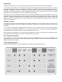
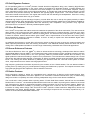
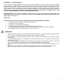
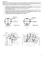
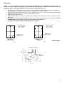
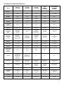
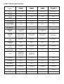
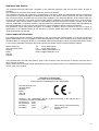
Contents Important information 1 Introduction 2 Speaker Location 2 Fine Tuning & Calibration 2 Timbre Matching Guide 2 Technology 3 In-Ceiling & In-Wall features 4 In-Ceiling installation 5-6 In-Wall installation 7-8 Setting Up In-Ceiling Loudspeakers 9 Fine tuning of In-Ceiling & In-Wall Loudspeakers 9 In-Ceiling Technical Specifications 10 In-Wall Technical Specifications 11 Guarantee & Service 12 Declaration of Conformity 12 Multi-lingual safety warnings (German, Italian, Spanish and French) 13-14 IMPORTANT INFORMATION The CP Series In-Ceiling and In-Wall loudspeakers will provide long term satisfaction in terms of sound quality and reliability provided they are installed correctly, according to the instructions and conditions contained in this manual. Please read this installation guide carefully before proceeding. We assume the installer is trained and skilled in the correct and safe use of hand and power tools and has a working knowledge of local building and fire regulations/codes as well as experience of the conditions/services behind walls and ceilings into which these speakers will be installed. IF IN DOUBT ABOUT YOUR ABILITY TO INSTALL THESE PRODUCTS SAFELY AND CORRECTLY PLEASE CONTACT YOUR LOCAL AUTHORISED MONITOR AUDIO DEALER OR CUSTOM INSTALLER. WARNINGS: A minimum depth of 190mm (7½ Inches) is required for the BR, RS & GS In-Ceiling back box to fit into recess. The BR, RS & GS In-Wall requires 101mm (4 Inches). The Radius In-Ceiling and Stereo In7 Ceiling require a minimum depth of 159mm (6 ¼ Inches) and the Radius In-Wall requires 98mm (3 /8 Inches) The fixing clamps require a minimum of 25mm (1 Inch) of surface area around the cut-out hole to ensure a secure fixing! 3 The fixing clamps will operate on ceilings or walls with a minimum thickness of 9mm ( /8 Inches) to a maximum depth of 32mm (1¼Inches) Do not attempt to fix these speakers to your ceiling or wall if you are unsure of your ability to provide a secure and safe fixing. IF IN DOUBT CONTACT YOUR LOCAL AUTHORISED MONITOR AUDIO DEALER OR CUSTOM INSTALLER. Ensure that there are no water pipes, air ducts or electricity cables running immediately behind the cut out area! Please work from secure steps or scaffold and avoid trailing wires for your safety and those around you. Always turn off the amplifier or other devices in the system when connecting these speakers 1 Introduction Congratulations and thank you for purchasing this high performance Monitor Audio CP Series loudspeaker. In over thirty years, Monitor Audio has become synonymous with high performance, technical excellence, innovation and superior aesthetic design. Our heritage of investment in high-end metal driver and cabinet technology is powerfully expressed by a versatile award-winning range of speakers, which set class-leading standards of sonic excellence and aesthetic appeal. Our now legendary attention to detail ensures that we build the complete loudspeaker for every application, as truthful and transparent as possible. We invest as much care, expertise and research in the smallest loudspeaker as we do in the grandest. In every case, the materials and technology we apply are broadly similar, endowing each speaker with the same accurate tonal signature. Irrespective of architecture ori nt er i ordes i gn,Moni t orAudi o’ sr angegi vesyout hef r eedom t os uppl yhi gh quality sound from a versatile mix of floor, stand, wall and flush-mounted speakers. With Monitor Audio, a home can look and sound beautiful. Speaker Location We strongly recommend that these speakers be installed professionally so that positioning and fine-tuning can be successfully undertaken using sound measuring equipment, coupled with room layout experience and technical knowledge. Your CP series In-Ceiling and In-Wall loudspeakers installed in your home theatre can be used as surround speakers in conjunction with freestanding speakers. If you are unsure about where to locate your surround speakers for optimum performance, please contact your Monitor Audio Dealer for advice. When mounting your speakers in the ceiling, locate the speakers 0.6-2m (2 to 6 feet) behind your listening position. The speakers should be installed 2 to 3m (6 to 10 feet) apart centre to centre. Fine Tuning & Calibration Your amplifier or A/V receiver manual will contain information and detailed instruction on fine tuning/calibrating your system so that the correct balance is achieved between the various speakers. It may be necessary to adjust the CP speakers as described in pages 7. Timbre Matching Guide Illustrating the perfect blend of custom installation & hi-fi speakers for optimal performance. 2 Technology ® MMP Mk2 Anadvancei ndr i vert echnol ogydevel opedf r om Moni t orAudi o’ sor i gi nalMet alMat r i xPol y merconematerial. It uses a high-pressure injection moulding process to achieve different thicknesses at critical points of the cone geometry. MMP® Mk2 provides better stiffness, consistency and tighter production tolerances resulting in superior sonic performance. ® C-CAM Tweeters Advanced software simulation has allowed us to optimise the tweeter design, bringing higher sensitivity and a wider bandwi dt ht or evealt hef i nes thi ghf r equencydet ai lal lt hewayupt o30kHz.We’ vedevel opedas ophi s t i cat ednew chamber with graduated damping, which controls undesirable resonances for a smoother more accurate response. ® C-CAM drivers Developed over many years, C-CAM is used as a cone material for all high frequency drivers, and deployed for midrange and bass drivers in our mid-market and top-of-the-range CI and hi-fi speakers. Created originally by aerospace engineers for jet-engine blades, Ceramic-Coated Aluminium/Magnesium exhibits ideal acoustic properties, being extremely strong but very light in weight. Conventional cone materials are liable to flex in operation, producing a significant level of audible distortion. RST ® Our most refined technology, the RST cone surface is patterned with either concentric dimples or radial ridges, which further reduces mass, increases stiffness and eliminates the bending associated with conventional metal cone designs. The result is a smoother, more agile response, better control of break-up and a wider dynamic range. Not only is RST employed by the Gold Signature range of hi-fi loudspeakers, but also the GS-CP in-ceiling and in-wall models. CP No sound installation is ever the same. CP stands for Controlled Performance, because each CP in-ceiling or in-wall product is fitted with its own rigid mineral filled enclosure allowing the acoustics to be optimised every time. This ensures that its exceptional sound remains consistent wherever it is fitted. High Frequency Switching [H.F] Factory set to 0dB, this offers a sonic balance as the designer intended. However in environments with a high degree of soft furnishings it may be desirable to lift the H.F level to the +3dB setting to achieve a neutral sonic balance. In a minimalist environment it maybe necessary to drop the H.F level to -3dB position. Mid Frequency Switching [M.F] Factory set to 0dB, this offers a sonic balance as the designer intended. However in environments with a high degree of soft furnishings it may be desirable to lift the M.F level to the +3dB setting to achieve a neutral sonic balance. In a minimalist environment it maybe necessary to drop the M.F level to -3dB position. 3 CP Gold Signature Features ® CP GS speakers utilise our C-CAM (Ceramic Coated Aluminium Magnesium alloy) cone, featuring Rigid Surface ® Technology (RST ). I mpr es s i onsont hecone’ ss ur f ace are designed to eliminate bending, increase stiffness and lower mass when compared with conventional cone driver designs. The result is a much faster response, offering music reproduction that is closer to the original performance. A rigid die-cast metal chassis design features a vented rear section and provides extremely low distortion with typically higher output levels. The in-wall model uses the exact same tweeter as that found in the regular stand mount and floor standing GS loudspeakers. Both the in-ceiling and in-wall models extend all the way up to 30KHz. Additional high frequency and mid-range frequency controls allow the user to set-up the system precisely to obtain optimum performance within the listening environment. This inherent flexibility makes the CP GS speakers suitable for a wider range of demanding applications than that offered by their competitors. They pr omi s eat r ul y‘ hi gh-end’ performance from a custom fit, discreetly installed speaker system. CP Silver RS Features Our C-CAM® cone profiles and rubber surrounds maximise the potential of the driver mechanism. The new surrounds allow greater cone excursions with lower distortion and improved frequency response linearity. The flush cone edge provides a very smooth response and a natural, accurate sound. The Silver RS CP pivoting tweeter (In-Ceiling only) ® i sbasedonMoni t orAudi o’ sf amous25mm gol dC-CAM dome. Improvements to the surround and motor system have extended the frequency response to 30KHz, so that it is ready to exploit new wide bandwidth digital audio formats such as SACD and DVD-A. An additional high frequency control offers a fine-tuning option to allow the user to set-up the system precisely and obtain optimum performance within the listening environment. This additional flexibility makes the Silver RS CP InCeiling and In-Wall speakers suitable for a wider range of demanding residential and commercial applications. CP Bronze Reference Features ® The Bronze Reference drive unit, (MMP II) offers an advanced driver technol ogydevel opedf r om Moni t orAudi o’ s ® original Metal Matrix Polymer (MMP ) cone material and uses a high-pressure injection moulding process to achieve ® different thickness at critical points in the cone geometry. MMP II provides better stiffness and consistency and tighter production tolerances resulting in superior sonic performance. The new bass-mid chassis design has a vented rear section that reduces thermal power compression to deliver increased dynamic range and higher sound pressure levels. This venting also lowers distortion by balancing the pressure within the voice-coil motor system. It means clean, crisp bass and an even clearer mid-range performance. ® High frequency performance has been improved by the evolution of the C-CAM tweeter. The new tweeter utilises a pivoting action (In-Ceiling only) to provide optimum imaging and flexible set-up options. The bespoke crossover uses high-grade polypropylene film capacitors, and low distortion inductors CP Radius Features Driver technology refined to del i vert he unpar al l el ed s oni cper f or manc e ofMoni t orAudi o’ sawar d-winning ultracompact Radius loudspeakers has been applied to its successful Controlled Performance (CP) in-wall/in-ceiling designs to render a completely new flush-mounting loudspeaker range for the most discrete installations. ® The in-wall and in-ceiling models utilise a pivoting 20mm C-CAM Gold Dome tweeter, derived from the remarkable Radius R45 hi-fi monitor - the smallest speaker Monitor Audio has ever made. Its pivoting action allows for the critical high frequencies (to 25kHz) to be directed toward the listening position for the most accurate imaging. Radius CP delivers added installation versatility by providing this feature from in-wall as well as in-ceiling locations. The ® innovative in-ceiling stereo design uses dual fixed C-CAM (Ceramic Coated Aluminium Magnesium) domes fed independently with stereo left/right signals. Bass and mid-r angef r equenci esar eaccur at el yr epr oduced bya5” ® version of the acclaimed Radius MMP Mk2 driver. 4 Installation –In-Ceiling Units The CP Series In-Ceiling loudspeakers will provide long term satisfaction in terms of sound quality and reliability provided they are installed correctly, according to the instructions and conditions contained in this manual. Please read this installation guide carefully before proceeding. We assume the installer is trained and skilled in the correct and safe use of hand and power tools, and has a working knowledge of local building and fire regulations/codes as well as experience of the conditions/services behind walls and ceilings into which these speakers will be installed. IF IN DOUBT ABOUT YOUR ABILITY TO INSTALL THESE PRODUCTS SAFELY AND CORRECTLY PLEASE CONTACT YOUR LOCAL AUTHORISED MONITOR AUDIO DEALER OR CUSTOM INSTALLER. NOW AVAILABLE: Pre-construction brackets. These are for use when installing any CP product before the plaster board/ rock wall, is fitted. They show the location of the speakers to the builder and give them a solid secure edge to cut around. Parts List PLEASE CHECK YOU HAVE THE FOLLOWING ITEMS IN THIS KIT BEFORE PROCEEDING: 1 x Complete speaker & tweeter assembly fitted to back box. 1 x Grille (which can be painted). 1 x Mounting cut out template (in packaging). 1 x Plastic paint mask (for covering the baffle while painting the frame) 1 x Self adhesive grille membrane (to be attached to the inside the grille after it has been painted). 2 x Spare baffle fixing screws plus guarantee card in this manual. WARNINGS: A minimum depth of 190mm (7½ Inches) is required for the back box on the BR, RS & GS In-Ceiling products to fit into recess. The Radius In-Ceiling Products require 159mm (6 ¼ Inches). The fixing clamps require a minimum of 25mm (1 Inch) of surface area around the cutout hole to ensure a secure fixing! The fixing clamps will operate on ceilings with a minimum thickness of 9mm (3/8 Inches) to a maximum depth of 32mm (1¼ Inches). Do not attempt to fix these speakers to your ceiling if you are unsure of your ability to provide a secure and safe fixing. IF IN DOUBT CONTACT YOUR LOCAL AUTHORISED MONITOR AUDIO DEALER. Ensure that there are no water pipes, air ducts or electricity cables running immediately behind the cut out area! Please work from secure steps or scaffold and avoid trailing wires for your safety and those around you. Always turn off the amplifier or other devices in the system when connecting these speakers. 5 Procedure NOTE: If you are choosing to paint your In-Ceiling loudspeaker, we recommend you do this prior to installation. We would also recommend using the paint mask for the baffle. Remove the mask after paint has completely dried. Fit the grille membrane to the inside of the grille after painting. 1. Use template to locate position of cut out. Fig 1 for BR, RS & GS In-Ceiling Products and Fig 2 for Radius InCeiling products. The adhesive backing allows for repositioning a number of times. 7 2. Draw around the template to define the circumference of the cut out - 250mm ( 9 /8 inches ) for BR, RS & GS 13 In-Ceiling products, 173mm (6 /16 Inches) for Radius Inceiling products 3. Remove template and cut hole. 4. Locate speaker cable and connect by pushing the terminals in and releasing to clamp the cables as shown below Fig 3 for Radius, BR, RS & GS In-Ceiling Products and Fig 4 for Radius Stereo In-Ceiling. 5. Fit back box into prepared hole and tighten fixing clamps. These will move outwards on tightening! DO NOT OVERTIGHTEN! Once contact is made 2-3 turns are all that is required. 6. TO FINE-TUNE THE SPEAKERS PLEASE REFER TO PAGE 9. Hole to be cut 250mm ( 9 7/8” ) Diameter Hole to be cut 173mm (6 13/16” ) Diameter Position of 4 fixing clamps BR, RS, GS In-Ceiling Template Not to scale Fig 1 Position of 4 fixing clamps Radius In-Ceiling Template Not to scale Fig 2 Push down to fit cable Push down to fit cable Red (Positive) Black (Negative) Red (Positive) Fig 3 Black (Negative) Fig 4 6 Installation - In-Wall Units The CP Series In-Wall loudspeakers will provide long term satisfaction in terms of sound quality and reliability provided they are installed correctly, according to the instructions and conditions contained in this manual. Please read this installation guide carefully before proceeding. We assume the installer is trained and skilled in the correct and safe use of hand and power tools, and has a working knowledge of local building and fire regulations/codes as well as experience of the conditions/services behind walls and ceilings into which these speakers will be installed. IF IN DOUBT ABOUT YOUR ABILITY TO INSTALL THESE PRODUCTS SAFELY AND CORRECTLY PLEASE CONTACT YOUR LOCAL AUTHORISED MONITOR AUDIO DEALER OR CUSTOM INSTALLER. NOW AVAILABLE: Pre-construction brackets. These are for use when installing any CP product before the plaster board/ rock wall, is fitted. They show the location of the speakers to the builder and give them a solid secure edge to cut around. Parts List PLEASE CHECK YOU HAVE THE FOLLOWING ITEMS IN THIS KIT BEFORE PROCEEDING: 1 x Complete speaker & tweeter assembly fitted to back box. 1 x Grille (which can be painted). 1 x Mounting cut out template (in packaging). 1 x Plastic paint mask (for covering the baffle while painting the frame) 1 x Self adhesive grille membrane (to be attached to the inside the grille after it has been painted). 2 x Spare baffle fixing screws plus guarantee card in this manual. WARNINGS: A minimum depth of 101mm (4 Inches) is required for the back box on the BR, RS & GS In-Wall products to 7 fit into wall/ceiling recess. The Radius In-Wall requires 99mm (3 /8 Inches). The fixing clamps require a minimum of 25mm (1 Inch) of surface area around the cut-out hole to ensure a secure fixing! 3 The fixing clamps will operate on walls with a minimum thickness of 9mm ( /8 Inches) to a maximum depth of 32mm (1¼ Inches). Do not attempt to fix these speakers to your wall if you are unsure of your ability to provide a secure and safe fixing. IF IN DOUBT CONTACT YOUR LOCAL AUTHORISED MONITOR AUDIO DEALER. Ensure that there are no water pipes, air ducts or electricity cables running immediately behind the cut out area! Please work from secure steps or scaffold and avoid trailing wires for your safety and those around you. Always turn off the amplifier or other devices in the system when connecting these speakers. 7 Procedure NOTE: If you are choosing to paint your In-Ceiling loudspeaker, we recommend you do this prior to installation. We would also recommend using the paint mask for the baffle. Remove the mask after paint has completely dried. Fit the grille membrane to the inside of the grille after painting. 1. Use template to locate position of cut out. Fig 1 for BR, RS & GS In-Ceiling Products and Fig 2 for Radius InCeiling products. The adhesive backing allows for repositioning a number of times. 3 2. Draw round the perimeter of the cut out –387 x 234mm (15 ¼ x 9 /16 inches ) for BR, RS & GS In-Wall 13 products, 275 x 172mm (10 /16 x 6 ¾ Inches) for Radius In-Wall 3. Remove template and cut hole. 4. Locate speaker cable and connect by pushing the terminals in and releasing to clamp the cables as shown below Fig 3. 5. Fit back box into prepared hole and tighten fixing clamps. These will move outwards on tightening! DO NOT OVERTIGHTEN! Once contact is made 2-3 turns are all that is required. 6. TO FINE-TUNE THE SPEAKERS PLEASE REFER TO PAGE 9. Hole size to be cut 387 x 234mm ( 1 5¼“x93/16”) Hole size to be cut 275 x 172mm (10 13/16 ”x6¾”) Position of 6 fixing clamps Position of 8 fixing clamps BR, RS, GS In-wall template Radius In-wall template Fig 2 Fig 1 Not to scale Push down to fit cable Red (Positive) Black (Negative) Fig 3 8 Setting Up CP Loudspeakers The following adjustments can be made to the tweeter on CP models except BR, RS & GS In-Wall, as follows: 1. 2. 3. 4. Pivoting tweeters can be tilted up to 18 degrees in all directions to provide optimum coverage. If the speakers are widely separated such that the music fails to blend into a central image when operated in stereo mode then tilt the tweeter towards the listening area. If the Soundstage seems too confined tilt the tweeter away from the listening area. For further fine-tuning options of your CP In-Ceiling speakers please go to page 8. Fine-tuning - In-Ceiling and In-wall speakers The following adjustments can be made to your CP In-Ceiling and In-Wall loudspeakers as follows: Adjusting H.F (High Frequency) control (Silver RS CP and Gold CP models only) The factory H.F setting provides a flat or 0dB level, which will suit the majority of typical installations. However, it is possible to fine-t unet hes oundf r om t heCPs peaker st os ui tar oom’ s characteristics or preferred listening tastes by using the following as a guide: a. Setting the switch in the +3dB position will add brightness and additional clarity to the system. This may be effective in a room with a large amount of soft furnishings. b. Setting the switch in the -3dB position will reduce the brightness on the system and provide a duller sound. This may be effective in a room with a lack of soft furnishings, or in an installation with a wooden floor. Adjusting M.F (Mid-range Frequency) control (Gold CP models only) The factory M.F setting provides a flat or 0dB level, which will suit the majority of typical installations. However, it is possible to fine-tune the sound from the Gold CP In-Ceiling and In-Wall s peaker st os ui tar oom’ scharacteristics or preferred listening tastes by using the following as a guide: a. Setting the switch in the +3dB position will add presence and additional clarity to the system, particularly in the vocal region. This may be effective for better resolution of dialogue and speech, or in an installation where the listening position is a large distance from the speaker. b. Setting the switch in the -3dBpos i t i onwi l lr educet hepr es enceandt hes ys t em wi l ls oundmor e‘ l ai dback’ . This may be effective where the speaker will be played for background music, or where the listening position is situated close to the speaker. 9 In-Ceiling Technical Specifications CPC GS In-Ceiling CPC RS In-Ceiling CPC BR In-Ceiling CPC RADIUS In-Ceiling CPC RADIUS In-Ceiling STEREO Frequency Response 55Hz –30KHz 60Hz –30KHz 62Hz –22 KHz 60Hz –25KHz 60Hz –25KHz Impedance (nominal) 8 Ohms 8 Ohms 8 Ohms 6 Ohms 6 + 6 Ohms Sensitivity (1W@1M) 89dB 89dB 88dB 88 dB 88 dB Maximum SPL 106.5 dBA 105.8 dBA 105 dBA 103 dBA 103 dBA (both channels driven) Power Handling 120W 100W 80W 70W 35W / x 2 (total 70W) Recommended Amp Requirements 30-120W 30-100W 20-80W 5-60W 5-30W x 2 Bass Alignment Sealed enclosure Sealed enclosure Sealed enclosure Sealed enclosure Sealed enclosure Drive Unit Complement Bass 1x6. 5”C-CAM bass driver featuring RST technology 1x6”C-CAM bass driver 1x6. 5”MMP2 second generation Metal Matrix Polymer 1x5”MMP2 bass driver 1x5”MMP2bass driver Drive Unit Complement Tweeter Pivoting 25mm CCAM gold alloy dome with high power ceramic magnet system Pivoting 25mm CCAM gold alloy dome with rare earth magnet Pivoting 25mm C-CAM gold alloy dome with rare earth magnet Pivoting 20mm ® C-CAM gold alloy dome 2 x 20mm ® C-CAM gold alloy dome Overall Diameter 281mm 1 (11 /16 inches) 281mm 1 (11 /16 inches) 281mm 1 (11 /16 inches) 214 DIA (mm) 7 8 /16 (Inches) 214 DIA (mm) 7 8 /16 (Inches) Overall Depth 181mm 1 (7 /8 inches) 181mm 1 (7 /8 inches) 181mm 1 (7 /8 inches) 155 (mm) 1 6 /8 (Inches) 155 (mm) 1 6 /8 (Inches) Cut-Out Hole Diameter 250mm 7 (9 /8 inches) 250mm 7 (9 /8 inches) 250mm 7 (9 /8 inches) Recommended Mounting Depth. mm (inch) 190mm (7 ½ ) 190mm (7 ½ ) 190mm (7 ½ ) 150mm (6) 150 (6) Controls +3db / 0dB / -3dB High frequency attenuation witch. +3db / 0dB / -3dB Mid-range frequency attenuation switch. +3db / 0dB / -3dB High frequency attenuation switch N/A N/A N/A Fixing type 4posi t i on‘ dog’ type fixings 4posi t i on‘ dog’ type fixings 4posi t i on‘ dog’ type fixings 4posi t i on‘ dog’ type fixings 4posi t i on‘ dog’ t y pe fixings Connection Gol dpl at ed‘ push’ type terminals Gol dpl at ed‘ push’ type terminals Gold plated ‘ push’ t y pe terminals Gold plated ‘ push’ t y pe terminals Gol dpl at ed‘ push’ type terminals Model 6 173 (mm) /16 (Inches) 13 6 173 (mm) /16 (Inches) 13 Baffle material MDF MDF MDF ABS ABS Back Box/ Material Mineral filled ABS plastic (UL –94 V0 fire rated) Mineral filled ABS plastic (UL –94 V0 fire rated) Mineral filled ABS plastic (UL –94 V0 fire rated) Mineral filled ABS plastic (UL - 94 V0 fire rated) Mineral filled ABS plastic (UL - 94 V0 fire rated) PreConstruction CB 8 (Green) CB 8 (Green) CB 8 (Green) CB 5 (Blue) CB 5 (Blue) Unit weight Kg (lb) 3.1Kg (6.8Ib) 2.5Kg (5.5Ib) 2.4Kg (5.3lb) 1.55Kg (3.4lb) 1.6Kg (3.5lb) 10 In-Wall Technical Specifications CPW GS In-Wall CPW RS In-Wall CPW BR In-Wall CPW RADIUS In-wall Frequency Response 55Hz –30KHz 60Hz –30KHz 62Hz –22 KHz 60Hz –25KHz Impedance (nominal) 8 Ohms 8 Ohms 8 Ohms 6 Ohms Sensitivity (1W@1M) 89dB 89dB 88dB 88 dB Maximum SPL 106.5 dBA 105.8 dBA 105 dBA 103 dBA Power Handling 120W 100W 80W 70W Recommended Amp Requirements 30-120W 30-100W 20-80W 5-60W Bass Alignment Sealed enclosure Sealed enclosure Sealed enclosure Sealed enclosure Drive Unit Complement – Bass 1x6. 5”C-CAM bass driver featuring RST technology 1x6”C-CAM bass driver 1x6. 5”MMP2second generation Metal Matrix Polymer 1x5”MMP2bass driver Drive Unit Complement Tweeter 25mm C-CAM gold alloy dome with high power ceramic magnet system and rear low resonance chamber 25mm C-CAM gold alloy dome with rare earth magnet 25mm C-CAM gold alloy dome with rare earth magnet Pivoting 20mm C® CAM gold alloy dome Overall Size HxW (Inches) 423 x 270mm 5 5 (16 /8 x 10 /8 ) 423 x 270mm 5 5 (16 /8 x 10 /8 ) 423 x 270mm 5 5 (16 /8 x 10 /8 ) 313 x 212mm 5 5 (12 /16 x 8 /16 ) Overall Depth (Inches) 100mm 15 (3 /16 ) 100mm 15 (3 /16 ) 100mm 15 (3 /16 ) 99mm 7 (3 /8 ) Cut-Out Hole Size HxW (Inches) 387 x 234mm 3 (15 ¼ x 9 /16 ) 387 x 234mm 3 (15 ¼ x 9 /16 ) 387 x 234mm 3 (15 ¼ x 9 /16 ) 275 x 172mm 13 (10 /16 x 6 ¾ ) Recommended Mounting Depth 101mm (4 inches) 101mm (4 inches) 101mm (4 inches) 95mm 3 ¾ (Inches) Controls +3db / 0dB / -3dB High frequency attenuation switch. +3db / 0dB / -3dB Mid-range frequency attenuation switch. +3db / 0dB / -3dB High frequency attenuation switch N/A N/A Fixing Type 8posi t i on‘ dog’ t y pe fixings 8posi t i on‘ dog’ t y pe fixings 8posi t i on‘ dog’ t y pe fixings 6posi t i on‘ dog’ t y pe fixings Connection Gol dpl at ed‘ push’t y pe terminals Gol dpl at ed‘ push’t y pe terminals Gol dpl at ed‘ push’t y pe terminals Gold pl at ed‘ push’t y pe terminals Baffle Material MDF MDF MDF ABS Back Box Material Mineral filled ABS plastic (UL –94 V0 fire rated) Mineral filled ABS plastic (UL –94 V0 fire rated) Mineral filled ABS plastic (UL –94 V0 fire rated) Mineral filled ABS plastic (UL –94 V0 fire rated) Pre-Construction Bracket WB 8 (Green) WB 8 (Green) WB 8 (Green) WB 5 (Blue) Unit Weight Kg (lb) 4.4Kg (9.6Ib) 3.2Kg (7Ib) 3.3Kg (7.2lb) 1.83Kg (4.1lb) Model 11 Guarantee and Service The guarantee becomes valid upon completion of the attached guarantee card and its return within 30 days of purchase. This guarantee is void if the serial number has been removed or defaced. This equipment has been fully tested prior to dispatch from the factory. Both the craftsmanship and the performance of this product is guaranteed against manufacturing defects for the period of three years from the date of purchase (see conditions below), provided that the product was supplied by an authorised Monitor Audio retailer under the consumer sal eagr eement .( Thewor ds‘ cons umers al e’s hal lbecons t r uedi naccor dancewi t hs ect i on15oft hes uppl y of goods act 1973). Monitor Audio accepts no responsibility for defects arising from accident, misuse, abuse, wear and tear, modification or operation outside of that specified within this instruction manual. Neither will responsibility be accepted for damage or loss occurring during transit to or from the parties claiming under this guarantee. This guarantee covers both labour and parts. The liability of Monitor Audio is limited to the cost of repair or replacement of the defective parts (at the discretion of Monitor Audio) and under no circumstances extends to consequential losses or damage. Claims under this Guarantee The equipment should be returned in its packaging to the original supplier where possible, or to any other authorised Monitor Audio dealer. If it is not possible to return the equipment by hand, then it should be sent carriage prepaid via a reputable carrier. If the original packing is not available replacement packaging can be purchased from Monitor Audio. If you have any difficulties complying with these requirements please contact us at the following address: Monitor Audio Ltd. Unit 2, 24 Brook Road Rayleigh Essex SS6 7XL England Tel: 44 (0) 1268 740580 Fax: 44 (0) 1268 740589 Internet: www.monitoraudio.co.uk Email: [email protected] This guarantee does not affect the statutory rights of the consumer under UK law and or relevant consumer laws in other countries or states. Monitor Audio reserve the right to alter specifications at any time without notice if it is considered that an improvement can be made to the product. Declaration of Conformity Low Voltage Directive 2006/95/EC Electromagnetic Compatibility Directive 89/336/EEC We, Monitor Audio Ltd. 24 Brook Road Rayleigh Essex SS6 7XL England 07 Declare in own responsibility, that the products described in this manual are in compliance with technical standards: EN 61000-6-1 : 2001 EN 61000-6-3 : 2007 EN 55013 : 2001 Dean Hartley (Technical Director) EN 50020 : 2002 Monitor Audio Ltd England 12 Warnungshinweis Die zum Wand/Decken-Einbau vorgesehenen Lautsprecher der CP Serie werden Ihnen auf lange Zeit mit ihrer vorzüglichen Tonqualität und Zuverlässigkeit viel Freude bereiten, vorausgesetzt, dass sie vorschriftsmäßig nach den in diesem Handbuch angegebenen Anleitungen und Bedingungen eingebaut werden. Lesen Sie bitte vor Beginn der Arbeiten diese Installationsanleitungen sorgfältig, da wir voraussetzen, dass der Installateur im vorschriftsmäßigen und sicheren Gebrauch von Elektrowerkzeugen unterwiesen und erfahren ist. Es wird ebenso vorausgesetzt, dass er ausreichende Kenntnisse der örtlichen Bau und Brandschutzbestimmungen besitzt, sowie entsprechende Erfahrung des Unterputzzustandes und der eventuell vorhandenen Leitungen in Wänden und Zimmerdecken besitzt, in welche diese Lautsprecher eingebaut werden sollen. SOLLTEN SIE DARAN ZWEIFELN; DIESE ARBEITEN MIT SICHERHEIT- UND ORDNUNGSGEMÄSS AUSFÜHREN ZU KÖNNEN, WENDEN SIE SICH BITTE AN IHREN AUDIO-VERTRAGSHÄNDLER. WARNUNGSHINWEIS: Es wird eine Mindesteinbautiefe von 190 mm (7.5 Zoll ) für den Deckeneinbau der Backbox benötigt. Für den Wandeinbau sind 98 mm (4 Zoll) vorzusehen. Die Befestigungsklemmen benötigen eine Oberfläche von 25 mm (1 Zoll) um das ausgeschnittene Loch herum, um eine sichere Befestigung zu gewähren! Die Befestigungsklemmen können bei Decken oder Wänden mit einer Mindestdicke von 9 mm (0,35 I) bis zu einer Mindesttiefe von 32 mm (1,25 Zoll) angewendet werden Versuchen Sie nicht, diese Lautsprecher an Ihrer Wand oder Decke anzubringen, wenn Sie nicht voll überzeugt sind, dass Sie imstande sind, diese vorschriftsmäßig und sicher zu montieren. IM ZWEIFELSFALLE WENDEN SIE SICH BITTE AN IHREN ZUGELASSENEN ÖRTLICHEN AUDIOHÄNDLER. Vergewissern Sie sich, dass sich keine Wasser- Luft- oder Elektroleitungen hinter dem Ausschnitt befinden! Benutzen Sie bitte immer nur sichere Tritte oder Leitergerüste und vermeiden Sie im Interesse Ihrer Sicherheit sowie der aller anwesenden Personen herabhängende und auf dem Boden schleifende Kabel und Leitungen. Bei Anschluss dieser Lautsprecher müssen die Verstärker sowie alle weiteren Geräte im System ausgeschaltet sein. Avvertimenti La Serie CP di altoparlanti incassati nel soffitto e nelle pareti offrirà un ottimo funzionamento in termini di qualità Sonora ed affidabilità, purché gli altoparlanti siano installati correttamente, seguendo le istruzioni e le condizioni contenute in questo manuale. Si prega di leggere attentamente questa g ui d aa l l ’ i ns t a l l a z i onep r i mad ip r o c e de r e ,po i c h ép r e s umi a moc hel ’ i n s t a l l a t o r es i aa d de s t r a t oes i ai ng r a d od iut i l i z z a r eg l ia t t r e z z ima n ua l ie de l e t t r i c i . Eda bb i ai no l t r eun ac onos c e nz ao pe r a t i v ade l l ’ e di f i c i ol oc a l eed e l l eno r me / c o d i c ia n t i nc e nd i oec on os c al e condizioni/i servizi dietro pareti e soffitti nei quali saranno installati questi altoparlanti. IN CASO DI DUBBI SULLA PROPRIA ABILITÀ AD EFFETTUARE QUESTA INSTALLAZIONE IN MODO CORRETTO E SICURO, SI PREGA DI CONTATTARE IL PROPRIO CONCESSIONARIO LOCALE AUTORIZZATO ALLA VENDITA DI APPARECCHI AUDIO. ATTENZIONE: E’necessar i aunapr of ondi t àmi ni madi190mm per chél acassapost er i or epossaesser ei nst al l at anelv anodel soffitto. Quella da incassare nella parete necessita di uno spazio di 98 mm. I dispositivi di fissaggio necessitano di una superficie minima di 25 mm intorno al foro intagliato per assicurare un fissaggio sicuro! I dispositivi di fissaggio saranno funzionali in soffitti e pareti che abbiano uno spessore di almeno 9 mm fino ad uno spessore massimo di 32 mm. Non si deve tentare di fissare questi altoparlanti in un soffitto o una parete se non si è certi della propria abilità di effettuare un’ i nst al l az i one appr opr i at a e si cur a.IN CASO DI DUBBI CONTATTARE IL PROPRIO CONCESSIONARIO LOCALE AUTORIZZATO ALLA VENDITA DI APPARECCHI AUDIO. Accer t ar si chenonv isi anodit ubidel l ’ acqua,condot t id’ ar i aocav iel et t r i ci i nst al l at iappenadi et r ol ’ ar eai nt agl i at a! Lavorare su scale o impalcature sicure ed evitare di tirare dei fili per la propria sicurezza e quella di altre persone. Spegner esempr el ’ ampl i f i cat or eoal t r i di sposi t i v idel l ’ i mpi ant oquandosi col l eganoquest ial t opar l ant i . 13 Advertencias La CP Series de altavoces de empotrado en el techo y en la pared ofrecerán una satisfacción a largo plazo en concepto de calidad del sonido y fiabilidad, siempre y cuando se instalen correctamente, según las instrucciones y condiciones contenidas en este manual. Antes de proceder, lea detenidamente esta guía de instalación en la que se supone que el instalador está capacitado y es hábil en el uso correcto y seguro de herramientas manuales y eléctricas, y que tiene conocimientos prácticos de las regulaciones / códigos locales en materia de construcción e incendios, así como experiencia en cuanto a las condiciones / servicios que se encuentran detrás de los techos y paredes en los que se instalarán estos altavoces. EN CASO DE DUDA DE QUE SEA CAPAZ DE INSTALAR ESTOS DISPOSITIVOS DE UNA MANERA SEGURA Y CORRECTA, SÍRVASE CONTACTAR CON SU DISTRIBUIDOR AUTORIZADO LOCAL DE AUDIO MONITORES ADVERTENCIAS: Se requiere una profundidad mínima de 190 mm (7,5 pulgadas) para que la caja de respaldo de empotrado en el techo quepa en el rebaje. La de empotrado en la pared requiere de 98 mm (4 pulgadas) ¡Las grapas de fijación requieren un área de superficie de 25 mm (1 pulgada), como mínimo, alrededor del agujero perforado para garantizar una fijación segura! Las grapas de fijación servirán en techos o paredes con un espesor mínimo de 9 mm (0,35 pulgadas) hasta una profundidad máxima de 32 mm (1,25 pulgadas) No intente instalar estos altavoces en el techo o pared si no está seguro de que sea capaz de ofrecer una instalación correcta y segura . EN CASO DE DUDA CONTACTE CON SU DISTRIBUIDOR AUTORIZADO LOCAL DE AUDIO MONITORES. ¡Cerciórese de que no haya tuberías de agua, ductos de aire o cables eléctricos que pasen inmediatamente por detrás del área perforada! Para la instalación use por favor escaleras o andamiaje y evite dejar alambres colgados por su propia seguridad y la de los que le rodean. Siempre apague el amplificador u otros dispositivos del sistema cuando conecte estos altavoces. Avertissements La série CP de haut-parleurs encastrés dans les murs et les plafonds fourniront une satisfaction à long terme quant à la qualité du son et à la fiabilité, à c ond i t i ond ’ ê t r ei ns t a l l é sc o r r e c t e me n t ,c o nf o r mé me n ta uxi ns t r uc t i o nse ta uxc on di t i onsc on t e n ue sd a nsc e t t eno t i c e .Lisez attentivement cette notice a v a n tdec omme nc e rl ’ i ns t a l l a t i o n.No uss uppos onsq uel ’ i ns t a l l a t e ure s tf o r mée tc omp é t e n te tq u’ i ls a i tut i l i s e rl e so ut i l sàma i ne tl e so ut i l s é l e c t r i q ue sc o r r e c t e me nte td ’ unema n i è r es ûr e .No uss up pos o nsé g a l e me n tq u’ i launec onn a i s s a nc ep r a t i q uede sr è g l e me nt s / c ode sl oc a uxr e l a t i f sa ux constructions et aux i n c e nd i e se tq u’ i laun ee xp é r i e nc ede sc on di t i o ns / s e r v i c e sde r r i è r el e smur se tl e spl a f on dsd a nsl e s q ue l sc e sh a ut -parleurs seront installés. SI VOUS AVEZ UN DOUTE QUELCONQUE SUR VOTRE CAPACI TÉ D’ I NSTALLER CES HAUT-PARLEURS CORRECTEMENTETD’ UNEMANI ÈRESÛRE, CONTACTEZ VOTRE REVENDEUR LOCAL AGRÉÉ DE MATERIEL HI-FI. AVERTISSEMENTS : I lf autunepr of ondeurd’ aumoi ns190mm pourencast r erl eboî t i erar r i èr edansl eplafond. La profondeur nécessaire pour l ’ encast r ementdansl emur est de 98 mm. Les bridesdef i x at i onontbesoi nd’ unesur f aced’ env i r on25mm aut ourdut r oudécoupépourf our ni runef i x at i onf er me! Lesbr i desdef i x at i onsontadéquat espourêt r eut i l i séessurdespl af ondsetdesmur sd’ uneépai sseurmi ni mum de9mm et d’ unepr of ondeurmax i mum de 32 mm. N’ essay ezpasdef i x erceshaut -par l eur sdansv ot r epl af ondoudansv ot r emursiv ousn’ êt espascer t ai ndepouvoi robt eni r une fixation ferme et sûre. EN CAS DE DOUTE, CONTACTEZ VOTRE REVENDEUR LOCAL AGRÉÉ DE MATERIEL HI-FI. Assurez-vousqu’ i ln’ yapasdecondui t esd’ eau,decondui t sd’ ai rnidecâbl esél ect r i quesj ust eder r i èr el ’ endr oi tpr év u d’ encast r ement . Travaillez sur un escabeau ou sur un échafaudage sûr et évitez de laisser traîner des fils électriques pour votre sécurité et celle de ceux autour de vous. Met t ezt ouj our shor st ensi on l ’ ampl i f i cat eurou l es aut r esdi sposi t i f sdansl esy st ème l or sque v ousconnect ezces haut parleurs. © 2004 Monitor Audio Ltd. 24 Brook Road, Rayleigh, Essex SS6 7XL England Revision version 6 14