1
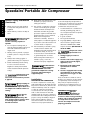
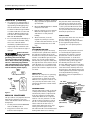
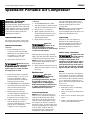
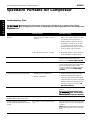
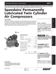
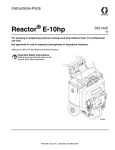
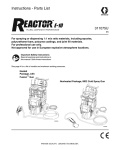
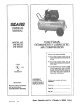
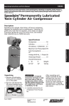
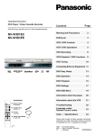
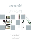
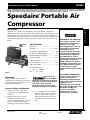
5Z598C
Operating Instructions & Parts Manual
Please read and save these instructions. Read carefully before attempting to assemble, install, operate or maintain the
product described. Protect yourself and others by observing all safety information. Failure to comply with instructions
could result in personal injury and/or property damage! Retain instructions for future reference.
Speedaire Portable Air
Compressor
®
Description
Speedaire one cylinder, low maintenance, oil-less portable air compressor is
designed for home, farm, and medium duty industrial uses with a 50/50 duty cycle.
The 2 HP pump and motor assembly on a 3 gallon capacity air tank is equipped
with check valve, unloader valve, pressure switch, safety valve, air regulator, and a
tank pressure gauge. Motor includes automatic thermal overload protection. UL
listed.
#721Y
Specifications
Motor HP ......................................................... 2
Cylinders ..................................................... One
Air Delivery - SCFM @ 40 psi ........................ 4.5
Air Delivery - SCFM @ 90 psi ........................ 3.2
Maximum Air Pressure (psi) ...................... 135
Compressor RPM ...................................... 1725
Tank Size (Gallons) .......................................... 3
Voltage @ 60 Hz, 1-Phase ......................... 120
Amperage (Amps) ........................................ 15
Overall Dimensions
L
W H
Weight
Figure 1
26” 8”
19”
E
N
G
L
I
S
H
Breathable Air Warning
This compressor/pump is not
equipped and should not be
used “as is” to supply
breathing quality air. For any
application of air for human
consumption, the air
compressor/pump will need to
be fitted with suitable in-line
safety and alarm equipment.
This additional air to meet
minimal specifications for Grade
D breathing is described in
Compressed Gas Association
Commodity Specification G 7.1 1966, OSHA 29 CFR 1910.134 in
the United States and/or
Canadian Standards Association
(CSA).
39 lbs.
DISCLAIMER OF WARRANTIES
Unpacking
After unpacking the unit, inspect
carefully for any damage that may have
occurred during transit. Check for loose,
damaged or missing parts.
Never spray in a
closed area. Motor
and pressure switch may spark when
operating, if sparks come in contact
with vapors from gasoline,
flammable paint or solvents, they
may ignite causing fire or explosion.
General Safety Information
1.
Never touch the air compressor
head during or immediately after
operation.
2.
Operate compressor in a well
ventilated area that is free of
gasoline, flammable paint or solvent
vapors. If spraying a flammable
material, provide ample ventilation.
Form 5S3191
3.
Do not adjust, remove, or tamper
with the safety valve or pressure
switch. If safety valve or pressure
switch replacement is necessary, a
part with the same rating must be
used.
Printed in U.S.A.
03465
0899/287/VCPVP
In the event the compressor is
used for the purpose of
breathing air application and
proper in-line safety and alarm
equipment is not
simultaneously used, existing
warranties shall be voided, and
Dayton Electric Mfg. Co.
disclaims any liability
whatsoever for any loss,
personal injury or damage.
®
D23820-1
5Z598C
Speedaire Operating Instructions and Parts Manual
Speedaire Portable Air Compressor
®
E
N
G
L
I
S
H
General Safety Information
(Continued)
10. Read labels and safety data for all
materials you spray. Follow all
safety precautions.
4.
11. Use a mask or respirator if there is
a chance of inhaling toxic sprayed
materials. Masks and respirators
have limits and will only provide
protection against some kinds and
limited amounts of toxic material.
Read mask and respirator
instructions carefully. Consult a
safety expert or industrial hygienist
if you are not sure about the use of
a certain mask or respirator.
5.
Never use a motor with a higher
horsepower rating than the one
supplied.
Never drill into, weld or modify air
tank.
Changing air tank
will cause it to
weaken. Tank may rupture or
explode.
6.
7.
Do not repair a leaking tank, it
must be replaced. Never replace air
tank with a different model or
larger tank.
Never point any nozzle or sprayer
toward a person or any part of the
body.
8.
Always wear safety goggles or
glasses when using air compressor.
9.
Check maximum pressure rating
for air tools and accessories.
Regulator outlet pressure must
never exceed maximum pressure
rating.
Damage may occur
to air tools and
accessories if too much air pressure
is applied.
Always unplug air
compressor prior
to maintenance or repair. Never use
air compressor outdoors when it is
raining.
Never directly
inhale the
compressed air produced by this
unit. Compressed air contains toxic
or irritating vapors which are
harmful if inhaled.
12. If the material you intend to spray
contains trichloroethane and
methylene chloride (read the label
or the data sheet), do not use
accessories that contain aluminum
or galvanized parts. You must
either change the material you
intend to spray, or use only
stainless steel spray equipment.
Trichloroethane
and methylene
chloride can also react with
galvanized components causing
corrosion and weakening of
equipment parts.
Installation
LOCATION OF AIR COMPRESSOR
Locate air compressor in a clean, dry,
well ventilated area. Air filter must be
kept clear of obstructions, which could
reduce air delivery of the air compressor. The air compressor should be
located at least 12” away from the
wall or other obstructions that will
interfere with air flow. Air compressor
head and shroud are designed to allow
proper cooling. If humidity is high, air
filter can be installed to remove
excessive moisture. Follow air filter
instructions for proper installation.
2
EXTENSION CORD
To avoid voltage drop and power loss
to the motor use extra air hose instead
of an extension cord. If an extension
cord must be used, be sure it is:
1.
A 3-wire extension cord that has a
3-blade grounding plug, and a 3slot receptacle that will accept the
plug on the product.
2.
In good condition.
3.
No longer than 50 feet.
4.
12 gauge (AWG) or larger. Wire
size increases as guage number
decreases. 10 AWG and 8 AWG
may also be used. (DO NOT USE A
14 OR 16 AWG.)
Compressor can be
operated on a 15
amp circuit if:
1. Voltage supply to circuit is
normal.
2. Circuit is not used to supply any
other electrical needs (lights,
appliances, etc.)
3. Extension cords comply with
specifications in owners
manual.
4. Circuit is equipped with 15 amp
circuit breaker or 15 amp time
delay fuse. Use a Type "T" time
delay fuse.
If any of the above conditions cannot
be met, or if operation of the compressor repeatedly causes interruption of
the power, it may be necessary to
operate it from a 20 amp circuit. It is
not necessary to change the cord set.
GROUNDING INSTRUCTIONS
Improper
grounding can
result in electrical shock. In the
event of a short circuit, grounding
reduces risk of shock by providing
an escape wire for the electric
current. Air compressor must be
properly grounded.
Speedaire Operating Instructions and Parts Manual
Model 5Z598C
Installation (Continued)
1. Air compressor is equipped with a
cord having a ground wire with an
appropriate grounding plug. Plug
must be used with an outlet that
has been installed and grounded in
accordance with all local codes and
ordinances. Outlet and plug must
have the same configuration. DO
NOT USE AN ADAPTER.
2.
Do not modify the provided plug. If
it does not fit the available outlet,
the correct outlet should be
installed by a qualified electrician.
3.
Inspect plug and cord before each
use. Do not use if there are signs of
damage.
Risk of electrical
shock. If repairing
or replacing cord or plug, the
grounding wire must be kept
separate from the current-carrying
wires. Never connect the grounding
wire to a flat blade plug terminal.
(The grounding wire has insulation
with an outer surface that is green –
with or without yellow stripes.)
White
Wire
Ground
Outlet
15 AMP
Plug
Grounded
Outlet
Grounding
Pin
Figure 2
BREAK-IN PROCEDURES
This procedure is only required the first
time the air compressor is put into
service and when the check valve has to
be replaced.
1. Set the pressure switch OFF/AUTO
lever to the OFF position.
2.
Plug power cord into the correct
branch circuit receptacle.
3.
Turn regulator clockwise, opening it
fully, to prevent air pressure buildup in the tank.
4.
Move the OFF/AUTO lever to AUTO.
Compressor will start.
5.
Run the compressor for 15 minutes.
Make sure the regulator is open
and there is no tank pressure
buildup.
6.
After 15 minutes, close the
regulator by turning it counterclockwise. Air tank will fill to cut-out
pressure and then the motor will
stop.
Operation
AIR COMPRESSOR PUMP
To compress air, the piston moves up
and down in the cylinder. Air is drawn in
through the air intake valves on the
downstroke of the piston. Exhaust valve
remains closed. On the upstoke of the
piston, air is forced out through the
exhaust valve, through the outlet tube,
through the check valve and into the air
tank. Working air is not available until
the compressor has raised the air tank
pressure above what is required at the
air outlet.
CHECK VALVE
When the air compressor is operating,
the check valve is "open", allowing
compressed air to enter the air tank.
When the air compressor reaches "cutout" pressure, the check valve closes,
allowing air pressure to remain inside
the air tank.
UNLOADER VALVE
The unloader valve located on the side
of the pressure switch, is designed to
automatically release compressed air
from the compressor head and the
outlet tube when the air compressor
reaches "cut-out" pressure or is shut
off. Motor will not be able to start if
the air is not released. The pressure
release valve allows the motor to
restart freely. After the motor stops
running air will escape from the
unloader valve. No air should be heard
leaking when the motor is running.
3
PRESSURE SWITCH
The pressure switch automatically
starts the motor when the air tank
pressure drops below the factory set
"cut-in" pressure. When the air tank
pressure reaches the factory set "cutout" pressure the pressure switchautomatically stops the motor.
E
N
G
L
I
S
H
SAFETY VALVE
If the pressure switch does not shut off
the air compressor at its cut-out
pressure setting, the safety valve will
protect against high pressure by
"popping off" at its preset pressure.
REGULATOR
Air pressure coming from the air tank
is controlled by the regulator knob.
Turn the knob clockwise to increase
pressure and counter-clockwise to
decrease pressure. To avoid minor
readjustments after making a change
in pressure setting, always approach
the desired pressure from a lower
pressure. When reducing from a higher
to a lower setting, reduce to a pressure
lower than what is desired, then raise
the pressure to the desired setting. The
outlet regulated air pressure may need
to be adjusted while operating,
depending on the air requirements of
the accessory.
Air Filter Off/Auto Lever
(Not Shown) (Not Shown)
Tank
Pressure Gauge
Regulated
Pressure
Gauge
Air Outlet
Drain Valve
(Not Shown)
Pressure
Switch
Figure 3
®
5Z598C
Speedaire Operating Instructions and Parts Manual
Speedaire Portable Air Compressor
®
E
N
G
L
I
S
H
Operation (Continued)
STOPPING
OUTLET PRESSURE GAUGE
The outlet pressure gauge indicates the
air pressure available at the outlet side
of the regulator. Pressure is controlled
by the regulator and is always equal to
or less than the tank pressure. See
"Operating Procedures."
1. Set the OFF/AUTO lever to OFF.
TANK PRESSURE GAUGE
The reserve air pressure in the tank is
indicated by the tank pressure gauge.
OPERATING PROCEDURES
STARTING
1.
2.
Before attaching air hose or
accessories, make sure the OFF/
AUTO lever is set to OFF and the
air regulator is closed. (Turn
counterclockwise to close.)
Attach hose and accessories.
Incorrect use can
cause bursting, fire
or explosion hazards. Carefully
follow steps 3, 5, and 6 each time
the compressor is used.
2.
Turn the regulator counterclockwise
and set the outlet pressure to zero.
3.
Remove air tool or accessory.
4. Open regulator and allow air to
slowly bleed from the tank. Close
regulator when tank pressure is
approximately 20 psi.
5.
Drain water from air tank.
Water will
condense in air
tank. If not drained, water will
corrode and weaken air tank causing
a risk of air tank rupture.
Check manufacturer's maximum
pressure rating for air tools and
accessories. Regulator outlet
pressure must never exceed the
maximum pressure rating.
4.
Turn OFF/AUTO lever to AUTO and
allow tank pressure to build. Motor
will stop when tank pressure
reaches "cut-out" pressure.
5.
6.
Open regulator by turning it
clockwise. Adjust the regulator to
the correct pressure setting.
Compressor is now ready for use.
Always operate air compressor in
well-ventilated areas (free of
gasoline, flammable paint or solvent
vapors). Do not operate the
compressor near a spray area.
NOTE: Wire support screen supplied in
the replacement parts kits, to be
positioned behind the foam filter, is not
required on the 3/4 HP model.
LUBRICATION
Compressor does not require any
lubrication. All metal bearings are
permanently lubricated and the compression cylinder/piston/ring area is
specifically designed to require no
lubrication.
SAFETY VALVE - INSPECTION
With tank pressure at approximately
20 psi, open the drain valve and tip the
outfit allowing all moisture to drain.
NOTE: If drain valve is plugged, release
all air pressure. Remove valve, clean,
then reinstall valve.
6.
After water has been drained, close
drain valve. Air compressor can now
be stored.
If safety valve does
not work properly,
over-pressurization may occur,
causing air tank rupture or an
explosion. Occasionally pull ring on
safety valve to make certain safety
valve operates freely. If the valve is
stuck or does not operate smoothly,
replace with the same type of valve.
MOTOR
Maintenance
3.
forward releasing the filter itself. To
reinstall a clean filter, place in position
and push retaining pins into holes
securing filter.
Unit cycles
automatically
when power is on. When
preforming maintenance, you may
be exposed to voltage sources,
compressed air or moving parts.
Before performing any maintenance
or repair, unplug the power cord
and bleed off all air pressure.
AIR FILTER INSPECTION
NOTE: Keep the air filter clean at all
times. Do not operate the compressor
with the air filter removed. A dirty
filter will not allow the compressor to
operate at full capacity. Before using
the compressor, check the air filter to
be sure it is clean. To remove and clean
(wash in mild detergent) or replace the
foam air filter, compress the rear
slotted end of each of the two pins
holding filter in place and pull pin
4
Motor has an automatic reset thermal
overload protector. If motor overheats
for any reason, overload protector will
shut off motor. Motor must be allowed
to cool down before restarting. Compressor will automatically re-start after
motor cools:
Low voltage may cause:
1.
Overload protector to frequently
shut off the motor.
2.
Motor not to get up to full power or
speed.
3.
Fuses to blow out when starting the
motor.
4.
Lights to dim and remain dim when
motor is started and running.
Speedaire Operating Instructions and Parts Manual
Model 5Z598C
LIMITED WARRANTY
DAYTON ONE-YEAR LIMITED WARRANTY. Speedaire® Permanently Lubricated Portable Air Compressor, Models covered in this
manual, are warranted by Dayton Electric Mfg. Co. (Dayton) to the original user against defects in workmanship or materials under
normal use for one year after date of purchase. Any part which is determined to be defective in material or workmanship and
returned to an authorized service location, as Dayton designates, shipping costs prepaid, will be, as the exclusive remedy, repaired or
replaced at Dayton’s option. For limited warranty claim procedures, see PROMPT DISPOSITION below. This limited warranty gives
purchasers specific legal rights, which vary from jurisdiction to jurisdiction.
LIMITATION OF LIABILITY. To the extent allowable under applicable law, Dayton’s liability for consequential and incidental
damages is expressly disclaimed. Dayton’s liability in all events is limited to and shall not exceed the purchase price paid.
WARRANTY DISCLAIMER. Dayton has made a diligent effort to provide product information and illustrate the products in this
literature accurately; however, such information and illustrations are for the sole purpose of identification, and do not express or
imply a warranty that the products are MERCHANTABLE, or FIT FOR A PARTICULAR PURPOSE, or that the products will necessarily
conform to the illustrations or descriptions. Except as provided below, no warranty or affirmation of fact, expressed or implied, other
than as stated in the “LIMITED WARRANTY” above is made or authorized by Dayton.
PRODUCT SUITABILITY. Many jurisdictions have codes and regulations governing sales, construction, installation, and/or use of
products for certain purposes, which may vary from those in neighboring areas. While Dayton attempts to assure that its products
comply with such codes, it cannot guarantee compliance, and cannot be responsible for how the product is installed or used. Before
purchase and use of a product, review the product applications, and all applicable national and local codes and regulations, and be
sure that the product, installation, and use will comply with them.
Certain aspects of disclaimers are not applicable to consumer products; e.g., (a) some jurisdictions do not allow the exclusion or
limitation of incidental or consequential damages, so the above limitation or exclusion may not apply to you; (b) also, some
jurisdictions do not allow a limitation on how long an implied warranty last, consequently the above limitation may not apply to you;
and (c) by law, during the period of the Limited Warranty, any implied warranties of implied merchantability or fitness for a particular
purpose applicable to consumer products purchased by consumers, may not be excluded or otherwise disclaimed.
PROMP DISPOSITION. Dayton will make a good faith effort for prompt correction or other adjustment with respect to any product,
which proves to be defective within limited warranty. For any product believed to be defective within limited warranty, first write or
call dealer from whom the product was purchased. Dealer will give additional directions. If unable to solve satisfactorily, write to
Dayton at address below, giving dealer’s name, address, date, and number of dealer’s invoice, and describing the nature of the defect.
Title and risk of loss pass to buyer on delivery to common carrier. If product was damaged in transit to you, file claim with carrier.
Manufactured for Dayton Electric Mfg. Co., 5959 W. Howard St., Niles, Illinois 60714 U.S.A.
5
®
E
N
G
L
I
S
H
5Z598C
Speedaire Operating Instructions and Parts Manual
Speedaire Portable Air Compressor
®
E
N
G
L
I
S
H
Troubleshooting Chart
Performing repairs may expose voltage sources, moving parts, or compressed air sources.
Personal injury may occur. Prior to attempting any repairs unplug the power cord and bleed off
air pressure.
Symptom
Possible Causes
Corrective Action
1. Pressure switch does not shut off motor
when compressor reaches "cut-out"
pressure
1. Move the pressure switch lever to the
OFF position. If the outfit doesn'tshut
off, and the electrical contacts are
welded together, replace the pressure
switch If the contacts are good, check
to see if the pin in the bottom of the
pressure release valve is stuck. If it does
not move freely, replace the valve
2. Pressure switch "cut-out" too high
2. Return the outfit to a Service Center to
check and adjust, or replace switch
Air leaks at fittings
Fittings are not tight enough
Tighten fittings where air can be heard
escaping. Check fittings with soapy
water solution. DO NOT OVER-TIGHTEN
Air leaks at check valve
Defective or dirty check valve
Defective check valve results in a constant
air leak at the pressure release valve when
there is pressure in the tank and the
compressor is shut off. Remove and clean
or replace check valve. DO NOT OVERTIGHTEN
Air leaks at pressure switch release valve
1. Defective pressure switch valve
1. Remove and replace the release valve
2. Defective check valve
2. A defective CHECK valve results in a
constant air leak at the pressure release
valve when there is pressure in the tank
and the compressor is shutoff. Remove
and clean or replace check valve. DO
NOT OVER-TIGHTEN
Air leaks from air tank
Defective air tank
Air tank must be replaced. Do not repair
the leak
DO NOT DRILL INTO,
WELD, OR OTHERWISE
MODIFY AIR TANK OR IT WILL WEAKEN
Regulator knob – continuous air leak
Regulator will not shut-off air outlet
Dirty or damaged regulator internal parts
Clean or replace regulator
Pressure reading on the regulated
pressure gauge drops when an accessory
is used
It is normal for "some" pressure drop to
occur
If there is an excessive amount of pressure
drop when the accessory is used, adjust the
regulator
NOTE: Adjust the regulated pressure under
flow conditions (while accessory is being
used)
Excessive tank pressure – safety valve
pops off
6
5Z598C
Speedaire Operating Instructions and Parts Manual
Model 5Z598C
Troubleshooting Chart (Continued)
Symptom
Possible Causes
Corrective Action
Air leak from safety valve
Possible defect in safety valve
Compressor is not supplying enough air to
operate accessories
1. Prolonged excessive use of air
2. Compressor is not large enough for air
requirement
Operate safety valve manually by pulling
on ring. If valve still leaks, it should be
replaced
1. Decrease amount of air usage
2. Check the accessory air requirement. If it
is higher than the SCFM or pressure
supplied by your air compressor, you
need a larger compressor
3. Clean or replace air intake filter. Do not
operate the air compressor in apaint
spray area
4. Check and replace if required
5. Remove and clean or replace
6. Tighten fittings (See Air Leaks Section of
Troubleshooting Chart)
3. Restricted air intake filter
4. Hole in hose
5. Check valve restricted
6. Air leaks
Motor will not run
1. Motor overload protection switch has
tripped
2. Tank pressure exceeds pressure switch
"cut-in" pressure
3. Wrong gauge wire or length of
extension cord
4. Check valve stuck open
5. Loose electrical connections
6. Paint spray on internal motor parts
7. Possible defective motor
8. Fuse blown, circuit breaker tripped
9. Pressure release valve on pressure
switch has not unloaded head pressure
7
1. Let motor cool off and overload switch
will automatically reset
2. Motor will start automatically when tank
pressure drops below "cut-in" pressure
of pressure switch
3. Check for proper gauge wire and cord
length
4. Remove and clean or replace
5. Check wiring connection inside pressure
switch and terminal box area
6. Have checked at Service Center. Do not
operate the compressor in the paint
spray area. See flammable vapor
warning on page 2
7. Have checked at local Service Center
8. a. Check fuse box for blown fuse and
replace if necessary. Re-set circuit
breaker. Do not use a fuse or circuit
breaker with higher rating than
that specified for your partiular
branch circuit
b. Check for proper fuse; only
"Fusetron" Type T fuses are
acceptable
c. Check for low voltage conditions
and/or proper extension cord
d. Disconnect the other electrical
appliances from circuit or operate
the compressor on its own branch
circuit
9. Bleed the line by pushing the lever on
the pressure switch to the OFF position;
if the valve does not open, replace it
®
E
N
G
L
I
S
H
5Z598C
Speedaire Operating Instructions and Parts Manual
For Replacement Parts, Call 1-800-323-0620
24 hours a day - 365 days a year
E
N
G
L
I
S
H
Please provide following information:
- Model number
- Serial number (if any)
- Part description and numbers as shown in
parts list
Address parts correspondence to:
Grainger Parts
P.O. Box 3074
1657 Shermer Road
Northbrook, IL 60065-3074 U.S.A.
Figure 4 – Replacement Parts Illustration for Air Compressor
8
5Z598C
Speedaire Operating Instructions and Parts Manual
Replacement Parts List for Compressor Pump
Reference
Number
Description
Part Number
Qty.
Locknut
Rear shroud (includes two #3)
Rear shroud bracket
3 /8" Nut sleeve assembly
Front shroud
SS-655-ZN
CAC-4300
CAC-1121
SSP-7813
AC-0078
2
1
2
1
1
6
7
8
9
10
O-ring
Tubing nut 3/8"
Outlet tube
Check valve
Hex screw (torque to 45 in./lbs.)
SSG-3105
SSP-7821-1
AC-0127
AC-0325-1
SSF-928
1
1
1
1
2
11
12
13
14
15
8 - 32 x .375/.344 Ground screw
Motor cord
Strain relief
Handle grip
Handle
SUDL-9-1
CAC-4215-1
SSW-7367
CAC-1244
CAC-1243
1
1
2
1
1
16
17
18
19
20
5/16" - 18 UNC screw
10 - 9 x .50 screw
12 - 14 x /4" screw
Plate
Tank pressure gauge
SSF-999-1
SSF-3156
SSF-1000
AC-0155
GA-370
1
1
3
1
1
21
22
23
24
25
Regulator pressure gauge
Air regulator assembly
1/4" - 18 NPT Nipple
150 psig Safety valve
Line cord
GA-369
CAC-4296-1
SS-1286
TIA-4150
SUDL-403-1
1
1
1
1
1
26
27
29
30
Sleeve nut of 1/4" O.D. tube
Pressure relief tube
Pressure switch
1/4" 18 NPT x 1 /2" Nipple
SSP-7811
CAC-1245
AC-0745
SS-2071
1
1
1
1
31
32
33
34
35
Washer
Rubber foot
Screw
Drain valve
Insert tube insert
SSN-60-ZN
SST-5314-1
91895680
AC-0430
SSP-9013
2
4
4
1
1
36
37
38
Nylon spacer
Locknut
1/4" NPT adapter
SSN-62
SSF-8150
H-2099
2
1
1
1
2
3
4
5
3
1
9
E
N
G
L
I
S
H
®
5Z598C
Speedaire Operating Instructions and Parts Manual
For Replacement Parts, Call 1-800-323-0620
24 hours a day - 365 days a year
E
N
G
L
I
S
H
Please provide following information:
- Model number
- Serial number (if any)
- Part description and numbers as shown in
parts list
Address parts correspondence to:
Grainger Parts
P.O. Box 3074
1657 Shermer Road
Northbrook, IL 60065-3074 U.S.A.
Key #
6
7
15
17
18
©
Torque
7 to 10 ft. lbs.
7 to 10 ft. lbs.
100 to 120 in. lbs.
100 to 120 in. lbs.
51 to 59 in. lbs.
42 to 48 in. lbs.
Torque wrench must be used
Figure 5 – Replacement Parts Illustration for Pump
10
5Z598C
Speedaire Operating Instructions and Parts Manual
Replacement Parts List for Compressor Pump
Reference
Number
1
2
3
4
5
6
7
8
9
10
11
12
13
14
15
16
17
18
19
20
Description
Part Number
Qty.
----DAC-143
--------AC-0037
SSF-589
SSF-927
ACG-45
AC-0032
2
1
2
1
1
2
2
1
1
SSG-8156
--------M0-3025-2
AC-0140
1
1
1
1
1
1/4" - 20 unc - 2A Screw
Fan
1/4" - 20 unc x .75 Screw
10 - 24 x .75 T75 Torx Screw
Rod cap
Compression ring
SSF-615
AC-0108
SSF-586
SSF-3158-1
---------
1
1
1
1
1
1
Description
Part Number
l Air filter fastener
l Air filter
l Muffler screen
l Intake muffler
Head
1/4" - 20 x 1 /4" Stud
1/4" - 20 x 1 /4" Screw
O-ring
Valve plate assembly (includes
valves, restrictors and screws)
O-ring
Connecting rod assembly
Cylinder sleeve
Motor
Eccentric flywheel bearing
assembly
1
sn
sn
s
sn
n
n
n
1
E
N
G
L
I
S
H
Kits
l Air filter kit
s Piston/cylinder kit
n Cylinder sleeve/compression ring
11
K-4977
KK-4835
K-0058
®
Speedaire Operating Instructions and Parts Manual
5Z598C
Notes
E
N
G
L
I
S
H
_____________________________________________________________________________________________________________________
_____________________________________________________________________________________________________________________
_____________________________________________________________________________________________________________________
______________________________________________________________________________________________________________________
_____________________________________________________________________________________________________________________
_____________________________________________________________________________________________________________________
______________________________________________________________________________________________________________________
®
Manufactured for Dayton Electric Mfg. Co.
Niles, IL 60714 U.S.A.