1
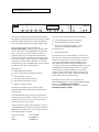
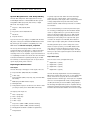
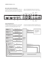
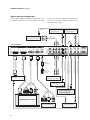
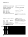
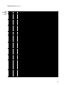
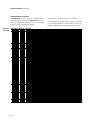
High Resolution
Video Scaling Engine
Product Guide
How to install, set up, and use your new DVDO product
English Version
O LL O
OG I E
B YB YA A
NN
CC
HH
O OR R B BAAYY TTEECC HH NN O
E SS
1
High Resolution
Video Scaling Engine
Product Guide
BY
BY
A N C H O R
A N C H O R
B AY
B AY
T E C H N O L O G I ES
T E C H N O L O G I ES
TABLE OF CONTENTS
Foreword
2
Remote Control Operation
16
Introduction
3
On-Screen Display (OSD)
16
Installation and Setup
4
Output Setup
16
16
System Requirements and Compatibility
4
Config
Input Signal Connections
4
Picture Control
16
Video Inputs
Input Adjust
16
Digital Audio Inputs
Menu
16
16
Rear View Connections
5
Zoom
Signal Flow Diagram
5
Pan
16
Typical System Configuration
6
Aspect Ratio Buttons
16
Output Signal Connections
7
Input Select Buttons
17
Power Supply Input
7
Power Button
17
Display Input Connectors
7
Info
17
HD15 (VGA-type) Connector
Curtain
17
Component (YPbPr) Input with RCA Jacks
Test Patterns
17
BNC Connectors
Technical Specifications
19
DVI Digital Video Input
Safety Information
20
Warranty
21
Acknowledgements
21
Displays and Controls
Initial Set-Up
8
8
Analog Component Output (YPbPr)
Analog RGB Output
DVI Output
Power/Standby Control
9
▲, ▼, and Enter/Exit Control
9
Output Control
9
Formats
10
Input Select Control
10
Input Aspect Ratio Control
11
Picture Control
11
Saved Settings for Individual Inputs
11
Audio Operation
12
From the Front Panel
From the On-Screen Display (OSD)
Input Adjust Control
12
Configuration Control
14
Customizing the Output Video Timing
for your Display
15
FOREWORD
Welcome to the family of DVDO product owners! Anchor Bay Technologies
is proud and pleased to return this truly great brand name to the marketplace
for video technology users around the globe. It is our pleasure to bring
you the iScan HD Video Processor, which we are sure will deliver years of
reliable performance.
First, a bit of history about our company. Anchor Bay Technologies is
composed of the former founding team of DVDO Inc. We are the original
creators of the first DVDO iScan™Plus Progressive Scan Display Interface,
which revolutionized the home theater video processor market starting in
1999. In July 2000, Silicon Image acquired DVDO Inc. and the iScan product
line. After that, Silicon Image introduced and marketed new iScan products,
including the iScan Plus v2, the iScan Pro, and most recently the iScan
Ultra. All of these products have met with universal critical acclaim from
reviewers and customers alike. Also, all of these products were designed by
the original creators of the DVDO iScan. In April 2003, Anchor Bay
Technologies Inc., with the original DVDO founders as the management team
of the new company, reacquired the iScan™ Video Processor product line
and the DVDO® brand name from Silicon Image. Today, we continue to sell
the iScan product line, and with the new iScan™ HD we are introducing
the first of many new DVDO-branded products.
Thanks again for your purchase of a DVDO-branded product. We look forward
to helping you in any way that we can. Should you need assistance you can
contact us via email or via our toll-free support line. And remember...
DVDO by Anchor Bay Technologies still stands for the highest performance,
the best value, and the best customer support.
It all adds up to digital video done outrageously!
The Anchor Bay Technologies Team
Campbell, California, USA
March 2004
2
INTRODUCTION
High Resolution Video Scaling Engine by Anchor Bay Technologies
Analog/Digital
Format/Resolution
Input
Select
Input
Aspect
Ratio
Picture
Control
Input
Adjust
Aspect Ratio
Configuration
Enter/Exit
Thank you for purchasing the iScan HD High Resolution Video
Scaling Engine, featuring video-processing technology as created
by the Anchor Bay Technologies team. This product delivers a
level of video quality among the very highest available today.
We are especially pleased to bring you ABT’s new
Precision Video Scaling™ technology. This technology enables
precision upconversion of all Standard Definition (480i, 480p,
576i, or 576p) video sources and content to the native or
optimum resolution of your display, delivering best-in-class
front-of-screen performance. Available output resolutions span
from 480p all the way to 1080p, including the standard HDTV
resolutions of 720p and 1080i. In addition to our own video
scaling technology, new to the DVDO product line, the iScan HD
also offers a host of other innovative features.
Among these are:
䊳
flexible Digital Audio switching
䊳
precision audio/video time-delay synchronization
䊳
improved timebase correction
䊳
fully programmable framerate conversion
䊳
input and output aspect ratio controls
䊳
flexible zoom and pan controls
The Technical Specifications section at the end of this
Product Guide summarizes the key features and performance
of the iScan HD.
Sync Type
Colorspace
Output
Setup
On/Remote
Standby
Power
Framelock
Adjust
Display Profile
The carton of your iScan HD should contain the following:
䊳
iScan HD High Resolution Video Scaling Engine
䊳
Universal 6V@5A AC to DC power converter
䊳
US power cord (international customers - please
consult your local Authorized DVDO Reseller)
䊳
Remote control
䊳
iScan HD Product Guide
The iScan HD uses a 15-pin HD15 VGA-type connector and a
DVI connector to provide video output signals. You will need to
purchase an output cable to connect one of these outputs to
your projector, HD-compatible TV, Plasma display panel, or
other display device. Different displays have different input
connectors, so please check your display specifications to ensure
compatibility. Even though the HD15 connector is commonly
used on personal computers for RGB video, the iScan HD is
capable of outputting either RGB or YPbPr (Component) video
formats from this connector. This is explained in detail in the
Output Control section of this Product Guide.
Both input and output cables can be supplied by your
Authorized DVDO Reseller. To find your nearest Authorized DVDO
Reseller, go to www.dvdo.com/res/index.html
You can also find a wide selection of cables on our website at
www.dvdo.com/pro/pro_acc.html
This Product Guide will help you set up your new iScan HD,
and will also give you information on how to match it to your
display, as well as how to connect it to and use it with the
rest of the components in your system.
Should you have any questions during the setup or operation
of this DVDO product, you should first contact your Authorized
DVDO Reseller for assistance. You can also contact Anchor Bay
Technologies directly for assistance:
Toll-Free (in the USA)
Email
Website
1.866.423.DVDO
[email protected]
www.DVDO.com
3
INSTALLATION AND SET-UP
System Requirements and Compatibility
The iScan HD is designed to drive displays that can accept
an ATSC Digital Television or VESA-standard PC video signal in
analog RGB or YPbPr (Component) video format, or digital
DVI format. Such displays include:
䊳
Projectors – DLP, LCD, CRT, D-ILA
䊳
HDTVs
䊳
Progressive scan and multimedia TVs
䊳
Plasma TVs
䊳
Computer monitors
If you are not sure if your display is compatible with the iScan
HD, please contact your local Authorized DVDO Reseller. Anchor
Bay Technologies also maintains a compatibility list on the
DVDO website at www.dvdo.com/faq/faq_compat.html
This list only shows the display models for which we have
received information from field testers, or that we have tested
directly in our labs. If your display is not listed, it does not
necessarily mean it is not compatible, it just means that there is
no compatibility information for it at this time. This information
is the latest available and is updated periodically as new data
are received by our Technical Support team. To inquire about a
specific display model, please contact us.
Input Signal Connections
Video Inputs
The iScan HD accepts several types of video signals. These are:
䊳
Composite Video (CVBS; NTSC, PAL, and SECAM)
䊳
S-Video (Y/C)
䊳
Component Video (YPbPr; 480i, 480p, 720p, and 1080i ATSC
DTV formats)
䊳
RGBS (European SCART interface output)
䊳
DVI Digital Video
䊳
Analog Passthru input (for use with sources for which no video
processing is desired, such as native HDTV or PC formats)
The eight (8) video inputs are:
䊳
Video 1 (Composite)
䊳
Video 2 (Composite)
䊳
S-Video 1 (Y/C)
䊳
S-Video 2 (Y/C)
䊳
Component 1 (YPbPr or RGBS, automatic switching)
䊳
Component 2 (YPbPr or RGBS, automatic switching)
䊳
DVI (Digital Visual Interface standard for digital video)
䊳
Analog Passthru
4
In general, Composite video delivers the lowest final image
quality due to the combined nature of the Y (luminance)
and C (chrominance) video signals. There is a large improvement
in image quality between Composite and S-Video, but the
difference between S-Video and Component video is somewhat
less noticeable.
It is recommended that you use the Component video inputs
for connecting your DVD player and direct broadcast satellite
receiver (or digital cable box) to your iScan HD, since these
tend to be the highest quality video sources. VCRs generally
have the lowest image quality, and therefore will not be as
affected by the lower quality of the composite video signal
connection. An exception are S-VHS VCRs, which feature an
S-Video output of higher quality than conventional VHS VCRs.
The Analog Passthru input is used for analog video sources
that do not require processing, such as HDTV satellite broadcasts, video sources that are already in progressive format
or HD formats, or personal computer video output. This input
allows you to pass these signals through the iScan HD without
any video processing.
Digital Audio Inputs
There are a total of four (4) Digital Audio inputs:
䊳
Digital Audio 1 (coaxial)
䊳
Digital Audio 2 (coaxial)
䊳
Digital Audio 3 (optical)
䊳
Digital Audio 4 (optical)
The iScan HD accepts Digital Audio sourced from DVD players,
DBS receivers, digital cable set-top boxes, or other digital audio
devices. There are four (4) inputs; two each of Coaxial and
Optical transmission interface types. These inputs are compatible
with most consumer Digital Audio formats, including CD-Audio
(44.1kHz/16 bit linear pulsecode modulation), Dolby Digital, or
DTS. Generally, the Digital Audio inputs are compatible with any
format with a sampling frequency between 44 kHz and 96 kHz,
and with a data word structure between 16 and 24 bits in length.
Installation and Set-Up (continued)
iScan Rear View Connections
The following figure shows the input and output connector complement on the rear panel of the iScan HD. There are a total of
eight (8) Video inputs, two Video outputs, four (4) Digital Audio
inputs, and two Digital Audio outputs. Also shown are the
DC Power Input and the RS-232 serial port computer interface.
Sync 2
DVI Input
DVI Output
Analog
Output
Analog
Passthru
Power
Sync 1
Digital
Audio
Component 2
Composite Out 2
(YPbPr or RGB) S-Video 2 Video 2
(optical)
Component 1 S-Video 1 Composite Digital
(YPbPr or RGB)
Video 1
Audio
Out 1
(coaxial)
Digital Audio
Inputs
(optical)
4
3
1
2
Digital Audio
Inputs
(coaxial)
Serial Port
Signal Flow Diagram
The following diagram shows a typical way to use the iScan HD
in a system. The following figure depicts a system where the
iScan HD is used as the primary video switcher or “hub”.
The iScan HD is usually placed between the display device and
any video sources and acts as the source switch for the display.
Component Video 1 (YPbPr)
DVD Player or other
Component video source
with Digital Audio output
Digital Audio 1 (Coaxial)
Analog video output
or
Component Video 2 (YPbPr)
DVD Player or other
Component video source
with Digital Audio output
DVI-D digital video output
Digital Audio 4 (Optical)
Projector, HD-Ready TV,
Plasma display panel,
computer monitor,
or other SD/HD capable
display device
S-Video 1
DBS Receiver, Game Console
or other S-Video source
with Digital Audio output
Digital Audio 2 (Coaxial)
S-Video 2
DVD Player or other
S-Video source
with Digital Audio output
Digital Audio 3 (Optical)
iScan HD
Video
Processor/
Scaler
Video 1 (Composite)
VCR or other
Composite video source
Laserdisc Player or other
Composite video source
Video 2 (Composite)
HD-DBS Receiver, PC,
or other High Definition
video source
HD-DBS Receiver, PC,
or other High Definition
video source
Digital Audio Out 2 (Optical)
Digital Audio Out 1 (Coaxial)
Analog Pass-Thru
DVI
Digital Audio Inputs
Analog Audio (L/R)
Analog
Audio
Inputs
AV Preamplifier/Processor or AV Receiver
5
Installation and Set-Up (continued)
Typical System Configuration
The iScan HD is usually placed between the display device and
any video sources and acts as the source switch for the display.
Shown in this connection diagram are eight audio/video
sources, four of which have digital audio outputs along
with analog video outputs.
Video Game or Other
Composite Video Source
Video Cable
Rear View of iScan HD
YPbPr
Set-top box or other
DVI source
Component Video Source
(480i, 480p, 720p, or 1080i)
C
BN
or
A
RC
5x
VCR or Other
S-Video Source
3x
HD15
3x
5x
Progressively Scanned TV or Projector
or
or
A
RC
BN
C
DVI-D
or
HD15
HD Satellite TV Tuner, PC, or
Progressive-Scan DVD Player
6
Audio/Video Preamplifier/
Processor or AV Receiver
Video Game or Other
Composite Video Source
Digital Audio Cable (Coaxial)
Digital Audio Cable (Coaxial)
Digital Audio Cable (Coaxial)
Composite Video Cable
AC Mains
(100-240 VAC
50/60 Hz)
S-Video Cable
Component
Video Cable
HD Video
Universal
Power Adaptor
Digital Audio Cable (Optical)
DVI-D
HD15
HD Video
DVI-D or DVI-I Interface Cable
Interface Cable
DVI-D or DVI-I
HD15
DVI-D
DVI-D
Composite Video Cable
S-Video Cable
Component
YPbPr
Component Video Source
(480i, 480p, 720p, or 1080i)
Set-Top Box or
Other S-Video Source
Digital Audio Cable (Optical)
Digital Audio Cable
(Optical)
Installation and Set-Up (continued)
Output Signal Connections
There are two output connectors on the back of the iScan HD:
1) 15-pin HD15 Analog Output (VGA-type)
2) DVI Digital Video Output
Many progressive-scan TVs available today have a VGA or
Component input for 480p/576p input signals and this is used
with the 15-pin HD15 connection on the iScan HD. Newer
digital TVs may also provide a Digital Visual Interface (DVI)
digital video input that allows for video to be transmitted in
digital format to the display. Use the DVI output of the iScan
HD to interface to displays equipped with this interface.
Power Supply Input
The iScan HD comes with a 6V@5A AC to DC converter power
supply, which accepts 100-240 VAC at 50/60Hz. Connect this to
the ‘DC In’ port on the back of the iScan HD. IMPORTANT: Use
only the power supply that came with your iScan HD, or a
replacement procured directly from Anchor Bay Technologies.
Display Input Connectors
There are a number of different connectors used on displays,
but the most common are the 15-pin HD15 (VGA-type), BNC,
and RCA connectors. Newer displays may also have the DVI
digital video input connector as well, as described above.
HD15 (VGA-type) Connector
The VGA cable/connector is commonly used
in PC applications and should be readily
available in any computer or electronics store.
You will want to make sure that you select a
well-shielded high-quality cable to reduce
reflections and other degrading effects on the video signal.
Most multimedia TVs/displays with progressive scan capability
will have an input of this type and should be able to accept
both YUV and RGB color formats.
Component (YPbPr ) Input with RCA Jacks
Most displays with Component video inputs will
have three RCA jacks for YPbPr video signal
connections. To connect to these displays, you
can use the DVDO Precision HD15 to 3-RCA
Component Video Cable (ABT part number 112001-01). You can find it on our website at
www.dvdo.com/pro/pro_acc.html
Connect the three signal lines to the corresponding color RCA
jacks on your display. There is no sync connection required
for this type of input since the sync signals are embedded in
the ‘Y’ signal line (which is carried on the green wire).
BNC Connectors
Many home theater projectors do not have an
HD15 connector, in which case you can use an
adapter cable to convert from VGA to the BNC
connectors used on the projector. These adapter
cables are readily available through most home
theater retailers and have a VGA connector on
one end and BNC connectors on the other.
The BNC end of the cable will usually have 5 connectors
(labeled R, G, B, Hsync, and Vsync), although not all will
necessarily be needed for every display. Please refer to your
display’s specifications to determine which input signals it
requires. If your display device accepts Component video
(YPbPr), then you will not need the H and V lines since these
sync signals are actually part of the information in the ‘Y’
signal. If your display device requires RGBS, then this is
Composite Sync, which is sent on the H (white/gray) line.
Displays that require RGBHV will require all 5 BNC connectors.
Hsync is sent on the white/gray wire, and Vsync is sent on
the yellow/black wire.
Below is a table showing the signal mappings for each wire of
the BNC cable.
Input Type
Wire Color
RGB/HV
RGBS
YPbPr
(Component)
Red
R (Red)
R (Red)
Pr
Green
G (Green)
G (Green)
Y
Y
Blue
B (Blue)
B (Blue)
Pb
V
White or Gray
H sync
Composite sync No Connect
H sync
Yellow or Black
V sync
No Connect
V sync
No Connect
YUV/HS
U
DVI Digital Video Input
The DVI digital video connector is
used on many newer digital TVs and
is similar in functionality to the analog
VGA connector except that the video signal is transmitted
digitally from the iScan HD to the display device. This provides
the highest possible quality video image from the iScan HD
to the display. Once you have the iScan HD connected to your
home theater system, there are several configuration parameters
that you may adjust to output the proper signal format
for your display device and optimize the image to your
personal preferences.
7
DISPLAYS AND CONTROLS
Front Panel Display (FPD)
Output Setup Indicators
High Resolution Video Scaling Engine by Anchor Bay Technologies
Analog/Digital
Format/Resolution
Input
Select
Input
Aspect
Ratio
Picture
Control
Input
Adjust
Aspect Ratio
Configuration
Enter/Exit
Initial Set-Up
Once you have installed the iScan HD into your system, it must
be properly configured for the display device being driven. The
iScan HD is shipped from the factory with the following preset
default settings:
Down
Output
Setup
On/Remote
Standby
Power
Framelock
Adjust
Front of Unit
Sync Type
Colorspace
Display Profile
On/Standby
Up
2. Connect the other end of cable to the display device’s
RGB input jacks
3. Change the sync type of the iScan HD from bi-level sync to
separate HSync and VSync (H+V).
䊳
Push the Output Control button until Sync Type is
selected and the front panel display (FPD) shows ‘SYNC’
䊳
Input Select is set to AUTO, to automatically detect
an active input in a pre-configured priority
䊳
䊳
Press the ▼ button to see the sync type ‘BI’
(for bi-level sync)
The Analog Video output is selected
䊳
䊳
Press the ▼ button to go to the next sync type
The output format is set to ATSC (DTV) 480p, with YPbPr
colorspace and bilevel sync on the luma signal
䊳
Repeat this step to select the desired sync type
䊳
Push the Output Control button to exit the menu
Use either the remote control or the front panel controls to
perform the initial setup of the iScan’s output. The front panel
buttons are used to perform the initial setup described below.
There are three ways to connect the iScan HD output to a
display device. They are Analog Component, Analog RGB,
and DVI output.
Analog Component Output (YPbPr)
Typically, an HD15 (VGA-type) to 3-RCA connector cable is
needed for this configuration.
4. Change the colorspace from Component YPbPr to RGB
䊳
Push the Output Control button again. The FPD shows
‘COLR’ for colorspace selection
䊳
Press the ▼ button. The FPD shows ‘YUV’, which is the
current colorspace (Component YPbPr).
䊳
Press ▼ button again to select the ‘RGB’ colorspace.
䊳
Push the Output Control button to exit the menu.
You have now configured the iScan HD to output 480p in RGB
colorspace, with separate Hsync and Vsync signals.
1. Connect the VGA end to the iScan’s Analog Video output
2. Connect the 3 RCA connectors into the display device’s
Component Video input
3. Select the corresponding input on the display device
You should get a picture. Now you are ready to set up your
display further with the remote control unit using the iScan
HD’s on-screen display (OSD).
Note: The actions above result in the iScan HD always using
RGB for colorspace and H+V for Sync type regardless of format
selection.
DVI Output
1. Connect the DVI cable from the DVI output of your iScan HD
to the display device.
2. Push the Output Control button once
Note: the iScan HD features a set of predefined formats that
you can choose from. These formats include colorspace and sync
signal type as shown in the Format table on page 10. If you
choose a format that requires RGB colorspace and H+V sync, you
need to manually change the colorspace to YPbPr and sync type
to bi-level or tri-level sync. Once this is done, future format
selections will always use the same colorspace and sync type
that you reset the unit to.
6. You should now see a picture on your display device.
Analog RGB Output
You have now configured the iScan HD to output 480p on DVI.
Typically either a VGA to VGA, a VGA to 5-BNC, or a VGA to
5-RCA cable is needed for this configuration.
Note: Since the DVI video format is defined as RGB with
separate H+V sync signals, there is no need to modify colorspace
or sync type when using the DVI output. The format selection by
default is always sets to RGB with H+V Sync.
1. Connect the HD15 (VGA) end to the iScan’s Analog output
8
3. The FPD will show ‘A/D’ for analog or digital video output
choices
4. Push the ▼ button once. The FPD will now display ‘ANLG’
for Analog Video output.
5. Push ▼ button again. The FPD will now show ‘DVIV’ for DVI
with Video levels.
Displays and Controls (continued)
Power/Standby Control
Output Control
Pushing the Power button toggles the system between two states:
active and standby. There is a tricolor LED that is next to the
Power button. In Standby mode, the LED is illuminated red.
When the system is active, the LED color indicates:
blue (the system is processing the input signal); green (the
system is passing through the signal without processing).
The Output Control settings allow you to configure the output
of the iScan HD to match the requirements of the specific type
and model of display device being driven.
▲, ▼, and Enter/Exit Controls
These buttons allow you to navigate the menus and submenus.
Their functions are dependent on the specific function selected.
Output
Control
Menu
Pushing the Output Control button once shows the current output control function. You can cycle through the functions by pushing this button repeatedly. There is an LED corresponding to each
function. This helps you to set up the output without an image
on the display. The table below shows the available functions.
The FPD (front panel display) and the OSD (on-screen display)
will turn on when the Output Control button is pressed. The
Output Control indicators, FPD, and OSD will turn off automatically after 30 seconds.
Output Control
FPD shows
Description
Analog or Digital
Output
A/D
Pushing the ▼ button shows the current output type. Pushing the ▼ button again selects the next item on the
list shown below. You can also use the ▲ button to cycle through the output types.
VGA Analog Output (VGA-type HD15)
DVIV DVI output for displays that require video signal levels.
DVIP DVI output for displays that require PC signal levels.
Output Format
FMT
Output
Aspect Ratio
O_AR
Pushing the ▼ shows the current output format. Pushing the ▼ button again shows the next item on the list
shown below. The format is not selected until the Enter/Exit button is pressed. Pressing the Enter/Exit button again
selects the output timing controls, discussed in the Output Timing section.
Sets the display output aspect ratio. Press the ▲ or ▼ button first to show the current aspect ratio. Press the
same button again to move to the next aspect ratio. Currently two aspect ratios are supported: 16:9 and 4:3.
More aspect ratio options will be supported in future software releases.
Sync Type
SYNC
Note: the Sync Type function is
disabled with DVI output, because
the DVI standard requires separate
Hsync and Vsync
Color Space
COLR
Frame Rate
Conversion
FRC
Sets the synchronization signal type of the output format. Press the ▲ or ▼ button first to show the current sync
type. Press the same button again to move to the next sync type. Currently 4 sync types are supported:
BI
bi-level sync on green/luma (in RGB colorspace, sync is also present on red and blue signals)
TRI tri-level sync on green/luma (in RGB colorspace, sync is also present on red and blue signals)
CSYN Composite Sync (on the Hsync pin of the HD15 output connector)
H+V Separate Hsync and Vsync signal
Sets the colorspace of the output format. Press the ▲ or ▼ first to show the current colorspace. Press the same
button again to select the alternate colorspace. Two colorspaces are supported: YPbPr (default) and RGB.
Enables frame rate conversion. There are two sets of controls, one for 50Hz input sources and one for 60Hz input
sources. For 50Hz sources, if the original source material is progressive at 25Hz (uses 2:2 pulldown), the output
frame rate can be source locked at either 50Hz or 75Hz. The 75Hz setting will repeat each of the original 25Hz
frames 3 times. You can also set the output frame rate to a specific value (unlocked mode). For 60Hz sources, if
the original source material is progressive at 24Hz (uses 3:2 pulldown), the output frame can be source locked to
either 48Hz, 60Hz or 72Hz. The 48Hz setting will repeat each original 24Hz frame 2 times, while the 72Hz setting
will repeat each frame 3 times. As with 50Hz sources, you can also set the output frame rate to a specific value
(unlocked mode).
Press the ▲ or ▼ button once to see the current input rate.
Press the same button again to switch input rate.
50 - > 50Hz input sources
60 - > 60Hz input sources
Press the Enter/Exit button to select the input frame rate and change the output frame rate settings. Select the
desired output frame rate setting by using the ▲ or ▼ button.
For 50 Hz
50 L
75 L
UNLK
input sources, the available settings are:
source locked 50Hz
source locked 75Hz
unlocked
For 60 Hz input sources, the available settings are:
48 L source locked 48Hz
60 L source locked 60Hz
72 L source locked 72Hz
UNLK unlocked
If UNLK is chosen, press the Enter/Exit button again to specify the desired output frame rate.
Use the ▲ or ▼ button to increase or decrease the frame rate.
Press the Output Select button again to exit the menu and complete the output frame rate conversion setting.
Display Profile
DISP
currently not available
9
Displays and Controls (continued)
Formats
Preset Formats and Characteristics for Analog Video Output
For DVI output, the Sync type is always separate Hsync and
Vsync, and the colorspace is always RGB. For analog output,
the factory default format is 480p as shown in the table.
Once you override the sync and colorspace selection, future
format selections will not affect the sync type and colorspace.
Horizontal Vertical
Scan FPD
Resolution Resolution Type* shows
Sync
Sync
Signal Signal
Line(s) Type
Colorspace
720
480
P
480P
Y
Bi-level
YPbPr
1920
540
P
540P
Y
Tri-level
YPbPr
720
576
P
576P
Y
Bi-level
YPbPr
1280
720
P
720P
Y
Tri-level
YPbPr
1920
1080
I
108I
Y
Tri-level
YPbPr
1920
1080
P
108P
Y
Tri-level
YPbPr
640
480
P
VGA
H+V
-
RGB
800
600
P
SVGA
H+V
-
RGB
1024
768
P
XGA
H+V
-
RGB
1280
1024
P
SXGA
H+V
-
RGB
852
480
P
PLA1
H+V
-
RGB
852
576
P
PLA2
H+V
-
RGB
1366
768
P
PLA3
H+V
-
RGB
1280
768
P
PLA4
H+V
-
RGB
1024
1024
P
PLA5
H+V
-
RGB
1024
852
P
PLA6
H+V
-
RGB
1024
576
P
DLP1
H+V
-
RGB
848
600
P
DLP2
H+V
-
RGB
1365
1024
P
DIL1
H+V
-
RGB
1400
1050
P
DIL2
H+V
-
RGB
1400
788
P
DIL3
H+V
-
RGB
960
540
P
LCD1
H+V
-
RGB
1280
960
P
QUA1
H+V
-
RGB
1440
960
P
QUA2
H+V
-
RGB
1440
1152
P
QUA3
H+V
-
RGB
Input Select Control
The Input Select control enables you to select one of the
eight (8) inputs of the iScan HD. When this button is first
pressed, the front panel display (FPD) shows the current
selected input. When this button is pressed again, it selects
the next input on the list. When you’ve reached the last input,
pressing the button again selects the first input on the list
and the process repeats. You can also cycle through the inputs
by pushing this button once and then pressing the ▼ or ▲
arrow buttons.
The table below shows the list of inputs in the order that they
are cycled through using the Input Select button. The location
of the connectors is shown on page 5.
The Input Select indicator (LED), the front panel display (FPD)
and the on-screen display (OSD) will turn on when the button
is pressed. The indicator will glow green if the selected input is
active and red if it is not active.
The Input Select LED, FPD and OSD will turn off automatically
after 30 seconds. If the input is not active, the LED will remain
illuminated red.
Input
Select
Control
Input
FPD shows
* P = progressive; I = interlace
Description
Video 1
VID1
Composite Video 1
Video 2
VID2
Composite Video 2
S-Video 1
SVD1
S-Video 1
S-Video 2
SVD2
S-Video 2
Component 1 /
RGBS 1
COM1
Component Video 1 - This input accepts either a YPbPr or RGBS signal. The input is configured for YPbPr by default,
and switches to RGB when a connector is plugged into the Sync 1 input. This input will accept 480i, 480p, 576i and
576p formats. All other formats will be passed through to the analog output unchanged.
Component 2 /
RGBS 2
COM2
Component Video 2 - This input accepts either a YPbPr or RGBS signal. The input is configured for YPbPr by default,
and switches to RGB when a connector is plugged into the Sync 2 input. This input will accept 480i, 480p, 576i and
576p formats. All other formats will be passed through to the analog output unchanged.
Analog Passthru
PASS
Analog Passthru is selected. This signal is passed through to the Analog Output unprocessed.
DVI
DVI
DVI Input - The DVI input is automatically scaled by the iScan HD if the content is not copy-protected and the
resolution is 480P or 576P. Otherwise, the DVI input is passed through to the DVI output unprocessed.
Automatic
AUTO
Input Selection
Automatic active input selection - Automatically selects an input from among all currently active inputs based on an
internal priority list. The factory default list is shown below from highest to lowest priority. You can assign different
priorities to the iScan HD’s video inputs using the Configuration control then selecting AutoSource (IPSL).
1234-
10
Component / RGBS 1
Component / RGBS 2
S-Video 1
S-Video 2
5678-
Video 1
Video 2
DVI
Analog Passthru
Note: The DVI input and Analog Passthru functionality
is dependent on which output is selected.
Displays and Controls (continued)
Input Aspect Ratio Control
The Input Aspect Ratio control selects the aspect ratio for
the current input signal. The iScan HD will automatically convert
from the selected input aspect ratio to the selected output
aspect ratio.
Input Aspect
Ratio
4:3
Letterbox
16:9
Preset
FPD shows Description
4/3
LBX
16/9
PRST
Pushing the Input Aspect Ratio button once shows the
current input aspect ratio. You can cycle through the available
input aspect ratios by pushing this button again or by using
the ▼ or ▲ button.
The Input Aspect Ratio LED, the FPD (front panel display) and
the OSD (on-screen display) will all illuminate when the button
is pressed. The LED, FPD, and OSD will turn off automatically
after 30 seconds.
Picture Control
Pushing the Picture Control button once shows the current
picture control function. You can cycle through the available
functions by pushing this button repeatedly.
For each function, pushing the ▲ or ▼ button once shows the
current setting. Pushing either of these buttons again will
Picture
Control
Menu
Input aspect ratio is 4:3
Input aspect ratio is 4:3 letterboxed
Input aspect ratio is 16:9
The PRST button is set to 16:9 input
aspect ratio by default. It stores the latest custom aspect ratio settings that you
have defined. This is unique to each
input. A custom aspect ratio is defined as
a standard aspect ratio (16:9, LBX or 4:3)
that has been modified with the Zoom
and Pan controls. If no custom aspect
ratio is defined, it will remain 16:9
increase or decrease the setting. Push the Enter/Exit button to
exit the menu and go back to the picture control selection.
The table below shows the available Picture Controls.
The Picture Control LED, the FPD (front panel display) and the
OSD (on-screen display) will turn on when the button is pressed.
The LED, FPD, and OSD will turn off automatically after 30 seconds.
Picture Controls
FPD shows
Description
Brightness
BRT
Adjusts the brightness of the selected input signal. Default setting is 0 (midrange).
Contrast
CNT
Adjusts the contrast of the selected input signal. Default setting is 0 (midrange).
Saturation
SAT
Adjusts the color saturation setting of the selected input signal. Default setting is 0 (midrange).
Hue
HUE
Adjusts the hue (tint) of the selected input signal. Default setting is 0 (midrange).
Note: This control has no effect on Component or PAL format input signals.
Sharpness
SHRP
Adjusts the sharpness of the selected input signal. Default setting is 0 (midrange).
Note: This control has no effect on Component Video input signals.
Sharpness
(Component)
SHRC
Adjusts the sharpness of the selected input signal. Default is Off.
Note: This control has no effect on Composite video or S-Video input signals.
Y/C Delay
YC D
Adjusts the Y/C differential Delay of the selected input signal. Default is 0.
Chroma Filter
(Auto CUE-C)
CUEC
Auto CUE-C. This feature removes chroma upsampling errors (CUE) found in some video sources which have been
MPEG encoded and then improperly decoded. There are three available settings:
OFF: No chroma filtering. Use this setting if the source does not have a CUE problem.
ON: Chroma filtering is always on. Use this setting if the source is known to have a CUE problem.
AUTO: Automatic chroma error detection and correction. Use this setting if it is not known if a source has a CUE
problem. This setting is also recommended for all digital sources which use MPEG2 decoders (DVD players, digital
satellite receivers, etc.) as it will also detect and correct chroma errors created by all sources of this type when
the source is encoded as interlaced (also sometimes called Interlaced Chroma Problem, or ICP).
Saved Settings for Individual Inputs
The iScan HD saves the settings listed to the right for each
individual video input, where applicable. There are no saved
settings for the Analog Passthru input.
Picture Control
Brightness
Contrast
Saturation
Hue
Sharpness
Y/C Delay
Chroma Filter
Input Aspect Ratio
11
Displays and Controls (continued)
Audio Operation
From the Front Panel
The iScan HD features an audio delay function to exactly match
the video delay incurred by the video processing. The iScan HD
accepts four digital audio inputs: two coaxial (Audio 1, 2) and
two optical (Audio 3 and 4) inputs. The location of the audio
inputs are shown on back panel diagrams earlier in this document. The factory default audio assignment is:
1. Select Video Input as described in Input Select Control,
page 10.
Digital Audio 1 (coaxial) <-> Component 1
Digital Audio 2 (coaxial) <-> S-Video 1
Digital Audio 3 (optical) <-> S-Video 2
Digital Audio 4 (optical) <-> Component 2
You can assign a Digital Audio input to each Video input in the
following manner:
2. Use the Configuration button to select the Digital Audio
input assignment function (ASEL) as described above.
3. Select the next video input. Repeat step 2.
From the On-Screen Display (OSD) using the Remote Control
1. Select a Video Input on the remote control.
2. Select Audio Input 1, 2, 3, 4 or Off from the
‘Configuration/Audio Input’ menu.
3. Select the next video input. Repeat step 2.
Digital Audio Outputs
There are two digital audio outputs, one coaxial and one optical.
Both are active at the same time, with the selected input Digital
Audio stream.
Input Adjust Control
Pushing the Input Adjust button once shows the current input
adjustment function. You can cycle through the available functions by pushing this button repeatedly.
The currently available input adjust functions are
- Zoom
- Overscan
- Audio input control
- Pan
- DVI input control - AV Lip Sync
- Borders
- VCR mode
- Border level
- Film mode
Other functions will be added in future software releases.
For the Zoom, Pan and Borders functions, pushing the ▼ or ▲
button selects the two control settings available: horizontal and
vertical. Push the Enter/Exit button to adjust each setting.
Input
Adjustment
Menu
- Push ▲ and ▼ to increase or decrease the setting.
- Push Enter/Exit again to exit this mode
Note: The Zoom and Pan function are applied to the input
signal, not the output. This is an important consideration,
especially for the Pan function. For example: If a full frame image
is not zoomed more than 100%, there is nothing to pan.
However, if part of the image is not on the screen, then the
Pan function will work.
The Input Adjust LED, the FPD (front panel display) and the OSD
(on-screen display) will turn on when the button is pressed. The
LED, FPD, OSD will turn off automatically after 30 seconds.
Input Adjust FPD shows Description
Zoom
Pan
ZOOM
The Zoom function zooms in on or magnifies the image on your display. The minimum zoom is 100%, (no zooming)
while the maximum zoom is 200% (zoom magnification factor of 2X).
HOR
Horizontal Zoom control. Pushing the Enter/Exit button shows the current Zoom setting.
Pushing ▲ and ▼ button increases or decreases the zooming factor.
VERT
Vertical Zoom control. Pushing the Enter/Exit button shows the current Zoom setting.
Pushing ▲ and ▼ button increases or decreases the zooming factor.
PAN
The Pan function allows the image to be shifted up, down, left and right. Note that the Pan function can only be used
after the image has been zoomed to any value greater than 100%.
HOR
Horizontal Pan control. Pushing the Enter/Exit button shows the current Pan setting. Pushing the ▲ button pans to the
right. Pushing the ▼ button pans to the left.
VERT
Vertical Pan control. Pushing the Enter/Exit button shows the current Pan setting. Pushing the Enter/Exit button shows the
current Pan setting. Pushing the ▲ button pans up. Pushing the ▼ button pans the image down.
(Input Adjustments Menu table continued on next page)
12
Displays and Controls (continued)
Input
Adjustment
Menu
(continued)
Input Adjust FPD shows Description
Borders
BORD
The Borders function allows you to add horizontal and/or vertical borders around the image. These borders will obscure
part of the input image. Certain input-to-output aspect ratios already result in left/right or top/bottom border being
added. This control allows the system-generated borders to be extended, or for borders to be added when none exist. As
the borders are adjusted (see below) the iScan will temporarily increase the gray level of the borders so that they are visible during the adjustment process. The level will return to normal after the adjustment has ceased.
HOR
Horizontal Border control. Pushing the ▲ button moves the left and right borders towards the middle of the image,
increasing the border width and cutting off the sides of the input image. Pushing the ▼ button moves the left and right
borders away from the image and decreases their width. If there are system-generated left/right borders already present
(e.g, when the input aspect ratio is 4:3 and the output aspect ratio is 16:9), the border width cannot be decreased
beyond the base width created by the aspect ratio conversion.
VERT
Vertical Border control. Pushing the ▲ button moves the top and bottom borders towards the middle of the image,
increasing the border height and cutting off the sides of the input image. Pushing the ▼ button moves the top and bottom borders away from the image and decreases their height. If there are system-generated top/bottom borders already
present (e.g, when the input aspect ratio is 16:9 and the output aspect ratio is 4:3), the border height cannot be
decreased beyond the base height created by the aspect ratio conversion.
Border level
BLEV
The Border level can be also be adjusted to prevent burn-in with some displays. The border level setting is global i.e.
there is only one border level setting for the system. To adjust border level, push the ▼ or ▲ button. The current level is
shown. The default value is ‘0’. Pushing the ▼ or ▲ button decreases or increases the border level.
Overscan
SCAN
The Overscan function scales the input image proportionally in both vertical and horizontal dimensions by the user-specified overscan factor. The purpose of Overscan is to remove unwanted image portions around the perimeter of the image.
The default overscan value is 0, which means 100% of the input image is shown. The maximum overscan value is 20
which means the input image scaled up by 120%. To adjust the overscan level, first push the ▼ or ▲ button. The current
level is shown. Pushing the ▼ or ▲ button then decreases or increases the amount of overscan. The Overscan value is
applied to all input aspect ratios and is independent of the Zoom value.
DVI Input
DVII
The DVI Input control function allows you to configure the DVI Input in ‘Auto’ mode or in ‘Passthru’-only mode.
AUTO: The system is set to process the incoming DVI signal. If the signal is 480p or 576p and not HDCP protected,
the system will process the image. Otherwise, the system will go into Passthru mode.
DPTH: In the Passthru-only mode, the system will always pass through the DVI signal. Pushing the
▼ or ▲ button shows the current setting. Pushing the same button again switches to the other setting.
VCR Mode
VCR
VCR Mode decouples the output timing completely from the input timing to ensure a stable output from the iScan HD for
VCR playback especially during trick-play modes (play forward, play reverse, still/pause). There are 3 modes:
ON: Output timing is decoupled from the input timing regardless of Frame Rate settings.
OFF: Output timing is dependent on Frame Rate settings.
AUTO: Turns on VCR Mode if a VCR source is detected.
Film Mode
FILM
Film Mode is designed to allow you to turn film mode off, which may be desirable in cases where the detection is not reliable. There are 2 modes - OFF and AUTO.
OFF: Turns off film detection in the deinterlacer. All video sources are treated as original video
AUTO: Source adaptive deinterlacing is on.
Audio Input
ASEL
This menu allows you to assign a Digital Audio input to the currently selected Video input. To assign the audio input to
another video input, push the ▼ button. The front panel display (FPD) will show the current setting.
Pushing the ▼ button again will assign the next audio input. The five settings are:
AUD 1
AUD 2
AUD 3
AUD 4
OFF
(When this control is set to OFF, the Digital Audio outputs are disabled when the corresponding video input is selected.)
AV Lip Sync
AVLS
iScan HD automatically delays the input audio to match the video processing delay. You can choose to increase or
decrease the audio delay by changing this setting. Pushing the ▲ or ▼ button first displays the current additional bias
delay setting (default 0). Use the ▲ or ▼ button to increase or decrease the delay in milliseconds.
Note: the total audio delay cannot be less than zero - i.e., the iScan cannot have negative audio delay. If you choose to
decrease the automatic delay setting by a certain amount - this value could be changed by the iScan in situations where the
iScan's calculated delay plus the specified additional delay will result in a value less than zero.
13
Displays and Controls (continued)
Configuration Control
The Configuration control provides access to additional important control functions. Pushing the Configuration button once
shows the currently selected function. You can cycle through the
functions by pushing this button repeatedly.
Configuration
Control Menu
The table below shows selections that can be controlled.
The Configuration LED, the FPD (front panel display) and the OSD
(on-screen display) will turn on when the button is pressed. The
LED, FPD, and OSD will turn off automatically after 30 seconds.
Configuration
AutoSource
(Auto Priority)
FPD shows
IPSL
Description
This menu allows you to assign different priorities to the video input’s automatic active video selection mode (AUTO in
Input Select menu). First select the video input, then change the priority of that input.
1- Press the ▼ button
2- The first video input VID1 is shown.
3- Press the Enter/Exit button to view the current priority of the selected input.
4- Press the ▲ or ▼ button to change the priority of the selected input
5- Press the Enter/Exit button again to complete the priority assignment.
6- Repeat Steps 1 through 5 to select the next video input and adjust the priority setting.
Auto Standby
STBY
The default setting is OFF, which means iScan HD will always be in Active mode regardless of the activity state of the
selected input. If Auto Standby is ON, iScan HD will go into Standby mode 30 seconds after the selected input becomes
inactive. To see the current setting, first press ▲ or ▼. Then press the same button again to change the setting.
Power LED
PLED
Allows you to configure the behavior of the Power LED.
Factory
Default
FCTD
OFF: Turns the Power LED off at all times
ON: Turns the Powe LED on. LED turns blue when the system is processing the an input signal. LED turns red in
standby mode. LED turns green in pass-through mode.
AUTO: LED turns off after approximately 30 seconds without user interaction.
Allows you to reset system settings to the factory default. First press either the ▲ or ▼ button. The FPD will show
‘NO’. Then press the same button to switch to ‘YES’. Confirm this selection by pressing the Enter/Exit button.
The default factory settings are:
Input Selection: Auto
Input Aspect Ratio: 16:9
Picture Controls: midrange (0)
Sharpness (Component): Off
Chroma Filter (CUEC): Off
Output Aspect Ratio: 16:9
1– Component 1
Output Resolution: 480P
2– Component 2
Component 1
- Audio
Sync: Sync on Y
3– S-Video 1
Component 2
- Audio
Output Color Space: YPbPr
4– S-Video 2
S-Video 1
- Audio
Output Type: Analog
5– Video 1
S-Video 2
- Audio
Auto Standby: Off
6– Video 2
Video 1
- Off
Frame Rate: 1:1 source-locked output
7– DVI
Video 2
- Off
User Mode: Normal
8– Analog Passthru
DVI
- Off
Video Input Priority Settings:
Analog Passthru - Off
Digital Audio Input Assignment:
1
4
2
3
Software
Update
SWUP
You can upgrade your iScan HD firmware using this command. First press the ▲ or ▼ button. The FPD will show ‘NO’.
Then press the same button to switch to ‘YES’. Confirm this selection by pressing the Enter/Exit button. Care must
be taken before performing a firmware upgrade. Make sure you really want to do this. Once the ‘YES’ selection is
confirmed, the FPD will show ‘LOAD’. If you change your mind, you can wait for about 5 minutes for the command
to be cancelled or you can power cycle the system by unplugging the DC Power input jack.
User Mode
USRM
The About Box
INFO
You have limited access to the output timing controls in ‘Normal’ mode. In ‘Advanced’ user mode, you have access
to the complete set of output timing controls. See the section entitled “Customizing the Output Video Timing for your
Display”. Push the ▼ button to see the current setting. The FPD will display either ‘NORM’ for normal or ‘ADV’ for
advanced user level. Pushing the ▼ button again selects the alternate mode.
Shows information about the system including Input Status, Output Status and System Version number.
Press the ▲ or ▼ button to activate.
14
Displays and Controls (continued)
Customizing the Output Video Timing
for your Display
The iScan HD allows you to customize its output timing for the
specific requirements of the display. Full output timing adjustment should be done only if you are very familiar with advanced
display setup. Caution: if you are not familiar with display
setup, you should not make certain output adjustments as
the wrong setup can result in loss of a picture, and in
extreme cases could potentially damage your display.
The iScan HD features two modes of operation: ‘Normal’ and
‘Advanced’. In ‘Normal’ mode, you have access to two output timing parameters: ‘Horizontal Shift’ and ‘Vertical Shift’. Other output timing parameters are disabled. In Advanced mode, you have
access to the complete set of output timing parameters.
The first step in setting up custom timing for your display is to
choose a starting point from the list of predefined formats. The
format closest to the desired output timing or resolution should
be chosen. The next step is to modify this predefined timing format to match your display’s requirements. Once you have
changed the output timing parameters, the iScan HD assigns the
Output
Timing
Control
Menu
new timing information to a custom format called “User”.
A description of each of the output timing parameters that can
be adjusted is shown in the Output Timing table that follows.
Adjusting the Output Timing
To adjust the output timing of the iScan HD,
䊳
Push the Output Setup button until the Format/Resolution
LED lights up and the FPD (front panel display) shows “FMT”.
䊳
Push the ▼ button to see the current output format.
䊳
Push the Enter/Exit button to see the first control, which is
‘Horizontal shift’.
Repeatedly pushing the ▼ button will cycle through the available timing controls in the order as shown in the table, starting
with ‘Horizontal Shift’.
These parameters can be adjusted (with the exception of the
total number of pixels per line and lines per frame) from the
front panel controls as follows:
䊳
䊳
䊳
Push the Enter/Exit button to see the current format.
Push the ▼ or ▲ button to adjust the setting.
Push the Enter/Exit button again to complete the adjustment.
Output Timing Controls
Horizontal Shift
Description
This setting shifts the image left or right in 1-pixel steps. Increasing the setting shifts the image to the left, while decreasing the setting shifts the image to the right. The width of the active video portion of the horizontal line is preserved during
shifting, but the front and back porch timing values are modified. Increasing the horizontal shift value decreases the horizontal back porch time and increases the front porch time by the shift value (and vice versa for decreasing the shift value).
Horizontal Size
(Advanced mode only)
This setting adjusts the horizontal resolution of the image in 1-pixel steps.
Horizontal Front Porch
(Advanced mode only)
This setting adjusts the horizontal front porch in 1-pixel steps.
Horizontal Sync
(Advanced mode only)
This setting adjusts the horizontal sync width in 1-pixel steps.
Horizontal Back Porch
(Advanced mode only)
This setting adjusts the horizontal back porch in 1-pixel steps.
Horizontal Total
(Advanced mode only)
This parameter cannot be changed. It displays the total number of pixels per line, which is the total of the front porch,
sync width, back porch, and active video.
Special Note For
Horizontal Adjustments
The sum of the horizontal sync width and the horizontal back porch must be an even number when the iScan HD's analog
output is used. If this sum is odd, then the Pb and Pr chroma components are reversed, causing the image color to be
incorrect. There are 3 horizontal timing adjustments that can affect this sum: Shift, Sync, and Back Porch.
Vertical Shift
This setting shifts the image up or down in 1-line steps. Increasing the setting shifts the image up, while decreasing it
shifts the image down. The height of the active video portion of the frame is preserved during shifting, but the front and
back porch values are modified. Increasing the vertical shift value decreases the vertical back porch and increases the front
porch by the shift value (and vice versa for decreasing the shift value).
This setting adjusts the vertical resolution of the image in 1-line steps.
Vertical Size
(Advanced mode only)
Vertical Front Porch
(Advanced mode only)
This setting adjusts the vertical front porch in 1-line steps.
Vertical Sync
(Advanced mode only)
This setting adjusts the vertical front sync in 1-line steps.
Vertical Back Porch
(Advanced mode only)
This setting adjusts the vertical back porch in 1-line steps.
Vertical Total
This parameter cannot be changed. It displays the total number of lines per frame, which is the total of the front porch,
sync width, back porch, and active video.
15
REMOTE CONTROL OPERATION
Info
TEST
PATTERNS
POWER
INFO
1
2
3
4
5
6
7
8
9
CURTAIN
Curtain
Config
Test Patterns
Power
OUTPUT
SETUP
Output Setup
This button has the same functionality as the Configuration
button on the front panel. (See Configuration Control, page 14.)
It activates the OSD. Use the navigation control buttons to
select the desired function and adjust the settings.
CONFIG
Config
Picture Control
PICTURE
CONTROL
Picture Control
INPUT
ADJUST
Input Adjust
Numeric
buttons
0
MENU
EXIT
Menu
Navigation
buttons
ENTER
ZOOM
Zoom
PAN
Pan
INPUT
ASPECT RATIO
4:3
LBX
16:9
PRESET
SDI
VID 2
S-VID 2
COMP 2
PASSTHRU
VID 1
S-VID 1
COMP 1
DVI
AUTO
INPUT SELECT
Aspect Ratio
Input Adjust
This button has the same functionality as the Input Adjust button on the front panel. (See Input Adjust Control, page 12.) Use
the navigation control buttons to select the desired function
and adjust the settings.
Menu
Inputs
The iScan HD Infrared Remote Control (IRC) offers more functionality and convenience than the front panel control buttons.
Unlike the front panel controls, the remote control has a complete set of navigation buttons: Left, Right, Up, Down, Enter,
and Exit. The remote control buttons have slightly different
behavior than the corresponding front panel buttons. The remote
control buttons and their control actions are described below.
On-Screen Display (OSD)
The on-screen display (OSD) of the iScan HD is self-explanatory.
It is activated from the remote control or from the front panel.
We have designed the OSD’s behavior to be consistent with the
front panel and commands issued from the remote control.
Output Setup
This button has the same functionality as the Output Control
button on the front panel. (See Output Control, page 9.) Use the
navigation control buttons to select the desired function and
adjust the settings.
16
This button has the same functionality as the Picture Control
button on the front panel. (See Picture Control, page 11.) Use
the navigation control buttons to select the desired function
and adjust the settings.
This button activates the top level OSD menu, which lists the
controls in the table below.
Controls
FPD shows
Input Select
INPT
Input Aspect Ratio
I_AR
Input Adjust
IADJ
Picture Control
PICT
Configuration
CNFG
Output Control
OSET
Use the navigation control buttons to select the desired function
and adjust the settings.
Zoom
This button puts the iScan HD into Zoom mode. Unlike the Zoom
function activated from the front panel, you can use the navigation buttons to zoom up, down, left and right. There is currently
no OSD for this mode.
Pan
This button puts the iScan HD into Pan mode. Unlike the Pan
function activated from the front panel, you can use the navigation buttons to pan up, down and left and right. There is currently no OSD for this mode.
Remote Control Operation (continued)
Aspect Ratio Buttons
Info
There are four buttons to directly set the input aspect ratios
䊳 4:3
䊳 LBX (Letterbox)
䊳 16:9
䊳 PRESET
This activates the OSD to put up the Information box
(described earlier).
The Preset button acts just like the PRST function described earlier
(page 11). It defaults to 16:9 and stores a custom aspect ratio that
you’ve defined using Zoom and Pan functions.
Input Select Buttons
There are ten direct input selection buttons, as shown below.
VID1
Video 1 (Composite)
VID2
Video 2 (Composite)
S-VID1
S-Video 1
S-VID2
S-Video 2
COMP1
Component 1/RGB 1
COMP2
Component 2/RGB 2
PASSTHRU
Analog Passthru
DVI
DVI
AUTO
Automatic active input detection and selection
SDI
SDI (iScan HD with an SDI expansion card)
Power Button
This button puts the unit into active or standby mode. It has
the same functionality as the Power button on the front panel.
Test
Patterns
Menu
Curtain
This will be described in the next version of this document.
Test Patterns
This feature generates test patterns as an aid in matching the
output of the iScan HD to your display. The test patterns replace
the normal output of the iScan and are rendered at the iScan’s
output resolution. There are 27 test patterns currently available.
The test patterns are activated via the Test Patterns button on
the remote control. Pushing the button activates the currently
selected test pattern. Pushing it again turns the currently selected test pattern off, and reverts the unit to normal operation.
To select a test pattern to send to your display, use the
Configuration button on the remote control or on the front
panel of your iScan HD. The first entry under the menu that is
displayed on the OSD is Test Patterns. From this menu, you can
select one of the 27 test patterns that you wish to display. After
you activate the desired test pattern using the Test Pattern button on the remote control, you can change the currently selected
test pattern without returning to the Configuration menu. You
can do this by using the “1” and “3” keys on the numeric keypad
of the remote control. The “1” key will move you backward in the
test pattern list, and the “3” key will move you forward in the
list. See the Test Pattern listing below for descriptions of each.
Test Pattern
FPD shows Description
Frame &
Geometry
TP1
This test pattern contains two specific test features. The first is a 1-pixel wide box around the very outside of the image.
This is used to determine when the entire iScan output image is visible on the display. The arrows along the middle of
each edge provide an indication of the amount of overscan (if any). The blue boxes in the center of each quadrant are
used for measuring display geometry. The rectangle in the center of the gray boxes should appear square on a 4:3 aspect
ratio display, the next large rectangle should appear square on a 16:9 display, the next on a 1.85:1 display, and the
largest rectangle should be square on a 2.35:1 display. The blue boxes are also used as an indication that the horizontal
positioning of the output image is correct. Due to the iScan HD's 4:2:2 internal processing, with a custom output resolution it is possible to cause the Cb & Cr components to become reversed. If the blue boxes are displayed as red instead of
blue, then the Cb & Cr components are reversed. This can be corrected by ensuring that there is an even number of pixels
in the sum of the horizontal sync and horizontal back porch.
Brightness
& Contrast
TP2
This test pattern is composed of 4 quarter-screen blocks. Two of the blocks have a background level of standard black, and
the other two blocks have a background level of standard white. Embedded in the black blocks are 3 bars. One is 4 IRE
below black, one is 1 IRE above black, and the third is 2 IRE above black. Embedded in the white blocks are 3 bars. One
is 1 IRE above white, one is 1 IRE below white, and the third is 2 IRE below white. This test pattern is useful for setting
display black and white levels. The bottom 2 blocks differ slightly from these levels. For the bottom 2 blocks, the blackerthen-black bar is at the lowest possible luma level, and the whiter-than-white bar is at the highest possible luma level.
Also included in the pattern are 2 needle pulses, which can be used to check CRT voltage regulation as well as the presence of scan velocity modulation.
This test pattern consists of a 1-pixel black and white checkerboard. The test pattern alternates black and white pixels in
both the vertical and the horizontal direction. This pattern is useful for exactly matching the iScan’s output resolution to
that of the display to achieve 1:1 pixel mapping and bypass any scaling operation which may be incorporated in the display.
1-Pixel
TP3
Checkerboard
1-Pixel
Vertical
Lines
TP4
This test pattern consists of an alternating series of 1-pixel black and white vertical lines. The test pattern alternates black
and white pixels in only the horizontal direction. This pattern is useful for exactly matching the iScan’s output resolution to
that of the display in order to achieve 1:1 pixel mapping and bypass any scaling operation which may be incorporated in
the display. Its use is similar to that of the 1-pixel checkerboard, but it operates only in the horizontal direction.
(Test Patterns Menu table continued on next page)
17
Remote Control Operation (continued)
Test
Patterns
Menu
(continued)
Test Pattern
FPD shows Description
1-Pixel
Horizontal
Lines
TP5
Frame Rate
TP6
75% Color
Bars
TP7
This is a standard full-height color bar pattern. There are 7 vertical bars across the screen at a 75% saturation level. From
left to right the bars are white, yellow, cyan, green, magenta, red, blue, and black.
100% Color
Bars
TP8
This is a standard full-height color bar pattern. There are 7 vertical bars across the screen at a 100% saturation level.
From left to right the bars are white, yellow, cyan, green, magenta, red, blue, and black.
This test pattern consists of an alternating series of 1-pixel black and white horizontal lines. The test pattern alternates
black and white pixels in only the vertical direction. This pattern is useful for exactly matching the iScan’s output resolution to that of the display to achieve 1:1 pixel mapping and bypass any scaling operation which may be incorporated in
the display. Its use is similar to that of the 1-pixel checkerboard, but it operates only in the vertical direction.
The Frame Rate Conversion test pattern consists of a vertical bar which moves slowly back and forth across the screen.
The bar’s motion is updated once in each output frame period of the iScan, and it moves a fixed number of pixels
horizontally in each frame period. This moving bar test pattern is intended to identify the frame rates at which a display
will operate. If the display is not performing any frame rate conversion, i.e., it is actually displaying the output frame
rate of the iScan – the motion will be very smooth. However, if the display is performing any type of frame rate
conversion there will be very noticeable stutter introduced in the smooth motion. There may also be other objectionable
artifacts introduced depending on how the display actually performs the conversion. These include tearing (top and
bottom portion of the bar are horizontally misaligned) and distortion.
10-100 IRE
TP9 Gray Window TP18
This sequence of patterns consists of a centered, quarter-screen gray window. The gray level varies from 10 IRE to 100 IRE
in 10 IRE steps
Gray Ramp
TP19
This test pattern is a horizontal gray ramp. There is a black level (0 IRE) vertical bar along the left of the pattern and a
white level (100 IRE) vertical bar along the right side of the pattern. Between the two bars is a monotonic gray ramp
which ranges from the minimum luminence level (i.e., blacker than black) at the left to the maximum luminence level (i.e.,
whiter than white) at the right. The minimum level of the ramp is a 10-bit digital value of 4 (equivalent to an 8-bit value
of 1); the maximum level of the ramp is a 10-bit value of 1020 (equivalent to an 8-bit value of 254).
Coarse Cross- TP20
Hatch
This test pattern is a coarse cross-hatch, useful for convergence and geometry on CRT displays. It consists of a 75% white
level hatch with approximately 20 divisions across the width of the image.
Fine CrossHatch
Focus
TP21
HalfTransparent
Black/White
TP23
This test pattern is a fine cross-hatch, useful for convergence and geometry on CRT displays. It consists of a 75% white
level hatch with approximately 40 divisions across the width of the image.
This test pattern is a regular array of small crosses, useful for focusing of CRT displays. It consists of a 75% white level
array of horizontal/vertical crosses with approximately 60 crosses across the width of the image.
This test pattern has the left half of the image transparent (i.e., the left half of the current video source is displayed on
the left half of the image), with the right half of the image composed of a standard black level on the top half and a
standard white level on the bottom half. The black level is 0 IRE (10-bit value of 64, or an 8-bit value of 16) and the
white level is 100 IRE (10-bit value of 940, or an 8-bit value of 235). This pattern is useful for matching the black/white
levels of an input source to the reference black/white levels of the test pattern. If a display is first set up for black and
white levels using the iScan HD's test patterns (e.g., TP2, TP19), then each input source can be quickly and accurately
matched to these reference levels by visually comparing the video source image on the left half of the display to the reference test pattern levels on the right half of the display. The test pattern's black and white blocks are designed to match
up with standard test patterns available from hardware or software (e.g., DVD) test pattern generators.
HalfTransparent
Color Bars
TP24 TP27
18
TP22
These test patterns have the top half of the image transparent (i.e., the top half of the current video source is displayed
on the top half of the image), with the bottom half of the image composed of a standard set of color bars. These patterns
are useful for matching the color levels of an input source to the reference color levels of the test patterns. If a display is
first set up for color levels using the iScan HD's test patterns (e.g., TP7, TP8), then each input source can be quickly and
accurately matched to these reference levels by visually comparing the video source image on the top half of the display
to the reference test pattern levels on the bottom half of the display. The test pattern color bars are designed to match
up with standard test patterns available from hardware or software (e.g., DVD) test pattern generators. To ensure compatibility with a wide variety of color bar patterns, there are four different half-transparent color bar patterns available – 75%
color bars with 7 bars (white, yellow, cyan, green, magenta, red, blue), 100% color bars with 7 bars, 75% color bars with
8 bars (white, yellow, cyan, green, magenta, red, blue, black), and 100% color bars with 8 bars.
TECHNICAL SPECIFICATIONS
Inputs
Controls
䊳
䊳
Infrared remote control with direct access codes*
or manual controls on front panel
䊳
Functions accessible via either On Screen Display (OSD)
or front-panel LED display
䊳
Fully programmable controls for each separate video
input with non-volatile memories:
䊳
Eight video inputs
㛮 Two Composite inputs accept standard NTSC, PAL, and
SECAM signals
㛮 Two S-Video inputs accept standard NTSC, PAL,
and SECAM signals
㛮 Two Component Video inputs (YPbPr or RGBS) process
480i, 480p, 576i, 576p signals; pass-through 720p and
1080i High Definition signals
㛮 One VGA Analog Passthru input – VGA HD15 connector
- Automatic input source detection and input priority
selection
㛮 One DVI input – DVI-I connector
- Input aspect ratio select: 4:3 fullframe, 4:3 letterbox,
16:9 fullframe or custom input aspect ratio*
Four digital audio inputs - can be assigned
individually to any of the video inputs:
㛮 Two Digital Optical inputs
- Output aspect ratio select: 4:3, 16:9 or custom
output aspect ratio*
- Flexible horizontal and vertical Zooming and
Panning controls
㛮 Two Digital Coaxial inputs
䊳
Accepts S/PDIF Dolby Digital, DTS, LPCM @ 44Ksps
to 96 Ksps, 16 bits to 24 bits
- Picture controls with memory for each input: Brightness,
Contrast, Saturation, Hue, Y/C Delay, Sharpness
䊳
Output Controls: Analog/Digital, Format/Resolution,
Aspect Ratio, Sync Type, Colorspace (RGB or YPbPr),
Frame Lock, Display Profile*
䊳
RS-232 automation/control interface* with upgradeable
software
䊳
Built-in test patterns for ease of set up
䊳
Power
㛮 Universal AC mains input:
100 - 240 VAC @ 50 - 60 Hz
㛮 Consumption < 30W
Outputs
䊳
One Digital Video Output – DVI-I connector
䊳
One Analog Video Output – VGA HD15 connector
㛮 RGB or YPbPr colorspace
㛮 Separate H+V sync, composite sync,
or sync-on-video (bi-level or tri-level sync)
䊳
Two digital audio outputs
㛮 One Digital Optical output
㛮 Sleep mode - automatic 30 second timeout
indicated by power indicator color change
㛮 One Digital Coaxial output
䊳
Physical
㛮 Dimensions 10.4" x 17"x 2.2" (26.3cm x 43.3cm
x 5.5cm) with desktop feet
㛮 Standard 19" 1U 1.75" rackmount option
䊳
Weight
㛮 Shipping – 10.5 lb (4.8 kg)
㛮 Unit (without power supply) – 6.4 lb (2.9 kg)
䊳
Optional rackmount brackets,
order part number: 99-1211-02
* feature available with future firmware upgrades
19
SAFETY INFORMATION
Safeguards
Compliance Certification
䊳
To reduce the risk of electric shock, do not expose this
appliance to rain or moisture.
This product complies to the following domestic
and international regulations and standards.
䊳
If the wall plug does not fit into your local power socket,
then ask your electrician to replace your obsolete outlet.
Do not modify the wall plug. To do so will void the warranty
and safety feature.
Precautions
䊳
Warning: the FCC Regulations state that any
unauthorized changes or modifications to this equipment
not expressly approved by the manufacturer could void
the user’s authority to operate this equipment.
䊳
Only operate your iScan HD using the included external
power supply. Use of other power supplies could impair
performance, damage your iScan, or cause fires.
䊳
Protect and route power cords so they will not be stepped
on or pinched by anything placed on or against them.
Be especially careful at plug-ins, or cord exit points from
the iScan HD.
䊳
Avoid excessive humidity, sudden temperature changes
or temperature extremes.
䊳
Keep your iScan HD away from wet locations such
as bathtubs, sinks, laundries, wet basements and
swimming pools.
䊳
Use only accessories recommended by the manufacturer
to avoid fire, shock or other hazards.
䊳
Unplug your iScan HD before cleaning. Use a damp cloth for
cleaning. Do not use cleaning fluids or aerosols, which could
enter the unit and cause damage, fire or electrical shock.
These substances may also mar the finish of your iScan HD.
䊳
Never open or remove unit panels or make any adjustments
not described in this manual. Attempting to do so could
expose you to dangerous electrical shock or other hazards.
It may also cause damage to your iScan HD.
䊳
Do not attempt to service this unit. Instead, disconnect
it and contact your Authorized DVDO Reseller or contact
Anchor Bay Technologies directly.
20
Electromagnetic Compatibility
EMC Directive 89/336/EEC, EN 55022:1998,
EN 61000-3-2, EN 61000-3-3, CISPR 22, CFR 47
Part 15 Subpart B, EN 55024, EN 61000-4-2,
EN 61000-4-3:2002, EN 61000-4-4, EN61000-4-5,
EN61000-4-6, EN61000-4-11, CISPR 24
Safety
IEC 60950-1 (2001)
WARRANTY
LIMITED ONE-YEAR WARRANTY
Anchor Bay Technologies, Inc. warrants only to the initial
purchaser of this product for a period of one year from
purchase from an Authorized DVDO Reseller, that the
product will be free of electrical and mechanical defects
that materially affect the product‘s operation as described
in this Product Guide. Anchor Bay Technologies’ sole
obligation shall be, at its sole option, to repair or replace
the product with equivalent or better, or to refund the net
original purchase price.
DISCLAIMER OF WARRANTY
ALL IMPLIED WARRANTIES OF MERCHANTABILITY OR FITNESS
FOR A PARTICULAR PURPOSE ARE LIMITED TO ONE YEAR
FROM PURCHASE; ALL OTHER EXPRESS OR IMPLIED
CONDITIONS, REPRESENTATIONS AND WARRANTIES,
INCLUDING ANY IMPLIED WARRANTY OF NON-INFRINGEMENT,
ARE DISCLAIMED. Some jurisdictions do not allow
limitations on how long an implied warranty lasts, so the
above limitation may not apply to you. This warranty gives
you specific legal rights, and you may also have other
rights, which vary by jurisdiction.
LIMITATION OF LIABILITY
TO THE EXTENT NOT PROHIBITED BY LAW, IN NO EVENT WILL
ANCHOR BAY TECHNOLOGIES, INC. OR ITS SUPPLIERS BE
LIABLE FOR ANY LOST REVENUE, PROFIT OR DATA, OR FOR
SPECIAL, INDIRECT, CONSEQUENTIAL, INCIDENTAL, OR
PUNITIVE DAMAGES, HOWEVER CAUSED REGARDLESS OF THE
THEORY OF LIABILITY, ARISING OUT OF OR RELATED TO THE
USE OF OR INABILITY TO USE THE PRODUCT, EVEN IF
ANCHOR BAY TECHNOLOGIES, INC. HAS BEEN ADVISED OF
THE POSSIBILITY OF SUCH DAMAGES. IN NO EVENT WILL
ANCHOR BAY TECHNOLOGIES, INC.’S LIABILITY TO YOU,
WHETHER IN CONTRACT, TORT (INCLUDING NEGLIGENCE),
OR OTHERWISE, EXCEED THE AMOUNT PAID BY YOU FOR THE
PRODUCT. The foregoing limitations will apply even if any
warranty or remedy provided to you fails of its essential
purpose. Some jurisdictions do not allow the exclusion or
limitation of incidental or consequential damages, so the
above limitation or exclusion may not apply to you.
Disclaimer
This document is provided for technical
information for the user. It does not create
any warranty with respect to the product, and
does not modify or enhance the terms of the
warranty that may accompany this product.
Anchor Bay Technologies, Inc. reserves the
right to modify the information in this
document as necessary. Anchor Bay
Technologies, Inc. holds no responsibility for
any errors that may appear in this document.
Customers should take appropriate action to
ensure their use of the products does not
infringe upon any patents. Anchor Bay
Technologies, Inc. respects valid patent
rights of third parties.
Trademarks
The DVDO® and iScan™ trademarks are
licensed exclusively to Anchor Bay
Technologies Inc., in the United States of
America and all other countries worldwide.
All products bearing the ‘DVDO’ and ‘iScan’
trademarks are based upon technologies,
architectures, and product designs originally
created and developed by Anchor Bay
Technologies Inc., Silicon Image Inc., and
DVDO Inc. All product or other names or
marks referenced herein are trademarks or
registered trademarks of their respective
owners, and are the properties of their
respective owners, with all rights reserved.
Acknowledgements
Thanks to Ofer LaOr for his concepts
and ideas for many of the test patterns.
Thanks to Stuart Fotheringham for his
original idea and assistance with the
judder test pattern.
21
BY
A N C H O R
B AY
T E C H N O L O G I ES
iScan HD Product Guide
May 2004
English
Product Guide version 1.4
Firmware version 1.08
ABT P/N 75-0219-05
Anchor Bay Technologies Inc.
300 Orchard City Drive, M/S 131
Campbell, California 95008
email
web
toll free
fax
[email protected]
www.dvdo.com
866.423.DVDO
408.379.3845