1
Vocia®
MS-1
Operation Manual
Biamp Systems, 9300 SW Gemini Drive, Beaverton, Oregon 97008 U.S.A. (503) 641-7287 www.biamp.com
TABLE OF CONTENTS
VOCIA MESSAGE SERVER 1 (MS-1) FEATURES . . . . . . . . . . . . . . . . . . . . . . . . . . . . . . . . . . . . . . . . . . 3
FRONT PANEL. . . . . . . . . . . . . . . . . . . . . . . . . . . . . . . . . . . . . . . . . . . . . . . . . . . . . . . . . . . . . . . . . . . . . . . . . . . . . . . . . . . 4
Setup and Use. . . . . . . . . . . . . . . . . . . . . . . . . . . . . . . . . . . . . . . . . . . . . . . . . . . . . . . . . . . . . . . . . . . . . . . . . . . . . . . . . . 4
Front Panel . . . . . . . . . . . . . . . . . . . . . . . . . . . . . . . . . . . . . . . . . . . . . . . . . . . . . . . . . . . . . . . . . . . . . . . . . . . . . . . . . . . . 4
REAR PANEL. . . . . . . . . . . . . . . . . . . . . . . . . . . . . . . . . . . . . . . . . . . . . . . . . . . . . . . . . . . . . . . . . . . . . . . . . . . . . . . . . . 5-6
Device ID . . . . . . . . . . . . . . . . . . . . . . . . . . . . . . . . . . . . . . . . . . . . . . . . . . . . . . . . . . . . . . . . . . . . . . . . . . . . . . . . . . . . . .
Network Connection. . . . . . . . . . . . . . . . . . . . . . . . . . . . . . . . . . . . . . . . . . . . . . . . . . . . . . . . . . . . . . . . . . . . . . . . . . . . .
LAN-1 Connector (Control). . . . . . . . . . . . . . . . . . . . . . . . . . . . . . . . . . . . . . . . . . . . . . . . . . . . . . . . . . . . . . . . . . . . . . . .
LAN-2 Connector (CobraNet). . . . . . . . . . . . . . . . . . . . . . . . . . . . . . . . . . . . . . . . . . . . . . . . . . . . . . . . . . . . . . . . . . . . . .
LAN-3 Connector (VoIP). . . . . . . . . . . . . . . . . . . . . . . . . . . . . . . . . . . . . . . . . . . . . . . . . . . . . . . . . . . . . . . . . . . . . . . . . .
LAN-4 Connector (Spare). . . . . . . . . . . . . . . . . . . . . . . . . . . . . . . . . . . . . . . . . . . . . . . . . . . . . . . . . . . . . . . . . . . . . . . . .
AC Power Entrance (IEC). . . . . . . . . . . . . . . . . . . . . . . . . . . . . . . . . . . . . . . . . . . . . . . . . . . . . . . . . . . . . . . . . . . . . . . . .
USB Ports. . . . . . . . . . . . . . . . . . . . . . . . . . . . . . . . . . . . . . . . . . . . . . . . . . . . . . . . . . . . . . . . . . . . . . . . . . . . . . . . . . . . . .
RS-232 Port . . . . . . . . . . . . . . . . . . . . . . . . . . . . . . . . . . . . . . . . . . . . . . . . . . . . . . . . . . . . . . . . . . . . . . . . . . . . . . . . . . . .
5
5
5
5
5
5
6
6
6
INSTALLATION. . . . . . . . . . . . . . . . . . . . . . . . . . . . . . . . . . . . . . . . . . . . . . . . . . . . . . . . . . . . . . . . . . . . . . . . . . . . . . . . . . . 7
Add-On Features. . . . . . . . . . . . . . . . . . . . . . . . . . . . . . . . . . . . . . . . . . . . . . . . . . . . . . . . . . . . . . . . . . . . . . . . . . . . . . . . 7
Third-Party Control. . . . . . . . . . . . . . . . . . . . . . . . . . . . . . . . . . . . . . . . . . . . . . . . . . . . . . . . . . . . . . . . . . . . . . . . . . . . . . 7
SPECIFICATIONS & BLOCK DIAGRAM. . . . . . . . . . . . . . . . . . . . . . . . . . . . . . . . . . . . . . . . . . . . . . . . . . . . . . 8
WARRANTY . . . . . . . . . . . . . . . . . . . . . . . . . . . . . . . . . . . . . . . . . . . . . . . . . . . . . . . . . . . . . . . . . . . . . . . . . . . . . . . . . . . . . . 9
EU ROHS COMPLIANT . . . . . . . . . . . . . . . . . . . . . . . . . . . . . . . . . . . . . . . . . . . . . . . . . . . . . . . . . . . . . . . . . . . . . . . 10
2
VOCIA MESSAGE SERVER 1 (MS-1)
The MS-1 is a networked message server that supports many global paging functions in a Vocia® system, including message playback,
event scheduling, VoIP paging interface, logging and remote access. The MS-1 acts as a central repository for the system configuration in
addition to the locally-stored device files and enables plug and play device configuration and replacement. The MS-1 uses Ethernet-based
control protocols in conjunction with CobraNet® to function within a Vocia system. In addition, the MS-1 supports inter-world paging and
communications via IP.
FEATURES
• Recorded message storage and playback
• Event scheduling
• Storage of logged system data
• VoIP paging interface
• Inter-world paging support
• System configuration storage and service
• Time server support
• Digital audio and control data over CobraNet
• Remote third party control capability
• Status LED
• Separate Ethernet ports for IP Control, CobraNet and VoIP
• CobraNet audio with dynamic use of available bundles
• Rotary switches for unit identification
• Rack mountable (1RU)
• CE marked and RoHS compliant
• Covered by BIAMP Systems’ five-year warranty
3
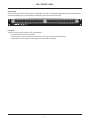
MS-1 FRONT PANEL
Setup and Use
The Vocia software provides an intuitive interface for configuration of the MS-1. The information supplied by this manual relates to physical
connections and assignment. For more details on software setup, please consult the Vocia Help File.
Message Server
Power
Network
Front Panel
The MS-1 features one power indication LED on the front panel:
1. Not illuminated: The device is not powered.
2. Flashing green: The unit is receiving power but not data, or the unit has not been configured correctly.
3. Solid green: The unit is operational. Power supply and network traffic are functional.
4
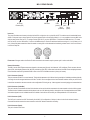
MS-1 REAR PANEL
MSB
LSB
Device ID
LAN1: Control
LAN2: CobranetTM
LAN3: VoIP
LAN4: Spare
O
Model MS-1
BIAMP SYSTEMS
RS232 Port
AC Power
Entrance (IEC)
USB Ports
LAN-1
LAN-3
Device ID
(control)
(VoIP)
LAN-2
LAN-4
(CobraNet) (Spare)
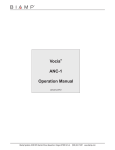
Device ID
The rotary ID switches are located on the back of the MS-1 and give the unit a unique Device ID. The switches are in hexadecimal format.
All MS-1 units must have a unique Device ID to function properly within a Vocia Paging World (i.e., it is not possible to have two MS-1 units
with the same Device ID of hex 07). To assign a Device ID of hex 07, turn the LSB switch to 7 and leave the MSB switch on 0. To create
an ID of hex B7, turn the LSB switch to 7 and turn the MSB switch to B. Device ID switches should be set using a 0.1 inch (2.5mm) to 0.12
inch (3.0mm) flat blade screwdriver. More information on setting IDs and the hexadecimal numbering scheme used in Vocia can be found
in the Vocia Help File.
Please note: Changes made to the Device ID while connected to the network require a power cycle in order to take effect.
Network Connection
The MS-1 has four RJ45 Ethernet connectors located on the rear panel (Control, Vocia Network, VoIP, and Spare). Each connector has two
green LEDs, which display Ethernet Link (left LED) and Activity (right LED). Unlike other Vocia devices, the MS-1 does not display the status
of the CobraNet conductor. By default the MS-1 takes on the role of CobraNet conductor (time synch master).
LAN-1 Connector (Control)
This port connects the MS-1 to a control network. This should be separate to the LAN that is being used by the CobraNet port either physically
or through the use of managed switches and VLANs. The MS-1 can be configured in the Vocia software interface via this port, and as such
it should be connected to the same network as the configuration PC during set up. It also supports inter-world paging and communications.
LAN-2 Connector (CobraNet)
This port is used to communicate with local Vocia devices and as such should be connected to the same network as the local Vocia system.
The data from the CobraNet network should be placed on its own LAN, either physically or through the use of managed switches and VLANs.
Vocia makes dynamic use of available bundles in CobraNet. Vocia devices are currently not interoperable with non-Vocia devices.
LAN-3 Connector (VoIP)
The VoIP port is used to host VoIP functionality for the MS-1. All configuration of this port is done via the Vocia software interface.
Connection should be made to the same network as other VoIP infrastructure within the facility.
LAN-4 Connector (Spare)
This port is inactive at this time.
5
MS-1 REAR PANEL
AC Power Entrance (IEC)
The IEC power entrance provides for connection of the appropriate power cord (included with unit). An internal universal switching power
supply accepts 100~240VAC @ 50/60Hz, with a maximum power consumption of 350 watts.
CAUTION: Do not remove or defeat the ground prong on the power cord, as this will constitute a shock hazard. Equipment should be connected
to a mains socket outlet with a protective earthing connection. This plug is the main disconnecting device and should remain readily operable.
There are no user interchangeable parts. Please contact Biamp Technical Support or your local distributor for all service requirements.
USB Ports
These ports are inactive at this time.
RS-232 Port
This port is used to support console access to the MS-1. Settings for connection are as follows: Baud rate 57600, Data bits 8, Parity None,
Stop bits 1, and Flow Control Hardware.
6
MS-1 INSTALLATION
Installation
The MS-1 requires one 1.75 inch (44.45 mm) high and 19 inch wide rack space with 17 inch (432 mm) depth. Mounting the unit using
four screws with washers will prevent marring of the front panel. PVC or nylon washers are appropriate. The unit should also be supported
at the rear to prevent bending of the enclosure and/or rack ears.
Please install the unit away from heat sources, such as vents and radiators, and in rooms with adequate ventilation. Ensure that air can
circulate freely behind, beside, and above the unit. Do not exceed the maximum ambient operating temperature of 32-113 degrees F
(45°C). Be aware of conditions in an enclosed rack that may cause the temperature to exceed ambient room conditions.
Add-On Features
The following features can be supported by the MS-1. Please consult the Vocia Help File for appropriate configuration.
Plug-and-Play Replacement
The MS-1 acts as a central configuration repository for all locally stored device configuration files. In case another Vocia device fails,
a replacement can be connected using the same Device ID settings. The new device will retrieve the appropriate configuration from
the MS-1 and set up automatically. Connection of an external PC is not required.
Comprehensive Logging and Monitoring
The MS-1 records and logs all system activities. The system log can be viewed via the Vocia software and exported using XML.
Recorded Message Storage and Playback
The MS-1 stores recorded messages for playback.
Scheduling of Recorded Messages and Events
The message scheduler provides the option of scheduling recurring recorded messages and events.
Inter-World Paging
Paging between two Vocia worlds is available if each world has an MS-1 in the system.
VoIP Paging
The MS-1 enables Voice over Internet Protocol (VoIP) access to allow paging from an attached VoIP PBX telephone system.
Third-Party Control
This interface enables third-party control systems to access the Vocia system remotely. More information on AMX, Crestron, and FIDS
support may be found in the Vocia Help File.
7
MS-1 SPECIFICATIONS
Message Server 1 SPECIFICATIONS
Connection:
Weight:
RJ45 with shielded Ethernet/PoE
cable (CAT5, CAT5e, CAT6 or CAT7)
Power Consumption
(100~240VAC 50/60Hz):
Dimensions:
Height:
Width:
Depth:
12 lbs. (5.4 kg)
Ambient Operating
Temperature Range:
< 350 watts
32-113 degrees F (0-45 degrees C)
Compliance:
RoHS directive
UL listed, CE marked
0.75 inches (44.5mm)
19 inches (483mm)
17.5 inches (444 mm)
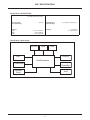
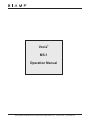
Message Server 1 Block Diagram
RS-232
USB
LED
VGA
Control
HostProcessor
ID Switches
Vocia
CobraNet
Storage
Drive
VoIP
8
MS-1 WARRANTY
BIAMP SYSTEMS IS PLEASED TO EXTEND THE FOLLOWING 5-YEAR LIMITED WARRANTY TO THE ORIGINAL PURCHASER OF
THE PROFESSIONAL SOUND EQUIPMENT DESCRIBED IN THIS MANUAL
1. BIAMP Systems warrants to the original purchaser of new products that the product will be free from defects in material and
workmanship for a period of 5 YEARS from the date of purchase from an authorized BIAMP Systems dealer, subject to the
terms and conditions set forth below.
2 If you notify BIAMP during the warranty period that a BIAMP Systems product fails to comply with the warranty, BIAMP Systems
will repair or replace, at BIAMP Systems’ option, the nonconforming product. As a condition to receiving the benefits of this warranty,
you must provide BIAMP Systems with documentation that establishes that you were the original purchaser of the products. Such
evidence may consist of your sales receipt from an authorized BIAMP Systems dealer. Transportation and insurance charges to
and from the BIAMP Systems factory for warranty service shall be your responsibility.
3. This warranty will be VOID if the serial number has been removed or defaced; or if the product has been altered, subjected to
damage, abuse or rental usage, repaired by any person not authorized by BIAMP Systems to make repairs; or installed in any
manner that does not comply with BIAMP Systems’ recommendations.
4. Electro-mechanical fans, electrolytic capacitors, gooseneck microphones, cords connecting handheld microphones, hard-drives,
displays, and normal wear and tear of items such as paint, knobs, handles, keypads and covers are not covered under this
warranty. All server-based devices are warranted for 3 years only.
5. This warranty is in lieu of all other warranties, expressed or implied. BIAMP Systems disclaims all other warranties, expressed
or implied, including, but not limited to, implied warranties of merchantability and fitness for a particular purpose.
6. The remedies set forth herein shall be the purchaser’s sole and exclusive remedies with respect to any defective product.
7. No agent, employee, distributor or dealer of BIAMP Systems is authorized to modify this warranty or to make additional warranties
on behalf of BIAMP Systems. Statements, representations or warranties made by any dealer do not constitute warranties
by BIAMP Systems. BIAMP Systems shall not be responsible or liable for any statement, representation or warranty made by any
dealer or other person.
8. No action for breach of this warranty may be commenced more than one year after the expiration of this warranty.
9. BIAMP systems shall not be liable for special, indirect, incidental, or consequential damages, including lost profits or loss of use
arising out of the purchase, sale, or use of the products, even if BIAMP Systems was advised of the possibility of such damages.
012011_585.0265.90A
9
COMPLIANCE
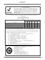
EU RoHS COMPLIANT
This Biamp product, including all attendant cables and
accessories supplied by Biamp, meets all requirements of EU
Directives 2002/95/EC of January 27, 2003, and 2005/618/EC
of August 18, 2005, the EU RoHS Directives. An EU RoHS
Materials Content Declaration document may be obtained at
www.biamp.com
(This information is presented to comply with the requirements of Chinese law SJ/T11363-2006)”
bG~£
Biamp Systems Corporation
¿Á^c+: (Audio File Server)
MS-1
¬5
¡Ae (Equipment Chassis) z (Power Cord)
F (Installation Hardware)
V$8"¾^k (Manual and Paper Documents)
,8Ub,g_ (Box and Packing Materials)
Pb
±
X
O
O
O
O
Hg
s
O
O
O
O
O
£T
Cd
Cr+6
PBB
·
!´
X
O
O
O
O
O
O
O
O
O
O
O
O
O
O
PBDE
O
O
O
O
O
0¢¬Ub=£g_
¨bobG~£ SJ/T11363-2006 º)r.
X¢¬
Ib=£g_U6¨bobG~£Â SJ/T11363-2006 º)r.
< D8T¶·U6=£g_
·1"-4~63¤§ 0.01%lY 91/338/EECj[lY
76/769/EECº)µ98i.¼~£8)*¬(
Um«»B
<TC~£U6=£g_
±1"-4~63¤§ 0.1%:
1) E:
#U6±
2) ±<°g
a4®63¦ 0.35%
3) ±<³g
a4®63¦ 0.4%
4) ±<²g
a4®63¦ 4%
5) Â}{|_
±/±_4®±6¤§ 85%
6) E½¬#±
7)
S|_
U6±ª]¯8Q@:,"
±6¤§ 80% 85%
8) ÀN¯ª]#±
9) H¥¸PSª
|_
<nLR%
;dº 10 Mha
• ?xO 0-40C (32-104°F)
• yO 0-95%`'
• vXÂO 0-10,000 J
• pu2¹
• tbqT"w© ¬
• z 110/220-Vac, 50/60 Hz, 6/3 A
• ¬tbZ>Z>¬N/
•
K0\f7W&g_©Ub
10