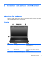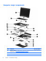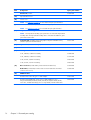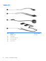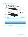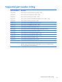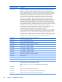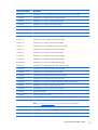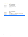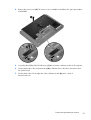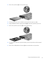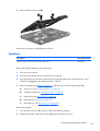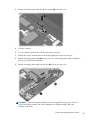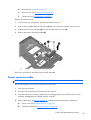
1
HP 6360t Mobile Thin Client
Maintenance and Service Guide
© Copyright 2011 Hewlett-Packard
Development Company, L.P.
Intel and Celeron are trademarks or
registered trademarks of Intel Corporation in
the United States and other countries.
Microsoft and Windows are either
trademarks or registered trademarks of
Microsoft Corporation in the United States
and/or other countries. SD Logo is a
trademark of its proprietor.
The information contained herein is subject
to change without notice. The only
warranties for HP products and services are
set forth in the express warranty statements
accompanying such products and services.
Nothing herein should be construed as
constituting an additional warranty. HP shall
not be liable for technical or editorial errors
or omissions contained herein.
First Edition: May 2011
Document Part Number: 652449-001
Safety warning notice
WARNING! To reduce the possibility of heat-related injuries or of overheating the computer, do not
place the computer directly on your lap or obstruct the computer air vents. Use the computer only on a
hard, flat surface. Do not allow another hard surface, such as an adjoining optional printer, or a soft
surface, such as pillows or rugs or clothing, to block airflow. Also, do not allow the AC adapter to
contact the skin or a soft surface, such as pillows or rugs or clothing, during operation. The computer
and the AC adapter comply with the user-accessible surface temperature limits defined by the
International Standard for Safety of Information Technology Equipment (IEC 60950).
iii
iv
Safety warning notice
Table of contents
1 Product description ........................................................................................................... 1
2 External component identification ..................................................................................... 5
Identifying the hardware ........................................................................................................... 5
Display ................................................................................................................................... 5
Buttons .................................................................................................................................... 6
TouchPad ................................................................................................................................ 7
Front ....................................................................................................................................... 8
Left side .................................................................................................................................. 9
Rear ....................................................................................................................................... 9
Right side .............................................................................................................................. 10
Bottom .................................................................................................................................. 11
3 Illustrated parts catalog .................................................................................................. 12
Service tag ............................................................................................................................ 13
Computer major components ................................................................................................... 14
Cable Kit .............................................................................................................................. 18
Display assembly subcomponents ............................................................................................. 19
Mass storage devices ............................................................................................................. 20
Miscellaneous parts ................................................................................................................ 21
Plastics Kit ............................................................................................................................. 22
Sequential part number listing .................................................................................................. 23
4 Removal and replacement procedures ............................................................................ 27
Preliminary replacement requirements ....................................................................................... 27
Tools required ......................................................................................................... 27
Service considerations ............................................................................................. 27
Plastic parts ............................................................................................. 27
Cables and connectors ............................................................................. 27
Drive handling ......................................................................................... 28
Grounding guidelines .............................................................................................. 28
v
Electrostatic discharge damage .................................................................. 28
Packaging and transporting guidelines ........................................ 29
Component replacement procedures ........................................................................................ 31
Service tag ............................................................................................................. 31
Computer feet ......................................................................................................... 32
Battery ................................................................................................................... 33
Solid-state module ................................................................................................... 34
Primary memory module .......................................................................................... 37
Optical drive .......................................................................................................... 38
Fan ....................................................................................................................... 40
Heat sink ................................................................................................................ 41
Processor ............................................................................................................... 43
WLAN module ........................................................................................................ 45
Keyboard ............................................................................................................... 47
RTC battery ............................................................................................................ 50
Expansion memory module ....................................................................................... 51
Base enclosure ........................................................................................................ 52
Speakers ................................................................................................................ 55
ExpressCard assembly ............................................................................................. 56
Display assembly .................................................................................................... 58
System board ......................................................................................................... 65
Power button board ................................................................................................. 67
Function board ....................................................................................................... 68
Power connector cable ............................................................................................ 69
5 Computer Setup .............................................................................................................. 71
Starting Computer Setup ......................................................................................................... 71
Using Computer Setup ............................................................................................................ 71
Navigating and selecting in Computer Setup .............................................................. 71
Restoring factory settings in Computer Setup ............................................................... 72
Computer Setup menus ........................................................................................................... 73
File menu ............................................................................................................... 73
Security menu ......................................................................................................... 73
System Configuration menu ...................................................................................... 74
6 Specifications ................................................................................................................. 76
Computer specifications .......................................................................................................... 76
13.3-in display specifications .................................................................................................. 77
vi
7 Power cord set requirements .......................................................................................... 78
Requirements for all countries .................................................................................................. 78
Requirements for specific countries and regions ......................................................................... 79
8 Recycling ........................................................................................................................ 80
Battery .................................................................................................................................. 80
Display ................................................................................................................................. 80
Index ................................................................................................................................. 86
vii
viii
1
Product description
Category
Description
Product Name
HP 6360t Mobile Thin Client
Processors
Intel® Celeron® B810 1.60-GHz processor (2.0-MB L3 cache, 2 threads, 35 W)
Chipset
Mobile Intel HM65 chipset
Graphics
Intel high-definition (HD) unified memory architecture (UMA) graphics
Supports dual-display ports through the dock
Panel
13.3-in, HD, AntiGlare, light-emitting diode (LED), SVA (1366×768) display;
16:9 aspect ratio
All display assemblies include 2 wireless local area network (WLAN) antenna cables
Supports privacy filter and low-voltage differential signalling
Memory
2 customer-accessible/upgradable memory module slots
Supports dual-channel memory
Supports up to 16,384 GB of system RAM
DDR3/1333-MHz
Supports the following configurations:
Solid-state module
●
16384-MB total system memory (8192×2, select models only)
●
8192-MB total system memory (4096×2 + 8192×1, select models only)
●
4096-MB total system memory (2048×2 or 4096×1)
●
2048-MB total system memory (2048×1)
2.0-GB solid-state module using a 2.5-in bracket
Customer-accessible
Serial ATA
Optical drive
Fixed
Serial ATA
12.7-mm tray load
DVD-ROM drive
1
Category
Description
Supports “no optical drive” option
Audio and video
HD audio
Integrated mono microphone on computer models equipped with a webcam
720p HD webcam (select models only)
Stereo speakers (2)
Modem
56K v.92 MDC data/fax modem
Support for "no modem" option
Ethernet
Intel 82579V 10/100/1000 Ethernet Gigabit Network Connection
NIC Power-down technology
S3/S4/S5 wake on LAN
Wireless
Integrated wireless local area network (WLAN) options by way of wireless module
Two WLAN antennas built into display assembly
Support for the following WLAN formats:
External media card
●
Broadcom 4313 802.11b/g/n 1×1 WiFi Adapter
●
Broadcom 43224AGN 802.11a/b/g/n 2×2 WiFi Adapter
54-mm ExpressCard
Integrated SD flash media slot supporting MultiMediaCard and Secure Digital
(SD) Memory Card
Ports
Docking
2
Chapter 1 Product description
●
3-pin AC power
●
Accessory battery connector
●
Audio-in (mono microphone)
●
Audio-out (stereo headphone)
●
DisplayPort v.1.1
●
Docking connector
●
eSATA/USB 2.0 Combo port
●
RJ-11 (modem)
●
RJ-45 (Ethernet, includes link and activity lights)
●
USB 2.0 (3 ports)
●
VGA (Dsub 15 pin) supporting: 1920×1200 external resolution @ 75 Hz hot
plug and unplug and auto-detection for correct output to wide-aspect vs.
standard aspect video
Support for the HP APR Docking Station and the HP PR Docking Station
Category
Description
Keyboard/pointing devices
Keyboard requirements:
●
Spill-resistant with drain
●
Full chiclet-style keyboard
Fn key functionality:
●
F3 – Sleep
●
F4 – Display Switching
●
F6 – Volume Down
●
F7 – Volume Up
●
F8 – MS Native Power Control
●
F9 – Brightness Down
●
F10 – Brightness Up
Touchpad requirements:
Power requirements
●
Touchpad only
●
On/off button
●
Supports 2-way scroll with legend
●
Taps enabled as default
●
Gestures disabled by default
Support for 9-cell 100-WHr LI-ion battery (3.00-AHr)
Support for 6-cell 62-WHr LI-ion battery (2.80-AHr)
Support for 6-cell 55-WHr LI-ion battery (2.55-AHr)
Support for 9-cell Lithium Polymer Extended Life Battery
Support for 9-cell Ultra Extended Life Battery
Support for HP Fast Charge Technology
65W HP Smart AC adapter with localized cable plug support (3-wire plug with
ground pin, supports 3-pin DC connector)
Security
Support Security Lock
Optional Integrated Smart Card Reader (Active)
Operating system
Preinstalled:
●
Windows® Embedded Standard 2009
●
Windows Embedded Standard 7
3
Category
Description
Web-only support:
Serviceability
4
Chapter 1 Product description
●
Windows Embedded Standard 2009
●
Windows Embedded Standard 7
End-user replaceable parts:
●
AC adapter
●
Battery
●
Solid-state module
●
Memory modules (2)
●
Optical drive
●
WLAN module
2
External component identification
Identifying the hardware
Components included with the computer may vary by region and model. The illustrations in this chapter
identify the standard features on most computer models.
Display
Item
Component
Description
(1)
Internal display switch
Turns off the display or initiates Sleep if the display is
closed while the power is on.
NOTE: The display switch is not visible from the outside
of the computer.
(2)
WLAN antennas (2)*
Send and receive wireless signals to communicate
with WLANs.
(3)
Webcam light (select models only)
On: The webcam is in use.
Identifying the hardware
5
Item
Component
Description
(4)
Internal microphone(s) (1 without webcam/
2 with webcam)
Records sound.
(5)
Webcam (select models only)
Records video and captures still photographs.
*The antennas are not visible from the outside of the computer. For optimal transmission, keep the areas immediately around
the antennas free from obstructions. To see wireless regulatory notices, refer to the section of the Regulatory, Safety, and
Environmental Notices that applies to your country or region. These notices are located in the Getting Started guide.
Buttons
Item
Component
Description
(1)
TouchPad on/off button
Turns the TouchPad on and off.
(2)
Power button
●
When the computer is off, press the button to turn on
the computer.
●
When the computer is on, press the button briefly to
initiate Sleep.
●
When the computer is in the Sleep state, press
the button briefly to exit Sleep.
If the computer has stopped responding and operating
system shutdown procedures are ineffective, press and
hold the power button for at least 5 seconds to turn off
the computer.
(3)
Wireless button
Turns the wireless feature on or off but does not establish
a wireless connection.
NOTE: A wireless connection may be established if
one has been previously configured.
6
Chapter 2 External component identification
Item
Component
Description
(4)
QuickWeb button (select models only)
●
When the computer is on, press the button to open
Internet Explorer.
●
When the computer is off or in the Sleep state
the button does not perform any action or function.
(5)
Volume mute button
Mutes and restores speaker sound.
Item
Component
Description
(1)
TouchPad on/off button
Turns the TouchPad on and off.
(2)
TouchPad zone
Moves the pointer and selects or activates items on
the screen.
(3)
Left TouchPad button
Functions like the left button on an external mouse.
(4)
Right TouchPad button
Functions like the right button on an external mouse.
TouchPad
NOTE: This table describes factory settings. To view or change pointing device preferences, select Start >
Control Panel > Mouse.
TouchPad
7
Front
Item
Component
Description
(1)
Display release latch
Opens the computer.
(2)
Wireless light
●
White: An integrated wireless device, such as a
WLAN device is on.
●
Amber: All wireless devices are off.
●
On: The computer is on.
●
Blinking: The computer is in the Sleep state.
●
Off: The computer is off.
●
Amber: The computer is connected to external
power and the battery is charged
from 0 to 90 percent.
●
White: The computer is connected to external power
and the battery is charged from 90 to 99 percent.
●
Blinking amber: A battery that is the only available
power source has reached a low battery level.
When the battery reaches a critical battery level,
the battery light begins blinking rapidly.
●
Off: The battery is fully charged.
●
Blinking white: The flash drive or optional optical
drive is being accessed.
●
Amber: HP 3D DriveGuard has been activated.
(3)
(4)
(5)
8
Power light
Battery light
Drive light
(6)
Speakers (2)
Produce sound.
(7)
Media Card Reader
Supports the following digital card formats:
Chapter 2 External component identification
●
MultiMediaCard
●
Secure Digital (SD) Memory Card
Left side
Item
Component
Description
(1)
Security cable slot
Attaches an optional security cable to the computer.
NOTE: The security cable is designed to act as a
deterrent, but it may not prevent the computer from being
mishandled or stolen.
(2)
RJ-45 (network) jack
Connects a network cable.
(3)
USB 2.0 port (2)
Connect optional USB devices.
(4)
ExpressCard slot or smart card reader
(depending on the configuration)
Supports optional ExpressCards or smart cards.
(5)
Optical drive (select models only)
Reads and writes (select models only) to an optical disc.
(6)
Optical drive eject button
(select models only)
Releases the optical drive disc tray.
Rear
Component
Description
Vent
Enables airflow to cool internal components.
NOTE: The computer fan starts up automatically to cool
internal components and prevent overheating. It is normal
for the internal fan to cycle on and off during
routine operation.
Left side
9
Right side
Item
Component
Description
(1)
Audio-out (headphone) jack
Produces sound when connected to optional powered
stereo speakers, headphones, earbuds, a headset, or
television audio.
WARNING! To reduce the risk of personal injury,
adjust the volume before putting on headphones,
earbuds, or a headset. For additional safety information,
refer to the Getting Started guide.
NOTE: When a device is connected to the jack,
the computer speakers are disabled.
10
(2)
Audio-in (microphone) jack
Connects an optional computer headset microphone,
stereo array microphone, or monaural microphone.
(3)
eSATA/USB 2.0 combo port
Connects a high-performance eSATA component, such as
an eSATA external hard drive, or connects an optional
USB device.
(4)
USB 2.0 port
Connect an optional USB device.
(5)
DisplayPort
Connects an optional digital display device, such as a
high-performance monitor or projector.
(6)
External monitor port
Connects an external VGA monitor or projector.
(7)
RJ-11 (modem) jack
Connects a modem cable.
(8)
Power connector
Connects an AC adapter.
Chapter 2 External component identification
Bottom
Item
Component
Description
(1)
Vents (2)
Enable airflow to cool internal components.
NOTE: The computer fan starts up automatically to cool
internal components and prevent overheating. It is normal
for the internal fan to cycle on and off during
routine operation.
(2)
Battery release latch
Releases the battery from the battery bay.
(3)
Docking connector
Connects an optional docking device.
(4)
Service cover release latch
Releases the service cover from the computer.
(5)
Battery bay
Holds the battery.
(6)
Accessory battery connector
Connects an optional accessory battery.
(7)
Wireless and memory module
compartments and flash drive bay
Holds the flash drive, and also contains the WLAN
module slot, and the memory module slots.
CAUTION: To prevent an unresponsive system, replace
the wireless module only with a wireless module
authorized for use in the computer by the governmental
agency that regulates wireless devices in your country or
region. If you replace the module and then receive a
warning message, remove the module to restore
computer functionality, and then contact
technical support.
Bottom
11
3
12
Illustrated parts catalog
Chapter 3 Illustrated parts catalog
Service tag
When ordering parts or requesting information, provide the computer serial number and model
description provided on the service tag.
Item
Description
Function
(1)
Product name
This is the product name affixed to the front of
the computer.
(2)
Serial number (s/n)
This is an alphanumeric identifier that is unique to
each product.
(3)
Part number/Product number (p/n)
This number provides specific information about the
product's hardware components. The part number
helps a service technician to determine what
components and parts are needed.
(4)
Warranty period
This number describes the duration of the warranty
period for the computer.
(5)
Model description
This is the alphanumeric identifier used to locate
documents, drivers, and support for the computer.
Service tag
13
Computer major components
Item
Component
(1)
Display assembly: The display assembly is spared at the subcomponent level only. For display assembly spare
part information, see Display assembly subcomponents on page 19.
(2)
Keyboard (includes keyboard cable):
For use in Belgium
14
Chapter 3 Illustrated parts catalog
Spare part number
639477-A41
Item
Component
Spare part number
For use in Bulgaria
639477-261
For use in the Denmark
639477-081
For use in Denmark, Finland, and Norway
639477-DH1
For use in the Netherlands
639477-B31
For use in Europe
639477-DW1
For use in French Canada
639477-121
For use in France
639477-051
For use in Germany
639477-041
For use in Greece
639477-DJ1
For use in Hungary
639477-211
For use in Iceland
639477-DD1
For use in Israel
639477-BB1
For use in Italy
639477-061
For use in Norway
639477-091
For use in Portugal
639477-131
For use in Russia
639477-251
For use in Saudi Arabia
639477-171
For use in Slovenia
639477-A81
For use in Spain
639477-071
For use in Sweden and Finland
639477-B71
For use in Switzerland
639477-BG1
For use in Turkey
639477-141
For use in the United Kingdom
639477-031
For use in the United States
639477-001
(3)
RTC battery
651038-001
(4)
Expansion memory module (PC3, 10600, 1333-MHz):
8 GB
634091-001
4 GB
621569-001
2 GB
581096-001
(5)
Top cover (includes TouchPad button and bracket)
658547-001
(6)
Power button board (includes cable)
639481-001
(7)
Function board (includes cable)
639480-001
Computer major components
15
Item
Component
Spare part number
Plastics Kit, includes:
639482-001
(8a)
ExpressCard slot bezel
(8b)
Service cover
NOTE:
(9)
Power connector cable (included in the Cable Kit, spare part number 639473-001)
NOTE:
(10)
See Plastics Kit on page 22 for more Plastics Kit spare part information.
See Cable Kit on page 18 for more Cable Kit spare part information.
ExpressCard assembly
639479-001
NOTE: The ExpressCard assembly spare part kit does not include the ExpressCard
assembly cable. The ExpressCard assembly cable is included in the Cable Kit, spare
part number 639473-001.
(11)
System board with HM65 chipset and graphics subsystem with UMA memory
(includes replacement thermal material)
655561-001
(12)
Speaker Kit (includes left and right speakers and cable)
639484-001
(13)
DVD-ROM drive (includes bezel and bracket)
647672-001
(14)
Battery:
(15)
(16)
16
9-cell, 100-Whr, 3.00-Ah Li-ion battery
634087-001
9-cell, 100-Whr, 3.00-Ah Li-ion battery
631243-001
6-cell, 62-Whr, 2.80-Ah Li-ion battery
628668-001
6-cell, 55-Whr, 2.55-Ah Li-ion battery
628666-001
Base enclosure (includes battery release latch and 4 rubber feet)
639468-001
Rubber Kit (not illustrated, includes 7 base enclosure rubber feet and 4 base
enclosure screw covers)
639483-001
WLAN module:
Broadcom 4313 802.11b/g/n 1×1 WiFi Adapter
593836-001
Broadcom 43224AGN 802.11a/b/g/n 2×2 WiFi Adapter for use in
Antigua and Barbuda, Barbados, Belize, Canada, the Cayman Islands, Guam,
Puerto Rico, Trinidad and Tobago, the U.S. Virgin Islands, and the United States
582564-001
Chapter 3 Illustrated parts catalog
Item
(17)
Component
Spare part number
Broadcom 43224AGN 802.11a/b/g/n 2×2 WiFi Adapter for use in Afghanistan,
Albania, Algeria, Andorra, Angola, Antigua and Barbuda, Argentina, Armenia,
Aruba, Australia, Austria, Azerbaijan, the Bahamas, Bahrain, Bangladesh, Barbados,
Belarus, Belgium, Belize, Benin, Bermuda, Bhutan, Bolivia, Bosnia and Herzegovina,
Botswana, Brazil, the British Virgin Islands, Brunei, Bulgaria, Burkina Faso, Burundi,
Cameroon, Cape Verde, the Central African Republic, Chad, Chile,
the People's Republic of China, Colombia, Comoros, the Congo, Costa Rica, Croatia,
Cyprus, the Czech Republic, Denmark, Djibouti, Dominica, the Dominican Republic,
East Timor, Ecuador, Egypt, El Salvador, Equitorial Guinea, Eritrea, Estonia, Ethiopia,
Fiji, Finland, France, French Guiana, Gabon, Gambia, Georgia, Germany, Ghana,
Gibraltar, Greece, Grenada, Guadeloupe, Guatemala, Guinea, Guinea-Bissau,
Guyana, Haiti, Honduras, Hong Kong, Hungary, Iceland, India, Ireland, Israel, Italy,
the Ivory Coast, Jamaica, Jordan, Kazakhstan, Kenya, Kiribati, Kyrgyzstan, Laos,
Latvia, Lebanon, Lesotho, Liberia, Liechtenstein, Lithuania, Luxembourg, Macedonia,
Madagascar, Malawi, Malaysia, the Maldives, Mali, Malta, the Marshall Islands,
Martinique, Mauritania, Mauritius, Mexico, Micronesia, Monaco, Mongolia,
Montenegro, Morocco, Mozambique, Namibia, Nauru, Nepal, the Nether Antilles,
the Netherlands, New Zealand, Nicaragua, Niger, Nigeria, Norway, Oman,
Pakistan, Palau, Panama, Papua New Guinea, Paraguay, Peru, the Philippines,
Poland, Portugal, the Republic of Moldova, Romania, Russia, Rwanda, Samoa,
San Marino, Sao Tome and Principe, Saudi Arabia, Senegal, Serbia, the Seychelles,
Sierra Leone, Singapore, Slovakia, Slovenia, the Solomon Islands, Somalia,
South Africa, South Korea, Spain, Sri Lanka, St. Kitts and Nevis, St. Lucia,
St. Vincent and the Grenadines, Suriname, Swaziland, Sweden, Switzerland, Taiwan,
Tajikistan, Tanzania, Togo, Tonga, Trinidad and Tobago, Tunisia, Turkey,
Turkmenistan, Tuvalu, Uganda, Ukraine, the United Arab Emirates,
the United Kingdom, Uruguay, Uzbekistan, Vanuatu, Venezuela, Vietnam, Yemen,
Zaire, Zambia, and Zimbabwe
582564-002
Primary memory module (PC3, 10600, 1333-MHz):
8 GB
634091-001
4 GB
621569-001
2 GB
581096-001
2.0 GB solid-state module (2.5-in, 7.0-mm, SATA; does not include solid-state
module bracket or screws)
656837-001
Solid-state Module Hardware Kit (not illustrated, includes solid-state module
bracket and screws)
651649-001
(19)
Intel Celeron B810 1.60-GHz processor (1-MB L2 cache, 800-MHz FSB,
includes replacement thermal material)
646760-001
(20)
Heat sink (includes replacement thermal material)
639475-001
(21)
Fan
639474-001
(18)
Computer major components
17
Cable Kit
Item
18
Component
Spare part number
Cable Kit, includes:
639473-001
(1)
TouchPad cable
(2)
ExpressCard assembly cable
(3)
Power connector cable
(4)
Wireless antenna
Chapter 3 Illustrated parts catalog
Display assembly subcomponents
Item
Component
(1)
Display hinge covers (2, included in the Plastics Kit, spare part number 639482-001)
NOTE:
Spare part number
See Plastics Kit on page 22 for more Plastics Kit spare part information.
(2)
Display bezel
655562-001
(3)
Microphone module
647675-001
(4)
Display Hinge Kit (includes left and right display hinges and brackets)
639476-001
(5)
13.3-in, HD, AG, LED, display panel
647671-001
(6)
WLAN antenna cables (included in the Cable Kit, spare part number 639473-001; includes
WLAN cables and transceivers)
NOTE:
See Cable Kit on page 18 for more Cable Kit spare part information.
(7)
Display Cable Kit (includes display panel cable and microphone module cable)
639472-001
(8)
Display enclosure
639467-001
Display assembly subcomponents
19
Mass storage devices
Item
Component
Spare part number
(1)
2.0-GB solid-state module (2.5-in, 7.0-mm, SATA; does not include solid-state
module bracket or screws)
656837-001
Solid-state Module Hardware Kit, includes:
651649-001
(2)
Solid-state module bracket
Screws (not illustrated)
(3)
20
DVD-ROM drive (includes bezel and bracket)
Chapter 3 Illustrated parts catalog
647672-001
Miscellaneous parts
Component
Spare part number
HP Smart AC adapter:
65-W RC V HP Smart AC adapter
609939-001
65-W RC V EM HP Smart AC adapter
609948-001
Power cord (3-pin, black, 1.83-m):
For use in Australia
490371-011
For use in Europe
490371-021
For use in India
490371-D61
For use in Israel
490371-BB1
For use in Italy
490371-061
For use in Japan
490371-291
For use in North America
490371-001
For use in the People's Republic of China
490371-AA1
For use in South Africa
490371-AR1
For use in South Korea
490371-AD1
For use in Switzerland
490371-111
For use in Taiwan
490371-AB1
For use in Thailand
490371-201
For use in the United Kingdom and Singapore
490371-031
Screw Kit
647676-001
Miscellaneous parts
21
Plastics Kit
Item
22
Component
Spare part number
Plastics Kit, includes:
639482-001
(1)
Display hinge covers (2)
(2)
ExpressCard slot space saver
(3)
Service cover
Chapter 3 Illustrated parts catalog
Sequential part number listing
Spare part number
Description
490371-001
Power cord for use in North America (3-pin, black, 1.83-m)
490371-011
Power cord for use in Australia (3-pin, black, 1.83-m)
490371-021
Power cord for use in Europe (3-pin, black, 1.83-m)
490371-031
Power cord for use in the United Kingdom and Singapore (3-pin, black, 1.83-m)
490371-061
Power cord for use in Italy (3-pin, black, 1.83-m)
490371-111
Power cord for use in Switzerland (3-pin, black, 1.83-m)
490371-201
Power cord for use in Thailand (3-pin, black, 1.83-m)
490371-291
Power cord for use in Japan (3-pin, black, 1.83-m)
490371-AA1
Power cord for use in the People's Republic of China (3-pin, black, 1.83-m)
490371-AB1
Power cord for use in Taiwan (3-pin, black, 1.83-m)
490371-AD1
Power cord for use in South Korea (3-pin, black, 1.83-m)
490371-AR1
Power cord for use in South Africa (3-pin, black, 1.83-m)
490371-BB1
Power cord for use Israel (3-pin, black, 1.83-m)
490371-D61
Power cord for use in India (3-pin, black, 1.83-m)
581096-001
2-MB memory module (PC3, 10600, 1333-MHz)
582564-001
Broadcom 43224AGN 802.11a/b/g/n 2×2 WiFi Adapter for use in Antigua and Barbuda,
Barbados, Belize, Canada, the Cayman Islands, Guam, Puerto Rico, Trinidad and Tobago,
the U.S. Virgin Islands, and the United States
Sequential part number listing
23
Spare part number
Description
582564-002
Broadcom 43224AGN 802.11a/b/g/n 2×2 WiFi Adapter for use in Afghanistan, Albania,
Algeria, Andorra, Angola, Antigua and Barbuda, Argentina, Armenia, Aruba, Australia, Austria,
Azerbaijan, the Bahamas, Bahrain, Bangladesh, Barbados, Belarus, Belgium, Belize, Benin,
Bermuda, Bhutan, Bolivia, Bosnia and Herzegovina, Botswana, Brazil, the British Virgin Islands,
Brunei, Bulgaria, Burkina Faso, Burundi, Cameroon, Cape Verde, the Central African Republic,
Chad, Chile, the People's Republic of China, Colombia, Comoros, the Congo, Costa Rica,
Croatia, Cyprus, the Czech Republic, Denmark, Djibouti, Dominica, the Dominican Republic,
East Timor, Ecuador, Egypt, El Salvador, Equitorial Guinea, Eritrea, Estonia, Ethiopia, Fiji,
Finland, France, French Guiana, Gabon, Gambia, Georgia, Germany, Ghana, Gibraltar,
Greece, Grenada, Guadeloupe, Guatemala, Guinea, Guinea-Bissau, Guyana, Haiti, Honduras,
Hong Kong, Hungary, Iceland, India, Ireland, Israel, Italy, the Ivory Coast, Jamaica, Jordan,
Kazakhstan, Kenya, Kiribati, Kyrgyzstan, Laos, Latvia, Lebanon, Lesotho, Liberia, Liechtenstein,
Lithuania, Luxembourg, Macedonia, Madagascar, Malawi, Malaysia, the Maldives, Mali, Malta,
the Marshall Islands, Martinique, Mauritania, Mauritius, Mexico, Micronesia, Monaco, Mongolia,
Montenegro, Morocco, Mozambique, Namibia, Nauru, Nepal, the Nether Antilles,
the Netherlands, New Zealand, Nicaragua, Niger, Nigeria, Norway, Oman, Pakistan, Palau,
Panama, Papua New Guinea, Paraguay, Peru, the Philippines, Poland, Portugal,
the Republic of Moldova, Romania, Russia, Rwanda, Samoa, San Marino,
Sao Tome and Principe, Saudi Arabia, Senegal, Serbia, the Seychelles, Sierra Leone, Singapore,
Slovakia, Slovenia, the Solomon Islands, Somalia, South Africa, South Korea, Spain, Sri Lanka,
St. Kitts and Nevis, St. Lucia, St. Vincent and the Grenadines, Suriname, Swaziland, Sweden,
Switzerland, Taiwan, Tajikistan, Tanzania, Togo, Tonga, Trinidad and Tobago, Tunisia, Turkey,
Turkmenistan, Tuvalu, Uganda, Ukraine, the United Arab Emirates, the United Kingdom, Uruguay,
Uzbekistan, Vanuatu, Venezuela, Vietnam, Yemen, Zaire, Zambia, and Zimbabwe
593836-001
Broadcom 4313 802.11b/g/n 1×1 WiFi Adapter
609939-001
65-W RC V HP Smart AC adapter
609948-001
65-W RC V EM HP Smart AC adapter
621569-001
4-MB memory module (PC3, 10600, 1333-MHz)
628666-001
6-cell, 55-Whr, 2.55-Ah Li-ion battery
628668-001
6-cell, 62-Whr, 2.80-Ah Li-ion battery
631243-001
9-cell, 100-Whr, 3.00-Ah Li-ion battery
634087-001
9-cell, 100-Whr, 3.00-Ah Li-ion battery
634091-001
8-MB memory module (PC3, 10600, 1333-MHz)
639467-001
Display enclosure
639468-001
Base enclosure (includes battery release latch and 4 rubber feet)
639472-001
Display Cable Kit (includes display panel cable and webcam/microphone module cable)
639473-001
Cable Kit (includes the ExpressCard assembly cable, power connector cable, TouchPad cable,
WLAN antenna cable, and WWAN antenna cable)
NOTE:
24
See Cable Kit on page 18 for more Cable Kit spare part information.
639474-001
Fan
639475-001
Heat sink (includes replacement thermal material)
639476-001
Display Hinge Kit (includes left and right display hinges and brackets)
639477-001
Keyboard for use in the United States (includes keyboard cable)
Chapter 3 Illustrated parts catalog
Spare part number
Description
639477-031
Keyboard for use in the United Kingdom and Singapore (includes keyboard cable)
639477-041
Keyboard for use in Germany (includes keyboard cable)
639477-051
Keyboard for use in France (includes keyboard cable)
639477-061
Keyboard for use in Italy (includes keyboard cable)
639477-071
Keyboard for use in Spain (includes keyboard cable)
639477-081
Keyboard for use in Denmark Norway (includes keyboard cable)
639477-091
Keyboard for use in Norway (includes keyboard cable)
639477-121
Keyboard for use in French Canada (includes keyboard cable)
639477-131
Keyboard for use in Portugal (includes keyboard cable)
639477-141
Keyboard for use in Turkey (includes keyboard cable)
639477-171
Keyboard for use in Saudi Arabia (includes keyboard cable)
639477-211
Keyboard for use in Hungary (includes keyboard cable)
639477-251
Keyboard for use in Russia (includes keyboard cable)
639477-261
Keyboard for use in Bulgaria (includes keyboard cable)
639477-A41
Keyboard for use in Belgium (includes keyboard cable)
639477-A81
Keyboard for use in Slovenia (includes keyboard cable)
639477-B31
Keyboard for use in the Netherlands (includes keyboard cable)
639477-B71
Keyboard for use in Slovenia (includes keyboard cable)
639477-BB1
Keyboard for use in Israel (includes keyboard cable)
639477-BG1
Keyboard for use in Switzerland (includes keyboard cable)
639477-DD1
Keyboard for use in Iceland (includes keyboard cable)
639477-DH1
Keyboard for use in Denmark, Finland, and Norway (includes keyboard cable)
639477-DJ1
Keyboard for use in Greece (includes keyboard cable)
639477-DW1
Keyboard for use in Europe (includes keyboard cable)
639479-001
ExpressCard assembly
639480-001
Function board (includes cable)
639481-001
Power button board (includes cable)
639482-001
Plastics Kit (includes 2 display hinge covers, ExpressCard slot space saver, and service cover)
NOTE:
See Plastics Kit on page 22 for more Plastics Kit spare part information.
639483-001
Rubber Kit (includes 7 base enclosure rubber feet and 4 base enclosure screw covers)
639484-001
Speaker Kit (includes left and right speakers and cable)
641735-001
Webcam/microphone module
Sequential part number listing
25
26
Spare part number
Description
646760-001
Intel Celeron B810 1.60-GHz processor (1-MB L2 cache, 800-MHz FSB)
(includes replacement thermal material)
647671-001
13.3-in, HD, AG, LED, display panel
647672-001
DVD-ROM drive (includes bezel and bracket)
647675-001
Microphone module
647676-001
Screw Kit
651038-001
RTC battery
651649-001
Solid-state Module Hardware Kit (includes solid-state module bracket and screws)
655561-001
System board with HM65 chipset and graphics subsystem with UMA memory
(includes replacement thermal material)
655562-001
Display bezel
656837-001
2.0-GB solid-state module (2.5-in, 7.0-mm, SATA; does not include solid-state module
bracket or screws)
658547-001
Top cover (includes TouchPad button and bracket)
Chapter 3 Illustrated parts catalog
4
Removal and replacement
procedures
Preliminary replacement requirements
Tools required
You will need the following tools to complete the removal and replacement procedures:
●
Flat-bladed screwdriver
●
Magnetic screwdriver
●
Phillips P0 and P1 screwdrivers
Service considerations
The following sections include some of the considerations that you must keep in mind during
disassembly and assembly procedures.
NOTE: As you remove each subassembly from the computer, place the subassembly (and all
accompanying screws) away from the work area to prevent damage.
Plastic parts
CAUTION: Using excessive force during disassembly and reassembly can damage plastic parts. Use
care when handling the plastic parts. Apply pressure only at the points designated in
the maintenance instructions.
Cables and connectors
CAUTION: When servicing the computer, be sure that cables are placed in their proper locations
during the reassembly process. Improper cable placement can damage the computer.
Cables must be handled with extreme care to avoid damage. Apply only the tension required to unseat
or seat the cables during removal and insertion. Handle cables by the connector whenever possible. In
all cases, avoid bending, twisting, or tearing cables. Be sure that cables are routed in such a way that
they cannot be caught or snagged by parts being removed or replaced. Handle flex cables with
extreme care; these cables tear easily.
Preliminary replacement requirements
27
Drive handling
CAUTION: Drives are fragile components that must be handled with care. To prevent damage to
the computer, damage to a drive, or loss of information, observe these precautions:
Before removing or inserting a hard drive, shut down the computer.
Before handling a drive, be sure that you are discharged of static electricity. While handling a drive,
avoid touching the connector.
Before removing a diskette drive or optical drive, be sure that a diskette or disc is not in the drive and
be sure that the optical drive tray is closed.
Handle drives on surfaces covered with at least one inch of shock-proof foam.
Avoid dropping drives from any height onto any surface.
After removing a hard drive, an optical drive, or a diskette drive, place it in a static-proof bag.
Avoid exposing an internal hard drive to products that have magnetic fields, such as monitors
or speakers.
Avoid exposing a drive to temperature extremes or liquids.
If a drive must be mailed, place the drive in a bubble pack mailer or other suitable form of protective
packaging and label the package “FRAGILE.”
Grounding guidelines
Electrostatic discharge damage
Electronic components are sensitive to electrostatic discharge (ESD). Circuitry design and structure
determine the degree of sensitivity. Networks built into many integrated circuits provide some
protection, but in many cases, ESD contains enough power to alter device parameters or melt
silicon junctions.
A discharge of static electricity from a finger or other conductor can destroy static-sensitive devices or
microcircuitry. Even if the spark is neither felt nor heard, damage may have occurred.
An electronic device exposed to ESD may not be affected at all and can work perfectly throughout
a normal cycle. Or the device may function normally for a while, then degrade in the internal layers,
reducing its life expectancy.
CAUTION: To prevent damage to the computer when you are removing or installing internal
components, observe these precautions:
Keep components in their electrostatic-safe containers until you are ready to install them.
Before touching an electronic component, discharge static electricity by using the guidelines described
in this section.
Avoid touching pins, leads, and circuitry. Handle electronic components as little as possible.
If you remove a component, place it in an electrostatic-safe container.
28
Chapter 4 Removal and replacement procedures
The following table shows how humidity affects the electrostatic voltage levels generated by
different activities.
CAUTION: A product can be degraded by as little as 700 V.
Typical electrostatic voltage levels
Relative humidity
Event
10%
40%
55%
Walking across carpet
35,000 V
15,000 V
7,500 V
Walking across vinyl floor
12,000 V
5,000 V
3,000 V
Motions of bench worker
6,000 V
800 V
400 V
Removing DIPS from plastic tube
2,000 V
700 V
400 V
Removing DIPS from vinyl tray
11,500 V
4,000 V
2,000 V
Removing DIPS from Styrofoam
14,500 V
5,000 V
3,500 V
Removing bubble pack from PCB
26,500 V
20,000 V
7,000 V
Packing PCBs in foam-lined box
21,000 V
11,000 V
5,000 V
Packaging and transporting guidelines
Follow these grounding guidelines when packaging and transporting equipment:
●
To avoid hand contact, transport products in static-safe tubes, bags, or boxes.
●
Protect ESD-sensitive parts and assemblies with conductive or approved containers or packaging.
●
Keep ESD-sensitive parts in their containers until the parts arrive at static-free workstations.
●
Place items on a grounded surface before removing items from their containers.
●
Always be properly grounded when touching a component or assembly.
●
Store reusable ESD-sensitive parts from assemblies in protective packaging or
nonconductive foam.
●
Use transporters and conveyors made of antistatic belts and roller bushings. Be sure that
mechanized equipment used for moving materials is wired to ground and that proper materials
are selected to avoid static charging. When grounding is not possible, use an ionizer to dissipate
electric charges.
Workstation guidelines
Follow these grounding workstation guidelines:
●
Cover the workstation with approved static-shielding material.
●
Use a wrist strap connected to a properly grounded work surface and use properly grounded tools
and equipment.
Preliminary replacement requirements
29
●
Use conductive field service tools, such as cutters, screwdrivers, and vacuums.
●
When fixtures must directly contact dissipative surfaces, use fixtures made only of staticsafe materials.
●
Keep the work area free of nonconductive materials, such as ordinary plastic assembly aids
and Styrofoam.
●
Handle ESD-sensitive components, parts, and assemblies by the case or PCM laminate. Handle
these items only at static-free workstations.
●
Avoid contact with pins, leads, or circuitry.
●
Turn off power and input signals before inserting or removing connectors or test equipment.
Equipment guidelines
Grounding equipment must include either a wrist strap or a foot strap at a grounded workstation.
●
When seated, wear a wrist strap connected to a grounded system. Wrist straps are flexible straps
with a minimum of one megohm ±10% resistance in the ground cords. To provide proper ground,
wear a strap snugly against the skin at all times. On grounded mats with banana-plug connectors,
use alligator clips to connect a wrist strap.
●
When standing, use foot straps and a grounded floor mat. Foot straps (heel, toe, or boot straps)
can be used at standing workstations and are compatible with most types of shoes or boots. On
conductive floors or dissipative floor mats, use foot straps on both feet with a minimum of one
megohm resistance between the operator and ground. To be effective, the conductive must be
worn in contact with the skin.
The following grounding equipment is recommended to prevent electrostatic damage:
●
Antistatic tape
●
Antistatic smocks, aprons, and sleeve protectors
●
Conductive bins and other assembly or soldering aids
●
Nonconductive foam
●
Conductive tabletop workstations with ground cords of one megohm resistance
●
Static-dissipative tables or floor mats with hard ties to the ground
●
Field service kits
●
Static awareness labels
●
Material-handling packages
●
Nonconductive plastic bags, tubes, or boxes
●
Metal tote boxes
●
Electrostatic voltage levels and protective materials
The following table lists the shielding protection provided by antistatic bags and floor mats.
30
Chapter 4 Removal and replacement procedures
Material
Use
Voltage protection level
Antistatic plastics
Bags
1,500 V
Carbon-loaded plastic
Floor mats
7,500 V
Metallized laminate
Floor mats
5,000 V
Component replacement procedures
This chapter provides removal and replacement procedures.
There are as many as 75 screws that must be removed, replaced, or loosened when servicing
the computer. Make special note of each screw size and location during removal and replacement.
Service tag
When ordering parts or requesting information, provide the computer serial number and model number
provided on the service tag.
Item
Description
Function
(1)
Product name
This is the product name affixed to the front of
the computer.
Component replacement procedures
31
Item
Description
Function
(2)
Serial number (s/n)
This is an alphanumeric identifier that is unique to
each product.
(3)
Part number/Product number (p/n)
This number provides specific information about
the product's hardware components. The part number
helps a service technician to determine what
components and parts are needed.
(4)
Warranty period
This number describes the duration of the warranty
period for the computer.
(5)
Model description
This is the alphanumeric identifier used to locate
documents, drivers, and support for the computer.
Computer feet
The computer feet are adhesive-backed rubber pads. There are 7 rubber feet, in two different sizes,
large (1) and small (2), that attach to the base enclosure in the locations illustrated below. The
computer feet are available in the Rubber Kit, spare part number 639483-001.
32
Chapter 4 Removal and replacement procedures
Battery
Description
Spare part number
9-cell, 100-Whr, 3.00-Ah Li-ion battery
634087-001
9-cell, 100-Whr, 3.00-Ah Li-ion battery
631243-001
6-cell, 62-Whr, 2.80-Ah Li-ion battery
628668-001
6-cell, 55-Whr, 2.55-Ah Li-ion battery
628666-001
Before disassembling the computer, follow these steps:
1.
Shut down the computer.
2.
Disconnect all external devices connected to the computer.
3.
Disconnect the power from the computer by first unplugging the power cord from the AC outlet
and then unplugging the AC adapter from the computer.
Remove the battery:
1.
Turn the computer upside down on a flat surface, with the battery bay toward you.
2.
Slide the battery release latch (1) to release the battery.
3.
Remove the battery (2) from the computer.
Install the battery by inserting it into the battery bay until you hear a click.
Component replacement procedures
33
Solid-state module
NOTE: The solid-state module spare part kit does not include the solid-state module bracket or screws.
The solid-state module bracket and screws are included in the Solid-state Module Hardware Kit, spare
part number 651649-001.
Description
Spare part number
2.0-GB solid-state module (2.5-in, 7.0-mm, SATA)
656837-001
Before removing the solid-state module, follow these steps:
1.
Shut down the computer.
2.
Disconnect all external devices connected to the computer.
3.
Disconnect the power from the computer by first unplugging the power cord from the AC outlet
and then unplugging the AC adapter from the computer.
4.
Remove the battery (see Battery on page 33).
Remove the solid-state module:
1.
Slide the service cover release latch (1) to the left.
2.
If the optional security screw (2) is being used, remove the screw, and then slide the release latch
again (3) to release the service cover.
NOTE: If you want to use the optional screw, it is stored inside the service cover.
3.
34
Slide the service cover forward (4) until it disengages from the computer.
Chapter 4 Removal and replacement procedures
4.
Remove the service cover (5). The service cover is available in the Plastics Kit, spare part number
639482-001.
5.
Loosen the three Phillips PM2.5×9.0 screws (1) that secure the solid-state module to the computer.
6.
Use the plastic tab on the solid-state module (2) to slide the drive to the left to disconnect it from
the system board.
7.
Use the plastic tab to lift the right side of the solid-state module (3) until it is clear of
the base enclosure.
Component replacement procedures
35
8.
Remove the solid-state module (4) by sliding it up and away from the computer at an angle.
9.
If it is necessary to replace the solid-state module screws (1) and bracket (2), remove and replace
the components.
Reverse this procedure to reassemble and install the solid-state module.
36
Chapter 4 Removal and replacement procedures
Primary memory module
Description
Spare part number
8 GB
634091-001
4 GB
621569-001
2 GB
581096-001
Before removing the primary memory module, follow these steps:
1.
Shut down the computer.
2.
Disconnect all external devices connected to the computer.
3.
Disconnect the power from the computer by first unplugging the power cord from the AC outlet
and then unplugging the AC adapter from the computer.
4.
Remove the battery (see Battery on page 33).
5.
Remove the service cover (see Solid-state module on page 34).
Remove the primary memory module:
1.
Pull away the retention clips (1) on each side of the memory module. (The memory
module tilts up.)
2.
Grasp the edge of the memory module, and then gently pull the memory module (2) out of
the memory module slot.
CAUTION: To prevent damage to the memory module, hold the memory module by the edges
only. Do not touch the components on the memory module.
To protect a memory module after removal, place it in an electrostatic-safe container.
Reverse this procedure to install the primary memory module.
Component replacement procedures
37
Optical drive
NOTE: The optical drive spare part kit includes a bezel and bracket.
Description
Spare part number
DVD-ROM drive
647672-001
Before removing the optical drive, follow these steps:
1.
Shut down the computer.
2.
Disconnect all external devices connected to the computer.
3.
Disconnect the power from the computer by first unplugging the power cord from the AC outlet
and then unplugging the AC adapter from the computer.
4.
Remove the battery (see Battery on page 33).
5.
Remove the service cover (see Solid-state module on page 34).
Remove the optical drive:
38
1.
Remove the four screws that secure the optical drive to the computer.
2.
Loosen the optical drive captive screw (1).
3.
Using a flat-bladed screwdriver, gently push the tab (2) to release the optical drive.
Chapter 4 Removal and replacement procedures
4.
Remove the optical drive (3) from the optical drive bay.
5.
If the optical drive space saver is installed, loosen the optical drive captive screw (1).
6.
Using a flat-bladed screwdriver, gently push the tab (2) to release the optical drive space saver.
7.
Remove the optical drive space saver (3) from the optical drive bay.
8.
If it is necessary to replace the optical drive bracket, position the optical drive with the rear panel
toward you.
9.
Remove the two Phillips PM2.0×3.0 screws (1) that secure the bracket to the optical drive.
Component replacement procedures
39
10. Remove the optical drive bracket (2).
Reverse this procedure to reassemble and install the optical drive.
Fan
Description
Spare part number
Fan
639474-001
NOTE: To properly ventilate the computer, allow at least 7.6 cm (3 in) of clearance on the left side of
the computer. The computer uses an electric fan for ventilation. The fan is controlled by a temperature
sensor and is designed to turn on automatically when high temperature conditions exist. These
conditions are affected by high external temperatures, system power consumption, power
management/battery conservation configurations, battery fast charging, and software requirements.
Exhaust air is displaced through the ventilation grill located on the left side of the computer.
Before removing the fan, follow these steps:
1.
Shut down the computer.
2.
Disconnect all external devices connected to the computer.
3.
Disconnect the power from the computer by first unplugging the power cord from the AC outlet
and then unplugging the AC adapter from the computer.
4.
Remove the battery (see Battery on page 33).
5.
Remove the service cover (see Solid-state module on page 34).
Remove the fan:
40
1.
Disconnect the fan cable (1) from the system board.
2.
Loosen the two Phillips PM2.5×7.0 captive screws (2) that secure the fan to the system board.
Chapter 4 Removal and replacement procedures
3.
Remove the fan (3).
Reverse this procedure to install the fan.
Heat sink
Description
Spare part number
Heat sink (includes replacement thermal material)
639475-001
Before removing the heat sink, follow these steps:
1.
Shut down the computer.
2.
Disconnect all external devices connected to the computer.
3.
Disconnect the power from the computer by first unplugging the power cord from the AC outlet
and then unplugging the AC adapter from the computer.
4.
Remove the battery (see Battery on page 33).
5.
Remove the service cover (see Solid-state module on page 34).
6.
Remove the fan (see Fan on page 40).
Component replacement procedures
41
Remove the heat sink:
1.
Loosen the four captive Phillips PM2.5×10.0 screws (1) that secure the heat sink to
the system board.
NOTE: Due to the adhesive quality of the thermal material located between the heat sink and
system board components, it may be necessary to move the heat sink from side to side
to detach it.
2.
Lift the left side (2) of the heat sink until it disengages from the system board.
3.
Rotate the heat sink (3) counterclockwise until it is clear of the rear right corner of
the base enclosure.
4.
Remove the heat sink.
The thermal material must be thoroughly cleaned from the surfaces of the heat sink and
the system board components each time the heat sink is removed. Replacement thermal material is
included with the heat sink, processor, and system board spare part kits. Thermal paste is used on
the processor (1) and the heat sink section (2) that services it.
42
Chapter 4 Removal and replacement procedures
Reverse this procedure to reassemble and install the heat sink.
Processor
Description
Spare part number
Intel Celeron B810 1.60-GHz processor (1-MB L2 cache, 800-MHz FSB,
includes replacement thermal material)
646760-001
Before removing the processor, follow these steps:
1.
Shut down the computer.
2.
Disconnect all external devices connected to the computer.
3.
Disconnect the power from the computer by first unplugging the power cord from the AC outlet
and then unplugging the AC adapter from the computer.
4.
Remove the battery (see Battery on page 33), and then remove the following components:
●
Service cover (see Solid-state module on page 34)
●
Fan (see Fan on page 40)
●
Heat sink (see Heat sink on page 41)
Remove the processor:
1.
Use a flat-bladed screw driver to turn the processor locking screw one-half turn
counterclockwise (1), until you hear a click.
Component replacement procedures
43
2.
Lift the processor (2) straight up, and then remove it.
NOTE: The gold triangle (3) on the processor must be aligned with the triangle icon (4)
embossed on the processor socket when you install the processor.
Reverse this procedure to install the processor.
44
Chapter 4 Removal and replacement procedures
WLAN module
Description
Spare part number
Broadcom 4313 802.11b/g/n 1×1 WiFi Adapter
593836-001
Broadcom 43224AGN 802.11a/b/g/n 2×2 WiFi Adapter for use in Antigua and Barbuda,
Barbados, Belize, Canada, the Cayman Islands, Guam, Puerto Rico, Trinidad and Tobago,
the U.S. Virgin Islands, and the United States
582564-001
Broadcom 43224AGN 802.11a/b/g/n 2×2 WiFi Adapter for use in Afghanistan, Albania,
Algeria, Andorra, Angola, Antigua and Barbuda, Argentina, Armenia, Aruba, Australia, Austria,
Azerbaijan, the Bahamas, Bahrain, Bangladesh, Barbados, Belarus, Belgium, Belize, Benin,
Bermuda, Bhutan, Bolivia, Bosnia and Herzegovina, Botswana, Brazil, the British Virgin Islands,
Brunei, Bulgaria, Burkina Faso, Burundi, Cameroon, Cape Verde, the Central African Republic,
Chad, Chile, the People's Republic of China, Colombia, Comoros, the Congo, Costa Rica, Croatia,
Cyprus, the Czech Republic, Denmark, Djibouti, Dominica, the Dominican Republic, East Timor,
Ecuador, Egypt, El Salvador, Equitorial Guinea, Eritrea, Estonia, Ethiopia, Fiji, Finland, France,
French Guiana, Gabon, Gambia, Georgia, Germany, Ghana, Gibraltar, Greece, Grenada,
Guadeloupe, Guatemala, Guinea, Guinea-Bissau, Guyana, Haiti, Honduras, Hong Kong, Hungary,
Iceland, India, Ireland, Israel, Italy, the Ivory Coast, Jamaica, Jordan, Kazakhstan, Kenya, Kiribati,
Kyrgyzstan, Laos, Latvia, Lebanon, Lesotho, Liberia, Liechtenstein, Lithuania, Luxembourg,
Macedonia, Madagascar, Malawi, Malaysia, the Maldives, Mali, Malta, the Marshall Islands,
Martinique, Mauritania, Mauritius, Mexico, Micronesia, Monaco, Mongolia, Montenegro, Morocco,
Mozambique, Namibia, Nauru, Nepal, the Nether Antilles, the Netherlands, New Zealand,
Nicaragua, Niger, Nigeria, Norway, Oman, Pakistan, Palau, Panama, Papua New Guinea,
Paraguay, Peru, the Philippines, Poland, Portugal, the Republic of Moldova, Romania, Russia,
Rwanda, Samoa, San Marino, Sao Tome and Principe, Saudi Arabia, Senegal, Serbia,
the Seychelles, Sierra Leone, Singapore, Slovakia, Slovenia, the Solomon Islands, Somalia,
South Africa, South Korea, Spain, Sri Lanka, St. Kitts and Nevis, St. Lucia,
St. Vincent and the Grenadines, Suriname, Swaziland, Sweden, Switzerland, Taiwan, Tajikistan,
Tanzania, Togo, Tonga, Trinidad and Tobago, Tunisia, Turkey, Turkmenistan, Tuvalu, Uganda,
Ukraine, the United Arab Emirates, the United Kingdom, Uruguay, Uzbekistan, Vanuatu, Venezuela,
Vietnam, Yemen, Zaire, Zambia, and Zimbabwe
582564-002
CAUTION: To prevent an unresponsive system, replace the wireless module only with a wireless
module authorized for use in the computer by the governmental agency that regulates wireless devices
in your country or region. If you replace the module and then receive a warning message, remove
the module to restore device functionality, and then contact technical support.
Before removing the WLAN module, follow these steps:
1.
Shut down the computer.
2.
Disconnect all external devices connected to the computer.
3.
Disconnect the power from the computer by first unplugging the power cord from the AC outlet
and then unplugging the AC adapter from the computer.
4.
Remove the battery (see Battery on page 33).
5.
Remove the service cover (see Solid-state module on page 34).
Component replacement procedures
45
Remove the WLAN module:
1.
Disconnect the WLAN antenna cables (1) from the terminals on the WLAN module.
NOTE: The #1 WLAN antenna cable is connected to the WLAN module #1/Main terminal. The
#2 WLAN antenna cable is connected to the WLAN module #2/Aux terminal.
2.
Remove the two Phillips PM2.5×4.0 screws (2) that secure the WLAN module to
the system board. (The WLAN module tilts up.)
3.
Remove the WLAN module by pulling the module away from the slot at an angle (3).
NOTE: The WLAN module is designed with a notch (4) to prevent incorrect installation into
the WLAN module socket.
NOTE: If the WLAN antennas are not connected to the terminals on a WLAN module, the protective
sleeves must be installed on the antenna connectors, as shown in the following illustration.
Reverse this procedure to install the WLAN module.
46
Chapter 4 Removal and replacement procedures
Keyboard
NOTE: The keyboard spare part kit includes a keyboard cable.
Description
Spare part number
Description
Spare part number
For use in Belgium
639477-A41
For use in Italy
639477-061
For use in Bulgaria
639477-261
For use in Norway
639477-091
For use in the Denmark
639477-081
For use in Portugal
639477-131
For use in Denmark, Finland,
and Norway
639477-DH1
For use in Russia
639477-251
For use in the Netherlands
639477-B31
For use in Saudi Arabia
639477-171
For use in Europe
639477-DW1
For use in Slovenia
639477-A81
For use in French Canada
639477-121
For use in Spain
639477-071
For use in France
639477-051
For use in Sweden and Finland
639477-B71
For use in Germany
639477-041
For use in Switzerland
639477-BG1
For use in Greece
639477-DJ1
For use in Turkey
639477-141
For use in Hungary
639477-211
For use in the United Kingdom
639477-031
For use in Iceland
639477-DD1
For use in the United States
639477-001
For use in Israel
639477-BB1
Before removing the keyboard, follow these steps:
1.
Shut down the computer.
2.
Disconnect all external devices connected to the computer.
3.
Disconnect the power from the computer by first unplugging the power cord from the AC outlet
and then unplugging the AC adapter from the computer.
4.
Remove the battery (see Battery on page 33).
5.
Remove the service cover (see Solid-state module on page 34).
Remove the keyboard:
1.
Partially open the computer.
2.
Rest and secure the computer on the top edge of the display.
3.
Loosen the four captive screws (1) that secure the keyboard to the computer.
Component replacement procedures
47
48
4.
Insert a screwdriver or similar thin tool into the keyboard release area (2), and then press on
the back of the keyboard until the keyboard disengages from the computer.
5.
Turn the computer right-side up with the front toward you.
6.
Lift the rear edge of the keyboard, and then swing the keyboard up and forward until it rests
upside down on the palm rest.
7.
Release the zero insertion force (ZIF) connector (1) to which the keyboard cable is attached, and
then disconnect the keyboard cable (2) from the system board.
Chapter 4 Removal and replacement procedures
8.
Remove the keyboard (3).
9.
Remove the keyboard.
Reverse this procedure to install the keyboard.
Component replacement procedures
49
RTC battery
Description
Spare part number
RTC battery
651038-001
Before removing the RTC battery, follow these steps:
1.
Shut down the computer.
2.
Disconnect all external devices connected to the computer.
3.
Disconnect the power from the computer by first unplugging the power cord from the AC outlet
and then unplugging the AC adapter from the computer.
4.
Remove the battery (see Battery on page 33).
5.
Remove the service cover (see Solid-state module on page 34).
6.
Remove the keyboard (see Keyboard on page 47).
Remove the RTC battery:
▲
Use a thin, non-conductive tool to remove the RTC battery from the socket on the system board.
Reverse this procedure to install the RTC battery. When installing the RTC battery, make sure the “+”
sign faces up.
50
Chapter 4 Removal and replacement procedures
Expansion memory module
Description
Spare part number
8 GB
634091-001
4 GB
621569-001
2 GB
581096-001
Before removing the expansion memory module, follow these steps:
1.
Shut down the computer.
2.
Disconnect all external devices connected to the computer.
3.
Disconnect the power from the computer by first unplugging the power cord from the AC outlet
and then unplugging the AC adapter from the computer.
4.
Remove the battery (see Battery on page 33).
5.
Remove the service cover (see Solid-state module on page 34).
6.
Remove the keyboard (see Keyboard on page 47).
Remove the expansion memory module:
1.
Pull away the retention clips (1) on each side of the memory module. (The memory module
tilts up.)
Component replacement procedures
51
2.
Grasp the edge of the memory module, and then gently pull the memory module (2) out of
the memory module slot.
CAUTION: To prevent damage to the memory module, hold the memory module by the edges
only. Do not touch the components on the memory module.
To protect a memory module after removal, place it in an electrostatic-safe container.
Reverse this procedure to install the expansion memory module.
Base enclosure
Description
Spare part number
Base enclosure (includes battery release latch and 4 rubber feet)
639468-001
Rubber Kit (includes 7 base enclosure rubber feet and 4 base enclosure screw covers)
639483-001
Before removing the base enclosure, follow these steps:
52
1.
Shut down the computer.
2.
Disconnect all external devices connected to the computer.
3.
Disconnect the power from the computer by first unplugging the power cord from the AC outlet
and then unplugging the AC adapter from the computer.
4.
Remove the battery (see Battery on page 33), and then remove the following components:
a.
Service cover (see Solid-state module on page 34)
b.
Solid-state module (see Solid-state module on page 34)
Chapter 4 Removal and replacement procedures
c.
Optical drive (see Optical drive on page 38)
d.
Keyboard (see Keyboard on page 47)
Remove the base enclosure:
1.
Remove the Torx8 TM2.5×9.0 screw that secures the base enclosure to the computer.
2.
Close the computer.
3.
Turn the computer upside down, with the rear panel toward you.
4.
Remove the following:
●
Four Torx8 TM2.5×9.0 screws (1) from the computer rear panel
●
Two rubber screw covers (2) (available in the Rubber Kit, spare part number 639483-001)
●
Two Torx8 TM2.5×9.0 screws (3) from the surface of the base enclosure
●
Three Phillips PM2.0×3.0 (4) screws from the battery bay
Component replacement procedures
53
5.
Disconnect the speaker cable (1) from the system board
6.
Remove the following:
7.
54
●
Two rubber screw covers (2) (available in the Rubber Kit, spare part number 639483-001)
●
Four Torx8 TM2.5×9.0 screws (3) from the surface of the base enclosure
●
Two Torx8 TM2.5×5.0 (4) screws from the optical drive bay
Lift the front edge (1) of the base enclosure until it disengages from the computer.
Chapter 4 Removal and replacement procedures
8.
Remove the base enclosure (2).
Reverse this procedure to install the base enclosure.
Speakers
Description
Spare part number
Speaker Kit (includes left and right speakers and cable)
639484-001
Before removing the speakers, follow these steps:
1.
Shut down the computer.
2.
Disconnect all external devices connected to the computer.
3.
Disconnect the power from the computer by first unplugging the power cord from the AC outlet
and then unplugging the AC adapter from the computer.
4.
Remove the battery (see Battery on page 33), and then remove the following components:
a.
Service cover (see Solid-state module on page 34)
b.
Solid-state module (see Solid-state module on page 34)
c.
Optical drive (see Optical drive on page 38)
d.
Keyboard (see Keyboard on page 47)
e.
Base enclosure (see Base enclosure on page 52)
Remove the speakers:
1.
Turn the base enclosure right side up, with the rear panel toward you.
2.
Release the speaker cable from the clips (1) built into the base enclosure.
Component replacement procedures
55
3.
Remove the two Phillips PM2.5×4.0 screws (2) that secure the speakers to the computer.
4.
Slide the right speaker (3) to the right to disengage it from the tabs (4) built into
the base enclosure.
5.
Remove the speakers (5).
Reverse this procedure to install the speakers.
ExpressCard assembly
Description
Spare part number
ExpressCard assembly
639479-001
NOTE: The ExpressCard assembly spare part kit does not include the ExpressCard assembly cable.
The ExpressCard assembly cable is included in the Cable Kit, spare part number 639473-001.
Before removing the ExpressCard assembly, follow these steps:
56
1.
Shut down the computer.
2.
Disconnect all external devices connected to the computer.
3.
Disconnect the power from the computer by first unplugging the power cord from the AC outlet
and then unplugging the AC adapter from the computer.
4.
Remove the battery (see Battery on page 33).
a.
Service cover (see Solid-state module on page 34)
b.
Solid-state module (see Solid-state module on page 34)
c.
Optical drive (see Optical drive on page 38)
Chapter 4 Removal and replacement procedures
d.
Keyboard (see Keyboard on page 47)
e.
Base enclosure (see Base enclosure on page 52)
Remove the ExpressCard assembly:
1.
Position the computer with the right side toward you.
2.
Remove the three Phillips PM2.5×4.0 screws that secure the ExpressCard assembly to
the system board.
3.
Lift the left side of the ExpressCard assembly, and then swing it up and to the right (1) until it rests
upside down on the system board.
4.
Release the ZIF connector to which the ExpressCard assembly cable is attached, and then
disconnect the cable (2) from the connector.
5.
Remove the ExpressCard assembly.
Reverse this procedure to install the ExpressCard assembly.
Component replacement procedures
57
Display assembly
Description
Spare part number
The display assembly is spared at the subcomponent level only
Before removing the display assembly, follow these steps:
1.
Shut down the computer.
2.
Disconnect all external devices connected to the computer.
3.
Disconnect the power from the computer by first unplugging the power cord from the AC outlet
and then unplugging the AC adapter from the computer.
4.
Remove the battery (see Battery on page 33), and then remove the following components:
a.
Service cover (see Solid-state module on page 34)
b.
Solid-state module (see Solid-state module on page 34)
c.
Optical drive (see Optical drive on page 38)
d.
Keyboard (see Keyboard on page 47)
e.
Base enclosure (see Base enclosure on page 52)
Remove the display assembly:
58
1.
Turn the computer right side up, with the front toward you.
2.
Open the computer.
3.
Disconnect the display panel cable (1) from the system board.
Chapter 4 Removal and replacement procedures
4.
Release the display panel cable through the opening (2) in the top cover.
5.
Close the computer.
6.
Turn the computer upside down, with the rear panel toward you.
7.
Release the wireless antenna cables from the clips (1) built into the base enclosure.
8.
Release the display panel cable (2) from the top cover. (The display panel cable is attached to
the top cover with double-sided tape.)
9.
Release the display panel cable from the clips (3) built into the top cover.
CAUTION: Support the display assembly when removing the following screws. Failure to
support the display assembly can result in damage to the display assembly and other
computer components.
Component replacement procedures
59
10. Remove the two Phillips PM2.5×3.3 screws (1) that secure the display assembly to the computer.
11. Remove the display assembly (2).
12. If it is necessary to replace the display bezel or any of the display assembly subcomponents:
60
a.
Remove the two screw covers (1) and the two Phillips PM2.0×5.0 screws (2) that secure
the display bezel to the display assembly. The screw covers are available in the Rubber Kit,
spare part number 639483-001.
b.
Flex the inside edges of the bottom edge (1) and the left and right sides (2) of the display
bezel until the bezel disengages from the display enclosure.
c.
Slide and hold the display release hook (3) to the right.
d.
Flex the inside edge of the top edge (4) of the display bezel until the bezel disengages from
the display enclosure.
Chapter 4 Removal and replacement procedures
e.
Remove the display bezel (5). The display bezel is available using spare part number
655562-001.
13. If it is necessary to replace the microphone module:
a.
Detach the microphone module (1) as far as the microphone module cable allows.
(The module is attached to the display enclosure with double-sided tape.)
b.
Disconnect the microphone module cable (2) from the module.
c.
Remove the microphone module (3). The microphone module is available using spare part
number 647675-001.
14. If it is necessary to replace the display panel:
a.
Remove the six Phillips PM2.0×4.0 screws (1) that secure the display panel to
the display enclosure.
b.
Lift the display panel (2) to release it from the display enclosure.
Component replacement procedures
61
c.
Release the wireless antenna cables (3) from the left hinge and the display panel cable (4)
from the right hinge.
d.
Detach the display panel cable (1) from the display enclosure. (The display panel cable is
attached to the display enclosure with double-sided tape.)
e.
Remove the display panel (2).
15. If it is necessary to replace the hinges:
a.
62
Remove the six Phillips PM2.0×3.0 (1) screws that secure the hinges to the display panel.
Chapter 4 Removal and replacement procedures
b.
Remove the hinges (2). The hinges are available using spare part number 639476-001.
c.
If it is necessary to replace the hinge covers, remove the Phillips PM2.5×4.3 screw that
secures the hinge cover to the hinge, and then remove the hinge cover. The hinge covers are
available in the Plastics Kit, spare part number 639482-001.
16. If it is necessary to replace the display panel cable:
a.
Release the adhesive support strip (1) that secures the display panel cable to
the display panel.
b.
Disconnect the display panel cable (2) from the display panel.
c.
Release the display panel cable (3) from the display panel. (The display panel cable is
attached to the display panel with double-sided tape.)
Component replacement procedures
63
d.
Remove the display panel cable (4). The display panel cable includes the microphone
module cable and is available in the Display Cable Kit, spare part number 639472-001.
17. If it is necessary to replace the wireless antenna cables and transceivers:
a.
Release the wireless antenna transceivers (1) from the display enclosure. (The wireless
antenna transceivers are attached to the display enclosure with double-sided tape.)
b.
Release the wireless antenna cables from the clips (2) built into the display enclosure.
c.
Remove the wireless antenna cables and transceivers (3). The wireless antenna cables and
transceivers are available in the Cable Kit, spare part number 639473-001.
Reverse this procedure to reassemble and install the display assembly.
64
Chapter 4 Removal and replacement procedures
System board
Description
Spare part number
System board with HM65 chipset and graphics subsystem with UMA memory
(includes replacement thermal material)
655561-001
Before removing the system board, follow these steps:
1.
Shut down the computer.
2.
Disconnect all external devices connected to the computer.
3.
Disconnect the power from the computer by first unplugging the power cord from the AC outlet
and then unplugging the AC adapter from the computer.
4.
Remove the battery (see Battery on page 33), and then remove the following components:
a.
Service cover (see Solid-state module on page 34)
b.
Solid-state module (see Solid-state module on page 34)
c.
Optical drive (see Optical drive on page 38)
d.
Fan (see Fan on page 40)
e.
Heat sink (see Heat sink on page 41)
f.
WLAN module (see WLAN module on page 45)
g.
Keyboard (see Keyboard on page 47)
h.
Base enclosure (see Base enclosure on page 52)
i.
ExpressCard assembly (see ExpressCard assembly on page 56)
j.
Display assembly (see Display assembly on page 58)
When replacing the system board, be sure that the following components are removed from
the defective system board and installed on the replacement system board:
●
Memory modules (see Primary memory module on page 37 and Expansion memory module
on page 51)
●
Processor (see Processor on page 43)
●
RTC battery (see RTC battery on page 50)
Remove the system board:
1.
Turn the top cover right side up, with the front toward you.
Component replacement procedures
65
2.
66
Disconnect the following the cables from the system board:
●
Power button board cable (included in the power button board spare part kit, spare part
number 639481-001)
●
TouchPad cable (included in the Cable Kit, spare part number 639473-001)
●
Function board cable (included in the function board spare part kit, spare part number
639480-001)
●
Power connector cable (included in the Cable Kit, spare part number 639473-001)
3.
Turn the top cover upside down, with the rear panel toward you.
4.
Remove the three Phillips PM2.5×4.2 screws that secure the system board to the top cover.
5.
Lift the left side of the system board (1) until it rests at an angle.
Chapter 4 Removal and replacement procedures
6.
Remove the system board (2) by sliding it up and to the left at an angle.
Reverse this procedure to install the system board.
Power button board
Description
Spare part number
Power button board (includes cable)
639481-001
Before removing the power button board, follow these steps:
1.
Shut down the computer.
2.
Disconnect all external devices connected to the computer.
3.
Disconnect the power from the computer by first unplugging the power cord from the AC outlet
and then unplugging the AC adapter from the computer.
4.
Remove the battery (see Battery on page 33), and then remove the following components:
a.
Service cover (see Solid-state module on page 34)
b.
Solid-state module (see Solid-state module on page 34)
c.
Optical drive (see Optical drive on page 38)
d.
Keyboard (see Keyboard on page 47)
e.
Base enclosure (see Base enclosure on page 52)
f.
System board (see System board on page 65)
Component replacement procedures
67
Remove the power button board:
1.
Turn the top cover upside down, with the rear panel toward you.
2.
Remove the Phillips PM2.0×3.0 screw (1) that secures the power button board to the top cover.
3.
Release the power button board cable (2) from the opening in the top cover (3).
4.
Remove the power button board and cable (4).
Reverse this procedure to install the power button board and cable.
Function board
Description
Spare part number
Function board (includes cable)
639480-001
Before removing the function board, follow these steps:
68
1.
Shut down the computer.
2.
Disconnect all external devices connected to the computer.
3.
Disconnect the power from the computer by first unplugging the power cord from the AC outlet
and then unplugging the AC adapter from the computer.
4.
Remove the battery (see Battery on page 33), and then remove the following components:
a.
Service cover (see Solid-state module on page 34)
b.
Solid-state module (see Solid-state module on page 34)
c.
Optical drive (see Optical drive on page 38)
Chapter 4 Removal and replacement procedures
d.
Keyboard (see Keyboard on page 47)
e.
Base enclosure (see Base enclosure on page 52)
f.
System board (see System board on page 65)
Remove the function board:
1.
Turn the top cover upside down, with the rear panel toward you.
2.
Remove the two Phillips PM2.0×3.0 screws (1) that secure the function board to the top cover.
3.
Release the function board cable (2) from the opening in the top cover (3).
4.
Remove the function board and cable (4).
Reverse this procedure to install the function board and cable.
Power connector cable
NOTE: The power connector cable is included in the Cable Kit, spare part number 639473-001.
Before removing the power connector cable, follow these steps:
1.
Shut down the computer.
2.
Disconnect all external devices connected to the computer.
3.
Disconnect the power from the computer by first unplugging the power cord from the AC outlet
and then unplugging the AC adapter from the computer.
4.
Remove the battery (see Battery on page 33), and then remove the following components:
a.
Service cover (see Solid-state module on page 34)
b.
Solid-state module (see Solid-state module on page 34)
Component replacement procedures
69
c.
Optical drive (see Optical drive on page 38)
d.
Keyboard (see Keyboard on page 47)
e.
Base enclosure (see Base enclosure on page 52)
f.
System board (see System board on page 65)
Remove the power connector cable:
1.
Turn the top cover upside down, with the rear panel toward you.
2.
Release the power connector cable (1) from the opening in the top cover.
3.
Remove the power connector (2) from the clip (3) built into the top cover.
Reverse this procedure to install the power connector cable.
70
Chapter 4 Removal and replacement procedures
5
Computer Setup
Starting Computer Setup
Computer Setup is a preinstalled, ROM-based utility that can be used even when the operating system
is not working or will not load.
NOTE: Some of the Computer Setup menu items listed in this guide may not be supported by
your computer.
NOTE: An external keyboard or mouse connected to a USB port can be used with Computer Setup
only if USB legacy support is enabled.
To start Computer Setup, follow these steps:
1.
Turn on or restart the computer, and then press esc while the “Press the ESC key for Startup Menu”
message is displayed at the bottom of the screen.
2.
Press f10 to enter Computer Setup.
Using Computer Setup
Navigating and selecting in Computer Setup
The information and settings in Computer Setup are accessed from the File, Security, Diagnostics, and
System Configuration menus.
To navigate and select in Computer Setup, follow these steps:
1.
Turn on or restart the computer, and then press esc while the “Press the ESC key for Startup Menu”
message is displayed at the bottom of the screen.
To select a menu or a menu item, use the function key and the keyboard arrow keys and then
press enter.
NOTE: You can use either a pointing device (TouchPad or USB mouse) or the keyboard to
navigate and make selections in Computer Setup.
2.
Press f10 to enter Computer Setup.
3.
Select the File, Security, or System Configuration menu.
Starting Computer Setup
71
To exit Computer Setup menus, choose one of the following methods:
●
To exit Computer Setup menus without saving your changes, click the Exit icon in the lower-left
corner of the screen, and then follow the on-screen instructions.
– or –
Use the tab key and the arrow keys to select File > Ignore changes and exit, and then
press enter.
– or –
●
To save your changes and exit Computer Setup menus, click the Save icon in the lower-left corner
of the screen, and then follow the on-screen instructions.
– or –
Use the tab key and the arrow keys to select File > Save changes and exit, and then
press enter.
Your changes go into effect when the computer restarts.
Restoring factory settings in Computer Setup
NOTE: Restoring defaults will not change the hard drive mode.
To return all settings in Computer Setup to the values that were set at the factory, follow these steps:
1.
Turn on or restart the computer, and then press esc while the “Press the ESC key for Startup Menu”
message is displayed at the bottom of the screen.
2.
Press f10 to enter Computer Setup.
3.
Use a pointing device or the arrow keys to select File > Restore defaults.
4.
Follow the on-screen instructions.
5.
To save your changes and exit, click the Save icon in the lower-left corner of the screen, and then
follow the on-screen instructions.
Your changes go into effect when the computer restarts.
NOTE: Your password settings and security settings are not changed when you restore the
factory settings.
72
Chapter 5 Computer Setup
Computer Setup menus
The menu tables in this section provide an overview of Computer Setup options.
NOTE: Some of the Computer Setup menu items listed in this chapter may not be supported by
your computer.
File menu
Select
To do this
System information
●
View identification information for the computer and the
batteries in the system.
●
View specification information for the processor, cache
and memory size, system ROM, video revision, and
keyboard controller version.
Set System Date and Time
Set or change the date and time on the computer.
Restore defaults
Replace the configuration settings in Computer Setup with the
original factory settings. (Hard drive mode, password settings,
and security settings are not changed when you restore the
factory settings.)
Reset BIOS security to factory default
Ignore changes and exit
Cancel any changes entered during the current session. Then
exit and restart the computer.
Save changes and exit
Save any changes entered during the current session. Then
exit and restart the computer. Your changes go into effect
when the computer restarts.
Security menu
NOTE: Some of the menu items listed in this section may not be supported by your computer.
Select
To do this
Setup BIOS Administrator Password
Set up a BIOS administrator password.
System IDs
Enter a user-defined computer asset tracking number and
ownership tag.
Computer Setup menus
73
System Configuration menu
NOTE: Some of the menu items listed in this section may not be supported by your computer.
Select
To do this
Language
Change the Computer Setup language.
Boot Options
●
Set a Startup Menu delay (in seconds).
●
Set the Express Boot Popup delay in seconds.
●
Enable/disable CD-ROM boot (enabled by default).
●
Enable/disable PXE Internal NIC boot (disabled
by default).
●
Set the boot order.
●
Enable/disable USB legacy support (enabled by default).
When enabled, USB legacy support allows
the following:
Device Configurations
◦
Use of a USB keyboard in Computer Setup even
when a Windows operating system is not running.
◦
Startup from bootable USB devices, including a
hard drive, diskette drive, or optical drive
connected by a USB port to the computer.
●
Enable/disable fan always on while connected to an AC
outlet (enabled by default).
●
Enable/disable Data Execution Prevention (select models
only; enabled by default). When enabled, the processor
can disable some virus code execution, which helps to
improve computer security.
NOTE: Availability of the options above varies by
computer model.
74
Chapter 5 Computer Setup
●
Enable/disable LAN Power Save (disabled by default)
●
Enable/disable Virtualization Technology (select models
only; disabled by default).
●
Enable/disable Wake on USB (disabled by default).
●
Enable/disable Num lk on at boot (disabled by default).
Select
To do this
Built-In Device Options
●
Enable/disable the wireless button state (enabled
by default).
●
Enable/disable the embedded WLAN device (enabled
by default).
●
Enable/disable LAN/WLAN switching (disabled
by default).
●
Enable/disable the Network Interface Controller (LAN)
(enabled by default).
●
Set the wake on LAN state. Options include
the following:
Port Options (all are enabled by default)
◦
Disabled
◦
Boot to Network (set by default)
◦
Follow Boot Order
●
Enable/disable the optical disc drive (enabled
by default).
●
Enable/disable an audio device (enabled by default).
●
Enable/disable a modem device (enabled by default).
●
Enable/disable the microphone (enabled by default).
NOTE:
All port options are enabled by default.
●
Enable/disable the flash media reader.
●
Enable/disable the USB port.
CAUTION: Disabling the USB port also disables
MultiBay devices and ExpressCard devices on the
advanced port replicator.
●
Enable/disable the ExpressCard slot.
●
Enable/disable the eSATA port.
Computer Setup menus
75
6
Specifications
Computer specifications
Metric
U.S.
Depth
22.0 cm
8.66 in
Width
32.2 cm
12.68 in
Height (front to back)
3.37 to 3.57 cm
1.33 to 1.41 in
Weight (without optical drive)
1.96 kg
4.31 lb
Dimensions
Input power
Operating voltage and current
18.5 V dc @ 3.5 A - 65 W
Temperature
Operating
5°C to 35°C
41°F to 95°F
Nonoperating
-20°C to 60°C
-4°F to 140°F
Relative humidity (noncondensing)
Operating
10% to 90%
Nonoperating
5% to 95%
Maximum altitude (unpressurized)
Operating
-15 m to 3,048 m
-50 ft to 10,000 ft
Nonoperating
-15 m to 12,192 m
-50 ft to 40,000 ft
NOTE: Applicable product safety standards specify thermal limits for plastic surfaces. The device operates well within this
range of temperatures.
76
Chapter 6 Specifications
13.3-in display specifications
Metric
U.S.
Height
17.8 cm
7.0 in
Width
28.4 cm
11.2 in
Diagonal
33.6 cm
13.3 in
Number of colors
Up to 16.8 million
Contrast ratio
250:1 (typical)
Brightness
200 nits (typical)
Dimensions
Pixel resolution
Pitch
0.279×0.279 mm
Format
1366×768
Configuration
RGB vertical stripe
Backlight
LED
Character display
80 × 25
Total power consumption
4.0 W
Viewing angle
±40° horizontal, +120°/-40° vertical (typical)
13.3-in display specifications
77
7
Power cord set requirements
The wide-range input feature of the computer permits it to operate from any line voltage from 100 to
120 volts AC, or from 220 to 240 volts AC.
The 3-conductor power cord set included with the computer meets the requirements for use in the
country or region where the equipment is purchased.
Power cord sets for use in other countries and regions must meet the requirements of the country or
region where the computer is used.
Requirements for all countries
The following requirements are applicable to all countries and regions:
78
●
The length of the power cord set must be at least 1.5 m (5.0 ft) and no more than 2.0 m (6.5 ft).
●
All power cord sets must be approved by an acceptable accredited agency responsible for
evaluation in the country or region where the power cord set will be used.
●
The power cord sets must have a minimum current capacity of 10 amps and a nominal voltage
rating of 125 or 250 V AC, as required by the power system of each country or region.
●
The appliance coupler must meet the mechanical configuration of an EN 60 320/IEC 320
Standard Sheet C13 connector for mating with the appliance inlet on the back of the computer.
Chapter 7 Power cord set requirements
Requirements for specific countries and regions
Country/region
Accredited agency
Applicable note number
Australia
EANSW
1
Austria
OVE
1
Belgium
CEBC
1
Canada
CSA
2
Denmark
DEMKO
1
Finland
FIMKO
1
France
UTE
1
Germany
VDE
1
Italy
IMQ
1
Japan
METI
3
The Netherlands
KEMA
1
Norway
NEMKO
1
The People's Republic of China
COC
5
South Korea
EK
4
Sweden
SEMKO
1
Switzerland
SEV
1
Taiwan
BSMI
4
The United Kingdom
BSI
1
The United States
UL
2
1.
The flexible cord must be Type HO5VV-F, 3-conductor, 1.0-mm² conductor size. Power cord set fittings (appliance coupler
and wall plug) must bear the certification mark of the agency responsible for evaluation in the country or region where it
will be used.
2.
The flexible cord must be Type SPT-3 or equivalent, No. 18 AWG, 3-conductor. The wall plug must be a two-pole
grounding type with a NEMA 5-15P (15 A, 125 V) or NEMA 6-15P (15 A, 250 V) configuration.
3.
The appliance coupler, flexible cord, and wall plug must bear a “T” mark and registration number in accordance with the
Japanese Dentori Law. The flexible cord must be Type VCT or VCTF, 3-conductor, 1.00-mm² conductor size. The wall plug
must be a two-pole grounding type with a Japanese Industrial Standard C8303 (7 A, 125 V) configuration.
4.
The flexible cord must be Type RVV, 3-conductor, 0.75-mm² conductor size. Power cord set fittings (appliance coupler
and wall plug) must bear the certification mark of the agency responsible for evaluation in the country or region where it
will be used.
5.
The flexible cord must be Type VCTF, 3-conductor, 0.75-mm² conductor size. Power cord set fittings (appliance coupler
and wall plug) must bear the certification mark of the agency responsible for evaluation in the country or region where it
will be used.
Requirements for specific countries and regions
79
8
Recycling
Battery
When a battery has reached the end of its useful life, do not dispose of the battery in general
household waste. Follow the local laws and regulations in your area for computer battery disposal.
Display
WARNING! The backlight contains mercury. Caution must be exercised when removing and
handling the backlight to avoid damaging this component and causing exposure to the mercury.
CAUTION: The procedures in this chapter can result in damage to display components. The only
components intended for recycling purposes are the liquid crystal display (LCD) panel and the
backlight. When you remove these components, handle them carefully.
NOTE: Materials Disposal. This HP product contains mercury in the backlight in the display assembly
that might require special handling at end-of-life. Disposal of mercury may be regulated because of
environmental considerations. For disposal or recycling information, contact your local authorities, or
see the Electronic Industries Alliance (EIA) Web site at http://www.eiai.org.
This section provides disassembly instructions for the display assembly. The display assembly must be
disassembled to gain access to the backlight (1) and the liquid crystal display (LCD) panel (2).
NOTE: The procedures provided in this chapter are general disassembly instructions. Specific details,
such as screw sizes, quantities, and locations, and component shapes and sizes, can vary from one
computer model to another.
80
Chapter 8 Recycling
Perform the following steps:
1.
Remove all screw covers (1) and screws (2) that secure the display bezel to the display assembly.
2.
Lift up and out on the left and right inside edges (1) and the top and bottom inside edges (2) of
the display bezel until the bezel disengages from the display assembly.
3.
Remove the display bezel (3).
Display
81
82
4.
Disconnect all display panel cables (1) from the display inverter and remove the inverter (2).
5.
Remove all screws (1) that secure the display panel assembly to the display enclosure.
6.
Remove the display panel assembly (2) from the display enclosure.
7.
Turn the display panel assembly upside down.
8.
Remove all screws that secure the display panel frame to the display panel.
9.
Use a sharp-edged tool to cut the tape (1) that secures the sides of the display panel to the display
panel frame.
Chapter 8 Recycling
10. Remove the display panel frame (2) from the display panel.
11. Remove the screws (1) that secure the backlight cover to the display panel.
12. Lift the top edge of the backlight cover (2) and swing it outward.
13. Remove the backlight cover.
14. Turn the display panel right-side up.
Display
83
15. Remove the backlight cables (1) from the clip (2) in the display panel.
16. Turn the display panel upside down.
17. Remove the backlight frame from the display panel.
WARNING! The backlight contains mercury. Exercise caution when removing and handling the
backlight to avoid damaging this component and causing exposure to the mercury.
84
Chapter 8 Recycling
18. Remove the backlight from the backlight frame.
19. Disconnect the display cable (1) from the LCD panel.
20. Remove the screws (2) that secure the LCD panel to the display rear panel.
21. Release the LCD panel (3) from the display rear panel.
22. Release the tape (4) that secures the LCD panel to the display rear panel.
23. Remove the LCD panel.
24. Recycle the LCD panel and backlight.
Display
85
Index
A
AC adapter, spare part numbers
21, 24
accessory battery connector 11
antenna
illustrated 18
locations 5
removal 64
spare part number 19, 64
audio, product description 2
audio-in jack 10
audio-out jack 10
B
base enclosure
removal 52
spare part number 16, 24, 52
battery
removal 33
spare part numbers 16, 24,
33
battery bay 11
battery light 8
battery release latch 11
bottom components 11
button components 6
buttons
power 6
QuickWeb 7
TouchPad 7
TouchPad on/off 6, 7
volume mute 7
wireless 6
C
Cable Kit
contents 18
spare part number 16, 18, 24
cables, service considerations 27
86
Index
chipset, product description 1
components
bottom 11
buttons 6
display 5
front 8
left-side 9
rear 9
right-side 10
TouchPad 7
computer
model description 13, 32
part number 13, 32
product name 13, 31
product number 13, 32
serial number 13, 32
warranty period 13, 32
computer feet
locations 32
spare part number 32
computer major components 14
computer specifications 76
connectors, service
considerations 27
D
display assembly
removal 58
subcomponents 19
display bezel
removal 60
spare part number 19, 26, 61
Display Cable Kit, spare part
number 19, 24, 64
display components 5
display enclosure, spare part
number 19, 24
Display Hinge Kit, spare part
number 19, 24
display panel
product description 1
removal 61
spare part number 19, 26
display panel cable
removal 63
spare part number 19, 24, 64
display release latch 8
display specifications 77
display switch 5
DisplayPort 10
docking connector 11
docking, product description 2
drive light 8
drives, preventing damage 28
DVD-ROM drive
location 9
precautions 28
removal 38
spare part number 16, 20,
26, 38
E
electrostatic discharge 28
equipment guidelines 30
eSATA port 10
eSATA/USB 2.0 combo port 10
Ethernet, product description 2
ExpressCard assembly
removal 56
spare part number 16, 25, 56
ExpressCard assembly cable,
illustrated 18
ExpressCard slot 9
ExpressCard slot space saver,
illustrated 22
external media cards, product
description 2
external monitor port 10
F
fan
removal 40
spare part number 17, 24, 40
feet
locations 32
spare part number 32
flash drive bay 11
front components 8
function board
removal 68
spare part number 15, 25, 68
G
graphics, product description 1
grounding guidelines 28
guidelines
equipment 30
grounding 28
packaging 29
transporting 29
workstation 29
H
headphone jack 10
heat sink
removal 41
spare part number 17, 24, 41
hinge
removal 62
spare part number 19, 24, 63
hinge cover
illustrated 22
removal 63
J
jacks
audio-in 10
audio-out 10
headphone 10
microphone 10
modem 10
network 9
RJ-11 10
RJ-45 9
K
keyboard
product description 3
removal 47
spare part numbers 14, 24,
25, 47
L
left-side components 9
lights
battery 8
drive 8
power 8
webcam 5
wireless 8
M
mass storage device
precautions 28
removal 34
spare part numbers 20, 34
Media Card Reader 8
memory module
product description 1
removal 37, 51
spare part numbers 15, 17,
23, 24, 37, 51
memory module compartment 11
microphone
location 6
product description 2
microphone jack 10
microphone module
removal 61
spare part number 19, 26, 61
model description 13, 32
model name 1
modem jack 10
modem, product description 2
monitor port 10
N
network jack 9
O
operating system, product
description 3
optical drive
location 9
precautions 28
product description 1
removal 38
spare part number 16, 20,
26, 38
optical drive bracket, removal
optical drive eject button 9
39
P
packaging guidelines 29
part number 13, 32
plastic parts, service
considerations 27
Plastics Kit
contents 22
spare part number 16, 22, 25
pointing device, product
description 3
ports
DisplayPort 10
eSATA 10
eSATA/USB 2.0 combo 10
external monitor 10
monitor port 10
product description 2
USB 9, 10
power button 6
power button board
removal 67
spare part number 15, 25, 67
power connector 10
power connector cable
illustrated 18
removal 69
spare part number 16
power cord
set requirements 78
spare part numbers 21, 23
power light 8
power requirements, product
description 3
processor
product description 1
removal 43
spare part number 17, 26,
43
product description
audio 2
chipset 1
display panel 1
docking 2
Ethernet 2
external media cards 2
graphics 1
keyboard 3
Index
87
memory module 1
microphone 2
modem 2
operating system 3
optical drive 1
pointing device 3
ports 2
power requirements 3
processors 1
product name 1
security 3
serviceability 4
solid-state modules 1
video 2
wireless 2
product name 1, 13, 31
product number 13, 32
Q
QuickWeb button
7
R
rear component 9
removal/replacement
preliminaries 27
procedures 31
right-side components 10
RJ-11 jack 10
RJ-45 jack 9
RTC battery
removal 50
spare part number 15, 26, 50
Rubber Kit, spare part number
16, 25, 52
S
Screw Kit, spare part number 21,
26
security cable slot 9
security, product description 3
serial number 13, 32
service considerations
cables 27
connectors 27
plastic parts 27
service cover
illustrated 22
removal 35
service cover release latch 11
service tag 13, 31
88
Index
serviceability, product description
4
smart card reader 9
solid-state module
precautions 28
product description 1
removal 34
spare part number 17, 20,
26, 34
solid-state module bracket
illustrated 20
removal 36
Solid-state Module Hardware Kit,
spare part number 17, 20, 26,
34
Speaker Kit, spare part number
16, 25, 55
speakers
location 8
removal 55
spare part number 16, 25, 55
specifications
computer 76
display 77
system board
removal 65
spare part number 16, 26,
65
T
tools required 27
top cover, spare part number 15,
26
TouchPad button 7
TouchPad cable, illustrated 18
TouchPad components 7
TouchPad on/off button 6, 7
TouchPad zone 7
transporting guidelines 29
U
USB port
9, 10
V
vents 9, 11
video, product description 2
volume mute button 7
W
warranty period
webcam 6
13, 32
webcam light 5
webcam/microphone module
spare part number 25
wireless antenna
illustrated 18
locations 5
removal 64
spare part number 19, 64
wireless button 6
wireless light 8
wireless module compartent 11
wireless, product description 2
WLAN module
removal 45
spare part numbers 16, 23,
24, 45
workstation guidelines 29